WO2018016557A1 - Transmission v-belt - Google Patents
Transmission v-belt Download PDFInfo
- Publication number
- WO2018016557A1 WO2018016557A1 PCT/JP2017/026197 JP2017026197W WO2018016557A1 WO 2018016557 A1 WO2018016557 A1 WO 2018016557A1 JP 2017026197 W JP2017026197 W JP 2017026197W WO 2018016557 A1 WO2018016557 A1 WO 2018016557A1
- Authority
- WO
- WIPO (PCT)
- Prior art keywords
- rubber layer
- rubber
- parts
- mass
- belt
- Prior art date
Links
Images


Classifications
-
- C—CHEMISTRY; METALLURGY
- C08—ORGANIC MACROMOLECULAR COMPOUNDS; THEIR PREPARATION OR CHEMICAL WORKING-UP; COMPOSITIONS BASED THEREON
- C08K—Use of inorganic or non-macromolecular organic substances as compounding ingredients
- C08K3/00—Use of inorganic substances as compounding ingredients
- C08K3/02—Elements
- C08K3/04—Carbon
-
- B—PERFORMING OPERATIONS; TRANSPORTING
- B32—LAYERED PRODUCTS
- B32B—LAYERED PRODUCTS, i.e. PRODUCTS BUILT-UP OF STRATA OF FLAT OR NON-FLAT, e.g. CELLULAR OR HONEYCOMB, FORM
- B32B25/00—Layered products comprising a layer of natural or synthetic rubber
- B32B25/04—Layered products comprising a layer of natural or synthetic rubber comprising rubber as the main or only constituent of a layer, which is next to another layer of the same or of a different material
- B32B25/042—Layered products comprising a layer of natural or synthetic rubber comprising rubber as the main or only constituent of a layer, which is next to another layer of the same or of a different material of natural rubber or synthetic rubber
-
- B—PERFORMING OPERATIONS; TRANSPORTING
- B32—LAYERED PRODUCTS
- B32B—LAYERED PRODUCTS, i.e. PRODUCTS BUILT-UP OF STRATA OF FLAT OR NON-FLAT, e.g. CELLULAR OR HONEYCOMB, FORM
- B32B25/00—Layered products comprising a layer of natural or synthetic rubber
- B32B25/14—Layered products comprising a layer of natural or synthetic rubber comprising synthetic rubber copolymers
-
- B—PERFORMING OPERATIONS; TRANSPORTING
- B32—LAYERED PRODUCTS
- B32B—LAYERED PRODUCTS, i.e. PRODUCTS BUILT-UP OF STRATA OF FLAT OR NON-FLAT, e.g. CELLULAR OR HONEYCOMB, FORM
- B32B7/00—Layered products characterised by the relation between layers; Layered products characterised by the relative orientation of features between layers, or by the relative values of a measurable parameter between layers, i.e. products comprising layers having different physical, chemical or physicochemical properties; Layered products characterised by the interconnection of layers
- B32B7/02—Physical, chemical or physicochemical properties
- B32B7/022—Mechanical properties
-
- C—CHEMISTRY; METALLURGY
- C08—ORGANIC MACROMOLECULAR COMPOUNDS; THEIR PREPARATION OR CHEMICAL WORKING-UP; COMPOSITIONS BASED THEREON
- C08J—WORKING-UP; GENERAL PROCESSES OF COMPOUNDING; AFTER-TREATMENT NOT COVERED BY SUBCLASSES C08B, C08C, C08F, C08G or C08H
- C08J5/00—Manufacture of articles or shaped materials containing macromolecular substances
- C08J5/12—Bonding of a preformed macromolecular material to the same or other solid material such as metal, glass, leather, e.g. using adhesives
- C08J5/124—Bonding of a preformed macromolecular material to the same or other solid material such as metal, glass, leather, e.g. using adhesives using adhesives based on a macromolecular component
- C08J5/128—Adhesives without diluent
-
- C—CHEMISTRY; METALLURGY
- C08—ORGANIC MACROMOLECULAR COMPOUNDS; THEIR PREPARATION OR CHEMICAL WORKING-UP; COMPOSITIONS BASED THEREON
- C08K—Use of inorganic or non-macromolecular organic substances as compounding ingredients
- C08K3/00—Use of inorganic substances as compounding ingredients
- C08K3/18—Oxygen-containing compounds, e.g. metal carbonyls
- C08K3/20—Oxides; Hydroxides
- C08K3/22—Oxides; Hydroxides of metals
-
- C—CHEMISTRY; METALLURGY
- C08—ORGANIC MACROMOLECULAR COMPOUNDS; THEIR PREPARATION OR CHEMICAL WORKING-UP; COMPOSITIONS BASED THEREON
- C08K—Use of inorganic or non-macromolecular organic substances as compounding ingredients
- C08K3/00—Use of inorganic substances as compounding ingredients
- C08K3/34—Silicon-containing compounds
- C08K3/36—Silica
-
- C—CHEMISTRY; METALLURGY
- C08—ORGANIC MACROMOLECULAR COMPOUNDS; THEIR PREPARATION OR CHEMICAL WORKING-UP; COMPOSITIONS BASED THEREON
- C08K—Use of inorganic or non-macromolecular organic substances as compounding ingredients
- C08K5/00—Use of organic ingredients
- C08K5/16—Nitrogen-containing compounds
- C08K5/34—Heterocyclic compounds having nitrogen in the ring
- C08K5/3412—Heterocyclic compounds having nitrogen in the ring having one nitrogen atom in the ring
- C08K5/3415—Five-membered rings
-
- C—CHEMISTRY; METALLURGY
- C08—ORGANIC MACROMOLECULAR COMPOUNDS; THEIR PREPARATION OR CHEMICAL WORKING-UP; COMPOSITIONS BASED THEREON
- C08K—Use of inorganic or non-macromolecular organic substances as compounding ingredients
- C08K7/00—Use of ingredients characterised by shape
- C08K7/02—Fibres or whiskers
-
- C—CHEMISTRY; METALLURGY
- C08—ORGANIC MACROMOLECULAR COMPOUNDS; THEIR PREPARATION OR CHEMICAL WORKING-UP; COMPOSITIONS BASED THEREON
- C08L—COMPOSITIONS OF MACROMOLECULAR COMPOUNDS
- C08L11/00—Compositions of homopolymers or copolymers of chloroprene
-
- C—CHEMISTRY; METALLURGY
- C09—DYES; PAINTS; POLISHES; NATURAL RESINS; ADHESIVES; COMPOSITIONS NOT OTHERWISE PROVIDED FOR; APPLICATIONS OF MATERIALS NOT OTHERWISE PROVIDED FOR
- C09J—ADHESIVES; NON-MECHANICAL ASPECTS OF ADHESIVE PROCESSES IN GENERAL; ADHESIVE PROCESSES NOT PROVIDED FOR ELSEWHERE; USE OF MATERIALS AS ADHESIVES
- C09J7/00—Adhesives in the form of films or foils
- C09J7/30—Adhesives in the form of films or foils characterised by the adhesive composition
- C09J7/35—Heat-activated
-
- F—MECHANICAL ENGINEERING; LIGHTING; HEATING; WEAPONS; BLASTING
- F16—ENGINEERING ELEMENTS AND UNITS; GENERAL MEASURES FOR PRODUCING AND MAINTAINING EFFECTIVE FUNCTIONING OF MACHINES OR INSTALLATIONS; THERMAL INSULATION IN GENERAL
- F16G—BELTS, CABLES, OR ROPES, PREDOMINANTLY USED FOR DRIVING PURPOSES; CHAINS; FITTINGS PREDOMINANTLY USED THEREFOR
- F16G5/00—V-belts, i.e. belts of tapered cross-section
- F16G5/04—V-belts, i.e. belts of tapered cross-section made of rubber
- F16G5/06—V-belts, i.e. belts of tapered cross-section made of rubber with reinforcement bonded by the rubber
- F16G5/08—V-belts, i.e. belts of tapered cross-section made of rubber with reinforcement bonded by the rubber with textile reinforcement
-
- F—MECHANICAL ENGINEERING; LIGHTING; HEATING; WEAPONS; BLASTING
- F16—ENGINEERING ELEMENTS AND UNITS; GENERAL MEASURES FOR PRODUCING AND MAINTAINING EFFECTIVE FUNCTIONING OF MACHINES OR INSTALLATIONS; THERMAL INSULATION IN GENERAL
- F16G—BELTS, CABLES, OR ROPES, PREDOMINANTLY USED FOR DRIVING PURPOSES; CHAINS; FITTINGS PREDOMINANTLY USED THEREFOR
- F16G5/00—V-belts, i.e. belts of tapered cross-section
- F16G5/20—V-belts, i.e. belts of tapered cross-section with a contact surface of special shape, e.g. toothed
-
- F—MECHANICAL ENGINEERING; LIGHTING; HEATING; WEAPONS; BLASTING
- F16—ENGINEERING ELEMENTS AND UNITS; GENERAL MEASURES FOR PRODUCING AND MAINTAINING EFFECTIVE FUNCTIONING OF MACHINES OR INSTALLATIONS; THERMAL INSULATION IN GENERAL
- F16G—BELTS, CABLES, OR ROPES, PREDOMINANTLY USED FOR DRIVING PURPOSES; CHAINS; FITTINGS PREDOMINANTLY USED THEREFOR
- F16G5/00—V-belts, i.e. belts of tapered cross-section
- F16G5/22—V-belts, i.e. belts of tapered cross-section built-up from superimposed layers
-
- B—PERFORMING OPERATIONS; TRANSPORTING
- B32—LAYERED PRODUCTS
- B32B—LAYERED PRODUCTS, i.e. PRODUCTS BUILT-UP OF STRATA OF FLAT OR NON-FLAT, e.g. CELLULAR OR HONEYCOMB, FORM
- B32B2307/00—Properties of the layers or laminate
- B32B2307/50—Properties of the layers or laminate having particular mechanical properties
- B32B2307/536—Hardness
-
- B—PERFORMING OPERATIONS; TRANSPORTING
- B32—LAYERED PRODUCTS
- B32B—LAYERED PRODUCTS, i.e. PRODUCTS BUILT-UP OF STRATA OF FLAT OR NON-FLAT, e.g. CELLULAR OR HONEYCOMB, FORM
- B32B2413/00—Belts
-
- B—PERFORMING OPERATIONS; TRANSPORTING
- B32—LAYERED PRODUCTS
- B32B—LAYERED PRODUCTS, i.e. PRODUCTS BUILT-UP OF STRATA OF FLAT OR NON-FLAT, e.g. CELLULAR OR HONEYCOMB, FORM
- B32B2433/00—Closed loop articles
- B32B2433/04—Driving belts
-
- C—CHEMISTRY; METALLURGY
- C08—ORGANIC MACROMOLECULAR COMPOUNDS; THEIR PREPARATION OR CHEMICAL WORKING-UP; COMPOSITIONS BASED THEREON
- C08J—WORKING-UP; GENERAL PROCESSES OF COMPOUNDING; AFTER-TREATMENT NOT COVERED BY SUBCLASSES C08B, C08C, C08F, C08G or C08H
- C08J2311/00—Characterised by the use of homopolymers or copolymers of chloroprene
-
- C—CHEMISTRY; METALLURGY
- C08—ORGANIC MACROMOLECULAR COMPOUNDS; THEIR PREPARATION OR CHEMICAL WORKING-UP; COMPOSITIONS BASED THEREON
- C08J—WORKING-UP; GENERAL PROCESSES OF COMPOUNDING; AFTER-TREATMENT NOT COVERED BY SUBCLASSES C08B, C08C, C08F, C08G or C08H
- C08J2411/00—Characterised by the use of homopolymers or copolymers of chloroprene
-
- C—CHEMISTRY; METALLURGY
- C08—ORGANIC MACROMOLECULAR COMPOUNDS; THEIR PREPARATION OR CHEMICAL WORKING-UP; COMPOSITIONS BASED THEREON
- C08K—Use of inorganic or non-macromolecular organic substances as compounding ingredients
- C08K3/00—Use of inorganic substances as compounding ingredients
- C08K3/18—Oxygen-containing compounds, e.g. metal carbonyls
- C08K3/20—Oxides; Hydroxides
- C08K3/22—Oxides; Hydroxides of metals
- C08K2003/2217—Oxides; Hydroxides of metals of magnesium
-
- C—CHEMISTRY; METALLURGY
- C08—ORGANIC MACROMOLECULAR COMPOUNDS; THEIR PREPARATION OR CHEMICAL WORKING-UP; COMPOSITIONS BASED THEREON
- C08K—Use of inorganic or non-macromolecular organic substances as compounding ingredients
- C08K3/00—Use of inorganic substances as compounding ingredients
- C08K3/18—Oxygen-containing compounds, e.g. metal carbonyls
- C08K3/20—Oxides; Hydroxides
- C08K3/22—Oxides; Hydroxides of metals
- C08K2003/2296—Oxides; Hydroxides of metals of zinc
-
- C—CHEMISTRY; METALLURGY
- C09—DYES; PAINTS; POLISHES; NATURAL RESINS; ADHESIVES; COMPOSITIONS NOT OTHERWISE PROVIDED FOR; APPLICATIONS OF MATERIALS NOT OTHERWISE PROVIDED FOR
- C09J—ADHESIVES; NON-MECHANICAL ASPECTS OF ADHESIVE PROCESSES IN GENERAL; ADHESIVE PROCESSES NOT PROVIDED FOR ELSEWHERE; USE OF MATERIALS AS ADHESIVES
- C09J2411/00—Presence of chloroprene
- C09J2411/008—Presence of chloroprene in the pretreated surface to be joined
-
- Y—GENERAL TAGGING OF NEW TECHNOLOGICAL DEVELOPMENTS; GENERAL TAGGING OF CROSS-SECTIONAL TECHNOLOGIES SPANNING OVER SEVERAL SECTIONS OF THE IPC; TECHNICAL SUBJECTS COVERED BY FORMER USPC CROSS-REFERENCE ART COLLECTIONS [XRACs] AND DIGESTS
- Y10—TECHNICAL SUBJECTS COVERED BY FORMER USPC
- Y10T—TECHNICAL SUBJECTS COVERED BY FORMER US CLASSIFICATION
- Y10T428/00—Stock material or miscellaneous articles
- Y10T428/24—Structurally defined web or sheet [e.g., overall dimension, etc.]
- Y10T428/24942—Structurally defined web or sheet [e.g., overall dimension, etc.] including components having same physical characteristic in differing degree
- Y10T428/24983—Hardness
Definitions
- the present invention relates to a transmission V-belt useful for transmitting power by friction transmission.
- the V-belt that transmits power by friction transmission has a low-edge type (Raw-edge V-belt), which is a rubber layer with an exposed friction transmission surface, and a friction transmission surface (V-shaped side surface) covered with a cover cloth.
- a Wrapped type wrapped V-belt
- the low edge type belt has a low edge cog V that has improved flexibility by providing cogs only on the lower surface (inner peripheral surface) of the belt or on both the lower surface (inner peripheral surface) and the upper surface (outer peripheral surface) of the belt.
- the low edge V belt and the low edge cogged V belt are mainly used for driving general industrial machinery, agricultural machinery, and driving auxiliary machinery in automobile engines.
- a low edge cogged V belt called a transmission belt used in a belt type continuously variable transmission such as a motorcycle.
- the belt type continuously variable transmission device 30 is a device that wraps a transmission V belt 10 around a drive pulley 31 and a driven pulley 32 to change the transmission ratio steplessly.
- Each pulley 31 and 32 includes fixed pulley pieces 31a and 32a whose movement in the axial direction is restricted or fixed, and movable pulley pieces 31b and 32b that are movable in the axial direction, and the fixed pulley pieces 31a and 32a.
- the inner peripheral wall of this and the inner peripheral walls of the movable pulley pieces 31b and 32b form a V-groove-shaped inclined facing surface.
- Each pulley 31 and 32 has a structure in which the width of the V groove of the pulleys 31 and 32 formed by these fixed pulley pieces 31a and 32a and the movable pulley pieces 31b and 32b can be continuously changed.
- Both end surfaces in the width direction of the transmission V-belt 10 are formed as tapered surfaces corresponding to the V-groove-shaped inclined opposing surfaces of the pulleys 31 and 32, and according to the changed V-groove width. Then, it fits in any vertical position on the opposing surface of the V-groove. For example, when the width of the V groove of the driving pulley 31 is narrowed and the width of the V groove of the driven pulley 32 is widened, the state shown in FIG.
- the transmission V-belt 10 moves above the V-groove on the drive pulley 31 side and moves below the V-groove on the driven pulley 32 side, and the wrapping radius around the pulleys 31 and 32 continuously changes to change the speed.
- the ratio can be changed steplessly.
- a transmission belt used for such an application is used in a severe layout under a high load while the belt is largely bent. In other words, not only the rotational rotation of the drive pulley and the driven pulley between the two axes, but also the movement in the pulley radial direction and the severe movement in high load environment such as the repeated bending motion due to the continuous change of the winding radius Specific design is made to withstand.
- V-belts such as transmission belts
- one of the important factors responsible for both durability and fuel saving is side pressure resistance received from pulleys.
- Patent Document 1 discloses an adhesive rubber layer in which a cord is embedded, an extension rubber layer and a compression rubber layer laminated via the adhesive rubber layer, and the extension And a canvas layer laminated on at least one of the rubber layer and the compressed rubber layer, wherein the rubber layers are exposed on both side surfaces and the bottom surface is formed in a cog shape.
- At least one rubber hardness is set to 90 to 96 °
- the rubber hardness of the adhesive rubber layer is set to 83 to 89 °
- the aramid short fibers are oriented in the belt width direction in the stretch and compression rubber layers to resist side pressure. It is described to improve.
- the stretch and compression rubber layer comprises 100 parts by weight of chloroprene rubber, 40 to 60 parts by weight of reinforcing filler, 1 to 20 parts by weight of a metal oxide vulcanizing agent, and 2 to 10 parts by weight of bismaleimide.
- an adhesive rubber layer comprising 100 parts by weight of chloroprene rubber, 30 to 50 parts by weight of a reinforcing filler, and 1 to 20 parts by weight of a metal oxide vulcanizing agent. It is also described that the rubber is formed of a rubber containing 5 to 30 parts by weight of silica, and 2 to 10 parts by weight of bismaleimide.
- the rubber hardness of the stretched rubber layer is in the range of 85 to 92, and the rubber hardness of the compressed rubber layer is in the range of 90 to 98.
- a cogged V-belt in which the rubber hardness of the compression rubber layer is set to 3 to 10 or more higher than the rubber hardness of the stretched rubber layer is disclosed. This cogged V-belt suppresses dishing even when a high load is transmitted, and does not cause separation of the belt between the upper and lower sides of the core wire and does not cause the core wire to jump out.
- Patent Document 3 discloses a material for an adhesive rubber layer of a rubber V-belt, 1 to 20 parts by mass of a metal oxide vulcanizing agent per 100 parts by mass of chloroprene rubber, silica.
- a rubber composition comprising 5 to 30 parts by weight, 15 to 50 parts by weight of a reinforcing filler and 2 to 10 parts by weight of bismaleimide is disclosed.
- an adhesive rubber composition containing 35 parts by mass of carbon black, 25 parts by mass of silica, and 2-8 parts by mass of bismaleimide with respect to 100 parts by mass of chloroprene rubber was prepared, and bismaleimide was added to the adhesive rubber layer. It is described that, when blended, the elastic modulus is increased by the effect of increasing the crosslinking density, the compression set is small, and the fatigue resistance is excellent.
- an object of the present invention is to provide a transmission V-belt that can achieve both durability and fuel saving in traveling in a high load environment.
- Another object of the present invention is that the stretched rubber layer and the compressed rubber layer are delaminated from the adhesive rubber layer even when the belt is thin (compact) and is susceptible to buckling deformation and vibration.
- An object of the present invention is to provide a transmission V-belt that can suppress peeling of the core (core wire) and cracking of the stretched rubber layer.
- Yet another object of the present invention is for transmission that can effectively suppress cracks in the stretched rubber layer and interfacial peeling between the core and the adhesive rubber layer over a long period of time even under severe conditions in a high load environment such as a transmission belt. To provide a V-belt.
- the present inventors have determined not only the relationship between the rubber hardness of the compression rubber layer and the stretch rubber layer, but also the rubber hardness of the adhesive rubber layer, the compression rubber layer, and the stretch rubber layer.
- the influence of the relationship greatly affects the durability of the belt, especially when the thickness of the belt is reduced, the rubber hardness distribution of the adhesive rubber layer is delaminated between the compressed rubber layer and the stretched rubber layer, and the core (core)
- the present invention has been completed.
- the transmission V-belt of the present invention includes a core, an adhesive rubber layer in which at least a part of the core is embedded, and an elastic rubber layer and a compression layer laminated via the adhesive rubber layer. And a rubber layer.
- the rubber hardness of the stretched rubber layer is formed smaller than the rubber hardness of the compressed rubber layer, and in the adhesive rubber layer, the rubber hardness of the stretched rubber layer side of the core body is larger than the rubber hardness of the compressed rubber layer side. Is also formed small.
- the hardness of the adhesive rubber layer may be adjusted stepwise or continuously. In addition to making the stretched rubber layer low in hardness compared to the compressed rubber layer, in the adhesive rubber layer, the stretched rubber layer side (upper layer side) is also made lower in hardness than the compressed rubber layer side (lower layer side).
- both durability and fuel efficiency can be achieved even when driving in harsh conditions such as transmission belts, and the delamination of the stretch rubber layer and the compression rubber layer relative to the adhesive rubber layer and the core (core Line) and cracks in the stretched rubber layer can be suppressed.
- the belt is thin (compact)
- cracks in the stretched rubber layer and interfacial peeling between the core and the adhesive rubber layer can be effectively suppressed over a long period of time.
- the thickness of the transmission V-belt may be, for example, about 6.5 to 8.5 mm.
- the rubber hardness of the adhesive rubber layer is, for example, in the range of about 74 to 85 °, and in the adhesive rubber layer, the difference in rubber hardness between the stretch rubber layer side and the compression rubber layer side is about 2 to 12 ° from the core body. It may be.
- the adhesive rubber layer may be formed of a plurality of rubber layers, and the first adhesive rubber layer in contact with the stretch rubber layer may have a rubber hardness of about 74 to 82 °, and the second adhesive in contact with the compression rubber layer.
- the rubber hardness of the rubber layer may be about 77 to 85 °, and the difference in rubber hardness between the first adhesive rubber layer and the second adhesive rubber layer may be about 2 to 10 °.
- the rubber hardness of the stretch rubber layer may be in the range of about 83 to 89 °
- the rubber hardness of the compression rubber layer may be in the range of about 89 to 95 °
- the difference between the two rubber hardness is 3 It may be about ⁇ 10 °.
- the stretched rubber layer and the compressed rubber layer having such a rubber hardness relationship include, for example, 25 to 60 parts by mass of carbon black, 15 to 30 parts by mass of short fibers with respect to 100 parts by mass of a rubber component (chloroprene rubber and the like)
- the rubber composition may contain 1 to 20 parts by mass of a vulcanizing agent (metal oxide vulcanizing agent, etc.) and 2 to 5 parts by mass of bismaleimides, and may be formed from carbon black, bismaleimides and short fibers.
- the rubber hardness may be adjusted by containing at least one selected component in the compressed rubber layer in a larger proportion than the stretched rubber layer.
- the adhesive rubber layer may be, for example, 25 to 50 parts by mass of carbon black, 10 to 30 parts by mass of silica, 1 to 1 part of a vulcanizing agent (such as a metal oxide vulcanizing agent) per 100 parts by mass of a rubber component (such as chloroprene rubber). It may be formed of a rubber composition containing 20 parts by mass and 0.5 to 5 parts by mass of bismaleimides, and at least one component selected from carbon black, silica and bismaleimides may be present on the compressed rubber layer side. The rubber hardness may be adjusted by containing it in a small proportion on the stretched rubber layer side.
- the transmission V-belt may further have a cog at least on the inner peripheral surface side. Furthermore, at least one of the stretched rubber layer (the top surface of the stretched rubber layer) and the compressed rubber layer (the bottom surface of the compressed rubber layer, and the bottom surface of the cog when a cog is formed on the inner peripheral surface of the compressed rubber layer).
- a reinforcing cloth layer may be laminated on the rubber layer (particularly both rubber layers), and both side surfaces of each rubber layer may be exposed.
- Such a transmission V-belt is useful as a transmission belt or the like.
- the rubber hardness of each rubber layer is a value Hs (JIS A) measured in accordance with a spring hardness test (A type) defined in JIS K6301 (vulcanized rubber physical test method). May be simply described as rubber hardness.
- Hs JIS A
- the rubber hardness of the stretch rubber layer is H2
- the rubber hardness of the compression rubber layer is H3
- the rubber hardness of the stretch rubber layer side of the adhesive rubber layer is H1 2 . it may indicate at H1 3 the rubber hardness of the compression rubber layer side of the.
- the rubber hardness of the compression rubber layer is made larger than that of the stretch rubber layer, and in the adhesive rubber layer, the rubber hardness of the compression rubber layer side is made larger than that of the stretch rubber layer side.
- Both driving durability and fuel saving can be achieved.
- the belt is thin (compact) and is susceptible to buckling deformation and vibration, the delamination of the stretched rubber layer and the compressed rubber layer from the adhesive rubber layer and the core (core) Peeling and cracking of the stretched rubber layer can be suppressed.
- cracks in the stretched rubber layer and interfacial peeling between the core body and the adhesive rubber layer can be effectively suppressed over a long period of time.
- FIG. 1 is a schematic diagram for explaining a speed change mechanism of a belt type continuously variable transmission.
- FIG. 2 is a schematic perspective view showing an example of the transmission V-belt of the present invention.
- FIG. 3 is a schematic sectional view showing the transmission V-belt of FIG.
- FIG. 4 is a schematic diagram for explaining a transmission performance test method in the embodiment.
- FIG. 5 is a schematic diagram for explaining the durability running test method in the embodiment.
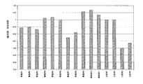
- FIG. 6 is a graph showing the results of the transmission performance test of the transmission V-belt in the example.
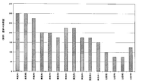
- FIG. 7 is a graph showing the results of a durability running test of the transmission V-belt in the example.
- the transmission V-belt of the present invention includes a core, an adhesive rubber layer in which at least a part of the core is embedded in the longitudinal direction of the belt, and a compression formed on one surface of the adhesive rubber layer. A rubber layer and a stretched rubber layer formed on the other surface of the adhesive rubber layer are provided.
- a V belt [wrapped V belt, low edge V belt, low edge cogged V belt (a low edge cogged V belt having a cog formed on the inner peripheral side of the low edge V belt, a low edge V belt).
- V-ribbed belts and the like V-ribbed belts and the like.
- a V belt or a V-ribbed belt having a transmission surface inclined in a V shape (or at a V angle) is preferable from the viewpoint of receiving a large lateral pressure from the pulley.
- a V-belt that is required to achieve a high level of fuel economy for example, a V-belt (for example, a low-edge cogged V-belt) used in a belt-type continuously variable transmission is particularly preferable.
- FIG. 2 is a schematic perspective view showing an example of a transmission V-belt (low edge cogged V-belt) according to the present invention
- FIG. 3 is a schematic cross-sectional view of the transmission V-belt of FIG. 2 cut in the belt longitudinal direction. is there.
- the transmission V-belt 1 has a plurality of cog mountain portions 1a formed at predetermined intervals along the longitudinal direction of the belt (A direction in the figure) on the inner peripheral surface of the belt body. is doing.
- the cross-sectional shape of the cog mountain portion 1a in the longitudinal direction is formed in a substantially semicircular shape (curved shape or wave shape), and the cross-sectional shape in a direction orthogonal to the longitudinal direction (width direction or B direction in the figure) is It is formed in a trapezoidal shape in which the belt width decreases from the belt outer peripheral side toward the inner peripheral side (cog mountain 1a side).
- each cog mountain portion 1a protrudes from the cog bottom portion 1b in the longitudinal direction (A direction) in the belt thickness direction so that the cross-sectional shape in the longitudinal direction (A direction) is a substantially semicircular shape. It is continuous along the direction (direction A).
- the transmission V-belt 1 has a laminated structure, and the reinforcing cloth 2, the stretch rubber layer 3, and the adhesive rubber layer 4 from the belt outer peripheral side toward the inner peripheral side (side where the cog mountain portion 1 a is formed).
- the compression rubber layer 5 and the reinforcing cloth (reinforcing cloth covering the cog mountain portion 1a and the cog bottom portion 1b) 6 are sequentially laminated. That is, the stretch rubber layer 3 and the compression rubber layer 5 are laminated via the adhesive rubber layer 4, and the reinforcing cloths 2 and 6 are laminated on the stretch rubber layer 3 and the compression rubber layer 5, respectively.
- a core body 4a is embedded in the adhesive rubber layer 4, and the cog portions (cog mountain portion 1a and cog bottom portion 1b) are formed in the compression rubber layer 5 by a cogging mold.
- the adhesive rubber layer (adhesive layer) is interposed between the stretched rubber layer and the compressed rubber layer to adhere the stretched rubber layer and the compressed rubber layer, and at least one of the cores is attached to the adhesive rubber layer (adhesive layer).
- the part is buried or in contact.
- This adhesive rubber layer is preferably formed of a vulcanized rubber composition containing a rubber component and a filler.
- the rubber component examples include known vulcanizable or crosslinkable rubber components and / or elastomers such as diene rubbers (for example, natural rubber, isoprene rubber, butadiene rubber, chloroprene rubber (CR), styrene butadiene rubber (SBR), Water of the diene rubbers such as vinylpyridine-styrene-butadiene copolymer rubber, acrylonitrile butadiene rubber (nitrile rubber); hydrogenated nitrile rubber (including mixed polymer of hydrogenated nitrile rubber and unsaturated carboxylic acid metal salt) Additives, etc.], olefin rubber [eg, ethylene- ⁇ -olefin rubber (ethylene- ⁇ -olefin elastomer), polyoctenylene rubber, ethylene-vinyl acetate copolymer rubber, chlorosulfonated polyethylene rubber, alkylated chloro Sulfonated polyethylene rubber, etc.]
- an ethylene- ⁇ -olefin elastomer ethylene-propylene copolymer (EPM), ethylene-propylene-diene terpolymer ( Ethylene- ⁇ -olefin rubbers such as EPDM) and chloroprene rubber are widely used, especially when used in high load environments such as transmission belts, mechanical strength, weather resistance, heat resistance, cold resistance, oil resistance, adhesion, etc.
- EPM ethylene-propylene copolymer
- EPDM ethylene-propylene-diene terpolymer
- chloroprene rubber is particularly preferable from the viewpoint of excellent wear resistance in addition to the above characteristics.
- the chloroprene rubber may be a sulfur-modified type or a non-sulfur-modified type.
- the proportion of the chloroprene rubber in the rubber component may be 50% by mass or more (particularly about 80 to 100% by mass), and 100% by mass (chloroprene rubber only) is particularly preferable.
- the filler examples include carbon black, silica, clay, calcium carbonate, talc, mica and the like.
- the filler often contains a reinforcing filler, and such reinforcing filler may be carbon black, reinforcing silica, or the like. Usually, the reinforcing property of silica is smaller than that of carbon black.
- These fillers can be used alone or in combination of two or more.
- the filler in order to dramatically improve fatigue fracture resistance and wear resistance, preferably contains at least a reinforcing filler (particularly carbon black), and carbon black and silica (for example, reinforcing silica) are included. It is also preferable to include.
- the average particle diameter of carbon black is, for example, about 5 to 200 nm, preferably about 10 to 150 nm, and more preferably about 15 to 100 nm. From the viewpoint of high reinforcing effect, the small particle diameter, for example, the average particle diameter is 5 to 38 nm.
- the carbon black may preferably be about 10 to 35 nm, more preferably about 15 to 30 nm. Examples of the carbon black having a small particle diameter include SAF, ISAF-HM, ISAF-LM, HAF-LS, HAF, and HAF-HS. These carbon blacks can be used alone or in combination.
- Carbon black can suppress deterioration in processability even when blended in large amounts, and can improve the mechanical properties (elastic modulus) of the adhesive rubber layer. Furthermore, carbon black can reduce the friction coefficient of the adhesive rubber layer and improve the wear resistance of the adhesive rubber layer. In addition, when the content of carbon black increases, the bending fatigue resistance may decrease.
- the proportion of carbon black can be selected from the range of about 20 to 100 parts by mass (for example, 20 to 80 parts by mass, preferably 20 to 60 parts by mass) with respect to 100 parts by mass of the rubber component. It may be about (for example, 25 to 50 parts by mass), preferably about 25 to 45 parts by mass (for example, 30 to 40 parts by mass). If the proportion of carbon black is too small, the elastic modulus may be insufficient and the fatigue fracture resistance and wear resistance may be reduced. If it is too large, the elastic modulus will be too high and the bending fatigue resistance may be reduced. There is.
- the filler preferably further contains silica (such as reinforcing silica).
- silica such as reinforcing silica
- Silica is a fine bulky white powder formed of silicic acid (anhydrous or hydrous silicic acid) and / or silicate, and since there are a plurality of silanol groups on its surface, a rubber component Can be chemically bonded.
- Silica includes dry silica, wet silica, surface-treated silica, and the like. Silica can also be classified into, for example, dry process white carbon, wet process white carbon, colloidal silica, precipitated silica, gel process silica (silica gel), etc., according to the classification in the production process. These silicas can be used alone or in combination of two or more. Of these, wet white carbon containing hydrous silicic acid as a main component is preferable because it has many surface silanol groups and strong chemical bonding with rubber.
- the average particle diameter of silica is, for example, about 1 to 1000 nm, preferably 3 to 300 nm, more preferably 5 to 100 nm (particularly 10 to 50 nm). If the particle size of the silica is too large, the mechanical properties of the adhesive rubber layer may be reduced, and if it is too small, it may be difficult to uniformly disperse.
- Silica may be non-porous or porous, but the nitrogen adsorption specific surface area by the BET method is, for example, 50 to 400 m 2 / g, preferably 70 to 350 m 2 / g, more preferably 100. It may be about ⁇ 300 m 2 / g (especially 150 to 250 m 2 / g). If the specific surface area is too large, it may be difficult to uniformly disperse, and if the specific surface area is too small, the mechanical properties of the adhesive rubber layer may be reduced.
- the ratio of silica is, for example, 5 to 35 parts by mass (eg 10 to 35 parts by mass), preferably 10 to 30 parts by mass (eg 15 to 25 parts by mass), more preferably 100 parts by mass of the rubber component. May be about 12 to 25 parts by mass (for example, 15 to 20 parts by mass). If the proportion of silica is too small, the effect of improving the adhesiveness may not be exhibited.
- the mass ratio of carbon black to silica (the former / the latter) can be selected from the range of about 40/60 to 100/0 (for example, 45/55 to 90/10), for example, 40/60 to 85/15 ( For example, it may be about 50/50 to 80/20), preferably about 60/40 to 75/25 (for example, 60/40 to 70/30).
- the proportion of silica is usually less than that of carbon black.
- 50 mass% or more may be sufficient as the ratio of carbon black with respect to the whole filler. If the proportion of carbon black is too small, the mechanical properties of the adhesive rubber layer may be reduced.
- the proportion (total proportion) of the filler can be selected from the range of about 30 to 100 parts by mass with respect to 100 parts by mass of the rubber component, for example, 30 to 75 parts by mass, preferably 35 to 70 parts by mass, and more preferably 40 parts. It may be about ⁇ 65 parts by mass (for example, 45 to 60 parts by mass). If the proportion of the filler is too small, the wear resistance may decrease due to a decrease in the elastic modulus. Conversely, if it is too large, the elastic modulus will be too high and heat will be generated, and the stretched rubber layer and the compressed rubber layer will crack. May occur early.
- the rubber composition for forming the adhesive rubber layer includes a vulcanizing agent or a crosslinking agent, a co-crosslinking agent, a vulcanization aid, a vulcanization accelerator, a vulcanization retarder, a metal oxide (for example, as necessary) Zinc oxide, magnesium oxide, lead oxide, calcium oxide, barium oxide, iron oxide, copper oxide, titanium oxide, aluminum oxide, etc.), softener (oils such as paraffin oil and naphthenic oil), processing agent or processing Auxiliaries (fatty acids such as stearic acid, fatty acid metal salts such as metal stearate, fatty acid amides such as stearic acid amide, wax, paraffin, etc.), adhesion improver [resorcin-formaldehyde cocondensate (RF condensate), Amino resins (condensates of nitrogen-containing cyclic compounds and formaldehyde such as hexamethylol melamine, hexaal
- the metal oxide may act as a crosslinking agent.
- the resorcin-formaldehyde cocondensate and amino resin may be an initial condensate (prepolymer) of a nitrogen-containing cyclic compound such as resorcin and / or melamine and formaldehyde.
- the vulcanizing agent or crosslinking agent conventional components can be used depending on the type of rubber component.
- the metal oxide vulcanizing agent magnesium oxide, zinc oxide, lead oxide, etc.
- organic peroxide diacyl
- sulfur vulcanizing agents sulfur vulcanizing agents and the like.
- the sulfur-based vulcanizing agent include powdered sulfur, precipitated sulfur, colloidal sulfur, insoluble sulfur, highly dispersible sulfur, sulfur chloride (sulfur monochloride, sulfur dichloride, etc.), and the like.
- These crosslinking agents or vulcanizing agents may be used alone or in combination of two or more.
- a metal oxide magnesium oxide, zinc oxide, etc.
- the metal oxide may be used in combination with other vulcanizing agents (such as sulfur-based vulcanizing agents), and the metal oxide and / or sulfur-based vulcanizing agent may be used alone or in combination with a vulcanization accelerator. May be used.
- the proportion of the vulcanizing agent can be selected from a range of about 1 to 20 parts by mass with respect to 100 parts by mass of the rubber component depending on the types of the vulcanizing agent and the rubber component.
- the ratio of the metal oxide as the vulcanizing agent is 1 to 20 parts by weight, preferably 3 to 17 parts by weight, more preferably 5 to 15 parts by weight (for example, 7 to 13 parts) with respect to 100 parts by weight of the rubber component.
- the ratio of the organic peroxide is 1 to 8 parts by weight, preferably 1.5 to 5 parts by weight, more preferably 2 to 4.5 parts by weight based on 100 parts by weight of the rubber component. It can be selected from a range of about part by mass.
- co-crosslinking agent crosslinking aid or co-vulcanizing agent co-agent
- crosslinking aids such as polyfunctional (iso) cyanurates [for example, triallyl isocyanurate (TAIC), triallyl cyanurate ( TAC), etc.], polydienes (eg, 1,2-polybutadiene, etc.), metal salts of unsaturated carboxylic acids [eg, (meth) acrylic acid polyvalent metals such as zinc (meth) acrylate, magnesium (meth) acrylate, etc.
- oximes for example, quinonedioxime, etc.
- guanidines for example, diphenylguanidine, etc.
- polyfunctional (meth) acrylates for example, ethylene glycol di (meth) acrylate, butanediol di (meth) acrylate, etc.
- Alkane polyol poly (meth) acrylates such as pentaerythritol tetra (meth) acrylate]
- bismaleimides aliphatic bismaleimides such as N, N′-1,2-ethylenedimaleimide, N, N′-hexamethylene
- Alkylene bismaleimides such as bismaleimide, 1,6′-bismaleimide- (2,2,4-trimethyl) cyclohexane; arene bismaleimides or aromatic bismaleimides such as N, N′-m-
- crosslinking aids can be used alone or in combination of two or more.
- polyfunctional (iso) cyanurates, polyfunctional (meth) acrylates, bismaleimides (arene bismaleimides such as N, N′-m-phenylene dimaleimide or aromatic bismaleimides) are preferred, Bismaleimides are often used.
- a crosslinking aid for example, bismaleimides
- the degree of crosslinking can be increased and adhesive wear and the like can be prevented.
- the ratio of the co-crosslinking agent (cross-linking aid) such as bismaleimides can be selected from the range of about 0.1 to 10 parts by mass with respect to 100 parts by mass of the rubber component in terms of solid content. Even if it is about 6 parts by mass, preferably about 0.5 to 5 parts by mass (eg 1 to 5 parts by mass), more preferably about 1.5 to 3 parts by mass (eg 1.5 to 2.5 parts by mass) Usually, it may be about 1 to 3 parts by mass (for example, 1 to 2.5 parts by mass).
- vulcanization accelerator examples include thiuram accelerators [for example, tetramethylthiuram monosulfide (TMTM), tetramethylthiuram disulfide (TMTD), tetraethylthiuram disulfide (TETD), tetrabutylthiuram disulfide (TBTD).
- TMTM tetramethylthiuram monosulfide
- TMTD tetramethylthiuram disulfide
- TETD tetraethylthiuram disulfide
- TBTD tetrabutylthiuram disulfide
- thiazole accelerators eg, 2-mercaptobenzothiazol, 2 -Zinc salts of mercaptobenzothiazol, 2-mercaptothiazoline, dibenzothiazyl disulfide, 2- (4'-morpholinodithio) benzothiazole, etc.
- sulfenamide accelerators for example, N-cyclohexyl-2 -Benzothiazylsulfe Amides (CBS), N, N′-dicyclohexyl-2-benzothiazylsulfenamide, etc.]
- guanidines diphenylguanidine, di-tolylguanidine, etc.
- urea-based or thiourea-based accelerators for example, ethylenethiourea, etc.
- the ratio of the vulcanization accelerator is, for example, 0.1 to 15 parts by mass (for example, 0.3 to 10 parts by mass), preferably 0.5 to 5 parts by mass with respect to 100 parts by mass of the rubber component in terms of solid content. It may be about (for example, 0.5 to 3 parts by mass) or about 0.3 to 2.5 parts by mass (for example, 0.5 to 1.5 parts by mass).
- the ratio of the softening agent is, for example, 1 to 30 parts by mass (eg 3 to 20 parts by mass), preferably 3 to 10 parts by mass (100 parts by mass with respect to the total amount of rubber components). For example, it may be about 3 to 8 parts by mass.
- the ratio of the processing agent or processing aid eg, stearic acid
- it may be about 0.5 to 3 parts by mass), more preferably about 1 to 3 parts by mass (for example, 1.5 to 2.5 parts by mass).
- the ratio of the adhesion improver is 0.1 to 20 parts by mass (for example, 0.2 to 10 parts by mass), preferably 100 parts by mass of the rubber component. May be about 0.3 to 5 parts by mass (eg 0.5 to 2.5 parts by mass), more preferably about 0.5 to 3 parts by mass (eg 0.5 to 1.5 parts by mass). Good.
- the proportion of the antioxidant is, for example, 0.5 to 15 parts by weight, preferably 1 to 10 parts by weight, more preferably 2.5 to 7.5 parts by weight (particularly 3 parts by weight) with respect to 100 parts by weight of the total amount of rubber components. About 7 parts by mass).
- core wires twisted cords
- the cores are arranged to extend in the longitudinal direction of the belt, and are usually arranged to extend in parallel at a predetermined pitch in parallel with the longitudinal direction of the belt.
- the core body or the core wire only needs to be partially embedded in the adhesive rubber layer, and from the point that durability can be improved, the core wire is embedded in the adhesive rubber layer (the entire core wire is the adhesive rubber layer In a completely embedded form).
- fibers constituting the core wire examples include polyolefin fibers (polyethylene fibers, polypropylene fibers, etc.), polyamide fibers (polyamide 6 fibers, polyamide 66 fibers, polyamide 46 fibers, aramid fibers, etc.), polyester fibers (polyalkylene arylate series).
- Fiber [poly C 2-4 alkylene C 6-14 arylate fiber such as polyethylene terephthalate (PET) fiber, polyethylene naphthalate (PEN) fiber, etc.], vinylon fiber, polyvinyl alcohol fiber, polyparaphenylene benzobisoxazole ( Synthetic fibers such as PBO) fibers; natural fibers such as cotton, hemp and wool; inorganic fibers such as carbon fibers are widely used. These fibers can be used alone or in combination of two or more.
- PET polyethylene terephthalate
- PEN polyethylene naphthalate
- Synthetic fibers such as PBO
- natural fibers such as cotton, hemp and wool
- inorganic fibers such as carbon fibers are widely used.
- polyester fibers polyalkylene arylate fibers mainly composed of C 2-4 alkylene arylates such as ethylene terephthalate and ethylene-2,6-naphthalate, polyamide fibers (aramids) Synthetic fibers such as fibers) and inorganic fibers such as carbon fibers are widely used, and polyester fibers (particularly polyethylene terephthalate fibers and polyethylene naphthalate fibers) and polyamide fibers (particularly aramid fibers) are preferred.
- the fiber may be a multifilament yarn.
- the fineness of the multifilament yarn may be, for example, about 2000 to 10000 denier (particularly 4000 to 8000 denier).
- the multifilament yarn may contain, for example, about 100 to 5,000 monofilament yarns, preferably about 500 to 4,000, more preferably about 1,000 to 3,000 monofilament yarns. May be.
- the core wire usually a twisted cord using multifilament yarn (for example, various twists, single twists, rung twists, etc.) can be used.
- the average wire diameter (fiber diameter of the twisted cord) of the core wire may be, for example, 0.5 to 3 mm, preferably 0.6 to 2 mm, more preferably about 0.7 to 1.5 mm. Good.
- the core wire may be surface-treated in order to improve the adhesion with the adhesive rubber layer.
- the surface treatment agent for example, an RFL liquid containing resorcin (R), formaldehyde (F) and rubber or latex (L) (for example, resorcin (R) and formaldehyde (F) are condensates (RF condensates).
- the rubber component for example, RFL liquid containing vinylpyridine-styrene-butadiene copolymer rubber), epoxy compound, polyisocyanate compound, silane coupling agent, the rubber component and silica (for example, surface silanol group) And a vulcanized rubber composition containing a wet process white carbon mainly composed of hydrous silicic acid, which is advantageous for enhancing the chemical bond strength with rubber.
- surface treatment agents may be used alone or in combination of two or more thereof, and may be sequentially treated with the same or different surface treatment agent a plurality of times.
- the core wire is preferably bonded with at least an RFL solution.
- the hardness H1 of the adhesive rubber layer is high on the compressed rubber layer side and low on the stretched rubber layer side.
- the rubber hardness H1 of the adhesive rubber layer may be reduced stepwise (or layered) or continuously as it goes from the compressed rubber layer side to the stretched rubber layer side.
- At least part of which is embedded in the adhesive rubber layer forms the core (core wire), rubber hardness H1 2 than core decompression rubber layer side (top side or outer circumferential side), usually, the compression rubber layer side ( It is formed stepwise or continuously smaller (H1 2 ⁇ H1 3 ) than the rubber hardness H1 3 on the lower surface side or the inner peripheral side.
- the hardness H1 of the adhesive rubber layer can be expressed as a rubber hardness having a predetermined distribution width (range), and a weighted average based on the average rubber hardness (for example, the hardness of a plurality of rubber layers and the thickness of each layer). (Rubber hardness).
- Such an adhesive rubber layer may include at least a plurality of adhesive rubber layers having different rubber hardnesses, for example, a first adhesive rubber layer in contact with the stretch rubber layer, and a second adhesive rubber layer in contact with the compression rubber layer.
- the core is interposed between the first adhesive rubber layer and the second adhesive rubber layer in direct contact with these adhesive rubber layers or through one or more intermediate rubber layers. Also good.
- the adhesive rubber layer can be formed by changing a predetermined component that affects the hardness of the rubber layer and its quantitative ratio.
- the adhesive rubber layer may be formed by increasing the content of softening components such as a softener and a plasticizer on the stretched rubber layer side rather than the compressed rubber layer side.
- the adhesive rubber layer may be formed by reducing the amount on the stretched rubber layer side rather than the compressed rubber layer side.
- the filler may contain at least a reinforcing filler (such as carbon black), or may include a reinforcing filler (such as carbon black) and an inorganic filler (such as silica such as reinforcing silica).
- the reinforcing filler may contain carbon black and reinforcing silica.
- the rubber hardness H1 of the adhesive rubber layer is often adjusted by the content of at least one component selected from fillers containing at least carbon black and bismaleimides. More specifically, at least one component selected from carbon black, silica (such as reinforcing silica) and co-crosslinking agent (such as bismaleimides) (particularly at least carbon black and co-crosslinking agent (such as bismaleimides)). ) Is increased in the second adhesive rubber layer in contact with the compression rubber layer rather than in the first adhesive rubber layer in contact with the extension rubber layer, so that the rubber hardness on the compression rubber layer side is higher than that on the extension rubber layer side. Can be bigger.
- the filler is, for example, 30 to 75 parts by mass, preferably 35 to 70 parts by mass, and more preferably 100 parts by mass of the rubber component (chloroprene rubber and the like). It may be contained in a proportion of about 40 to 65 parts by mass (for example, 45 to 60 parts by mass).
- carbon black in the filler is, for example, 20 to 50 parts by mass (for example, 25 to 50 parts by mass), preferably 25 to 45 parts by mass (for example, relative to 100 parts by mass of the rubber component (chloroprene rubber or the like).
- silica is, for example, 10 to 30 parts by mass, preferably 12 to 25 parts by mass (for example, 15 to 20 parts by mass). It may be included in a proportion.
- the content of the vulcanizing agent is, for example, 1-20 parts by mass (eg, 3-17 parts by mass) with respect to 100 parts by mass of the rubber component (chloroprene rubber, etc.) Preferably, it may be about 5 to 15 parts by mass (for example, 7 to 13 parts by mass).
- the content of the co-crosslinking agent bismaleimides and the like is, for example, 0.3 to 7 parts by mass (for example, 0 0.5-5 parts by mass), preferably about 0.7-4 parts by mass (eg, 1-3 parts by mass).
- the first adhesive rubber layer in contact with the stretch rubber layer has a filler of, for example, 25 to 65 parts by mass (for example, 30 to 62 parts) with respect to 100 parts by mass of the rubber component (chloroprene rubber or the like). Part by mass), preferably 40 to 60 parts by mass (for example, 45 to 55 parts by mass).
- the content of carbon black is, for example, 20 to 50 parts by mass (eg 25 to 45 parts by mass), preferably 30 to 40 parts by mass (eg 30 to 30 parts by mass) with respect to 100 parts by mass of the rubber component (chloroprene rubber etc.).
- the content of silica is, for example, 5 to 30 parts by mass (eg 10 to 25 parts by mass), preferably 12 to 23 parts by mass (eg 15 to 15 parts by mass). 20 parts by mass).
- the content of the co-crosslinking agent (bismaleimides, etc.) with respect to 100 parts by mass of the rubber component (chloroprene rubber, etc.) is, for example, 0.3-5 parts by mass (eg 0.5-3 parts by mass), preferably May be about 0.7 to 2.5 parts by mass (eg, 1 to 2 parts by mass).
- the content of the vulcanizing agent may be the same as the content in the adhesive rubber layer.
- the second adhesive rubber layer in contact with the compression rubber layer is, for example, 45 to 70 parts by mass, preferably 50 to 65 parts by mass (for example, 50 to 65 parts by mass) with respect to 100 parts by mass of the rubber component (chloroprene rubber or the like).
- the carbon black may be contained in a proportion of about 55 to 65 parts by mass, for example, 30 to 60 parts by mass (eg 30 to 50 parts by mass), preferably 35 to 50 parts by mass (eg 35 to 45 parts by mass).
- silica (reinforcing silica, etc.) may be contained, for example, at a ratio of about 10 to 30 parts by mass (for example, 15 to 25 parts by mass).
- the content of the co-crosslinking agent is, for example, 1 to 7 parts by mass (for example, 1.5 to 5 parts by mass), preferably 1 with respect to 100 parts by mass of the rubber component (chloroprene rubber or the like). It may be about 5 to 4.5 parts by mass (for example, 2 to 4 parts by mass).
- the content of the vulcanizing agent may be the same as the content in the adhesive rubber layer.
- the rubber hardness H1 of the adhesive rubber layer may be, for example, in the range of 70 to 85 ° (eg, 72 to 84 °), preferably 73 to 83 ° (eg, 74 to 82 °). It may be in the range of about 85 ° (for example, 75 to 84 °), preferably about 78 to 83 ° (for example, 80 to 82 °).
- it may be about 74 to 82 ° (for example, 74 to 80 °), or may be about 76 to 83 ° (for example, 80 to 82 °).
- the rubber hardness of the compression rubber layer (toward the bottom surface or the inner peripheral side) (for example, rubber hardness of the second adhesive rubber layer) H1 3, rather than the rubber hardness of the extensible rubber layer side (top side or outer circumferential side) It may be larger, for example, 77 to 85 ° (eg, 78 to 85 °), preferably 78 to 84 ° (eg, 79 to 83 °), and more preferably about 80 to 84 ° (eg, 81 to 83 °). It may be.
- Stretching rubber layer side difference of the rubber hardness H1 3 between the rubber hardness H1 2 and the compression rubber layer side (inner peripheral side) of the (outer peripheral side) ( ⁇ (H1 3 -H1 2)) is, for example, 1 ⁇ 12 ° ( For example, it may be 2 to 12 °), preferably 2 to 10 ° (eg 3 to 9 °), more preferably about 2 to 8 °.
- the hardness (or average rubber hardness) H1 of the adhesive rubber layer is usually lower than the rubber hardness H2 of the stretched rubber layer and the rubber hardness H3 of the compressed rubber layer, and the rubber hardness H2 of the stretched rubber layer is compressed. It is formed lower than the rubber hardness H3 of the rubber layer (H1 ⁇ H2 ⁇ H3).
- Relates rubber hardness H1 of the adhesive rubber layer, (a rubber hardness of the extensible rubber layer side (outer peripheral side)) H1 2 rubber hardness of the first adhesive rubber layer in contact with the extensible rubber layer is equivalent to the rubber hardness H2 of stretching rubber layer It may be present (H1 2 ⁇ H2) and is usually lower than the rubber hardness H2 (H1 2 ⁇ H2).
- rubber hardness of the compression rubber layer side (inner peripheral side)) rubber hardness of the second adhesive rubber layer in contact with the compressed rubber layer H1 3 may be the same as the hardness H3 of the compression rubber layer (H1 3 ⁇ H3) Usually, it is often lower than the rubber hardness H3 (H1 3 ⁇ H3).
- the average thickness of the adhesive rubber layer can be selected according to the type of transmission V-belt, and is, for example, 0.2 to 3 mm (for example, 0.3 to 2.5 mm), preferably 0.4 to 2.2 mm (for example, 0.6 to 2 mm), more preferably about 0.8 to 1.5 mm (for example, 0.8 to 1.4 mm).
- the average thickness of the adhesive rubber layer is, for example, 0.1 to 2.5 mm (for example, 0.2 to 2.0 mm), preferably 0.3 to 1.5 mm (for example, 0.4 to 1.0 mm).
- the vulcanized rubber composition for forming the stretched rubber layer (back rubber layer or back layer) and the compressed rubber layer (inner rubber layer or inner layer) is the same component as the vulcanized rubber composition of the adhesive rubber layer,
- rubber components chloroprene rubber, EPDM, etc.
- vulcanizing agents or crosslinking agents metal oxides such as magnesium oxide and zinc oxide, sulfur vulcanizing agents such as sulfur
- co-crosslinking agents or crosslinking aids N , N'-m-phenylene dimaleimide and other bismaleimides
- vulcanization accelerators TMTD, DPTT, CBS, etc.
- fillers carbon black, silica, clay, calcium carbonate, talc, mica, etc.
- softeners Olenic oils
- processing agents or processing aids stearic acid, metal stearate, wax, paraffin, etc.
- anti-aging agents adhesion improvers, colorants
- It may contain
- the vulcanized rubber composition for forming the stretched rubber layer and the compressed rubber layer may contain short fibers.
- the same fibers as the fibers constituting the core can be used.
- the short fiber formed with the said fiber can be used individually or in combination of 2 or more types.
- synthetic fibers and natural fibers in particular polyester fibers mainly composed of C 2-4 alkylene C 6-12 arylates such as ethylene terephthalate and ethylene-2,6-naphthalate (polyalkylene arylates) Fibers), synthetic fibers such as polyamide fibers (such as aramid fibers), inorganic fibers such as carbon fibers, etc., among which rigid, high-strength and modulus fibers such as polyester fibers (particularly polyethylene terephthalate fibers, polyethylene fibers).
- Aramid short fibers also have high wear resistance. Therefore, it is preferable that the short fiber includes at least an aramid fiber.
- Aramid fibers are commercially available, for example, under the trade names “Conex”, “Nomex”, “Kevlar”, “Technola”, “Twaron”, and the like.
- the average fiber diameter of the short fibers may be about 2 ⁇ m or more, for example, 2 to 100 ⁇ m, preferably 3 to 50 ⁇ m (for example 5 to 50 ⁇ m), more preferably 7 to 40 ⁇ m (particularly 10 to 30 ⁇ m).
- the average length of the short fibers is, for example, 1 to 20 mm (for example, 1.2 to 20 mm), preferably 1.3 to 15 mm (for example, 1.5 to 10 mm), and more preferably 2 to 5 mm (for example, 2.5 to 4 mm). ) Degree.
- the short fibers may be subjected to adhesion treatment (or surface treatment) by a conventional method. Further, the short fiber may be protruded from the surface by polishing the surface (friction transmission surface) of the belt.
- the average protruding height of the short fibers may be about 50 ⁇ m or more (for example, 50 to 200 ⁇ m).
- the short fibers may be oriented in the belt width direction and embedded or contained in the stretched rubber layer and the compressed rubber layer.
- the proportion of the short fibers can be selected from the range of about 5 to 50 parts by mass with respect to 100 parts by mass of the rubber component, and is usually 5 to 40 parts by mass (for example, 10 to 35 parts by mass), preferably 15 to 35 parts by mass. Part (for example, 15 to 30 parts by mass), more preferably about 20 to 30 parts by mass (for example, 20 to 25 parts by mass).
- rubber component rubber of the same type or the same type (diene rubber, chloroprene rubber, etc.) as the rubber component of the rubber composition of the adhesive rubber layer is often used.
- each component may be selected from the same range as the rubber composition of the adhesive rubber layer.
- the filler ratio can be selected from a range of about 10 to 100 parts by mass (for example, 15 to 80 parts by mass) with respect to 100 parts by mass of the rubber component (chloroprene rubber or the like). Usually, it may be about 20 to 70 parts by mass (for example, 25 to 60 parts by mass), preferably about 30 to 55 parts by mass (for example, 30 to 50 parts by mass).
- the filler at least carbon black is often used, and silica may be used in combination, but silica is not always necessary.
- the ratio of the vulcanizing agent is 1 to 20 parts by mass (for example, 3 to 17 parts by mass, preferably 5 to 15 parts by mass, more preferably 7 parts by mass with respect to 100 parts by mass of the rubber component. (About 13 mass parts).
- the ratio of the co-crosslinking agent or crosslinking aid can be selected from the range of about 1.5 to 7 parts by mass with respect to 100 parts by mass of the rubber component, and usually 2 to 5 parts by mass (for example, 2 0.5 to 4 parts by mass), preferably about 2.5 to 3.5 parts by mass.
- the rubber hardness H2 of the stretch rubber layer is formed lower than the rubber hardness H3 of the compression rubber layer (H2 ⁇ H3).
- the hardness of these rubber layers can be adjusted, for example, by changing a predetermined component that affects the hardness of the rubber layer and its quantitative ratio in the rubber composition of the stretched rubber layer and the compressed rubber layer.
- the content of softening components such as softeners and plasticizers may be adjusted by increasing the stretched rubber layer rather than the compressed rubber layer.
- the content of at least one component selected from the above may be adjusted by reducing the stretched rubber layer rather than the compressed rubber layer.
- At least one component selected from reinforcing fillers such as carbon black
- co-crosslinking agents such as bismaleimides
- short fibers in particular, at least one component selected from carbon black and short fibers
- the rubber composition of the stretched rubber layer contains 15 to 50 parts by mass (for example, 20 to 40 parts by mass), preferably 25 to 45 parts by mass of filler (carbon black and the like) with respect to 100 parts by mass of the rubber component (chloroprene and the like). Part (for example, 30 to 40 parts by mass).
- the short fiber content is 5 to 35 parts by mass (eg 10 to 35 parts by mass), preferably 15 to 30 parts by mass (eg 15 to 25 parts by mass) with respect to 100 parts by mass of the rubber component (chloroprene rubber or the like). Part) degree.
- the rubber composition of the compression rubber layer contains 20 to 70 parts by mass (for example, 25 to 60 parts by mass), preferably 35 to 55 parts by weight of filler (carbon black or the like) with respect to 100 parts by mass of the rubber component (chloroprene rubber or the like). It may be contained at a ratio of about part by mass (for example, 40 to 50 parts by mass).
- the content of the short fiber is 10 to 40 parts by mass (for example, 15 to 35 parts by mass), preferably 20 to 35 parts by mass (for example, 20 to 30 parts by mass) with respect to 100 parts by mass of the rubber component (chloroprene rubber or the like). Part) degree.
- the contents of the vulcanizing agent (metal oxide vulcanizing agent, etc.) and the co-crosslinking agent or crosslinking auxiliary agent (bismaleimides, etc.) were the same in the rubber composition of the stretch rubber layer and the compression rubber layer, respectively.
- the content of the compressed rubber layer may be larger than that of the stretched rubber layer.
- the rubber hardness H2 of the stretched rubber layer is, for example, 80 to 92 ° (eg, 81 to 92 °), preferably 82 to 92 ° (eg, 82 to 90 °), and more preferably 83 to 90 ° (eg, 83). About 89 °) or about 80-86 ° (for example, 82-85 °).
- the rubber hardness H3 of the compressed rubber layer is, for example, about 86 to 98 ° (eg, 87 to 97 °), preferably 88 to 96 ° (eg, 89 to 95 °), and more preferably about 88 to 95 °. Alternatively, it may be about 86 to 95 ° (for example, 86 to 93 °), preferably about 87 to 92 ° (for example, 88 to 91 °).
- the difference in rubber hardness ( ⁇ (H3-H2)) between the stretched rubber layer and the compressed rubber layer is, for example, 2 to 12 ° (eg, 3 to 11 °), preferably 3 to 10 ° (eg, 4 to 9). °), more preferably about 4 to 8 ° (for example, 5 to 7 °).
- the average thickness of the stretched rubber layer can be selected according to the type of transmission V-belt, and is, for example, 0.6 to 10 mm (for example, 0.8 to 7 mm), preferably 1 to 6.5 mm (for example, 1.2). To 6 mm), more preferably about 1.4 to 5.2 mm (for example, 1.6 to 5 mm), and the average thickness of the compressed rubber layer is, for example, 2 to 25 mm depending on the type of belt. (For example, 3 to 20 mm), preferably 3 to 18 mm (for example, 3 to 16 mm), more preferably about 4 to 15 mm (for example, 5 to 12 mm).
- the average thickness of the stretched rubber layer is, for example, 0.4 to 5 mm (for example, 0.5 to 4 mm), preferably 0.6 to 3 mm (for example, 0.7 to
- the average thickness of the compressed rubber layer is, for example, about 1 to 10 mm (for example, 1.5 to 9 mm), preferably about 2 to 8 mm (for example, 3 to 7 mm). Also good.
- the cog formed in the cog mountain part and the cog valley part is formed in the inner peripheral surface side of the compression rubber layer of this aspect.
- the shape of the cogs is not particularly limited, and may be a curved wave shape, for example.
- the reinforcing fabric layer is not always necessary. Also, when a reinforcing cloth layer is provided, the reinforcing cloth forming the reinforcing cloth layer is made of both an extended rubber layer and a compressed rubber layer (a cog when the cog is formed integrally with the compressed rubber layer) (extended rubber layer).
- the upper surface and the lower surface of the compressed rubber layer) are not limited to the form of lamination.
- a reinforcing fabric may be laminated on the surface of one of the stretched rubber layer and the compressed rubber layer (including cogs), and a reinforcing layer is provided on the compressed rubber layer and / or the stretched rubber layer.
- An embedded form for example, a form described in Japanese Patent Application Laid-Open No.
- the reinforcing cloth is laminated on the surface of at least one of the stretched rubber layer and the compressed rubber layer (the upper surface of the stretched rubber layer and / or the lower surface of the compressed rubber layer), for example, the upper surface of the stretched rubber layer and the compressed rubber.
- the layers are stacked on both sides.
- the reinforcing cloth can be formed of, for example, a cloth material (preferably a woven cloth) such as a woven cloth, a wide angle sail cloth, a knitted cloth, and a non-woven cloth.
- a cloth material preferably a woven cloth
- an adhesive treatment for example, treatment with an RFL liquid (immersion treatment, etc.)
- a friction treatment in which adhesive rubber is rubbed into the cloth material, or the adhesive rubber and the cloth material are laminated (coated) and then laminated or embedded in the compressed rubber layer and / or the stretched rubber layer in the above-described form. May be.
- the average thickness of the transmission V-belt of the present invention is, for example, 12 mm or less (for example, 3 to 12 mm), preferably 10 mm or less (for example, 5 to 10 mm), more preferably 9 mm or less (for example, 6 to 9 mm). It may be about 6.5 to 8.5 mm.
- the thickness of the transmission V-belt means the thickness of the entire belt.
- the method for producing the transmission V-belt of the present invention is not particularly limited, and a conventional method can be used in accordance with the type of the belt with respect to the laminating step of each layer (the method for producing the belt sleeve).
- a typical manufacturing method of the cogd V belt will be described.
- a laminated body of a reinforcing cloth (under cloth) and a compressed rubber layer sheet (unvulcanized rubber sheet) is used, and the reinforcing cloth is used as a tooth part.
- a pad that is not vulcanized and is in a semi-vulcanized state is prepared. You may cut
- a cylindrical mold is covered with an inner mother die in which teeth and grooves are alternately arranged, engaged with the teeth and grooves, a cog pad is wound, and joints are made at both ends (particularly at the top of the cog crest).
- the second adhesive rubber layer sheet lower adhesive rubber: unvulcanized rubber sheet
- the core wire twisted cord
- a first adhesive rubber layer sheet upper adhesive rubber: unvulcanized rubber sheet
- a stretch rubber layer sheet unvulcanized rubber sheet
- a reinforcing cloth upper cloth
- the jacket is put on the molded body, the mold is placed in a vulcanizing can, and vulcanized at a temperature of about 120 to 200 ° C. (especially 150 to 180 ° C.) to prepare a belt sleeve. Then, it cuts into V shape using a cutter etc. *
- the adhesive rubber layer can be formed of a plurality of adhesive rubber layer sheets, and the core wire (twisted cord) that forms the core is formed of a plurality of adhesive rubber layer sheets according to the position embedded in the adhesive rubber layer. Spinning may be performed in association with the stacking order. Further, as described above, it is not always necessary to form the cogs, and the reinforcing cloth (lower cloth and upper cloth) is not necessarily required.
- Chloroprene rubber “PM-40” manufactured by Denki Kagaku Kogyo Co., Ltd. Carbon black: “Seast 3” manufactured by Tokai Carbon Co., Ltd. Silica: “Nipsil VN3” manufactured by Tosoh Silica Corporation Naphthenic oil: “NS-900” manufactured by Idemitsu Kosan Co., Ltd. Magnesium oxide resorcin / formalin copolymer (resorcinol resin): resorcinol less than 20%, formalin less than 0.1% anti-aging agent: Seiko Chemical Co., Ltd.
- Nonflex OD3 Zinc oxide Vulcanization accelerator TMTD: Tetramethylthiuram disulfide N, N'-m-phenylenedimaleimide: "Barunok PM” manufactured by Ouchi Shinsei Chemical Co., Ltd.
- Stearic acid hexamethoxymethylolmelamine Aramid short fiber “Conex short fiber” manufactured by Teijin Techno Products Limited, average fiber length 3 mm, average fiber diameter 14 ⁇ m, RFL solution (2.6 parts of resorcin, 1.4 parts of 37% formalin) Short fiber having a solid content of 6% by mass bonded with vinyl pyridine-styrene-butadiene copolymer latex (Nippon Zeon Co., Ltd.
- Polyester short fiber Teijin 3mm average short fiber length manufactured by Techno Products
- Sulfur core wire Total denier 6,000 twisted cord obtained by twisting 1,000 denier PET fibers in a 2 ⁇ 3 twist configuration with an upper twist factor of 3.0 and a lower twist factor of 3.0.
- the transmission performance test was performed using a two-axis running test machine including a driving (DR) pulley 22 having a diameter of ⁇ 95 mm and a driven (DN) pulley 23 having a diameter of ⁇ 95 mm.
- DR driving
- DN driven
- a low-edge cogged V-belt 21 is hung on each pulley 22 and 23, the rotational speed of the drive pulley 22 is 4,500 rpm, a 0.2 kN axial load is applied to the driven pulley 23, and the ambient temperature is room temperature (about 20 ° C.).
- the low-edge cogged V-belt 21 was caused to travel by applying a load of 2.5 Nm with a load device (power generation device).
- the transmission efficiency is an index for the belt to transmit the rotational torque from the drive pulley to the driven pulley, and the higher the transmission efficiency, the smaller the belt transmission loss and the better the fuel efficiency.
- the rotational torque T 1 of the driving pulley can be expressed by ⁇ 1 ⁇ Te ⁇ r 1 .
- Te is an effective tension obtained by subtracting the loose side tension (tension on the side where the belt faces the driven pulley) from the tension side tension (tension on the side where the belt faces the driving pulley).
- the rotational torque T 2 of the driven pulley is represented by ⁇ 2 ⁇ Te ⁇ r 2 .
- the transmission efficiency T 2 / T 1 is calculated by dividing the rotational torque T 2 of the driven pulley by the rotational torque T 1 of the drive pulley, and can be expressed by the following equation.
- the value of transmission efficiency is 1 if there is no transmission loss, and the value decreases if there is a transmission loss. That is, the closer to 1, the smaller the belt transmission loss and the better the fuel economy.
- the endurance running test was performed using a two-axis running test machine including a driving (DR) pulley 27 having a diameter of ⁇ 50 mm and a driven (DN) pulley 28 having a diameter of ⁇ 130 mm.
- a V-belt 26 is hung on each of the pulleys 27 and 28, a rotational speed of the driving pulley 27 is 6,000 rpm, an axial load of 0.4 kN is applied to the driven pulley 28, and the load device (power generation is performed at an ambient temperature of 80 ° C.
- the device was applied with a load of 5.0 Nm and the V-belt 26 was allowed to travel for a maximum of 24 hours.
- the drive pulley 27 rotates for 20 seconds at a rotation speed of 6,000 rpm, and after this rotation, a variable rotation that increases or decreases the rotation speed by 20% in 20 seconds, and after this variable rotation, in 20 seconds.
- the rotation returning to 6,000 rpm was defined as one rotation cycle, and this cycle was repeated for 60 minutes.
- Examples 1 to 11 and Comparative Examples 1 to 4 (Formation of rubber layer)
- the rubber compositions in Table 1 (adhesive rubber layer) and Table 2 (compressed rubber layer and stretched rubber layer) were each kneaded using a known method such as a Banbury mixer, and the kneaded rubber was passed through a calender roll.
- Rolled unvulcanized rubber sheets (adhesive rubber layer sheet, compressed rubber layer sheet, stretch rubber layer sheet).
- the rubber composition used for the adhesive rubber layer is shown in Table 1 with vulcanized rubber properties (rubber hardness and thickness).
- a cog pad is prepared, a cylindrical mold is covered with an inner mother die in which convex portions and concave portions are alternately arranged, the cog pad is wound around the inner mother die, and both end portions are jointed and attached.
- a first adhesive rubber sheet (unvulcanized rubber sheet) is wound, and a core is formed by spinning a core wire, and then a second adhesive rubber sheet (unvulcanized rubber sheet) and a stretch rubber layer sheet (Unvulcanized rubber sheet) and reinforcing fabric (upper fabric) are wound in order to form a molded body, this molded body is covered with a jacket, vulcanized, and the resulting belt sleeve is cut into a V shape.
- a V-belt for transmission with cogs was produced.
- the adhesive rubber layer was formed using two first adhesive rubber sheets (or second adhesive rubber sheets) of the same type.
- the evaluation results of the obtained transmission V-belt are shown in Table 3 and FIGS.
- the belt thickness described in Table 3 means the thickness of the entire belt including the cogs (thickness from the surface of the stretched rubber layer to the apex of the cog crest).
- Comparative Example 1 As is apparent from Table 3, the durability of Comparative Example 1 corresponding to a conventional representative V-belt for transmission is not sufficient, and in Comparative Example 2, the rubber hardness of the adhesive rubber layer is low. In addition, peeling occurred between the core wire and the lower rubber (compressed rubber layer side) in the adhesive rubber layer. Further, in Comparative Example 3 corresponding to Patent Document 1, because the rubber hardness of the adhesive rubber layer is high, peeling occurs between the core wire and the rubber on the upper side (extension rubber layer side) in the adhesive rubber layer. Cracks occurred in the rubber layer, and the transmission efficiency could not be improved. Furthermore, in Comparative Example 4 corresponding to Patent Document 2, when the hardness of the stretched rubber layer and the compressed rubber layer was increased, the failure was improved, but the transmission efficiency could not be sufficiently improved.
- the transmission efficiency cannot be improved while improving the durability. Peeling and cracking of the stretched rubber layer occur. In particular, when the belt vibration is large, peeling occurs between the core wire and the upper rubber (extended rubber layer side) at an early stage.
- Examples 1 to 11 by adjusting the rubber hardness distribution of the adhesive rubber layer (by reducing the hardness of the first rubber layer on the upper side (stretched rubber layer side) of the core wire), Even if the thickness of the belt is small, the durability can be greatly improved while improving the transmission efficiency. In particular, until peeling occurs between the core wire and the rubber on the upper side (stretch rubber layer side) while ensuring the peel resistance between the core wire and the rubber on the lower side (compressed rubber layer side) Can be delayed about twice or more, and the durability can be greatly improved.
- the transmission V belt of the present invention can be applied to, for example, a V belt (wrapped V belt, low edge V belt, low edge cogged V belt), a V-ribbed belt, and the like.
- a V-belt (transmission belt) used in a transmission continuously variable transmission in which the gear ratio changes steplessly during belt travel, such as a motorcycle, an ATV (four-wheel buggy), a snowmobile, etc.
- the present invention is preferably applied to a low edge cogged V belt and a low edge double cogged V belt used in a transmission.
Abstract
The present invention is a transmission v-belt (1) that is provided with a core (4a), an adhesive rubber layer (4) in which at least a part of the core (4a) is embedded, and an expansion rubber layer (3) and a compression rubber layer (5) that are layered with the adhesive rubber layer (4) therebetween, and pertains to the transmission v-belt (1) wherein the rubber hardness of the expansion rubber layer (3) is less than the rubber hardness of the compression rubber layer (5), and the rubber hardness of the adhesive rubber layer (4) closer to the expansion rubber layer side than the core is less than the rubber hardness of same closer to the compression rubber layer side.
Description
本発明は、摩擦伝動により動力を伝達するのに有用な伝動用Vベルトに関する。
The present invention relates to a transmission V-belt useful for transmitting power by friction transmission.
摩擦伝動により動力を伝達するVベルトには、摩擦伝動面が露出したゴム層であるローエッジ(Raw-Edge)タイプ(ローエッジVベルト)と、摩擦伝動面(V字状側面)がカバー布で覆われたラップド(Wrapped)タイプ(ラップドVベルト)とがあり、摩擦伝動面の表面性状(ゴム層とカバー布との摩擦係数)の違いから用途に応じて使い分けられている。また、ローエッジタイプのベルトには、ベルトの下面(内周面)のみ、又はベルトの下面(内周面)及び上面(外周面)の両方にコグを設けて屈曲性を改善したローエッジコグドVベルトがある。
The V-belt that transmits power by friction transmission has a low-edge type (Raw-edge V-belt), which is a rubber layer with an exposed friction transmission surface, and a friction transmission surface (V-shaped side surface) covered with a cover cloth. There is a Wrapped type (wrapped V-belt), which is properly used depending on the application due to the difference in surface properties of the friction transmission surface (friction coefficient between the rubber layer and the cover cloth). The low edge type belt has a low edge cog V that has improved flexibility by providing cogs only on the lower surface (inner peripheral surface) of the belt or on both the lower surface (inner peripheral surface) and the upper surface (outer peripheral surface) of the belt. There is a belt.
ローエッジVベルトやローエッジコグドVベルトは、主として、一般産業機械、農業機械の駆動、自動車エンジンでの補機駆動などに用いられる。また、他の用途として自動二輪車などのベルト式無段変速装置に用いられる変速ベルトと呼ばれるローエッジコグドVベルトがある。
The low edge V belt and the low edge cogged V belt are mainly used for driving general industrial machinery, agricultural machinery, and driving auxiliary machinery in automobile engines. As another application, there is a low edge cogged V belt called a transmission belt used in a belt type continuously variable transmission such as a motorcycle.
ベルト式無段変速装置30は、図1に示すように、駆動プーリ31と従動プーリ32に伝動用Vベルト10を巻き掛けて、変速比を無段階で変化させる装置である。各プーリ31,32は、軸方向への移動が規制又は固定された固定プーリ片31a,32aと、軸方向に移動可能な可動プーリ片31b,32bとを備えており、固定プーリ片31a,32aの内周壁と可動プーリ片31b,32bの内周壁とでV溝状の傾斜対向面を形成している。各プーリ31,32は、これらの固定プーリ片31a,32aと可動プーリ片31b,32bとで形成されるプーリ31,32のV溝の幅を連続的に変更できる構造を有している。前記伝動用Vベルト10の幅方向の両端面は、各プーリ31,32のV溝状の傾斜対向面に対応して傾斜が合致するテーパ面で形成され、変更されたV溝の幅に応じて、V溝の対向面における任意の上下方向の位置に嵌まり込む。例えば、駆動プーリ31のV溝の幅を狭く、従動プーリ32のV溝の幅を広くすることにより、図1の(a)に示す状態から図1の(b)に示す状態に変更すると、伝動用Vベルト10は、駆動プーリ31側ではV溝の上方へ、従動プーリ32側ではV溝の下方へ移動し、各プーリ31,32への巻き掛け半径が連続的に変化して、変速比を無段階で変化できる。このような用途に用いる変速ベルトは、ベルトが大きく屈曲するとともに高負荷での過酷なレイアウトで用いられる。すなわち、駆動プーリと従動プーリとの二軸間の巻き掛け回転走行だけでなく、プーリ半径方向への移動、巻き掛け半径の連続的変化による繰り返される屈曲動作など、高負荷環境での過酷な動きに耐用すべく特異的な設計がなされている。
As shown in FIG. 1, the belt type continuously variable transmission device 30 is a device that wraps a transmission V belt 10 around a drive pulley 31 and a driven pulley 32 to change the transmission ratio steplessly. Each pulley 31 and 32 includes fixed pulley pieces 31a and 32a whose movement in the axial direction is restricted or fixed, and movable pulley pieces 31b and 32b that are movable in the axial direction, and the fixed pulley pieces 31a and 32a. The inner peripheral wall of this and the inner peripheral walls of the movable pulley pieces 31b and 32b form a V-groove-shaped inclined facing surface. Each pulley 31 and 32 has a structure in which the width of the V groove of the pulleys 31 and 32 formed by these fixed pulley pieces 31a and 32a and the movable pulley pieces 31b and 32b can be continuously changed. Both end surfaces in the width direction of the transmission V-belt 10 are formed as tapered surfaces corresponding to the V-groove-shaped inclined opposing surfaces of the pulleys 31 and 32, and according to the changed V-groove width. Then, it fits in any vertical position on the opposing surface of the V-groove. For example, when the width of the V groove of the driving pulley 31 is narrowed and the width of the V groove of the driven pulley 32 is widened, the state shown in FIG. 1A is changed to the state shown in FIG. The transmission V-belt 10 moves above the V-groove on the drive pulley 31 side and moves below the V-groove on the driven pulley 32 side, and the wrapping radius around the pulleys 31 and 32 continuously changes to change the speed. The ratio can be changed steplessly. A transmission belt used for such an application is used in a severe layout under a high load while the belt is largely bent. In other words, not only the rotational rotation of the drive pulley and the driven pulley between the two axes, but also the movement in the pulley radial direction and the severe movement in high load environment such as the repeated bending motion due to the continuous change of the winding radius Specific design is made to withstand.
近年では、このようなVベルト、特にはベルト式無段変速装置に用いられる変速ベルトにおいては、耐側圧性と省燃費性とを高度なレベルで両立させることが要求されているが、耐側圧性と省燃費性とは二律背反の関係にあるために大きな課題となっている。そのため、ベルトの形状や配合設計などの観点から、種々の技術が提案されてきた。
In recent years, such a V-belt, particularly a transmission belt used in a belt-type continuously variable transmission, has been required to have a high level of both lateral pressure resistance and fuel efficiency. Since there is a trade-off between performance and fuel efficiency, this is a major issue. For this reason, various techniques have been proposed from the viewpoint of the shape of the belt and the formulation design.
変速ベルトなどのVベルトにおいて、耐久性や省燃費性の両立を担う重要な因子の1つは、プーリから受ける耐側圧性である。
In V-belts such as transmission belts, one of the important factors responsible for both durability and fuel saving is side pressure resistance received from pulleys.
耐久性に関しては、特に、特段に高い負荷が掛かる過酷なレイアウトで用いられるVベルトでは、駆動プーリと従動プーリとの二軸間を回転走行する過程において、ベルト両側面とプーリV溝との間に生じる推力が極めて大きく、ベルト側面がプーリから大きな側圧を受けるため、耐側圧性が大きく影響する。すなわち、その側圧により座屈変形(ディッシング)が生じ、極度なディッシングが生じると伝達性能が低下する他、層間(例えば、圧縮ゴム層と接着ゴム層との間)剥離(又は亀裂)が生じやすく耐久性が低下する。
With regard to durability, in particular, in the case of a V-belt that is used in a harsh layout where a particularly high load is applied, in the process of rotating between the two axes of the driving pulley and the driven pulley, between the belt side surfaces and the pulley V-groove. Because the thrust generated in the belt is extremely large and the side surface of the belt receives a large lateral pressure from the pulley, the lateral pressure resistance greatly affects. That is, buckling deformation (dishing) occurs due to the lateral pressure, and transmission performance decreases when extreme dishing occurs, and peeling (or cracking) easily occurs between layers (for example, between a compressed rubber layer and an adhesive rubber layer). Durability decreases.
一方、省燃費性(伝達効率)に関しても、ベルト幅方向への剛性(耐側圧性)を高めることが、伝達効率を高める(伝達ロスを低減する)ことに繋がるため、耐側圧性が重要な因子となる。また、ベルト周方向への剛性を低める(屈曲性を高める)ことも、伝達効率を高める(屈曲ロスを低減する)ことに繋がる為、耐側圧性を維持できる程度に、屈曲性を確保することも重要な因子となる。
On the other hand, with regard to fuel efficiency (transmission efficiency), increasing rigidity (side pressure resistance) in the belt width direction leads to higher transmission efficiency (reducing transmission loss), so side pressure resistance is important. It becomes a factor. Also, reducing the rigidity in the belt circumferential direction (increasing the flexibility) will also lead to an increase in transmission efficiency (reducing the bending loss), so ensure flexibility to the extent that side pressure resistance can be maintained. Is also an important factor.
このような「耐久性と省燃費性との両立」が検討されてきた背景の中、コスト低減や更なる伝達効率の向上を図る目的で、「ベルトの厚みを薄くすること(コンパクト化)」も要求されるようになってきた。しかし、ベルト厚みを薄くすると、(a)耐側圧性が低下、すなわち側圧に対して変形(ディッシング)して力学的特性の差がある層の界面に応力が集中して、層間の界面剥離(亀裂)が生じるという問題、(b)さらに、ベルト走行(加速、減速などの変速動作)における振動の影響を受け易く、その振動により界面剥離(亀裂)の発生が促進されるという問題が生じる。すなわち、「ベルトの厚みを薄くする(コンパクト化)」条件での「耐久性と省燃費性との両立」が、新たな課題となる。
Against the backdrop of such considerations of “compatibility between durability and fuel efficiency,” “reducing the belt thickness (compact)” for the purpose of reducing costs and further improving transmission efficiency. Has come to be required. However, when the belt thickness is reduced, (a) the lateral pressure resistance is reduced, that is, the stress is concentrated at the interface of the layer that is deformed (dishing) with respect to the side pressure and has a difference in mechanical characteristics, and the interfacial delamination ( (B) Further, there is a problem that it is easily affected by vibration in belt running (speed change operation such as acceleration and deceleration), and the occurrence of interface peeling (crack) is promoted by the vibration. In other words, “coexistence of durability and fuel saving” under the condition of “reducing the thickness of the belt (compact)” is a new issue.
従来から、耐側圧性を確保するために、圧縮ゴム層や伸張ゴム層には短繊維などの配合により補強した力学特性の大きいゴム組成物が用いられる。例えば、日本国特開平10-238596号公報(特許文献1)には、コードが埋設された接着ゴム層と、該接着ゴム層を介して積層された伸張ゴム層及び圧縮ゴム層と、前記伸張ゴム層及び圧縮ゴム層の少なくとも一方に積層された帆布層とを備え、両側面に上記各ゴム層が露出しかつ底面がコグ状に形成された伝動用Vベルトにおいて、伸張及び圧縮ゴム層の少なくとも一方のゴム硬度を90~96°、接着ゴム層のゴム硬度を83~89°の範囲に設定すること、伸張及び圧縮ゴム層にはアラミド短繊維をベルト幅方向に配向させて耐側圧性を向上させることが記載されている。この文献には、伸張及び圧縮ゴム層が、クロロプレンゴム100重量部と、補強性充填剤40~60重量部と、金属酸化物加硫剤1~20重量部と、ビスマレイミド2~10重量部と、前記アラミド短繊維とを含む短繊維入りゴムで形成され、接着ゴム層が、クロロプレンゴム100重量部と、補強性充填剤30~50重量部と、金属酸化物加硫剤1~20重量部と、シリカ5~30重量部と、ビスマレイミド2~10重量部とを含むゴムで形成されることも記載されている。
Conventionally, in order to ensure lateral pressure resistance, a rubber composition having high mechanical properties reinforced by blending short fibers or the like is used for the compression rubber layer and the stretch rubber layer. For example, Japanese Patent Application Laid-Open No. 10-238596 (Patent Document 1) discloses an adhesive rubber layer in which a cord is embedded, an extension rubber layer and a compression rubber layer laminated via the adhesive rubber layer, and the extension And a canvas layer laminated on at least one of the rubber layer and the compressed rubber layer, wherein the rubber layers are exposed on both side surfaces and the bottom surface is formed in a cog shape. At least one rubber hardness is set to 90 to 96 °, and the rubber hardness of the adhesive rubber layer is set to 83 to 89 °, and the aramid short fibers are oriented in the belt width direction in the stretch and compression rubber layers to resist side pressure. It is described to improve. In this document, the stretch and compression rubber layer comprises 100 parts by weight of chloroprene rubber, 40 to 60 parts by weight of reinforcing filler, 1 to 20 parts by weight of a metal oxide vulcanizing agent, and 2 to 10 parts by weight of bismaleimide. And an adhesive rubber layer comprising 100 parts by weight of chloroprene rubber, 30 to 50 parts by weight of a reinforcing filler, and 1 to 20 parts by weight of a metal oxide vulcanizing agent. It is also described that the rubber is formed of a rubber containing 5 to 30 parts by weight of silica, and 2 to 10 parts by weight of bismaleimide.
また、日本国特開2009-150538号公報(特許文献2)には、伸張ゴム層のゴム硬度が85~92の範囲内であり、圧縮ゴム層のゴム硬度が90~98の範囲内であり、圧縮ゴム層のゴム硬度が伸張ゴム層のゴム硬度よりも3~10以上高く設定されたコグドVベルトが開示されている。このコグドVベルトは、高負荷伝達であってもディッシングを抑え、かつ心線の埋設部でのベルトの上下間剥離や心線の飛び出しも起きず、さらにベルトの屈曲性も備えている。
In Japanese Patent Application Laid-Open No. 2009-150538 (Patent Document 2), the rubber hardness of the stretched rubber layer is in the range of 85 to 92, and the rubber hardness of the compressed rubber layer is in the range of 90 to 98. A cogged V-belt in which the rubber hardness of the compression rubber layer is set to 3 to 10 or more higher than the rubber hardness of the stretched rubber layer is disclosed. This cogged V-belt suppresses dishing even when a high load is transmitted, and does not cause separation of the belt between the upper and lower sides of the core wire and does not cause the core wire to jump out.
しかし、厚みの薄いベルトで耐側圧性を確保するには、従来の厚みのベルトよりもさらに高硬度にする必要があるものの、厚みを薄くすると、以下の問題が生じる。
However, in order to secure the lateral pressure resistance with a thin belt, it is necessary to make the hardness higher than that of a conventional belt, but when the thickness is reduced, the following problems occur.
(c)先行文献1の方法のように、伸張ゴム層及び圧縮ゴム層の両層、特に伸張ゴム層を高硬度にすると、屈曲性を損なうため、伸張ゴム層に亀裂(クラック)が生じやすい。さらに、伸張ゴム/圧縮ゴム層と接着ゴム層との力学的特性の差が大きいため、その界面での剥離も生じやすい。
(C) Like the method of the prior art document 1, if both the stretched rubber layer and the compressed rubber layer, particularly the stretched rubber layer, have a high hardness, the flexibility is impaired, so that the stretched rubber layer is likely to crack. . Further, since the difference in mechanical properties between the stretched rubber / compressed rubber layer and the adhesive rubber layer is large, peeling at the interface is likely to occur.
(d)先行文献2の方法では、圧縮ゴム層を高硬度にしても伸張ゴム層が低硬度であるため、プーリからの側圧に逆らうことなく弾性変形できるので屈曲性は確保できる。しかし、接着ゴム層については考慮されておらず、前述のベルト走行(加速、減速などの変速動作)によるベルト座屈変形や振動の影響により、心線と接着ゴム層との界面での剥離(心線を境に上側だけ剥がれる)が生じやすい。
(D) In the method of the prior art document 2, even if the compression rubber layer is made high in hardness, the stretched rubber layer is low in hardness, so that it can be elastically deformed against the side pressure from the pulley, so that flexibility can be secured. However, the adhesive rubber layer is not considered, and peeling at the interface between the core wire and the adhesive rubber layer due to the belt buckling deformation and vibration caused by the belt running (acceleration, deceleration, etc.) described above ( It is easy to occur.
日本国特開昭61-290255号公報(特許文献3)には、ゴムVベルトの接着ゴム層の材料として、クロロプレンゴム100質量部に対して金属酸化物加硫剤1~20質量部、シリカ5~30質量部、補強性充填剤15~50質量部及びビスマレイミド2~10質量部を含むゴム組成物が開示されている。この文献の実施例では、クロロプレンゴム100質量部に対してカーボンブラック35質量部、シリカ25質量部及びビスマレイミド2~8質量部を含む接着ゴム組成物が調製され、接着ゴム層にビスマレイミドを配合することで架橋密度の増加効果によって弾性率が上昇し、圧縮永久歪みも小さく、耐疲労性に優れると記載されている。
Japanese Patent Application Laid-Open No. 61-290255 (Patent Document 3) discloses a material for an adhesive rubber layer of a rubber V-belt, 1 to 20 parts by mass of a metal oxide vulcanizing agent per 100 parts by mass of chloroprene rubber, silica. A rubber composition comprising 5 to 30 parts by weight, 15 to 50 parts by weight of a reinforcing filler and 2 to 10 parts by weight of bismaleimide is disclosed. In an example of this document, an adhesive rubber composition containing 35 parts by mass of carbon black, 25 parts by mass of silica, and 2-8 parts by mass of bismaleimide with respect to 100 parts by mass of chloroprene rubber was prepared, and bismaleimide was added to the adhesive rubber layer. It is described that, when blended, the elastic modulus is increased by the effect of increasing the crosslinking density, the compression set is small, and the fatigue resistance is excellent.
しかし、この接着ゴム層でも、変速ベルトのような過酷な高負荷環境下では十分には耐用できず、ビスマレイミドの配合量を増やして過度に硬度を高くすると耐屈曲疲労性が低下する。
However, even this adhesive rubber layer cannot be sufficiently used in a severe high load environment such as a transmission belt, and if the amount of bismaleimide is increased and the hardness is excessively increased, the bending fatigue resistance decreases.
従って、本発明の目的は、高負荷環境での走行において耐久性と省燃費性とを両立できる伝動用Vベルトを提供することにある。
Therefore, an object of the present invention is to provide a transmission V-belt that can achieve both durability and fuel saving in traveling in a high load environment.
本発明の他の目的は、ベルトの厚みが薄く(コンパクト化し)、座屈変形や振動の影響を受けやすい使用形態であっても、接着ゴム層に対する伸張ゴム層及び圧縮ゴム層の層間剥離や芯体(心線)の剥離、伸張ゴム層の亀裂(クラック)を抑制できる伝動用Vベルトを提供することにある。
Another object of the present invention is that the stretched rubber layer and the compressed rubber layer are delaminated from the adhesive rubber layer even when the belt is thin (compact) and is susceptible to buckling deformation and vibration. An object of the present invention is to provide a transmission V-belt that can suppress peeling of the core (core wire) and cracking of the stretched rubber layer.
本発明のさらに他の目的は、変速ベルトなどの高負荷環境での過酷な状況でも、伸張ゴム層の亀裂、芯体と接着ゴム層との界面剥離を長期間に亘り有効に抑制できる伝動用Vベルトを提供することにある。
Yet another object of the present invention is for transmission that can effectively suppress cracks in the stretched rubber layer and interfacial peeling between the core and the adhesive rubber layer over a long period of time even under severe conditions in a high load environment such as a transmission belt. To provide a V-belt.
本発明者らは、前記課題を達成するため鋭意検討した結果、圧縮ゴム層と伸張ゴム層とのゴム硬度の関係だけでなく、接着ゴム層と、圧縮ゴム層及び伸張ゴム層とのゴム硬度の関係がベルトの耐久性に大きく影響すること、特に、ベルトの厚みが薄くなると、接着ゴム層のゴム硬度の分布が、圧縮ゴム層及び伸張ゴム層との層間剥離、芯体(心線)との剥離に大きく影響していることを見いだし、本発明を完成した。
As a result of intensive studies to achieve the above-mentioned problems, the present inventors have determined not only the relationship between the rubber hardness of the compression rubber layer and the stretch rubber layer, but also the rubber hardness of the adhesive rubber layer, the compression rubber layer, and the stretch rubber layer. The influence of the relationship greatly affects the durability of the belt, especially when the thickness of the belt is reduced, the rubber hardness distribution of the adhesive rubber layer is delaminated between the compressed rubber layer and the stretched rubber layer, and the core (core) The present invention has been completed.
すなわち、本発明の伝動用Vベルト(伝動Vベルト)は、芯体と、芯体の少なくとも一部が埋設された接着ゴム層と、この接着ゴム層を介して積層された伸張ゴム層及び圧縮ゴム層とを備えている。
That is, the transmission V-belt of the present invention (transmission V-belt) includes a core, an adhesive rubber layer in which at least a part of the core is embedded, and an elastic rubber layer and a compression layer laminated via the adhesive rubber layer. And a rubber layer.
そして、前記伸張ゴム層のゴム硬度は、圧縮ゴム層のゴム硬度よりも小さく形成され、前記接着ゴム層において、芯体よりも伸張ゴム層側のゴム硬度は、圧縮ゴム層側のゴム硬度よりも小さく形成されている。上記接着ゴム層の硬度は、段階的又は連続的に調整してもよい。圧縮ゴム層に比べて伸張ゴム層を低硬度にすることに加えて、接着ゴム層において、圧縮ゴム層側(下層側)に比べて伸張ゴム層側(上層側)も低硬度とすることにより、伸張ゴム層の亀裂(クラック)が抑制できるとともに、芯体(又は心線)と接着ゴム層との界面での剥離(芯体又は心線を境にして上側(伸張ゴム層側)だけが剥離する現象)も抑制できる。さらに、芯体(又は心線)よりも上側又は外周側(接着ゴム層の上側層、伸張ゴム層側)のゴムに対して、芯体(又は心線)よりも下側又は内周側(接着ゴム層の下側層、圧縮ゴム層側)のゴムを高硬度とすることにより、耐側圧性を確保できる。そのため、変速ベルトなどの高負荷環境での過酷な状況での走行においても、耐久性と省燃費性とを両立でき、接着ゴム層に対する伸張ゴム層及び圧縮ゴム層の層間剥離や芯体(心線)の剥離、伸張ゴム層の亀裂(クラック)を抑制できる。特に、ベルトの厚みが薄く(コンパクト化し)ても、伸張ゴム層の亀裂、芯体と接着ゴム層との界面剥離を長期間に亘り有効に抑制できる。
And the rubber hardness of the stretched rubber layer is formed smaller than the rubber hardness of the compressed rubber layer, and in the adhesive rubber layer, the rubber hardness of the stretched rubber layer side of the core body is larger than the rubber hardness of the compressed rubber layer side. Is also formed small. The hardness of the adhesive rubber layer may be adjusted stepwise or continuously. In addition to making the stretched rubber layer low in hardness compared to the compressed rubber layer, in the adhesive rubber layer, the stretched rubber layer side (upper layer side) is also made lower in hardness than the compressed rubber layer side (lower layer side). , Cracks in the stretched rubber layer can be suppressed, and peeling at the interface between the core body (or core wire) and the adhesive rubber layer (only the upper side (stretch rubber layer side) from the core body or core wire) Peeling phenomenon) can also be suppressed. Furthermore, with respect to the rubber on the upper side or the outer peripheral side (the upper layer of the adhesive rubber layer, the stretched rubber layer side) of the core (or the core wire), the lower side or the inner peripheral side of the core (or the core wire) ( By making the rubber of the lower layer of the adhesive rubber layer and the compressed rubber layer side hard, side pressure resistance can be secured. For this reason, both durability and fuel efficiency can be achieved even when driving in harsh conditions such as transmission belts, and the delamination of the stretch rubber layer and the compression rubber layer relative to the adhesive rubber layer and the core (core Line) and cracks in the stretched rubber layer can be suppressed. In particular, even if the belt is thin (compact), cracks in the stretched rubber layer and interfacial peeling between the core and the adhesive rubber layer can be effectively suppressed over a long period of time.
このような伝動用Vベルトでは厚みを小さくしても、高負荷環境での過酷な状況での走行において耐久性と省燃費性とを両立できる。そのため、伝動用Vベルトの厚みは、例えば、6.5~8.5mm程度であってもよい。接着ゴム層のゴム硬度は、例えば、74~85°程度の範囲であり、接着ゴム層において、芯体よりも伸張ゴム層側と圧縮ゴム層側とのゴム硬度の差が2~12°程度であってもよい。例えば、接着ゴム層が、複数のゴム層で形成され、伸張ゴム層と接する第1の接着ゴム層のゴム硬度は74~82°程度であってもよく、圧縮ゴム層と接する第2の接着ゴム層のゴム硬度は77~85°程度であってもよく、第1の接着ゴム層と第2の接着ゴム層とのゴム硬度の差は2~10°程度であってもよい。
Such a transmission V-belt can achieve both durability and fuel saving in running under harsh conditions in a high load environment even if the thickness is reduced. Therefore, the thickness of the transmission V-belt may be, for example, about 6.5 to 8.5 mm. The rubber hardness of the adhesive rubber layer is, for example, in the range of about 74 to 85 °, and in the adhesive rubber layer, the difference in rubber hardness between the stretch rubber layer side and the compression rubber layer side is about 2 to 12 ° from the core body. It may be. For example, the adhesive rubber layer may be formed of a plurality of rubber layers, and the first adhesive rubber layer in contact with the stretch rubber layer may have a rubber hardness of about 74 to 82 °, and the second adhesive in contact with the compression rubber layer. The rubber hardness of the rubber layer may be about 77 to 85 °, and the difference in rubber hardness between the first adhesive rubber layer and the second adhesive rubber layer may be about 2 to 10 °.
また、伸張ゴム層のゴム硬度は83~89°程度の範囲であってもよく、圧縮ゴム層のゴム硬度は89~95°程度の範囲であってもよく、両者のゴム硬度の差は3~10°程度であってもよい。
Further, the rubber hardness of the stretch rubber layer may be in the range of about 83 to 89 °, the rubber hardness of the compression rubber layer may be in the range of about 89 to 95 °, and the difference between the two rubber hardness is 3 It may be about ˜10 °.
このようなゴム硬度の関係を有する伸張ゴム層及び圧縮ゴム層は、例えば、ゴム成分(クロロプレンゴムなど)100質量部に対して、カーボンブラック25~60質量部、短繊維15~30質量部、加硫剤(金属酸化物加硫剤など)1~20質量部、及びビスマレイミド類2~5質量部を含むゴム組成物でそれぞれ形成してもよく、カーボンブラック、ビスマレイミド類及び短繊維から選択された少なくとも一種の成分を、伸張ゴム層よりも圧縮ゴム層に多くの割合で含有することにより、ゴム硬度を調整してもよい。
The stretched rubber layer and the compressed rubber layer having such a rubber hardness relationship include, for example, 25 to 60 parts by mass of carbon black, 15 to 30 parts by mass of short fibers with respect to 100 parts by mass of a rubber component (chloroprene rubber and the like) The rubber composition may contain 1 to 20 parts by mass of a vulcanizing agent (metal oxide vulcanizing agent, etc.) and 2 to 5 parts by mass of bismaleimides, and may be formed from carbon black, bismaleimides and short fibers. The rubber hardness may be adjusted by containing at least one selected component in the compressed rubber layer in a larger proportion than the stretched rubber layer.
接着ゴム層は、例えば、ゴム成分(クロロプレンゴムなど)100質量部に対して、カーボンブラック25~50質量部、シリカ10~30質量部、加硫剤(金属酸化物加硫剤など)1~20質量部及びビスマレイミド類0.5~5質量部を含むゴム組成物で形成してもよく、カーボンブラック、シリカ及びビスマレイミド類から選択された少なくとも一種の成分を、圧縮ゴム層側よりも伸張ゴム層側に少ない割合で含有することにより、ゴム硬度を調整してもよい。
The adhesive rubber layer may be, for example, 25 to 50 parts by mass of carbon black, 10 to 30 parts by mass of silica, 1 to 1 part of a vulcanizing agent (such as a metal oxide vulcanizing agent) per 100 parts by mass of a rubber component (such as chloroprene rubber). It may be formed of a rubber composition containing 20 parts by mass and 0.5 to 5 parts by mass of bismaleimides, and at least one component selected from carbon black, silica and bismaleimides may be present on the compressed rubber layer side. The rubber hardness may be adjusted by containing it in a small proportion on the stretched rubber layer side.
前記伝動用Vベルトは、さらに、少なくとも内周面側にコグを有してもよい。さらには、伸張ゴム層(伸張ゴム層の上面)及び圧縮ゴム層(圧縮ゴム層の下面、圧縮ゴム層の内周面にコグが形成されている場合には、コグの下面)の少なくとも一方のゴム層(特に、双方のゴム層)には補強布層を積層してもよく、各ゴム層の両側面は露出していてもよい。
The transmission V-belt may further have a cog at least on the inner peripheral surface side. Furthermore, at least one of the stretched rubber layer (the top surface of the stretched rubber layer) and the compressed rubber layer (the bottom surface of the compressed rubber layer, and the bottom surface of the cog when a cog is formed on the inner peripheral surface of the compressed rubber layer). A reinforcing cloth layer may be laminated on the rubber layer (particularly both rubber layers), and both side surfaces of each rubber layer may be exposed.
このような伝動用Vベルトは、変速ベルトなどとして有用である。
Such a transmission V-belt is useful as a transmission belt or the like.
なお、本明細書において、各ゴム層のゴム硬度は、JIS K6301(加硫ゴム物理試験方法)に規定されているスプリング硬さ試験(A形)に準じて測定された値Hs(JIS A)を示し、単にゴム硬度と記載する場合がある。また、接着ゴム層のゴム硬度をH1、伸張ゴム層のゴム硬度をH2、圧縮ゴム層のゴム硬度をH3で示し、接着ゴム層のうち伸張ゴム層側のゴム硬度をH12、接着ゴム層のうち圧縮ゴム層側のゴム硬度をH13で示す場合がある。
In this specification, the rubber hardness of each rubber layer is a value Hs (JIS A) measured in accordance with a spring hardness test (A type) defined in JIS K6301 (vulcanized rubber physical test method). May be simply described as rubber hardness. Further, the rubber hardness of the adhesive rubber layer is H1, the rubber hardness of the stretch rubber layer is H2, the rubber hardness of the compression rubber layer is H3, and the rubber hardness of the stretch rubber layer side of the adhesive rubber layer is H1 2 . it may indicate at H1 3 the rubber hardness of the compression rubber layer side of the.
本発明では、伸張ゴム層よりも圧縮ゴム層のゴム硬度を大きくするとともに、接着ゴム層において、伸張ゴム層側よりも圧縮ゴム層側のゴム硬度を大きくしているため、高負荷環境での走行においても耐久性と省燃費性とを両立できる。特に、ベルトの厚みが薄く(コンパクト化し)、座屈変形や振動の影響を受けやすい使用形態であっても、接着ゴム層に対する伸張ゴム層及び圧縮ゴム層の層間剥離や芯体(心線)の剥離、伸張ゴム層の亀裂(クラック)を抑制できる。さらに、変速ベルトなどの高負荷環境での過酷な状況でも、伸張ゴム層の亀裂、芯体と接着ゴム層との界面剥離を長期間に亘り有効に抑制できる。
In the present invention, the rubber hardness of the compression rubber layer is made larger than that of the stretch rubber layer, and in the adhesive rubber layer, the rubber hardness of the compression rubber layer side is made larger than that of the stretch rubber layer side. Both driving durability and fuel saving can be achieved. In particular, even if the belt is thin (compact) and is susceptible to buckling deformation and vibration, the delamination of the stretched rubber layer and the compressed rubber layer from the adhesive rubber layer and the core (core) Peeling and cracking of the stretched rubber layer can be suppressed. Furthermore, even under severe conditions in a high load environment such as a transmission belt, cracks in the stretched rubber layer and interfacial peeling between the core body and the adhesive rubber layer can be effectively suppressed over a long period of time.
[伝動用Vベルトの構造]
本発明の伝動用Vベルト(伝動Vベルト)は、芯体と、ベルトの長手方向に芯体の少なくとも一部を埋設した接着ゴム層と、この接着ゴム層の一方の面に形成された圧縮ゴム層と、前記接着ゴム層の他方の面に形成された伸張ゴム層とを備えている。 [Structure of transmission V-belt]
The transmission V-belt of the present invention (transmission V-belt) includes a core, an adhesive rubber layer in which at least a part of the core is embedded in the longitudinal direction of the belt, and a compression formed on one surface of the adhesive rubber layer. A rubber layer and a stretched rubber layer formed on the other surface of the adhesive rubber layer are provided.
本発明の伝動用Vベルトとしては、例えば、Vベルト[ラップドVベルト、ローエッジVベルト、ローエッジコグドVベルト(ローエッジVベルトの内周側にコグが形成されたローエッジコグドVベルト、ローエッジVベルトの内周側及び外周側の双方にコグが形成されたローエッジダブルコグドVベルト)]、Vリブドベルトなどが例示できる。これらのVベルトのうち、プーリからの側圧を大きく受ける点から、伝動面がV字状に(又はV角度で)傾斜して形成されているVベルト又はVリブドベルトが好ましく、耐側圧性と省燃費性とを高度なレベルで両立させることが要求されるVベルト、例えば、ベルト式無段変速装置に用いられるVベルト(例えば、ローエッジコグドVベルト)が特に好ましい。
As the transmission V belt of the present invention, for example, a V belt [wrapped V belt, low edge V belt, low edge cogged V belt (a low edge cogged V belt having a cog formed on the inner peripheral side of the low edge V belt, a low edge V belt). Low edge double cogged V-belt in which cogs are formed on both the inner and outer peripheral sides of the belt)], V-ribbed belts and the like. Among these V belts, a V belt or a V-ribbed belt having a transmission surface inclined in a V shape (or at a V angle) is preferable from the viewpoint of receiving a large lateral pressure from the pulley. A V-belt that is required to achieve a high level of fuel economy, for example, a V-belt (for example, a low-edge cogged V-belt) used in a belt-type continuously variable transmission is particularly preferable.
図2は、本発明の伝動用Vベルトの一例(ローエッジコグドVベルト)を示す概略斜視図であり、図3は、図2の伝動用Vベルトをベルト長手方向に切断した概略断面図である。
FIG. 2 is a schematic perspective view showing an example of a transmission V-belt (low edge cogged V-belt) according to the present invention, and FIG. 3 is a schematic cross-sectional view of the transmission V-belt of FIG. 2 cut in the belt longitudinal direction. is there.
この例では、伝動用Vベルト1は、ベルト本体の内周面に、ベルトの長手方向(図中のA方向)に沿って所定の間隔をおいて形成された複数のコグ山部1aを有している。長手方向におけるこのコグ山部1aの断面形状は略半円状(湾曲状又は波形状)に形成され、長手方向に対して直交する方向(幅方向又は図中のB方向)における断面形状は、ベルト外周側から内周側(コグ山部1a側)に向かってベルト幅が小さくなる台形状に形成されている。すなわち、各コグ山部1aは、ベルト厚み方向において、コグ底部1bから長手方向(A方向)における断面形状が略半円状の形態で突出しており、突出した断面略半円状の突起が長手方向(A方向)に沿って連続している。
In this example, the transmission V-belt 1 has a plurality of cog mountain portions 1a formed at predetermined intervals along the longitudinal direction of the belt (A direction in the figure) on the inner peripheral surface of the belt body. is doing. The cross-sectional shape of the cog mountain portion 1a in the longitudinal direction is formed in a substantially semicircular shape (curved shape or wave shape), and the cross-sectional shape in a direction orthogonal to the longitudinal direction (width direction or B direction in the figure) is It is formed in a trapezoidal shape in which the belt width decreases from the belt outer peripheral side toward the inner peripheral side (cog mountain 1a side). That is, each cog mountain portion 1a protrudes from the cog bottom portion 1b in the longitudinal direction (A direction) in the belt thickness direction so that the cross-sectional shape in the longitudinal direction (A direction) is a substantially semicircular shape. It is continuous along the direction (direction A).
伝動用Vベルト1は、積層構造を有しており、ベルト外周側から内周側(コグ山部1aが形成された側)に向かって、補強布2、伸張ゴム層3、接着ゴム層4、圧縮ゴム層5、補強布(コグ山部1a及びコグ底部1bを被覆する補強布)6が順次積層されている。すなわち、接着ゴム層4を介して、伸張ゴム層3と圧縮ゴム層5とが積層され、伸張ゴム層3及び圧縮ゴム層5にそれぞれ補強布2,6が積層されている。さらに、接着ゴム層4内には、芯体4aが埋設されており、前記コグ部(コグ山部1a及びコグ底部1b)は、コグ付き成形型により圧縮ゴム層5に形成されている。
The transmission V-belt 1 has a laminated structure, and the reinforcing cloth 2, the stretch rubber layer 3, and the adhesive rubber layer 4 from the belt outer peripheral side toward the inner peripheral side (side where the cog mountain portion 1 a is formed). The compression rubber layer 5 and the reinforcing cloth (reinforcing cloth covering the cog mountain portion 1a and the cog bottom portion 1b) 6 are sequentially laminated. That is, the stretch rubber layer 3 and the compression rubber layer 5 are laminated via the adhesive rubber layer 4, and the reinforcing cloths 2 and 6 are laminated on the stretch rubber layer 3 and the compression rubber layer 5, respectively. Further, a core body 4a is embedded in the adhesive rubber layer 4, and the cog portions (cog mountain portion 1a and cog bottom portion 1b) are formed in the compression rubber layer 5 by a cogging mold.
[接着ゴム層]
接着ゴム層(接着層)は、伸張ゴム層と圧縮ゴム層との間に介在して伸張ゴム層と圧縮ゴム層とを接着するとともに、接着ゴム層(接着層)には芯体の少なくとも一部が埋設又は接している。この接着ゴム層は、ゴム成分及びフィラーを含む加硫ゴム組成物で形成されていることが好ましい。 [Adhesive rubber layer]
The adhesive rubber layer (adhesive layer) is interposed between the stretched rubber layer and the compressed rubber layer to adhere the stretched rubber layer and the compressed rubber layer, and at least one of the cores is attached to the adhesive rubber layer (adhesive layer). The part is buried or in contact. This adhesive rubber layer is preferably formed of a vulcanized rubber composition containing a rubber component and a filler.
(ゴム成分)
ゴム成分としては、公知の加硫又は架橋可能なゴム成分及び/又はエラストマー、例えば、ジエン系ゴム[例えば、天然ゴム、イソプレンゴム、ブタジエンゴム、クロロプレンゴム(CR)、スチレンブタジエンゴム(SBR)、ビニルピリジン-スチレン-ブタジエン共重合体ゴム、アクリロニトリルブタジエンゴム(ニトリルゴム);水素化ニトリルゴム(水素化ニトリルゴムと不飽和カルボン酸金属塩との混合ポリマーを含む)などの前記ジエン系ゴムの水添物など]、オレフィン系ゴム[例えば、エチレン-α-オレフィン系ゴム(エチレン-α-オレフィンエラストマー)、ポリオクテニレンゴム、エチレン-酢酸ビニル共重合体ゴム、クロロスルホン化ポリエチレンゴム、アルキル化クロロスルホン化ポリエチレンゴムなど]、エピクロルヒドリンゴム、アクリル系ゴム、シリコーンゴム、ウレタンゴム、フッ素ゴムなどが例示できる。これらのゴム成分は単独で又は二種以上組み合わせて使用することができる。 (Rubber component)
Examples of the rubber component include known vulcanizable or crosslinkable rubber components and / or elastomers such as diene rubbers (for example, natural rubber, isoprene rubber, butadiene rubber, chloroprene rubber (CR), styrene butadiene rubber (SBR), Water of the diene rubbers such as vinylpyridine-styrene-butadiene copolymer rubber, acrylonitrile butadiene rubber (nitrile rubber); hydrogenated nitrile rubber (including mixed polymer of hydrogenated nitrile rubber and unsaturated carboxylic acid metal salt) Additives, etc.], olefin rubber [eg, ethylene-α-olefin rubber (ethylene-α-olefin elastomer), polyoctenylene rubber, ethylene-vinyl acetate copolymer rubber, chlorosulfonated polyethylene rubber, alkylated chloro Sulfonated polyethylene rubber, etc.] Examples thereof include chlorohydrin rubber, acrylic rubber, silicone rubber, urethane rubber, and fluorine rubber. These rubber components can be used alone or in combination of two or more.
これらのゴム成分のうち、加硫剤及び加硫促進剤が拡散し易い点から、エチレン-α-オレフィンエラストマー(エチレン-プロピレン共重合体(EPM)、エチレン-プロピレン-ジエン三元共重合体(EPDM)などのエチレン-α-オレフィン系ゴム)、クロロプレンゴムが汎用され、特に、変速ベルトなど高負荷環境で用いる場合、機械的強度、耐候性、耐熱性、耐寒性、耐油性、接着性などのバランスに優れる点から、クロロプレンゴム、EPDMが好ましい。さらに、前記特性に加えて、耐摩耗性にも優れる点から、クロロプレンゴムが特に好ましい。クロロプレンゴムは、硫黄変性タイプであってもよく、非硫黄変性タイプであってもよい。
Among these rubber components, an ethylene-α-olefin elastomer (ethylene-propylene copolymer (EPM), ethylene-propylene-diene terpolymer ( Ethylene-α-olefin rubbers such as EPDM) and chloroprene rubber are widely used, especially when used in high load environments such as transmission belts, mechanical strength, weather resistance, heat resistance, cold resistance, oil resistance, adhesion, etc. From the viewpoint of excellent balance, chloroprene rubber and EPDM are preferable. Furthermore, chloroprene rubber is particularly preferable from the viewpoint of excellent wear resistance in addition to the above characteristics. The chloroprene rubber may be a sulfur-modified type or a non-sulfur-modified type.
ゴム成分がクロロプレンゴムを含む場合、ゴム成分中のクロロプレンゴムの割合は50質量%以上(特に80~100質量%程度)であってもよく、100質量%(クロロプレンゴムのみ)が特に好ましい。
When the rubber component contains chloroprene rubber, the proportion of the chloroprene rubber in the rubber component may be 50% by mass or more (particularly about 80 to 100% by mass), and 100% by mass (chloroprene rubber only) is particularly preferable.
(フィラー)
フィラーとしては、例えば、カーボンブラック、シリカ、クレー、炭酸カルシウム、タルク、マイカなどが挙げられる。フィラーは、補強性フィラーを含む場合が多く、このような補強性フィラーは、カーボンブラック、補強性シリカなどであってもよい。なお、通常、シリカの補強性は、カーボンブラックの補強性よりも小さい。これらのフィラーは、単独で又は二種以上組み合わせて使用できる。本発明では、耐疲労破壊性と耐摩耗性を飛躍的に向上させるため、フィラーは少なくとも補強性フィラー(特に、カーボンブラック)を含むのが好ましく、カーボンブラック及びシリカ(例えば、補強性シリカ)を含むのも好ましい。 (Filler)
Examples of the filler include carbon black, silica, clay, calcium carbonate, talc, mica and the like. The filler often contains a reinforcing filler, and such reinforcing filler may be carbon black, reinforcing silica, or the like. Usually, the reinforcing property of silica is smaller than that of carbon black. These fillers can be used alone or in combination of two or more. In the present invention, in order to dramatically improve fatigue fracture resistance and wear resistance, the filler preferably contains at least a reinforcing filler (particularly carbon black), and carbon black and silica (for example, reinforcing silica) are included. It is also preferable to include.
カーボンブラックの平均粒径は、例えば5~200nm、好ましくは10~150nm、さらに好ましくは15~100nm程度であり、補強効果が高い点から、小粒径、例えば、平均粒径が、5~38nm、好ましくは10~35nm、さらに好ましくは15~30nm程度のカーボンブラックであってもよい。小粒径のカーボンブラックとしては、例えば、SAF、ISAF-HM、ISAF-LM、HAF-LS、HAF、HAF-HSなどが例示できる。これらのカーボンブラックは単独又は組み合わせて使用できる。
The average particle diameter of carbon black is, for example, about 5 to 200 nm, preferably about 10 to 150 nm, and more preferably about 15 to 100 nm. From the viewpoint of high reinforcing effect, the small particle diameter, for example, the average particle diameter is 5 to 38 nm. The carbon black may preferably be about 10 to 35 nm, more preferably about 15 to 30 nm. Examples of the carbon black having a small particle diameter include SAF, ISAF-HM, ISAF-LM, HAF-LS, HAF, and HAF-HS. These carbon blacks can be used alone or in combination.
カーボンブラックは、多量に配合しても加工性の低下を抑制でき、接着ゴム層の力学特性(弾性率)を向上できる。さらに、カーボンブラックは、接着ゴム層の摩擦係数を低減でき、接着ゴム層の耐摩耗性を向上できる。なお、カーボンブラックの含有量が多くなると、耐屈曲疲労性が低下する場合がある。
Carbon black can suppress deterioration in processability even when blended in large amounts, and can improve the mechanical properties (elastic modulus) of the adhesive rubber layer. Furthermore, carbon black can reduce the friction coefficient of the adhesive rubber layer and improve the wear resistance of the adhesive rubber layer. In addition, when the content of carbon black increases, the bending fatigue resistance may decrease.
カーボンブラックの割合は、ゴム成分100質量部に対して20~100質量部(例えば、20~80質量部、好ましくは20~60質量部)程度の範囲から選択でき、通常、20~50質量部(例えば、25~50質量部)、好ましくは25~45質量部(例えば、30~40質量部)程度であってもよい。カーボンブラックの割合が少なすぎると、弾性率が不足して耐疲労破壊性や耐摩耗性が低下する虞があり、多すぎると、弾性率が高くなりすぎて、耐屈曲疲労性が低下する虞がある。
The proportion of carbon black can be selected from the range of about 20 to 100 parts by mass (for example, 20 to 80 parts by mass, preferably 20 to 60 parts by mass) with respect to 100 parts by mass of the rubber component. It may be about (for example, 25 to 50 parts by mass), preferably about 25 to 45 parts by mass (for example, 30 to 40 parts by mass). If the proportion of carbon black is too small, the elastic modulus may be insufficient and the fatigue fracture resistance and wear resistance may be reduced. If it is too large, the elastic modulus will be too high and the bending fatigue resistance may be reduced. There is.
接着ゴム層の力学特性を低下させることなく、接着ゴム層の接着性を向上させるため、フィラーはさらにシリカ(補強性シリカなど)を含むのが好ましい。シリカ(例えば、補強性シリカ)は、珪酸(無水又は含水珪酸)及び/又は珪酸塩で形成された微細な嵩高い白色粉末であり、その表面には複数のシラノール基が存在するため、ゴム成分と化学的に接着できる。
In order to improve the adhesion of the adhesive rubber layer without deteriorating the mechanical properties of the adhesive rubber layer, the filler preferably further contains silica (such as reinforcing silica). Silica (for example, reinforcing silica) is a fine bulky white powder formed of silicic acid (anhydrous or hydrous silicic acid) and / or silicate, and since there are a plurality of silanol groups on its surface, a rubber component Can be chemically bonded.
シリカには、乾式シリカ、湿式シリカ、表面処理したシリカなどが含まれる。また、シリカは、製法での分類によって、例えば、乾式法ホワイトカーボン、湿式法ホワイトカーボン、コロイダルシリカ、沈降シリカ、ゲル法シリカ(シリカゲル)などにも分類できる。これらのシリカは、単独で又は二種以上組み合わせて使用できる。これらのうち、表面シラノール基が多く、ゴムとの化学的結合力が強い点から、含水珪酸を主成分とする湿式法ホワイトカーボンが好ましい。
Silica includes dry silica, wet silica, surface-treated silica, and the like. Silica can also be classified into, for example, dry process white carbon, wet process white carbon, colloidal silica, precipitated silica, gel process silica (silica gel), etc., according to the classification in the production process. These silicas can be used alone or in combination of two or more. Of these, wet white carbon containing hydrous silicic acid as a main component is preferable because it has many surface silanol groups and strong chemical bonding with rubber.
シリカの平均粒径は、例えば1~1000nm、好ましくは3~300nm、さらに好ましくは5~100nm(特に10~50nm)程度である。シリカの粒径が大きすぎると、接着ゴム層の機械的特性が低下する虞があり、小さすぎると、均一に分散するのが困難となる虞がある。
The average particle diameter of silica is, for example, about 1 to 1000 nm, preferably 3 to 300 nm, more preferably 5 to 100 nm (particularly 10 to 50 nm). If the particle size of the silica is too large, the mechanical properties of the adhesive rubber layer may be reduced, and if it is too small, it may be difficult to uniformly disperse.
また、シリカは、非多孔質又は多孔質のいずれであってもよいが、BET法による窒素吸着比表面積は、例えば50~400m2/g、好ましくは70~350m2/g、さらに好ましくは100~300m2/g(特に150~250m2/g)程度であってもよい。比表面積が大きすぎると、均一に分散するのが困難となる虞があり、比表面積が小さすぎると、接着ゴム層の機械的特性が低下する虞がある。
Silica may be non-porous or porous, but the nitrogen adsorption specific surface area by the BET method is, for example, 50 to 400 m 2 / g, preferably 70 to 350 m 2 / g, more preferably 100. It may be about ˜300 m 2 / g (especially 150 to 250 m 2 / g). If the specific surface area is too large, it may be difficult to uniformly disperse, and if the specific surface area is too small, the mechanical properties of the adhesive rubber layer may be reduced.
シリカの割合は、ゴム成分100質量部に対して、例えば、5~35質量部(例えば、10~35質量部)、好ましくは10~30質量部(例えば、15~25質量部)、さらに好ましくは12~25質量部(例えば、15~20質量部)程度であってもよい。シリカの割合が少なすぎると、接着性の向上効果が発現しない虞がある。
The ratio of silica is, for example, 5 to 35 parts by mass (eg 10 to 35 parts by mass), preferably 10 to 30 parts by mass (eg 15 to 25 parts by mass), more preferably 100 parts by mass of the rubber component. May be about 12 to 25 parts by mass (for example, 15 to 20 parts by mass). If the proportion of silica is too small, the effect of improving the adhesiveness may not be exhibited.
カーボンブラックとシリカとの質量比(前者/後者)は、40/60~100/0(例えば、45/55~90/10)程度の範囲から選択でき、例えば、40/60~85/15(例えば、50/50~80/20)、好ましくは60/40~75/25(例えば、60/40~70/30)程度であってもよい。シリカの割合は、通常、カーボンブラックよりも少ない場合が多い。
The mass ratio of carbon black to silica (the former / the latter) can be selected from the range of about 40/60 to 100/0 (for example, 45/55 to 90/10), for example, 40/60 to 85/15 ( For example, it may be about 50/50 to 80/20), preferably about 60/40 to 75/25 (for example, 60/40 to 70/30). The proportion of silica is usually less than that of carbon black.
なお、フィラー全体に対して、カーボンブラックの割合は50質量%以上(例えば、60質量%以上)であってもよい。カーボンブラックの割合が少なすぎると、接着ゴム層の力学特性が低下する虞がある。
In addition, 50 mass% or more (for example, 60 mass% or more) may be sufficient as the ratio of carbon black with respect to the whole filler. If the proportion of carbon black is too small, the mechanical properties of the adhesive rubber layer may be reduced.
フィラーの割合(合計割合)は、ゴム成分100質量部に対して、30~100質量部程度の範囲から選択でき、例えば、30~75質量部、好ましくは35~70質量部、さらに好ましくは40~65質量部(例えば、45~60質量部)程度であってもよい。フィラーの割合が少なすぎると、弾性率の低下により耐摩耗性が低下する虞があり、逆に多すぎると、弾性率が高くなりすぎて、発熱も多く、伸張ゴム層及び圧縮ゴム層に亀裂が早期に発生する虞がある。
The proportion (total proportion) of the filler can be selected from the range of about 30 to 100 parts by mass with respect to 100 parts by mass of the rubber component, for example, 30 to 75 parts by mass, preferably 35 to 70 parts by mass, and more preferably 40 parts. It may be about ~ 65 parts by mass (for example, 45 to 60 parts by mass). If the proportion of the filler is too small, the wear resistance may decrease due to a decrease in the elastic modulus. Conversely, if it is too large, the elastic modulus will be too high and heat will be generated, and the stretched rubber layer and the compressed rubber layer will crack. May occur early.
(添加剤)
接着ゴム層を形成するためのゴム組成物には、必要に応じて、加硫剤又は架橋剤、共架橋剤、加硫助剤、加硫促進剤、加硫遅延剤、金属酸化物(例えば、酸化亜鉛、酸化マグネシウム、酸化鉛、酸化カルシウム、酸化バリウム、酸化鉄、酸化銅、酸化チタン、酸化アルミニウムなど)、軟化剤(パラフィンオイル、ナフテン系オイルなどのオイル類など)、加工剤又は加工助剤(ステアリン酸などの脂肪酸、ステアリン酸金属塩などの脂肪酸金属塩、ステアリン酸アマイドなどの脂肪酸アマイド、ワックス、パラフィンなど)、接着性改善剤[レゾルシン-ホルムアルデヒド共縮合物(RF縮合物)、アミノ樹脂(窒素含有環状化合物とホルムアルデヒドとの縮合物、例えば、ヘキサメチロールメラミン、ヘキサアルコキシメチルメラミン(ヘキサメトキシメチルメラミン、ヘキサブトキシメチルメラミンなど)などのメラミン樹脂、メチロール尿素などの尿素樹脂、メチロールベンゾグアナミン樹脂などのベンゾグアナミン樹脂など)、これらの共縮合物(レゾルシン-メラミン-ホルムアルデヒド共縮合物など)など]、短繊維(ポリエステル短繊維、アラミド短繊維など)、老化防止剤(酸化防止剤、熱老化防止剤、屈曲き裂防止剤、オゾン劣化防止剤など)、着色剤、粘着付与剤、可塑剤、滑剤、カップリング剤(シランカップリング剤など)、安定剤(紫外線吸収剤、熱安定剤など)、難燃剤、帯電防止剤などを含んでいてもよい。なお、金属酸化物は架橋剤として作用してもよい。また、接着性改善剤において、レゾルシン-ホルムアルデヒド共縮合物及びアミノ樹脂は、レゾルシン及び/又はメラミンなどの窒素含有環状化合物とホルムアルデヒドとの初期縮合物(プレポリマー)であってもよい。 (Additive)
The rubber composition for forming the adhesive rubber layer includes a vulcanizing agent or a crosslinking agent, a co-crosslinking agent, a vulcanization aid, a vulcanization accelerator, a vulcanization retarder, a metal oxide (for example, as necessary) Zinc oxide, magnesium oxide, lead oxide, calcium oxide, barium oxide, iron oxide, copper oxide, titanium oxide, aluminum oxide, etc.), softener (oils such as paraffin oil and naphthenic oil), processing agent or processing Auxiliaries (fatty acids such as stearic acid, fatty acid metal salts such as metal stearate, fatty acid amides such as stearic acid amide, wax, paraffin, etc.), adhesion improver [resorcin-formaldehyde cocondensate (RF condensate), Amino resins (condensates of nitrogen-containing cyclic compounds and formaldehyde such as hexamethylol melamine, hexaalkoxymethyl melamine ( Melamine resins such as oxamethoxymethyl melamine and hexabutoxymethyl melamine), urea resins such as methylol urea, benzoguanamine resins such as methylol benzoguanamine resin), and co-condensates thereof (such as resorcin-melamine-formaldehyde co-condensate) ], Short fiber (polyester short fiber, aramid short fiber, etc.), anti-aging agent (antioxidant, thermal anti-aging agent, anti-bending agent, anti-ozone degradation agent, etc.), colorant, tackifier, plasticizer , A lubricant, a coupling agent (such as a silane coupling agent), a stabilizer (such as an ultraviolet absorber and a heat stabilizer), a flame retardant, and an antistatic agent. The metal oxide may act as a crosslinking agent. In the adhesion improver, the resorcin-formaldehyde cocondensate and amino resin may be an initial condensate (prepolymer) of a nitrogen-containing cyclic compound such as resorcin and / or melamine and formaldehyde.
加硫剤又は架橋剤としては、ゴム成分の種類に応じて慣用の成分が使用でき、例えば、前記金属酸化物加硫剤(酸化マグネシウム、酸化亜鉛、酸化鉛など)、有機過酸化物(ジアシルパーオキサイド、パーオキシエステル、ジアルキルパーオキサイドなど)、硫黄系加硫剤などが例示できる。硫黄系加硫剤としては、例えば、粉末硫黄、沈降硫黄、コロイド硫黄、不溶性硫黄、高分散性硫黄、塩化硫黄(一塩化硫黄、二塩化硫黄など)などが挙げられる。これらの架橋剤又は加硫剤は単独で又は二種以上組み合わせて使用してもよい。ゴム成分がクロロプレンゴムである場合、加硫剤又は架橋剤として金属酸化物(酸化マグネシウム、酸化亜鉛など)を使用してもよい。なお、金属酸化物は他の加硫剤(硫黄系加硫剤など)と組合せて使用してもよく、金属酸化物及び/又は硫黄系加硫剤は単独で又は加硫促進剤と組み合わせて使用してもよい。
As the vulcanizing agent or crosslinking agent, conventional components can be used depending on the type of rubber component. For example, the metal oxide vulcanizing agent (magnesium oxide, zinc oxide, lead oxide, etc.), organic peroxide (diacyl). (Peroxides, peroxyesters, dialkyl peroxides, etc.), sulfur vulcanizing agents and the like. Examples of the sulfur-based vulcanizing agent include powdered sulfur, precipitated sulfur, colloidal sulfur, insoluble sulfur, highly dispersible sulfur, sulfur chloride (sulfur monochloride, sulfur dichloride, etc.), and the like. These crosslinking agents or vulcanizing agents may be used alone or in combination of two or more. When the rubber component is chloroprene rubber, a metal oxide (magnesium oxide, zinc oxide, etc.) may be used as a vulcanizing agent or a crosslinking agent. The metal oxide may be used in combination with other vulcanizing agents (such as sulfur-based vulcanizing agents), and the metal oxide and / or sulfur-based vulcanizing agent may be used alone or in combination with a vulcanization accelerator. May be used.
加硫剤の割合は、加硫剤及びゴム成分の種類に応じて、ゴム成分100質量部に対して1~20質量部程度の範囲から選択できる。例えば、加硫剤としての金属酸化物の割合は、ゴム成分100質量部に対して1~20質量部、好ましくは3~17質量部、さらに好ましくは5~15質量部(例えば、7~13質量部)程度の範囲から選択でき、有機過酸化物の割合は、ゴム成分100質量部に対して1~8質量部、好ましくは1.5~5質量部、さらに好ましくは2~4.5質量部程度の範囲から選択できる。
The proportion of the vulcanizing agent can be selected from a range of about 1 to 20 parts by mass with respect to 100 parts by mass of the rubber component depending on the types of the vulcanizing agent and the rubber component. For example, the ratio of the metal oxide as the vulcanizing agent is 1 to 20 parts by weight, preferably 3 to 17 parts by weight, more preferably 5 to 15 parts by weight (for example, 7 to 13 parts) with respect to 100 parts by weight of the rubber component. The ratio of the organic peroxide is 1 to 8 parts by weight, preferably 1.5 to 5 parts by weight, more preferably 2 to 4.5 parts by weight based on 100 parts by weight of the rubber component. It can be selected from a range of about part by mass.
共架橋剤(架橋助剤、又は共加硫剤co-agent)としては、公知の架橋助剤、例えば、多官能(イソ)シアヌレート[例えば、トリアリルイソシアヌレート(TAIC)、トリアリルシアヌレート(TAC)など]、ポリジエン(例えば、1,2-ポリブタジエンなど)、不飽和カルボン酸の金属塩[例えば、(メタ)アクリル酸亜鉛、(メタ)アクリル酸マグネシウムなどの(メタ)アクリル酸多価金属塩]、オキシム類(例えば、キノンジオキシムなど)、グアニジン類(例えば、ジフェニルグアニジンなど)、多官能(メタ)アクリレート[例えば、エチレングリコールジ(メタ)アクリレート、ブタンジオールジ(メタ)アクリレートなどのアルカンジオールジ(メタ)アクリレート、トリメチロールプロパントリ(メタ)アクリレート、ペンタエリスリトールテトラ(メタ)アクリレートなどのアルカンポリオールポリ(メタ)アクリレート]、ビスマレイミド類(脂肪族ビスマレイミド、例えば、N,N’-1,2-エチレンジマレイミド、N,N′-ヘキサメチレンビスマレイミド、1,6’-ビスマレイミド-(2,2,4-トリメチル)シクロヘキサンなどのアルキレンビスマレイミド;アレーンビスマレイミド又は芳香族ビスマレイミド、例えば、N,N’-m-フェニレンジマレイミド、4-メチル-1,3-フェニレジマレイミド、4,4’-ジフェニルメタンジマレイミド、2,2-ビス[4-(4-マレイミドフェノキシ)フェニル]プロパン、4,4’-ジフェニルエーテルジマレイミド、4,4’-ジフェニルスルフォンジマレイミド、1,3-ビス(3-マレイミドフェノキシ)ベンゼンなど)などが挙げられる。これらの架橋助剤は、単独で又は二種以上組み合わせて使用できる。これらの架橋助剤のうち、多官能(イソ)シアヌレート、多官能(メタ)アクリレート、ビスマレイミド類(N,N’-m-フェニレンジマレイミドなどのアレーンビスマレイミド又は芳香族ビスマレイミド)が好ましく、ビスマレイミド類を用いる場合が多い。架橋助剤(例えば、ビスマレイミド類)の添加により架橋度を高め、粘着摩耗などを防止できる。
Examples of the co-crosslinking agent (crosslinking aid or co-vulcanizing agent co-agent) include known crosslinking aids such as polyfunctional (iso) cyanurates [for example, triallyl isocyanurate (TAIC), triallyl cyanurate ( TAC), etc.], polydienes (eg, 1,2-polybutadiene, etc.), metal salts of unsaturated carboxylic acids [eg, (meth) acrylic acid polyvalent metals such as zinc (meth) acrylate, magnesium (meth) acrylate, etc. Salt], oximes (for example, quinonedioxime, etc.), guanidines (for example, diphenylguanidine, etc.), polyfunctional (meth) acrylates (for example, ethylene glycol di (meth) acrylate, butanediol di (meth) acrylate, etc.) Alkanediol di (meth) acrylate, trimethylolpropane tri (meth) acrylate , Alkane polyol poly (meth) acrylates such as pentaerythritol tetra (meth) acrylate], bismaleimides (aliphatic bismaleimides such as N, N′-1,2-ethylenedimaleimide, N, N′-hexamethylene) Alkylene bismaleimides such as bismaleimide, 1,6′-bismaleimide- (2,2,4-trimethyl) cyclohexane; arene bismaleimides or aromatic bismaleimides such as N, N′-m-phenylene dimaleimide, 4 -Methyl-1,3-phenylezmaleimide, 4,4'-diphenylmethane dimaleimide, 2,2-bis [4- (4-maleimidophenoxy) phenyl] propane, 4,4'-diphenyl ether dimaleimide, 4,4 '-Diphenylsulfone dimaleimide, 1,3-bis (3-maleimidophenoxy) benzene and the like. These crosslinking aids can be used alone or in combination of two or more. Of these crosslinking aids, polyfunctional (iso) cyanurates, polyfunctional (meth) acrylates, bismaleimides (arene bismaleimides such as N, N′-m-phenylene dimaleimide or aromatic bismaleimides) are preferred, Bismaleimides are often used. By adding a crosslinking aid (for example, bismaleimides), the degree of crosslinking can be increased and adhesive wear and the like can be prevented.
ビスマレイミド類などの共架橋剤(架橋助剤)の割合は、固形分換算で、ゴム成分100質量部に対して0.1~10質量部程度の範囲から選択でき、通常、0.5~6質量部、好ましくは0.5~5質量部(例えば1~5質量部)、より好ましくは1.5~3質量部(例えば、1.5~2.5質量部)程度であってもよく、通常、1~3質量部(例えば、1~2.5質量部)程度であってもよい。
The ratio of the co-crosslinking agent (cross-linking aid) such as bismaleimides can be selected from the range of about 0.1 to 10 parts by mass with respect to 100 parts by mass of the rubber component in terms of solid content. Even if it is about 6 parts by mass, preferably about 0.5 to 5 parts by mass (eg 1 to 5 parts by mass), more preferably about 1.5 to 3 parts by mass (eg 1.5 to 2.5 parts by mass) Usually, it may be about 1 to 3 parts by mass (for example, 1 to 2.5 parts by mass).
加硫促進剤としては、例えば、チウラム系促進剤[例えば、テトラメチルチウラム・モノスルフィド(TMTM)、テトラメチルチウラム・ジスルフィド(TMTD)、テトラエチルチウラム・ジスルフィド(TETD)、テトラブチルチウラム・ジスルフィド(TBTD)、ジペンタメチレンチウラムテトラスルフィド(DPTT)、N,N’-ジメチル-N,N’-ジフェニルチウラム・ジスルフィドなど]、チアゾ-ル系促進剤[例えば、2-メルカプトベンゾチアゾ-ル、2-メルカプトベンゾチアゾ-ルの亜鉛塩、2-メルカプトチアゾリン、ジベンゾチアジル・ジスルフィド、2-(4’-モルホリノジチオ)ベンゾチアゾールなど]、スルフェンアミド系促進剤[例えば、N-シクロヘキシル-2-ベンゾチアジルスルフェンアミド(CBS)、N,N’-ジシクロヘキシル-2-ベンゾチアジルスルフェンアミドなど]、グアニジン類(ジフェニルグアニジン、ジo-トリルグアニジンなど)、ウレア系又はチオウレア系促進剤(例えば、エチレンチオウレアなど)、ジチオカルバミン酸塩類、キサントゲン酸塩類などが挙げられる。これらの加硫促進剤は、単独で又は二種以上組み合わせて使用できる。これらの加硫促進剤のうち、TMTD、DPTT、CBSなどが汎用される。
Examples of the vulcanization accelerator include thiuram accelerators [for example, tetramethylthiuram monosulfide (TMTM), tetramethylthiuram disulfide (TMTD), tetraethylthiuram disulfide (TETD), tetrabutylthiuram disulfide (TBTD). ), Dipentamethylene thiuram tetrasulfide (DPTT), N, N′-dimethyl-N, N′-diphenyl thiuram disulfide, etc.], thiazole accelerators (eg, 2-mercaptobenzothiazol, 2 -Zinc salts of mercaptobenzothiazol, 2-mercaptothiazoline, dibenzothiazyl disulfide, 2- (4'-morpholinodithio) benzothiazole, etc.], sulfenamide accelerators [for example, N-cyclohexyl-2 -Benzothiazylsulfe Amides (CBS), N, N′-dicyclohexyl-2-benzothiazylsulfenamide, etc.], guanidines (diphenylguanidine, di-tolylguanidine, etc.), urea-based or thiourea-based accelerators (for example, ethylenethiourea, etc.) ), Dithiocarbamates, xanthates and the like. These vulcanization accelerators can be used alone or in combination of two or more. Of these vulcanization accelerators, TMTD, DPTT, CBS and the like are widely used.
加硫促進剤の割合は、固形分換算で、ゴム成分100質量部に対して、例えば0.1~15質量部(例えば0.3~10質量部)、好ましくは0.5~5質量部(例えば0.5~3質量部)程度であってもよく、0.3~2.5質量部(例えば0.5~1.5質量部)程度であってもよい。
The ratio of the vulcanization accelerator is, for example, 0.1 to 15 parts by mass (for example, 0.3 to 10 parts by mass), preferably 0.5 to 5 parts by mass with respect to 100 parts by mass of the rubber component in terms of solid content. It may be about (for example, 0.5 to 3 parts by mass) or about 0.3 to 2.5 parts by mass (for example, 0.5 to 1.5 parts by mass).
軟化剤(ナフテン系オイルなどのオイル類)の割合は、ゴム成分の総量100質量部に対して、例えば、1~30質量部(例えば3~20質量部)、好ましくは3~10質量部(例えば3~8質量部)程度であってもよい。また、加工剤又は加工助剤(ステアリン酸など)の割合は、ゴム成分100質量部に対して、10質量部以下(例えば、0~10質量部)、好ましくは0.1~5質量部(例えば0.5~3質量部)、さらに好ましくは1~3質量部(例えば、1.5~2.5質量部)程度であってもよい。
The ratio of the softening agent (oils such as naphthenic oil) is, for example, 1 to 30 parts by mass (eg 3 to 20 parts by mass), preferably 3 to 10 parts by mass (100 parts by mass with respect to the total amount of rubber components). For example, it may be about 3 to 8 parts by mass. Further, the ratio of the processing agent or processing aid (eg, stearic acid) is 10 parts by mass or less (for example, 0 to 10 parts by mass), preferably 0.1 to 5 parts by mass (100 parts by mass). For example, it may be about 0.5 to 3 parts by mass), more preferably about 1 to 3 parts by mass (for example, 1.5 to 2.5 parts by mass).
接着性改善剤(レゾルシン-ホルムアルデヒド共縮合物、ヘキサメトキシメチルメラミンなど)の割合は、ゴム成分100質量部に対して、0.1~20質量部(例えば0.2~10質量部)、好ましくは0.3~5質量部(例えば、0.5~2.5質量部)、さらに好ましくは0.5~3質量部(例えば、0.5~1.5質量部)程度であってもよい。
The ratio of the adhesion improver (resorcin-formaldehyde cocondensate, hexamethoxymethylmelamine, etc.) is 0.1 to 20 parts by mass (for example, 0.2 to 10 parts by mass), preferably 100 parts by mass of the rubber component. May be about 0.3 to 5 parts by mass (eg 0.5 to 2.5 parts by mass), more preferably about 0.5 to 3 parts by mass (eg 0.5 to 1.5 parts by mass). Good.
老化防止剤の割合は、ゴム成分の総量100質量部に対して、例えば0.5~15質量部、好ましくは1~10質量部、さらに好ましくは2.5~7.5質量部(特に3~7質量部)程度であってもよい。
The proportion of the antioxidant is, for example, 0.5 to 15 parts by weight, preferably 1 to 10 parts by weight, more preferably 2.5 to 7.5 parts by weight (particularly 3 parts by weight) with respect to 100 parts by weight of the total amount of rubber components. About 7 parts by mass).
[芯体]
接着ゴム層に埋設された芯体としては、通常、ベルト幅方向に所定間隔で配列した心線(撚りコード)を使用できる。心線は、ベルトの長手方向に延びて配設され、通常、ベルトの長手方向に平行に所定のピッチで並列的に延びて配設されている。芯体又は心線は、その一部が接着ゴム層に埋設されていればよく、耐久性を向上できる点から、接着ゴム層に心線が埋設された形態(心線の全体が接着ゴム層に完全に埋設された形態)が好ましい。 [Core]
As the core body embedded in the adhesive rubber layer, normally, core wires (twisted cords) arranged at predetermined intervals in the belt width direction can be used. The cores are arranged to extend in the longitudinal direction of the belt, and are usually arranged to extend in parallel at a predetermined pitch in parallel with the longitudinal direction of the belt. The core body or the core wire only needs to be partially embedded in the adhesive rubber layer, and from the point that durability can be improved, the core wire is embedded in the adhesive rubber layer (the entire core wire is the adhesive rubber layer In a completely embedded form).
心線を構成する繊維としては、例えば、ポリオレフィン系繊維(ポリエチレン繊維、ポリプロピレン繊維など)、ポリアミド繊維(ポリアミド6繊維、ポリアミド66繊維、ポリアミド46繊維、アラミド繊維など)、ポリエステル繊維(ポリアルキレンアリレート系繊維)[ポリエチレンテレフタレート(PET)繊維、ポリエチレンナフタレート(PEN)繊維などのポリC2-4アルキレンC6-14アリレート系繊維など]、ビニロン繊維、ポリビニルアルコール系繊維、ポリパラフェニレンベンゾビスオキサゾール(PBO)繊維などの合成繊維;綿、麻、羊毛などの天然繊維;炭素繊維などの無機繊維などが汎用される。これらの繊維は、単独で又は二種以上組み合わせて使用できる。
Examples of the fibers constituting the core wire include polyolefin fibers (polyethylene fibers, polypropylene fibers, etc.), polyamide fibers (polyamide 6 fibers, polyamide 66 fibers, polyamide 46 fibers, aramid fibers, etc.), polyester fibers (polyalkylene arylate series). Fiber) [poly C 2-4 alkylene C 6-14 arylate fiber such as polyethylene terephthalate (PET) fiber, polyethylene naphthalate (PEN) fiber, etc.], vinylon fiber, polyvinyl alcohol fiber, polyparaphenylene benzobisoxazole ( Synthetic fibers such as PBO) fibers; natural fibers such as cotton, hemp and wool; inorganic fibers such as carbon fibers are widely used. These fibers can be used alone or in combination of two or more.
これらの繊維のうち、高モジュラスの点から、エチレンテレフタレート、エチレン-2,6-ナフタレートなどのC2-4アルキレンアリレートを主たる構成単位とするポリエステル繊維(ポリアルキレンアリレート系繊維)、ポリアミド繊維(アラミド繊維など)などの合成繊維、炭素繊維などの無機繊維などが汎用され、ポリエステル繊維(特に、ポリエチレンテレフタレート系繊維、ポリエチレンナフタレート系繊維)、ポリアミド繊維(特に、アラミド繊維)が好ましい。
Of these fibers, from the viewpoint of high modulus, polyester fibers (polyalkylene arylate fibers) mainly composed of C 2-4 alkylene arylates such as ethylene terephthalate and ethylene-2,6-naphthalate, polyamide fibers (aramids) Synthetic fibers such as fibers) and inorganic fibers such as carbon fibers are widely used, and polyester fibers (particularly polyethylene terephthalate fibers and polyethylene naphthalate fibers) and polyamide fibers (particularly aramid fibers) are preferred.
繊維はマルチフィラメント糸であってもよい。マルチフィラメント糸の繊度は、例えば2000~10000デニール(特に4000~8000デニール)程度であってもよい。マルチフィラメント糸は、例えば100~5,000本程度のモノフィラメント糸を含んでいてもよく、好ましくは500~4,000本、さらに好ましくは1,000~3,000本程度のモノフィラメント糸を含んでいてもよい。
The fiber may be a multifilament yarn. The fineness of the multifilament yarn may be, for example, about 2000 to 10000 denier (particularly 4000 to 8000 denier). The multifilament yarn may contain, for example, about 100 to 5,000 monofilament yarns, preferably about 500 to 4,000, more preferably about 1,000 to 3,000 monofilament yarns. May be.
心線としては、通常、マルチフィラメント糸を使用した撚りコード(例えば、諸撚り、片撚り、ラング撚りなど)を使用できる。心線の平均線径(撚りコードの繊維径)は、例えば0.5~3mmであってもよく、好ましくは0.6~2mm、さらに好ましくは0.7~1.5mm程度であってもよい。
As the core wire, usually a twisted cord using multifilament yarn (for example, various twists, single twists, rung twists, etc.) can be used. The average wire diameter (fiber diameter of the twisted cord) of the core wire may be, for example, 0.5 to 3 mm, preferably 0.6 to 2 mm, more preferably about 0.7 to 1.5 mm. Good.
心線は、前記接着ゴム層との接着性を向上させるため、表面処理されていてもよい。表面処理剤としては、例えば、レゾルシン(R)とホルムアルデヒド(F)とゴム又はラテックス(L)とを含むRFL液(例えば、レゾルシン(R)とホルムアルデヒド(F)とが縮合物(RF縮合物)を形成し、前記ゴム成分、例えば、ビニルピリジン-スチレン-ブタジエン共重合体ゴムを含むRFL液)、エポキシ化合物、ポリイソシアネート化合物、シランカップリング剤、前記ゴム成分及び前記シリカ(例えば、表面シラノール基を含み、ゴムとの化学的結合力を高めるのに有利な含水珪酸を主成分とする湿式法ホワイトカーボンなど)を含む加硫ゴム組成物などが例示される。これらの表面処理剤は単独で又は二種以上組み合わせてもよく、同一又は異なる表面処理剤で複数回に亘り順次に処理してもよい。心線は、少なくともRFL液で接着処理するのが好ましい。
The core wire may be surface-treated in order to improve the adhesion with the adhesive rubber layer. As the surface treatment agent, for example, an RFL liquid containing resorcin (R), formaldehyde (F) and rubber or latex (L) (for example, resorcin (R) and formaldehyde (F) are condensates (RF condensates). The rubber component, for example, RFL liquid containing vinylpyridine-styrene-butadiene copolymer rubber), epoxy compound, polyisocyanate compound, silane coupling agent, the rubber component and silica (for example, surface silanol group) And a vulcanized rubber composition containing a wet process white carbon mainly composed of hydrous silicic acid, which is advantageous for enhancing the chemical bond strength with rubber. These surface treatment agents may be used alone or in combination of two or more thereof, and may be sequentially treated with the same or different surface treatment agent a plurality of times. The core wire is preferably bonded with at least an RFL solution.
(接着ゴム層の構造及び特性)
本発明では、接着ゴム層の硬度H1が、圧縮ゴム層側で高く、伸張ゴム層側で低く形成されている。接着ゴム層のゴム硬度H1は、圧縮ゴム層側から伸張ゴム層側にいくにつれて段階的(又は層状)又は連続的に小さく形成してもよい。芯体(心線)の少なくとも一部が接着ゴム層に埋設された形態では、芯体よりも伸張ゴム層側(上面側又は外周側)のゴム硬度H12が、通常、圧縮ゴム層側(下面側又は内周側)のゴム硬度H13よりも段階的又は連続的に小さく(H12<H13)形成されている。そのため、接着ゴム層の硬度H1は所定の分布幅(範囲)をもったゴム硬度として表すことができ、平均ゴム硬度(例えば、複数のゴム層の硬度と各層の厚みとに基づいて、加重平均ゴム硬度)として表してもよい。このような接着ゴム層は、ゴム硬度の異なる複数の接着ゴム層、例えば、伸張ゴム層と接する第1の接着ゴム層、圧縮ゴム層と接する第2の接着ゴム層とを少なくとも備えていてもよく、芯体は、第1の接着ゴム層と第2の接着ゴム層との間に、これらの接着ゴム層と接して直接的に又は1又は複数の中間ゴム層を介して介在していてもよい。 (Structure and properties of adhesive rubber layer)
In the present invention, the hardness H1 of the adhesive rubber layer is high on the compressed rubber layer side and low on the stretched rubber layer side. The rubber hardness H1 of the adhesive rubber layer may be reduced stepwise (or layered) or continuously as it goes from the compressed rubber layer side to the stretched rubber layer side. At least part of which is embedded in the adhesive rubber layer forms the core (core wire), rubber hardness H1 2 than core decompression rubber layer side (top side or outer circumferential side), usually, the compression rubber layer side ( It is formed stepwise or continuously smaller (H1 2 <H1 3 ) than the rubber hardness H1 3 on the lower surface side or the inner peripheral side. Therefore, the hardness H1 of the adhesive rubber layer can be expressed as a rubber hardness having a predetermined distribution width (range), and a weighted average based on the average rubber hardness (for example, the hardness of a plurality of rubber layers and the thickness of each layer). (Rubber hardness). Such an adhesive rubber layer may include at least a plurality of adhesive rubber layers having different rubber hardnesses, for example, a first adhesive rubber layer in contact with the stretch rubber layer, and a second adhesive rubber layer in contact with the compression rubber layer. Well, the core is interposed between the first adhesive rubber layer and the second adhesive rubber layer in direct contact with these adhesive rubber layers or through one or more intermediate rubber layers. Also good.
より具体的には、前記接着ゴム層のゴム組成物において、ゴム層の硬度に影響を及ぼす所定の成分とその量的割合を変化させて接着ゴム層を形成することができる。例えば、軟化剤、可塑剤などの軟化成分の含有量を、圧縮ゴム層側よりも伸張ゴム層側で増加させることにより前記接着ゴム層を形成してもよい。また、フィラー、加硫剤又は架橋剤、共架橋剤(ビスマレイミド類など)などから選択された成分、特に、フィラー及び共架橋剤(ビスマレイミド類など)から選択された少なくとも一種の成分の含有量を、圧縮ゴム層側よりも伸張ゴム層側で低減することにより前記接着ゴム層を形成してもよい。これらの成分のうち、フィラーは少なくとも補強性フィラー(カーボンブラックなど)を含んでいてもよく、補強性フィラー(カーボンブラックなど)と無機フィラー(補強性シリカなどのシリカなど)とを含んでいてもよく、補強性フィラーは、カーボンブラックと補強性シリカとを含んでいてもよい。前記接着ゴム層のゴム硬度H1は、少なくともカーボンブラックを含むフィラー及びビスマレイミド類から選択された少なくとも一種の成分の含有量によって調整する場合が多い。より具体的には、カーボンブラック、シリカ(補強性シリカなど)及び共架橋剤(ビスマレイミド類など)から選択された少なくとも一種の成分(特に、少なくともカーボンブラック及び共架橋剤(ビスマレイミド類など))の含有量を、伸張ゴム層と接する第1の接着ゴム層よりも圧縮ゴム層と接する第2の接着ゴム層で増加させることにより、伸張ゴム層側よりも圧縮ゴム層側のゴム硬度を大きくできる。
More specifically, in the rubber composition of the adhesive rubber layer, the adhesive rubber layer can be formed by changing a predetermined component that affects the hardness of the rubber layer and its quantitative ratio. For example, the adhesive rubber layer may be formed by increasing the content of softening components such as a softener and a plasticizer on the stretched rubber layer side rather than the compressed rubber layer side. Also, a component selected from a filler, a vulcanizing agent or a crosslinking agent, a co-crosslinking agent (bismaleimides, etc.), in particular, at least one component selected from a filler and a co-crosslinking agent (bismaleimides, etc.) The adhesive rubber layer may be formed by reducing the amount on the stretched rubber layer side rather than the compressed rubber layer side. Among these components, the filler may contain at least a reinforcing filler (such as carbon black), or may include a reinforcing filler (such as carbon black) and an inorganic filler (such as silica such as reinforcing silica). The reinforcing filler may contain carbon black and reinforcing silica. The rubber hardness H1 of the adhesive rubber layer is often adjusted by the content of at least one component selected from fillers containing at least carbon black and bismaleimides. More specifically, at least one component selected from carbon black, silica (such as reinforcing silica) and co-crosslinking agent (such as bismaleimides) (particularly at least carbon black and co-crosslinking agent (such as bismaleimides)). ) Is increased in the second adhesive rubber layer in contact with the compression rubber layer rather than in the first adhesive rubber layer in contact with the extension rubber layer, so that the rubber hardness on the compression rubber layer side is higher than that on the extension rubber layer side. Can be bigger.
代表的な接着ゴム層を形成するゴム組成物は、ゴム成分(クロロプレンゴムなど)100質量部に対して、フィラーを、例えば、30~75質量部、好ましくは35~70質量部、さらに好ましくは40~65質量部(例えば、45~60質量部)程度の割合で含んでいてもよい。また、ゴム成分(クロロプレンゴムなど)100質量部に対して、フィラーのうち、カーボンブラックを、例えば、20~50質量部(例えば、25~50質量部)、好ましくは25~45質量部(例えば、30~40質量部)程度の割合で含んでいてもよく、シリカ(補強性シリカなど)を、例えば、10~30質量部、好ましくは12~25質量部(例えば、15~20質量部)程度の割合で含んでいてもよい。
In the rubber composition forming a typical adhesive rubber layer, the filler is, for example, 30 to 75 parts by mass, preferably 35 to 70 parts by mass, and more preferably 100 parts by mass of the rubber component (chloroprene rubber and the like). It may be contained in a proportion of about 40 to 65 parts by mass (for example, 45 to 60 parts by mass). In addition, carbon black in the filler is, for example, 20 to 50 parts by mass (for example, 25 to 50 parts by mass), preferably 25 to 45 parts by mass (for example, relative to 100 parts by mass of the rubber component (chloroprene rubber or the like). , 30 to 40 parts by mass), and silica (reinforcing silica or the like) is, for example, 10 to 30 parts by mass, preferably 12 to 25 parts by mass (for example, 15 to 20 parts by mass). It may be included in a proportion.
また、加硫剤(金属酸化物加硫剤など)の含有量は、ゴム成分(クロロプレンゴムなど)100質量部に対して、例えば、1~20質量部(例えば、3~17質量部)、好ましくは5~15質量部(例えば、7~13質量部)程度であってもよく、共架橋剤(ビスマレイミド類など)の含有量は、例えば、0.3~7質量部(例えば、0.5~5質量部)、好ましくは0.7~4質量部(例えば、1~3質量部)程度であってもよい。
The content of the vulcanizing agent (metal oxide vulcanizing agent, etc.) is, for example, 1-20 parts by mass (eg, 3-17 parts by mass) with respect to 100 parts by mass of the rubber component (chloroprene rubber, etc.) Preferably, it may be about 5 to 15 parts by mass (for example, 7 to 13 parts by mass). The content of the co-crosslinking agent (bismaleimides and the like) is, for example, 0.3 to 7 parts by mass (for example, 0 0.5-5 parts by mass), preferably about 0.7-4 parts by mass (eg, 1-3 parts by mass).
このような接着ゴム層において、伸張ゴム層と接する第1の接着ゴム層は、ゴム成分(クロロプレンゴムなど)100質量部に対して、フィラーを、例えば、25~65質量部(例えば30~62質量部)、好ましくは40~60質量部(例えば、45~55質量部)程度の割合で含んでいてもよい。また、ゴム成分(クロロプレンゴムなど)100質量部に対して、カーボンブラックの含有量は、例えば、20~50質量部(例えば25~45質量部)、好ましくは30~40質量部(例えば30~35質量部)程度であってもよく、シリカ(補強性シリカなど)の含有量は、例えば、5~30質量部(例えば10~25質量部)、好ましくは12~23質量部(例えば15~20質量部)程度であってもよい。ゴム成分(クロロプレンゴムなど)100質量部に対して、共架橋剤(ビスマレイミド類など)の含有量は、例えば、0.3~5質量部(例えば、0.5~3質量部)、好ましくは0.7~2.5質量部(例えば、1~2質量部)程度であってもよい。なお、加硫剤(金属酸化物加硫剤など)の含有量は、前記接着ゴム層での含有量と同様であってもよい。
In such an adhesive rubber layer, the first adhesive rubber layer in contact with the stretch rubber layer has a filler of, for example, 25 to 65 parts by mass (for example, 30 to 62 parts) with respect to 100 parts by mass of the rubber component (chloroprene rubber or the like). Part by mass), preferably 40 to 60 parts by mass (for example, 45 to 55 parts by mass). The content of carbon black is, for example, 20 to 50 parts by mass (eg 25 to 45 parts by mass), preferably 30 to 40 parts by mass (eg 30 to 30 parts by mass) with respect to 100 parts by mass of the rubber component (chloroprene rubber etc.). The content of silica (such as reinforcing silica) is, for example, 5 to 30 parts by mass (eg 10 to 25 parts by mass), preferably 12 to 23 parts by mass (eg 15 to 15 parts by mass). 20 parts by mass). The content of the co-crosslinking agent (bismaleimides, etc.) with respect to 100 parts by mass of the rubber component (chloroprene rubber, etc.) is, for example, 0.3-5 parts by mass (eg 0.5-3 parts by mass), preferably May be about 0.7 to 2.5 parts by mass (eg, 1 to 2 parts by mass). The content of the vulcanizing agent (metal oxide vulcanizing agent, etc.) may be the same as the content in the adhesive rubber layer.
また、圧縮ゴム層と接する第2の接着ゴム層は、ゴム成分(クロロプレンゴムなど)100質量部に対して、フィラーを、例えば、45~70質量部、好ましくは50~65質量部(例えば、55~65質量部)程度の割合で含んでいてもよく、カーボンブラックを、例えば、30~60質量部(例えば、30~50質量部)、好ましくは35~50質量部(例えば35~45質量部)程度の割合で含んでいてもよく、シリカ(補強性シリカなど)を、例えば、10~30質量部(例えば15~25質量部)程度の割合で含んでいてもよい。共架橋剤(ビスマレイミド類など)の含有量は、ゴム成分(クロロプレンゴムなど)100質量部に対して、例えば、1~7質量部(例えば、1.5~5質量部)、好ましくは1.5~4.5質量部(例えば、2~4質量部)程度であってもよい。なお、加硫剤(金属酸化物加硫剤など)の含有量は、前記接着ゴム層での含有量と同様であってもよい。
The second adhesive rubber layer in contact with the compression rubber layer is, for example, 45 to 70 parts by mass, preferably 50 to 65 parts by mass (for example, 50 to 65 parts by mass) with respect to 100 parts by mass of the rubber component (chloroprene rubber or the like). The carbon black may be contained in a proportion of about 55 to 65 parts by mass, for example, 30 to 60 parts by mass (eg 30 to 50 parts by mass), preferably 35 to 50 parts by mass (eg 35 to 45 parts by mass). Part), and silica (reinforcing silica, etc.) may be contained, for example, at a ratio of about 10 to 30 parts by mass (for example, 15 to 25 parts by mass). The content of the co-crosslinking agent (such as bismaleimides) is, for example, 1 to 7 parts by mass (for example, 1.5 to 5 parts by mass), preferably 1 with respect to 100 parts by mass of the rubber component (chloroprene rubber or the like). It may be about 5 to 4.5 parts by mass (for example, 2 to 4 parts by mass). The content of the vulcanizing agent (metal oxide vulcanizing agent, etc.) may be the same as the content in the adhesive rubber layer.
第1の接着ゴム層のフィラーの含有量と第2の接着ゴム層のフィラーの含有量との割合(質量比)は、前者/後者=60/100~99/100、好ましくは65/100~95/100、さらに好ましくは70/100~93/100程度であってもよい。また、第1の接着ゴム層のカーボンブラックの含有量と第2の接着ゴム層のカーボンブラックの含有量との割合(質量比)は、前者/後者=60/100~97/100、好ましくは65/100~95/100、さらに好ましくは70/100~90/100程度であってもよい。第1の接着ゴム層のシリカの含有量と第2の接着ゴム層のシリカの含有量との割合(質量比)は、前者/後者=60/100~110/100、好ましくは65/100~105/100、さらに好ましくは70/100~100/100程度であってもよい。
The ratio (mass ratio) between the filler content of the first adhesive rubber layer and the filler content of the second adhesive rubber layer is the former / the latter = 60/100 to 99/100, preferably 65/100 to It may be about 95/100, more preferably about 70/100 to 93/100. The ratio (mass ratio) between the carbon black content of the first adhesive rubber layer and the carbon black content of the second adhesive rubber layer is the former / the latter = 60/100 to 97/100, preferably It may be about 65/100 to 95/100, more preferably about 70/100 to 90/100. The ratio (mass ratio) between the silica content of the first adhesive rubber layer and the silica content of the second adhesive rubber layer is the former / the latter = 60/100 to 110/100, preferably 65/100 to It may be about 105/100, more preferably about 70/100 to 100/100.
さらに、第1の接着ゴム層の共架橋剤(ビスマレイミド類など)の含有量と第2の接着ゴム層の共架橋剤の含有量との割合(質量比)は、前者/後者=10/100~80/100、好ましくは15/100~70/100、さらに好ましくは20/100~60/100程度であってもよい。
Further, the ratio (mass ratio) between the content of the co-crosslinking agent (such as bismaleimides) in the first adhesive rubber layer and the content of the co-crosslinking agent in the second adhesive rubber layer is the former / the latter = 10 / It may be about 100 to 80/100, preferably 15/100 to 70/100, more preferably about 20/100 to 60/100.
前記接着ゴム層のゴム硬度H1は、例えば、70~85°(例えば、72~84°)、好ましくは73~83°(例えば、74~82°)程度の範囲であってもよく、74~85°(例えば、75~84°)、好ましくは78~83°(例えば、80~82°)程度の範囲であってもよい。
The rubber hardness H1 of the adhesive rubber layer may be, for example, in the range of 70 to 85 ° (eg, 72 to 84 °), preferably 73 to 83 ° (eg, 74 to 82 °). It may be in the range of about 85 ° (for example, 75 to 84 °), preferably about 78 to 83 ° (for example, 80 to 82 °).
接着ゴム層において、伸張ゴム層側(上面側又は外周側)のゴム硬度(例えば、第1の接着ゴム層のゴム硬度)H12は、例えば、70~83°(例えば、72~82°)、好ましくは74~82°(例えば、74~80°)程度であってもよく、76~83°(例えば、80~82°)程度であってもよい。また、圧縮ゴム層側(下面側又は内周側)のゴム硬度(例えば、第2の接着ゴム層のゴム硬度)H13は、伸張ゴム層側(上面側又は外周側)のゴム硬度よりも大きければよく、例えば、77~85°(例えば、78~85°)、好ましくは78~84°(例えば、79~83°)、さらに好ましくは80~84°(例えば、81~83°)程度であってもよい。
Rubber hardness of the adhesive rubber layer, stretching rubber layer side (top side or outer circumferential side) (for example, rubber hardness of the first adhesive rubber layer) H1 2, for example, 70 ~ 83 ° (e.g., 72 ~ 82 °) Preferably, it may be about 74 to 82 ° (for example, 74 to 80 °), or may be about 76 to 83 ° (for example, 80 to 82 °). Further, the rubber hardness of the compression rubber layer (toward the bottom surface or the inner peripheral side) (for example, rubber hardness of the second adhesive rubber layer) H1 3, rather than the rubber hardness of the extensible rubber layer side (top side or outer circumferential side) It may be larger, for example, 77 to 85 ° (eg, 78 to 85 °), preferably 78 to 84 ° (eg, 79 to 83 °), and more preferably about 80 to 84 ° (eg, 81 to 83 °). It may be.
伸張ゴム層側(外周側)のゴム硬度H12と圧縮ゴム層側(内周側)とのゴム硬度H13の差(△(H13-H12))は、例えば、1~12°(例えば、2~12°)、好ましくは2~10°(例えば、3~9°)、さらに好ましくは2~8°程度であってもよい。
Stretching rubber layer side difference of the rubber hardness H1 3 between the rubber hardness H1 2 and the compression rubber layer side (inner peripheral side) of the (outer peripheral side) (△ (H1 3 -H1 2)) is, for example, 1 ~ 12 ° ( For example, it may be 2 to 12 °), preferably 2 to 10 ° (eg 3 to 9 °), more preferably about 2 to 8 °.
なお、接着ゴム層の硬度(又は平均ゴム硬度)H1は、通常、伸張ゴム層のゴム硬度H2及び圧縮ゴム層のゴム硬度H3よりも低く形成されており、伸張ゴム層のゴム硬度H2は圧縮ゴム層のゴム硬度H3よりも低く形成されている(H1<H2<H3)。接着ゴム層のゴム硬度H1に関し、伸張ゴム層と接する第1の接着ゴム層のゴム硬度(伸張ゴム層側(外周側)のゴム硬度)H12は、伸張ゴム層のゴム硬度H2と同等であってもよく(H12≒H2)、通常、ゴム硬度H2よりも低い場合が多い(H12<H2)。また、圧縮ゴム層と接する第2の接着ゴム層のゴム硬度(圧縮ゴム層側(内周側)のゴム硬度)H13は、圧縮ゴム層の硬度H3と同等であってもよく(H13≒H3)、通常、ゴム硬度H3よりも低い場合が多い(H13<H3)。
The hardness (or average rubber hardness) H1 of the adhesive rubber layer is usually lower than the rubber hardness H2 of the stretched rubber layer and the rubber hardness H3 of the compressed rubber layer, and the rubber hardness H2 of the stretched rubber layer is compressed. It is formed lower than the rubber hardness H3 of the rubber layer (H1 <H2 <H3). Relates rubber hardness H1 of the adhesive rubber layer, (a rubber hardness of the extensible rubber layer side (outer peripheral side)) H1 2 rubber hardness of the first adhesive rubber layer in contact with the extensible rubber layer is equivalent to the rubber hardness H2 of stretching rubber layer It may be present (H1 2 ≈H2) and is usually lower than the rubber hardness H2 (H1 2 <H2). Further, (rubber hardness of the compression rubber layer side (inner peripheral side)) rubber hardness of the second adhesive rubber layer in contact with the compressed rubber layer H1 3 may be the same as the hardness H3 of the compression rubber layer (H1 3 ≒ H3) Usually, it is often lower than the rubber hardness H3 (H1 3 <H3).
接着ゴム層の平均厚みは、伝動用Vベルトの種類に応じて選択でき、例えば、0.2~3mm(例えば、0.3~2.5mm)、好ましくは0.4~2.2mm(例えば、0.6~2mm)、さらに好ましくは0.8~1.5mm(例えば、0.8~1.4mm)程度であってもよい。
The average thickness of the adhesive rubber layer can be selected according to the type of transmission V-belt, and is, for example, 0.2 to 3 mm (for example, 0.3 to 2.5 mm), preferably 0.4 to 2.2 mm (for example, 0.6 to 2 mm), more preferably about 0.8 to 1.5 mm (for example, 0.8 to 1.4 mm).
伝動用Vベルトの厚みを小さくする場合、接着ゴム層の平均厚みは、例えば0.1~2.5mm(例えば、0.2~2.0mm)、好ましくは0.3~1.5mm(例えば、0.4~1.0mm)程度であってもよい。
When reducing the thickness of the transmission V-belt, the average thickness of the adhesive rubber layer is, for example, 0.1 to 2.5 mm (for example, 0.2 to 2.0 mm), preferably 0.3 to 1.5 mm (for example, 0.4 to 1.0 mm).
[伸張ゴム層及び圧縮ゴム層]
伸張ゴム層(背面ゴム層又は背面層)及び圧縮ゴム層(内面ゴム層又は内部層)を形成するための加硫ゴム組成物は、前記接着ゴム層の加硫ゴム組成物と同様の成分、例えば、ゴム成分(クロロプレンゴム、EPDMなど)、加硫剤又は架橋剤(酸化マグネシウム、酸化亜鉛などの金属酸化物、硫黄などの硫黄系加硫剤など)、共架橋剤又は架橋助剤(N,N’-m-フェニレンジマレイミドなどのビスマレイミド類など)、加硫促進剤(TMTD、DPTT、CBSなど)、フィラー(カーボンブラック、シリカ、クレー、炭酸カルシウム、タルク、マイカなど)、軟化剤(ナフテン系オイルなどのオイル類)、加工剤又は加工助剤(ステアリン酸、ステアリン酸金属塩、ワックス、パラフィンなど)、老化防止剤、接着性改善剤、着色剤、粘着付与剤、可塑剤、カップリング剤(シランカップリング剤など)、安定剤(紫外線吸収剤、熱安定剤など)、難燃剤、帯電防止剤などを含んでいてもよい。 [Extension rubber layer and compression rubber layer]
The vulcanized rubber composition for forming the stretched rubber layer (back rubber layer or back layer) and the compressed rubber layer (inner rubber layer or inner layer) is the same component as the vulcanized rubber composition of the adhesive rubber layer, For example, rubber components (chloroprene rubber, EPDM, etc.), vulcanizing agents or crosslinking agents (metal oxides such as magnesium oxide and zinc oxide, sulfur vulcanizing agents such as sulfur), co-crosslinking agents or crosslinking aids (N , N'-m-phenylene dimaleimide and other bismaleimides), vulcanization accelerators (TMTD, DPTT, CBS, etc.), fillers (carbon black, silica, clay, calcium carbonate, talc, mica, etc.), softeners (Oils such as naphthenic oils), processing agents or processing aids (stearic acid, metal stearate, wax, paraffin, etc.), anti-aging agents, adhesion improvers, colorants, It may contain a tackifier, a plasticizer, a coupling agent (such as a silane coupling agent), a stabilizer (such as an ultraviolet absorber or a heat stabilizer), a flame retardant, or an antistatic agent.
さらに、伸張ゴム層及び圧縮ゴム層を形成するための加硫ゴム組成物は、短繊維を含んでいてもよい。
Furthermore, the vulcanized rubber composition for forming the stretched rubber layer and the compressed rubber layer may contain short fibers.
短繊維としては、前記芯体を構成する繊維と同様の繊維が利用できる。前記繊維で形成された短繊維は、単独でまたは二種以上組み合わせて使用できる。これらの短繊維のうち、合成繊維や天然繊維、特に、エチレンテレフタレート、エチレン-2,6-ナフタレートなどのC2-4アルキレンC6-12アリレートを主たる構成単位とするポリエステル繊維(ポリアルキレンアリレート系繊維)、ポリアミド繊維(アラミド繊維など)などの合成繊維、炭素繊維などの無機繊維などが汎用され、中でも剛直で高い強度及びモジュラスの繊維、例えば、ポリエステル繊維(特に、ポリエチレンテレフタレート系繊維、ポリエチレンナフタレート系繊維)、ポリアミド繊維(特に、アラミド繊維)が好ましい。アラミド短繊維は、高い耐摩耗性をも有している。そのため、短繊維は、少なくともアラミド繊維を含むのが好ましい。アラミド繊維は、例えば、商品名「コーネックス」、「ノーメックス」、「ケブラー」、「テクノーラ」、「トワロン」などとして市販されている。
As the short fibers, the same fibers as the fibers constituting the core can be used. The short fiber formed with the said fiber can be used individually or in combination of 2 or more types. Among these short fibers, synthetic fibers and natural fibers, in particular polyester fibers mainly composed of C 2-4 alkylene C 6-12 arylates such as ethylene terephthalate and ethylene-2,6-naphthalate (polyalkylene arylates) Fibers), synthetic fibers such as polyamide fibers (such as aramid fibers), inorganic fibers such as carbon fibers, etc., among which rigid, high-strength and modulus fibers such as polyester fibers (particularly polyethylene terephthalate fibers, polyethylene fibers). (Phthalate fiber) and polyamide fiber (especially aramid fiber) are preferable. Aramid short fibers also have high wear resistance. Therefore, it is preferable that the short fiber includes at least an aramid fiber. Aramid fibers are commercially available, for example, under the trade names “Conex”, “Nomex”, “Kevlar”, “Technola”, “Twaron”, and the like.
短繊維の平均繊維径は、2μm以上、例えば2~100μm、好ましくは3~50μm(例えば5~50μm)、さらに好ましくは7~40μm(特に10~30μm)程度であってもよい。短繊維の平均長さは、例えば1~20mm(例えば1.2~20mm)、好ましくは1.3~15mm(例えば1.5~10mm)、さらに好ましくは2~5mm(例えば2.5~4mm)程度であってもよい。
The average fiber diameter of the short fibers may be about 2 μm or more, for example, 2 to 100 μm, preferably 3 to 50 μm (for example 5 to 50 μm), more preferably 7 to 40 μm (particularly 10 to 30 μm). The average length of the short fibers is, for example, 1 to 20 mm (for example, 1.2 to 20 mm), preferably 1.3 to 15 mm (for example, 1.5 to 10 mm), and more preferably 2 to 5 mm (for example, 2.5 to 4 mm). ) Degree.
ゴム組成物中の短繊維の分散性や接着性の観点から、短繊維は、慣用の方法で接着処理(又は表面処理)されていてもよい。さらに、ベルトの表面(摩擦伝動面)を研磨することにより、短繊維を表面から突出させてもよい。短繊維の平均突出高さは50μm以上(例えば50~200μm)程度であってもよい。
From the viewpoint of dispersibility and adhesiveness of the short fibers in the rubber composition, the short fibers may be subjected to adhesion treatment (or surface treatment) by a conventional method. Further, the short fiber may be protruded from the surface by polishing the surface (friction transmission surface) of the belt. The average protruding height of the short fibers may be about 50 μm or more (for example, 50 to 200 μm).
短繊維は、プーリからの押圧に対するベルトの圧縮変形を抑制するため、ベルト幅方向に配向して伸張ゴム層及び圧縮ゴム層中に埋設又は含有させてもよい。
In order to suppress the compressive deformation of the belt against the pressure from the pulley, the short fibers may be oriented in the belt width direction and embedded or contained in the stretched rubber layer and the compressed rubber layer.
短繊維の割合は、ゴム成分100質量部に対して、5~50質量部程度の範囲から選択でき、通常、5~40質量部(例えば、10~35質量部)、好ましくは15~35質量部(例えば、15~30質量部)、さらに好ましくは20~30質量部(例えば、20~25質量部)程度であってもよい。
The proportion of the short fibers can be selected from the range of about 5 to 50 parts by mass with respect to 100 parts by mass of the rubber component, and is usually 5 to 40 parts by mass (for example, 10 to 35 parts by mass), preferably 15 to 35 parts by mass. Part (for example, 15 to 30 parts by mass), more preferably about 20 to 30 parts by mass (for example, 20 to 25 parts by mass).
ゴム成分としては、前記接着ゴム層のゴム組成物のゴム成分と同系統又は同種(ジエン系ゴム、クロロプレンゴムなど)のゴムを使用する場合が多い。
As the rubber component, rubber of the same type or the same type (diene rubber, chloroprene rubber, etc.) as the rubber component of the rubber composition of the adhesive rubber layer is often used.
伸張ゴム層及び圧縮ゴム層を形成するゴム組成物において、各成分(フィラー、加硫剤又は架橋剤、共架橋剤又は架橋助剤、軟化剤、可塑剤など)の割合は、前記伸張ゴム層のゴム硬度H2が、圧縮ゴム層のゴム硬度H3よりも小さくなる限り、それぞれ、前記接着ゴム層のゴム組成物と同様の範囲から選択してもよい。
In the rubber composition forming the stretched rubber layer and the compressed rubber layer, the proportion of each component (filler, vulcanizing agent or crosslinking agent, co-crosslinking agent or crosslinking aid, softener, plasticizer, etc.) As long as the rubber hardness H2 is smaller than the rubber hardness H3 of the compressed rubber layer, each may be selected from the same range as the rubber composition of the adhesive rubber layer.
伸張ゴム層及び圧縮ゴム層のゴム組成物において、フィラーの割合は、ゴム成分(クロロプレンゴムなど)100質量部に対して10~100質量部(例えば15~80質量部)程度の範囲から選択でき、通常、20~70質量部(例えば25~60質量部)、好ましくは30~55質量部(例えば30~50質量部)程度であってもよい。なお、フィラーとしては少なくともカーボンブラックを用いる場合が多く、シリカを併用してもよいが、シリカは必ずしも必要ではない。
In the rubber composition of the stretch rubber layer and the compression rubber layer, the filler ratio can be selected from a range of about 10 to 100 parts by mass (for example, 15 to 80 parts by mass) with respect to 100 parts by mass of the rubber component (chloroprene rubber or the like). Usually, it may be about 20 to 70 parts by mass (for example, 25 to 60 parts by mass), preferably about 30 to 55 parts by mass (for example, 30 to 50 parts by mass). As the filler, at least carbon black is often used, and silica may be used in combination, but silica is not always necessary.
加硫剤(金属酸化物加硫剤など)の割合は、ゴム成分100質量部に対して1~20質量部(例えば、3~17質量部、好ましくは5~15質量部、さらに好ましくは7~13質量部)程度であってもよい。共架橋剤又は架橋助剤(ビスマレイミド類など)の割合は、ゴム成分100質量部に対して1.5~7質量部程度の範囲から選択でき、通常、2~5質量部(例えば、2.5~4質量部)、好ましくは2.5~3.5質量部程度であってもよい。
The ratio of the vulcanizing agent (metal oxide vulcanizing agent, etc.) is 1 to 20 parts by mass (for example, 3 to 17 parts by mass, preferably 5 to 15 parts by mass, more preferably 7 parts by mass with respect to 100 parts by mass of the rubber component. (About 13 mass parts). The ratio of the co-crosslinking agent or crosslinking aid (such as bismaleimides) can be selected from the range of about 1.5 to 7 parts by mass with respect to 100 parts by mass of the rubber component, and usually 2 to 5 parts by mass (for example, 2 0.5 to 4 parts by mass), preferably about 2.5 to 3.5 parts by mass.
本発明では、伸張ゴム層のゴム硬度H2が圧縮ゴム層のゴム硬度H3よりも低く形成されている(H2<H3)。これらのゴム層の硬度は、例えば、前記伸張ゴム層及び圧縮ゴム層のゴム組成物において、ゴム層の硬度に影響を及ぼす所定の成分とその量的割合を変化させて調整することができる。例えば、軟化剤、可塑剤などの軟化成分の含有量を、圧縮ゴム層よりも伸張ゴム層で増加させることにより調整してもよい。また、フィラー、加硫剤又は架橋剤、共架橋剤(ビスマレイミド類など)、短繊維などから選択された成分、特に、フィラー(カーボンブラックなどの補強性フィラーなど)及び共架橋剤(ビスマレイミド類など)から選択された少なくとも一種の成分の含有量を、圧縮ゴム層よりも伸張ゴム層で低減することにより調整してもよい。通常、補強性フィラー(カーボンブラックなど)、共架橋剤(ビスマレイミド類など)及び短繊維から選択された少なくとも一種の成分(特に、カーボンブラック及び短繊維から選択された少なくとも一種の成分)を、圧縮ゴム層よりも伸張ゴム層に少ない割合で含有させる(換言すれば、伸張ゴム層よりも圧縮ゴム層に多くの割合で含有させる)ことにより、前記伸張ゴム層及び圧縮ゴム層のゴム硬度を調整する場合が多い。
In the present invention, the rubber hardness H2 of the stretch rubber layer is formed lower than the rubber hardness H3 of the compression rubber layer (H2 <H3). The hardness of these rubber layers can be adjusted, for example, by changing a predetermined component that affects the hardness of the rubber layer and its quantitative ratio in the rubber composition of the stretched rubber layer and the compressed rubber layer. For example, the content of softening components such as softeners and plasticizers may be adjusted by increasing the stretched rubber layer rather than the compressed rubber layer. In addition, components selected from fillers, vulcanizing agents or crosslinking agents, co-crosslinking agents (such as bismaleimides), short fibers, etc., in particular fillers (such as reinforcing fillers such as carbon black) and co-crosslinking agents (bismaleimide). The content of at least one component selected from the above may be adjusted by reducing the stretched rubber layer rather than the compressed rubber layer. Usually, at least one component selected from reinforcing fillers (such as carbon black), co-crosslinking agents (such as bismaleimides) and short fibers (in particular, at least one component selected from carbon black and short fibers), By containing the stretched rubber layer in a smaller proportion than the compressed rubber layer (in other words, contained in the compressed rubber layer in a larger proportion than the stretched rubber layer), the rubber hardness of the stretched rubber layer and the compressed rubber layer is increased. Often adjusted.
伸張ゴム層のゴム組成物は、ゴム成分(クロロプレンなど)100質量部に対して、フィラー(カーボンブラックなど)を、15~50質量部(例えば20~40質量部)、好ましくは25~45質量部(例えば30~40質量部)程度の割合で含んでいてもよい。短繊維の含有量は、ゴム成分(クロロプレンゴムなど)100質量部に対して、5~35質量部(例えば、10~35質量部)、好ましくは15~30質量部(例えば、15~25質量部)程度であってもよい。
The rubber composition of the stretched rubber layer contains 15 to 50 parts by mass (for example, 20 to 40 parts by mass), preferably 25 to 45 parts by mass of filler (carbon black and the like) with respect to 100 parts by mass of the rubber component (chloroprene and the like). Part (for example, 30 to 40 parts by mass). The short fiber content is 5 to 35 parts by mass (eg 10 to 35 parts by mass), preferably 15 to 30 parts by mass (eg 15 to 25 parts by mass) with respect to 100 parts by mass of the rubber component (chloroprene rubber or the like). Part) degree.
圧縮ゴム層のゴム組成物は、ゴム成分(クロロプレンゴムなど)100質量部に対して、フィラー(カーボンブラックなど)を、20~70質量部(例えば25~60質量部)、好ましくは35~55質量部(例えば40~50質量部)程度の割合で含んでいてもよい。短繊維の含有量は、ゴム成分(クロロプレンゴムなど)100質量部に対して、10~40質量部(例えば、15~35質量部)、好ましくは20~35質量部(例えば、20~30質量部)程度であってもよい。
The rubber composition of the compression rubber layer contains 20 to 70 parts by mass (for example, 25 to 60 parts by mass), preferably 35 to 55 parts by weight of filler (carbon black or the like) with respect to 100 parts by mass of the rubber component (chloroprene rubber or the like). It may be contained at a ratio of about part by mass (for example, 40 to 50 parts by mass). The content of the short fiber is 10 to 40 parts by mass (for example, 15 to 35 parts by mass), preferably 20 to 35 parts by mass (for example, 20 to 30 parts by mass) with respect to 100 parts by mass of the rubber component (chloroprene rubber or the like). Part) degree.
なお、加硫剤(金属酸化物加硫剤など)及び共架橋剤又は架橋助剤(ビスマレイミド類など)の含有量は、それぞれ、伸張ゴム層及び圧縮ゴム層のゴム組成物において同様であってもよく、伸張ゴム層よりも圧縮ゴム層での含有量を多くしてもよい。
The contents of the vulcanizing agent (metal oxide vulcanizing agent, etc.) and the co-crosslinking agent or crosslinking auxiliary agent (bismaleimides, etc.) were the same in the rubber composition of the stretch rubber layer and the compression rubber layer, respectively. Alternatively, the content of the compressed rubber layer may be larger than that of the stretched rubber layer.
伸張ゴム層のゴム硬度H2は、例えば、80~92°(例えば、81~92°)、好ましくは82~92°(例えば、82~90°)、さらに好ましくは83~90°(例えば、83~89°)程度であってもよく、80~86°(例えば、82~85°)程度であってもよい。
The rubber hardness H2 of the stretched rubber layer is, for example, 80 to 92 ° (eg, 81 to 92 °), preferably 82 to 92 ° (eg, 82 to 90 °), and more preferably 83 to 90 ° (eg, 83). About 89 °) or about 80-86 ° (for example, 82-85 °).
圧縮ゴム層のゴム硬度H3は、例えば、86~98°(例えば、87~97°)、好ましくは88~96°(例えば、89~95°)、さらに好ましくは88~95°程度であってもよく、86~95°(例えば、86~93°)、好ましくは87~92°(例えば、88~91°)程度であってもよい。
The rubber hardness H3 of the compressed rubber layer is, for example, about 86 to 98 ° (eg, 87 to 97 °), preferably 88 to 96 ° (eg, 89 to 95 °), and more preferably about 88 to 95 °. Alternatively, it may be about 86 to 95 ° (for example, 86 to 93 °), preferably about 87 to 92 ° (for example, 88 to 91 °).
伸張ゴム層と圧縮ゴム層とのゴム硬度の差(△(H3-H2))は、例えば、2~12°(例えば、3~11°)、好ましくは3~10°(例えば、4~9°)、さらに好ましくは4~8°(例えば、5~7°)程度であってもよい。
The difference in rubber hardness (Δ (H3-H2)) between the stretched rubber layer and the compressed rubber layer is, for example, 2 to 12 ° (eg, 3 to 11 °), preferably 3 to 10 ° (eg, 4 to 9). °), more preferably about 4 to 8 ° (for example, 5 to 7 °).
伸張ゴム層の平均厚みは、伝動用Vベルトの種類に応じて選択でき、例えば、0.6~10mm(例えば、0.8~7mm)、好ましくは1~6.5mm(例えば、1.2~6mm)、さらに好ましくは1.4~5.2mm(例えば、1.6~5mm)程度であってもよく、圧縮ゴム層の平均厚みは、ベルトの種類に応じて、例えば、2~25mm(例えば、3~20mm)、好ましくは3~18mm(例えば、3~16mm)、さらに好ましくは4~15mm(例えば、5~12mm)程度であってもよい。
The average thickness of the stretched rubber layer can be selected according to the type of transmission V-belt, and is, for example, 0.6 to 10 mm (for example, 0.8 to 7 mm), preferably 1 to 6.5 mm (for example, 1.2). To 6 mm), more preferably about 1.4 to 5.2 mm (for example, 1.6 to 5 mm), and the average thickness of the compressed rubber layer is, for example, 2 to 25 mm depending on the type of belt. (For example, 3 to 20 mm), preferably 3 to 18 mm (for example, 3 to 16 mm), more preferably about 4 to 15 mm (for example, 5 to 12 mm).
伝動用Vベルトの厚みを小さくする場合、伸張ゴム層の平均厚みは、例えば、0.4~5mm(例えば、0.5~4mm)、好ましくは0.6~3mm(例えば、0.7~2.5mm)程度であってもよく、圧縮ゴム層の平均厚みは、例えば、1~10mm(例えば、1.5~9mm)、好ましくは2~8mm(例えば、3~7mm)程度であってもよい。
When reducing the thickness of the transmission V-belt, the average thickness of the stretched rubber layer is, for example, 0.4 to 5 mm (for example, 0.5 to 4 mm), preferably 0.6 to 3 mm (for example, 0.7 to The average thickness of the compressed rubber layer is, for example, about 1 to 10 mm (for example, 1.5 to 9 mm), preferably about 2 to 8 mm (for example, 3 to 7 mm). Also good.
なお、本態様の圧縮ゴム層の内周面側には、コグ山部及びコグ谷部で形成されたコグが形成されている。このコグの形状は、特に制限されず、例えば、湾曲波形状などであってもよい。
In addition, the cog formed in the cog mountain part and the cog valley part is formed in the inner peripheral surface side of the compression rubber layer of this aspect. The shape of the cogs is not particularly limited, and may be a curved wave shape, for example.
[補強布]
補強布層は必ずしも必要ではない。また、補強布層を設ける場合も、補強布層を形成する補強布を伸張ゴム層及び圧縮ゴム層(コグが圧縮ゴム層と一体に形成されている場合にはコグ)の双方(伸張ゴム層の上面及び圧縮ゴム層の下面)に積層する形態に限られない。例えば、伸張ゴム層及び圧縮ゴム層(コグを含む)のうちいずれか一方のゴム層の表面に補強布を積層する形態であってもよく、圧縮ゴム層及び/又は伸張ゴム層に補強層を埋設する形態(例えば、日本国特開2010-230146号公報に記載の形態など)であってもよい。補強布は、伸張ゴム層及び圧縮ゴム層のうち少なくとも一方のゴム層の表面(伸張ゴム層の上面及び/又は圧縮ゴム層の下面)に積層する形態、例えば、伸張ゴム層の上面及び圧縮ゴム層の双方に積層する形態である場合が多い。 [Reinforcing cloth]
The reinforcing fabric layer is not always necessary. Also, when a reinforcing cloth layer is provided, the reinforcing cloth forming the reinforcing cloth layer is made of both an extended rubber layer and a compressed rubber layer (a cog when the cog is formed integrally with the compressed rubber layer) (extended rubber layer). The upper surface and the lower surface of the compressed rubber layer) are not limited to the form of lamination. For example, a reinforcing fabric may be laminated on the surface of one of the stretched rubber layer and the compressed rubber layer (including cogs), and a reinforcing layer is provided on the compressed rubber layer and / or the stretched rubber layer. An embedded form (for example, a form described in Japanese Patent Application Laid-Open No. 2010-230146) may be used. The reinforcing cloth is laminated on the surface of at least one of the stretched rubber layer and the compressed rubber layer (the upper surface of the stretched rubber layer and / or the lower surface of the compressed rubber layer), for example, the upper surface of the stretched rubber layer and the compressed rubber. In many cases, the layers are stacked on both sides.
補強布は、例えば、織布、広角度帆布、編布、不織布などの布材(好ましくは織布)などで形成でき、必要であれば、接着処理、例えば、RFL液で処理(浸漬処理など)したり、接着ゴムを前記布材にすり込むフリクション処理や、前記接着ゴムと前記布材とを積層(コーティング)した後、前記の形態で圧縮ゴム層及び/又は伸張ゴム層に積層又は埋設してもよい。
The reinforcing cloth can be formed of, for example, a cloth material (preferably a woven cloth) such as a woven cloth, a wide angle sail cloth, a knitted cloth, and a non-woven cloth. If necessary, an adhesive treatment, for example, treatment with an RFL liquid (immersion treatment, etc.) ), Or a friction treatment in which adhesive rubber is rubbed into the cloth material, or the adhesive rubber and the cloth material are laminated (coated) and then laminated or embedded in the compressed rubber layer and / or the stretched rubber layer in the above-described form. May be.
本発明では、前記積層構造に加えてゴム層の硬度を調整しているため、ベルトの厚みを小さくしても、過酷な条件下での走行において、高い耐久性及び省燃費性(又は伝動効率)を示す。本発明の伝動用Vベルトの平均厚みは、例えば、12mm以下(例えば、3~12mm)、好ましくは10mm以下(例えば、5~10mm)、さらに好ましくは9mm以下(例えば、6~9mm)、特に6.5~8.5mm程度であってもよい。なお、伝動用Vベルトの厚みは、ベルト全体の厚みを意味し、補強布2が形成されている場合には、補強布2と、伸張ゴム層3と、芯体の少なくとも一部が埋設された接着ゴム層4と、圧縮ゴム層5との合計厚みを意味し、さらに、図2及び図3に示すように、コグ及び補強布6が形成されている場合には、補強布2からコグ(コグ山部1a)の補強布6に至る合計厚みTを意味する。
In the present invention, since the hardness of the rubber layer is adjusted in addition to the laminated structure, even when the belt thickness is reduced, high durability and fuel saving performance (or transmission efficiency) can be achieved in driving under severe conditions. ). The average thickness of the transmission V-belt of the present invention is, for example, 12 mm or less (for example, 3 to 12 mm), preferably 10 mm or less (for example, 5 to 10 mm), more preferably 9 mm or less (for example, 6 to 9 mm). It may be about 6.5 to 8.5 mm. The thickness of the transmission V-belt means the thickness of the entire belt. When the reinforcing cloth 2 is formed, at least a part of the reinforcing cloth 2, the stretched rubber layer 3, and the core is embedded. Further, the total thickness of the adhesive rubber layer 4 and the compressed rubber layer 5 is shown. Further, as shown in FIG. 2 and FIG. The total thickness T reaching the reinforcing cloth 6 of the (cog mountain portion 1a) is meant.
なお、プーリと接触して摩擦伝動させるため、通常、前記伝動用Vベルトの各ゴム層の両側面は露出していることが好ましい。
Note that it is usually preferable that both side surfaces of each rubber layer of the transmission V-belt are exposed in order to cause friction transmission in contact with the pulley.
[伝動用Vベルトの製造方法]
本発明の伝動用Vベルトの製造方法は、特に限定されず、各層の積層工程(ベルトスリーブの製造方法)に関しては、ベルトの種類に応じて、慣用の方法を利用できる。 [Manufacturing method of transmission V-belt]
The method for producing the transmission V-belt of the present invention is not particularly limited, and a conventional method can be used in accordance with the type of the belt with respect to the laminating step of each layer (the method for producing the belt sleeve).
例えば、コグドVべルトの代表的な製造方法について説明すると、まず、補強布(下布)と圧縮ゴム層用シート(未加硫ゴムシート)との積層体を、前記補強布を、歯部と溝部とが交互に配された平坦なコグ付き型に接触させて設置し、温度60~100℃(特に70~80℃)程度でプレス加圧することによりコグ部を型付けしたコグパッド(完全には加硫しておらず、半加硫状態にあるパッド)を作製する。このコグパッドの両端を適所(特にコグ山部の頂部)から垂直に切断してもよい。さらに、円筒状の金型に歯部と溝部とを交互に配した内母型を被せ、この歯部と溝部に係合させてコグパッドを巻き付けて両端(特にコグ山部の頂部)でジョイントし、この巻き付けたコグパッドの上に第2の接着ゴム層用シート(下接着ゴム:未加硫ゴムシート)を積層した後、芯体を形成する心線(撚りコード)を螺旋状にスピニングし、この上に第1の接着ゴム層用シート(上接着ゴム:未加硫ゴムシート)、伸張ゴム層用シート(未加硫ゴムシート)、補強布(上布)を順次に巻き付けて成形体を作製する。
For example, a typical manufacturing method of the cogd V belt will be described. First, a laminated body of a reinforcing cloth (under cloth) and a compressed rubber layer sheet (unvulcanized rubber sheet) is used, and the reinforcing cloth is used as a tooth part. A cog pad with a cog part formed by press-pressing at a temperature of about 60 to 100 ° C. (especially 70 to 80 ° C.). A pad that is not vulcanized and is in a semi-vulcanized state is prepared. You may cut | disconnect both ends of this cog pad perpendicularly from an appropriate place (especially top part of a cog mountain part). Furthermore, a cylindrical mold is covered with an inner mother die in which teeth and grooves are alternately arranged, engaged with the teeth and grooves, a cog pad is wound, and joints are made at both ends (particularly at the top of the cog crest). After laminating the second adhesive rubber layer sheet (lower adhesive rubber: unvulcanized rubber sheet) on the wound cog pad, the core wire (twisted cord) forming the core is spirally spun, A first adhesive rubber layer sheet (upper adhesive rubber: unvulcanized rubber sheet), a stretch rubber layer sheet (unvulcanized rubber sheet), and a reinforcing cloth (upper cloth) are sequentially wound on this to form a molded body. Make it.
その後、成形体にジャケットを被せて金型を加硫缶に設置し、温度120~200℃(特に150~180℃)程度で加硫してベルトスリーブを調製する。その後、カッターなどを用いて、V状に切断加工する。
After that, the jacket is put on the molded body, the mold is placed in a vulcanizing can, and vulcanized at a temperature of about 120 to 200 ° C. (especially 150 to 180 ° C.) to prepare a belt sleeve. Then, it cuts into V shape using a cutter etc. *
なお、接着ゴム層は、複数の接着ゴム層用シートで形成でき、芯体を形成する心線(撚りコード)は、接着ゴム層への埋設位置に応じて、複数の接着ゴム層用シートの積層順序と関連付けてスピニングしてもよい。また、前記のように、必ずしもコグを形成する必要はなく、補強布(下布及び上布)は必ずしも必要ではない。
The adhesive rubber layer can be formed of a plurality of adhesive rubber layer sheets, and the core wire (twisted cord) that forms the core is formed of a plurality of adhesive rubber layer sheets according to the position embedded in the adhesive rubber layer. Spinning may be performed in association with the stacking order. Further, as described above, it is not always necessary to form the cogs, and the reinforcing cloth (lower cloth and upper cloth) is not necessarily required.
以下に、実施例に基づいて本発明をより詳細に説明するが、本発明はこれらの実施例によって限定されるものではない。以下の例において、実施例に用いた原料、各物性における測定方法又は評価方法を以下に示す。なお、特に断りのない限り、「部」及び「%」は質量基準である。
Hereinafter, the present invention will be described in more detail based on examples, but the present invention is not limited to these examples. In the following examples, the raw materials used in the examples and the measurement methods or evaluation methods for each physical property are shown below. Unless otherwise specified, “part” and “%” are based on mass.
[原料]
クロロプレンゴム:電気化学工業(株)製「PM-40」
カーボンブラック:東海カーボン(株)製「シースト3」
シリカ:東ソー・シリカ(株)製「Nipsil VN3」
ナフテン系オイル:出光興産(株)製「NS-900」
酸化マグネシウム
レゾルシン・ホルマリン共重合物(レゾルシノール樹脂):レゾルシノール20%未満、ホルマリン0.1%未満のレゾルシン・ホルマリン共重合物
老化防止剤:精工化学(株)製「ノンフレックスOD3」
酸化亜鉛
加硫促進剤TMTD:テトラメチルチウラム・ジスルフィド
N,N’-m-フェニレンジマレイミド:大内新興化学工業(株)製「バルノックPM」
ステアリン酸
ヘキサメトキシメチロールメラミン
アラミド短繊維:帝人テクノプロダクツ(株)製「コーネックス短繊維」、平均繊維長3mm、平均繊維径14μm、RFL液(レゾルシン2.6部、37%ホルマリン1.4部、ビニルピリジン-スチレン-ブタジエン共重合体ラテックス(日本ゼオン(株)製)17.2部、水78.8部)で接着処理した固形分の付着率6質量%の短繊維
ポリエステル短繊維:帝人テクノプロダクツ(株)製 平均短繊維長3mm
硫黄
心線:1,000デニールのPET繊維を2×3の撚り構成で、上撚り係数3.0、下撚り係数3.0で緒撚りしたトータルデニール6,000の撚糸コード。 [material]
Chloroprene rubber: “PM-40” manufactured by Denki Kagaku Kogyo Co., Ltd.
Carbon black: “Seast 3” manufactured by Tokai Carbon Co., Ltd.
Silica: “Nipsil VN3” manufactured by Tosoh Silica Corporation
Naphthenic oil: “NS-900” manufactured by Idemitsu Kosan Co., Ltd.
Magnesium oxide resorcin / formalin copolymer (resorcinol resin): resorcinol less than 20%, formalin less than 0.1% anti-aging agent: Seiko Chemical Co., Ltd. “Nonflex OD3”
Zinc oxide Vulcanization accelerator TMTD: Tetramethylthiuram disulfide N, N'-m-phenylenedimaleimide: "Barunok PM" manufactured by Ouchi Shinsei Chemical Co., Ltd.
Stearic acid hexamethoxymethylolmelamine Aramid short fiber: “Conex short fiber” manufactured by Teijin Techno Products Limited,average fiber length 3 mm, average fiber diameter 14 μm, RFL solution (2.6 parts of resorcin, 1.4 parts of 37% formalin) Short fiber having a solid content of 6% by mass bonded with vinyl pyridine-styrene-butadiene copolymer latex (Nippon Zeon Co., Ltd. 17.2 parts, water 78.8 parts) Polyester short fiber: Teijin 3mm average short fiber length manufactured by Techno Products
Sulfur core wire: Total denier 6,000 twisted cord obtained by twisting 1,000 denier PET fibers in a 2 × 3 twist configuration with an upper twist factor of 3.0 and a lower twist factor of 3.0.
クロロプレンゴム:電気化学工業(株)製「PM-40」
カーボンブラック:東海カーボン(株)製「シースト3」
シリカ:東ソー・シリカ(株)製「Nipsil VN3」
ナフテン系オイル:出光興産(株)製「NS-900」
酸化マグネシウム
レゾルシン・ホルマリン共重合物(レゾルシノール樹脂):レゾルシノール20%未満、ホルマリン0.1%未満のレゾルシン・ホルマリン共重合物
老化防止剤:精工化学(株)製「ノンフレックスOD3」
酸化亜鉛
加硫促進剤TMTD:テトラメチルチウラム・ジスルフィド
N,N’-m-フェニレンジマレイミド:大内新興化学工業(株)製「バルノックPM」
ステアリン酸
ヘキサメトキシメチロールメラミン
アラミド短繊維:帝人テクノプロダクツ(株)製「コーネックス短繊維」、平均繊維長3mm、平均繊維径14μm、RFL液(レゾルシン2.6部、37%ホルマリン1.4部、ビニルピリジン-スチレン-ブタジエン共重合体ラテックス(日本ゼオン(株)製)17.2部、水78.8部)で接着処理した固形分の付着率6質量%の短繊維
ポリエステル短繊維:帝人テクノプロダクツ(株)製 平均短繊維長3mm
硫黄
心線:1,000デニールのPET繊維を2×3の撚り構成で、上撚り係数3.0、下撚り係数3.0で緒撚りしたトータルデニール6,000の撚糸コード。 [material]
Chloroprene rubber: “PM-40” manufactured by Denki Kagaku Kogyo Co., Ltd.
Carbon black: “
Silica: “Nipsil VN3” manufactured by Tosoh Silica Corporation
Naphthenic oil: “NS-900” manufactured by Idemitsu Kosan Co., Ltd.
Magnesium oxide resorcin / formalin copolymer (resorcinol resin): resorcinol less than 20%, formalin less than 0.1% anti-aging agent: Seiko Chemical Co., Ltd. “Nonflex OD3”
Zinc oxide Vulcanization accelerator TMTD: Tetramethylthiuram disulfide N, N'-m-phenylenedimaleimide: "Barunok PM" manufactured by Ouchi Shinsei Chemical Co., Ltd.
Stearic acid hexamethoxymethylolmelamine Aramid short fiber: “Conex short fiber” manufactured by Teijin Techno Products Limited,
Sulfur core wire: Total denier 6,000 twisted cord obtained by twisting 1,000 denier PET fibers in a 2 × 3 twist configuration with an upper twist factor of 3.0 and a lower twist factor of 3.0.
[加硫ゴム物性の測定]
ゴム硬度
各ゴム層用シートを温度160℃、時間30分でプレス加硫し、加硫ゴムシート(100mm×100mm×2mm厚み)を作製した。加硫ゴムシートを3枚重ね合わせた積層物を試料とし、JIS K6253(2012)に準じ、デュロメータA形硬さ試験機を用いて硬度を測定した。 [Measurement of physical properties of vulcanized rubber]
Rubber Hardness Each rubber layer sheet was press vulcanized at a temperature of 160 ° C. for 30 minutes to prepare a vulcanized rubber sheet (100 mm × 100 mm × 2 mm thickness). A laminate obtained by stacking three vulcanized rubber sheets was used as a sample, and the hardness was measured using a durometer A type hardness tester in accordance with JIS K6253 (2012).
[伝達性能試験]
伝達性能試験は、図4に示すように、直径φ95mmの駆動(DR)プーリ22と、直径φ95mmの従動(DN)プーリ23とからなる2軸走行試験機を用いて行なった。各プーリ22,23にローエッジコグドVベルト21を掛架し、駆動プーリ22の回転数4,500rpm、従動プーリ23に0.2kNの軸荷重を付与し、雰囲気温度室温(約20℃)にて、負荷装置(動力発生装置)で負荷2.5Nmを作用させてローエッジコグドVベルト21を走行させた。 [Transmission performance test]
As shown in FIG. 4, the transmission performance test was performed using a two-axis running test machine including a driving (DR)pulley 22 having a diameter of φ95 mm and a driven (DN) pulley 23 having a diameter of φ95 mm. A low-edge cogged V-belt 21 is hung on each pulley 22 and 23, the rotational speed of the drive pulley 22 is 4,500 rpm, a 0.2 kN axial load is applied to the driven pulley 23, and the ambient temperature is room temperature (about 20 ° C.). The low-edge cogged V-belt 21 was caused to travel by applying a load of 2.5 Nm with a load device (power generation device).
伝達性能試験は、図4に示すように、直径φ95mmの駆動(DR)プーリ22と、直径φ95mmの従動(DN)プーリ23とからなる2軸走行試験機を用いて行なった。各プーリ22,23にローエッジコグドVベルト21を掛架し、駆動プーリ22の回転数4,500rpm、従動プーリ23に0.2kNの軸荷重を付与し、雰囲気温度室温(約20℃)にて、負荷装置(動力発生装置)で負荷2.5Nmを作用させてローエッジコグドVベルト21を走行させた。 [Transmission performance test]
As shown in FIG. 4, the transmission performance test was performed using a two-axis running test machine including a driving (DR)
そして、伝達効率を次式により算出した。
And the transmission efficiency was calculated by the following formula. *
伝達効率とは、ベルトが駆動プーリからの回転トルクを従動プーリに伝える指標であり、この伝達効率が高いほどベルトの伝動ロスが小さく、省燃費性に優れることを意味する。
The transmission efficiency is an index for the belt to transmit the rotational torque from the drive pulley to the driven pulley, and the higher the transmission efficiency, the smaller the belt transmission loss and the better the fuel efficiency.
駆動プーリの回転数をρ1、プーリ半径をr1としたとき、駆動プーリの回転トルクT1は、ρ1×Te×r1で表すことができる。Teは張り側張力(ベルトが駆動プーリに向かう側の張力)から緩み側張力(ベルトが従動プーリに向かう側の張力)を差し引いた有効張力である。同様に、従動プーリの回転数をρ2、プーリ半径をr2としたとき、従動プーリの回転トルクT2は、ρ2×Te×r2で示される。そして、伝達効率T2/T1は、従動プーリの回転トルクT2を駆動プーリの回転トルクT1で除して算出され、次式で表すことができる。
When the rotational speed of the driving pulley is ρ 1 and the pulley radius is r 1 , the rotational torque T 1 of the driving pulley can be expressed by ρ 1 × Te × r 1 . Te is an effective tension obtained by subtracting the loose side tension (tension on the side where the belt faces the driven pulley) from the tension side tension (tension on the side where the belt faces the driving pulley). Similarly, when the rotational speed of the driven pulley is ρ 2 and the pulley radius is r 2 , the rotational torque T 2 of the driven pulley is represented by ρ 2 × Te × r 2 . The transmission efficiency T 2 / T 1 is calculated by dividing the rotational torque T 2 of the driven pulley by the rotational torque T 1 of the drive pulley, and can be expressed by the following equation.
T2/T1=(ρ2×Te×r2)/(ρ1×Te×r1)=(ρ2×r2)/(ρ1×r1)
T 2 / T 1 = (ρ 2 × Te × r 2 ) / (ρ 1 × Te × r 1 ) = (ρ 2 × r 2 ) / (ρ 1 × r 1 )
なお、伝達効率の値は、伝動ロスがなければ1であり、伝動ロスがあればそのロス分だけ値が小さくなる。すなわち、1に近いほどベルトの伝動ロスが小さく、省燃費性に優れていることを表す。
The value of transmission efficiency is 1 if there is no transmission loss, and the value decreases if there is a transmission loss. That is, the closer to 1, the smaller the belt transmission loss and the better the fuel economy.
表3では、比較例1の伝達効率を「1」とし、実施例1~5及び比較例2~4の伝達効率を比較例1の伝達効率に対する相対値で示しており、この値が0.970より大きければ伝達効率が高い(実用的な合格水準)と判断した。
In Table 3, the transmission efficiency of Comparative Example 1 is set to “1”, and the transmission efficiencies of Examples 1 to 5 and Comparative Examples 2 to 4 are shown as relative values with respect to the transmission efficiency of Comparative Example 1. If it was larger than 970, it was judged that the transmission efficiency was high (practical acceptance level).
[ベルトの耐久走行試験]
耐久走行試験は、図5に示すように、直径φ50mmの駆動(DR)プーリ27と、直径φ130mmの従動(DN)プーリ28とからなる2軸走行試験機を用いて行なった。各プーリ27,28にVベルト26を掛架し、駆動プーリ27の回転数6,000rpm、従動プーリ28に0.4kNの軸荷重を付与し、雰囲気温度80℃にて、負荷装置(動力発生装置)で負荷5.0Nmを作用させてVベルト26を最大24時間走行させた。なお、駆動プーリ27は、回転数6,000rpmでの20秒間の回転と、この回転の後、回転数を20秒間で20%増加又は減少させる変動回転と、この変動回転の後、20秒間で回転数6,000rpmに戻す回転とを1つの回転サイクルとし、このサイクルを60分間繰り返した。 [Durability test of belt]
As shown in FIG. 5, the endurance running test was performed using a two-axis running test machine including a driving (DR)pulley 27 having a diameter of φ50 mm and a driven (DN) pulley 28 having a diameter of φ130 mm. A V-belt 26 is hung on each of the pulleys 27 and 28, a rotational speed of the driving pulley 27 is 6,000 rpm, an axial load of 0.4 kN is applied to the driven pulley 28, and the load device (power generation is performed at an ambient temperature of 80 ° C. The device was applied with a load of 5.0 Nm and the V-belt 26 was allowed to travel for a maximum of 24 hours. The drive pulley 27 rotates for 20 seconds at a rotation speed of 6,000 rpm, and after this rotation, a variable rotation that increases or decreases the rotation speed by 20% in 20 seconds, and after this variable rotation, in 20 seconds. The rotation returning to 6,000 rpm was defined as one rotation cycle, and this cycle was repeated for 60 minutes.
耐久走行試験は、図5に示すように、直径φ50mmの駆動(DR)プーリ27と、直径φ130mmの従動(DN)プーリ28とからなる2軸走行試験機を用いて行なった。各プーリ27,28にVベルト26を掛架し、駆動プーリ27の回転数6,000rpm、従動プーリ28に0.4kNの軸荷重を付与し、雰囲気温度80℃にて、負荷装置(動力発生装置)で負荷5.0Nmを作用させてVベルト26を最大24時間走行させた。なお、駆動プーリ27は、回転数6,000rpmでの20秒間の回転と、この回転の後、回転数を20秒間で20%増加又は減少させる変動回転と、この変動回転の後、20秒間で回転数6,000rpmに戻す回転とを1つの回転サイクルとし、このサイクルを60分間繰り返した。 [Durability test of belt]
As shown in FIG. 5, the endurance running test was performed using a two-axis running test machine including a driving (DR)
この耐久走行試験では、走行中のベルトの挙動を観察し、ベルトの振動の大小を目視で評価した。また、ベルトに故障部(欠陥部)が発生するまでの時間を測定するとともに、故障箇所(欠陥箇所)を確認した。なお、比較例1のベルトで故障部(欠陥部)が発生するまでの時間を「100」として、ベルトに故障部(欠陥部)が発生するまでの時間(故障発生時間(指数))を評価した。なお、比較例1のベルトでは、220時間の走行で心線と第1の接着ゴム層との間で剥離した。
In this durability running test, the behavior of the belt during running was observed, and the magnitude of the belt vibration was visually evaluated. Moreover, while measuring the time until a failure part (defect part) generate | occur | produces in a belt, the failure part (defect part) was confirmed. The time until the failure part (defect part) occurs in the belt of Comparative Example 1 is set to “100”, and the time until the failure part (defect part) occurs in the belt (failure occurrence time (index)) is evaluated. did. Note that the belt of Comparative Example 1 peeled between the core wire and the first adhesive rubber layer after running for 220 hours.
実施例1~11及び比較例1~4
(ゴム層の形成)
表1(接着ゴム層)及び表2(圧縮ゴム層及び伸張ゴム層)のゴム組成物は、それぞれ、バンバリーミキサーなどの公知の方法を用いてゴム練りを行い、この練りゴムをカレンダーロールに通して圧延未加硫ゴムシート(接着ゴム層用シート、圧縮ゴム層用シート、伸張ゴム層用シート)を作製した。また、接着ゴム層に用いるゴム組成物については、表1に加硫ゴム物性(ゴム硬度及び厚み)を示した。 Examples 1 to 11 and Comparative Examples 1 to 4
(Formation of rubber layer)
The rubber compositions in Table 1 (adhesive rubber layer) and Table 2 (compressed rubber layer and stretched rubber layer) were each kneaded using a known method such as a Banbury mixer, and the kneaded rubber was passed through a calender roll. Rolled unvulcanized rubber sheets (adhesive rubber layer sheet, compressed rubber layer sheet, stretch rubber layer sheet). The rubber composition used for the adhesive rubber layer is shown in Table 1 with vulcanized rubber properties (rubber hardness and thickness).

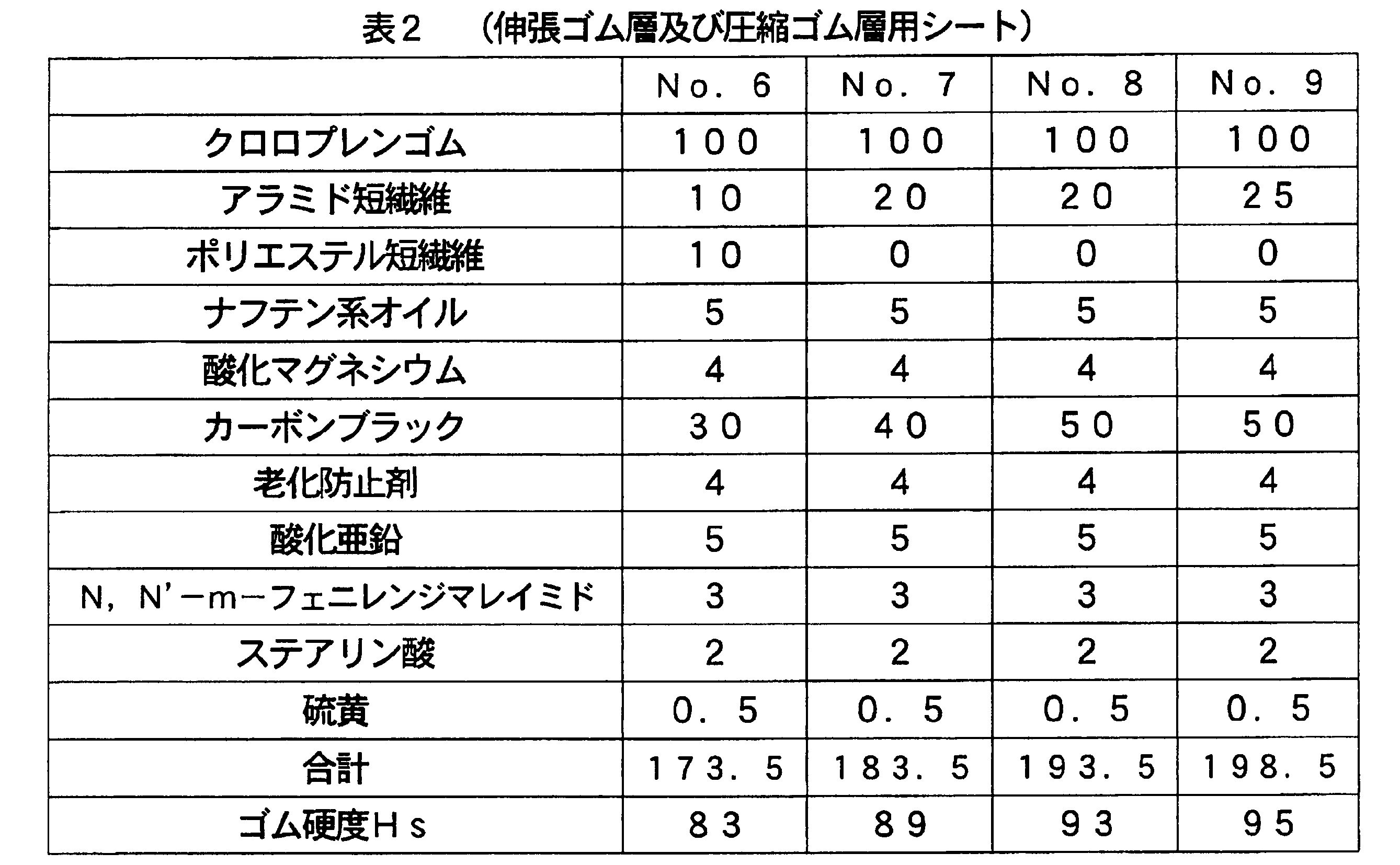
そして、表1に示す接着ゴム層用シートと、表2に示す圧縮ゴム層及び伸張ゴム層用シートとを、表3に示す組み合わせで積層し、圧縮ゴム層とコグとが一体に形成された伝動用Vベルトを作製した。すなわち、凸部と凹部とが交互に配された平坦なコグ付き型に、圧縮ゴム層用未加硫ゴムシートを接触させて加熱下でプレスし、コグ部が形成された半加硫状態のコグパッドを調製し、円筒状の金型に凸部と凹部とが交互に配された内母型を被せ、前記コグパッドを前記内母型に巻き付けて両端部をジョイントして装着し、装着したコグパッドに、第1の接着ゴムシート(未加硫ゴムシート)を巻き付け、心線をスピニングして芯体を形成した後、第2の接着ゴムシート(未加硫ゴムシート)と伸張ゴム層用シート(未加硫ゴムシート)と補強布(上布)とを順次に巻き付けて成形体を形成し、この成形体にジャケットを被せて加硫し、生成したベルトスリーブをV字状に切断加工し、コグ付き伝動用Vベルトを作製した。なお、比較例では、接着ゴム層を同じ種類の2枚の第1の接着ゴムシート(又は第2の接着ゴムシート)を用いて形成した。
And the sheet | seat for adhesion rubber layers shown in Table 1, and the sheet | seat for compression rubber layers and an expansion | extension rubber layer shown in Table 2 were laminated | stacked by the combination shown in Table 3, and the compression rubber layer and the cog were integrally formed. A transmission V-belt was produced. That is, the unvulcanized rubber sheet for the compressed rubber layer is brought into contact with a flat cogged mold in which convex portions and concave portions are alternately arranged and pressed under heating, in a semi-vulcanized state in which the cog portion is formed. A cog pad is prepared, a cylindrical mold is covered with an inner mother die in which convex portions and concave portions are alternately arranged, the cog pad is wound around the inner mother die, and both end portions are jointed and attached. First, a first adhesive rubber sheet (unvulcanized rubber sheet) is wound, and a core is formed by spinning a core wire, and then a second adhesive rubber sheet (unvulcanized rubber sheet) and a stretch rubber layer sheet (Unvulcanized rubber sheet) and reinforcing fabric (upper fabric) are wound in order to form a molded body, this molded body is covered with a jacket, vulcanized, and the resulting belt sleeve is cut into a V shape. A V-belt for transmission with cogs was produced. In the comparative example, the adhesive rubber layer was formed using two first adhesive rubber sheets (or second adhesive rubber sheets) of the same type.
得られた伝動用Vベルトの評価結果を表3、並びに図6及び図7に示す。なお、表3に記載のベルト厚みは、コグを含めたベルト全体の厚み(伸張ゴム層の表面からコグ山部の頂点に至る厚み)を意味する。
The evaluation results of the obtained transmission V-belt are shown in Table 3 and FIGS. The belt thickness described in Table 3 means the thickness of the entire belt including the cogs (thickness from the surface of the stretched rubber layer to the apex of the cog crest).
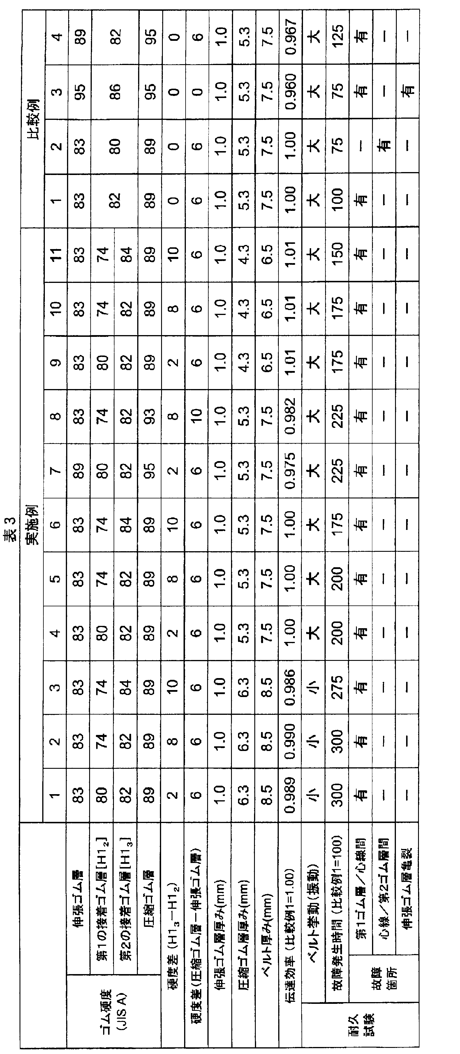
表3から明らかなように、従来の代表的な伝動用Vベルトに相当する比較例1では耐久性が十分でなく、比較例2では接着ゴム層のゴム硬度が低いためか、耐久性が低下するとともに、接着ゴム層において心線と下側(圧縮ゴム層側)のゴムとの間で剥離が発生した。また、特許文献1に相当する比較例3では、接着ゴム層のゴム硬度が高いためか、接着ゴム層において心線と上側(伸張ゴム層側)のゴムとの間で剥離が生じるとともに、伸張ゴム層に亀裂も発生し、伝達効率も改善できなかった。さらに、特許文献2に相当する比較例4では、伸張ゴム層及び圧縮ゴム層を高硬度化すると、故障は改善されたものの、伝達効率を十分に改善できなかった。このように、接着ゴム層を単一のゴム層とした伝動用Vベルトでは、ゴム硬度を調整しても、耐久性を向上しつつ伝達効率を改善できず、心線と接着ゴム層との剥離、伸張ゴム層の亀裂が生じる。特に、ベルト振動が大きい場合、心線と上側(伸張ゴム層側)のゴムとの間で剥離が早期発生する。
As is apparent from Table 3, the durability of Comparative Example 1 corresponding to a conventional representative V-belt for transmission is not sufficient, and in Comparative Example 2, the rubber hardness of the adhesive rubber layer is low. In addition, peeling occurred between the core wire and the lower rubber (compressed rubber layer side) in the adhesive rubber layer. Further, in Comparative Example 3 corresponding to Patent Document 1, because the rubber hardness of the adhesive rubber layer is high, peeling occurs between the core wire and the rubber on the upper side (extension rubber layer side) in the adhesive rubber layer. Cracks occurred in the rubber layer, and the transmission efficiency could not be improved. Furthermore, in Comparative Example 4 corresponding to Patent Document 2, when the hardness of the stretched rubber layer and the compressed rubber layer was increased, the failure was improved, but the transmission efficiency could not be sufficiently improved. As described above, in the transmission V-belt in which the adhesive rubber layer is a single rubber layer, even if the rubber hardness is adjusted, the transmission efficiency cannot be improved while improving the durability. Peeling and cracking of the stretched rubber layer occur. In particular, when the belt vibration is large, peeling occurs between the core wire and the upper rubber (extended rubber layer side) at an early stage.
これに対して、実施例1~11では、接着ゴム層のゴム硬度の分布を調整する(心線よりも上側(伸張ゴム層側)の第1のゴム層を低硬度化する)ことにより、ベルトの厚みが小さくても、伝達効率を改善しつつ耐久性を大きく向上できる。特に、心線と下側(圧縮ゴム層側)のゴムとの間での耐剥離性を確保しつつ、心線と上側(伸張ゴム層側)のゴムとの間での剥離が発生するまでの時間を約2倍以上遅延させることができ、耐久性を大きく改善できる。
On the other hand, in Examples 1 to 11, by adjusting the rubber hardness distribution of the adhesive rubber layer (by reducing the hardness of the first rubber layer on the upper side (stretched rubber layer side) of the core wire), Even if the thickness of the belt is small, the durability can be greatly improved while improving the transmission efficiency. In particular, until peeling occurs between the core wire and the rubber on the upper side (stretch rubber layer side) while ensuring the peel resistance between the core wire and the rubber on the lower side (compressed rubber layer side) Can be delayed about twice or more, and the durability can be greatly improved.
本発明を詳細に、また特定の実施態様を参照して説明したが、本発明の精神と範囲を逸脱することなく、様々な修正や変更を加えることができることは、当業者にとって明らかである。
本出願は、2016年7月22日出願の日本特許出願2016-144298、及び2017年7月13日付出願の日本特許出願2017-136697に基づくものであり、その内容はここに参照として取り込まれる。 Although the invention has been described in detail and with reference to specific embodiments, it will be apparent to those skilled in the art that various modifications and variations can be made without departing from the spirit and scope of the invention.
This application is based on Japanese Patent Application No. 2016-144298 filed on July 22, 2016 and Japanese Patent Application No. 2017-136697 filed on July 13, 2017, the contents of which are incorporated herein by reference.
本発明の伝動用Vベルトは、例えば、Vベルト(ラップドVベルト、ローエッジVベルト、ローエッジコグドVベルト)、Vリブドベルトなどに適用できる。特に、ベルト走行中に変速比が無段階で変わる変速機(無段変速装置)に使用されるVベルト(変速ベルト)、例えば、自動二輪車やATV(四輪バギー)、スノーモービルなどの無段変速装置に使用されるローエッジコグドVベルト、ローエッジダブルコグドVベルトに適用するのが好ましい。
The transmission V belt of the present invention can be applied to, for example, a V belt (wrapped V belt, low edge V belt, low edge cogged V belt), a V-ribbed belt, and the like. In particular, a V-belt (transmission belt) used in a transmission (continuously variable transmission) in which the gear ratio changes steplessly during belt travel, such as a motorcycle, an ATV (four-wheel buggy), a snowmobile, etc. The present invention is preferably applied to a low edge cogged V belt and a low edge double cogged V belt used in a transmission.
1…伝動用Vベルト
2,6…補強布
3…伸張ゴム層
4…接着ゴム層
4a…芯体
5…圧縮ゴム層 DESCRIPTION OFSYMBOLS 1 ... Transmission V belt 2,6 ... Reinforcement cloth 3 ... Stretch rubber layer 4 ... Adhesive rubber layer 4a ... Core body 5 ... Compression rubber layer
2,6…補強布
3…伸張ゴム層
4…接着ゴム層
4a…芯体
5…圧縮ゴム層 DESCRIPTION OF
Claims (10)
- 芯体と、芯体の少なくとも一部が埋設された接着ゴム層と、この接着ゴム層を介して積層された伸張ゴム層及び圧縮ゴム層とを備えた伝動用Vベルトであって、
前記伸張ゴム層のゴム硬度が、圧縮ゴム層のゴム硬度よりも小さく、
前記接着ゴム層において、芯体よりも伸張ゴム層側のゴム硬度が、圧縮ゴム層側のゴム硬度よりも小さい伝動用Vベルト。 A transmission V-belt comprising a core, an adhesive rubber layer in which at least a part of the core is embedded, and an extension rubber layer and a compression rubber layer laminated via the adhesive rubber layer,
The rubber hardness of the stretch rubber layer is smaller than the rubber hardness of the compression rubber layer,
In the adhesive rubber layer, a transmission V-belt in which the rubber hardness on the stretched rubber layer side is smaller than the rubber hardness on the compressed rubber layer side than the core body. - 厚みが6.5~8.5mmである請求項1記載の伝動用Vベルト。 The transmission V-belt according to claim 1, wherein the thickness is 6.5 to 8.5 mm.
- 前記接着ゴム層のゴム硬度が74~85°の範囲であり、前記接着ゴム層において、伸張ゴム層側と圧縮ゴム層側とのゴム硬度の差が2~12°である請求項1又は2記載の伝動用Vベルト。 The rubber hardness of the adhesive rubber layer is in the range of 74 to 85 °, and the difference in rubber hardness between the stretched rubber layer side and the compressed rubber layer side in the adhesive rubber layer is 2 to 12 °. The transmission V-belt described.
- 前記接着ゴム層が、複数のゴム層で形成され、伸張ゴム層と接する第1の接着ゴム層のゴム硬度が74~82°であり、圧縮ゴム層と接する第2の接着ゴム層のゴム硬度が77~85°であり、第1の接着ゴム層と第2の接着ゴム層とのゴム硬度の差が2~10°である請求項1~3のいずれか一項に記載の伝動用Vベルト。 The adhesive rubber layer is formed of a plurality of rubber layers, the rubber hardness of the first adhesive rubber layer in contact with the stretch rubber layer is 74 to 82 °, and the rubber hardness of the second adhesive rubber layer in contact with the compression rubber layer The transmission V according to any one of claims 1 to 3, wherein the difference in rubber hardness between the first adhesive rubber layer and the second adhesive rubber layer is 2 to 10 °. belt.
- 前記伸張ゴム層のゴム硬度が83~89°の範囲であり、
前記圧縮ゴム層のゴム硬度が89~95°の範囲であり、両者のゴム硬度の差が3~10°である請求項1~4のいずれか一項に記載の伝動用Vベルト。 The stretch rubber layer has a rubber hardness in the range of 83 to 89 °;
The transmission V-belt according to any one of claims 1 to 4, wherein the compression rubber layer has a rubber hardness in a range of 89 to 95 °, and a difference in rubber hardness between the two is 3 to 10 °. - 少なくとも内周面側にコグを有する請求項1~5のいずれか一項に記載の伝動用Vベルト。 The transmission V-belt according to any one of claims 1 to 5, which has a cog on at least the inner peripheral surface side.
- 前記伸張ゴム層及び圧縮ゴム層の少なくとも一方に積層された補強布層を備え、各ゴム層の両側面が露出している請求項1~6のいずれか一項に記載の伝動用Vベルト。 The transmission V-belt according to any one of claims 1 to 6, further comprising a reinforcing cloth layer laminated on at least one of the stretched rubber layer and the compressed rubber layer, wherein both side surfaces of each rubber layer are exposed.
- 前記伸張ゴム層及び圧縮ゴム層が、クロロプレンゴム100質量部に対して、カーボンブラック25~60質量部、短繊維15~30質量部、金属酸化物加硫剤1~20質量部、及びビスマレイミド類2~5質量部を含むゴム組成物でそれぞれ形成され、カーボンブラック、ビスマレイミド類及び短繊維から選択された少なくとも一種の成分が、伸張ゴム層よりも圧縮ゴム層に多くの割合で含まれている請求項1~7のいずれか一項に記載の伝動用Vベルト。 The stretch rubber layer and the compression rubber layer are 25 to 60 parts by mass of carbon black, 15 to 30 parts by mass of short fibers, 1 to 20 parts by mass of a metal oxide vulcanizing agent, and bismaleimide with respect to 100 parts by mass of chloroprene rubber. Each of which is formed of a rubber composition containing 2 to 5 parts by mass of at least one component selected from carbon black, bismaleimides and short fibers, and is contained in a larger proportion in the compressed rubber layer than in the stretched rubber layer. The transmission V-belt according to any one of claims 1 to 7.
- 前記接着ゴム層が、クロロプレンゴム100質量部に対して、カーボンブラック25~50質量部、シリカ10~30質量部、金属酸化物加硫剤1~20質量部及びビスマレイミド類0.5~5質量部を含むゴム組成物で形成され、カーボンブラック、シリカ及びビスマレイミド類から選択された少なくとも一種の成分が、圧縮ゴム層側よりも伸張ゴム層側に少ない割合で含まれている請求項1~8のいずれか一項に記載の伝動用Vベルト。 The adhesive rubber layer comprises 25 to 50 parts by mass of carbon black, 10 to 30 parts by mass of silica, 1 to 20 parts by mass of a metal oxide vulcanizing agent, and 0.5 to 5 bismaleimides with respect to 100 parts by mass of chloroprene rubber. 2. The rubber composition comprising a mass part, wherein at least one component selected from carbon black, silica and bismaleimides is contained in a smaller proportion on the stretched rubber layer side than on the compressed rubber layer side. The transmission V-belt according to any one of 1 to 8.
- 変速ベルトである請求項1~9のいずれか一項に記載の伝動用Vベルト。 The transmission V-belt according to any one of claims 1 to 9, which is a transmission belt.
Priority Applications (4)
| Application Number | Priority Date | Filing Date | Title |
|---|---|---|---|
| US16/319,127 US11421752B2 (en) | 2016-07-22 | 2017-07-20 | Transmission V-belt |
| CN201780044876.8A CN109477548B (en) | 2016-07-22 | 2017-07-20 | V-belt for transmission |
| EP17831073.6A EP3489544B1 (en) | 2016-07-22 | 2017-07-20 | Transmission v-belt |
| ES17831073T ES2912372T3 (en) | 2016-07-22 | 2017-07-20 | Transmission V-belt |
Applications Claiming Priority (4)
| Application Number | Priority Date | Filing Date | Title |
|---|---|---|---|
| JP2016144298 | 2016-07-22 | ||
| JP2016-144298 | 2016-07-22 | ||
| JP2017136697A JP6616808B2 (en) | 2016-07-22 | 2017-07-13 | V-belt for transmission |
| JP2017-136697 | 2017-07-13 |
Publications (1)
| Publication Number | Publication Date |
|---|---|
| WO2018016557A1 true WO2018016557A1 (en) | 2018-01-25 |
Family
ID=60992536
Family Applications (1)
| Application Number | Title | Priority Date | Filing Date |
|---|---|---|---|
| PCT/JP2017/026197 WO2018016557A1 (en) | 2016-07-22 | 2017-07-20 | Transmission v-belt |
Country Status (3)
| Country | Link |
|---|---|
| EP (1) | EP3489544B1 (en) |
| ES (1) | ES2912372T3 (en) |
| WO (1) | WO2018016557A1 (en) |
Cited By (1)
| Publication number | Priority date | Publication date | Assignee | Title |
|---|---|---|---|---|
| WO2023153405A1 (en) * | 2022-02-14 | 2023-08-17 | デンカ株式会社 | Rubber composition, vulcanizate, and vulcanized molded body |
Families Citing this family (2)
| Publication number | Priority date | Publication date | Assignee | Title |
|---|---|---|---|---|
| JP6616852B2 (en) * | 2017-02-27 | 2019-12-04 | 三ツ星ベルト株式会社 | Transmission belt |
| JP6567210B1 (en) | 2018-05-25 | 2019-08-28 | 三ツ星ベルト株式会社 | Wrapped V belt |
Citations (3)
| Publication number | Priority date | Publication date | Assignee | Title |
|---|---|---|---|---|
| JPH0554851U (en) * | 1991-12-25 | 1993-07-23 | 三ツ星ベルト株式会社 | Power transmission belt |
| JPH10238596A (en) * | 1997-02-26 | 1998-09-08 | Bando Chem Ind Ltd | Belt for power transmission |
| JP2009150538A (en) * | 2007-11-30 | 2009-07-09 | Mitsuboshi Belting Ltd | Cogged v-belt |
Family Cites Families (2)
| Publication number | Priority date | Publication date | Assignee | Title |
|---|---|---|---|---|
| JP2004211755A (en) * | 2002-12-27 | 2004-07-29 | Bando Chem Ind Ltd | Cogged v belt |
| JP6055430B2 (en) * | 2013-03-29 | 2016-12-27 | 三ツ星ベルト株式会社 | Transmission belt |
-
2017
- 2017-07-20 WO PCT/JP2017/026197 patent/WO2018016557A1/en unknown
- 2017-07-20 ES ES17831073T patent/ES2912372T3/en active Active
- 2017-07-20 EP EP17831073.6A patent/EP3489544B1/en active Active
Patent Citations (3)
| Publication number | Priority date | Publication date | Assignee | Title |
|---|---|---|---|---|
| JPH0554851U (en) * | 1991-12-25 | 1993-07-23 | 三ツ星ベルト株式会社 | Power transmission belt |
| JPH10238596A (en) * | 1997-02-26 | 1998-09-08 | Bando Chem Ind Ltd | Belt for power transmission |
| JP2009150538A (en) * | 2007-11-30 | 2009-07-09 | Mitsuboshi Belting Ltd | Cogged v-belt |
Non-Patent Citations (1)
| Title |
|---|
| See also references of EP3489544A4 * |
Cited By (1)
| Publication number | Priority date | Publication date | Assignee | Title |
|---|---|---|---|---|
| WO2023153405A1 (en) * | 2022-02-14 | 2023-08-17 | デンカ株式会社 | Rubber composition, vulcanizate, and vulcanized molded body |
Also Published As
| Publication number | Publication date |
|---|---|
| EP3489544B1 (en) | 2022-04-06 |
| ES2912372T3 (en) | 2022-05-25 |
| EP3489544A1 (en) | 2019-05-29 |
| EP3489544A4 (en) | 2020-03-25 |
Similar Documents
| Publication | Publication Date | Title |
|---|---|---|
| JP6616808B2 (en) | V-belt for transmission | |
| JP6055430B2 (en) | Transmission belt | |
| JP5727442B2 (en) | Transmission belt | |
| WO2012161141A1 (en) | Power transmission belt | |
| US20190390047A1 (en) | Transmission Belt | |
| CA3053901C (en) | Transmission belt | |
| WO2017110784A1 (en) | Friction drive belt | |
| JP6483745B2 (en) | Friction transmission belt | |
| WO2018016557A1 (en) | Transmission v-belt | |
| JP6809985B2 (en) | Friction transmission belt | |
| WO2017110790A1 (en) | Friction-transmission belt and method for manufacturing same | |
| JP6650388B2 (en) | Friction transmission belt | |
| JP6616793B2 (en) | Friction transmission belt | |
| JP6747924B2 (en) | Friction transmission belt and manufacturing method thereof | |
| JP6567210B1 (en) | Wrapped V belt | |
| WO2017179688A1 (en) | Friction transmission belt | |
| JP7189381B2 (en) | V-belt for power transmission | |
| WO2024004769A1 (en) | Rubber composition for transmission belt, transmission belt, and method for manufacturing transmission belt | |
| WO2017179690A1 (en) | Friction transmission belt | |
| WO2022176577A1 (en) | Transmission v-belt | |
| JP2024022495A (en) | Rubber composition for power transmission belts and power transmission belts | |
| JP2022003268A (en) | Transmission v-belt |
Legal Events
| Date | Code | Title | Description |
|---|---|---|---|
| 121 | Ep: the epo has been informed by wipo that ep was designated in this application |
Ref document number: 17831073 Country of ref document: EP Kind code of ref document: A1 |
|
| NENP | Non-entry into the national phase |
Ref country code: DE |
|
| ENP | Entry into the national phase |
Ref document number: 2017831073 Country of ref document: EP Effective date: 20190222 |