WO2018016292A1 - 鉄鉱石の鉄品位向上方法 - Google Patents
鉄鉱石の鉄品位向上方法 Download PDFInfo
- Publication number
- WO2018016292A1 WO2018016292A1 PCT/JP2017/023998 JP2017023998W WO2018016292A1 WO 2018016292 A1 WO2018016292 A1 WO 2018016292A1 JP 2017023998 W JP2017023998 W JP 2017023998W WO 2018016292 A1 WO2018016292 A1 WO 2018016292A1
- Authority
- WO
- WIPO (PCT)
- Prior art keywords
- iron
- iron ore
- reducing gas
- gangue
- reduction
- Prior art date
- Legal status (The legal status is an assumption and is not a legal conclusion. Google has not performed a legal analysis and makes no representation as to the accuracy of the status listed.)
- Ceased
Links
Images

Classifications
-
- C—CHEMISTRY; METALLURGY
- C21—METALLURGY OF IRON
- C21B—MANUFACTURE OF IRON OR STEEL
- C21B13/00—Making spongy iron or liquid steel, by direct processes
-
- C—CHEMISTRY; METALLURGY
- C22—METALLURGY; FERROUS OR NON-FERROUS ALLOYS; TREATMENT OF ALLOYS OR NON-FERROUS METALS
- C22B—PRODUCTION AND REFINING OF METALS; PRETREATMENT OF RAW MATERIALS
- C22B1/00—Preliminary treatment of ores or scrap
-
- C—CHEMISTRY; METALLURGY
- C22—METALLURGY; FERROUS OR NON-FERROUS ALLOYS; TREATMENT OF ALLOYS OR NON-FERROUS METALS
- C22B—PRODUCTION AND REFINING OF METALS; PRETREATMENT OF RAW MATERIALS
- C22B1/00—Preliminary treatment of ores or scrap
- C22B1/02—Roasting processes
- C22B1/04—Blast roasting
-
- C—CHEMISTRY; METALLURGY
- C22—METALLURGY; FERROUS OR NON-FERROUS ALLOYS; TREATMENT OF ALLOYS OR NON-FERROUS METALS
- C22B—PRODUCTION AND REFINING OF METALS; PRETREATMENT OF RAW MATERIALS
- C22B5/00—General methods of reducing to metals
- C22B5/02—Dry methods smelting of sulfides or formation of mattes
- C22B5/12—Dry methods smelting of sulfides or formation of mattes by gases
Definitions
- the present invention relates to a method for improving iron quality by carrying out pulverization and magnetic separation after reduction of iron ore in order to use iron ore with low iron quality as an iron production raw material.
- Patent Documents 1 to 7 disclose techniques for improving the iron quality of iron ore by removing gangue.
- Patent Document 1 manufactures high-purity, high-density reduced iron by cooling, finely pulverizing, magnetically sorting, and re-molding reduced iron obtained in a reduced iron production facility using coal as a reducing agent.
- the purpose is to do. Specifically, the reduced iron obtained by heating and reducing the mixture containing the iron raw material and coal at a high temperature is pulverized, and then the particle size is selected with a predetermined particle size as a boundary.
- the reduced iron particles are separated into strong magnetic particles containing a large amount of iron and weakly magnetic particles having a small amount of iron by magnetic force, and then the reduced iron particles exceeding the predetermined particle size and the strong magnetic material are separated by particle size selection. The particles are used as reduced iron.
- Patent Document 2 aims to produce metallic iron with high iron purity by magnetic separation after reducing an agglomerate containing an iron oxide-containing substance and a carbonaceous reducing agent. Specifically, when a material to be heated obtained by heat reduction treatment of a mixture containing iron raw material and coal at high temperature is separated into metallic iron and slag using a first magnetic separator, a transport mechanism is used as a magnetic separator. And a device in which the magnetic field intensity in the magnetic field generation region has an inflection point along the flow direction of the object to be heated.
- Patent Document 3 aims to produce iron carbide efficiently in a short time by preventing the formation of free carbon without increasing the sulfur concentration in the product in producing iron carbide from an iron oxide-containing substance. Specifically, when reducing iron oxide-containing materials and carbonizing them to produce iron carbide, the molar ratio of sulfur to the sum of the molar concentrations of H 2 and CO (S / H 2 + CO) is Fe / FeS equilibrium. The iron oxide-containing substance is reduced with a reducing gas containing S that is 0.05 times to less than 1 time the molar ratio of sulfur at the time, and the prereduced product with iron carbide less than 20 mass% and metallization rate of 60% or more The prereduced product is carbonized with a carbonizing gas to produce iron carbide.
- Patent document 4 aims at suppressing the reduction
- Patent document 5 aims at improving the separability of reduced iron and slag with respect to reduced iron and slag obtained in a semi-molten state in which all of the agglomerates are not completely melted. Specifically, the step of agglomerating the raw material agglomerate further blended with the iron oxide-containing substance and the carbonaceous material and a melting point adjuster, and heating so that a part of the obtained agglomerate melts, And reducing the iron oxide contained in the agglomerate in this order.
- the agglomerate is heated below the temperature at which it completely melts, the melting point modifier contains at least a CaO supply substance, CaO / SiO 2 of the agglomerate is 0.2 to 0.9, and the blending amount of the melting point modifier is adjusted.
- the melting amount of gangue contained in the agglomerate at a temperature subtracted by 100 ° C. from the maximum temperature when the agglomerate is heated is set to 50% by mass or more.
- Patent Document 6 aims to improve the productivity of metallic iron and solve the problem of reoxidation in the operation of a direct reduction apparatus. Specifically, when iron ore is reduced with a reducing gas containing hydrogen and / or carbon monoxide, the ore supply / discharge rate is adjusted so that the metallization rate of the semi-reduced ore is 10% to 80%. We are going to adjust.
- Patent Document 7 describes the case where gangue is dissolved in iron oxide (iron ore), where the effect of beneficiation cannot be expected by conventional beneficiation techniques such as magnetic ore flotation (magnetic separation) and flotation (flotation).
- An object of the present invention is to provide a technique for efficiently removing gangue even when fine gangue particles are dispersed in iron ore. Specifically, when removing gangue, iron oxide is reduced by carbonaceous material internal reduction to form metallic iron, and the metallic iron is crushed and magnetically selected.
- JP 2002-363624 A JP 2016-14184 A JP-A-10-291816 JP 2014-1111813 A JP 2013-127112 A JP-A-9-165612 Japanese Patent Laying-Open No. 2015-101740
- grains which are the objects of magnetic ore separation is as fine as 100 micrometers or less.
- the premise of this document is that the heating at 1200 ° C or higher is necessary for the carbonaceous material reduction, and it is necessary to add a flux in order to melt the gangue. Therefore, there is a possibility that the amount of slag increases, and it is difficult to say that this is an efficient method for producing reduced iron.
- Patent Document 2 is a technique suitable for producing metallic iron, but it is only disclosed that the pulverized particle size is 10 mm or less, and it is considered that a pulverized particle size is included. Moreover, since the premise of the same document is carbonaceous material internal reduction, heating at 1200 ° C. or higher is necessary, and addition of flux is necessary to melt the gangue. This flux becomes an impurity like gangue. In this document, it is recommended that the heating temperature be 1400 to 1480 ° C.
- Patent Document 3 is considered to be very difficult to improve the iron quality of iron ore because the purpose is the production of iron carbide and it does not have a pulverization step and a subsequent magnetic separation step.
- Patent Document 4 is a gas reduction technique, the purpose is only to improve productivity in the reduction treatment of iron ore, and since there is no grinding step and subsequent magnetic separation step, the iron grade of iron ore is reduced. It seems very difficult to improve.
- Patent Document 5 is a technique suitable for producing a mixture of reduced iron and slag, but it only discloses that the pulverized particle size is 3 mm or less, so that the pulverized particle size is small. Can be considered. Moreover, since the premise of this document is carbonaceous material internal reduction, heating at 1200 ° C. or higher is required, and furthermore, addition of flux is required to melt a part. This flux becomes an impurity like gangue.
- Patent Document 6 is a gas reduction technique, the purpose is only to improve productivity in the reduction treatment of iron ore, and since there is no grinding step and subsequent magnetic separation step, the iron grade of iron ore is reduced. It seems very difficult to improve.
- patent document 7 is a technique which reduces iron ore, it is carbonaceous interior reduction, and since S in the carbonaceous material penetrates into iron, even if the iron quality can be improved, Is difficult to use, and there is a problem that the cost is very large for desulfurization. Moreover, it is necessary to heat iron oxide to 1000 degreeC or more, and there exists a possibility that the cost regarding operation and an installation may start very much.
- the present invention can efficiently remove gangue contained in iron ore to improve iron quality, and does not employ a carbonaceous material interior and is easy to use as a raw material for iron making. It is an object of the present invention to provide a method for improving the iron quality of iron ore.
- the method for improving the iron quality of iron ore according to the present invention is to remove the gangue by pulverizing the iron ore containing the gangue after performing reduction treatment with a reducing gas, and then performing magnetic separation.
- the reduction time [min] of the iron ore is t
- the H 2 partial pressure [atm] of the reducing gas is P H2
- the CO partial pressure of the reducing gas [atm ] the when the P CO, parameter X represented by a function of reduction time and the reducing gas partial pressure of the iron ore, to satisfy equation (1), and controls the reduction treatment .
- another iron ore iron quality improvement method is to reduce the iron ore with Ig loss ⁇ 10 wt% by H 2 gas so that the metallization rate ⁇ 60 wt%.
- the particle size of the iron ore after pulverization is set to D 50 ⁇ 100 ⁇ m. To do.
- the gangue contained in the iron ore can be efficiently removed to improve the iron quality, and at the same time, the form can be easily used as an iron making raw material.
- iron ore containing gangue is subjected to reduction treatment with a reducing gas and then pulverized, and then subjected to magnetic beneficiation to remove gangue, as the reducing gas, Reduction treatment is performed using H 2 gas and / or CO gas, the reduction time [min] of iron ore is set to t, the H 2 partial pressure [atm] of the reducing gas is set to P H2, and the CO partial pressure of the reducing gas [ atm] the when the P CO, parameter X is represented by a function of reduction time and reduction gas partial pressure of iron ore, to satisfy equation (1), by controlling the reduction treatment, to improve the iron ore grade
- the reducing gas is used to carry out the reducing treatment, and the reducing gas used for carrying out the reducing treatment contains at least one of H 2 and CO, or both.
- Gangue (Al 2 O 3 , SiO) contained in poor iron ore containing hydroxyl groups and carbonate groups such as FeOOH, Fe (OH) 2 , Fe (OH) 3 , FeCO 3 2 ) is separated and removed to form metallic iron (Fe).
- the reducing gas may contain an inert gas such as N 2 .
- the method described above is to generate metallic iron by a reduction treatment using a reducing gas and to preferentially collect the metallic iron by magnetic separation.
- the reduction treatment is insufficient, the yield of metallic iron that can be recovered by magnetic separation may deteriorate rapidly.
- the parameter X expressed as a function of the reduction time of the iron ore and the partial pressure of the reducing gas satisfies the above formula (1).
- the reduction process is controlled to improve the iron quality.
- the “iron recovery rate” is an index representing the proportion of metallic iron that can be recovered by magnetic separation, and the higher the value, the higher the recovery efficiency of metallic iron. In calculating the iron recovery rate, Equation (2) is used.
- T.Fe [wt%] is the total iron concentration contained in the iron ore
- T.Fe [wt%] before magnetic selection and “T.Fe [wt%] after magnetic selection”.
- a magnetic adhesion rate is represented by the following formula
- weight is the total weight of iron ore
- weight before magnetic separation and “weight after magnetic separation” are the total weight of iron ore before magnetic separation and magnetic separation, respectively. It is the total weight of the later iron ore.
- the reducing gas used in the reduction process is H 2 gas
- the metallization rate in the reduction process is 60 wt% or more
- the particle size is 2 in the pulverization performed after the reduction process. It is preferable that the diameter is not more than mm and the particle diameter after grinding is D 50 ⁇ 100 ⁇ m.
- iron ore containing gangue is subjected to reduction treatment with a reducing gas and then pulverized, and then subjected to magnetic beneficiation to remove gangue, thereby reducing H as a reducing gas.
- a reducing gas e.g., Ignition loss
- H 2 gas e.g., H 2 gas
- the particle size is 2 mm or less
- the particle size of the iron ore after pulverization is set to D 50 ⁇ 100 ⁇ m when the iron grade of the iron ore is improved by magnetic separation and magnetic selection thereafter (the method of the present invention). This is referred to as a second embodiment).
- the reducing gas used for carrying out the reduction treatment is H 2 gas, and a poor quality containing a hydroxyl group such as FeOOH, Fe (OH) 2 , Fe (OH) 3 , FeCO 3 is used. It is aimed at technology that forms metallic iron (Fe) by separating and removing gangue (Al 2 O 3 , SiO 2 etc.) contained in the iron ore.
- the H 2 gas may contain an inert gas such as N 2 and is a gas containing at least 50% of H 2 .
- the iron ore (iron oxide) to be reduced is subject to an Ig loss of 10% by weight or more.
- Ig loss is an abbreviation for Ignition loss and refers to the mass of volatile substances (OH groups) contained in iron oxide.
- Ig loss is high.
- IgIloss in iron ore it is measured by the method defined in JIS M 8700 8.4. That is, Ig loss is a mass change when iron ore is held at 1000 ° C., and excludes weight loss due to hygroscopic water. Hygroscopic water can be removed by heating at 105 ° C. for 2 hours.
- iron ore to be reduced with H 2 gas is reduced so that the metallization rate is 60 wt% or more.
- the metallization rate can be adjusted as appropriate according to the type and amount of iron ore to be reduced and the nature of the H 2 gas used.
- Metallization rate is an index generally used to indicate the degree of reduction of iron ore.
- Equation (4) “M.Fe [wt%]” is the concentration of metallic iron, and “T.Fe [wt%]” is the total iron concentration.
- the gangue removal rate is an index indicating how much the gangue is removed from the original iron ore. The higher the derived value, the better the gangue is removed. In calculating the gangue removal rate, the following equation (5) is used.
- ore gangue rate is the gangue rate of the original iron ore
- post-magnetization gangue rate is the gangue rate of iron ore after magnetic separation. Further, the gangue rate is defined as shown in Equation (6) below.
- SiO 2 [wt%] and Al 2 O 3 [wt%] are the concentrations of SiO 2 and Al 2 O 3 contained in the steel stone, respectively.
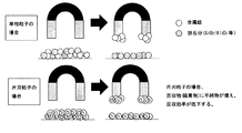
- the inventors have made the pulverized particle size too small, that is, if there are finely pulverized particles, they are easily affected by static electricity, and the particles tend to aggregate. It has been found that the removal efficiency decreases.
- the iron ore after reduction has a particle diameter of 2 mm or less, and further, the particle diameter (median diameter) D 50 after pulverization, in other words, the median diameter is 100 ⁇ m or more ( D 50 ⁇ 100 ⁇ m), and then the magnetic separation is performed to improve the gangue removal efficiency.
- any method that can remove particles below the set lower limit when the iron ore particle size (median diameter) D 50 after grinding the iron ore to a particle size of 2 mm or less is not 100 ⁇ m or more,
- D 50 ⁇ 100 ⁇ m can be obtained by using a conventional method such as sieving.
- D 50 [ ⁇ m] refers to the particle size of a value that takes 50% of the volume from the smaller particle. This value can be easily obtained with a laser diffraction particle size analyzer such as a microtrack.
- Experimental Example 1 First, implementation conditions of Experimental Example 1 according to the first embodiment of the present invention will be described.
- Experimental Example 1 three types of ores shown in Table 1 were used as the ores used in the iron ore iron quality improvement method.
- the reduction treatment was performed as shown below. 1) It was carried out at 950 ° C. using a horizontal resistance furnace. 2) As the reducing gas, various mixed gases were used in which the ratio of H 2 : N 2 : CO showed the partial pressure described in the reducing conditions in Table 2. 3) The amount of iron ore sample during the reduction treatment was 50 g per channel (charge), and the flow rate of the reducing gas was 3 Nl / min.
- the iron ore crushing method and the particle size measurement of the iron ore after crushing were performed as follows. 1) The iron ore after reduction was pulverized using a disk mill to a particle size of 2 mm or less. 2) The particle size measurement of the iron ore after pulverization was carried out using a laser diffraction particle size analyzer.
- Magnetic selection was performed using a hand-type magnetic separator with a magnetic field strength of 200 G.
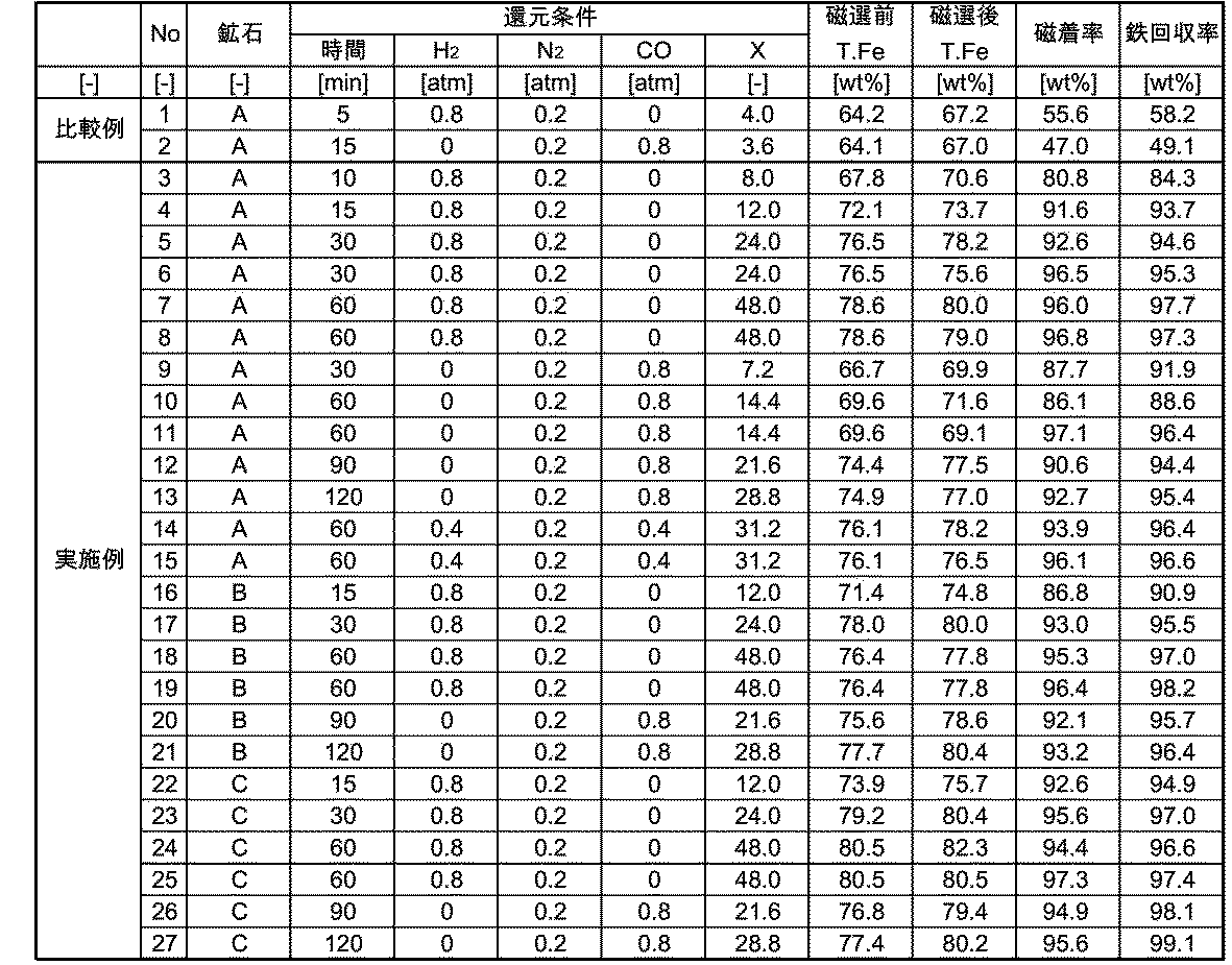
- No. 1 and No. 2 in Table 2 are comparative examples conducted for comparison with the inventive examples.
- Nos. 3 to 27 in Table 2 are examples carried out according to the iron grade improving method for iron ore according to the first embodiment of the present invention.
- the reduction time t of the iron ore is 5 [min]
- the H 2 partial pressure P H2 of the reducing gas is 0.8 [atm]
- the N 2 partial pressure P N2 of the reducing gas is 0.2 [atm].
- the parameter X is 4.0 [ ⁇ ], which does not satisfy the expression (1).
- T.Fe before magnetic separation is 64.2 [wt%]
- T.Fe after magnetic separation is 67.2 [wt%]
- the magnetic adhesion rate is 55.6 [wt%].
- the iron recovery rate was 58.2 [wt%], which was very inefficient.
- the reduction time t of iron ore is 10 [min]
- the H 2 partial pressure P H2 of the reducing gas is 0.8 [atm]
- the N 2 partial pressure P N2 of the reducing gas is 0.2 [atm].
- the parameter X is 8.0 [ ⁇ ], which satisfies Expression (1) (X ⁇ 5).
- T.Fe before magnetic separation is 67.8 [wt%]
- T.Fe after magnetic separation is 70.6 [wt%]
- the magnetic adhesion rate is 80.8 [wt%].
- the iron recovery rate was 84.3 [wt%]
- the efficiency was very good.
- the reduction time t of iron ore is 60 [min]
- the H 2 partial pressure P H2 of the reducing gas is 0.8 [atm]
- the N 2 partial pressure P N2 of the reducing gas is 0.2 [atm].
- the parameter X is 48.0 [ ⁇ ], which satisfies Expression (1) (X ⁇ 5).
- T.Fe before magnetic separation is 78.6 [wt%]
- T.Fe after magnetic separation is 80.0 [wt%]
- the magnetic adhesion rate is 96.0 [wt%].
- the iron recovery rate was 97.7 [wt%], and the efficiency was very good.
- the reduction time t of iron ore is 60 [min]
- the H 2 partial pressure P H2 of the reducing gas is 0.4 [atm]
- the N 2 partial pressure P N2 of the reducing gas is 0.2 [atm]
- the CO partial pressure P CO of the reducing gas is 0.4 [atm].
- the parameter X is 31.2 [ ⁇ ], which satisfies Expression (1) (X ⁇ 5).
- T.Fe before magnetic separation is 76.1 [wt%]
- T.Fe after magnetic separation is 78.2 [wt%]
- the magnetic adhesion rate is 93.9 [wt%].
- the iron recovery rate was 96.4 [wt%], which was very efficient.
- the reduction time t of iron ore is 60 [min]
- the H 2 partial pressure P H2 of the reducing gas is 0.8 [atm]
- the N 2 partial pressure P N2 of the reducing gas is 0.2 [atm].
- the parameter X is 48.0 [ ⁇ ], which satisfies Expression (1) (X ⁇ 5).
- the T.Fe before magnetic separation is 76.4 [wt%]
- the T.Fe after magnetic separation is 77.8 [wt%]
- the magnetic adhesion rate is 96.4 [wt%].
- the iron recovery rate was 98.2 [wt%]
- the efficiency was very good.
- the reduction time t of iron ore is 120 [min]
- the N 2 partial pressure P N2 of the reducing gas is 0.2 [atm]
- the CO partial pressure P CO of the reducing gas is 0.8 [ atm].
- the parameter X is 28.8 [ ⁇ ], which satisfies the expression (1) (X ⁇ 5).
- T.Fe before magnetic separation is 77.4 [wt%]
- T.Fe after magnetic separation is 80.2 [wt%]
- the magnetic adhesion rate is 95.6 [wt%].
- the iron recovery rate was 99.1 [wt%], which was very efficient.
- the iron recovery rate can be made high by controlling the reduction treatment so as to satisfy the formula (1) in the same manner as in the examples exemplified above.
- the first embodiment of the present invention is a technique that focuses on increasing the iron recovery efficiency, and according to this technique, an iron ore gangue with low T.Fe is efficiently used. By removing it well, it is possible to improve the iron quality and make it easy to use as a raw material for iron making.
- the reduction treatment was performed as shown below. 1) It was carried out at 950 ° C. using a horizontal resistance furnace. As 2) a reducing gas, H 2: 80%, N 2: with 20% of the proportion of H 2 gas. 3) The amount of iron ore sample during the reduction treatment was 50 g per channel (charge), and the flow rate of the reducing gas (H 2 gas) was 3 Nl / min.
- the iron ore crushing method and the particle size measurement of the iron ore after crushing were performed as follows. 1) The iron ore after reduction was pulverized using a disk mill to a particle size of 2 mm or less. 2) The iron ore after pulverization was sieved so that the particle size after pulverization was D 50 ⁇ 100 ⁇ m. 3) The particle size of the iron ore after pulverization was measured using a laser diffraction particle size analyzer.
- Magnetic selection was performed using a hand-type magnetic separator with a magnetic field strength of 200 G.
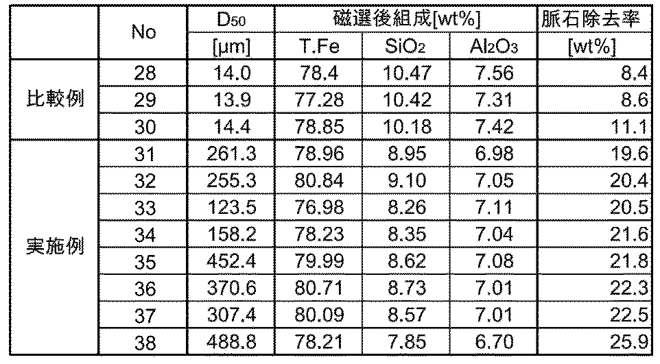
- the particle diameter D 50 after pulverization is 14.0 ⁇ m and does not satisfy the prescribed D 50 ⁇ 100 ⁇ m.
- the composition of the iron ore after magnetic separation is, T.Fe is 78.4 wt%, SiO 2 is 10.47 wt%, Al 2 O 3 is 7.56 wt%.
- the gangue removal efficiency was 8.4 wt%, which was very inefficient. That is, the iron ore after pulverization in No. 28 of the comparative example contains a lot of particles that are too fine, and due to the influence of static electricity, the fine particles agglomerate with each other. I understood that.
- Nos. 29 and 30 of the comparative example also had a very bad gangue removal efficiency because the particle size D 50 after pulverization did not satisfy the prescribed D 50 ⁇ 100 ⁇ m.
- the particle diameter D 50 after pulverization is 261.3 ⁇ m, which satisfies the prescribed D 50 ⁇ 100 ⁇ m.
- the composition of the iron ore after magnetic separation is, T.Fe is 78.96 wt%, SiO 2 is 8.95 wt%, Al 2 O 3 is 6.98 wt%.
- the gangue removal efficiency was 19.6 wt%, which was very good.
- the particle diameter D 50 after pulverization is 158.2 ⁇ m, and the prescribed D 50 ⁇ 100 ⁇ m is satisfied.
- the composition of the iron ore after magnetic separation is, T.Fe is 78.23 wt%, SiO 2 is 8.35 wt%, Al 2 O 3 is 7.04 wt%.
- the gangue removal efficiency was 21.6 wt%, which was very good.
- the particle diameter D 50 after pulverization is 488.8 ⁇ m, and the prescribed D 50 ⁇ 100 ⁇ m is satisfied.
- the composition of the iron ore after magnetic separation is, T.Fe is 78.21 wt%, SiO 2 is 7.85 wt%, Al 2 O 3 is 6.70 wt%.
- the gangue removal efficiency was 25.9 wt%, which was very good.
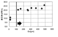
- the gangue removal efficiency could be made high by setting the particle size of the iron ore after pulverization to the specified D 50 ⁇ 100 ⁇ m. (See FIG. 3).
- the second embodiment of the present invention it is possible to improve the iron quality by efficiently removing the gangue of iron ore having a low T.Fe, and to use it as a raw material for iron making. It becomes possible to make it an easy form.
Landscapes
- Engineering & Computer Science (AREA)
- Chemical & Material Sciences (AREA)
- Manufacturing & Machinery (AREA)
- Materials Engineering (AREA)
- Metallurgy (AREA)
- Organic Chemistry (AREA)
- Mechanical Engineering (AREA)
- Life Sciences & Earth Sciences (AREA)
- Environmental & Geological Engineering (AREA)
- General Life Sciences & Earth Sciences (AREA)
- Geochemistry & Mineralogy (AREA)
- Geology (AREA)
- Manufacture And Refinement Of Metals (AREA)
Abstract
Description
しかし上記したような、T.Feの低い鉄鉱石、言い換えれば、脈石を多く含む劣質とされた鉄鉱石を、そのまま直接製鉄原料に使用した場合、含有されているSiO2, Al2O3等の脈石がスラグとなるので、そのスラグ量が増大してしまい、操業コストが高騰する原因となる。そのため、T.Feの低い鉄鉱石を製鉄原料として使用する場合には、事前に選鉱により脈石を除去しておく必要がある。
具体的には、鉄原料と石炭を含有する混合物を、高温で加熱還元処理して得られた還元鉄を粉砕処理し、次いで所定の粒径を境に粒度選別し、前記所定の粒径以下の還元鉄粒子に対し、磁力により、鉄分を多く含む強磁着物粒子と鉄分の少ない弱磁着物粒子とに分離した後、粒度選別された前記所定粒径を超える還元鉄粒子と前記強磁着物粒子とを還元鉄として用いることとしている。
具体的には、鉄原料と石炭を含有する混合物を、高温で加熱還元処理して得られた被加熱物を第1磁選機を用いて金属鉄とスラグに分別する際、磁選機として搬送機構を持ち、磁場発生領域の磁場強度が被加熱物の流れ方向に沿って変曲点を有する装置を使用することとしている。
具体的には、酸化鉄含有物質を還元後、炭化して炭化鉄を製造するにあたり、H2とCOのモル濃度の和に対する硫黄モル濃度比(S/H2+CO)をFe/FeS平衡時の該硫黄モル濃度比の0.05倍から1倍未満としたSを含む還元ガスにより酸化鉄含有物質を還元して、炭化鉄が20 mass%未満で金属化率が60%以上の予備還元物を製造し、該予備還元物を炭化性ガスにより炭化して炭化鉄を製造することとしている。
具体的には、移動層竪型シャフト炉により、酸化鉄原料を還元性ガスで還元して還元鉄を製造するにあたり、排出ガスおよび導入する還元ガスの組成を所定の範囲に制御すること、酸化鉄原料を装入前に予熱することにより、還元粉化を抑制することとしている。
具体的には、酸化鉄含有物質および炭材に、更に融点調整剤を配合した原料塊成物を塊成化する工程と、得られた塊成物の一部が溶融するように加熱し、該塊成物に含まれる酸化鉄を還元する工程とをこの順で含む。塊成物の加熱は完全に溶融する温度未満で行い、融点調整剤は少なくともCaO供給物質を含み、塊成物のCaO/SiO2を0.2~0.9とし、さらに融点調整剤の配合量を調整し、塊成物を加熱するときの最高温度より100℃引いた温度における該塊成物に含まれる脈石の溶融量を50質量%以上とすることとしている。
具体的には、鉄鉱石を水素および/または一酸化炭素を含む還元ガスで還元する際に、成品の半還元鉱石の金属化率が10~80%となるように鉱石の供給・排出速度を調整することとしている。
具体的には、脈石を除去する際に、炭材内装還元により酸化鉄を還元して金属鉄を形成し、その金属鉄を粉砕して磁選することとしている。
また、同文献の前提が炭材内装還元のため、1200℃以上の加熱が必要となり、さらに脈石を溶融させるためにフラックスの添加が必要であるが、このフラックスは脈石と同様に不純物となるので、スラグ量が多くなる虞があり、効率の良い還元鉄の製造方法とは言い難い。
また、同文献の前提が炭材内装還元のため、1200℃以上の加熱が必要となり、さらに脈石を溶融させるためにフラックスの添加が必要である。このフラックスは脈石と同様に不純物となる。なお、同文献においては、加熱温度を1400~1480℃とすることが推奨されている。
また、同文献の前提が炭材内装還元のため、1200℃以上の加熱が必要となり、さらに一部を溶融させるためにフラックスの添加が必要である。このフラックスは脈石と同様に不純物となる。
また、酸化鉄を1000℃以上に加熱することが必要であり、操業及び設備に関するコストが非常に掛かる虞がある。
本発明にかかる鉄鉱石の鉄品位向上方法は、脈石を含有する鉄鉱石を、還元ガスで還元処理を行った後に粉砕し、その後に磁力選鉱することにより、前記脈石を除去して、前記鉄鉱石の鉄品位を向上させる方法において、前記鉄鉱石の還元時間 [min]をtとし、前記還元ガスのH2分圧 [atm]をPH2とし、前記還元ガスのCO分圧 [atm]をPCOとした場合に、前記鉄鉱石の還元時間および前記還元ガス分圧の関数で示されるパラメータXが、式(1)を満たすように、前記還元処理を制御することを特徴とする。

なお、以下に説明する実施形態は、本発明を具体化した一例であって、その具体例をもって本発明の構成を限定するものではない。従って、本発明の技術的範囲は、本実施形態に開示内容だけに限定されるものではない。
本発明のひとつの実施形態は、脈石を含有する鉄鉱石を、還元ガスで還元処理を行った後に粉砕し、その後に磁力選鉱することにより、脈石を除去するに際して、前記還元ガスとして、H2ガスおよび/またはCOガスを用いて還元処理を行い、鉄鉱石の還元時間 [min]をtとし、還元ガスのH2分圧 [atm]をPH2とし、還元ガスのCO分圧 [atm]をPCOとした場合に、鉄鉱石の還元時間および還元ガス分圧の関数で示されるパラメータXが、式(1)を満たすように、還元処理を制御して、鉄品位を向上させる方法である(本発明の第1実施形態という)。

なお、本発明の第1実施形態において、還元ガスは、N2などの不活性ガスを含有していてもよい。


このことより、本発明の第1実施形態においては、式(1)に示すように、還元ガスに関する情報および鉄鉱石の還元時間t [min]の関数に基づいて、還元処理を制御することをしている。この還元ガスに関する情報については、還元ガスのH2分圧PH2 [atm]と、還元ガスのCO分圧PCO [atm]とを用いることとしている。なお、COの係数を0.3としている理由は、COガスはH2ガスに比べて還元力が弱いためである。ところで、還元処理を実施する条件が式(1)を満たさない場合、還元が不十分となり、その後の磁選工程における鉄回収率が大幅に低下する虞がある。
すなわち、第1実施形態において、還元処理を行う際の還元ガスをH2ガスとすること、還元処理における金属化率を60 wt%以上とすること、還元処理後に行う粉砕において、粒径を2 mm以下とすること、粉砕後の粒径がD50≧100 μmとなるようにすることは、いずれも好ましい態様である。
本発明の別の実施形態は、脈石を含有する鉄鉱石を、還元ガスで還元処理を行った後に粉砕し、その後に磁力選鉱することにより、脈石を除去するに際して、還元ガスとして、H2ガスを用いて還元処理を行い、Ig loss (Ignition loss)≧10 wt%の鉄鉱石を、H2ガスにより、金属化率≧60 wt%となるように還元した後に、粒径2 mm以下に粉砕し、その後に磁選することにより、鉄鉱石の鉄品位を向上させる際に、粉砕後の鉄鉱石の粒径をD50≧100 μmとすることを特徴とする方法である(本発明の第2実施形態という)。
なお、本発明の第2実施形態において、H2ガスとは、N2などの不活性ガスが含有されていてもよく、H2が少なくとも50%以上含有されているガスのこととしている。


また、脈石率は、下に示す式(6)のように定義される。

すなわち、第2実施形態において、H2ガスで還元処理する際における鉄鉱石の還元時間 [min]をtとし、還元ガスのH2分圧 [atm]をPH2とした場合に、鉄鉱石の還元時間および還元ガス分圧の関数で示されるパラメータYが、式(7)を満たすようにすることは好ましい態様である。

以下に、本発明における鉄鉱石の鉄品位向上方法に基づいて行った実験例について、述べる。
まず、本発明の第1実施形態に係る実験例1の実施条件について述べる。
実験例1では、鉄鉱石の鉄品位向上方法で用いる鉱石としては、表1に示す3種類の鉱石を使用した。

1)横型の抵抗炉を用いて、950℃で実施した。
2)還元ガスとして、H2:N2:COの割合が表2の還元条件に記載する分圧を示す各種混合ガスを用いた。
3)還元処理時における鉄鉱石のサンプル量は、1ch (チャージ)あたり50 gとし、還元ガスの流量は3Nl/分とした。
1)還元後の鉄鉱石の粉砕については、ディスクミルを用いて行い、粒径2 mm以下にした。
2)粉砕後の鉄鉱石の粒度測定については、レーザ式回折式の粒度分析計を用いて実施した。
次に、本発明の第2実施形態に係る実験例2の実施条件について述べる。
実験例2において、鉄鉱石の鉄品位向上方法で用いる鉱石としては、表3に示す組成の鉱石を使用した。

1)横型の抵抗炉を用いて、950℃で実施した。
2)還元ガスとして、H2:80%, N2:20%の割合のH2ガスを用いた。
3)還元処理時における鉄鉱石のサンプル量は、1ch (チャージ)あたり50 gとし、還元ガス(H2ガス)の流量は3Nl/分とした。
1)還元後の鉄鉱石の粉砕については、ディスクミルを用いて行い、粒径2 mm以下にした。
2)粉砕後の鉄鉱石を篩にかけて、粉砕後の粒径がD50≧100 μmとなるようにした。
3)粉砕後の鉄鉱石の粒度測定については、レーザ式回折式の粒度分析計を用いて実施した。
なお、表4中のNo.28~30は、発明例と比較するために行った比較例である。また、表4中のNo.31~38は、本発明の第2実施形態に係る鉄鉱石の鉄品位向上方法に従って行った実施例である。
すなわち、比較例のNo.28における粉砕後の鉄鉱石は、非常に細かすぎる粒子を多く含むため、静電気の影響により、細かい粒子同士は凝集を起こして、かえって、脈石除去効率が低下してしまうことが分かった。
特に、今回開示された実施形態において、明示的に開示されていない事項、例えば、運転条件や操業条件、各種パラメータ、構成物の寸法、重量、体積などは、当業者が通常実施する範囲を逸脱するものではなく、通常の当業者であれば、容易に想定することが可能な値を採用している。
Claims (4)
- 脈石を含有する鉄鉱石を、還元ガスで還元処理を行った後に粉砕し、その後に磁力選鉱することにより、前記脈石を除去して、前記鉄鉱石の鉄品位を向上させる方法において、
前記還元ガスとして、H2ガスおよび/またはCOガスを用いて還元処理を行い、
前記鉄鉱石の還元時間 [min]をtとし、前記還元ガスのH2分圧 [atm]をPH2とし、前記還元ガスのCO分圧 [atm]をPCOとした場合に、
前記鉄鉱石の還元時間および前記還元ガス分圧の関数で示されるパラメータXが、式(1)を満たすように、前記還元処理を制御することを特徴とする鉄鉱石の品位向上方法。
X=t×(PH2+0.3×PCO)≧5 ・・・(1) - Ig loss≧10 wt%の鉄鉱石を、H2ガスにより、金属化率≧60 wt%となるように還元処理を行った後に、粉砕後の粒径が、2 mm以下であって、かつ、D50≧100 μmとすることを特徴とする、請求項1に記載の鉄鉱石の品位向上方法。
- 脈石を含有する鉄鉱石を、還元ガスで還元処理を行った後に粉砕し、その後に磁力選鉱することにより、前記脈石を除去して、前記鉄鉱石の鉄品位を向上させる方法において、
還元ガスとして、H2ガスを用いて還元処理を行い、
Ig loss≧10 wt%の鉄鉱石を、H2ガスにより、金属化率≧60 wt%となるように還元処理を行った後に、粒径2 mm以下に粉砕し、その後に磁力選鉱することにより、前記鉄鉱石の鉄品位を向上させる方法において、
粉砕後の粒径が、D50≧100 μmとすることを特徴とする鉄鉱石の鉄品位向上方法。 - 前記鉄鉱石の還元時間 [min]をtとし、前記還元ガスのH2分圧 [atm]をPH2とした場合に、
前記鉄鉱石の還元時間および前記還元ガス分圧の関数で示されるパラメータYが、式(7)を満たすように、前記還元処理を制御することを特徴とする請求項3に記載の鉄鉱石の品位向上方法。
Y=t×PH2≧5 ・・・(7)
Priority Applications (2)
| Application Number | Priority Date | Filing Date | Title |
|---|---|---|---|
| BR112019000977-9A BR112019000977A2 (pt) | 2016-07-19 | 2017-06-29 | método para melhorar um teor de ferro de minério de ferro. |
| AU2017299295A AU2017299295B2 (en) | 2016-07-19 | 2017-06-29 | Method for improving iron grade of iron ore |
Applications Claiming Priority (4)
| Application Number | Priority Date | Filing Date | Title |
|---|---|---|---|
| JP2016141171A JP2018012849A (ja) | 2016-07-19 | 2016-07-19 | 鉄鉱石の鉄品位向上方法 |
| JP2016-141171 | 2016-07-19 | ||
| JP2016141172A JP2018012850A (ja) | 2016-07-19 | 2016-07-19 | 鉄鉱石の鉄品位向上方法 |
| JP2016-141172 | 2016-07-19 |
Publications (1)
| Publication Number | Publication Date |
|---|---|
| WO2018016292A1 true WO2018016292A1 (ja) | 2018-01-25 |
Family
ID=60992116
Family Applications (1)
| Application Number | Title | Priority Date | Filing Date |
|---|---|---|---|
| PCT/JP2017/023998 Ceased WO2018016292A1 (ja) | 2016-07-19 | 2017-06-29 | 鉄鉱石の鉄品位向上方法 |
Country Status (3)
| Country | Link |
|---|---|
| AU (1) | AU2017299295B2 (ja) |
| BR (1) | BR112019000977A2 (ja) |
| WO (1) | WO2018016292A1 (ja) |
Cited By (2)
| Publication number | Priority date | Publication date | Assignee | Title |
|---|---|---|---|---|
| WO2026028781A1 (ja) * | 2024-08-01 | 2026-02-05 | 株式会社神戸製鋼所 | 製鉄原料の製造方法 |
| WO2026028782A1 (ja) * | 2024-08-01 | 2026-02-05 | 株式会社神戸製鋼所 | 製鉄原料の製造方法 |
Citations (2)
| Publication number | Priority date | Publication date | Assignee | Title |
|---|---|---|---|---|
| JP2011088063A (ja) * | 2009-10-22 | 2011-05-06 | Jfe Steel Corp | 製鉄スラグの分離方法 |
| WO2015006796A1 (en) * | 2013-07-17 | 2015-01-22 | Technological Resources Pty. Limited | Treatment of minerals |
-
2017
- 2017-06-29 WO PCT/JP2017/023998 patent/WO2018016292A1/ja not_active Ceased
- 2017-06-29 AU AU2017299295A patent/AU2017299295B2/en not_active Expired - Fee Related
- 2017-06-29 BR BR112019000977-9A patent/BR112019000977A2/pt not_active Application Discontinuation
Patent Citations (2)
| Publication number | Priority date | Publication date | Assignee | Title |
|---|---|---|---|---|
| JP2011088063A (ja) * | 2009-10-22 | 2011-05-06 | Jfe Steel Corp | 製鉄スラグの分離方法 |
| WO2015006796A1 (en) * | 2013-07-17 | 2015-01-22 | Technological Resources Pty. Limited | Treatment of minerals |
Cited By (2)
| Publication number | Priority date | Publication date | Assignee | Title |
|---|---|---|---|---|
| WO2026028781A1 (ja) * | 2024-08-01 | 2026-02-05 | 株式会社神戸製鋼所 | 製鉄原料の製造方法 |
| WO2026028782A1 (ja) * | 2024-08-01 | 2026-02-05 | 株式会社神戸製鋼所 | 製鉄原料の製造方法 |
Also Published As
| Publication number | Publication date |
|---|---|
| AU2017299295B2 (en) | 2019-11-07 |
| BR112019000977A2 (pt) | 2019-04-30 |
| AU2017299295A1 (en) | 2019-03-07 |
Similar Documents
| Publication | Publication Date | Title |
|---|---|---|
| US6048382A (en) | Method for direct reduction and upgrading of fine-grained refractory and earthy iron ores and slags | |
| Tian et al. | Upgrade of nickel and iron from low-grade nickel laterite by improving direct reduction-magnetic separation process | |
| JP5454815B2 (ja) | 製鉄用ヘマタイトの製造方法 | |
| CN102796839A (zh) | 一种硫酸渣还原焙烧生产直接还原铁同步脱硫的工艺方法 | |
| JP2013194283A5 (ja) | ||
| WO2018016292A1 (ja) | 鉄鉱石の鉄品位向上方法 | |
| CN102046817A (zh) | 生铁制造方法 | |
| WO2013073471A1 (ja) | 還元鉄とスラグの混合物の製造方法 | |
| EP2799558B1 (en) | Iron ore powder reducing device, molten iron and reduced iron producing device and method for same | |
| CN105296747A (zh) | 一种低品位复杂铁锰矿的综合利用方法 | |
| CN105593386A (zh) | 矿物的处理 | |
| CN116814952B (zh) | 一种电炉冶炼固废协同处理的方法 | |
| CN114150166B (zh) | 一种铌矿的预富集以及选冶方法 | |
| US6355088B1 (en) | Method for direct reduction and upgrading of fine-grained refractory and earthy iron ores and slags | |
| JP2018012850A (ja) | 鉄鉱石の鉄品位向上方法 | |
| JP2023126085A (ja) | 鉄源の製造方法 | |
| CN107574299B (zh) | 一种低品位铁锰矿火法选矿方法 | |
| JP5524097B2 (ja) | 製鋼スラグからの有価金属の回収方法 | |
| JP2018012849A (ja) | 鉄鉱石の鉄品位向上方法 | |
| JP2018095894A (ja) | 高品位鉄源の製造方法 | |
| JP2017205715A (ja) | 脱りんスラグからの有価物回収方法 | |
| JP2018095895A (ja) | 高品位鉄源の製造方法 | |
| CN113302005A (zh) | 有价金属的回收方法 | |
| CN104955964B (zh) | 还原铁的制造方法 | |
| JP5915864B2 (ja) | 塊成鉱の製造方法 |
Legal Events
| Date | Code | Title | Description |
|---|---|---|---|
| 121 | Ep: the epo has been informed by wipo that ep was designated in this application |
Ref document number: 17830812 Country of ref document: EP Kind code of ref document: A1 |
|
| NENP | Non-entry into the national phase |
Ref country code: DE |
|
| REG | Reference to national code |
Ref country code: BR Ref legal event code: B01A Ref document number: 112019000977 Country of ref document: BR |
|
| ENP | Entry into the national phase |
Ref document number: 2017299295 Country of ref document: AU Date of ref document: 20170629 Kind code of ref document: A |
|
| ENP | Entry into the national phase |
Ref document number: 112019000977 Country of ref document: BR Kind code of ref document: A2 Effective date: 20190117 |
|
| 122 | Ep: pct application non-entry in european phase |
Ref document number: 17830812 Country of ref document: EP Kind code of ref document: A1 |