WO2018016231A1 - 電池装置、電子機器、電動車両、蓄電システムおよび制御方法 - Google Patents
電池装置、電子機器、電動車両、蓄電システムおよび制御方法 Download PDFInfo
- Publication number
- WO2018016231A1 WO2018016231A1 PCT/JP2017/021751 JP2017021751W WO2018016231A1 WO 2018016231 A1 WO2018016231 A1 WO 2018016231A1 JP 2017021751 W JP2017021751 W JP 2017021751W WO 2018016231 A1 WO2018016231 A1 WO 2018016231A1
- Authority
- WO
- WIPO (PCT)
- Prior art keywords
- battery
- temperature
- battery module
- discharge
- balance correction
- Prior art date
- Legal status (The legal status is an assumption and is not a legal conclusion. Google has not performed a legal analysis and makes no representation as to the accuracy of the status listed.)
- Ceased
Links
Images


Classifications
-
- H—ELECTRICITY
- H01—ELECTRIC ELEMENTS
- H01M—PROCESSES OR MEANS, e.g. BATTERIES, FOR THE DIRECT CONVERSION OF CHEMICAL ENERGY INTO ELECTRICAL ENERGY
- H01M10/00—Secondary cells; Manufacture thereof
- H01M10/42—Methods or arrangements for servicing or maintenance of secondary cells or secondary half-cells
- H01M10/44—Methods for charging or discharging
- H01M10/443—Methods for charging or discharging in response to temperature
-
- B—PERFORMING OPERATIONS; TRANSPORTING
- B60—VEHICLES IN GENERAL
- B60L—PROPULSION OF ELECTRICALLY-PROPELLED VEHICLES; SUPPLYING ELECTRIC POWER FOR AUXILIARY EQUIPMENT OF ELECTRICALLY-PROPELLED VEHICLES; ELECTRODYNAMIC BRAKE SYSTEMS FOR VEHICLES IN GENERAL; MAGNETIC SUSPENSION OR LEVITATION FOR VEHICLES; MONITORING OPERATING VARIABLES OF ELECTRICALLY-PROPELLED VEHICLES; ELECTRIC SAFETY DEVICES FOR ELECTRICALLY-PROPELLED VEHICLES
- B60L58/00—Methods or circuit arrangements for monitoring or controlling batteries or fuel cells, specially adapted for electric vehicles
- B60L58/10—Methods or circuit arrangements for monitoring or controlling batteries or fuel cells, specially adapted for electric vehicles for monitoring or controlling batteries
- B60L58/12—Methods or circuit arrangements for monitoring or controlling batteries or fuel cells, specially adapted for electric vehicles for monitoring or controlling batteries responding to state of charge [SoC]
-
- B—PERFORMING OPERATIONS; TRANSPORTING
- B60—VEHICLES IN GENERAL
- B60L—PROPULSION OF ELECTRICALLY-PROPELLED VEHICLES; SUPPLYING ELECTRIC POWER FOR AUXILIARY EQUIPMENT OF ELECTRICALLY-PROPELLED VEHICLES; ELECTRODYNAMIC BRAKE SYSTEMS FOR VEHICLES IN GENERAL; MAGNETIC SUSPENSION OR LEVITATION FOR VEHICLES; MONITORING OPERATING VARIABLES OF ELECTRICALLY-PROPELLED VEHICLES; ELECTRIC SAFETY DEVICES FOR ELECTRICALLY-PROPELLED VEHICLES
- B60L58/00—Methods or circuit arrangements for monitoring or controlling batteries or fuel cells, specially adapted for electric vehicles
- B60L58/10—Methods or circuit arrangements for monitoring or controlling batteries or fuel cells, specially adapted for electric vehicles for monitoring or controlling batteries
- B60L58/18—Methods or circuit arrangements for monitoring or controlling batteries or fuel cells, specially adapted for electric vehicles for monitoring or controlling batteries of two or more battery modules
- B60L58/22—Balancing the charge of battery modules
-
- H—ELECTRICITY
- H01—ELECTRIC ELEMENTS
- H01M—PROCESSES OR MEANS, e.g. BATTERIES, FOR THE DIRECT CONVERSION OF CHEMICAL ENERGY INTO ELECTRICAL ENERGY
- H01M10/00—Secondary cells; Manufacture thereof
- H01M10/42—Methods or arrangements for servicing or maintenance of secondary cells or secondary half-cells
- H01M10/44—Methods for charging or discharging
-
- H—ELECTRICITY
- H01—ELECTRIC ELEMENTS
- H01M—PROCESSES OR MEANS, e.g. BATTERIES, FOR THE DIRECT CONVERSION OF CHEMICAL ENERGY INTO ELECTRICAL ENERGY
- H01M10/00—Secondary cells; Manufacture thereof
- H01M10/42—Methods or arrangements for servicing or maintenance of secondary cells or secondary half-cells
- H01M10/44—Methods for charging or discharging
- H01M10/441—Methods for charging or discharging for several batteries or cells simultaneously or sequentially
-
- H—ELECTRICITY
- H01—ELECTRIC ELEMENTS
- H01M—PROCESSES OR MEANS, e.g. BATTERIES, FOR THE DIRECT CONVERSION OF CHEMICAL ENERGY INTO ELECTRICAL ENERGY
- H01M10/00—Secondary cells; Manufacture thereof
- H01M10/42—Methods or arrangements for servicing or maintenance of secondary cells or secondary half-cells
- H01M10/48—Accumulators combined with arrangements for measuring, testing or indicating the condition of cells, e.g. the level or density of the electrolyte
-
- H—ELECTRICITY
- H01—ELECTRIC ELEMENTS
- H01M—PROCESSES OR MEANS, e.g. BATTERIES, FOR THE DIRECT CONVERSION OF CHEMICAL ENERGY INTO ELECTRICAL ENERGY
- H01M10/00—Secondary cells; Manufacture thereof
- H01M10/42—Methods or arrangements for servicing or maintenance of secondary cells or secondary half-cells
- H01M10/48—Accumulators combined with arrangements for measuring, testing or indicating the condition of cells, e.g. the level or density of the electrolyte
- H01M10/486—Accumulators combined with arrangements for measuring, testing or indicating the condition of cells, e.g. the level or density of the electrolyte for measuring temperature
-
- H—ELECTRICITY
- H01—ELECTRIC ELEMENTS
- H01M—PROCESSES OR MEANS, e.g. BATTERIES, FOR THE DIRECT CONVERSION OF CHEMICAL ENERGY INTO ELECTRICAL ENERGY
- H01M10/00—Secondary cells; Manufacture thereof
- H01M10/60—Heating or cooling; Temperature control
- H01M10/61—Types of temperature control
- H01M10/615—Heating or keeping warm
-
- H—ELECTRICITY
- H01—ELECTRIC ELEMENTS
- H01M—PROCESSES OR MEANS, e.g. BATTERIES, FOR THE DIRECT CONVERSION OF CHEMICAL ENERGY INTO ELECTRICAL ENERGY
- H01M10/00—Secondary cells; Manufacture thereof
- H01M10/60—Heating or cooling; Temperature control
- H01M10/62—Heating or cooling; Temperature control specially adapted for specific applications
- H01M10/623—Portable devices, e.g. mobile telephones, cameras or pacemakers
-
- H—ELECTRICITY
- H01—ELECTRIC ELEMENTS
- H01M—PROCESSES OR MEANS, e.g. BATTERIES, FOR THE DIRECT CONVERSION OF CHEMICAL ENERGY INTO ELECTRICAL ENERGY
- H01M10/00—Secondary cells; Manufacture thereof
- H01M10/60—Heating or cooling; Temperature control
- H01M10/62—Heating or cooling; Temperature control specially adapted for specific applications
- H01M10/625—Vehicles
-
- H—ELECTRICITY
- H01—ELECTRIC ELEMENTS
- H01M—PROCESSES OR MEANS, e.g. BATTERIES, FOR THE DIRECT CONVERSION OF CHEMICAL ENERGY INTO ELECTRICAL ENERGY
- H01M10/00—Secondary cells; Manufacture thereof
- H01M10/60—Heating or cooling; Temperature control
- H01M10/62—Heating or cooling; Temperature control specially adapted for specific applications
- H01M10/627—Stationary installations, e.g. power plant buffering or backup power supplies
-
- H—ELECTRICITY
- H01—ELECTRIC ELEMENTS
- H01M—PROCESSES OR MEANS, e.g. BATTERIES, FOR THE DIRECT CONVERSION OF CHEMICAL ENERGY INTO ELECTRICAL ENERGY
- H01M10/00—Secondary cells; Manufacture thereof
- H01M10/60—Heating or cooling; Temperature control
- H01M10/63—Control systems
- H01M10/633—Control systems characterised by algorithms, flow charts, software details or the like
-
- H—ELECTRICITY
- H01—ELECTRIC ELEMENTS
- H01M—PROCESSES OR MEANS, e.g. BATTERIES, FOR THE DIRECT CONVERSION OF CHEMICAL ENERGY INTO ELECTRICAL ENERGY
- H01M10/00—Secondary cells; Manufacture thereof
- H01M10/60—Heating or cooling; Temperature control
- H01M10/63—Control systems
- H01M10/637—Control systems characterised by the use of reversible temperature-sensitive devices, e.g. NTC, PTC or bimetal devices; characterised by control of the internal current flowing through the cells, e.g. by switching
-
- H—ELECTRICITY
- H02—GENERATION; CONVERSION OR DISTRIBUTION OF ELECTRIC POWER
- H02J—ELECTRIC POWER NETWORKS; CIRCUIT ARRANGEMENTS OR SYSTEMS FOR SUPPLYING OR DISTRIBUTING ELECTRIC POWER; SYSTEMS FOR STORING ELECTRIC ENERGY
- H02J7/00—Circuit arrangements for charging or discharging batteries or for supplying loads from batteries
- H02J7/02—Circuit arrangements for charging or discharging batteries or for supplying loads from batteries for charging batteries from AC mains by converters
- H02J7/04—Regulation of charging current or voltage
-
- H—ELECTRICITY
- H01—ELECTRIC ELEMENTS
- H01M—PROCESSES OR MEANS, e.g. BATTERIES, FOR THE DIRECT CONVERSION OF CHEMICAL ENERGY INTO ELECTRICAL ENERGY
- H01M10/00—Secondary cells; Manufacture thereof
- H01M10/42—Methods or arrangements for servicing or maintenance of secondary cells or secondary half-cells
- H01M10/48—Accumulators combined with arrangements for measuring, testing or indicating the condition of cells, e.g. the level or density of the electrolyte
- H01M10/482—Accumulators combined with arrangements for measuring, testing or indicating the condition of cells, e.g. the level or density of the electrolyte for several batteries or cells simultaneously or sequentially
-
- H—ELECTRICITY
- H01—ELECTRIC ELEMENTS
- H01M—PROCESSES OR MEANS, e.g. BATTERIES, FOR THE DIRECT CONVERSION OF CHEMICAL ENERGY INTO ELECTRICAL ENERGY
- H01M10/00—Secondary cells; Manufacture thereof
- H01M10/60—Heating or cooling; Temperature control
- H01M10/65—Means for temperature control structurally associated with the cells
- H01M10/657—Means for temperature control structurally associated with the cells by electric or electromagnetic means
- H01M10/6571—Resistive heaters
-
- Y—GENERAL TAGGING OF NEW TECHNOLOGICAL DEVELOPMENTS; GENERAL TAGGING OF CROSS-SECTIONAL TECHNOLOGIES SPANNING OVER SEVERAL SECTIONS OF THE IPC; TECHNICAL SUBJECTS COVERED BY FORMER USPC CROSS-REFERENCE ART COLLECTIONS [XRACs] AND DIGESTS
- Y02—TECHNOLOGIES OR APPLICATIONS FOR MITIGATION OR ADAPTATION AGAINST CLIMATE CHANGE
- Y02E—REDUCTION OF GREENHOUSE GAS [GHG] EMISSIONS, RELATED TO ENERGY GENERATION, TRANSMISSION OR DISTRIBUTION
- Y02E60/00—Enabling technologies; Technologies with a potential or indirect contribution to GHG emissions mitigation
- Y02E60/10—Energy storage using batteries
-
- Y—GENERAL TAGGING OF NEW TECHNOLOGICAL DEVELOPMENTS; GENERAL TAGGING OF CROSS-SECTIONAL TECHNOLOGIES SPANNING OVER SEVERAL SECTIONS OF THE IPC; TECHNICAL SUBJECTS COVERED BY FORMER USPC CROSS-REFERENCE ART COLLECTIONS [XRACs] AND DIGESTS
- Y02—TECHNOLOGIES OR APPLICATIONS FOR MITIGATION OR ADAPTATION AGAINST CLIMATE CHANGE
- Y02T—CLIMATE CHANGE MITIGATION TECHNOLOGIES RELATED TO TRANSPORTATION
- Y02T10/00—Road transport of goods or passengers
- Y02T10/60—Other road transportation technologies with climate change mitigation effect
- Y02T10/70—Energy storage systems for electromobility, e.g. batteries
Definitions
- the present technology relates to a battery device, an electronic device, an electric vehicle, a power storage system, and a control method.
- Lithium ion secondary batteries may be used at low temperatures, such as below freezing, depending on the application.
- Patent Documents 1 and 2 describe techniques that can cope with the use of lithium ion secondary batteries at low temperatures.
- a secondary battery such as a lithium ion secondary battery whose use is thus expanded can be charged even at a low temperature.
- an object of the present technology is to provide a battery device, an electronic device, an electric vehicle, a power storage system, and a control method that can be charged even at a low temperature.
- the present technology performs a variable current discharge for the secondary battery when the temperature detection unit detects the temperature of the battery and the temperature detection unit detects a certain temperature range immediately before the start of charging. And a control unit.
- This constant temperature range is, for example, ⁇ 20 ° C. to 0 ° C.
- the present technology may be, for example, an electronic device that receives power supply from the battery device described above.
- the present technology may be, for example, an electric vehicle including the battery device described above.
- the present technology may be, for example, a power storage system including the battery device described above.
- This technology is, for example, The control unit This is a control method for performing variable current discharge control in which a discharge current value is increased to discharge the secondary battery as the temperature of the secondary battery rises at a temperature at which discharge is possible and charging is not possible.
- the present technology includes an assembled battery in which a plurality of secondary batteries are connected in series and / or in parallel and assembled close to each other; A balance correction switch element connected to each of the secondary batteries of the assembled battery, and a first balance correction circuit having a plurality of resistors to which a current flowing through the switch element is supplied; A balance correction switch element connected to each of the secondary batteries of the assembled battery, and a second balance correction circuit having a plurality of heater resistors to which a current flowing through the switch element is supplied; A plurality of heater resistors are arranged in contact with or near the secondary battery where the assembled battery is difficult to warm, At the chargeable temperature, the balance correction is performed by the first balance correction circuit, The battery device is configured to perform variable current discharge control on the secondary battery after performing the balance correction by the second balance correction circuit at a temperature at which discharge is possible and not chargeable.
- the secondary battery can be charged at a low temperature.
- the effect described here is not necessarily limited, and may be any effect described in the present technology. Further, the contents of the present technology are not construed as being limited by the exemplified effects.
- FIG. 1 is a block diagram illustrating a configuration example of an in-vehicle system according to an embodiment of the present technology.
- FIG. 2 is a diagram illustrating a configuration example of the battery device according to the first embodiment of the present technology.
- FIG. 3 is a flowchart illustrating an example of a process flow in the variable current discharge control.
- FIG. 4 is a graph for explaining an example of variable current discharge control.
- FIG. 5 is a diagram illustrating a configuration example of the battery device according to the second embodiment of the present technology.
- FIG. 6 is a block diagram illustrating a configuration example of an in-vehicle system according to the third embodiment of the present technology.
- FIG. 7 is a diagram for explaining an example of a cell that is hard to warm and an example of heating the cell.
- FIG. 1 is a block diagram illustrating a configuration example of an in-vehicle system according to an embodiment of the present technology.
- FIG. 2 is a diagram illustrating a configuration example of the battery device
- FIG. 8 is a diagram for explaining another example of a cell that is difficult to warm up and heating the cell.
- FIG. 9 is a diagram for explaining still another example of a cell that is difficult to warm and heating for the cell.
- FIG. 10 is a diagram for explaining still another example of a cell that is difficult to warm up and heating the cell.
- FIG. 11 is a graph for explaining the chargeable temperature arrival time.
- FIG. 12 is a flowchart illustrating a processing flow of the third embodiment.
- FIG. 13 is a block diagram illustrating a schematic configuration of the third embodiment.
- FIG. 14 is a block diagram illustrating a configuration of the third embodiment.
- FIG. 15 is a diagram for explaining an application example.
- FIG. 16 is a diagram for explaining another application example.
- FIG. 1 illustrates a configuration example of an in-vehicle system (an in-vehicle system 1) to which the battery device according to the first embodiment of the present technology is applied.
- the in-vehicle system 1 has a configuration including, for example, a battery device 11, an in-vehicle heater (hereinafter appropriately referred to as a heater) 12, an air conditioner 13, a motor 14, and an engine 15.
- a battery device 11 an in-vehicle heater (hereinafter appropriately referred to as a heater) 12
- an air conditioner 13 a motor 14
- an engine 15 an example of a communication path is shown by a line with a reference sign SL
- an example of a path through which a current flows by a line with a reference sign CL and a line with a reference sign HL.
- a path through which heat generated by the heater 12 is transferred is shown.
- the battery device 11 includes a battery module 11a, an ECU (Engine Control Unit) 11b, and a display unit 11c.
- the battery module 11a according to the present embodiment will be described as a secondary battery that is housed in a bonnet and supplies power to electrical components in the vehicle, but may be a secondary battery as a power source in an electric vehicle. .
- it is comprised so that the electric current from the battery module 11a may be supplied to the heater 12 mentioned above. When the current is supplied, the heater generates heat, and this heat is used to warm up the air conditioner 13, the motor 14, and the engine 15.
- ECU11b is comprised by the microcomputer etc. and performs control with respect to each part (for example, battery apparatus 11) of the vehicle-mounted system 1.
- the display unit 11c which is an example of a notification unit, includes a monitor such as an LCD (Liquid Crystal Display) or an organic EL (Electro Luminescence), and a driver that drives the monitor. An alarm display described later is displayed on the display unit 11c.
- the display unit 11c may be shared with a monitor such as a navigation device or may be a dedicated monitor that displays an alarm display.
- FIG. 2 is a diagram for explaining a detailed configuration example of the battery device 11.
- An example of the secondary battery is a lithium ion secondary battery including a positive electrode active material and a carbon material such as graphite as a negative electrode active material, and includes a positive electrode active material having an olivine structure as a positive electrode material.
- the positive electrode active material having an olivine structure is a lithium iron phosphate compound (LiFePO4) or a lithium iron composite phosphate compound containing different atoms (LiFexM1-xO4O: M is one or more metals, x is 0 ⁇ X ⁇ 1). Further, when M is two or more kinds, M is selected so that the sum of the subscripts is 1-x.
- M includes transition elements, IIA group elements, IIIA group elements, IIIB group elements, IVB group elements, and the like.
- those containing at least one of cobalt (Co), nickel, manganese (Mn), iron, aluminum, vanadium (V), and titanium (Ti) are preferable.
- the positive electrode active material is a metal oxide (for example, selected from Ni, Mn, Li, etc.) or phosphoric acid having a composition different from that of the oxide on the surface of the lithium iron phosphate compound or lithium iron composite phosphate compound.
- the coating layer containing a compound (for example, lithium phosphate etc.) etc. may be given.
- Li lithium cobaltate (LiCoO2) having a layered rock salt structure
- LiNiO2 lithium nickelate
- LiMnO2 lithium manganate
- LiMnO4 lithium manganate having a spinel structure
- Lithium composite oxides such as (LiMn2O4)
- graphite used as a negative electrode active material There is no limitation in particular as graphite used as a negative electrode active material, The graphite material used in the industry can be used widely.
- As the negative electrode material lithium titanate, silicon (Si) -based material, tin (Sn) -based material, or the like may be used.
- the method for producing the battery electrode is not particularly limited, and a wide variety of methods used in the industry can be used.
- the electrolytic solution used in the present technology is not particularly limited, and a wide variety of electrolytic solutions used in the industry including liquid and gel forms can be used.
- Such a lithium ion secondary battery has, for example, a cylindrical shape.
- the average output of one lithium ion secondary battery (single cell) is about 3.2V.
- the shape of the lithium ion secondary battery is not limited to a cylindrical shape, and may be any shape such as a coin shape or a square shape.
- a battery module 11a is formed by connecting an appropriate number of battery blocks BL in which single cells of lithium ion secondary batteries are connected in parallel. For example, by connecting four battery blocks BL in which eight single cells are connected in parallel, a voltage of about 12V can be output from the battery module 11a.
- a positive power line PL1 is connected to the positive side of the battery module 11a, and a positive terminal 101a is led out from the power line PL1.
- the negative power line PL2 is connected to the negative electrode side of the battery module 11a, and the negative electrode terminal 101b is led out from the power line PL2.
- a D (Discharge) -FET (Field-Effect-Transistor) 110 for discharge control and a C (Charge) -FET 110 for charge control are connected to the power line PL1.
- Diodes 110a and 111a are connected in parallel to each FET.
- D-FET 110 and C-FET 111 may be connected to power line PL2.
- the power line PL1 is branched from a connection point P1 between the positive side of the battery module 11a and the D-FET 110, and the D-FET 113 is connected between the connection point P1 and the positive terminal 101a in the branched power line. ing.
- the D-FET 113 is a self-discharge FET that is turned on when the battery module 11a self-discharges.
- Switching control for the D-FET 110 and the D-FET 113 is performed by a D-FET driver (DRV) 115.
- Switching control for the C-FET 111 is performed by a C-FET driver (DRV) 116.
- the ECU 11b has a protection IC (Integrated Circuit) 120 for protecting the battery module 11a.
- the protection IC 120 is connected to both ends of the battery module 11a and monitors the voltage of the battery module 11a.
- the protection IC 120 may monitor the voltage of each battery block BL or the voltage of a single cell instead of or in addition to the voltage of the entire battery module 11a.
- the protection IC 120 is connected to the temperature sensor 130.
- the temperature sensor 130 is a sensor for measuring the temperature of the battery module 11a. Temperature information measured by the temperature sensor 130 is input to the protection IC 120.
- the temperature sensor 130 measures the temperature of the battery which consists of arbitrary units. In the present embodiment, the temperature sensor 130 measures the temperature in units of battery blocks BL. That is, four temperature sensors 130 are provided corresponding to the number of battery blocks BL.
- the temperature sensor 130 may measure the temperature of the entire battery module 11a or the temperature of each single cell constituting the battery module 11a.
- the protective IC 120 is connected to a current sensor.
- the current sensor is, for example, a current detection resistor (shunt resistor) 131 connected to the power line PL2.
- the current value detected by the current detection resistor 131 is appropriately amplified and input to the protection IC 120.
- the protection IC 120 performs a protection operation based on voltage, temperature, and current information obtained by these sensors.
- the ECU 11b has an MPU (Micro-processing unit) 140 as an example of a control unit.
- the MPU 140 is connected to the communication terminal 101c.
- the MPU 140 communicates with an external device such as a load or a host controller via the communication terminal 101c.
- an arbitrary communication standard such as a CAN (Controller-Area-Network) standard can be used.
- the communication may be wired or wireless.
- the MPU 140 digitizes and transmits voltage information, temperature information, current information, and the like of the battery module 11a through the communication described above.
- the MPU 140 performs variable current discharge control, which will be described later.
- variable current discharge control described later When variable current discharge control described later is performed and the battery module 11a self-discharges, the D-FET 110 and the C-FET 111 are turned off, and the self-discharge D-FET 113 is turned on.
- the D-FET 113 When the D-FET 113 is turned on, a discharge path for self-discharge that does not pass through the D-FET 110, the C-FET 111, or the like is formed. Note that the switching control for these FETs is performed by the D-FET driver 115 and the C-FET driver 116 operating according to the control of the MPU 140.
- the electric current value (henceforth a discharge current value suitably) of the discharge current of the battery module 11a can be varied.
- the power line PL1 is connected to a variable resistor (not shown), and the resistance value of the variable resistor is varied by the MPU 140, whereby the discharge current value of the battery module 11a can be changed.
- the protection operation performed in the battery device 11 will be schematically described.
- the protection IC 120 controls the D-FET driver 115 to turn off at least the D-FET 110 and the D-FET 113. This stops the discharge.
- the protection IC 120 controls the D-FET driver 115 and the C-FET driver 116 to turn off at least the D-FET 113 and the C-FET 111. Thereby, charging is stopped.
- the rechargeable temperature of the lithium ion secondary battery constituting the battery module 11a described above is 0 ° C. or higher.
- the battery module 11a may be used at a low temperature below freezing point. Therefore, for example, it is desired that the battery module 11a can be charged even in a low temperature environment of less than 0 ° C.
- the battery module is warmed by pulse charging / discharging, but the technique cannot be applied under the charging prohibition temperature described above. Further, in the technique described in Patent Document 2, the battery module is continuously discharged so as not to reach the charging prohibition temperature. However, in this technique, the capacity of the battery is reduced due to the discharge over a long period of time. When the charging prohibition temperature of the battery module is entered, it becomes impossible to make a chargeable state by self-heating. Based on the above points, an operation example of the battery device 11 will be described.
- the battery module 11 a is self-discharged at a temperature at which it can be discharged and not charged, and the temperature of the battery module 11 a is increased until the temperature exceeds the chargeable temperature by the heat generated thereby. Then, the battery module 11a is charged. In the present embodiment, the battery module 11a is self-discharged with the heater 12 as a load.
- variable current discharge control is performed on the battery module 11a in order to efficiently warm the battery module 11a up to the chargeable temperature.
- the variable current discharge control is control in which the battery module 11a is discharged by switching (changing) the discharge current value according to the temperature of the battery module 11a. More specifically, the variable current discharge control is a control in which the battery module 11a is discharged by increasing the discharge current value in accordance with an increase in the temperature of the battery module 11a.
- variable current discharge is performed immediately before use (for example, about several to five minutes before) of the vehicle (for example, an electric vehicle). It is preferred that the control has been performed and has ended. Thereby, it can prevent that the battery module 11a is discharged more than necessary.
- the variable current discharge control is preferably performed according to a predetermined operation on the vehicle. Examples of the predetermined operation on the vehicle include an operation of opening a door on the driver's seat side and a key operation for starting.
- the variable current discharge control may be performed when it is detected that a user having a dedicated key has approached several meters (meters) around the vehicle.
- the start of variable current discharge control may be remotely instructed by a mobile communication device such as a smartphone.
- FIG. 3 is a flowchart for explaining an example of a process flow in variable current discharge control performed by the MPU 140, for example.
- step S1 the temperature (X ° C.) and SOC (State Of Charge) (Y%) of the battery module 11a are detected. Then, the process proceeds to step S2.
- step S2 it is determined whether or not the detected temperature X is higher than the discharge prohibition temperature.
- the temperature X which is the determination target here is the lowest temperature among the plurality of measured temperatures.
- step S2 when the detected temperature X is higher (higher) than the discharge prohibition temperature (in the case of Yes), the process proceeds to step S3.
- the battery module 11a can be self-discharged, so that variable current discharge control is performed.
- the user is notified that the variable current discharge control has started. For example, an alarm display is displayed on the display unit 11c to notify the user that the variable current discharge control has started.
- step S3 it is determined whether an alarm is being displayed. If the alarm is not being displayed, the process proceeds to step S4, and a process for turning on the alarm display is performed.
- the alarm display is continuously displayed while the variable current discharge control is performed, for example. If it is determined in step S3 that an alarm is being displayed, the process proceeds to step S5.
- step S2 When the temperature X is lower than -20 ° C. (lower) (in the case of No) in the determination of step S2, the variable current discharge control is not performed and the process proceeds to step S18 because it is the discharge prohibition temperature. .
- step S18 it is determined whether an alarm display is being displayed.
- the variable current discharge control is not performed, that is, since the alarm display is not being displayed, the process returns to step S1.
- step S5 it is determined whether or not the SOC of the battery module 11a is greater than a predetermined value.
- the predetermined value is a value that is set based on the battery capacity required to reach a chargeable temperature (for example, 0 ° C.) by discharging by variable current discharge control, and is set to 30%, for example, in the present embodiment. .
- the SOC value can be different depending on the type and composition of the battery module 11a. If it is determined in step S5 that the SOC is smaller than 30% (No), it is determined that the chargeable temperature cannot be reached even if the battery module 11a is discharged, and the process proceeds to step S18.
- step S18 it is determined whether an alarm display is being displayed.
- the process proceeds to step S19.
- step S19 after the alarm display is turned off, the process returns to step S1.
- step S6 the battery module 11a is self-discharged at different discharge current values according to the temperature of the battery module 11a.
- step S6 it is determined whether or not the temperature X of the battery module 11a is higher than ⁇ 15 ° C. If it is determined in step S6 that the temperature X of the battery module 11a is lower than ⁇ 15 ° C. (in the case of No), the process proceeds to step S13.
- step S13 the discharge current value of the battery module 11a is set to 68.4A (3 ItA) by the MPU 140, and the battery module 11a is self-discharged with the discharge current value.
- the discharge time in self-discharge is appropriately set according to the type of secondary battery, the discharge current value, etc., and is about 0.5 to 2 minutes as an example. Then, the process proceeds to step S14.
- step S14 the voltage ZnV of the battery module 11a being discharged is detected. After the voltage ZnV of the battery module 11a is detected, the process proceeds to step S15. Since the voltage drop is large in the discharge at a low temperature, it is confirmed in step S15 whether or not the voltage ZnV of the battery module 11a is smaller than the discharge end voltage. Note that the discharge end voltage is set to 8.0 V, for example.
- step S15 If it is determined in step S15 that the voltage ZnV of the battery module 11a is greater than 8.0 V (in the case of No), the process returns to step S1 while discharging continues. If it is determined in step S15 that the voltage ZnV of the battery module 11a is smaller than 8.0 V (Yes), the process proceeds to step S17.
- step S17 since the voltage ZnV of the battery module 11a is lower than the end-of-discharge voltage (for example, less than 8.0V), a process for stopping the discharge is performed. Then, the process proceeds to step S18.
- step S18 it is determined whether an alarm display is being displayed. Here, since the alarm display is being displayed, the process proceeds to step S19. In step S19, after the alarm display is turned off, the process returns to step S1.
- step S6 determines whether or not the temperature X of the battery module 11a is higher than ⁇ 15 ° C. If it is determined in step S7 that the temperature X of the battery module 11a is lower than ⁇ 10 ° C. (in the case of No), the process proceeds to step S11.
- step S11 it is determined whether or not the SOC of the battery module 11a is larger than a predetermined value.
- the predetermined value here is also a value set based on the battery capacity necessary to reach the chargeable temperature by discharging by the variable current discharge control, similarly to the predetermined value in the determination of step S5, for example, 20% Set to The SOC value may be different depending on the type, composition, etc. of the battery module 11a. If it is determined in step S11 that the SOC is smaller than 20% (in the case of No), it is determined that the chargeable temperature cannot be reached even if the battery module 11a is discharged, and the process proceeds to step S18.
- step S18 it is determined whether an alarm display is being displayed.
- the process proceeds to step S19.
- step S19 after the alarm display is turned off, the process returns to step S1.
- step S11 If it is determined in step S11 that the SOC is greater than 20% (Yes), the process proceeds to step S12.
- step S12 the discharge current value of the battery module 11a is set to 91.2A (4 ItA) by the MPU 140, and the battery module 11a is self-discharged with the discharge current value. Then, the process proceeds to step S14.
- step S14 the voltage ZnV of the battery module 11a being discharged is detected. After the voltage ZnV of the battery module 11a is detected, the process proceeds to step S15. Since the voltage drop is large in the discharge at a low temperature, it is confirmed in step S15 whether or not the voltage ZnV of the battery module 11a is smaller than the discharge end voltage.
- step S15 If it is determined in step S15 that the voltage ZnV of the battery module 11a is greater than 8.0 V (in the case of No), the process returns to step S1 while discharging continues. If it is determined in step S15 that the voltage ZnV of the battery module 11a is smaller than 8.0 V (Yes), the process proceeds to step S17.
- step S17 since the voltage ZnV of the battery module 11a has fallen below the final discharge voltage, a process for stopping the discharge is performed. Then, the process proceeds to step S18.
- step S18 it is determined whether an alarm display is being displayed. Here, since the alarm display is being displayed, the process proceeds to step S19. In step S19, after the alarm display is turned off, the process returns to step S1.
- step S7 for example, when the temperature X of the battery module 11a is higher than ⁇ 10 ° C. (in the case of Yes), the process proceeds to step S8.
- step S8 it is determined whether or not the temperature X of the battery module 11a is higher than 0 ° C. If it is determined in step S8 that the temperature X of the battery module 11a is lower than 0 ° C. (in the case of No), the process proceeds to step S9.
- step S9 it is determined whether or not the SOC of the battery module 11a is larger than a predetermined value.
- the predetermined value here is also a value set based on the battery capacity necessary to reach a chargeable temperature by discharging by variable current discharge control, similar to the predetermined value in the determinations of steps S5 and S11. Set to 15%.
- the SOC value may be different depending on the type, composition, etc. of the battery module 11a. If it is determined in step S9 that the SOC is smaller than 15% (in the case of No), it is determined that the chargeable temperature cannot be reached even if the battery module 11a is discharged, and the process proceeds to step S18.
- step S18 it is determined whether an alarm display is being displayed.
- the process proceeds to step S19.
- step S19 after the alarm display is turned off, the process returns to step S1.
- step S9 If it is determined in step S9 that the SOC is greater than 15% (Yes), the process proceeds to step S10.
- step S10 the discharge current value of the battery module 11a is set to 114.0A (5 ItA) by the MPU 140, and the battery module 11a is self-discharged with the discharge current value. Then, the process proceeds to step S14.
- step S14 the voltage ZnV of the battery module 11a being discharged is detected. After the voltage ZnV of the battery module 11a is detected, the process proceeds to step S15. Since the voltage drop is large in the discharge at a low temperature, it is confirmed in step S15 whether or not the voltage ZnV of the battery module 11a is smaller than the discharge end voltage.
- step S15 If it is determined in step S15 that the voltage ZnV of the battery module 11a is greater than 8.0 V (in the case of No), the process returns to step S1 while discharging continues. If it is determined in step S15 that the voltage ZnV of the battery module 11a is smaller than 8.0 V (Yes), the process proceeds to step S17.
- step S17 since the voltage ZnV of the battery module 11a has fallen below the final discharge voltage, a process for stopping the discharge is performed. Then, the process proceeds to step S18.
- step S18 it is determined whether an alarm display is being displayed. Here, since the alarm display is being displayed, the process proceeds to step S19. In step S19, after the alarm display is turned off, the process returns to step S1.
- step S8 If it is determined in step S8 that the temperature X of the battery module 11a is higher than 0 ° C. (in the case of Yes), it is determined that the temperature of the battery module 11a has exceeded the chargeable temperature, and the process proceeds to step S16.
- step S16 it is determined whether or not the battery module 11a is being discharged. If it is determined in step S16 that the battery module 11a is being discharged, the process proceeds to step S17. In step S17, a process for stopping the discharge of the battery module 11a is performed. If it is determined in step S16 that the discharge is not being performed, or if the discharge is stopped in step S17, the process proceeds to step S18.
- step S18 it is determined whether an alarm display is being displayed.
- the process proceeds to step S19.
- step S19 the alarm display is turned off when the variable current discharge control is completed, and then the process returns to step S1.
- the variable current discharge control is performed as described above.
- the battery module 11a is charged at an appropriate timing.
- the battery module 11a is charged by regenerative charging accompanying traveling of the vehicle.
- the battery module 11a may be charged by a charging device for maintenance or the like.
- FIG. 4 is a graph summarizing an example of the variable current discharge control described above.
- the horizontal axis in FIG. 4 indicates time (minutes), and the vertical axis indicates the voltage of the battery module 11a, the temperature of the battery module 11a, and the discharge current value.
- the solid line LN1 in FIG. 4 indicates the voltage of the battery module 11a
- the dotted line LN2 indicates the temperature of the battery module 11a
- the dotted line LN3 indicates the discharge current value of the battery module 11a.
- Variable current discharge control is performed at a temperature at which discharge is possible and charging is not possible (for example, ⁇ 20 ° C. ⁇ X ⁇ 0 ° C.).
- the discharge current value is set to 68.4 A (3 ItA) and the battery module 11 a is discharged.
- the discharge current value is set to 91.2 A (4 ItA) and the battery module 11 a is discharged.
- the discharge current value is set to 114.0 A (5 ItA), and the battery module 11 a is discharged.
- the discharge current value increases as the temperature rises in terms of absolute value.
- Switching of the discharge current value is performed, for example, stepwise. At the time of this switching, as shown by the line LN1, after the voltage of the battery module 11a decreases, the voltage tends to slightly increase as the temperature of the battery module 11a increases. Therefore, at the timing when the discharge current value is switched, it is determined whether the voltage of the battery module 11a is lower than the discharge end voltage, and based on the result, it is determined whether to continue discharging of the battery module 11a. Is preferred. In FIG. 4, the discharge continues even when the temperature of the battery module 11a reaches 0 ° C., which is the chargeable temperature, for the purpose of observing a change in the temperature gradient thereafter, and the battery module 11a. Discharge is stopped after the temperature reaches the chargeable temperature.
- the battery module 11a When the initial temperature of the battery module 11a is in the range of ⁇ 10 ° C. ⁇ X ⁇ 0 ° C., the battery module 11a may be self-discharged with a constant current, or a plurality of newly set discharge currents.
- the variable current discharge control may be performed within the above-described temperature range by value.
- the battery module can be heated to be in a chargeable state by self-discharging the battery module at a temperature at which it can be discharged and not charged. Further, there is no need to change the battery material, and there is no need to provide a dedicated heater or the like. Further, the battery module can be efficiently warmed in a short time by the variable current discharge control. Further, by using a heater (heating element) as a load of the battery module, the battery module can be warmed more quickly and efficiently by the heat generated by the heater. Moreover, since the said battery module is warmed with the heat by the self-discharge of a battery module, not only the surface of a battery module but the inside can be heated reliably.
- the specification of the battery module was a series of four single cells connected in parallel, and a series-connected 12V battery with a nominal voltage of 12.8V and a nominal capacity of 22.8Ah (ampere hour).
- the test environment temperature is ⁇ 20 ° C.
- the following items were evaluated depending on whether the battery module was discharged at a constant current or a variable discharge. [Evaluation item] ⁇ Time to reach from -20 °C to 0 °C ⁇ Discharge capacity ⁇ Consumption SOC The results are shown in Table 1 below.
- Reference Example 1 in Table 1 is a result when the discharge current value is set to 45.6 A (2 ItA) and discharging is performed at a constant current.
- Reference Example 2 in Table 1 is a result when the discharge current value is set to 68.4 A (3 ItA) and discharge is performed at a constant current.
- Example 1 is a result when the discharge current value is increased from 45.6 A (2 ItA) ⁇ 68.4 A (3 ItA) ⁇ 91.2 A (4 ItA) as the temperature of the battery module increases.
- Example 2 shows the results when the discharge current value was increased from 68.4 A (3 ItA) ⁇ 91.2 A (4 ItA) ⁇ 114.0 A (5 ItA) as the temperature of the battery module increased.
- the actual temperature range of the battery is fine in steps of 5 ° C even if the temperature is set fine, -20 ° C to -15 ° C, -15 ° C to -10 ° C, -10 ° C to -5 ° C, -5 ° C It is preferable to switch the discharge current value in four steps of 0 ° C.
- the voltage of the battery module may reach the discharge end voltage (for example, 8.0 V) due to the voltage drop.
- the discharge end voltage for example, 8.0 V
- the variable current discharge in four steps within the range of about 60.0 A to 140.0 A (within the range of 3 ItA to 6 ItA).
- the variable current discharge is controlled as follows: 68.4 A (3 ItA) ⁇ 91.2 A (4 ItA) ⁇ 114.0 A (5 ItA) ⁇ 132.8 A (6 ItA).
- Second Embodiment> Next, a second embodiment will be described. Note that the matters described in the first embodiment can be applied to the second embodiment unless otherwise specified.
- the configuration of the battery device is different from the configuration of the battery device according to the first embodiment.
- FIG. 5 is a block diagram showing a configuration example of the battery device (battery device 11A) according to the second embodiment.
- power line PL3 is connected between connection point P2 of power line PL1 and connection point P3 of power line PL2.
- the connection point P2 is, for example, a connection point between the C-FET 111 and the positive electrode terminal 101a, and is a connection point located on the self-discharge path of the battery module 11a.
- the connection point P3 is a connection point between the current detection resistor 131 and the negative electrode terminal 101b.
- a D-FET 117, a C-FET 118, and an electric double layer capacitor 150 as an example of a power storage unit are connected in series to the power line PL3 from the connection point P2 side.
- Diodes 117a and 118a are connected in parallel to the D-FET 117 and the C-FET 118, respectively.
- the D-FET 117 is connected to the D-FET driver 115.
- the C-FET 118 is connected to the C-FET driver 116.
- the electric double layer capacitor 150 is an element that stores electric power output by the self-discharge of the battery module 11a.
- an electric double layer capacitor is used, but an element such as a secondary battery, a lithium ion capacitor, a polyacene organic semiconductor capacitor, a nanogate capacitor, a ceramic capacitor, a film capacitor, an aluminum electrolytic capacitor, a tantalum capacitor, A combination of these elements may be used as the power storage unit.
- variable current discharge control is performed in the battery device 11A.
- the MPU 140 controls the D-FET driver 115 and the C-FET driver 116 to turn on the D-FET 117 and turn off the C-FET 118.
- the electric power output from the battery module 11 a is supplied to the electric double layer capacitor 150 by performing the variable current discharge control, and the electric power can be stored in the electric double layer capacitor 150.
- the battery module 11a may be charged with the electric power stored in the electric double layer capacitor 150 after the variable current discharge control is completed.
- the MPU 140 controls the D-FET driver 115 and the C-FET driver 116 to turn off the D-FETs 110, 113, and 117 and turn on the C-FETs 111 and 118.
- the electric power stored in the electric double layer capacitor 150 is supplied to the battery module 11a, and the battery module 11a is charged.
- the second embodiment described above it is possible to store electric power by self-discharge of the battery module.
- the capacity of the battery module that has decreased due to self-discharge can be recovered.
- the switch SW1 is provided between the connection point P2 and the positive terminal 101a in FIG. 5, and the switch SW2 is provided between the connection point P2 and the D-FET 117.
- the switch SW1 is turned on and the switch SW2 is turned off while controlling the FETs so that power is supplied to the load (for example, the heater 12). May be.
- the switch SW1 is turned off and the switch SW2 is turned on while controlling the FETs as described above so that electric power is supplied to the electric double layer capacitor 150.
- the battery module 11a may be charged after the variable current discharge control.
- the discharge current is controlled so as to reach the chargeable temperature as soon as possible.
- the volume of the battery module is large, and even if it is heated by self-heating of the battery module, As a result, a difference in temperature occurs and the outer cell is difficult to warm. For this reason, the inside of the battery module may not reach the temperature at which charging can be prohibited even when the temperature inside the battery module can be charged.
- a large-sized battery module has many series numbers, there exists a problem that each cell voltage varies.
- the third embodiment solves the following problems peculiar to a large battery module.
- 1. The outer cell is hard to warm even if it generates heat. Furthermore, in order to shorten the time required to reach the charging prohibition temperature ⁇ the chargeable temperature (0 ° C.) or higher, the third embodiment is a wasteful heat loss and discharge capacity that occurs in the correction of the cell balance. , The cell that is difficult to warm and easy to cool is first warmed with a heater (cell balance correction resistor) to shorten the discharge time of the entire battery module.
- FIG. 6 illustrates a configuration example of an in-vehicle system (an in-vehicle system 1 ′) to which the battery device according to the third embodiment of the present technology is applied.
- the in-vehicle system 1 ′ has a configuration including a battery device 11, an in-vehicle heater 12, an air conditioner 13, a motor 14, and an engine 15, as in the in-vehicle system 1 of the first embodiment described above. Yes.
- a heater 20 for the battery module 11a is provided.
- the heater 20 is controlled by the ECU 11b.
- the battery module 11a is a battery module (for example, a 12V battery) that is desired to reach a chargeable temperature from the charge prohibited state.
- the cell balance is corrected and the heater 20 ( Warm the cell that is difficult to warm with the cell balance correction resistor first.
- the battery module 11 a is controlled to be discharged using the in-vehicle heater 12. Control is performed by the ECU 11b. The heat generated by the in-vehicle heater 12 is used to warm up the air conditioner 13, the motor 14, and the engine 15.
- the in-vehicle heater 12 also warms the battery module 11a to promote the warming of the battery module 11a.
- the heater 20 is provided for a cell that is not easily warmed and easily cooled among the plurality of cells included in the battery module 11a, and generates heat due to a current generated by correcting the cell balance.
- FIG. 7 shows a battery module in which 10 cells B1 to B10 having a rectangular parallelepiped shape are connected horizontally.
- the outermost cells B1 and B10 of the module are in contact with air, so that they are more likely to dissipate heat than the center cell, and even if the cell is warmed by self-heating, it warms more than the cell in the center of the module. Hateful. Therefore, the heater 20 is attached to the cells B1 and B10 and warmed efficiently.
- heaters H1 and H2 are directly attached to the cell with heaters H1 and H2 (schematically shown) such as sheet heaters and ribbon heaters that are used on vehicles.
- H1 and H2 are directly attached to the cell with heaters H1 and H2 (schematically shown) such as sheet heaters and ribbon heaters that are used on vehicles.
- the reasons are “easy installation” and “heat transfer efficiency between heater and cell”. Since heat is not transferred efficiently if the heater and the cell are separated from each other, it is considered that the heat transfer efficiency is the highest if it is attached directly to the cell.
- the heat sink 21 when the heat sink 21 is installed at the center position of the configuration in which the cells B1 to B10 are connected, the center is less likely to be warmed than the outside depending on the cooling effect of the heat sink 21. In that case, heaters H11 and H12 are attached to the respective surfaces of the two cells in contact with the heat sink 21 or the terraces (side surfaces) of the cells to warm them.
- the heat sink 21 is installed at the center, but the installation location of the heat sink 21 differs depending on the battery module, the structure of the mounted device, and the like.
- FIG. 9 there is also a configuration in which the mounting substrate 22 is installed at the center position.
- the mounting substrate 22 may become a cooling member.
- a heater is attached to the cell in contact with the mounting substrate 22.
- FIG. 10 there is also a battery module having a configuration in which an upper battery module BM1 and a lower battery module BM2 are stacked. Each battery module is held by a holder with a cylindrical cell in a (4 ⁇ 4) array.
- This battery module constitutes, for example, an in-vehicle 12V battery module having 8 parallel 4 series in the vertical direction, a nominal voltage of 12.8V, and a nominal capacity of 22.8Ah.
- a description will be given of the results of experiments to confirm whether or not it is difficult to warm a plurality of cells in this configuration.
- the upper cell module BM1 uses the center cell B11, the outer edge cell B12, and the outer cell B13
- the lower battery module BM2 uses the center cell B21, the outer edge cell B22, and the outer cell B23. use.
- the result of the temperature measurement when it warms by variable current discharge control like 1st Embodiment is shown in FIG.
- the charging current is changed from 68.4 A (3 ItA) ⁇ 91.2 A (4 ItA) ⁇ 114.0 A (5 ItA).
- the lower center cell B21 takes 178 seconds to reach the chargeable temperature (0 ° C.).
- the lower outer cell B23 takes 214 seconds.
- the outer cells B12 and B22 have a higher temperature rise than the central cells B11 and B21 because there is a bus bar nearby and the heat of the bus bar is transferred. Since the outer cells B13 and B23 are in contact with air, the cells are difficult to warm.
- the volume of the battery module is large, and even if it is heated, a temperature difference is generated in the battery module, and the outside cells are hardly heated. Therefore, even if the inside of the battery module is at a chargeable temperature, the outside of the battery module may not yet reach the chargeable temperature, and it takes time for all the cells to reach the chargeable temperature.
- step S21 the temperature of the battery is detected, and in step S22, it is confirmed whether or not the charging prohibition temperature and the dischargeable temperature. That is, it is determined whether ( ⁇ 20 ° C. ⁇ X ° C. ⁇ 0 ° C.). If this condition is not satisfied, that is, in the case of a chargeable temperature (0 ° C. or more), only cell balance correction is executed in step S23 and the process is terminated.
- step S22 determines whether or not. If the determination result in step S22 is affirmative, that is, if the charging prohibition temperature and dischargeable temperature are satisfied, the cell voltage and the cell capacity are confirmed in step S24, and 19 cell balances have already been performed in step S25. Judge whether or not.
- step S26 a cell for which cell balance correction is to be performed is determined in step S26.
- step S27 the cell balance correction is executed and the place where it is difficult to warm is discharged by the cell balance correction passive method using the cell having the largest capacity. The discharged current is passed through a heater to warm the cell while correcting the cell balance. It returns to step S25 and it is confirmed whether 19 cell balances have already been implemented.
- step S25 If it is determined in step S25 that 19 cell balances have already been performed, the cell balance correction is also completed, and thus the cell balance correction is stopped in step S28.
- step S29 the entire module is discharged and the entire module is warmed.
- step S30 it is determined whether or not (0 ° C. ⁇ X ° C.). When it is confirmed in step S30 that all the module temperatures have reached the chargeable temperature higher than 0 ° C., the discharge is stopped in step S31.
- Steps S29, S30, and S31 are processes for performing the variable current discharge control described in the first embodiment or the second embodiment.
- the cell balance correction method includes “passive method” and “active method”.
- the passive method the cell balance is corrected by discharging a cell to be discharged through a resistor, so that the circuit system is simple, but excessive discharge capacity is forcibly discharged.
- the active method an excessive discharge capacity of a certain cell is equalized by transferring it to another battery cell.
- the discharge capacity generated by correcting the cell balance is effectively used at low temperatures. That is, by using the discharge capacity, a cell that is difficult to warm and is easy to cool is heated by a heater.
- the cell balance correction circuit 200 includes a normal cell balance correction circuit and a heater cell balance correction circuit.
- the reason why the two cell balance correction circuits are provided in this way is to prevent the battery module 11a from deteriorating due to the heater operating even when the environmental temperature is high.
- the third embodiment may be combined with the second embodiment.
- the battery module 11a has a configuration in which three stages of battery blocks BL1, BL2, and BL3 are connected in series. Further, the description will be made assuming two conditions that the upper battery block BL1 is difficult to warm and only the middle battery block BL2 has a large discharge capacity and needs to be cell-balanced. Therefore, heaters (heater resistors R11, R12, R13) are provided for the battery block BL1.
- the FET Q2 When the middle-stage battery block BL2 has a large discharge capacity, as indicated by a dotted current path 211, the FET Q2 is turned ON, and the battery block BL2 is discharged through the resistor R2. Alternatively, as indicated by the current path 212, the FET Q12 is turned on, and the battery block BL2 is discharged through the heater resistor R12. When the current flows through the heater resistor R12, the heater resistor R2 generates heat, and the battery block BL2 is warmed.
- the temperature of each battery block is detected by temperature sensors 130 1 , 130 2 , and 130 3 such as a thermistor and a thermocouple, and the detection result is supplied to the MPU 140.
- the MPU 140 can separately control ON / OFF of the six FETs Q1 to Q13.
- the MPU 140 receives the voltage values of the battery blocks BL1, BL2, and BL3.
- the MPU 140 controls each element so as to perform the processing of the third embodiment described with reference to the flowchart of FIG.
- the normal cell balance process of the third embodiment will be described. First, it is confirmed whether the temperature of each battery block is higher than the chargeable temperature (0 ° C.). Then, after confirming the voltage and capacity of each battery block, the FET Q2 that controls normal cell balance correction is turned on to consume the capacity along the discharge route of the dotted line 211 to adjust the cell balance.
- the cell capacity that is wasted by the correction of the cell balance is used to warm the cell that is difficult to warm and easy to cool first, so that the chargeable temperature is reached from the charge prohibition temperature. Can be shortened.
- the discharge capacity used for correcting the cell balance can be effectively used. Furthermore, since it is heated by a heater without using a heat transfer member, there is no significant increase in weight, and a simple configuration can be achieved. Furthermore, in the case of a passive cell balance correction circuit with a simple circuit system, the configuration may be changed a little, so that the circuit system can be simpler than the active system.
- FIG. 15 schematically shows an example of the configuration of a hybrid vehicle that employs a series hybrid system to which the present technology is applied.
- a series hybrid system is a car that runs on an electric power driving force conversion device using electric power generated by a generator driven by an engine or electric power once stored in a battery.
- the hybrid vehicle 7200 includes an engine 7201, a generator 7202, a power driving force conversion device 7203, a driving wheel 7204a, a driving wheel 7204b, a wheel 7205a, a wheel 7205b, a battery 7208, a vehicle control device 7209, various sensors 7210, and a charging port 7211. Is installed.
- the power storage device of the present technology described above is applied to the battery 7208.
- Hybrid vehicle 7200 travels using power driving force conversion device 7203 as a power source.
- An example of the power driving force conversion device 7203 is a motor.
- the electric power / driving force conversion device 7203 is operated by the electric power of the battery 7208, and the rotational force of the electric power / driving force conversion device 7203 is transmitted to the driving wheels 7204a and 7204b.
- the power driving force conversion device 7203 can be applied to either an AC motor or a DC motor by using DC-AC (DC-AC) or reverse conversion (AC-DC conversion) where necessary.
- Various sensors 7210 control the engine speed through the vehicle control device 7209 and control the opening of a throttle valve (throttle opening) (not shown).
- Various sensors 7210 include a speed sensor, an acceleration sensor, an engine speed sensor, and the like.
- the rotational force of the engine 7201 is transmitted to the generator 7202, and the electric power generated by the generator 7202 by the rotational force can be stored in the battery 7208.
- the resistance force at the time of deceleration is applied as a rotational force to the power driving force conversion device 7203, and the regenerative power generated by the power driving force conversion device 7203 by this rotational force is applied to the battery 7208. Accumulated.
- the battery 7208 is connected to an external power source of the hybrid vehicle, so that the battery 7208 can receive power from the external power source using the charging port 211 as an input port and store the received power.
- an information processing device that performs information processing related to vehicle control based on information related to the secondary battery may be provided.
- an information processing apparatus for example, there is an information processing apparatus that displays a remaining battery level based on information on the remaining battery level.
- the technology according to the present technology can be suitably applied to, for example, the vehicle control device 7209 and the battery 7208.
- the battery module 11a is applied to the battery 7208, and the functions of the ECU 11b and the display unit 11c are applied as one function of the vehicle control device 7209.
- Storage system in a house as an application example An example in which the present technology is applied to a residential power storage system will be described with reference to FIG.
- a power storage system 9100 for a house 9001 power is stored from a centralized power system 9002 such as a thermal power generation 9002a, a nuclear power generation 9002b, and a hydropower generation 9002c through a power network 9009, an information network 9012, a smart meter 9007, a power hub 9008, and the like. Supplied to the device 9003.
- power is supplied to the power storage device 9003 from an independent power source such as the home power generation device 9004.
- the electric power supplied to the power storage device 9003 is stored. Electric power used in the house 9001 is supplied using the power storage device 9003.
- the same power storage system can be used not only for the house 9001 but also for buildings.
- the house 9001 is provided with a power generation device 9004, a power consumption device 9005, a power storage device 9003, a control device 9010 that controls each device, a smart meter 9007, and a sensor 9011 that acquires various types of information.
- Each device is connected by a power network 9009 and an information network 9012.
- a solar cell, a fuel cell, or the like is used, and the generated power is supplied to the power consumption device 9005 and / or the power storage device 9003.
- the power consuming apparatus 9005 is a refrigerator 9005a, an air conditioner 9005b, a television receiver 9005c, a bath 9005d, or the like.
- the electric power consumption device 9005 includes an electric vehicle 9006.
- the electric vehicle 9006 is an electric vehicle 9006a, a hybrid car 9006b, and an electric motorcycle 9006c.
- the battery unit of the present technology described above is applied to the power storage device 9003.
- the power storage device 9003 is composed of a secondary battery or a capacitor.
- a lithium ion battery is used.
- the lithium ion battery may be a stationary type or used in the electric vehicle 9006.
- the smart meter 9007 has a function of measuring the usage amount of commercial power and transmitting the measured usage amount to an electric power company.
- the power network 9009 may be any one or a combination of DC power supply, AC power supply, and non-contact power supply.
- Various sensors 9011 are, for example, human sensors, illuminance sensors, object detection sensors, power consumption sensors, vibration sensors, contact sensors, temperature sensors, infrared sensors, and the like. Information acquired by the various sensors 9011 is transmitted to the control device 9010. Based on the information from the sensor 9011, the weather condition, the condition of the person, and the like can be grasped, and the power consumption device 9005 can be automatically controlled to minimize the energy consumption. Furthermore, the control device 9010 can transmit information on the house 9001 to an external power company or the like via the Internet.
- the power hub 9008 performs processing such as branching of power lines and DC / AC conversion.
- Communication methods of the information network 9012 connected to the control device 9010 include a method using a communication interface such as UART (Universal Asynchronous Receiver-Transmitter), Bluetooth (registered trademark), ZigBee, Wi-Fi.
- a communication interface such as UART (Universal Asynchronous Receiver-Transmitter), Bluetooth (registered trademark), ZigBee, Wi-Fi.
- the Bluetooth (registered trademark) system is applied to multimedia communication and can perform one-to-many connection communication.
- ZigBee uses the physical layer of IEEE (Institute of Electrical and Electronics Electronics) (802.15.4).
- IEEE 802.15.4 is the name of a short-range wireless network standard called PAN (Personal Area Network) or W (Wireless) PAN.
- the control device 9010 is connected to an external server 9013.
- the server 9013 may be managed by any one of the house 9001, the electric power company, and the service provider.
- the information transmitted / received by the server 9013 is, for example, information related to power consumption information, life pattern information, power charges, weather information, natural disaster information, and power transactions. These pieces of information may be transmitted / received from a power consuming device (for example, a television receiver) in the home, or may be transmitted / received from a device outside the home (for example, a mobile phone). Such information may be displayed on a device having a display function, for example, a television receiver, a mobile phone, a PDA (Personal Digital Assistant) or the like.
- a control device 9010 that controls each unit is configured by a CPU (Central Processing Unit), a RAM (Random Access Memory), a ROM (Read Only Memory), and the like, and is stored in the power storage device 9003 in this example.
- the control device 9010 is connected to the power storage device 9003, the home power generation device 9004, the power consumption device 9005, the various sensors 9011, the server 9013, and the information network 9012. have.
- electric power can be stored not only in the centralized power system 9002 such as the thermal power 9002a, the nuclear power 9002b, and the hydropower 9002c but also in the power storage device 9003 in the power generation device 9004 (solar power generation, wind power generation). it can. Therefore, even if the generated power of the home power generation apparatus 9004 fluctuates, it is possible to perform control such that the amount of power to be sent to the outside is constant or discharge is performed as necessary.
- the power obtained by solar power generation is stored in the power storage device 9003, and midnight power with a low charge is stored in the power storage device 9003 at night, and the power stored by the power storage device 9003 is discharged during a high daytime charge. You can also use it.
- control device 9010 is stored in the power storage device 9003.
- control device 9010 may be stored in the smart meter 9007, or may be configured independently.
- the power storage system 9100 may be used for a plurality of homes in an apartment house, or may be used for a plurality of detached houses.
- the technology according to the present technology can be preferably applied to the power storage device 9003.
- the battery device 11 can be applied to the power storage device 9003.
- the present technology can also be applied to an aircraft. Since the aircraft flies over altitude, the use environment temperature of the battery module can be 0 ° C. or less. Such a case can be dealt with by performing the above-described variable current discharge control. Further, the present technology is applicable not only to large electric vehicles and aircraft, but also to electric motorcycles, electric bicycles, electric tricycles, electric small air vehicles (also referred to as drones), and the like.
- the present technology can also be applied to electronic devices (PCs, smartphones, mobile phones, electric tools, toys, etc.) in which secondary batteries can be used. Technology can also be realized.
- the user may be notified that the variable current discharge control is performed by voice or the like instead of or together with the display unit. Further, it may be notified to other devices by communication that the variable current discharge control has been performed.
- step S14 may be performed periodically during discharge as well as the timing at which the discharge current value is switched.
- a process of reducing the discharge current value or returning to the discharge current value before switching may be added. All of the processes described in the flowchart of FIG. 3 need not be processes corresponding to variable current discharge control.
- the switching of the discharge current value in the variable current discharge control is not limited to the step shape, and may be a control for increasing the discharge current value linearly, for example.
- a battery device comprising: a temperature detection unit that detects a temperature of the battery; and a control unit that performs variable current discharge on the secondary battery when the temperature detection unit detects a certain temperature range immediately before the start of charging.
- the constant temperature range is ⁇ 20 ° C. to 0 ° C.
- a battery pack in which a plurality of battery cells are connected in series and / or in parallel and assembled close to each other; A switch element for balance correction connected to each of the battery cells of the assembled battery; A plurality of heating elements to which a current flowing through the switch element is supplied; The plurality of heating elements are arranged in contact with or in the vicinity of battery cells that are difficult to warm up the assembled battery,
- a plurality of secondary batteries connected in series and / or in parallel, and assembled in close proximity to each other;
- a first balance correction circuit having a switch element for balance correction connected to each of the secondary batteries of the assembled battery, and a plurality of resistors to which a current flowing through the switch element is supplied;
- a balance correction switch element connected to each of the secondary batteries of the assembled battery, and a second balance correction circuit having a plurality of heater resistors to which a current flowing through the switch element is supplied;
- the plurality of heater resistors are disposed in contact with or near the secondary battery that is difficult to warm the assembled battery, At the chargeable temperature, the balance correction is performed by the first balance correction circuit,
- the variable current discharge control for the secondary battery is performed after the balance correction is performed by the second balance correction circuit at a temperature at which the battery can be discharged and cannot be charged.
- variable current discharge control is control for discharging the secondary battery with a different discharge current value according to a temperature of the secondary battery.
- variable current discharge control is a control for increasing the discharge current value to discharge the secondary battery as the temperature of the secondary battery increases.
- control unit is configured to stop the variable current discharge control when a voltage of the secondary battery is lower than a discharge end voltage. .
- the control unit is configured to determine whether or not to perform the variable current discharge control according to an SOC (State Of Charge) of the secondary battery. (1) to (7) The battery device described.
- the battery device according to any one of (1) to (8), further including: a power storage unit that stores power output from the secondary battery in response to the variable current discharge control.
- a power storage unit that stores power output from the secondary battery in response to the variable current discharge control.
- the battery device according to any one of (1) to (9), wherein a heater is connected as a load of the secondary battery.
- An electronic device that receives power supply from the battery device according to (1).
- An electric vehicle comprising the battery device according to (1).
- a power storage system comprising the battery device according to (1).
- the control unit A control method for performing variable current discharge control for increasing the discharge current value and discharging the secondary battery as the temperature of the secondary battery rises at a temperature at which discharge is possible and not chargeable.
Landscapes
- Engineering & Computer Science (AREA)
- Manufacturing & Machinery (AREA)
- Chemical & Material Sciences (AREA)
- Chemical Kinetics & Catalysis (AREA)
- Electrochemistry (AREA)
- General Chemical & Material Sciences (AREA)
- Life Sciences & Earth Sciences (AREA)
- Power Engineering (AREA)
- Sustainable Energy (AREA)
- Sustainable Development (AREA)
- Transportation (AREA)
- Mechanical Engineering (AREA)
- Automation & Control Theory (AREA)
- Physics & Mathematics (AREA)
- Electromagnetism (AREA)
- Biophysics (AREA)
- Secondary Cells (AREA)
Abstract
電池の温度を検知する温度検知部と、充電開始直前に温度検知部が一定温度範囲を検知した場合に、二次電池に対する可変電流放電を行う制御部とを備える電池装置である。
Description
本技術は、電池装置、電子機器、電動車両、蓄電システムおよび制御方法に関する。
リチウムイオン二次電池に代表される二次電池の用途が拡大している。リチウムイオン二次電池は、用途によっては氷点下等の低温下で使用される場合がある。下記特許文献1、2には、低温下におけるリチウムイオン二次電池の使用にも対応できるようにした技術が記載されている。
このように用途が拡大するリチウムイオン二次電池等の二次電池を、低温下においても充電できることが望まれている。
したがって、本技術は、低温下においても充電することができる電池装置、電子機器、電動車両、蓄電システムおよび制御方法を提供することを目的の一つとする。
上述の課題を解決するために、本技術は、電池の温度を検知する温度検知部と、充電開始直前に温度検知部が一定温度範囲を検知した場合に、二次電池に対する可変電流放電を行う制御部とを備える電池装置である。
この一定温度範囲は、例えば-20℃~0℃である。
この一定温度範囲は、例えば-20℃~0℃である。
本技術は、例えば、上述した電池装置から電力の供給を受ける電子機器でもよい。
本技術は、例えば、上述した電池装置を備える電動車両でもよい。
本技術は、例えば、上述した電池装置を備える蓄電システムでもよい。
本技術は、例えば、
制御部が、
放電可能であり且つ充電可能でない温度において、二次電池の温度の上昇に伴って、放電電流値を大きくして当該二次電池を放電させる可変電流放電制御を行う
制御方法である。
本技術は、例えば、上述した電池装置を備える電動車両でもよい。
本技術は、例えば、上述した電池装置を備える蓄電システムでもよい。
本技術は、例えば、
制御部が、
放電可能であり且つ充電可能でない温度において、二次電池の温度の上昇に伴って、放電電流値を大きくして当該二次電池を放電させる可変電流放電制御を行う
制御方法である。
本技術は、複数の二次電池が直列及び/又は並列に接続されると共に、互いに接近して組み立てられた組電池と、
組電池の二次電池のそれぞれに接続されたバランス補正用のスイッチ素子及びスイッチ素子に流れる電流が供給される複数の抵抗を有する第1のバランス補正回路と、
組電池の二次電池のそれぞれに接続されたバランス補正用のスイッチ素子及びスイッチ素子に流れる電流が供給される複数のヒーター抵抗を有する第2のバランス補正回路と、
複数のヒーター抵抗が組電池の温まりにくい二次電池に接触又はその近傍に配置され、
充電可能な温度において、第1のバランス補正回路によってバランス補正を行い、
放電可能であり且つ充電可能でない温度において、第2のバランス補正回路によってバランス補正を行った後に、二次電池に対する可変電流放電制御を行うようにした電池装置である。
組電池の二次電池のそれぞれに接続されたバランス補正用のスイッチ素子及びスイッチ素子に流れる電流が供給される複数の抵抗を有する第1のバランス補正回路と、
組電池の二次電池のそれぞれに接続されたバランス補正用のスイッチ素子及びスイッチ素子に流れる電流が供給される複数のヒーター抵抗を有する第2のバランス補正回路と、
複数のヒーター抵抗が組電池の温まりにくい二次電池に接触又はその近傍に配置され、
充電可能な温度において、第1のバランス補正回路によってバランス補正を行い、
放電可能であり且つ充電可能でない温度において、第2のバランス補正回路によってバランス補正を行った後に、二次電池に対する可変電流放電制御を行うようにした電池装置である。
本技術の少なくとも一の実施形態によれば、低温下において二次電池を充電することが可能となる。なお、ここに記載された効果は必ずしも限定されるものではなく、本技術中に記載されたいずれの効果であってもよい。また、例示された効果により本技術の内容が限定して解釈されるものではない。
以下、本技術の実施形態等について図面を参照しながら説明する。なお、説明は以下の順序で行う。
<1.第1の実施形態>
<2.第2の実施形態>
<3.第3の実施形態>
<4.応用例>
<5.変形例>
以下に説明する実施形態等は本技術の好適な具体例であり、本技術の内容がこれらの実施形態等に限定されるものではない。
<1.第1の実施形態>
<2.第2の実施形態>
<3.第3の実施形態>
<4.応用例>
<5.変形例>
以下に説明する実施形態等は本技術の好適な具体例であり、本技術の内容がこれらの実施形態等に限定されるものではない。
<1.第1の実施形態>
「システムの構成例」
図1は、本技術の第1の実施形態に係る電池装置が適用される車載システム(車載システム1)の構成例を示す。車載システム1は、例えば、電池装置11と、車内ヒーター(以下適宜、ヒーターと略称する)12と、空調機13と、モーター14と、エンジン15とを含む構成を有している。なお、図1では、参照符号SLが付されたラインにより通信路の一例が示され、参照符号CLが付されたラインにより電流が流れる経路の一例が示され、参照符号HLが付されたラインによりヒーター12により発生した熱が伝達される経路が示されている。
「システムの構成例」
図1は、本技術の第1の実施形態に係る電池装置が適用される車載システム(車載システム1)の構成例を示す。車載システム1は、例えば、電池装置11と、車内ヒーター(以下適宜、ヒーターと略称する)12と、空調機13と、モーター14と、エンジン15とを含む構成を有している。なお、図1では、参照符号SLが付されたラインにより通信路の一例が示され、参照符号CLが付されたラインにより電流が流れる経路の一例が示され、参照符号HLが付されたラインによりヒーター12により発生した熱が伝達される経路が示されている。
電池装置11は、電池モジュール11aと、ECU(Engine Control Unit)11bと、表示部11cとを有している。本実施形態に係る電池モジュール11aは、例えばボンネットに収納され車内の電装部品等に電力を供給するための二次電池として説明するが、電動車両における動力源の二次電池であっても構わない。なお、電池モジュール11aからの電流が上述したヒーター12に供給されるように構成されている。電流が供給されることによりヒーターが発熱し、この熱が空調機13やモーター14、エンジン15のウォームアップに利用される。
ECU11bは、マイクロコンピュータ等により構成されており、車載システム1の各部(例えば、電池装置11)に対する制御を行う。
報知部の一例である表示部11cは、LCD(Liquid Crystal Display)や有機EL(Electro Luminescence)等のモニタおよび当該モニタを駆動するドライバ等から成る。表示部11cには、後述するアラーム表示が表示される。表示部11cは、ナビゲーション装置等のモニタと兼用されてもよいし、アラーム表示を表示させる専用のモニタでもよい。
「電池装置の詳細について」
図2は、電池装置11の詳細な構成例を説明するための図である。始めに、本実施形態に係る電池モジュール11aに適用可能な二次電池の一例について説明する。二次電池の一例は、正極活物質と、黒鉛等の炭素材料を負極活物質として含むリチウムイオン二次電池であり、正極材料としてオリビン構造を有する正極活物質を含有するものである。
図2は、電池装置11の詳細な構成例を説明するための図である。始めに、本実施形態に係る電池モジュール11aに適用可能な二次電池の一例について説明する。二次電池の一例は、正極活物質と、黒鉛等の炭素材料を負極活物質として含むリチウムイオン二次電池であり、正極材料としてオリビン構造を有する正極活物質を含有するものである。
オリビン構造を有する正極活物質としてさらに好ましくは、リチウム鉄リン酸化合物(LiFePO4 )、または、異種原子を含有するリチウム鉄複合リン酸化合物(LiFexM1-xO4 :Mは1種類以上の金属、xは0<x<1である。)が好ましい。また、Mが2種以上の場合は、各々の下付数字の総和が1-xとなるように選定される。
Mとしては、遷移元素、IIA族元素、IIIA族元素、IIIB族元素、IVB族元素等が挙げられる。特にコバルト(Co),ニッケル,マンガン(Mn),鉄,アルミニウム,バナジウム(V),およびチタン(Ti)のうちの少なくとも1種を含むものが好ましい。
正極活物質は、リチウム鉄リン酸化合物またはリチウム鉄複合リン酸化合物の表面に、該酸化物とは異なる組成の金属酸化物(例えば、Ni、Mn、Liなどから選択されるもの)やリン酸化合物(例えば、リン酸リチウム等)等を含む被覆層が施されていてもよい。
リチウム(Li)を吸蔵および放出することが可能な正極材料として、層状岩塩構造を有するコバルト酸リチウム(LiCoO2)、ニッケル酸リチウム(LiNiO2)、マンガン酸リチウム(LiMnO2)、スピネル構造を有するマンガン酸リチウム(LiMn2O4)などのリチウム複合酸化物が使用されてもよい。
負極活物質として使用される黒鉛としては、特に限定はなく、業界において用いられる黒鉛材料を広く用いることができる。負極の材料として、チタン酸リチウム、シリコン(Si)系材料、スズ(Sn)系材料等が使用されてもよい。
電池の電極の製造法としては、特に限定はなく、業界において用いられている方法を広く用いることができる。
本技術に用いられる電解液としては、特に限定はなく、液状、ゲル状を含み、業界において用いられる電解液を広く用いることができる。
このようなリチウムイオン二次電池は、例えば円筒形状を成している。1個のリチウムイオン二次電池(単セル)の平均的な出力は3.2V程度である。もちろん、リチウムイオン二次電池の形状は、円筒形状に限らず、コイン形状、角型形状等何でもよい。
リチウムイオン二次電池の単セルが並列接続された電池ブロックBLが適宜な数、直列に接続されることで電池モジュール11aが形成される。例えば、8個の単セルが並列接続された電池ブロックBLが4個直列に接続されることにより、電池モジュール11aから12V程度の電圧が出力可能とされている。
続いて、ECU11bの構成例について説明する。図2に示すように、電池モジュール11aの正極側に正の電力ラインPL1が接続されており、電力ラインPL1から正極端子101aが導出されている。また、電池モジュール11aの負極側に負の電力ラインPL2が接続されており、電力ラインPL2から負極端子101bが導出されている。
電力ラインPL1に、放電制御用のD(Discharge)-FET(Field Effect Transistor)110と、充電制御用のC(Charge)-FET110とが接続されている。それぞれのFETに対して、ダイオード110a、111aが並列に接続されている。なお、D-FET110およびC-FET111(ダイオード110a、111aを含む)が電力ラインPL2に接続されてもよい。
電池モジュール11aの正極側とD-FET110との間の接続点P1から電力ラインPL1が分岐しており、分岐した電力ラインにおける接続点P1と正極端子101aとの間に、D-FET113が接続されている。D-FET113は、電池モジュール11aが自己放電する際にオンされる自己放電用のFETである。
D-FET110およびD-FET113に対するスイッチング制御は、D-FETドライバ(DRV)115によって行われる。C-FET111に対するスイッチング制御は、C-FETドライバ(DRV)116によって行われる。
ECU11bは、電池モジュール11aを保護するための保護用IC(Integrated Circuit)120を有している。保護用IC120は、電池モジュール11aの両端に対して接続されており、電池モジュール11aの電圧を監視する。保護用IC120が、電池モジュール11a全体の電圧に代え、若しくはそれとともに、個々の電池ブロックBLの電圧や単セルの電圧を監視するようにしてもよい。
保護用IC120は、温度センサ130に接続されている。温度センサ130は、電池モジュール11aの温度を測定するためのセンサである。温度センサ130により測定された温度情報が保護用IC120に入力される。なお、温度センサ130は、任意の単位からなる電池の温度を測定する。本実施形態では、温度センサ130は、電池ブロックBL単位で温度を測定する。すなわち、電池ブロックBLの数に対応して4個の温度センサ130が設けられている。温度センサ130が、電池モジュール11a全体の温度や電池モジュール11aを構成する個々の単セルの温度を測定するようにしてもよい。
保護用IC120は、電流センサに接続されている。電流センサは、例えば、電力ラインPL2に接続される電流検出抵抗(シャント抵抗器)131である。電流検出抵抗131により検出された電流値が適宜、増幅されて保護IC120に入力される。保護用IC120は、これらのセンサにより得られる電圧、温度、電流の情報に基づいて、保護動作を行う。
ECU11bは、制御部の一例としてのMPU(Micro-processing unit)140を有している。MPU140は、通信端子101cに対して接続されている。MPU140は、通信端子101cを介して負荷や上位のコントローラ等の外部機器と通信を行う。通信は、例えば、CAN(Controller Area Network)の規格等任意の通信規格を使用できる。また、通信は、有線でもよいし、無線でもよい。MPU140は、上述した通信により、電池モジュール11aの電圧情報、温度情報、電流情報等をデジタル化して送信する。また、MPU140は、後述する可変電流放電制御を行う。
「動作について」
電池装置11の動作について概略的に説明する。通常の充放電制御は、D-FET110およびC-FET111に対するオン/オフが制御され、自己放電用のD-FET113がオフされる。具体的には、通常の放電時には、D-FET110がオンされ、C-FET111がオフされる。また、充電時には、D-FET110がオフされ、C-FET111がオンされる。
電池装置11の動作について概略的に説明する。通常の充放電制御は、D-FET110およびC-FET111に対するオン/オフが制御され、自己放電用のD-FET113がオフされる。具体的には、通常の放電時には、D-FET110がオンされ、C-FET111がオフされる。また、充電時には、D-FET110がオフされ、C-FET111がオンされる。
後述する可変電流放電制御が行われ、電池モジュール11aが自己放電する場合には、D-FET110およびC-FET111がオフされ、自己放電用のD-FET113がオンされる。D-FET113がオンされることにより、D-FET110やC-FET111等を経由しない自己放電用の放電経路が形成される。なお、これらのFETに対するスイッチング制御は、MPU140の制御に応じてD-FETドライバ115およびC-FETドライバ116が動作することにより行われる。
なお、本実施形態では、電池モジュール11aの放電電流の電流値(以下適宜、放電電流値と称する)を可変できるように構成されている。例えば、図示しない可変抵抗を電力ラインPL1が接続され、当該可変抵抗の抵抗値がMPU140により可変されることにより、電池モジュール11aの放電電流値を変更することができる。
次に、電池装置11において行われる保護動作について概略的に説明する。電池モジュール11aの電圧が過放電の状態となったときには、保護IC120は、D-FETドライバ115を制御して、少なくともD-FET110およびD-FET113をオフさせる。これにより放電が停止される。電池モジュール11aの電圧が過充電の状態となったときには、保護IC120は、D-FETドライバ115およびC-FETドライバ116を制御して、少なくともD-FET113およびC-FET111をオフさせる。これにより充電が停止される。温度センサ130により計測された温度が所定温度以上になった場合や、電流検出抵抗131により計測された電流が所定以上の過電流になった場合も各FETに対するスイッチング制御が適切に行われることで保護動作(回路の遮断)が行われる。なお、この他の公知の保護動作が行われるようにしてもよい。
「電池モジュールの特性」
ところで、上述した電池モジュール11aを構成するリチウムイオン二次電池の充電可能な温度は0℃以上とされている。しかしながら、電池モジュール11aの用途(例えば、ハイブリット車や電気自動車)や使用地域によっては、電池モジュール11aが氷点下の低温で使用することがある。そのため、例えば0℃未満の低温環境下でも電池モジュール11aを充電できることが望まれている。
ところで、上述した電池モジュール11aを構成するリチウムイオン二次電池の充電可能な温度は0℃以上とされている。しかしながら、電池モジュール11aの用途(例えば、ハイブリット車や電気自動車)や使用地域によっては、電池モジュール11aが氷点下の低温で使用することがある。そのため、例えば0℃未満の低温環境下でも電池モジュール11aを充電できることが望まれている。
このような要求を満たすため、電池の材料を変更したり、電池モジュール11aに専用ヒーターを取り付ける構成が考えられる。しかしながら、電池材料の変更は、性能や安全の確認試験が必要なり、上記要求に迅速に対応することが困難である。また、電池モジュール11aに専用ヒーター等の装置を取り付ける構成では、当該装置用のスペースが必要となる他、コストの増加を招くおそれもある。
また、上述した特許文献1に記載の技術では、パルス充放電により電池モジュールを温めているが、上述した充電禁止温度下では当該技術を適用することができない。また、特許文献2に記載の技術では、充電禁止温度下に達しないように電池モジュールを放電し続けるが、この技術では、長期間にわたる放電により電池の容量の低下が進行してしまうほか、一度、電池モジュールの充電禁止温度に入ると自己発熱で充電可能状態にすることができなくなる。以上の点を踏まえ、電池装置11の動作例について説明する。
「電池装置の動作例」
始めに、電池装置11の動作例について概略的に説明する。電池装置11では、放電可能であり且つ充電可能でない温度において、電池モジュール11aを自己放電させ、それによる熱で充電可能温度を上回るまで電池モジュール11aの温度を上昇させる。そして、その後に電池モジュール11aに対する充電が行われる。本実施形態では、ヒーター12を負荷として電池モジュール11aを自己放電させる。
始めに、電池装置11の動作例について概略的に説明する。電池装置11では、放電可能であり且つ充電可能でない温度において、電池モジュール11aを自己放電させ、それによる熱で充電可能温度を上回るまで電池モジュール11aの温度を上昇させる。そして、その後に電池モジュール11aに対する充電が行われる。本実施形態では、ヒーター12を負荷として電池モジュール11aを自己放電させる。
本実施形態では、充電可能温度まで効率よく電池モジュール11aを温めるために、電池モジュール11aに対して可変電流放電制御が行われる。可変電流放電制御とは、電池モジュール11aの温度に応じて、放電電流値を切り替えて(変更して)電池モジュール11aを放電させる制御である。より具体的には、可変電流放電制御は、電池モジュール11aの温度の上昇に応じて、放電電流値を大きくして電池モジュール11aを放電させる制御である。
なお、本実施形態のように、車載システム1に電池モジュール11aが適用される場合には、車両(例えば、電動車両)の使用の直前(例えば、数分~5分前程度)に可変電流放電制御が行われ且つ終了していることが好ましい。これにより、電池モジュール11aが必要以上に放電されてしまうことを防止することができる。例えば、車両に対する所定の操作に応じて可変電流放電制御が行われることが好ましい。車両に対する所定の操作は、例えば、運転席側のドアを開ける操作や始動のためのキー操作を例示することができる。なお、専用のキーを持つユーザが車両の周囲の数m(メートル)程度に接近したことが検出された場合に、可変電流放電制御が行われてもよい。また、スマートフォン等の携帯通信機器により、可変電流放電制御の開始が遠隔的に指示されてもよい。
「可変電流放電制御について」
図3は、例えばMPU140によって行われる可変電流放電制御における処理の流れの一例を説明するためのフローチャートである。始めに、ステップS1では、電池モジュール11aの温度(X℃)とSOC(State Of Charge)(Y%)とが検出される。そして、処理がステップS2に進む。
図3は、例えばMPU140によって行われる可変電流放電制御における処理の流れの一例を説明するためのフローチャートである。始めに、ステップS1では、電池モジュール11aの温度(X℃)とSOC(State Of Charge)(Y%)とが検出される。そして、処理がステップS2に進む。
ステップS2では、検出された温度Xが放電禁止温度より大きいか否かが判断される。ここでの判断対象である温度Xは、測定された複数の温度のうち最も低い温度である。ステップS2において、検出された温度Xが放電禁止温度より大きい(高い)場合(Yesの場合)には、処理がステップS3に進む。
検出された温度Xが放電禁止温度より大きい場合には電池モジュール11aを自己放電させることが可能であることから、可変電流放電制御が行われる。本実施形態では、可変電流放電制御が開始されたことがユーザに対して通知される。例えば、アラーム表示が表示部11cに表示されることにより可変電流放電制御が開始されたことがユーザに対して報知される。
すなわち、ステップS3では、アラーム表示中であるか否かが判断される。アラーム表示中でない場合には、処理がステップS4に進み、アラーム表示をオンする処理が行われる。なお、アラーム表示は、例えば可変電流放電制御が行われている間は継続して表示される。ステップS3の判断において、アラーム表示中である場合には処理がステップS5に進む。
なお、上述したステップS2の判断において、温度Xが-20℃より小さい(低い)場合(Noの場合)には、放電禁止温度であるので可変電流放電制御が行われずに処理がステップS18に進む。ステップS18では、アラーム表示が表示中であるか否かが判断される。ここでは、可変電流放電制御が行われていない、すなわち、アラーム表示が表示中でないことから処理がステップS1にリターンする。
ステップS5では、電池モジュール11aのSOCが所定値より大きいか否かが判断される。所定値は、可変電流放電制御による放電で充電可能温度(例えば、0℃)に到達するまでに必要な電池容量に基づいて設定される値であり、本実施形態では例えば30%に設定される。このSOCの値は、電池モジュール11aの種類や組成等に応じて異なる値とすることができる。ステップS5の判断において、SOCが30%より小さい場合(Noの場合)には、電池モジュール11aを放電させても充電可能温度に到達することができないと判断され、処理がステップS18に進む。
ステップS18では、アラーム表示が表示中であるか否かが判断される。ここでは、アラーム表示が表示中であるので処理がステップS19に進む。そして、ステップS19では、アラーム表示がオフされた後、処理がステップS1にリターンする。
ステップS5の判断において、SOCが30%より大きい場合(Yesの場合)には、処理がステップS6に進む。以下の処理では、電池モジュール11aの温度に応じて、異なる放電電流値で電池モジュール11aを自己放電させる。ステップS6では、電池モジュール11aの温度Xが-15℃より大きいか否かが判断される。ステップS6の判断において、電池モジュール11aの温度Xが-15℃より小さい場合(Noの場合)には、処理がステップS13に進む。
ステップS13では、MPU140により電池モジュール11aの放電電流値が68.4A(3ItA)に設定され、当該放電電流値でもって電池モジュール11aを自己放電させる。なお、自己放電における放電時間は、二次電池の種類や放電電流値等に応じて適切に設定されるものであり、一例として0.5~2分程度である。そして、処理がステップS14に進む。
ステップS14では放電中の電池モジュール11aの電圧ZnVが検出される。電池モジュール11aの電圧ZnVが検出された後、処理がステップS15に進む。低温下の放電では電圧降下が大きいため、ステップS15では、電池モジュール11aの電圧ZnVが放電終止電圧より小さいか否かが確認される。なお、放電終止電圧は、例えば8.0Vに設定される。
ステップS15の判断において、電池モジュール11aの電圧ZnVが8.0Vより大きい場合(Noの場合)には、放電が継続したまま処理がステップS1に戻る。ステップS15の判断において、電池モジュール11aの電圧ZnVが8.0Vより小さい場合(Yesの場合)には、処理がステップS17に進む。
ステップS17では、電池モジュール11aの電圧ZnVが放電終止電圧を下回ったことから(例えば、8.0V未満)、放電を停止させる処理が行われる。そして、処理がステップS18に進む。ステップS18では、アラーム表示が表示中であるか否かが判断される。ここでは、アラーム表示が表示中であるので処理がステップS19に進む。そして、ステップS19では、アラーム表示がオフされた後、処理がステップS1にリターンする。
ステップS6の判断において、例えば、電池モジュール11aの温度Xが-15℃より大きい場合(Yesの場合)には、処理がステップS7に進む。ステップS7では、電池モジュール11aの温度Xが-10℃より大きいか否かが判断される。ステップS7の判断において、電池モジュール11aの温度Xが-10℃より小さい場合(Noの場合)には、処理がステップS11に進む。
ステップS11では、電池モジュール11aのSOCが所定値より大きいか否かが判断される。ここでの所定値も、ステップS5の判断における所定値と同様に、可変電流放電制御による放電で充電可能温度に到達するまでに必要な電池容量に基づいて設定される値であり、例えば20%に設定される。なお、このSOCの値は、電池モジュール11aの種類や組成等に応じて異なる値とすることができる。ステップS11の判断において、SOCが20%より小さい場合(Noの場合)には、電池モジュール11aを放電させても充電可能温度に到達することができないと判断され、処理がステップS18に進む。
ステップS18では、アラーム表示が表示中であるか否かが判断される。ここでは、アラーム表示が表示中であるので処理がステップS19に進む。そして、ステップS19では、アラーム表示がオフされた後、処理がステップS1にリターンする。
ステップS11の判断において、SOCが20%より大きい場合(Yesの場合)には、処理がステップS12に進む。ステップS12では、MPU140により電池モジュール11aの放電電流値が91.2A(4ItA)に設定され、当該放電電流値でもって電池モジュール11aを自己放電させる。そして、処理がステップS14に進む。
ステップS14では放電中の電池モジュール11aの電圧ZnVが検出される。電池モジュール11aの電圧ZnVが検出された後、処理がステップS15に進む。低温下の放電では電圧降下が大きいため、ステップS15では、電池モジュール11aの電圧ZnVが放電終止電圧より小さいか否かが確認される。
ステップS15の判断において、電池モジュール11aの電圧ZnVが8.0Vより大きい場合(Noの場合)には、放電が継続したまま処理がステップS1に戻る。ステップS15の判断において、電池モジュール11aの電圧ZnVが8.0Vより小さい場合(Yesの場合)には、処理がステップS17に進む。
ステップS17では、電池モジュール11aの電圧ZnVが放電終止電圧を下回ったことから、放電を停止させる処理が行われる。そして、処理がステップS18に進む。ステップS18では、アラーム表示が表示中であるか否かが判断される。ここでは、アラーム表示が表示中であるので処理がステップS19に進む。そして、ステップS19では、アラーム表示がオフされた後、処理がステップS1にリターンする。
ステップS7の判断において、例えば、電池モジュール11aの温度Xが-10℃より大きい場合(Yesの場合)には、処理がステップS8に進む。ステップS8では、電池モジュール11aの温度Xが0℃より大きいか否かが判断される。ステップS8の判断において、電池モジュール11aの温度Xが0℃より小さい場合(Noの場合)には、処理がステップS9に進む。
ステップS9では、電池モジュール11aのSOCが所定値より大きいか否かが判断される。ここでの所定値も、ステップS5,11の判断における所定値と同様に、可変電流放電制御による放電で充電可能温度に到達するまでに必要な電池容量に基づいて設定される値であり、例えば15%に設定される。なお、このSOCの値は、電池モジュール11aの種類や組成等に応じて異なる値とすることができる。ステップS9の判断において、SOCが15%より小さい場合(Noの場合)には、電池モジュール11aを放電させても充電可能温度に到達することができないと判断され、処理がステップS18に進む。
ステップS18では、アラーム表示が表示中であるか否かが判断される。ここでは、アラーム表示が表示中であるので処理がステップS19に進む。そして、ステップS19では、アラーム表示がオフされた後、処理がステップS1にリターンする。
ステップS9の判断において、SOCが15%より大きい場合(Yesの場合)には、処理がステップS10に進む。ステップS10では、MPU140により電池モジュール11aの放電電流値が114.0A(5ItA)に設定され、当該放電電流値でもって電池モジュール11aを自己放電させる。そして、処理がステップS14に進む。
ステップS14では放電中の電池モジュール11aの電圧ZnVが検出される。電池モジュール11aの電圧ZnVが検出された後、処理がステップS15に進む。低温下の放電では電圧降下が大きいため、ステップS15では、電池モジュール11aの電圧ZnVが放電終止電圧より小さいか否かが確認される。
ステップS15の判断において、電池モジュール11aの電圧ZnVが8.0Vより大きい場合(Noの場合)には、放電が継続したまま処理がステップS1に戻る。ステップS15の判断において、電池モジュール11aの電圧ZnVが8.0Vより小さい場合(Yesの場合)には、処理がステップS17に進む。
ステップS17では、電池モジュール11aの電圧ZnVが放電終止電圧を下回ったことから、放電を停止させる処理が行われる。そして、処理がステップS18に進む。ステップS18では、アラーム表示が表示中であるか否かが判断される。ここでは、アラーム表示が表示中であるので処理がステップS19に進む。そして、ステップS19では、アラーム表示がオフされた後、処理がステップS1にリターンする。
ステップS8の判断において、電池モジュール11aの温度Xが0℃より大きい場合(Yesの場合)には、電池モジュール11aの温度が充電可能温度を上回ったものと判断され、処理がステップS16に進む。
ステップS16では、電池モジュール11aが放電中であるか否かが判断される。ステップS16の判断において、電池モジュール11aが放電中である場合には、処理がステップS17に進む。ステップS17では、電池モジュール11aの放電を停止する処理が行われる。ステップS16の判断において放電中でない場合、若しくは、ステップS17で放電が停止された場合には、処理がステップS18に進む。
ステップS18では、アラーム表示が表示中であるか否かが判断される。ここでは、可アラーム表示が表示中であるので処理がステップS19に進む。そして、ステップS19では、可変電流放電制御が終了したことに伴ってアラーム表示がオフされた後、処理がステップS1にリターンする。以上のようにして可変電流放電制御が行われる。
なお、充電可能温度に達した後は、適宜なタイミングで電池モジュール11aが充電される。例えば、車両の走行に伴う回生充電により電池モジュール11aが充電される。電池モジュール11aがメンテナンス等で充電装置により充電されてもよい。
図4は、上述した可変電流放電制御の一例をまとめたグラフである。図4における横軸は時間(分)を示しており、縦軸は、電池モジュール11aの電圧、電池モジュール11aの温度および放電電流値を示している。図4における実線のラインLN1により電池モジュール11aの電圧が示され、点線のラインLN2により電池モジュール11aの温度が示され、点線のラインLN3により電池モジュール11aの放電電流値が示されている。
放電可能であり充電可能でない温度(例えば、-20℃<X<0℃)で可変電流放電制御が行われる。
例えば、
-20℃<X<-15℃の範囲では、放電電流値が68.4A(3ItA)に設定されて電池モジュール11aが放電される。
-15℃≦X<-10℃の範囲では、放電電流値が91.2A(4ItA)に設定されて電池モジュール11aが放電される。
-10℃≦X<0℃の範囲では、放電電流値が114.0A(5ItA)に設定されて電池モジュール11aが放電される。
なお、図4では、放電電流値を示す軸は放電のためマイナス表記としているので、絶対値でみれば、温度の上昇に伴って放電電流値が大きくなる。
例えば、
-20℃<X<-15℃の範囲では、放電電流値が68.4A(3ItA)に設定されて電池モジュール11aが放電される。
-15℃≦X<-10℃の範囲では、放電電流値が91.2A(4ItA)に設定されて電池モジュール11aが放電される。
-10℃≦X<0℃の範囲では、放電電流値が114.0A(5ItA)に設定されて電池モジュール11aが放電される。
なお、図4では、放電電流値を示す軸は放電のためマイナス表記としているので、絶対値でみれば、温度の上昇に伴って放電電流値が大きくなる。
放電電流値の切替は、例えばステップ状に行われる。この切替の際にラインLN1で示されるように電池モジュール11aの電圧が下降した後、電池モジュール11aの温度の上昇にともなって当該電圧がやや上昇に転じる傾向となる。このため、放電電流値を切り替えたタイミングで、電池モジュール11aの電圧が放電終止電圧を下回ったか否かを判断し、その結果に基づいて電池モジュール11aの放電を継続するか否かを判断することが好ましい。なお、図4では、電池モジュール11aの温度が充電可能温度である0℃に達した場合でも放電を継続しているが、これはその後の温度勾配の変化を観察するためであり、電池モジュール11aの温度が充電可能温度に達した後は放電が停止される。
なお、電池モジュール11aの初期の温度が-10℃≦X<0℃の範囲である場合には、定電流で電池モジュール11aを自己放電させてもよいし、新たに設定された複数の放電電流値で上述の温度範囲内で可変電流放電制御が行われてもよい。
以上説明した第1の実施形態によれば、放電可能であり充電可能でない温度下において、電池モジュールを自己放電させることにより、電池モジュールを温めて充電可能な状態とすることができる。また、電池の材料を変更する必要もなく、専用のヒーター等を設ける必要もない。また、可変電流放電制御により電池モジュールを短時間で効率的に温めることができる。また、電池モジュールの負荷としてヒーター(発熱体)を利用することにより、当該ヒーターが発する熱で電池モジュールをより迅速且つ効率的に温めることができる。また、電池モジュールの自己放電による熱で当該電池モジュールを温めるので、電池モジュールの表面だけでなく内部も確実に温めることができる。
次に、実施例について説明するが、本技術は下記の実施例に限定されるものではない。
電池モジュールの仕様は単セルを8個並列接続したものを4個直列接続したものを使用し、公称電圧12.8V、公称容量22.8Ah(アンペアアワー)の車載用の12Vバッテリーを使用した。試験環境温度は-20℃である。
当該電池モジュールを定電流放電させた場合と可変放電させた場合とで、下記の項目に関して評価した。
[評価項目]
・-20℃から0℃までに達する時間
・放電容量
・消費SOC
下記の表1に結果を示す。
電池モジュールの仕様は単セルを8個並列接続したものを4個直列接続したものを使用し、公称電圧12.8V、公称容量22.8Ah(アンペアアワー)の車載用の12Vバッテリーを使用した。試験環境温度は-20℃である。
当該電池モジュールを定電流放電させた場合と可変放電させた場合とで、下記の項目に関して評価した。
[評価項目]
・-20℃から0℃までに達する時間
・放電容量
・消費SOC
下記の表1に結果を示す。

表1における参考例1は、放電電流値を45.6A(2ItA)に設定して、定電流で放電させた場合の結果である。表1における参考例2は、放電電流値を68.4A(3ItA)に設定して、定電流で放電させた場合の結果である。実施例1は、放電電流値を、電池モジュールの温度上昇に伴って45.6A(2ItA)→68.4A(3ItA)→91.2A(4ItA)と増加させた場合の結果である。実施例2は、放電電流値を、電池モジュールの温度上昇に伴って68.4A(3ItA)→91.2A(4ItA)→114.0A(5ItA)と増加させた場合の結果である。参考例3は、放電電流値を、電池モジュールの温度上昇に伴って68.4A(3ItA)→91.2A(4ItA)→114.0A(5ItA)→132.8A(6ItA)と増加させた場合を、実施例1、2の結果に基づいて試算した結果である。
表1に示す結果から、定電流放電より可変電流放電の方が短時間で且つ放電容量も少なく電池モジュールを充電可能温度まで温めることができた。また、参考例3からステップ数を増やして細かく可変電流放電をすると、さらに短時間で且つ放電容量も少なく電池モジュールを温めることができると考える。仮に参考例3に従って電池モジュールを温めると、実施例2と比較して放電時間11秒減、放電容量-0.2Ah、消費SOC-0.8%となると考えられる。但し、5ステップ以上になると、各温度範囲での電池の最大放電電流を確認する必要がある。しかしながら、実際の電池の温度範囲は細かく温度設定しても5℃刻みが多いので、-20℃~-15℃、-15℃~-10℃、-10℃~-5℃、-5℃~0℃の4ステップで放電電流値を切り替えることが好ましい。
また、放電電流値が大きく切替のステップ数が少ない場合には、電圧降下により電池モジュールの電圧が放電終止電圧(例えば8.0V)に達する可能性がある。表1には記載していないものの、91.2A→114.0A→132.8Aの3ステップの可変放電で試験をした際には電圧降下が大きすぎて放電終止に到達した。したがって、電池の温度範囲、電圧降下を踏まえると、60.0A~140.0A程度の範囲内(3ItA~6ItAの範囲内)で、4ステップで可変電流放電させる制御が好ましく、具体的には、68.4A(3ItA)→91.2A(4ItA)→114.0A(5ItA)→132.8A(6ItA)で可変電流放電させる制御が好ましい。
<2.第2の実施形態>
次に、第2の実施形態について説明する。なお、特に断らない限り、第1の実施形態で説明した事項は、第2の実施形態に適用することができる。第2の実施形態では、電池装置の構成が第1の実施形態に係る電池装置の構成と異なる。
次に、第2の実施形態について説明する。なお、特に断らない限り、第1の実施形態で説明した事項は、第2の実施形態に適用することができる。第2の実施形態では、電池装置の構成が第1の実施形態に係る電池装置の構成と異なる。
図5は、第2の実施形態に係る電池装置(電池装置11A)の構成例を示すブロック図である。電池装置11Aでは、電力ラインPL1の接続点P2と電力ラインPL2の接続点P3との間に電力ラインPL3が接続されている。接続点P2は、例えば、C-FET111と正極端子101aとの間の接続点であり、電池モジュール11aの自己放電経路上に位置する接続点である。接続点P3は、電流検出抵抗131と負極端子101bとの間の接続点である。
電力ラインPL3には、例えば、接続点P2側から、D-FET117と、C-FET118と、電力貯蔵部の一例としての電気二重層コンデンサ150とが直列に接続されている。D-FET117およびC-FET118のそれぞれには、ダイオード117a、118aがそれぞれ並列に接続されている。D-FET117は、D-FETドライバ115に接続されている。C-FET118は、C-FETドライバ116に接続されている。
電気二重層コンデンサ150は、電池モジュール11aの自己放電により出力される電力を貯蔵する素子である。本実施形態では電気二重層コンデンサを使用しているが、2次電池、リチウムイオンキャパシタ、ポリアセン系有機半導体キャパシタ、ナノゲートキャパシタ、セラミックコンデンサ、フィルムコンデンサ、アルミ電解コンデンサ、タンタルコンデンサ等の素子や、これらの素子を組み合わせたものが電力貯蔵部として使用されてもよい。
「電池装置の動作例」
次に、第2の実施形態に係る電池装置11Aの動作例について説明する。第1の実施形態と同様にして電池装置11Aにおいて可変電流放電制御が行われる。可変電流放電制御が行われると、MPU140は、D-FETドライバ115およびC-FETドライバ116を制御してD-FET117をオンし、C-FET118をオフする。これにより、可変電流放電制御が行われることで電池モジュール11aから出力された電力が電気二重層コンデンサ150に供給され、電気二重層コンデンサ150に電力を貯蔵することができる。
次に、第2の実施形態に係る電池装置11Aの動作例について説明する。第1の実施形態と同様にして電池装置11Aにおいて可変電流放電制御が行われる。可変電流放電制御が行われると、MPU140は、D-FETドライバ115およびC-FETドライバ116を制御してD-FET117をオンし、C-FET118をオフする。これにより、可変電流放電制御が行われることで電池モジュール11aから出力された電力が電気二重層コンデンサ150に供給され、電気二重層コンデンサ150に電力を貯蔵することができる。
なお、可変電流放電制御が終了した後に、電気二重層コンデンサ150に貯蔵された電力により電池モジュール11aを充電してもよい。例えば、可変電流放電制御が終了した後に、MPU140は、D-FETドライバ115およびC-FETドライバ116を制御してD-FET110、113、117をオフし、C-FET111、118をオンする。これにより、電気二重層コンデンサ150に貯蔵された電力が電池モジュール11aに供給され、電池モジュール11aが充電される。
以上説明した第2の実施形態によれば、電池モジュールの自己放電による電力を貯蔵することが可能となる。また、貯蔵された電力により電池モジュールを充電することで、自己放電により低下した電池モジュールの容量を回復させることができる。
第1、第2の実施形態を組み合わせた構成が採用されてもよい。例えば、図5における接続点P2と正極端子101aとの間にスイッチSW1を設け、接続点P2とD-FET117との間にスイッチSW2を設ける。電池モジュール11aの残容量に余裕がある場合には、上述した各FETに対する制御を行いつつ、スイッチSW1をオンしスイッチSW2をオフして負荷(例えば、ヒーター12)に電力が供給されるようにしてもよい。また、電池モジュール11aの残容量に余裕がない場合には、上述した各FETに対する制御を行いつつ、スイッチSW1をオフしスイッチSW2をオンして電気二重層コンデンサ150に電力が供給されるようにし、可変電流放電制御後に電池モジュール11aが充電されるようにしてもよい。
<3.第3の実施形態>
次に、第3の実施形態について説明する。なお、特に断らない限り、第1の実施形態及び第2の実施形態で説明した事項は、第3の実施形態に適用することができる。第1の実施形態及び第2の実施形態では、低温での充電禁止状態から、電池モジュールの放電電流を制御して内部の自己発熱により電池モジュール自身の温度上昇を促進させて、効率よく充電可能温度に到達するものである。
次に、第3の実施形態について説明する。なお、特に断らない限り、第1の実施形態及び第2の実施形態で説明した事項は、第3の実施形態に適用することができる。第1の実施形態及び第2の実施形態では、低温での充電禁止状態から、電池モジュールの放電電流を制御して内部の自己発熱により電池モジュール自身の温度上昇を促進させて、効率よく充電可能温度に到達するものである。
しかしながら、放電電流を制御してできる限り早く充電可能温度に到達するように制御しているが、大型の電池モジュールになると電池モジュールの体積が大きく、電池モジュールの自己発熱で温めても電池モジュール内で温度高低差が生じて外側のセルが温まりにくい。そのため、電池モジュールの内部は充電可能温度でも電池モジュール外側は充電禁止可能温度には到達していないことがある。また、大型の電池モジュールは直列数が多いので、各セル電圧がバラつく問題がある。
そこで、第3の実施形態は、大型の電池モジュール特有の次の問題点を解決するものである。
1.自己発熱しても外側のセルが温まりにくい
2.各セル電圧のバラつき
さらに、第3の実施形態は、充電禁止温度→充電可能温度(0℃)以上になる到達時間を短くするために 、セルバランスの補正に生じる無駄になる熱損失、放電容量を利用して、温まりにくいかつ冷めやすいセルをヒーター(セルバランス補正する抵抗)で先に温めて、電池モジュール全体の放電時間を短縮するものである。
1.自己発熱しても外側のセルが温まりにくい
2.各セル電圧のバラつき
さらに、第3の実施形態は、充電禁止温度→充電可能温度(0℃)以上になる到達時間を短くするために 、セルバランスの補正に生じる無駄になる熱損失、放電容量を利用して、温まりにくいかつ冷めやすいセルをヒーター(セルバランス補正する抵抗)で先に温めて、電池モジュール全体の放電時間を短縮するものである。
「システムの構成例」
図6は、本技術の第3の実施形態に係る電池装置が適用される車載システム(車載システム1')の構成例を示す。車載システム1'は、上述した第1の実施形態の車載システム1と同様に、電池装置11と、車内ヒーター12と、空調機13と、モーター14と、エンジン15とを含む構成を有している。さらに、電池モジュール11aに対するヒーター20が設けられている。ヒーター20は、ECU11bによって制御される。電池モジュール11aが充電禁止状態から充電可能温度に到達させたい電池モジュール(例えば12Vバッテリー)である。
図6は、本技術の第3の実施形態に係る電池装置が適用される車載システム(車載システム1')の構成例を示す。車載システム1'は、上述した第1の実施形態の車載システム1と同様に、電池装置11と、車内ヒーター12と、空調機13と、モーター14と、エンジン15とを含む構成を有している。さらに、電池モジュール11aに対するヒーター20が設けられている。ヒーター20は、ECU11bによって制御される。電池モジュール11aが充電禁止状態から充電可能温度に到達させたい電池モジュール(例えば12Vバッテリー)である。
第3の実施形態では、第1及び第2の実施形態のように、電池モジュール11aで放電して自己発熱で温める制御(可変電流放電制御)の前に、セルバランス補正をしてヒーター20(セルバランス補正用抵抗)で温まりにくいセルを先に温める。電池モジュール11aの全てのセルバランス補正が終了すると、電池モジュール11aを車内ヒーター12を利用して放電するように制御している。制御は、ECU11bによってなされる。車内ヒーター12で発生した熱を空調機13と、モーター14と、エンジン15のウォームアップに利用する。また、放電で発生した電池モジュール11aの自己発熱が電池モジュールの温度を上げる主要因であるが、車内ヒーター12でも電池モジュール11aを温めて、電池モジュール11aの温めを促進させる。ヒーター20は、電池モジュール11aに含まれる複数のセルのうちで、温まりにくいかつ冷めやすいセルに対して設けられており、セルバランスの補正で生じる電流によって発熱するものである。
温まりにくいかつ冷めやすいセルの具体例について説明する。図7は、直方体をした10個のセルB1~B10を横に連結した電池モジュールである。図7の構成の場合、モジュールの最も外側のセルB1及びB10は空気に接していることによって、中央のセルに比べて放熱されやすく、仮に自己発熱でセルを温めてもモジュール中央のセルより温まりにくい。そのため、ヒーター20をセルB1及びB10に取り付けて、効率よくあたためる。セルの外形にもよるが、車載で使用されているシートヒーター、リボンヒーターなどの薄いシートのようなヒーターH1,H2(模式的に表している)でセルに直接取り付ける。理由としては「取り付けやすさ」、「ヒーターとセル間の伝熱効率」がある。ヒーターとセル間が離れていると効率よく熱が伝わらないのでセルに直接貼り付けるのが伝熱効率が一番高いと考えられる。
図8に示すように、セルB1~B10を連結した構成の中央位置にヒートシンク21を設置した場合では、ヒートシンク21の冷却効果によるが、外側より中央の方が温まりにくい。その場合は、ヒートシンク21に接する二つのセルのそれぞれの表面もしくはセルのテラス(側面)にヒーターH11、H12を取り付けて温める。図8では、中央にヒートシンク21を設置しているが、ヒートシンク21の設置場所は電池モジュール、搭載機器の構造などによって設置場所は異なる。
図9に示すように、中央位置に実装基板22を設置する構成もある。充放電中、実装基板22の発熱が小さい場合は実装基板22が冷却部材になる可能性がある。その場合、実装基板22に接しているセルは温まりにくいセルとなっているので、実装基板22に接しているセルに対してヒーターを取り付ける。
図10に示すように、上側電池モジュールBM1と下側電池モジュールBM2を重ねる構成の電池モジュールもある。各電池モジュールが円筒型セルを(4×4)の配列としてホルダによって保持されている。この電池モジュールは、例えば上下合わせて8並列4直列、公称電圧12.8V、公称容量22.8Ahの車載用の12V電池モジュールを構成する。この構成において、複数のセルに関して温まりにくいかどうか実験で確かめた結果について説明する。
温度測定の対象のセルとして、上側電池モジュールBM1では、中央のセルB11、外縁セルB12、外側セルB13を使用し、下側電池モジュールBM2では、中央のセルB21、外縁セルB22、外側セルB23を使用する。そして、第1の実施形態のような可変電流放電制御で温めた時の温度測定の結果を図11に示す。可変電流放電制御は、68.4A(3ItA)→91.2A(4ItA)→114.0A(5ItA)と充電電流を変化させたものである。
充電可能温度(0℃)に到達するのに下段中央セルB21は178sec 要している。一方、下段外側セルB23は214sec 要している。なお、外縁セルB12及びB22が中央セルB11及びB21に比して温度上昇が高いのは近くにバスバーがあり、バスバーの熱が伝熱しているためである。外側セルB13及びB23が空気に接しているため温まりにくいセルとなっている。
このように、大型電池モジュールになると電池モジュールの体積が大きく、温めても電池モジュール内で温度高低差が生じて外側のセルが温まりにくい。そのため、電池モジュールの内部は充電可能温度でも電池モジュール外側はまだ充電可能温度には到達していないことがあり、全てのセルが充電可能温度になるためには時間がかかる。
「セルバランス補正によるセルを温める制御処理」
以下、図12のフローチャートを参照して本発明の第3の実施形態の制御処理を説明する。この処理は充電禁止状態から、一番容量が多く余っているセルからセルバランス補正のパッシブ方式(抵抗で放電させてセルの電圧をそろえる方式)で放電する。放電した電流をヒーターに通して、セルバランス補正しながら、温まりにくいセルを先に温める処理である。そしてセルバランス補正の放電が終了したら、第1の実施形態又は第2の実施形態において採用されている可変電流放電制御によって、電池モジュール全体を0℃以上にする。なお、制御処理を理解しやすいように、図12のフローチャートでは1並列(n=20直列)、公称容量20Ahの車載用電池モジュールを想定して、処理を行なっている。本技術がこれ以外の電池モジュールに対しても適用できる。
以下、図12のフローチャートを参照して本発明の第3の実施形態の制御処理を説明する。この処理は充電禁止状態から、一番容量が多く余っているセルからセルバランス補正のパッシブ方式(抵抗で放電させてセルの電圧をそろえる方式)で放電する。放電した電流をヒーターに通して、セルバランス補正しながら、温まりにくいセルを先に温める処理である。そしてセルバランス補正の放電が終了したら、第1の実施形態又は第2の実施形態において採用されている可変電流放電制御によって、電池モジュール全体を0℃以上にする。なお、制御処理を理解しやすいように、図12のフローチャートでは1並列(n=20直列)、公称容量20Ahの車載用電池モジュールを想定して、処理を行なっている。本技術がこれ以外の電池モジュールに対しても適用できる。
まず、ステップS21において、電池の温度を検出し、ステップS22において、充電禁止温度でかつ放電可能温度かどうかを確認する。すなわち、(-20℃<X℃<0℃)かどうかを判定する。この条件が満たされていない場合、すなわち、充電可能温度の場合(0℃以上)には、ステップS23において、セルバランス補正のみ実行をして終了する。
ステップS22の判定結果が肯定の場合、すなわち、充電禁止温度でかつ放電可能温度の場合、ステップS24において、各セル電圧、各セル容量を確認して、ステップS25において、セルバランスを19個既に実施済みかどうかを判定する。
セルバランスを19個既に実施済みでないと判定される場合は、ステップS26において、セルバランス補正を実行するセルが判断される。そして、ステップS27において、セルバランス補正を実行して温まりにくい場所を一番容量が多く余っているセルを使用してセルバランス補正のパッシブ方式で放電する。放電した電流をヒーターに通して、セルバランス補正しながらセルを温める。ステップS25に戻ってセルバランスを19個既に実施済みかどうかが確認される。
ステップS25において、セルバランスを全てのセルに関して既に実施済みでない場合は再度ステップS26でセルバランス補正を実行するセルを判断する。既にセルバランス補正を一つしているので、その次に容量が多くあまっているセルを放電させて二つのセルバランス補正でセルを温める。引き続きステップS25→S26→S27を繰り返してセルバランス補正のヒーターでセルを温める数を1→2→3→・・・→19まで実行する。今回、セルは20直列のため一番低いセル電圧をセルバランス放電終止電圧の基準とすると、20(セルの直列数)-1(基準となるセル)=19セルをセルバランス補正する必要がある。
ステップS25において、セルバランスを19個既に実施済みと判定される場合はセルバランス補正も終了しているので、ステップS28において、セルバランス補正を停止する。
ステップS29においてモジュール全体の放電し、モジュール全体を温める。ステップS30において(0℃<X℃)かどうかが判定される。ステップS30でモジュールの温度が全て0℃より高い充電可能温度に達したのを確認したら、ステップS31において放電を停止する。ステップS29、S30及びS31は、上述した第1の実施形態又は第2の実施形態について説明した可変電流放電制御を行う処理である。
「セルバランス補正によるセルを温める制御処理の作用」
直列数が多くなるとセルの数も増えるため、セルの容量のバラつきが大きくなる。そのため、充放電を繰り返すと、直列数が少ない電池モジュールに比べて各セルの電圧のバラつきも大きくなる。そのため、大型電池モジュールのセルバランス補正は必要不可欠である。
直列数が多くなるとセルの数も増えるため、セルの容量のバラつきが大きくなる。そのため、充放電を繰り返すと、直列数が少ない電池モジュールに比べて各セルの電圧のバラつきも大きくなる。そのため、大型電池モジュールのセルバランス補正は必要不可欠である。
図12に示すフローチャートの説明のために利用した1並列20直列、公称容量20Ahの車載用電池モジュールを例にすると、20直列と非常に直列数が多いので、表2に示すように、最大容量と最小容量の差が0.29Ah(1.5%)となり、セルの容量がバラついている。表2においては、最も容量の少ないセル(No.2)を基準として他のセルの残容量を表している。
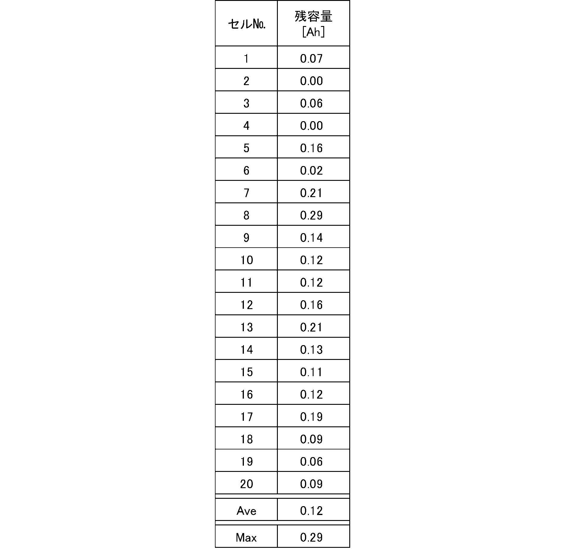
セルバランスの補正方式には「パッシブ方式」と「アクティブ方式」がある。パッシブ方式では放電対象となったセルを抵抗を介して放電させてセルバランス補正をするため、回路システムはシンプルだが、余剰な放電容量を強制的に放電する。アクティブ方式は、あるセルの余剰な放電容量を、他の電池セルに移すことで均等化する。しかし、システムが複雑になるためコストが上昇するし、容量を100%、他の電池セルに移せるわけではない。本技術では、いずれの方式のセルバランス補正を使用することができる。本技術では、低温の場合はセルバランスの補正で発生する放電容量を有効活用する。すなわち、放電容量を利用して、温まりにくくかつ冷めやすいセルをヒーターで温める。
「第3の実施形態のシステム構成」
第3の実施形態は、例えば上述した第1の実施形態に対して図13に示すように、セルバランス補正回路200を付加した構成である。セルバランス補正回路200には、通常のセルバランス補正回路とヒーター用セルバランス補正回路が含まれている。このようにセルバランス補正回路を二つ備えるのは、環境温度が高いような場合でもヒーターが動作して電池モジュール11aが劣化することを防止するためである。なお、第3の実施形態は、第2の実施形態と組み合わせるようにしてもよい。
第3の実施形態は、例えば上述した第1の実施形態に対して図13に示すように、セルバランス補正回路200を付加した構成である。セルバランス補正回路200には、通常のセルバランス補正回路とヒーター用セルバランス補正回路が含まれている。このようにセルバランス補正回路を二つ備えるのは、環境温度が高いような場合でもヒーターが動作して電池モジュール11aが劣化することを防止するためである。なお、第3の実施形態は、第2の実施形態と組み合わせるようにしてもよい。
なお、システムを理解しやすいように、電池モジュール11aが3段の電池ブロックBL1,BL2及びBL3が直列接続された構成を有するものとしている。さらに、上段の電池ブロックBL1が温まりにくいものであり、中段の電池ブロックBL2のみが放電容量が多くセルバランスをする必要があるとの2条件を仮定して説明する。したがって、ヒーター(ヒーター抵抗R11,R12,R13)は、電池ブロックBL1に対して設けられている。
図14に示すように、通常のセルバランス補正回路201の抵抗R1,R2,R3及びFETQ1,Q2,Q3の直列回路と、ヒーター用セルバランス補正回路202のヒーター抵抗R11,R12,R13及びFETQ11,Q12,Q13の直列回路が各電池ブロックに対して並列に接続されている。
中段の電池ブロックBL2が放電容量が多い場合、点線の電流経路211で示すように、FETQ2がONとされ、抵抗R2を通じて電池ブロックBL2が放電される。又は電流経路212で示すように、FETQ12がONとされ、ヒーター抵抗R12を通じて電池ブロックBL2が放電される。ヒーター抵抗R12に電流が流れることによって、ヒーター抵抗R2が発熱し、電池ブロックBL2が温められる。
各電池ブロックの温度がサーミスタ、熱電対などの温度センサ1301 ,1302 ,1303 によって検出され、MPU140に検出結果が供給される。MPU140は、6個のFETQ1~Q13のON/OFFを別々に制御することができる。また、MPU140は、各電池ブロックBL1,BL2,BL3のそれぞれの電圧値が入力される。MPU140は、図12のフローチャートを参照して説明した第3の実施形態の処理を行うように各素子を制御する。
第3の実施形態の通常のセルバランス処理について説明する。まず、各電池ブロックの温度が充電可能温度(0℃)より高いかどうかを確認する。そして、各電池ブロックの電圧、容量を確認したのちに、通常のセルバランス補正を制御しているFETQ2をONにして点線211の放電ルートで容量を消費してセルバランスを調整する。
低温時には、各電池ブロックの温度が充電禁止温度以下で放電可能温度であるかを確認する。充電禁止温度以下で放電可能温度である場合、各セルの電圧、容量を確認したのちに、低温時でのセルバランスを制御しているFETQ12をONにして点線212の放電ルートで容量を消費してセルバランスを調整し、かつヒーター抵抗R12の発熱によって温まりにくい電池ブロックBL2を温める。
上述した第3の実施形態によれば、セルバランスの補正で無駄になるセルの容量を利用して、温まりにくく、かつ冷めやすいセルを先に温めるので、充電禁止温度から充電可能温度に到達するまでの時間を短縮できる。また、セルバランスの補正で使用する放電容量の有効活用できる。さらに、伝熱部材を使用することなく、ヒーターで温めるため著しい重量増加がなく、簡単な構成とできる。さらに、回路システムがシンプルなパッシブ方式のセルバランス補正回路の場合には、少し構成を変更すればよいので、アクティブ方式より回路システムを簡単とできる。
<4.応用例>
次に、本技術の応用例について説明する。
「応用例としての車両における蓄電システム」
本技術を車両用の蓄電システムに適用した例について、図15を参照して説明する。図15に、本技術が適用されるシリーズハイブリッドシステムを採用するハイブリッド車両の構成の一例を概略的に示す。シリーズハイブリッドシステムはエンジンで動かす発電機で発電された電力、あるいはそれをバッテリーに一旦貯めておいた電力を用いて、電力駆動力変換装置で走行する車である。
次に、本技術の応用例について説明する。
「応用例としての車両における蓄電システム」
本技術を車両用の蓄電システムに適用した例について、図15を参照して説明する。図15に、本技術が適用されるシリーズハイブリッドシステムを採用するハイブリッド車両の構成の一例を概略的に示す。シリーズハイブリッドシステムはエンジンで動かす発電機で発電された電力、あるいはそれをバッテリーに一旦貯めておいた電力を用いて、電力駆動力変換装置で走行する車である。
このハイブリッド車両7200には、エンジン7201、発電機7202、電力駆動力変換装置7203、駆動輪7204a、駆動輪7204b、車輪7205a、車輪7205b、バッテリー7208、車両制御装置7209、各種センサ7210、充電口7211が搭載されている。バッテリー7208に対して、上述した本技術の蓄電装置が適用される。
ハイブリッド車両7200は、電力駆動力変換装置7203を動力源として走行する。電力駆動力変換装置7203の一例は、モーターである。バッテリー7208の電力によって電力駆動力変換装置7203が作動し、この電力駆動力変換装置7203の回転力が駆動輪7204a、7204bに伝達される。なお、必要な個所に直流-交流(DC-AC)あるいは逆変換(AC-DC変換)を用いることによって、電力駆動力変換装置7203が交流モーターでも直流モーターでも適用可能である。各種センサ7210は、車両制御装置7209を介してエンジン回転数を制御したり、図示しないスロットルバルブの開度(スロットル開度)を制御したりする。各種センサ7210には、速度センサ、加速度センサ、エンジン回転数センサなどが含まれる。
エンジン7201の回転力は発電機7202に伝えられ、その回転力によって発電機7202により生成された電力をバッテリー7208に蓄積することが可能である。
図示しない制動機構によりハイブリッド車両が減速すると、その減速時の抵抗力が電力駆動力変換装置7203に回転力として加わり、この回転力によって電力駆動力変換装置7203により生成された回生電力がバッテリー7208に蓄積される。
バッテリー7208は、ハイブリッド車両の外部の電源に接続されることで、その外部電源から充電口211を入力口として電力供給を受け、受けた電力を蓄積することも可能である。
図示しないが、二次電池に関する情報に基づいて車両制御に関する情報処理を行なう情報処理装置を備えていても良い。このような情報処理装置としては、例えば、電池の残量に関する情報に基づき、電池残量表示を行う情報処理装置などがある。
なお、以上は、エンジンで動かす発電機で発電された電力、或いはそれをバッテリーに一旦貯めておいた電力を用いて、モーターで走行するシリーズハイブリッド車を例として説明した。しかしながら、エンジンとモーターの出力がいずれも駆動源とし、エンジンのみで走行、モーターのみで走行、エンジンとモーター走行という3つの方式を適宜切り替えて使用するパラレルハイブリッド車に対しても本技術は有効に適用可能である。さらに、エンジンを用いず駆動モータのみによる駆動で走行する所謂、電動車両に対しても本技術は有効に適用可能である。
以上、本技術に係る技術が適用され得るハイブリッド車両7200の一例について説明した。本技術に係る技術は、以上説明した構成のうち、例えば、車両制御装置7209およびバッテリー7208に好適に適用され得る。具体的には、電池モジュール11aをバッテリー7208に適用し、ECU11bおよび表示部11cの機能を車両制御装置7209の一機能として適用する。
「応用例としての住宅における蓄電システム」
本技術を住宅用の蓄電システムに適用した例について、図16を参照して説明する。例えば住宅9001用の蓄電システム9100においては、火力発電9002a、原子力発電9002b、水力発電9002c等の集中型電力系統9002から電力網9009、情報網9012、スマートメータ9007、パワーハブ9008等を介し、電力が蓄電装置9003に供給される。これと共に、家庭内発電装置9004等の独立電源から電力が蓄電装置9003に供給される。蓄電装置9003に供給された電力が蓄電される。蓄電装置9003を使用して、住宅9001で使用する電力が給電される。住宅9001に限らずビルに関しても同様の蓄電システムを使用できる。
本技術を住宅用の蓄電システムに適用した例について、図16を参照して説明する。例えば住宅9001用の蓄電システム9100においては、火力発電9002a、原子力発電9002b、水力発電9002c等の集中型電力系統9002から電力網9009、情報網9012、スマートメータ9007、パワーハブ9008等を介し、電力が蓄電装置9003に供給される。これと共に、家庭内発電装置9004等の独立電源から電力が蓄電装置9003に供給される。蓄電装置9003に供給された電力が蓄電される。蓄電装置9003を使用して、住宅9001で使用する電力が給電される。住宅9001に限らずビルに関しても同様の蓄電システムを使用できる。
住宅9001には、発電装置9004、電力消費装置9005、蓄電装置9003、各装置を制御する制御装置9010、スマートメータ9007、各種情報を取得するセンサ9011が設けられている。各装置は、電力網9009および情報網9012によって接続されている。発電装置9004として、太陽電池、燃料電池等が利用され、発電した電力が電力消費装置9005および/または蓄電装置9003に供給される。電力消費装置9005は、冷蔵庫9005a、空調装置9005b、テレビジョン受信機9005c、風呂9005d等である。さらに、電力消費装置9005には、電動車両9006が含まれる。電動車両9006は、電気自動車9006a、ハイブリッドカー9006b、電気バイク9006cである。
蓄電装置9003に対して、上述した本技術のバッテリユニットが適用される。蓄電装置9003は、二次電池又はキャパシタから構成されている。例えば、リチウムイオン電池によって構成されている。リチウムイオン電池は、定置型であっても、電動車両9006で使用されるものでも良い。スマートメータ9007は、商用電力の使用量を測定し、測定された使用量を、電力会社に送信する機能を備えている。電力網9009は、直流給電、交流給電、非接触給電の何れか一つまたは複数を組み合わせても良い。
各種のセンサ9011は、例えば人感センサ、照度センサ、物体検知センサ、消費電力センサ、振動センサ、接触センサ、温度センサ、赤外線センサ等である。各種センサ9011により取得された情報は、制御装置9010に送信される。センサ9011からの情報によって、気象の状態、人の状態等が把握されて電力消費装置9005を自動的に制御してエネルギー消費を最小とすることができる。さらに、制御装置9010は、住宅9001に関する情報をインターネットを介して外部の電力会社等に送信することができる。
パワーハブ9008によって、電力線の分岐、直流交流変換等の処理がなされる。制御装置9010と接続される情報網9012の通信方式としては、UART(Universal Asynchronous Receiver-Transmitter:非同期シリアル通信用送受信回路)等の通信インターフェースを使う方法、Bluetooth(登録商標)、ZigBee、Wi-Fi等の無線通信規格によるセンサネットワークを利用する方法がある。Bluetooth(登録商標)方式は、マルチメディア通信に適用され、一対多接続の通信を行うことができる。ZigBeeは、IEEE(Institute of Electrical and Electronics Engineers) 802.15.4の物理層を使用するものである。IEEE802.15.4は、PAN(Personal Area Network) またはW(Wireless)PANと呼ばれる短距離無線ネットワーク規格の名称である。
制御装置9010は、外部のサーバ9013と接続されている。このサーバ9013は、住宅9001、電力会社、サービスプロバイダーの何れかによって管理されていても良い。サーバ9013が送受信する情報は、たとえば、消費電力情報、生活パターン情報、電力料金、天気情報、天災情報、電力取引に関する情報である。これらの情報は、家庭内の電力消費装置(たとえばテレビジョン受信機)から送受信しても良いが、家庭外の装置(たとえば、携帯電話機等)から送受信しても良い。これらの情報は、表示機能を持つ機器、たとえば、テレビジョン受信機、携帯電話機、PDA(Personal Digital Assistants)等に、表示されても良い。
各部を制御する制御装置9010は、CPU(Central Processing Unit )、RAM(Random Access Memory)、ROM(Read Only Memory)等で構成され、この例では、蓄電装置9003に格納されている。制御装置9010は、蓄電装置9003、家庭内発電装置9004、電力消費装置9005、各種センサ9011、サーバ9013と情報網9012により接続され、例えば、商用電力の使用量と、発電量とを調整する機能を有している。なお、その他にも、電力市場で電力取引を行う機能等を備えていても良い。
以上のように、電力が火力9002a、原子力9002b、水力9002c等の集中型電力系統9002のみならず、家庭内発電装置9004(太陽光発電、風力発電)の発電電力を蓄電装置9003に蓄えることができる。したがって、家庭内発電装置9004の発電電力が変動しても、外部に送出する電力量を一定にしたり、または、必要なだけ放電するといった制御を行うことができる。例えば、太陽光発電で得られた電力を蓄電装置9003に蓄えると共に、夜間は料金が安い深夜電力を蓄電装置9003に蓄え、昼間の料金が高い時間帯に蓄電装置9003によって蓄電した電力を放電して利用するといった使い方もできる。
なお、この例では、制御装置9010が蓄電装置9003内に格納される例を説明したが、スマートメータ9007内に格納されても良いし、単独で構成されていても良い。さらに、蓄電システム9100は、集合住宅における複数の家庭を対象として用いられてもよいし、複数の戸建て住宅を対象として用いられてもよい。
以上、本技術に係る技術が適用され得る蓄電システム9100の一例について説明した。本技術に係る技術は、以上説明した構成のうち、蓄電装置9003に好適に適用され得る。具体的には、電池装置11を蓄電装置9003に適用することができる。
「その他の応用例」
本技術は、航空機にも適用可能である。航空機は、高度の上空を飛行するため、電池モジュールの使用環境温度が0℃以下になり得る。このような場合でも上述した可変電流放電制御を行うことにより対応することができる。また、本技術は、大型の電動車両や航空機に限らず、電動バイク、電動自転車、電動三輪車、電動小型飛行体(ドローン等とも称される)等にも応用可能である。
本技術は、航空機にも適用可能である。航空機は、高度の上空を飛行するため、電池モジュールの使用環境温度が0℃以下になり得る。このような場合でも上述した可変電流放電制御を行うことにより対応することができる。また、本技術は、大型の電動車両や航空機に限らず、電動バイク、電動自転車、電動三輪車、電動小型飛行体(ドローン等とも称される)等にも応用可能である。
また、本技術は、二次電池が使用され得る電子機器(PC、スマートフォン、携帯電話、電動工具、おもちゃ等)にも応用可能であり、上述した電池装置から電力の供給を受ける電子機器として本技術を実現することも可能である。
<5.変形例>
表示部に代えて、または表示部とともに、音声等により可変電流放電制御が行われていることをユーザに対して報知してもよい。また、可変電流放電制御が行われたことが他の機器に対して通信により通知されてもよい。
表示部に代えて、または表示部とともに、音声等により可変電流放電制御が行われていることをユーザに対して報知してもよい。また、可変電流放電制御が行われたことが他の機器に対して通信により通知されてもよい。
図3のフローチャートを参照して説明した処理が適宜、変更されてもよい。例えば、ステップS14の判断が、放電電流値を切り替えたタイミングだけでなく、放電中に周期的に行われてもよい。また、放電電流値の切替のタイミングで電池モジュールの電圧が放電終止電圧を下回る場合には、放電電流値を小さくしたり、切替前の放電電流値に戻す処理が追加されてもよい。図3のフローチャートで説明した処理の全てが可変電流放電制御に対応する処理である必要はない。
可変電流放電制御における放電電流値の切替は、ステップ状に限らず、例えば放電電流値をリニアに増加させる制御でもよい。
以上、本技術の実施形態について具体的に説明したが、上述の各実施形態に限定されるものではなく、本技術の技術的思想に基づく各種の変形が可能である。例えば、上述の実施形態において挙げた構成、方法、工程、形状、材料および数値などはあくまでも例に過ぎず、必要に応じてこれと異なる構成、方法、工程、形状、材料および数値などを用いてもよい。
なお、本技術は、以下のような構成も取ることができる。
(1)
電池の温度を検知する温度検知部と、充電開始直前に前記温度検知部が一定温度範囲を検知した場合に、二次電池に対する可変電流放電を行う制御部とを備える電池装置。
(2)
前記一定温度範囲は、-20℃~0℃である(1)に記載の電池装置。
(3)
複数の電池セルが直列及び/又は並列に接続されると共に、互いに接近して組み立てられた組電池と、
前記組電池の電池セルのそれぞれに接続されたバランス補正用のスイッチ素子と、
前記スイッチ素子に流れる電流が供給される複数の加熱素子と、
前記複数の加熱素子を前記組電池の温まりにくい電池セルに接触又は近傍に配置し、
前記温度検知部が一定温度範囲を検知した場合に、バランス補正を行った後に、前記組電池を放電させることによって、充電可能な温度とするようにした(1)または(2)に記載の電池装置。
(4)
複数の二次電池が直列及び/又は並列に接続されると共に、互いに接近して組み立てられた組電池と、
前記組電池の前記二次電池のそれぞれに接続されたバランス補正用のスイッチ素子及び前記スイッチ素子に流れる電流が供給される複数の抵抗を有する第1のバランス補正回路と、
前記組電池の前記二次電池のそれぞれに接続されたバランス補正用のスイッチ素子及び前記スイッチ素子に流れる電流が供給される複数のヒーター抵抗を有する第2のバランス補正回路と、
前記複数のヒーター抵抗が前記組電池の温まりにくい二次電池に接触又はその近傍に配置され、
充電可能な温度において、前記第1のバランス補正回路によってバランス補正を行い、
放電可能であり且つ充電可能でない温度において、前記第2のバランス補正回路によってバランス補正を行った後に、前記二次電池に対する可変電流放電制御を行うようにした(1)から(3)までのいずれか電池装置。
(5)
前記可変電流放電制御は、前記二次電池の温度に応じて、異なる放電電流値で当該二次電池を放電させる制御である
(1)から(4)までのいずれかに記載の電池装置。
(6)
前記可変電流放電制御は、前記二次電池の温度の上昇に伴って、放電電流値を大きくして当該二次電池を放電させる制御である
(5)に記載の電池装置。
(7)
前記制御部は、前記二次電池の電圧が放電終止電圧を下回る場合には、前記可変電流放電制御を停止するように構成される
(1)から(6)までのいずれかに記載の電池装置。
(8)
前記制御部は、前記二次電池のSOC(State Of Charge)に応じて、前記可変電流放電制御を行うか否かを判断するように構成される
(1)から(7)までのいずれかに記載の電池装置。
(9)
前記可変電流放電制御が行われることに応じて前記二次電池から出力される電力を貯蔵する電力貯蔵部を備える
(1)から(8)までのいずれかに記載の電池装置。
(10)
前記二次電池の負荷としてヒーターが接続される
(1)から(9)までのいずれかに記載の電池装置。
(11)
(1)に記載の電池装置から電力の供給を受ける
電子機器。
(12)
(1)に記載の電池装置を備える
電動車両。
(13)
(1)に記載の電池装置を備える
蓄電システム。
(14)
制御部が、
放電可能であり且つ充電可能でない温度において、二次電池の温度の上昇に伴って、放電電流値を大きくして当該二次電池を放電させる可変電流放電制御を行う
制御方法。
(1)
電池の温度を検知する温度検知部と、充電開始直前に前記温度検知部が一定温度範囲を検知した場合に、二次電池に対する可変電流放電を行う制御部とを備える電池装置。
(2)
前記一定温度範囲は、-20℃~0℃である(1)に記載の電池装置。
(3)
複数の電池セルが直列及び/又は並列に接続されると共に、互いに接近して組み立てられた組電池と、
前記組電池の電池セルのそれぞれに接続されたバランス補正用のスイッチ素子と、
前記スイッチ素子に流れる電流が供給される複数の加熱素子と、
前記複数の加熱素子を前記組電池の温まりにくい電池セルに接触又は近傍に配置し、
前記温度検知部が一定温度範囲を検知した場合に、バランス補正を行った後に、前記組電池を放電させることによって、充電可能な温度とするようにした(1)または(2)に記載の電池装置。
(4)
複数の二次電池が直列及び/又は並列に接続されると共に、互いに接近して組み立てられた組電池と、
前記組電池の前記二次電池のそれぞれに接続されたバランス補正用のスイッチ素子及び前記スイッチ素子に流れる電流が供給される複数の抵抗を有する第1のバランス補正回路と、
前記組電池の前記二次電池のそれぞれに接続されたバランス補正用のスイッチ素子及び前記スイッチ素子に流れる電流が供給される複数のヒーター抵抗を有する第2のバランス補正回路と、
前記複数のヒーター抵抗が前記組電池の温まりにくい二次電池に接触又はその近傍に配置され、
充電可能な温度において、前記第1のバランス補正回路によってバランス補正を行い、
放電可能であり且つ充電可能でない温度において、前記第2のバランス補正回路によってバランス補正を行った後に、前記二次電池に対する可変電流放電制御を行うようにした(1)から(3)までのいずれか電池装置。
(5)
前記可変電流放電制御は、前記二次電池の温度に応じて、異なる放電電流値で当該二次電池を放電させる制御である
(1)から(4)までのいずれかに記載の電池装置。
(6)
前記可変電流放電制御は、前記二次電池の温度の上昇に伴って、放電電流値を大きくして当該二次電池を放電させる制御である
(5)に記載の電池装置。
(7)
前記制御部は、前記二次電池の電圧が放電終止電圧を下回る場合には、前記可変電流放電制御を停止するように構成される
(1)から(6)までのいずれかに記載の電池装置。
(8)
前記制御部は、前記二次電池のSOC(State Of Charge)に応じて、前記可変電流放電制御を行うか否かを判断するように構成される
(1)から(7)までのいずれかに記載の電池装置。
(9)
前記可変電流放電制御が行われることに応じて前記二次電池から出力される電力を貯蔵する電力貯蔵部を備える
(1)から(8)までのいずれかに記載の電池装置。
(10)
前記二次電池の負荷としてヒーターが接続される
(1)から(9)までのいずれかに記載の電池装置。
(11)
(1)に記載の電池装置から電力の供給を受ける
電子機器。
(12)
(1)に記載の電池装置を備える
電動車両。
(13)
(1)に記載の電池装置を備える
蓄電システム。
(14)
制御部が、
放電可能であり且つ充電可能でない温度において、二次電池の温度の上昇に伴って、放電電流値を大きくして当該二次電池を放電させる可変電流放電制御を行う
制御方法。
11・・・電池装置
11a・・・電池モジュール
11b・・・ECU
11c・・・表示部
12・・・車内ヒーター
130・・・温度センサ
140・・・MPU
11a・・・電池モジュール
11b・・・ECU
11c・・・表示部
12・・・車内ヒーター
130・・・温度センサ
140・・・MPU
Claims (14)
- 電池の温度を検知する温度検知部と、充電開始直前に前記温度検知部が一定温度範囲を検知した場合に、二次電池に対する可変電流放電を行う制御部とを備える電池装置。
- 前記一定温度範囲は、-20℃~0℃である請求項1に記載の電池装置。
- 複数の電池セルが直列及び/又は並列に接続されると共に、互いに接近して組み立てられた組電池と、
前記組電池の電池セルのそれぞれに接続されたバランス補正用のスイッチ素子と、
前記スイッチ素子に流れる電流が供給される複数の加熱素子と、
前記複数の加熱素子を前記組電池の温まりにくい電池セルに接触又は近傍に配置し、
前記温度検知部が一定温度範囲を検知した場合に、バランス補正を行った後に、前記組電池を放電させることによって、充電可能な温度とするようにした請求項1に記載の電池装置。 - 複数の二次電池が直列及び/又は並列に接続されると共に、互いに接近して組み立てられた組電池と、
前記組電池の前記二次電池のそれぞれに接続されたバランス補正用のスイッチ素子及び前記スイッチ素子に流れる電流が供給される複数の抵抗を有する第1のバランス補正回路と、
前記組電池の前記二次電池のそれぞれに接続されたバランス補正用のスイッチ素子及び前記スイッチ素子に流れる電流が供給される複数のヒーター抵抗を有する第2のバランス補正回路と、
前記複数のヒーター抵抗が前記組電池の温まりにくい二次電池に接触又はその近傍に配置され、
充電可能な温度において、前記第1のバランス補正回路によってバランス補正を行い、
放電可能であり且つ充電可能でない温度において、前記第2のバランス補正回路によってバランス補正を行った後に、前記二次電池に対する可変電流放電制御を行うようにした請求項1に記載の電池装置。 - 前記可変電流放電制御は、前記二次電池の温度に応じて、異なる放電電流値で当該二次電池を放電させる制御である
請求項4に記載の電池装置。 - 前記可変電流放電制御は、前記二次電池の温度の上昇に伴って、放電電流値を大きくして当該二次電池を放電させる制御である
請求項5に記載の電池装置。 - 前記制御部は、前記二次電池の電圧が放電終止電圧を下回る場合には、前記可変電流放電制御を停止するように構成される
請求項1に記載の電池装置。 - 前記制御部は、前記二次電池のSOC(State Of Charge)に応じて、前記可変電流放電制御を行うか否かを判断するように構成される
請求項1に記載の電池装置。 - 前記可変電流放電制御が行われることに応じて前記二次電池から出力される電力を貯蔵する電力貯蔵部を備える
請求項1に記載の電池装置。 - 前記二次電池の負荷としてヒーターが接続される
請求項1に記載の電池装置。 - 請求項1に記載の電池装置から電力の供給を受ける
電子機器。 - 請求項1に記載の電池装置を備える
電動車両。 - 請求項1に記載の電池装置を備える
蓄電システム。 - 制御部が、
放電可能であり且つ充電可能でない温度において、二次電池の温度の上昇に伴って、放電電流値を大きくして当該二次電池を放電させる可変電流放電制御を行う
制御方法。
Priority Applications (2)
| Application Number | Priority Date | Filing Date | Title |
|---|---|---|---|
| CN201780031452.8A CN109155531B (zh) | 2016-07-22 | 2017-06-13 | 电池装置、电子设备、电动车辆、蓄电系统以及控制方法 |
| US16/178,026 US10833375B2 (en) | 2016-07-22 | 2018-11-01 | Battery device, electronic device, electronic vehicle, power storage system, and control method |
Applications Claiming Priority (4)
| Application Number | Priority Date | Filing Date | Title |
|---|---|---|---|
| JP2016144157 | 2016-07-22 | ||
| JP2016-144157 | 2016-07-22 | ||
| JP2017-082188 | 2017-04-18 | ||
| JP2017082188A JP6665826B2 (ja) | 2016-07-22 | 2017-04-18 | 電池装置 |
Related Child Applications (1)
| Application Number | Title | Priority Date | Filing Date |
|---|---|---|---|
| US16/178,026 Continuation US10833375B2 (en) | 2016-07-22 | 2018-11-01 | Battery device, electronic device, electronic vehicle, power storage system, and control method |
Publications (1)
| Publication Number | Publication Date |
|---|---|
| WO2018016231A1 true WO2018016231A1 (ja) | 2018-01-25 |
Family
ID=60992096
Family Applications (1)
| Application Number | Title | Priority Date | Filing Date |
|---|---|---|---|
| PCT/JP2017/021751 Ceased WO2018016231A1 (ja) | 2016-07-22 | 2017-06-13 | 電池装置、電子機器、電動車両、蓄電システムおよび制御方法 |
Country Status (2)
| Country | Link |
|---|---|
| CN (1) | CN109155531B (ja) |
| WO (1) | WO2018016231A1 (ja) |
Cited By (1)
| Publication number | Priority date | Publication date | Assignee | Title |
|---|---|---|---|---|
| CN112172509A (zh) * | 2019-07-03 | 2021-01-05 | 现代自动车株式会社 | 四轮驱动车辆 |
Families Citing this family (5)
| Publication number | Priority date | Publication date | Assignee | Title |
|---|---|---|---|---|
| JP2020137287A (ja) * | 2019-02-21 | 2020-08-31 | エイブリック株式会社 | 充放電制御回路、充放電制御装置及びバッテリ装置 |
| KR102676247B1 (ko) * | 2020-01-09 | 2024-06-20 | 현대자동차주식회사 | 연료 전지를 포함하는 차량, 이 차량에서 수행되는 배터리 충전 방법, 및 이 방법을 실행하기 위한 프로그램을 기록한 기록 매체 |
| US11588194B2 (en) * | 2020-08-24 | 2023-02-21 | Guangzhou Automobile Group Co., Ltd. | Battery heat adjustment circuit and method, storage medium and electronic device |
| CN112331961B (zh) * | 2020-10-30 | 2021-12-14 | 湖北亿纬动力有限公司 | 一种电芯的温度控制方法、装置、设备及存储介质 |
| CN116278977A (zh) * | 2023-02-09 | 2023-06-23 | 奇瑞新能源汽车股份有限公司 | 电池加热系统、电池加热方法、设备及存储介质 |
Citations (5)
| Publication number | Priority date | Publication date | Assignee | Title |
|---|---|---|---|---|
| JP2009054419A (ja) * | 2007-08-27 | 2009-03-12 | Canon Inc | バッテリー機器及びその制御方法、並びにプログラム |
| JP2013200966A (ja) * | 2012-03-23 | 2013-10-03 | Jm Energy Corp | 蓄電セル温度調整回路及び当該蓄電セル温度調整回路を備えた蓄電装置 |
| JP2014157778A (ja) * | 2013-02-18 | 2014-08-28 | Kayaba Ind Co Ltd | 充放電システム |
| JP2015029366A (ja) * | 2013-07-30 | 2015-02-12 | 日本電気株式会社 | 電源装置および電源の昇温方法 |
| JP2015047027A (ja) * | 2013-08-29 | 2015-03-12 | 三菱自動車工業株式会社 | 電動車両の充電システム |
Family Cites Families (6)
| Publication number | Priority date | Publication date | Assignee | Title |
|---|---|---|---|---|
| EP1661707A1 (en) * | 2003-09-03 | 2006-05-31 | Sony Corporation | Liquid ejector and liquid ejecting method |
| JP5285323B2 (ja) * | 2008-04-22 | 2013-09-11 | 株式会社日本自動車部品総合研究所 | 車両用二次電池の充電制御装置 |
| JP2010246225A (ja) * | 2009-04-03 | 2010-10-28 | Sony Corp | 電池パックおよび充電方法 |
| JP2013096752A (ja) * | 2011-10-28 | 2013-05-20 | Sanyo Electric Co Ltd | パック電池の異常判定方法及びパック電池 |
| US20140253046A1 (en) * | 2013-03-11 | 2014-09-11 | Enerdel, Inc. | Method and apparatus for battery control |
| ES2975858T3 (es) * | 2014-10-13 | 2024-07-16 | 24M Tech Inc | Sistemas y métodos de carga y de formación de baterías en serie |
-
2017
- 2017-06-13 CN CN201780031452.8A patent/CN109155531B/zh active Active
- 2017-06-13 WO PCT/JP2017/021751 patent/WO2018016231A1/ja not_active Ceased
Patent Citations (5)
| Publication number | Priority date | Publication date | Assignee | Title |
|---|---|---|---|---|
| JP2009054419A (ja) * | 2007-08-27 | 2009-03-12 | Canon Inc | バッテリー機器及びその制御方法、並びにプログラム |
| JP2013200966A (ja) * | 2012-03-23 | 2013-10-03 | Jm Energy Corp | 蓄電セル温度調整回路及び当該蓄電セル温度調整回路を備えた蓄電装置 |
| JP2014157778A (ja) * | 2013-02-18 | 2014-08-28 | Kayaba Ind Co Ltd | 充放電システム |
| JP2015029366A (ja) * | 2013-07-30 | 2015-02-12 | 日本電気株式会社 | 電源装置および電源の昇温方法 |
| JP2015047027A (ja) * | 2013-08-29 | 2015-03-12 | 三菱自動車工業株式会社 | 電動車両の充電システム |
Cited By (2)
| Publication number | Priority date | Publication date | Assignee | Title |
|---|---|---|---|---|
| CN112172509A (zh) * | 2019-07-03 | 2021-01-05 | 现代自动车株式会社 | 四轮驱动车辆 |
| CN112172509B (zh) * | 2019-07-03 | 2024-04-05 | 现代自动车株式会社 | 四轮驱动车辆 |
Also Published As
| Publication number | Publication date |
|---|---|
| CN109155531B (zh) | 2022-04-29 |
| CN109155531A (zh) | 2019-01-04 |
Similar Documents
| Publication | Publication Date | Title |
|---|---|---|
| JP6665826B2 (ja) | 電池装置 | |
| CN109155531B (zh) | 电池装置、电子设备、电动车辆、蓄电系统以及控制方法 | |
| US8658299B2 (en) | Battery pack thermal management system and method | |
| JP7778894B2 (ja) | 二次電池モジュール | |
| CN103094636B (zh) | 放电控制方法、电池组、蓄电系统、电子设备及电动车辆 | |
| EP2796312B1 (en) | Electrical storage device, electronic instrument, power system, and electric vehicle | |
| EP3018791B1 (en) | Power storage device and power storage device control method | |
| US9276417B2 (en) | Battery control system, battery pack, electronic device and charger | |
| US10056773B2 (en) | Battery control device, control method, control system and electric vehicle | |
| US9525289B2 (en) | Battery control system and battery pack | |
| JP5929526B2 (ja) | 電源供給装置および電源切り換え方法 | |
| JP6347212B2 (ja) | 制御装置、蓄電モジュール、電動車両、電源システムおよび制御方法 | |
| WO2015151432A1 (en) | Charging device, charging control method, electricity storage device, power storage device, power system, and electric vehicle | |
| Rahman et al. | Wireless battery management system of electric transport | |
| JP2012227986A (ja) | 電池パック、電力システムおよび電動車両 | |
| JP6787476B2 (ja) | バッテリ装置、バッテリ管理装置、電子機器、電動車両、蓄電装置及び電力システム | |
| JP2013011536A (ja) | 電池モニタ回路、蓄電装置、電子機器、電動車両および電力システム | |
| CN104919676A (zh) | 蓄电装置及启动方法 | |
| JP6459277B2 (ja) | 直並列電池パックおよび直並列電池パックの制御方法 | |
| KR20240107388A (ko) | 하이브리드 밸런싱하는 배터리 관리 시스템 및 및 이를 포함하는 배터리 팩 및 전기 차량 | |
| Hamm | Conceptual Design of a Battery Pack for Use in a Mobile Hybridized Power Generation System |
Legal Events
| Date | Code | Title | Description |
|---|---|---|---|
| 121 | Ep: the epo has been informed by wipo that ep was designated in this application |
Ref document number: 17830751 Country of ref document: EP Kind code of ref document: A1 |
|
| NENP | Non-entry into the national phase |
Ref country code: DE |
|
| 122 | Ep: pct application non-entry in european phase |
Ref document number: 17830751 Country of ref document: EP Kind code of ref document: A1 |