WO2018008767A1 - Battery exterior material and battery - Google Patents
Battery exterior material and battery Download PDFInfo
- Publication number
- WO2018008767A1 WO2018008767A1 PCT/JP2017/025078 JP2017025078W WO2018008767A1 WO 2018008767 A1 WO2018008767 A1 WO 2018008767A1 JP 2017025078 W JP2017025078 W JP 2017025078W WO 2018008767 A1 WO2018008767 A1 WO 2018008767A1
- Authority
- WO
- WIPO (PCT)
- Prior art keywords
- layer
- battery
- heat
- surface protective
- protective layer
- Prior art date
Links
Images

Classifications
-
- H—ELECTRICITY
- H01—ELECTRIC ELEMENTS
- H01G—CAPACITORS; CAPACITORS, RECTIFIERS, DETECTORS, SWITCHING DEVICES OR LIGHT-SENSITIVE DEVICES, OF THE ELECTROLYTIC TYPE
- H01G11/00—Hybrid capacitors, i.e. capacitors having different positive and negative electrodes; Electric double-layer [EDL] capacitors; Processes for the manufacture thereof or of parts thereof
- H01G11/78—Cases; Housings; Encapsulations; Mountings
-
- H—ELECTRICITY
- H01—ELECTRIC ELEMENTS
- H01M—PROCESSES OR MEANS, e.g. BATTERIES, FOR THE DIRECT CONVERSION OF CHEMICAL ENERGY INTO ELECTRICAL ENERGY
- H01M10/00—Secondary cells; Manufacture thereof
- H01M10/04—Construction or manufacture in general
-
- H—ELECTRICITY
- H01—ELECTRIC ELEMENTS
- H01M—PROCESSES OR MEANS, e.g. BATTERIES, FOR THE DIRECT CONVERSION OF CHEMICAL ENERGY INTO ELECTRICAL ENERGY
- H01M50/00—Constructional details or processes of manufacture of the non-active parts of electrochemical cells other than fuel cells, e.g. hybrid cells
- H01M50/10—Primary casings, jackets or wrappings of a single cell or a single battery
- H01M50/102—Primary casings, jackets or wrappings of a single cell or a single battery characterised by their shape or physical structure
- H01M50/105—Pouches or flexible bags
-
- Y—GENERAL TAGGING OF NEW TECHNOLOGICAL DEVELOPMENTS; GENERAL TAGGING OF CROSS-SECTIONAL TECHNOLOGIES SPANNING OVER SEVERAL SECTIONS OF THE IPC; TECHNICAL SUBJECTS COVERED BY FORMER USPC CROSS-REFERENCE ART COLLECTIONS [XRACs] AND DIGESTS
- Y02—TECHNOLOGIES OR APPLICATIONS FOR MITIGATION OR ADAPTATION AGAINST CLIMATE CHANGE
- Y02E—REDUCTION OF GREENHOUSE GAS [GHG] EMISSIONS, RELATED TO ENERGY GENERATION, TRANSMISSION OR DISTRIBUTION
- Y02E60/00—Enabling technologies; Technologies with a potential or indirect contribution to GHG emissions mitigation
- Y02E60/10—Energy storage using batteries
-
- Y—GENERAL TAGGING OF NEW TECHNOLOGICAL DEVELOPMENTS; GENERAL TAGGING OF CROSS-SECTIONAL TECHNOLOGIES SPANNING OVER SEVERAL SECTIONS OF THE IPC; TECHNICAL SUBJECTS COVERED BY FORMER USPC CROSS-REFERENCE ART COLLECTIONS [XRACs] AND DIGESTS
- Y02—TECHNOLOGIES OR APPLICATIONS FOR MITIGATION OR ADAPTATION AGAINST CLIMATE CHANGE
- Y02P—CLIMATE CHANGE MITIGATION TECHNOLOGIES IN THE PRODUCTION OR PROCESSING OF GOODS
- Y02P70/00—Climate change mitigation technologies in the production process for final industrial or consumer products
- Y02P70/50—Manufacturing or production processes characterised by the final manufactured product
Definitions
- the present invention relates to a battery exterior material and a battery.
- a battery exterior material a laminate material obtained by laminating a metal container (metal can container) formed by drawing metal into a cylindrical shape or a rectangular tube shape, and a resin layer and a metal foil layer (mainly aluminum foil).
- a battery using a laminate is suitable for weight reduction and volume density improvement.
- a battery exterior material having a surface resin layer with an irregular shape on the surface by adding a filler to the outer surface of the base material layer was developed for the purpose of imparting a matte feeling and improving moldability.
- Such a conventional battery exterior material is heat sealed to form a package that accommodates the battery element.
- the surface glossiness of the surface resin layer of the heat seal portion depends on the heat and pressure during heat sealing. It sometimes rose.
- the conventional battery exterior material has a gloss difference between the heat seal portion and the non-heat seal portion in the vicinity of the battery exterior material after the battery element is accommodated, and the appearance is impaired, resulting in a defective product. This problem was not taken into account at all.
- the present invention has been made in view of the above-described situation, and an object of the present invention is to provide a battery exterior material that can reduce defects due to the appearance mismatch of the battery exterior material after housing the battery, and a battery using the battery exterior material. It is what.
- the present invention is a battery exterior material comprising a surface protective layer, a base material layer, an adhesive layer, a barrier layer and a heat-fusible resin layer in order from the outside, wherein the heat-fusible resin layers are opposed to each other.
- the surface gloss of the surface protective layer according to JIS Z 8741 (1997) of the heat protective part of the surface protective layer when heat sealed under conditions of 190 ° C. and 1.0 MPa for 6 seconds
- This is a battery exterior material having a difference from the specular glossiness of less than 1.8 in accordance with JIS Z 8741 (1997) of the non-heat seal portion.
- the surface protective layer has irregularities on the surface opposite to the substrate layer side, and when the arithmetic average roughness of the irregularities is Ra, Ra is the following formula: It is preferable to satisfy. 0.20 ⁇ m ⁇ Ra ⁇ 0.50 ⁇ m
- the surface protective layer preferably contains a filler, and the filler includes titanium oxide, silica, talc, clay, heavy calcium carbonate, light calcium carbonate, barium sulfate, calcium silicate, synthetic silicate, It is preferable that the inorganic filler is made of at least one selected from the group consisting of aluminum hydroxide and silicate fine powder.
- a battery in which the difference between the specular gloss according to JIS Z 8741 (1997) and the specular gloss according to JIS Z 8741 (1997) of the non-heat-sealed portion of the package is less than 1.8
- the present inventions will be described in detail.
- the numerical range indicated by “to” means “above” or “below”, except where the numerical ranges are clearly stated as “above” or “below”.
- 2 to 15 mm means 2 mm or more and 15 mm or less.
- the present inventors have focused on the amount of change in the glossiness of the surface protective layer of the battery exterior material by heat sealing.
- the amount of change in glossiness between the heat sealing portion and the non-heat sealing portion is controlled within a predetermined range.
- the battery exterior material of the present invention has the above-described configuration, it is possible to reduce defects due to appearance mismatch in the heat sealing process during battery manufacture. For this reason, the battery exterior material of this invention can be used conveniently for the battery container excellent in the external appearance.
- the battery packaging material 10 of the present invention includes a surface protective layer 11, a base material layer 12, an adhesive layer 13, a barrier layer 14, and a heat-fusible resin layer 15 in order from the outside. ing.
- FIG. 1 is a figure which shows an example of the cross-sectional structure of the battery exterior material of this invention.
- the surface protective layer 11 is the outermost layer
- the heat-fusible resin layer 15 is the innermost layer. That is, at the time of assembling the battery, the battery element is sealed by heat-sealing the heat-fusible resin layers 15 located on the periphery of the battery element to seal the battery element. That is, the “outer side” is the side opposite to the side on which the battery element is sealed when the battery is configured using the battery packaging material of the present invention.
- the battery exterior material of the present invention has a change in glossiness of the surface protective layer when heat sealed under the conditions of 190 ° C., 1.0 MPa, 6 seconds with the heat-fusible resin layers facing each other. That is, the difference between the mirror glossiness according to JIS Z 8741 (1997) of the heat seal portion and the mirror glossiness according to JIS Z 8741 (1997) of the non-heat seal portion of the surface protective layer is It is less than 1.8. If the difference in specular gloss is 1.8 or more, the difference in gloss between the heat-sealed portion and the non-heat-sealed portion becomes large, causing a defect due to appearance mismatch.
- the difference in specular gloss after the heat sealing is preferably 1.0 or less.
- the heat sealing was performed using a heat sealer TP-701-B manufactured by Tester Sangyo Co., Ltd. under the conditions of 190 ° C., 1.0 MPa, and 6 seconds.
- the specular gloss is obtained by using a 60-degree specular gloss method in accordance with JIS Z 8741 (1997).
- the gloss measuring instrument Micro-Tri-Gloss manufactured by Toyo Seiki Seisakusho Co., Ltd. Can be measured.
- the “non-heat-sealed portion” means a portion other than the portion where heat-sealing is performed in the surface protective layer, and the “non-heat-sealed portion” means the surface of the battery exterior material before being heat-sealed.
- the amount of change in the specular gloss of the surface protective layer after such heat sealing is compared with the conventional specular gloss on the surface protective layer side in the battery outer packaging material of the present invention described above. It can be preferably satisfied by setting a larger value. Further, the amount of change in the specular gloss is controlled by heating the resin contained in the surface protective layer, controlling the softness when pressed to prevent the filler from sinking, and heating the filler. It is possible to prevent the filler from being crushed by controlling the softness when pressed.
- heat sealing is performed from the surface protective layer side with the heat-fusible resin layers facing each other.
- the surface protective layer has a role of imparting a matte feeling to the battery outer packaging material of the present invention, and the specular gloss of such a surface protective layer is 3.0. It is preferable that it is 11.0 or less.
- the specular gloss on the surface protective layer side is less than 3.0, there is a difference in gloss between the heat-sealed portion and the other (hereinafter also referred to as non-heat-sealed portion) during heat sealing of the battery outer packaging material of the present invention. It may become large and cause defects due to appearance mismatch.
- the matte feeling on the surface protective layer side exceeds 11.0, the matte feeling may be insufficient and the glossiness of the battery outer packaging material of the present invention may be increased.
- the more preferable lower limit of the specular gloss on the surface protective layer side is 3.5, the more preferable upper limit is 8.0, the still more preferable lower limit is 3.6, the still more preferable upper limit is 6.5, and the particularly preferable upper limit is 5.
- the specular glossiness of the said surface protective layer is a specular glossiness in a non-heat-sealed part when heat-sealing to the battery exterior material of this invention on the conditions mentioned above.
- the battery exterior material provided with the conventional matte feeling is given a matte feeling mainly from the viewpoint of moldability, and the above-mentioned specular gloss is often about 2.0. Compared to the material, the matte feeling was less glossy and stronger.
- the difference in specular gloss between the heat seal portion and the non-heat seal portion is preferably 1.0 or less, more preferably 0.8 or less, and even more preferably 0.5 or less. If the difference in specular gloss between the heat seal part and the non-heat seal part exceeds 1.0, the difference in gloss between the heat seal part and the non-heat seal part becomes large, and it is determined that the appearance is poor. There is.
- the surface protective layer has irregularities on the surface opposite to the base material layer side, and when the arithmetic average roughness of the irregularities on the surface of the surface protective layer is Ra, the Ra satisfies the following formula: Is preferred. 0.20 ⁇ m ⁇ Ra ⁇ 0.50 ⁇ m If the Ra is less than 0.20 ⁇ m, the specular gloss of the surface protective layer may increase and a desired matte feeling may not be obtained. If the Ra exceeds 0.50 ⁇ m, the surface protective layer after heat sealing The amount of change in specular gloss may be large.
- the more preferable lower limit of Ra is 0.24 ⁇ m
- the more preferable upper limit is 0.42 ⁇ m
- the still more preferable lower limit is 0.30 ⁇ m
- the more preferable upper limit is 0.37 ⁇ m.
- the arithmetic average roughness Ra of the surface protective layer is a value obtained by photographing the surface of the surface protective layer and using the image processing software VK Analyzer of Keyence Co., Ltd. from the photographed image.
- the surface protective layer preferably contains a filler.
- a filler By containing the filler, an uneven shape can be formed on the surface of the surface protective layer, and a matte feeling can be imparted to the battery outer packaging material of the present invention.
- means for forming irregularities on the surface of the surface protective layer include, for example, means for shaping with an embossed plate having an irregular shape, means for containing a filler in the composition constituting the surface protective layer, and the like. However, for reasons such as production cost, a means for containing a filler in the composition constituting the surface protective layer is preferable.
- the filler is not particularly limited, but from titanium oxide, silica, talc, clay, heavy calcium carbonate, light calcium carbonate, barium sulfate, calcium silicate, synthetic silicate, aluminum hydroxide, and fine powder of silicate.
- the inorganic filler is made of at least one selected from the group consisting of: Examples of the organic filler include fillers made of high melting point nylon, crosslinked acrylic, crosslinked styrene, crosslinked polyethylene, benzoguanamine and the like. Although it does not specifically limit as a shape of the said organic filler, For example, spherical shape, fibrous shape, plate shape, an indeterminate form, and balloon shape are mentioned.
- an inorganic filler made of silica or precipitated barium sulfate is preferable because it is easy to handle and easily available.
- the precipitated barium sulfate refers to barium sulfate produced using a chemical reaction, and is characterized in that the particle size can be controlled.
- the filler As content of the said filler, it adjusts suitably in the range with which the requirements of the specular glossiness by the surface protective layer side in the battery exterior material of this invention mentioned above are satisfy
- the filler is silica having an average particle size of 1.0 ⁇ m or more and 3.0 ⁇ m or less, it is preferably 2.0% by mass or more and 8.7% by mass or less in the surface protective layer.
- the filler When the filler is precipitated barium sulfate having an average particle size of less than 1.0 ⁇ m, it is preferably 13.0% by mass or more and 40.0% by mass or less in the surface protective layer.
- the said filler content is content of the filler in the said surface protective layer, and is content after the solvent volatilizes from the resin composition mentioned later for forming this surface protective layer.
- the surface protective layer preferably contains the filler in the resin component.
- the resin component preferably includes a thermosetting resin, and any thermosetting resin may be used as long as it causes polymerization upon heating to form a polymer network structure and cure.
- thermosetting resin include epoxy resins, amino resins (melamine resins, benzoguanamine resins, etc.), acrylic resins, urethane resins, phenol resins, unsaturated polyester resins, alkyd resins, and the like.
- thermosetting resins urethane resins and epoxy resins are preferable from the viewpoints of shortening the curing time, improving moldability and chemical resistance, and more preferably two-component curable urethane resins and 2 A liquid curable epoxy resin is mentioned, Especially preferably, a 2 liquid curable epoxy resin is mentioned.
- the two-component curable urethane resin include a combination of a polyol compound (main agent) and an isocyanate compound (curing agent), and the two-component curable epoxy resin specifically includes an epoxy resin ( And a combination of an acid anhydride, an amine compound, or an amino resin (curing agent).
- the polyfunctional urethane (meth) acrylate which consists of a combination of the polyfunctional (meth) acrylate (main ingredient) which has active hydrogen, and polyisocyanate (curing agent) is also preferable.
- the polyol compound used as the main agent is not particularly limited, and examples thereof include polyester polyol, polyester polyurethane polyol, polyether polyol, and polyether polyurethane polyol. These polyol compounds may be used individually by 1 type, and may be used in combination of 2 or more type.
- the isocyanate compound used as a curing agent is not particularly limited.
- specific examples of the polyisocyanate include diphenylmethane diisocyanate (MDI), polyphenylmethane diisocyanate (polymeric MDI), toluene diisocyanate (TDI), hexamethylene diisocyanate (HDI), and bis (4-isocyanatocyclohexyl) methane (H12MDI).
- MDI diphenylmethane diisocyanate
- polymeric MDI polyphenylmethane diisocyanate
- TDI toluene diisocyanate
- HDI hexamethylene diisocyanate
- H12MDI bis (4-isocyanatocyclohexyl) methane
- Aromatic diisocyanates such as isophorone diisocyanate (IPDI), 1,5-naphthalene diisocyanate (1,5-NDI), 3,3′-dimethyl-4,4′-diphenylene diisocyanate (TODI), xylene diisocyanate (XDI) Aliphatic diisocyanates such as tramethylene diisocyanate, hexamethylene diisocyanate, trimethylhexamethylene diisocyanate, isophorone diisocyanate DOO; 4,4'-methylenebis (cyclohexyl isocyanate), alicyclic diisocyanates such as isophorone diisocyanate; 1,5-naphthalene diisocyanate (1, 5-NDI) polycyclic aromatic diisocyanates such as are exemplified. Specific examples of the adduct include those obtained by adding trimethylolpropane, glycol and the like to the polyisocyanate. These isocyanate compounds may be
- thermosetting resins may be crosslinkable elastomers.
- a crosslinkable elastomer is a thermosetting resin that can impart a soft segment to a cured product.
- the above-described main agent only needs to have a structure capable of imparting a soft segment.
- the crosslinkable elastomer is used as a part of a thermosetting resin used for forming a layer constituting the surface protective layer in order to provide the layer constituting the surface protective layer with a desired hardness. Can do.
- thermosetting resins may be used individually by 1 type, and may be used in combination of 2 or more type.
- the surface protective layer may be formed of a plurality of layers.
- the thermosetting resin used in each layer may be the same or different, and the type of thermosetting resin is a function to be provided in each layer. It may be appropriately selected according to the physical properties and the like.
- the layer that forms the outermost layer (the outermost layer located on the side opposite to the base layer) has a polycyclic aroma from the viewpoint of having excellent chemical resistance.
- a thermosetting resin having a group skeleton and / or a heterocyclic skeleton is preferably used.
- thermosetting resin having a polycyclic aromatic skeleton examples include an epoxy resin having a polycyclic aromatic skeleton and a urethane resin having a polycyclic aromatic skeleton.
- thermosetting resin having the heterocyclic skeleton examples include amino resins such as melamine resin and benzoguanamine resin. These thermosetting resins having a polycyclic aromatic skeleton and / or a heterocyclic skeleton may be either a one-component curable type or a two-component curable type.
- the epoxy resin having a polycyclic aromatic skeleton includes a reaction product of dihydroxynaphthalene and epihalohydrin; a condensate of naphthol and aldehydes (naphthol novolak resin) and a reaction product of epihalohydrin; Condensate of dihydroxynaphthalene and aldehyde and reaction product of epihalohydrin; condensate of mono- or dihydroxynaphthalene and xylylene glycol and reaction product of epihalohydrin; adduct of mono- or dihydroxynaphthalene and diene compound And a reaction product of epihalohydrin; a reaction product of polynaphthols in which naphthols are directly coupled to epihalohydrin, and the like.
- examples of the urethane resin having a polycyclic aromatic skeleton include a reaction product of a polyol compound and an isocyanate compound having a polycyclic aromatic skeleton.
- the resin composition forming the surface protective layer may further contain a curing accelerator in addition to the filler and the resin component described above.
- a curing accelerator By coexisting a curing accelerator together with the thermosetting resin, the surface protective layer can be cured in a short time without requiring aging under high temperature conditions during production to form a layer having the specific hardness. it can.
- the “curing accelerator” is a substance that does not form a crosslinked structure by itself, but promotes the crosslinking reaction of the thermosetting resin, and has the effect of promoting the crosslinking reaction of the thermosetting resin. Is also a substance that may form a crosslinked structure.
- the type of the curing accelerator is appropriately selected according to the thermosetting resin to be used so that the above-described hardness can be satisfied.
- an amidine compound, a carbodiimide compound, a ketimine compound, a hydrazine compound, a sulfonium salt examples thereof include benzothiazolium salts and tertiary amine compounds.
- amidine compound is not particularly limited.
- imidazole compound 1,8-diazabicyclo [5.4.0] undec-7ene (DBU), 1,5-diazabicyclo [4.3.0] none-5 -Ene (DBN), guanidine compounds and the like.
- imidazole compound examples include 2-methylimidazole, 2-ethylimidazole, 2-undecylimidazole, 2,4-dimethylimidazole, 2-heptadecylimidazole, 1,2-dimethylimidazole, 1,2 -Diethylimidazole, 2-ethyl-4-methylimidazole, 2-phenylimidazole, 1-benzyl-2-phenylimidazole, 1-cyanoethyl-2-methylimidazole, 1-cyanoethyl-2-undecylimidazole, 1-benzyl- 2-methylimidazole, 2,4-diamino-6- [2′-methylimidazolyl- (1) ′]-ethyl-S-triazine, 2,4-diamino-6- [2′-ethyl-4′-methyl Imidazolyl- (1) ′]-ethyl-S-triazine, 2,4-didi
- the carbodiimide compound is not particularly limited.
- Specific examples of the ketone include methyl ethyl ketone, methyl isopropyl ketone, methyl tertiary butyl ketone, methyl cyclohexyl ketone, diethyl ketone, ethyl propyl ketone, ethyl butyl ketone, dipropyl ketone, dibutyl ketone, and diisobutyl ketone. It is done.
- amine examples include aromatic polyamines such as o-phenylenediamine, m-phenylenediamine, p-phenylenediamine, m-xylylenediamine, diaminodiphenylmethane, diaminodiphenylsulfone, and diaminodiethyldiphenylmethane.
- aromatic polyamines such as o-phenylenediamine, m-phenylenediamine, p-phenylenediamine, m-xylylenediamine, diaminodiphenylmethane, diaminodiphenylsulfone, and diaminodiethyldiphenylmethane.
- Polyether skeleton diamines such as isophorone diamine, 1,3-bisaminomethylcyclohexane, 1-cyclohexylamino-3-aminopropane, 3-aminomethyl-3,3,5-trimethylcyclohexylamine: norbornane Skeletal diamine; Polyamidoamine having an amino group at the molecular end of polyamide; 2,5-dimethyl-2,5-hexamethylenediamine, mensendiamine, 1,4-bis (2-amino-2-methylpropyl) piperazine Etc. are mentioned as specific examples. These ketimine compounds may be used individually by 1 type, and may be used in combination of 2 or more type.
- the hydrazine compound is not particularly limited, and examples thereof include dipic acid dihydrazide and isophthalic acid dihydrazide. These hydrazine compounds may be used individually by 1 type, and may be used in combination of 2 or more type.
- the sulfonium salt is not particularly limited.
- 4-acetophenyldimethylsulfonium hexafluoroantimonate 4-acetophenyldimethylsulfonium hexafluoroarsenate, dimethyl-4- (benzyloxycarbonyloxy) phenylsulfonium hexafluoroantimonate
- Alkylsulfonium salts such as dimethyl-4- (benzoyloxy) phenylsulfonium hexafluoroantimonate and dimethyl-4- (benzoyloxy) phenylsulfonium hexafluoroarsenate
- benzyl-4-hydroxyphenylmethylsulfonium hexafluoroantimonate 4 -Acetoxyphenylbenzylmethylsulfonium hexafluoroantimonate
- benzyl-4-methoxyphenyl Benzylsulfonium salts such
- the benzothiazolium salt is not particularly limited.
- a benzothiazolium salt is mentioned.
- These benzothiazolium salts may be used individually by 1 type, and may be used in combination of 2 or more type.
- the tertiary amine compound is not particularly limited, and examples thereof include trimethylamine, triethylamine, tripropylamine, tributylamine, triethylenediamine, 1,4-diazabicyclo [2.2.2] octane, quinuclidine, and 3-quinuclidinol.
- the thermal acid generator is a substance that generates an acid by heating and functions as a curing accelerator.
- Specific examples of the curing accelerator that can function as a thermal acid generator include a sulfonium salt and a benzothiazolium salt.
- the curing accelerator is a thermal latent that is activated under a predetermined heating condition (for example, 80 to 200 ° C., preferably 100 to 160 ° C.) to promote the crosslinking reaction of the thermosetting resin.
- a predetermined heating condition for example, 80 to 200 ° C., preferably 100 to 160 ° C.
- the heat-latent substance among the above-described curing accelerators include epoxy adducts in which an epoxy compound is added to an amidine compound, a hydrazine compound, a tertiary amine compound, or the like.
- the curing accelerator does not function as a curing agent in a sealed state, that is, a moisture blocking state, but the sealed state is opened and hydrolyzed under the presence of moisture as a curing agent.
- a sealed state that is, a moisture blocking state
- the hydrolytic latent substance include an epoxy adduct obtained by adding an epoxy compound to an amidine compound, a hydrazine compound, a tertiary amine compound, or the like.
- hardening accelerators may be used individually by 1 type, and may be used in combination of 2 or more type.
- an amidine compound and a sulfonium salt are preferable, and an amidine compound is more preferable.
- hardening accelerators may be used individually by 1 type in the said surface protective layer, and may be used in combination of 2 or more type. Further, when the surface protective layer is formed of a plurality of layers, the curing accelerator used in each layer constituting the surface protective layer may be the same or different. May be appropriately selected according to the function and physical properties to be provided in each layer.
- the content of the curing accelerator in the resin composition used for forming the surface protective layer is appropriately set according to the type of thermosetting resin to be used, the type of curing accelerator, and the like.
- the total amount of the curing accelerator is 0.01 to 6 parts by weight, preferably 0.05 to 5 parts by weight, more preferably 0.1 to 2 parts by weight with respect to 100 parts by weight of the thermosetting resin. Part.
- the surface protective layer may contain at least one of a pigment and a dye as necessary.
- a pigment and a dye When the surface protective layer contains at least one of a pigment and a dye, whitening at the time of molding can be more effectively suppressed, and wear resistance can be improved.
- the battery exterior material of the present invention can be given distinctiveness (colored by at least one of the pigment and the dye), and the battery exterior material of the present invention. It is possible to impart a matte design to the surface of the battery or to further improve the heat dissipation by increasing the thermal conductivity of the battery exterior material of the present invention.
- the material of the pigment is not particularly limited and may be either an inorganic pigment or an organic pigment.
- the inorganic pigment include carbon black, carbon nanotube, graphite, kaolin, magnesium hydroxide, zinc oxide, magnesium oxide, aluminum oxide, neodymium oxide, antimony oxide, cerium oxide, calcium sulfate, lithium carbonate, and gold.
- Specific examples of the organic pigment include azo pigments, polycyclic pigments, lake pigments, and fluorescent pigments. These pigments may be used alone or in combination of two or more.
- the shape of the pigment is not particularly limited, and examples thereof include a spherical shape, a fiber shape, a plate shape, an indeterminate shape, and a balloon shape.
- the average particle size of the pigment is not particularly limited, but for example, it is preferably 0.01 to 3 ⁇ m, more preferably 0.05 to 1 ⁇ m.
- the average particle size of the pigment is measured by using a Shimadzu laser diffraction particle size distribution analyzer SALD-2100-WJA1, and using compressed air, the powder to be measured is jetted from a nozzle and dispersed in the air. It is a value measured by an injection type dry measurement method.
- the pigment may be subjected to various surface treatments such as an insulation treatment and a high dispersibility treatment (resin coating treatment) on the surface as necessary.
- the type of the dye is not particularly limited as long as it can be dissolved and dispersed in the resin composition used for forming the surface protective layer.
- a nitro dye, an azo dye, a stilbene dye, a carbonium dye Quinoline dyes, methine dyes, thiazole dyes, quinimine dyes, anthraquinone dyes, indigoid dyes, phthalocyanine dyes, and the like preferably azo dyes, carbonium dyes, anthraquinone dyes, and the like. These dyes may be used alone or in combination of two or more.
- pigments and dyes from the viewpoint of further improving the heat dissipation of the battery packaging material of the present invention, it is preferably a pigment, more preferably an inorganic pigment, more preferably carbon such as carbon black, carbon nanotube, and graphite. Materials, particularly preferably carbon black.
- the pigment and / or dye may be any one of these two or more layers in order to contain the pigment and the like. It may be contained in one layer, or may be contained in two or more layers. From the viewpoint of reducing the difference in color tone between the molded part and the non-molded part after molding the battery exterior material of the present invention, the surface protective layer has a multilayer structure composed of two or more layers. It is preferable to contain a pigment and / or dye in two or more layers, and the surface protective layer is made into a three-layer structure composed of three layers, and the pigment and / or dye is contained in all three layers. Further preferred.
- the content should be given to the type of pigment and / or dye to be used and the battery packaging material of the present invention. What is necessary is just to set suitably according to discriminability, heat dissipation, etc.
- a pigment and / or dye are 1-30 in total amount. A mass part is mentioned. From the viewpoint of imparting even better discrimination, the total amount of the pigment and / or dye is 3 to 20 parts by mass with respect to 100 parts by mass of the resin component contained in the layer containing the pigment and / or dye. .
- the total amount of the pigment and / or dye is 5 to 15 parts by mass.
- the resin composition used for the formation of the surface protective layer has an organic filler, a slip agent, and a solvent, depending on the functionality to be provided in the surface protective layer.
- Other additives such as elastomer resins may be included.
- the surface protective layer contains an organic filler or a slip agent, it gives a slip effect to the surface of the battery outer packaging material of the present invention, improves the formability / workability in press molding or embossing, Can be improved.
- organic filler For example, high melting point nylon, crosslinked acrylic, crosslinked styrene, crosslinked polyethylene, benzoguanamine etc. are mentioned.
- the shape of the organic filler is not particularly limited, and examples thereof include a spherical shape, a fiber shape, a plate shape, an indeterminate shape, and a balloon shape.
- a non-reactive slip agent may be sufficient and a reactive slip agent may be sufficient.
- the reactive slip agent is less likely to lose bleed from the outermost surface layer constituting the surface protective layer, and suppresses the occurrence of powder blowing and set-off during use and the reduction of the slip effect over time.
- a reactive slip agent is preferable because of the advantage that it can be used.
- the said non-reactive slip agent is a compound which does not have the functional group which reacts with the resin component mentioned above, and couple
- the reactive slip agent is a compound that has a functional group that reacts with the resin component and chemically binds, and can impart slip properties (slip properties).
- non-reactive slip agent examples include fatty acid amide, metal soap, hydrophilic silicone, silicone grafted acrylic, silicone grafted epoxy, silicone grafted polyether, and silicone grafted polyester. , Block type silicone acrylic copolymer, polyglycerol-modified silicone, paraffin and the like. These non-reactive slip agents may be used individually by 1 type, and may be used in combination of 2 or more type.
- the type of functional group is appropriately set according to the type of resin component used, for example, hydroxyl group, mercapto group, hydrolyzable silyl group, isocyanate group, epoxy group, Examples thereof include a polymerizable vinyl group and a (meth) acryloyl group.
- the number of functional groups per molecule is not particularly limited, and examples thereof include 1 to 3, preferably 1 or 2.
- the reactive slip agent include modified silicones having the above functional groups; modified fluororesins having the above functional groups; fatty acid amides such as stearic acid amide, oleic acid amide, erucic acid amide, and ethylenebisstearic acid amide. And compounds having the functional group introduced therein; metal soaps having the functional group introduced therein; and paraffins having the functional group introduced therein.
- These reactive slip agents may be used individually by 1 type, and may be used in combination of 2 or more type.
- the modified silicone having the functional group, the modified fluororesin having the functional group, and the silicone-modified resin having the functional group are preferable.
- modified silicone examples include, for example, a modified silicone obtained by block polymerization of a polymer having the above functional group, such as a modified silicone obtained by block polymerization of an acrylic resin; and a modified silicone obtained by graft polymerization of an acrylate. And modified silicone obtained by graft polymerization of a monomer having the above functional group.
- modified fluororesin specifically, for example, a modified fluororesin in which a monomer having the above functional group is graft polymerized, such as a fluororesin in which an acrylate is graft polymerized; an acrylic resin is block polymerized
- a fluororesin obtained by block polymerization of a polymer having the above functional group such as a modified fluororesin.
- silicone-modified resin specifically, the silicone having the functional group and the graft polymerized, such as a silicone-modified acrylic resin in which the silicone is graft-polymerized to the acrylic resin having the functional group. Examples include silicone-modified resins.
- examples thereof include a modified fluororesin that is polymerized at one end of the resin.
- modified silicone and modified fluororesin for example, “Modiper (registered trademark) F / FS series” (manufactured by NOF Corporation), “Symac (registered trademark) series” (manufactured by Toagosei Co., Ltd.) and the like are commercially available. These commercial products can also be used.
- the content is not particularly limited, but for example, for 100 parts by mass of the resin component,
- the total amount of slip agent is 1 to 12 parts by mass, preferably 3 to 10 parts by mass, more preferably 5 to 8 parts by mass.
- the surface of the surface protective layer of the battery outer packaging material of the present invention preferably has a Martens hardness of 15 N / mm 2 or more measured by a load of 1 mN by an indentation method.
- the surface protective layer since the surface protective layer has such a specific hardness, whitening at the time of forming a package for housing the battery element is effectively suppressed, and the battery is excellent. It has moldability. Also, whitening in view of more effectively suppressing the time of molding, As the hardness, more preferably 18N / mm 2 or more, further preferably 20 N / mm 2 or more.
- the upper limit of the Martens hardness is about 25 N / mm 2 .
- the said surface protective layer has the said Martens hardness, the collapsing of a filler is suppressed effectively and the objective of this invention can be achieved suitably.
- a specific method for measuring the Martens hardness of the surface of the surface protective layer is a diamond regular quadrangular pyramid having a diagonal angle of 136 ° from the direction perpendicular to the surface of the surface protective layer (surface opposite to the base material layer).
- a Vickers indenter having a shape is pushed in, the Martens hardness is calculated from the obtained load-displacement curve, and the average obtained at five locations is the Martens hardness of the surface of the surface protective layer. More specifically, the Martens hardness is calculated by calculating the surface area A (mm 2 ) of a pyramidal depression formed by indentation at the maximum indentation depth h of the Vickers indenter, and dividing the test load F (N) (F / A).
- the Martens hardness of the surface protective layer can be measured by pressing an indenter into the surface of the surface protective layer under the following specific conditions.
- the Martens hardness can be measured by an indentation method using a Picodenter HM-500 manufactured by Fischer Instruments.
- the hardness of the surface protective layer can be set to the above-described value by appropriately adjusting the type and amount of the thermosetting resin used for forming the surface protective layer.
- the desired hardness can be set by appropriately adjusting the amount and type of the crosslinkable elastomer in the thermosetting resin used for forming the surface protective layer.
- the thickness of the surface protective layer is, for example, about 0.5 to 10 ⁇ m, preferably about 1 to 9 ⁇ m.
- the base material layer is a layer provided inside the surface protective layer.
- the material for forming the base material layer is not particularly limited as long as it has insulating properties.
- the material for forming the base material layer include resin films such as polyester resin, polyamide resin, epoxy resin, acrylic resin, fluorine resin, polyurethane resin, silicon resin, phenol resin, and a mixture or copolymer thereof.
- resin films such as polyester resin, polyamide resin, epoxy resin, acrylic resin, fluorine resin, polyurethane resin, silicon resin, phenol resin, and a mixture or copolymer thereof.
- a polyester resin and a polyamide resin are mentioned, More preferably, a biaxially stretched polyester resin and a biaxially stretched polyamide resin are mentioned.
- polyester resin examples include polyethylene terephthalate, polybutylene terephthalate, polyethylene naphthalate, polybutylene naphthalate, copolyester, and polycarbonate.
- polyamide resin examples include nylon 6, nylon 6,6, a copolymer of nylon 6 and nylon 6,6, nylon 6,10, polymetaxylylene adipamide (MXD6), and the like. Can be mentioned.
- the said base material layer may be formed from the resin film of one layer, in order to improve pinhole resistance and insulation, it may be formed with the resin film of two or more layers.
- the base material layer is formed of a multilayer resin film, two or more resin films may be laminated through an adhesive layer such as an adhesive or an adhesive resin, and the adhesive component used The type and amount are the same as in the case of the adhesive layer described later.
- stacking two or more resin films A well-known method is employable, For example, a dry lamination method, a sandwich lamination method, etc. are mentioned, Preferably the dry lamination method is mentioned.
- the dry lamination method is mentioned.
- the thickness of the adhesive layer is, for example, about 2 to 5 ⁇ m.
- the thickness of the base material layer is not particularly limited as long as it functions as a base material layer. Examples thereof include about 1 to 50 ⁇ m, preferably about 3 to 25 ⁇ m, and more preferably about 3 to 15 ⁇ m.
- the adhesive layer is a layer provided between the base material layer and the barrier layer as necessary in order to firmly bond the base material layer and the barrier layer.
- the adhesive layer is formed of an adhesive that can bond the base material layer and the barrier layer.
- the adhesive used for forming the adhesive layer may be a two-component curable adhesive or a one-component curable adhesive.
- the bonding mechanism of the adhesive used for forming the adhesive layer is not particularly limited, and any of a chemical reaction type, a solvent volatilization type, a heat melting type, a hot pressure type, and the like may be used.
- polyester resins such as polyethylene terephthalate, polybutylene terephthalate, polyethylene naphthalate, polybutylene naphthalate, polyethylene isophthalate, polycarbonate, and copolyester
- Polyether adhesive such as polyethylene terephthalate, polybutylene terephthalate, polyethylene naphthalate, polybutylene naphthalate, polyethylene isophthalate, polycarbon
- Polyolefin resins polyvinyl acetate resins, cellulose adhesives, (meth) acrylic resins, polyimide resins, urea resins, melamine resins and other amino resins, chloroprene rubber, nitrile rubber, - Len rubbers such as butadiene rubber, silicone-based resins.
- These adhesive components may be used individually by 1 type, and may be used in combination of 2 or more type.
- a polyurethane adhesive is preferable.
- the adhesive layer may contain a color pigment such as carbon black or titanium oxide in a range that does not hinder the adhesive performance of the adhesive component.
- the thickness of the adhesive layer is not particularly limited as long as it functions as an adhesive layer.
- the thickness is about 1 to 10 ⁇ m, preferably about 2 to 5 ⁇ m.
- the barrier layer is a layer that functions as a barrier layer for preventing the penetration of water vapor, oxygen, light, etc. into the battery, in addition to improving the strength of the battery packaging material.
- the barrier layer is preferably made of a metal, and specific examples of the metal include aluminum, stainless steel, and titanium, and preferably aluminum.
- the barrier layer can be formed of, for example, a metal foil, a metal vapor-deposited film, an inorganic oxide vapor-deposited film, a film provided with these vapor-deposited films, or the like, preferably formed of a metal foil, and formed of an aluminum foil. More preferably.
- annealed aluminum JIS H4160: 1994 A8021H-O, JIS H4160: 1994 A8079H.
- -O, JIS H4000: 2014 A8021P-O, and JIS H4000: 2014 A8079P-O are more preferable.
- the thickness of the barrier layer is not particularly limited as long as it functions as a barrier layer, and can be, for example, about 10 to 50 ⁇ m, preferably about 20 to 40 ⁇ m.
- the barrier layer is preferably subjected to chemical conversion treatment on at least one surface, preferably both surfaces, for the purpose of stabilizing adhesion, preventing dissolution and corrosion, and the like.
- the chemical conversion treatment refers to a treatment for forming an acid-resistant film on the surface of the barrier layer.
- chromic acid compounds such as chromium nitrate, chromium fluoride, chromium sulfate, chromium acetate, chromium oxalate, chromium biphosphate, chromic acetyl acetate, chromium chloride, potassium sulfate chromium, etc.
- X represents a hydrogen atom, a hydroxyl group, an alkyl group, a hydroxyalkyl group, an allyl group or a benzyl group.
- R 1 and R 2 are the same or different and each represents a hydroxyl group, an alkyl group or a hydroxyalkyl group.
- examples of the alkyl group represented by X, R 1 and R 2 include a methyl group, an ethyl group, an n-propyl group, an isopropyl group, an n-butyl group, an isobutyl group, Examples thereof include a linear or branched alkyl group having 1 to 4 carbon atoms such as a tert-butyl group.
- Examples of the hydroxyalkyl group represented by X, R 1 and R 2 include a hydroxymethyl group, a 1-hydroxyethyl group, a 2-hydroxyethyl group, a 1-hydroxypropyl group, a 2-hydroxypropyl group, 3- C1-C4 straight or branched chain in which one hydroxy group such as hydroxypropyl group, 1-hydroxybutyl group, 2-hydroxybutyl group, 3-hydroxybutyl group, 4-hydroxybutyl group is substituted
- An alkyl group is mentioned.
- the alkyl group and hydroxyalkyl group represented by X, R 1 and R 2 may be the same or different.
- X is preferably a hydrogen atom, a hydroxyl group or a hydroxyalkyl group.
- the number average molecular weight of the aminated phenol polymer having a repeating unit represented by the general formulas (1) to (4) is preferably, for example, 500 to 1,000,000, and preferably about 1,000 to 20,000. More preferred.
- a coating in which metal oxide such as aluminum oxide, titanium oxide, cerium oxide, tin oxide or barium sulfate fine particles are dispersed in phosphoric acid A method of forming a corrosion-resistant layer on the surface of the barrier layer by performing a baking treatment at 150 ° C. or higher can be mentioned. Further, a resin layer obtained by crosslinking a cationic polymer with a crosslinking agent may be further formed on the corrosion-resistant treatment layer.
- examples of the cationic polymer include polyethyleneimine, an ionic polymer complex composed of a polymer having polyethyleneimine and a carboxylic acid, a primary amine graft acrylic resin obtained by graft polymerization of a primary amine on an acrylic main skeleton, and polyallylamine. Or the derivative, aminophenol, etc. are mentioned.
- these cationic polymers only one type may be used, or two or more types may be used in combination.
- examples of the crosslinking agent include a compound having at least one functional group selected from the group consisting of an isocyanate group, a glycidyl group, a carboxyl group, and an oxazoline group, and a silane coupling agent. As these crosslinking agents, only one type may be used, or two or more types may be used in combination.
- the chemical conversion treatment may be performed by only one type of chemical conversion treatment, or may be performed by combining two or more types of chemical conversion treatment. Furthermore, these chemical conversion treatments may be carried out using one kind of compound alone, or may be carried out using a combination of two or more kinds of compounds.
- chromic acid chromate treatment chromate treatment combining a chromic acid compound, a phosphoric acid compound, and an aminated phenol polymer are preferable.
- the amount of the acid-resistant film formed on the surface of the barrier layer is not particularly limited.
- a chromic acid compound per 1 m 2 of the surface of the barrier layer Is preferably about 0.5 to about 50 mg, more preferably about 1.0 to about 40 mg in terms of chromium, and the phosphorus compound is preferably about 0.5 to about 50 mg, more preferably about 1.0 to about 50 mg in terms of phosphorus.
- 40 mg and the aminated phenol polymer is preferably contained in a proportion of about 1 to about 200 mg, more preferably about 5.0 to 150 mg.
- a solution containing a compound used for forming an acid-resistant film is applied to the surface of the barrier layer by a bar coating method, a roll coating method, a gravure coating method, a dipping method, or the like.
- the heating is performed so that the temperature is about 70 ° C. to 200 ° C.
- the barrier layer may be previously subjected to a degreasing treatment by an alkali dipping method, an electrolytic cleaning method, an acid cleaning method, an electrolytic acid cleaning method, or the like. By performing the degreasing treatment in this way, it is possible to more efficiently perform the chemical conversion treatment on the surface of the barrier layer.
- the heat-fusible resin layer corresponds to the innermost layer, and is a layer that heat-welds the heat-fusible resin layers together to seal the battery element when the battery is assembled.
- the resin component used in the heat-fusible resin layer is not particularly limited as long as it can be heat-welded, and examples thereof include polyolefin, cyclic polyolefin, carboxylic acid-modified polyolefin, and carboxylic acid-modified cyclic polyolefin. .
- polystyrene resin examples include polyethylene such as low density polyethylene, medium density polyethylene, high density polyethylene, and linear low density polyethylene; homopolypropylene, polypropylene block copolymer (for example, block copolymer of propylene and ethylene), polypropylene And a random copolymer (eg, a random copolymer of propylene and ethylene); an ethylene-butene-propylene terpolymer; and the like.
- polyethylene and polypropylene are preferable.
- the cyclic polyolefin is a copolymer of an olefin and a cyclic monomer.
- the olefin that is a constituent monomer of the cyclic polyolefin include ethylene, propylene, 4-methyl-1-pentene, styrene, butadiene, and isoprene. Is mentioned.
- examples of the cyclic monomer that is a constituent monomer of the cyclic polyolefin include cyclic alkenes such as norbornene; specifically, cyclic dienes such as cyclopentadiene, dicyclopentadiene, cyclohexadiene, and norbornadiene.
- cyclic alkene is preferable, and norbornene is more preferable.
- the carboxylic acid-modified polyolefin is a polymer modified by block polymerization or graft polymerization of the polyolefin with carboxylic acid.
- Examples of the carboxylic acid used for modification include maleic acid, acrylic acid, itaconic acid, crotonic acid, maleic anhydride, itaconic anhydride and the like.
- the carboxylic acid-modified cyclic polyolefin is obtained by copolymerizing a part of the monomer constituting the cyclic polyolefin in place of the ⁇ , ⁇ -unsaturated carboxylic acid or its anhydride, or by ⁇ , ⁇ with respect to the cyclic polyolefin.
- the cyclic polyolefin to be modified with the carboxylic acid is the same as described above.
- the carboxylic acid used for modification is the same as that used for modification of the polyolefin.
- carboxylic acid-modified polyolefin is preferable; carboxylic acid-modified polypropylene is more preferable.
- the heat-fusible resin layer may be formed of one kind of resin component alone or may be formed of a blend polymer in which two or more kinds of resin components are combined. Furthermore, the heat-fusible resin layer may be formed of only one layer, but may be formed of two or more layers using the same or different resin components.
- the thickness of the heat-fusible resin layer is not particularly limited as long as it functions as the heat-fusible resin layer.
- the thickness is about 10 to 100 ⁇ m, preferably about 15 to 50 ⁇ m.
- an adhesive layer may be provided between the barrier layer and the heat-fusible resin layer as necessary, in order to firmly bond the barrier layer and the heat-fusible resin layer.
- the adhesive layer is formed of an adhesive capable of adhering the barrier layer and the heat-fusible resin layer.
- the adhesive agent used for formation of the said adhesive layer, the adhesion mechanism, the kind of adhesive component, etc. are the same as that of the case of the adhesive layer mentioned above.
- the adhesive component used in the adhesive layer is preferably a polyolefin resin, more preferably a carboxylic acid-modified polyolefin, and particularly preferably a carboxylic acid-modified polypropylene.
- the thickness of the adhesive layer is not particularly limited as long as it exhibits the function as the adhesive layer, and it is, for example, about 2 to 50 ⁇ m, preferably about 15 to 30 ⁇ m.
- the method for producing the battery outer packaging material of the present invention is not particularly limited as long as a laminate in which layers having a predetermined composition are laminated is obtained.
- the following method is exemplified.
- laminate A a laminate in which the base material layer 12, the adhesive layer 13, and the barrier layer 14 shown in FIG. 1 are laminated in order (hereinafter, may be referred to as “laminate A”) is formed.
- the laminate A is formed by, for example, extruding an adhesive used for forming the adhesive layer 13 on the base layer 12 or the barrier layer 14 whose surface is subjected to chemical conversion treatment as necessary.
- the barrier layer 14 or the base material layer 12 may be laminated to dry the adhesive layer 13.
- the heat-fusible resin layer 15 is laminated on the barrier layer 14 of the laminate A.
- the resin component constituting the heat-fusible resin layer 15 is applied to the barrier layer 14 of the laminate A by a gravure coating method or a roll coating method. What is necessary is just to apply
- an adhesive layer (not shown) is provided between the barrier layer 14 and the heat-fusible resin layer 15, for example, (1) the adhesive layer and the heat-sealing layer on the barrier layer 14 of the laminate A (2) Separately, a laminate in which the adhesive layer and the heat-fusible resin layer 15 are laminated is formed, and this is formed into the laminate A.
- a method of laminating on the barrier layer 14 by a thermal laminating method (3) An adhesive for forming an adhesive layer (not shown) on the barrier layer 14 of the laminate A is dried at a high temperature by extrusion or solution coating. Further, a method of laminating by heat laminating method, and laminating the heat-fusible resin layer 15 previously formed into a sheet shape on this adhesive layer by a thermal laminating method, (4) the barrier layer 14 of the laminate A, Heat fusion formed into a sheet Between the resin layer 15, while pouring an adhesive layer is melted, a method of bonding a laminate A and the heat-welding resin layer 15 via an adhesive layer (sandwich lamination method).
- the surface protective layer 11 is laminated on the surface of the base material layer 12 opposite to the barrier layer 14.
- the surface protective layer 11 can be formed, for example, by applying the above-described resin composition for forming the surface protective layer 11 to the surface of the base material layer 12 and curing it by heating.
- the order of the step of laminating the barrier layer 14 on the surface of the base material layer 12 and the step of laminating the surface protective layer 11 on the surface of the base material layer 2 are not particularly limited.
- the barrier layer 14 may be formed on the surface of the base material layer 2 opposite to the surface protective layer 11.
- each layer constituting the laminate improves or stabilizes film forming properties, lamination processing, suitability for final processing of secondary products (pouching, embossing), and the like as necessary. Therefore, surface activation treatment such as corona treatment, blast treatment, oxidation treatment, ozone treatment may be performed.
- the battery packaging material of the present invention is used as a packaging material for sealing and housing battery elements such as a positive electrode, a negative electrode, and an electrolyte.
- a battery element including at least a positive electrode, a negative electrode, and an electrolyte is formed in a state where the metal terminal connected to each of the positive electrode and the negative electrode protrudes to the outside with the battery packaging material of the present invention.
- the heat-fusible resin layer portion of the battery packaging material of the present invention is on the inner side (surface in contact with the battery element).
- a battery in which a battery element including at least a positive electrode, a negative electrode, and an electrolyte is housed in a package including a heat seal portion formed of a battery exterior material, and the JIS of the heat seal portion of the package A battery in which the difference between the specular gloss according to Z 8741 (1997) and the specular gloss according to JIS Z 8741 (1997) of the non-heat-sealed portion of the package is less than 1.8, This is one aspect of the present invention.
- the battery exterior material is usually stretched. Since the density of the surface unevenness is reduced in the stretched portion in this way, the specular gloss after the battery molding is increased, and the amount of the specular gloss change of the battery exterior material according to the present invention is suppressed. There is a tendency.
- the battery packaging material of the present invention may be used for either a primary battery or a secondary battery, but is preferably a secondary battery.
- the type of secondary battery to which the battery exterior material of the present invention is applied is not particularly limited.
- a lithium ion battery, a lithium ion polymer battery, a lead battery, a nickel / hydrogen battery, a nickel / cadmium battery , Nickel / iron livestock batteries, nickel / zinc livestock batteries, silver oxide / zinc livestock batteries, metal-air batteries, polyvalent cation batteries, capacitors, capacitors and the like are suitable applications for the battery packaging material of the present invention.
- Example 1 Apply chemical conversion treatment to both sides of an aluminum foil (thickness 35 ⁇ m) as a barrier layer, and use a polyester adhesive to which carbon black is added on one chemical conversion treatment surface so that the thickness after drying is about 3 ⁇ m. An adhesive layer formed in this manner was provided, and a stretched nylon film (thickness: 15 ⁇ m) as a base material layer was bonded by a dry laminating method through the adhesive layer.
- a random layer composed of a random copolymer of propylene and ethylene, a block layer composed of a block copolymer of propylene and ethylene, and a random layer composed of a random copolymer of propylene and ethylene A polypropylene film (thickness of 30 ⁇ m) as a heat-fusible resin layer in which layers are laminated one after another via a two-component curable polyolefin adhesive (a mixture of an acid-modified polyolefin compound and an epoxy compound) Were laminated together to produce a laminate.
- a resin composition (silica with an average particle size of 1.5 ⁇ m as filler, erucic acid amide, and an acrylate resin by a gravure coat on the base material layer side of the obtained laminate (filler of the surface protective layer after drying) (Silica) concentration 8.0% by mass) is coated to a thickness of about 3 ⁇ m after drying to form a surface protective layer, surface protective layer / stretched nylon film (base material layer) / polyester adhesive (adhesion)
- the battery outer packaging material according to Example 1 is composed of: (agent layer) / aluminum (barrier layer) / olefin adhesive (adhesive layer) / polypropylene film (heat-fusible resin layer) subjected to double-side chemical conversion treatment Obtained.
- an aqueous solution composed of a phenol resin, a chromium fluoride compound, and phosphoric acid was used as a treatment solution, applied by a roll coating method, and baked under conditions where the film temperature was 180 ° C. or higher.
- the application amount of chromium was 10 mg / m 2 (dry mass).
- Example 2 Comparative Examples 1 and 2
- the filler (silica) concentration in the surface protective layer after drying was 7.6% by mass (Example 2), 6.0% by mass (Example 3), 3.8% by mass (Example 4), 0.8% by mass. % (Example 5), 8.4% by mass (Comparative Example 1), and 8.8% by mass (Comparative Example 2).
- [Appearance change evaluation before and after heat sealing] A battery exterior material sample cut out with a width of 60 mm and a length of 200 mm and turned back with a length of 100 mm so that the surface protective layer is on the outside was confirmed to change in appearance when heat sealed under the following conditions.
- a heat sealer TP-701-B manufactured by Tester Sangyo Co., Ltd. was used as the heat sealer, and heat sealing was performed at a pressure of 1.0 MPa (sealing area 60 mm ⁇ 7 mm), a time of 6 seconds, and a temperature of 190 ° C.
- the battery exterior materials according to the examples had no appearance defects.
- the battery exterior material according to Comparative Example 1 had a poor appearance. Note that when the amount of change in specular gloss was 1.8 or more, it was determined that the appearance was poor because the amount of change in specular gloss before and after heat sealing was 0.5, 1.0, 1.5, 1 .8, 2.0 samples were prepared, and it was judged whether there was a change in appearance on 10 monitors. As a result, it was judged that 10 or more samples were changed in appearance, so that 1.8 or more samples were 1.8 or more. The thing was regarded as poor appearance. In addition, the amount of change in the specular gloss before and after heat sealing, which was measured in the same manner as described above, for the battery using the battery case material according to the example was less than 1.8.
- the battery packaging material of the present invention can be used very suitably for a battery packaging material that houses battery elements.
Abstract
The present invention provides a battery exterior material capable of decreasing defects caused by inconsistencies in the external appearance thereof in a heat sealing step during battery production.
The present invention is a battery exterior material comprising a surface protective layer, a base material layer, an adhesive layer, a barrier layer, and a thermal fusible resin layer which are layered sequentially. When the battery exterior material is heat-sealed under the conditions of 190°C, 1.0 MPa, and 6 seconds while in a state in which the thermal fusible resin layers are facing one another, the difference between the specular gloss according to JIS Z 8741 (1997) of a heat-sealed portion of the surface protective layer and the specular gloss according to JIS Z 8741 (1997) of a non-heat sealed portion of the surface protective layer is less than 1.8.
Description
本発明は、電池用外装材及び電池に関する。
The present invention relates to a battery exterior material and a battery.
従来、電池用外装材として、金属を絞り成形し円筒形状又は角筒形状とした金属製容器(金属缶容器)と、樹脂層と金属箔層(主にアルミニウム箔)とを積層したラミネート材を冷間絞り成形したラミネート型容器が使用されているが、ラミネート材を使用した電池(ラミネート型電池)は、軽量化、体積密度向上に適している。
Conventionally, as a battery exterior material, a laminate material obtained by laminating a metal container (metal can container) formed by drawing metal into a cylindrical shape or a rectangular tube shape, and a resin layer and a metal foil layer (mainly aluminum foil). A cold-drawn laminated container is used, but a battery using a laminate (laminated battery) is suitable for weight reduction and volume density improvement.
このようなラミネート型電池において、マット感を付与し成形性を向上させる目的で、基材層の外面にフィラーを添加して表面に凹凸形状を持たせた表面樹脂層を有する電池外装材が開発されている(例えば、特許文献1及び2等参照)。
このような従来の電池用外装材は、熱シールすることで電池素子を収容する包装体が形成されるが、熱シール時の熱と圧力とにより熱シール部の表面樹脂層の表面光沢度が上昇してしまうことがあった。
しかしながら、従来の電池用外装材は、電池素子収容後の電池用外装材において、熱シール部と、その周辺の非熱シール部とで光沢の差が生じ外観が損なわれ不良品となってしまうという問題について、全く考慮されていなかった。 In such a laminate type battery, a battery exterior material having a surface resin layer with an irregular shape on the surface by adding a filler to the outer surface of the base material layer was developed for the purpose of imparting a matte feeling and improving moldability. (See, for example, Patent Documents 1 and 2).
Such a conventional battery exterior material is heat sealed to form a package that accommodates the battery element. However, the surface glossiness of the surface resin layer of the heat seal portion depends on the heat and pressure during heat sealing. It sometimes rose.
However, the conventional battery exterior material has a gloss difference between the heat seal portion and the non-heat seal portion in the vicinity of the battery exterior material after the battery element is accommodated, and the appearance is impaired, resulting in a defective product. This problem was not taken into account at all.
本発明は、上記現状に鑑みて、電池収容後の電池用外装材の外観不一致による不良を低減することができる電池用外装材及び該電池用外装材を用いてなる電池を提供することを目的とするものである。
The present invention has been made in view of the above-described situation, and an object of the present invention is to provide a battery exterior material that can reduce defects due to the appearance mismatch of the battery exterior material after housing the battery, and a battery using the battery exterior material. It is what.
本発明は、外側から順に、表面保護層、基材層、接着剤層、バリア層及び熱融着性樹脂層を備える電池用外装材であって、上記熱融着性樹脂層同士が対向された状態で190℃、1.0MPa、6秒間の条件で熱シールされたときの上記表面保護層の熱シール部のJIS Z 8741(1997年)に準拠した鏡面光沢度と、上記表面保護層の非熱シール部のJIS Z 8741(1997年)に準拠した鏡面光沢度との差が1.8未満である電池用外装材である。
The present invention is a battery exterior material comprising a surface protective layer, a base material layer, an adhesive layer, a barrier layer and a heat-fusible resin layer in order from the outside, wherein the heat-fusible resin layers are opposed to each other. The surface gloss of the surface protective layer according to JIS Z 8741 (1997) of the heat protective part of the surface protective layer when heat sealed under conditions of 190 ° C. and 1.0 MPa for 6 seconds This is a battery exterior material having a difference from the specular glossiness of less than 1.8 in accordance with JIS Z 8741 (1997) of the non-heat seal portion.
本発明の電池用外装材において、上記表面保護層は、上記基材層側と反対側の表面に凹凸を有し、上記凹凸の算術平均粗さをRaとしたとき、該Raが以下の式を満たすことが好ましい。
0.20μm≦Ra≦0.50μm
また、上記表面保護層は、フィラーを含有することが好ましく、上記フィラーは、酸化チタン、シリカ、タルク、クレー、重質炭酸カルシウム、軽質炭酸カルシウム、硫酸バリウム、ケイ酸カルシウム、合成ケイ酸塩、水酸化アルミニウム、及び、ケイ酸微粉末からなる群より選択される少なくとも1種を材料とする無機フィラーであることが好ましい。 In the battery exterior material of the present invention, the surface protective layer has irregularities on the surface opposite to the substrate layer side, and when the arithmetic average roughness of the irregularities is Ra, Ra is the following formula: It is preferable to satisfy.
0.20 μm ≦ Ra ≦ 0.50 μm
The surface protective layer preferably contains a filler, and the filler includes titanium oxide, silica, talc, clay, heavy calcium carbonate, light calcium carbonate, barium sulfate, calcium silicate, synthetic silicate, It is preferable that the inorganic filler is made of at least one selected from the group consisting of aluminum hydroxide and silicate fine powder.
また、少なくとも正極、負極、及び、電解質を備えた電池素子が電池用外装材により形成された熱シール部を備える包装体中に収容されている電池であって、上記包装体の上記熱シール部のJIS Z 8741(1997年)に準拠した鏡面光沢度と、上記包装体の非熱シール部のJIS Z 8741(1997年)に準拠した鏡面光沢度との差が1.8未満である電池もまた、本発明の一つである。
以下、本発明を詳細に説明する。
なお、本明細書において、数値範囲について「以上」、「以下」と明記している箇所を除き、「~」で示される数値範囲は「以上」、「以下」を意味する。例えば、2~15mmは、2mm以上15mm以下を意味する。 Further, a battery in which a battery element including at least a positive electrode, a negative electrode, and an electrolyte is accommodated in a package including a heat seal portion formed of a battery exterior material, and the heat seal portion of the package There is also a battery in which the difference between the specular gloss according to JIS Z 8741 (1997) and the specular gloss according to JIS Z 8741 (1997) of the non-heat-sealed portion of the package is less than 1.8 Further, it is one of the present inventions.
Hereinafter, the present invention will be described in detail.
In the present specification, the numerical range indicated by “to” means “above” or “below”, except where the numerical ranges are clearly stated as “above” or “below”. For example, 2 to 15 mm means 2 mm or more and 15 mm or less.
本発明者らは、鋭意検討した結果、熱シールによる電池用外装材の表面保護層の光沢度の変化量に着目した。すなわち、電池用包装材の熱融着性樹脂層同士を対向させて熱シールを行った際に、熱シール部と非熱シール部との光沢度の変化量が所定の範囲内となるよう制御することによって、電池素子を収容するための包装体を形成する際の熱シール工程において外観不一致による不良を低減することができることを見出し、本発明を完成するに至った。
As a result of intensive studies, the present inventors have focused on the amount of change in the glossiness of the surface protective layer of the battery exterior material by heat sealing. In other words, when heat sealing is performed with the heat sealing resin layers of the battery packaging material facing each other, the amount of change in glossiness between the heat sealing portion and the non-heat sealing portion is controlled within a predetermined range. As a result, it was found that defects due to inconsistency in appearance can be reduced in the heat sealing step when forming a package for housing battery elements, and the present invention has been completed.
本発明の電池用外装材は、上述した構成からなるものであるため、電池製造時の熱シール工程において外観不一致による不良を低減することができる。
このため、本発明の電池用外装材は、外観に優れた電池用容器に好適に使用することができる。 Since the battery exterior material of the present invention has the above-described configuration, it is possible to reduce defects due to appearance mismatch in the heat sealing process during battery manufacture.
For this reason, the battery exterior material of this invention can be used conveniently for the battery container excellent in the external appearance.
図1に示したように、本発明の電池用外装材10は、外側から順に、表面保護層11、基材層12、接着剤層13、バリア層14及び熱融着性樹脂層15を備えている。なお、図1は、本発明の電池用外装材の断面構造の一例を示す図である。
本発明の電池用外装材10において、電池としたときに、表面保護層11が最外層になり、熱融着性樹脂層15は最内層になる。すなわち、電池の組み立て時に、電池素子の周縁に位置する熱融着性樹脂層15同士を熱シールさせて電池素子を密封することにより、電池素子が封止される。すなわち、上記「外側」とは、本発明の電池用外装材を用いて電池を構成したときに電池素子が封止される側と反対側である。 As shown in FIG. 1, thebattery packaging material 10 of the present invention includes a surface protective layer 11, a base material layer 12, an adhesive layer 13, a barrier layer 14, and a heat-fusible resin layer 15 in order from the outside. ing. In addition, FIG. 1 is a figure which shows an example of the cross-sectional structure of the battery exterior material of this invention.
In the batteryouter packaging material 10 of the present invention, when the battery is used, the surface protective layer 11 is the outermost layer, and the heat-fusible resin layer 15 is the innermost layer. That is, at the time of assembling the battery, the battery element is sealed by heat-sealing the heat-fusible resin layers 15 located on the periphery of the battery element to seal the battery element. That is, the “outer side” is the side opposite to the side on which the battery element is sealed when the battery is configured using the battery packaging material of the present invention.
本発明の電池用外装材10において、電池としたときに、表面保護層11が最外層になり、熱融着性樹脂層15は最内層になる。すなわち、電池の組み立て時に、電池素子の周縁に位置する熱融着性樹脂層15同士を熱シールさせて電池素子を密封することにより、電池素子が封止される。すなわち、上記「外側」とは、本発明の電池用外装材を用いて電池を構成したときに電池素子が封止される側と反対側である。 As shown in FIG. 1, the
In the battery
本発明の電池用外装材は、上記熱融着性樹脂層同士を対向させた状態で190℃、1.0MPa、6秒間の条件で熱シールされたときの上記表面保護層の光沢度の変化量、すなわち、熱シール部のJIS Z 8741(1997年)に準拠した鏡面光沢度と、該表面保護層の非熱シール部のJIS Z 8741(1997年)に準拠した鏡面光沢度との差が1.8未満である。上記鏡面光沢度の差が1.8以上であると、熱シール部と非熱シール部とで光沢差が大きくなり外観不一致による不良を引き起こしてしまう。上記熱シール後の鏡面光沢度の差は1.0以下であることが好ましい。
なお、上記熱シールは、具体的には、テスター産業社製ヒートシール機TP-701-Bを用いて、190℃、1.0MPa、6秒間の条件で行った。
上記鏡面光沢度は、JIS Z 8741(1997年)に準拠して60度鏡面光沢の方法を用いて求められるものであり、具体的には、東洋精機製作所製のグロス測定器マイクロ-トリ-グロスにより測定できる。
なお、上記「非熱シール部」とは、上記表面保護層において熱シールをした箇所以外の部分を意味し、当該「非熱シール部」は、熱シールされる前の電池用外装材の表面保護層とみなすことができる。
このような熱シール後の上記表面保護層の鏡面光沢度の変化量は、上述した本発明の電池用外装材における表面保護層側の鏡面光沢度を、従来の電池用外装材と比較して、より大きな値とすることで好適に満足させることができる。また、上記鏡面光沢度の変化量の制御は、上記表面保護層に含まれる樹脂の加熱、加圧した際の柔らかさを制御してフィラーの沈み込みを防ぐことにより、また、フィラーを加熱、加圧した際の柔らかさを制御することにより、フィラーの押しつぶしを防ぐことで可能である。
本発明の電池用外装材を用いて電池の組み立てを行う場合、上記熱融着性樹脂層同士を対向させた状態で上記表面保護層側から熱シールを行うが、本発明の電池用外装材は、熱シール後の上記表面保護層の光沢度の変化量が上述の要件を満たすため、熱シール部と非熱シール部とで光沢差が大きくなり外観不一致による不良を引き起こすことを防止できる。 The battery exterior material of the present invention has a change in glossiness of the surface protective layer when heat sealed under the conditions of 190 ° C., 1.0 MPa, 6 seconds with the heat-fusible resin layers facing each other. That is, the difference between the mirror glossiness according to JIS Z 8741 (1997) of the heat seal portion and the mirror glossiness according to JIS Z 8741 (1997) of the non-heat seal portion of the surface protective layer is It is less than 1.8. If the difference in specular gloss is 1.8 or more, the difference in gloss between the heat-sealed portion and the non-heat-sealed portion becomes large, causing a defect due to appearance mismatch. The difference in specular gloss after the heat sealing is preferably 1.0 or less.
Specifically, the heat sealing was performed using a heat sealer TP-701-B manufactured by Tester Sangyo Co., Ltd. under the conditions of 190 ° C., 1.0 MPa, and 6 seconds.
The specular gloss is obtained by using a 60-degree specular gloss method in accordance with JIS Z 8741 (1997). Specifically, the gloss measuring instrument Micro-Tri-Gloss manufactured by Toyo Seiki Seisakusho Co., Ltd. Can be measured.
The “non-heat-sealed portion” means a portion other than the portion where heat-sealing is performed in the surface protective layer, and the “non-heat-sealed portion” means the surface of the battery exterior material before being heat-sealed. It can be regarded as a protective layer.
The amount of change in the specular gloss of the surface protective layer after such heat sealing is compared with the conventional specular gloss on the surface protective layer side in the battery outer packaging material of the present invention described above. It can be preferably satisfied by setting a larger value. Further, the amount of change in the specular gloss is controlled by heating the resin contained in the surface protective layer, controlling the softness when pressed to prevent the filler from sinking, and heating the filler. It is possible to prevent the filler from being crushed by controlling the softness when pressed.
When assembling a battery using the battery outer packaging material of the present invention, heat sealing is performed from the surface protective layer side with the heat-fusible resin layers facing each other. Since the amount of change in the glossiness of the surface protective layer after heat sealing satisfies the above-mentioned requirements, it is possible to prevent the gloss difference between the heat seal portion and the non-heat seal portion from increasing and causing a defect due to appearance mismatch.
本発明の電池用外装材において、上記表面保護層は、本発明の電池用外装材にマット感を付与する役割を有しており、このような表面保護層の鏡面光沢度は、3.0以上11.0以下であることが好ましい。上記表面保護層側の鏡面光沢度が3.0未満であると、本発明の電池用外装材の熱シール時に熱シール部とそれ以外(以下、非熱シール部ともいう)とで光沢差が大きくなり外観不一致による不良を引き起こしてしまうことがある。また、上記表面保護層側の鏡面光沢度が11.0を超えると、マット感が不足して本発明の電池用外装材の光沢度が高くなってしまうことがある。上記表面保護層側の鏡面光沢度のより好ましい下限は3.5、より好ましい上限は8.0であり、更に好ましい下限は3.6、更に好ましい上限は6.5、特に好ましい上限は5.4である。なお、上記表面保護層の鏡面光沢度は、本発明の電池用外装材に上述した条件で熱シールを行ったときの非熱シール部における鏡面光沢度である。
なお、従来のマット感を付与された電池用外装材は、主に成形性の観点からマット感が付与されており上記鏡面光沢度は2.0程度のものが多く、本発明の電池用外装材と比較してより光沢の小さなマット感が強いものであった。
本発明の電池用外装材は、熱シール部と非熱シール部との鏡面光沢度の差は、1.0以下が好ましく、0.8以下がより好ましく、0.5以下がさらに好ましい。なお、上記熱シール部と非熱シール部との鏡面光沢度の差が、1.0を超えると、熱シール部と非熱シール部との光沢差が大きくなり、外観不良と判断されることがある。 In the battery outer packaging material of the present invention, the surface protective layer has a role of imparting a matte feeling to the battery outer packaging material of the present invention, and the specular gloss of such a surface protective layer is 3.0. It is preferable that it is 11.0 or less. When the specular gloss on the surface protective layer side is less than 3.0, there is a difference in gloss between the heat-sealed portion and the other (hereinafter also referred to as non-heat-sealed portion) during heat sealing of the battery outer packaging material of the present invention. It may become large and cause defects due to appearance mismatch. On the other hand, when the mirror glossiness on the surface protective layer side exceeds 11.0, the matte feeling may be insufficient and the glossiness of the battery outer packaging material of the present invention may be increased. The more preferable lower limit of the specular gloss on the surface protective layer side is 3.5, the more preferable upper limit is 8.0, the still more preferable lower limit is 3.6, the still more preferable upper limit is 6.5, and the particularly preferable upper limit is 5. 4. In addition, the specular glossiness of the said surface protective layer is a specular glossiness in a non-heat-sealed part when heat-sealing to the battery exterior material of this invention on the conditions mentioned above.
In addition, the battery exterior material provided with the conventional matte feeling is given a matte feeling mainly from the viewpoint of moldability, and the above-mentioned specular gloss is often about 2.0. Compared to the material, the matte feeling was less glossy and stronger.
In the battery exterior material of the present invention, the difference in specular gloss between the heat seal portion and the non-heat seal portion is preferably 1.0 or less, more preferably 0.8 or less, and even more preferably 0.5 or less. If the difference in specular gloss between the heat seal part and the non-heat seal part exceeds 1.0, the difference in gloss between the heat seal part and the non-heat seal part becomes large, and it is determined that the appearance is poor. There is.
上記表面保護層は、上記基材層側と反対側の表面に凹凸を有し、該表面保護層の表面の凹凸の算術平均粗さをRaとしたとき、該Raが以下の式を満たすことが好ましい。
0.20μm≦Ra≦0.50μm
上記Raが0.20μm未満であると、上記表面保護層の鏡面光沢度が大きくなり所望のマット感が得られないことがあり、0.50μmを超えると、熱シール後の上記表面保護層の鏡面光沢度の変化量が大きくなることがある。上記Raのより好ましい下限は0.24μm、より好ましい上限は0.42μmであり、更に好ましい下限は0.30μm、更に好まし上限は0.37μmである。
なお、上記表面保護層の算術平均粗さRaは、表面保護層の表面の撮影を行い、撮影した画像からキーエンス社の画像処理ソフトVK Analyzerを用いて測定した値である。 The surface protective layer has irregularities on the surface opposite to the base material layer side, and when the arithmetic average roughness of the irregularities on the surface of the surface protective layer is Ra, the Ra satisfies the following formula: Is preferred.
0.20 μm ≦ Ra ≦ 0.50 μm
If the Ra is less than 0.20 μm, the specular gloss of the surface protective layer may increase and a desired matte feeling may not be obtained. If the Ra exceeds 0.50 μm, the surface protective layer after heat sealing The amount of change in specular gloss may be large. The more preferable lower limit of Ra is 0.24 μm, the more preferable upper limit is 0.42 μm, the still more preferable lower limit is 0.30 μm, and the more preferable upper limit is 0.37 μm.
The arithmetic average roughness Ra of the surface protective layer is a value obtained by photographing the surface of the surface protective layer and using the image processing software VK Analyzer of Keyence Co., Ltd. from the photographed image.
上記表面保護層は、フィラーを含有することが好ましい。
上記フィラーを含有することで上記表面保護層の表面に凹凸形状を形成でき、本発明の電池用外装材にマット感を付与することができる。なお、上記表面保護層の表面への凹凸を形成する手段としては、例えば、凹凸形状を備えたエンボス版等で賦形する手段、表面保護層を構成する組成物中にフィラーを含有する手段等があるが、製造コスト等の理由から表面保護層を構成する組成物中にフィラーを含有させる手段が好ましい。
上記フィラーとしては特に限定されないが、酸化チタン、シリカ、タルク、クレー、重質炭酸カルシウム、軽質炭酸カルシウム、硫酸バリウム、ケイ酸カルシウム、合成ケイ酸塩、水酸化アルミニウム、及び、ケイ酸微粉末からなる群より選択される少なくとも1種を材料とする無機フィラーであることが好ましい。
上記有機フィラーとしては、例えば、高融点ナイロン、架橋アクリル、架橋スチレン、架橋ポリエチレン、ベンゾグアナミン等からなるフィラーが挙げられる。上記有機フィラーの形状としては特に限定されないが、例えば、球状、繊維状、板状、不定形、バルーン状が挙げられる。 The surface protective layer preferably contains a filler.
By containing the filler, an uneven shape can be formed on the surface of the surface protective layer, and a matte feeling can be imparted to the battery outer packaging material of the present invention. Examples of means for forming irregularities on the surface of the surface protective layer include, for example, means for shaping with an embossed plate having an irregular shape, means for containing a filler in the composition constituting the surface protective layer, and the like. However, for reasons such as production cost, a means for containing a filler in the composition constituting the surface protective layer is preferable.
The filler is not particularly limited, but from titanium oxide, silica, talc, clay, heavy calcium carbonate, light calcium carbonate, barium sulfate, calcium silicate, synthetic silicate, aluminum hydroxide, and fine powder of silicate. It is preferable that the inorganic filler is made of at least one selected from the group consisting of:
Examples of the organic filler include fillers made of high melting point nylon, crosslinked acrylic, crosslinked styrene, crosslinked polyethylene, benzoguanamine and the like. Although it does not specifically limit as a shape of the said organic filler, For example, spherical shape, fibrous shape, plate shape, an indeterminate form, and balloon shape are mentioned.
上記無機フィラーのなかでも、取り扱いが容易で入手も容易であることから、シリカ又は沈降性硫酸バリウムを材料とする無機フィラーであることが好ましい。
なお、上記沈降性硫酸バリウムとは、化学反応を利用して製造した硫酸バリウムのことを指し、粒子径を制御できることを特徴としたものである。 Among the inorganic fillers, an inorganic filler made of silica or precipitated barium sulfate is preferable because it is easy to handle and easily available.
The precipitated barium sulfate refers to barium sulfate produced using a chemical reaction, and is characterized in that the particle size can be controlled.
上記フィラーの含有量としては、上述した本発明の電池用外装材における表面保護層側の鏡面光沢度の要件を満たす範囲で適宜調整される。具体的には、上記フィラーが平均粒子径1.0μm以上3.0μm以下のシリカである場合、上記表面保護層中2.0質量%以上8.7質量%以下であることが好ましく、また、上記フィラーが平均粒子径1.0μmより小さい沈降性硫酸バリウムである場合、上記表面保護層中13.0質量%以上40.0質量%以下であることが好ましい。
なお、上記フィラー含有量とは、上記表面保護層におけるフィラーの含有量であり、該表面保護層を形成するための後述する樹脂組成物から溶剤が揮発した後の含有量である。 As content of the said filler, it adjusts suitably in the range with which the requirements of the specular glossiness by the surface protective layer side in the battery exterior material of this invention mentioned above are satisfy | filled. Specifically, when the filler is silica having an average particle size of 1.0 μm or more and 3.0 μm or less, it is preferably 2.0% by mass or more and 8.7% by mass or less in the surface protective layer, When the filler is precipitated barium sulfate having an average particle size of less than 1.0 μm, it is preferably 13.0% by mass or more and 40.0% by mass or less in the surface protective layer.
In addition, the said filler content is content of the filler in the said surface protective layer, and is content after the solvent volatilizes from the resin composition mentioned later for forming this surface protective layer.
上記表面保護層は、上記フィラーを樹脂成分中に含有することが好ましい。
上記樹脂成分としては、熱硬化性樹脂を含むことが好ましく、該熱硬化性樹脂としては、加熱すると重合を起こして高分子の網目構造を形成して硬化するものであればよい。
上記熱硬化性樹脂としては、具体的には、エポキシ樹脂、アミノ樹脂(メラミン樹脂、ベンゾグアナミン樹脂等)、アクリル樹脂、ウレタン樹脂、フェノール樹脂、不飽和ポリエステル樹脂、アルキド樹脂等が挙げられる。 The surface protective layer preferably contains the filler in the resin component.
The resin component preferably includes a thermosetting resin, and any thermosetting resin may be used as long as it causes polymerization upon heating to form a polymer network structure and cure.
Specific examples of the thermosetting resin include epoxy resins, amino resins (melamine resins, benzoguanamine resins, etc.), acrylic resins, urethane resins, phenol resins, unsaturated polyester resins, alkyd resins, and the like.
これらの熱硬化性樹脂の中でも、硬化時間の短縮化、成形性や耐薬品性の向上等の観点から、好ましくはウレタン樹脂及びエポキシ樹脂が挙げられ、更に好ましくは2液硬化性ウレタン樹脂及び2液硬化性エポキシ樹脂が挙げられ、特に好ましくは2液硬化性エポキシ樹脂が挙げられる。
Among these thermosetting resins, urethane resins and epoxy resins are preferable from the viewpoints of shortening the curing time, improving moldability and chemical resistance, and more preferably two-component curable urethane resins and 2 A liquid curable epoxy resin is mentioned, Especially preferably, a 2 liquid curable epoxy resin is mentioned.
上記2液硬化性ウレタン樹脂として、具体的にはポリオール化合物(主剤)と、イソシアネート系化合物(硬化剤)との組み合わせが挙げられ、上記2液硬化性エポキシ樹脂として、具体的にはエポキシ樹脂(主剤)と、酸無水物、アミン化合物、又は、アミノ樹脂(硬化剤)の組み合わせが挙げられる。
また、上記2液硬化性ウレタン樹脂としては、活性水素を有する多官能(メタ)アクリレート(主剤)とポリイソシアネート(硬化剤)との組み合わせからなる、多官能ウレタン(メタ)アクリレートも好ましい。 Specific examples of the two-component curable urethane resin include a combination of a polyol compound (main agent) and an isocyanate compound (curing agent), and the two-component curable epoxy resin specifically includes an epoxy resin ( And a combination of an acid anhydride, an amine compound, or an amino resin (curing agent).
Moreover, as said 2 liquid curable urethane resin, the polyfunctional urethane (meth) acrylate which consists of a combination of the polyfunctional (meth) acrylate (main ingredient) which has active hydrogen, and polyisocyanate (curing agent) is also preferable.
上記2液硬化性ウレタン樹脂において、主剤として使用されるポリオール化合物としては特に限定されないが、例えば、ポリエステルポリオール、ポリエステルポリウレタンポリオール、ポリエーテルポリオール、ポリエーテルポリウレタンポリオール等が挙げられる。これらのポリオール化合物は、1種単独で使用してもよく、また2種以上を組み合わせて使用してもよい。
In the two-component curable urethane resin, the polyol compound used as the main agent is not particularly limited, and examples thereof include polyester polyol, polyester polyurethane polyol, polyether polyol, and polyether polyurethane polyol. These polyol compounds may be used individually by 1 type, and may be used in combination of 2 or more type.
また、上記2液硬化性ウレタン樹脂において、硬化剤として使用されるイソシアネート系化合物としては特に限定されないが、例えば、ポリイソシアネート、そのアダクト体、そのイソシアヌレート変性体、そのカルボジイミド変性体、そのアロハネート変性体、そのビュレット変性体等が挙げられる。
上記ポリイソシアネートとしては、具体的には、ジフェニルメタンジイソシアネート(MDI)、ポリフェニルメタンジイソシアネート(ポリメリックMDI)、トルエンジイソシアネート(TDI)、ヘキサメチレンジイソシアネート(HDI)、ビス(4-イソシアネートシクロヘキシル)メタン(H12MDI)、イソホロンジイソシアネート(IPDI)、1,5-ナフタレンジイソシアネート(1,5-NDI)、3,3’-ジメチル-4,4’-ジフェニレンジイソシアネート(TODI)、キシレンジイソシアネート(XDI)等の芳香族ジイソシアネート;トラメチレンジイソシアネート、ヘキサメチレンジイソシアネート、トリメチルヘキサメチレンジイソシアネート、イソホロンジイソシアネート等の脂肪族ジイソシアネート;4,4’-メチレンビス(シクロヘキシルイソシアネート)、イソホロンジイソシアネート等の脂環族ジイソシアネート;1,5-ナフタレンジイソシアネート(1,5-NDI)等の多環芳香族ジイソシアネート等が挙げられる。
上記アダクト体としては、具体的には、上記ポリイソシアネートに、トリメチロールプロパン、グリコール等を付加したものが挙げられる。
これらのイソシアネート系化合物は、1種単独で使用してもよく、また2種以上を組み合わせて使用してもよい。 In the two-component curable urethane resin, the isocyanate compound used as a curing agent is not particularly limited. For example, polyisocyanate, its adduct, its isocyanurate modified, its carbodiimide modified, its allophanate modified. Body, its modified burette and the like.
Specific examples of the polyisocyanate include diphenylmethane diisocyanate (MDI), polyphenylmethane diisocyanate (polymeric MDI), toluene diisocyanate (TDI), hexamethylene diisocyanate (HDI), and bis (4-isocyanatocyclohexyl) methane (H12MDI). , Aromatic diisocyanates such as isophorone diisocyanate (IPDI), 1,5-naphthalene diisocyanate (1,5-NDI), 3,3′-dimethyl-4,4′-diphenylene diisocyanate (TODI), xylene diisocyanate (XDI) Aliphatic diisocyanates such as tramethylene diisocyanate, hexamethylene diisocyanate, trimethylhexamethylene diisocyanate, isophorone diisocyanate DOO; 4,4'-methylenebis (cyclohexyl isocyanate), alicyclic diisocyanates such as isophorone diisocyanate; 1,5-naphthalene diisocyanate (1, 5-NDI) polycyclic aromatic diisocyanates such as are exemplified.
Specific examples of the adduct include those obtained by adding trimethylolpropane, glycol and the like to the polyisocyanate.
These isocyanate compounds may be used individually by 1 type, and may be used in combination of 2 or more type.
また、これらの熱硬化性樹脂は、架橋性エラストマーであってもよい。架橋性エラストマーとは、硬化物にソフトセグメントを付与できる熱硬化性樹脂である。例えば、架橋性エラストマーの内、2液硬化性ウレタン樹脂又は2液硬化性エポキシ樹脂の場合であれば、前述した主剤がソフトセグメントを付与可能な構造を有していればよい。
上記架橋性エラストマーは、上記表面保護層を構成する層に所望の硬さを備えさせるために、該表面保護層を構成する層の形成に使用される熱硬化性樹脂の一部として使用することができる。 These thermosetting resins may be crosslinkable elastomers. A crosslinkable elastomer is a thermosetting resin that can impart a soft segment to a cured product. For example, in the case of a two-component curable urethane resin or a two-component curable epoxy resin among crosslinkable elastomers, the above-described main agent only needs to have a structure capable of imparting a soft segment.
The crosslinkable elastomer is used as a part of a thermosetting resin used for forming a layer constituting the surface protective layer in order to provide the layer constituting the surface protective layer with a desired hardness. Can do.
これらの熱硬化性樹脂は、1種単独で使用してもよく、また2種以上を組み合わせて使用してもよい。
また、表面保護層は、複数の層により形成されていてもよい。上記表面保護層が複数の層により形成されている場合、各層において使用される熱硬化性樹脂は、同一であっても異なってもよく、熱硬化性樹脂の種類は、各層に備えさせるべき機能や物性等に応じて適宜選択すればよい。例えば、上記表面保護層を構成する層の内、最表層を形成する層(基材層とは反対側に位置する最表層)には、優れた耐薬品性を備えるという観点から、多環芳香族骨格及び/又は複素環骨格を有している熱硬化性樹脂が好適に使用される。
上記多環芳香族骨格を有する熱硬化性樹脂として、具体的には、多環芳香族骨格を有するエポキシ樹脂、多環芳香族骨格を有するウレタン樹脂が挙げられる。
また、上記複素環骨格を有する熱硬化性樹脂として、具体的には、メラミン樹脂、ベンゾグアナミン樹脂等のアミノ樹脂が挙げられる。
これらの多環芳香族骨格及び/又は複素環骨格を有する熱硬化性樹脂は、1液硬化型又は2液型硬化型のいずれであってもよい。 These thermosetting resins may be used individually by 1 type, and may be used in combination of 2 or more type.
The surface protective layer may be formed of a plurality of layers. When the surface protective layer is formed of a plurality of layers, the thermosetting resin used in each layer may be the same or different, and the type of thermosetting resin is a function to be provided in each layer. It may be appropriately selected according to the physical properties and the like. For example, among the layers constituting the surface protective layer, the layer that forms the outermost layer (the outermost layer located on the side opposite to the base layer) has a polycyclic aroma from the viewpoint of having excellent chemical resistance. A thermosetting resin having a group skeleton and / or a heterocyclic skeleton is preferably used.
Specific examples of the thermosetting resin having a polycyclic aromatic skeleton include an epoxy resin having a polycyclic aromatic skeleton and a urethane resin having a polycyclic aromatic skeleton.
Specific examples of the thermosetting resin having the heterocyclic skeleton include amino resins such as melamine resin and benzoguanamine resin.
These thermosetting resins having a polycyclic aromatic skeleton and / or a heterocyclic skeleton may be either a one-component curable type or a two-component curable type.
上記多環芳香族骨格を有するエポキシ樹脂としては、より具体的には、ジヒドロキシナフタレンと、エピハロヒドリンとの反応物;ナフトールとアルデヒド類との縮合物(ナフトールノボラック樹脂)と、エピハロヒドリンとの反応物;ジヒドロキシナフタレンとアルデヒド類との縮合物と、エピハロヒドリンとの反応物;モノ又はジヒドロキシナフタレンとキシリレングリコール類との縮合物と、エピハロヒドリンとの反応物;モノ又はジヒドロキシナフタレンとジエン化合物との付加物と、エピハロヒドリンとの反応物;ナフトール同士が直接カップリングしたポリナフトール類とエピハロヒドリンとの反応物等が挙げられる。
More specifically, the epoxy resin having a polycyclic aromatic skeleton includes a reaction product of dihydroxynaphthalene and epihalohydrin; a condensate of naphthol and aldehydes (naphthol novolak resin) and a reaction product of epihalohydrin; Condensate of dihydroxynaphthalene and aldehyde and reaction product of epihalohydrin; condensate of mono- or dihydroxynaphthalene and xylylene glycol and reaction product of epihalohydrin; adduct of mono- or dihydroxynaphthalene and diene compound And a reaction product of epihalohydrin; a reaction product of polynaphthols in which naphthols are directly coupled to epihalohydrin, and the like.
上記多環芳香族骨格を有するウレタン樹脂としては、より具体的には、ポリオール化合物と、多環芳香族骨格を有するイソシアネート系化合物との反応物が挙げられる。
More specifically, examples of the urethane resin having a polycyclic aromatic skeleton include a reaction product of a polyol compound and an isocyanate compound having a polycyclic aromatic skeleton.
(硬化促進剤)
上記表面保護層を形成する樹脂組成物は、上述したフィラー及び樹脂成分に加え、更に硬化促進剤を含有していてもよい。
上記熱硬化性樹脂と共に、硬化促進剤を共存させることにより、製造時に高温条件でのエージングを要することなく短時間で表面保護層を硬化させて、上記特定の硬度を有する層を形成することができる。 (Curing accelerator)
The resin composition forming the surface protective layer may further contain a curing accelerator in addition to the filler and the resin component described above.
By coexisting a curing accelerator together with the thermosetting resin, the surface protective layer can be cured in a short time without requiring aging under high temperature conditions during production to form a layer having the specific hardness. it can.
ここで、「硬化促進剤」とは、単独では架橋構造を形成しないが、熱硬化性樹脂の架橋反応を促進する物質であり、熱硬化性樹脂の架橋反応を促進する作用を有し、自らも架橋構造を形成する場合もある物質である。
Here, the “curing accelerator” is a substance that does not form a crosslinked structure by itself, but promotes the crosslinking reaction of the thermosetting resin, and has the effect of promoting the crosslinking reaction of the thermosetting resin. Is also a substance that may form a crosslinked structure.
上記硬化促進剤の種類については、使用する熱硬化性樹脂に応じて、前述した硬度を充足できるように適宜選定されるが、例えば、アミジン化合物、カルボジイミド化合物、ケチミン化合物、ヒドラジン化合物、スルホニウム塩、ベンゾチアゾリウム塩、第3級アミン化合物等が挙げられる。
The type of the curing accelerator is appropriately selected according to the thermosetting resin to be used so that the above-described hardness can be satisfied. For example, an amidine compound, a carbodiimide compound, a ketimine compound, a hydrazine compound, a sulfonium salt, Examples thereof include benzothiazolium salts and tertiary amine compounds.
上記アミジン化合物としては特に限定されないが、例えば、イミダゾール化合物、1,8-ジアザビシクロ[5.4.0]ウンデセ-7エン(DBU)、1,5-ジアザビシクロ[4.3.0]ノネ-5-エン(DBN)、グアニジン化合物等が挙げられる。
上記イミダゾール化合物としては、具体的には、2-メチルイミダゾール、2-エチルイミダゾール、2-ウンデシルイミダゾール、2,4-ジメチルイミダゾール、2-ヘプタデシルイミダゾール、1,2-ジメチルイミダゾール、1,2-ジエチルイミダゾール、2-エチル-4-メチルイミダゾール、2-フェニルイミダゾール、1-ベンジル-2-フェニルイミダゾール、1-シアノエチル-2-メチルイミダゾール、1-シアノエチル-2-ウンデシルイミダゾール、1-ベンジル-2-メチルイミダゾール、2,4-ジアミノ-6-[2’-メチルイミダゾリル-(1)’]-エチル-S-トリアジン、2,4-ジアミノ-6-[2’-エチル-4’-メチルイミダゾリル-(1)’]-エチル-S-トリアジン、2,4-ジアミノ-6-[2’-ウンデシルイミダゾリル]-エチル-S-トリアジン、2,4-ジアミノ-6-[2’-メチルイミダゾリル-(1)’]-エチル-S-トリアジンイソシアヌール酸化付加物、2-フェニル-4-メチル-5-ヒドロキシメチルイミダゾール、2-フェニル-4,5-ジヒドロキシメチルイミダゾール、2-アリール-4,5-ジフェニルイミダゾール等が挙げられる。これらのアミジン化合物は、1種単独で使用してもよく、また2種以上を組み合わせて使用してもよい。 The amidine compound is not particularly limited. For example, imidazole compound, 1,8-diazabicyclo [5.4.0] undec-7ene (DBU), 1,5-diazabicyclo [4.3.0] none-5 -Ene (DBN), guanidine compounds and the like.
Specific examples of the imidazole compound include 2-methylimidazole, 2-ethylimidazole, 2-undecylimidazole, 2,4-dimethylimidazole, 2-heptadecylimidazole, 1,2-dimethylimidazole, 1,2 -Diethylimidazole, 2-ethyl-4-methylimidazole, 2-phenylimidazole, 1-benzyl-2-phenylimidazole, 1-cyanoethyl-2-methylimidazole, 1-cyanoethyl-2-undecylimidazole, 1-benzyl- 2-methylimidazole, 2,4-diamino-6- [2′-methylimidazolyl- (1) ′]-ethyl-S-triazine, 2,4-diamino-6- [2′-ethyl-4′-methyl Imidazolyl- (1) ′]-ethyl-S-triazine, 2,4-diamino- -[2'-undecylimidazolyl] -ethyl-S-triazine, 2,4-diamino-6- [2'-methylimidazolyl- (1) ']-ethyl-S-triazine isocyanur oxidation adduct, 2- Examples include phenyl-4-methyl-5-hydroxymethylimidazole, 2-phenyl-4,5-dihydroxymethylimidazole, 2-aryl-4,5-diphenylimidazole and the like. These amidine compounds may be used individually by 1 type, and may be used in combination of 2 or more type.
上記カルボジイミド化合物としては特に限定されないが、例えば、N,N’-ジシクロヘキシルカルボジイミド、N,N’-ジイソプロピルカルボジイミド、1-エチル-3-(3-ジメチルアミノプロピル)カルボジイミド、N-[3-(ジメチルアミノ)プロピル]-N’-エチルカルボジイミド、N-[3-(ジメチルアミノ)プロピル]-N’-エチルカルボジイミドメチオジド、N-tert-ブチル-N’-エチルカルボジイミド、N-シクロヘキシル-N’-(2-モルホリノエチル)カルボジイミドメソ-p-トルエンスルホネート、N,N’-ジ-tert-ブチルカルボジイミド、N,N’-ジ-p-トリルカルボジイミド等が挙げられる。これらのカルボジイミド化合物は、1種単独で使用してもよく、また2種以上を組み合わせて使用してもよい。
The carbodiimide compound is not particularly limited. For example, N, N′-dicyclohexylcarbodiimide, N, N′-diisopropylcarbodiimide, 1-ethyl-3- (3-dimethylaminopropyl) carbodiimide, N- [3- (dimethyl Amino) propyl] -N′-ethylcarbodiimide, N- [3- (dimethylamino) propyl] -N′-ethylcarbodiimide methiodide, N-tert-butyl-N′-ethylcarbodiimide, N-cyclohexyl-N ′ -(2-morpholinoethyl) carbodiimide meso-p-toluenesulfonate, N, N'-di-tert-butylcarbodiimide, N, N'-di-p-tolylcarbodiimide and the like. These carbodiimide compounds may be used individually by 1 type, and may be used in combination of 2 or more type.
上記ケチミン化合物としては、ケチミン結合(N=C)を有することを限度として特に限定されないが、例えば、ケトンとアミンとを反応させて得られるケチミン化合物が挙げられる。
上記ケトンとしては、具体的には、例えば、メチルエチルケトン、メチルイソプロピルケトン、メチル第3ブチルケトン、メチルシクロヘキシルケトン、ジエチルケトン、エチルプロピルケトン、エチルブチルケトン、ジプロピルケトン、ジブチルケトン、ジイソブチルケトン等が挙げられる。
また、上記アミンとしては、具体的には、例えば、o-フェニレンジアミン、m-フェニレンジアミン、p-フェニレンジアミン、m-キシリレンジアミン、ジアミノジフェニルメタン、ジアミノジフェニルスルフォン、ジアミノジエチルジフェニルメタン等の芳香族ポリアミン;エチレンジアミン、プロピレンジアミン、ブチレンジアミン、ジエチレントリアミン、トリエチレンテトラミン、テトラエチレンペンタミン、ペンタエチレンヘキサミン、ヘキサメチレンジアミン、トリメチルヘキサメチレンジアミン、1,2-プロパンジアミン、イミノビスプロピルアミン、メチルイミノビスプロピルアミン等の脂肪族ポリアミン;N-アミノエチルピペラジン、3-ブトキシイソプロピルアミン等の主鎖にエーテル結合を有するモノアミンやポリエーテル骨格のジアミン;イソホロンジアミン、1,3-ビスアミノメチルシクロヘキサン、1-シクロヘキシルアミノ-3-アミノプロパン、3-アミノメチル-3,3,5-トリメチルシクロヘキシルアミン等の脂環式ポリアミン:ノルボルナン骨格のジアミン;ポリアミドの分子末端にアミノ基を有するポリアミドアミン;2,5-ジメチル-2,5-ヘキサメチレンジアミン、メンセンジアミン、1,4-ビス(2-アミノ-2-メチルプロピル)ピペラジン等が具体例として挙げられる。これらのケチミン化合物は、1種単独で使用してもよく、また2種以上を組み合わせて使用してもよい。 The ketimine compound is not particularly limited as long as it has a ketimine bond (N = C), and examples thereof include a ketimine compound obtained by reacting a ketone with an amine.
Specific examples of the ketone include methyl ethyl ketone, methyl isopropyl ketone, methyl tertiary butyl ketone, methyl cyclohexyl ketone, diethyl ketone, ethyl propyl ketone, ethyl butyl ketone, dipropyl ketone, dibutyl ketone, and diisobutyl ketone. It is done.
Specific examples of the amine include aromatic polyamines such as o-phenylenediamine, m-phenylenediamine, p-phenylenediamine, m-xylylenediamine, diaminodiphenylmethane, diaminodiphenylsulfone, and diaminodiethyldiphenylmethane. Ethylenediamine, propylenediamine, butylenediamine, diethylenetriamine, triethylenetetramine, tetraethylenepentamine, pentaethylenehexamine, hexamethylenediamine, trimethylhexamethylenediamine, 1,2-propanediamine, iminobispropylamine, methyliminobispropylamine Monoamines having an ether bond in the main chain, such as N-aminoethylpiperazine, 3-butoxyisopropylamine, etc. Polyether skeleton diamines; cycloaliphatic polyamines such as isophorone diamine, 1,3-bisaminomethylcyclohexane, 1-cyclohexylamino-3-aminopropane, 3-aminomethyl-3,3,5-trimethylcyclohexylamine: norbornane Skeletal diamine; Polyamidoamine having an amino group at the molecular end of polyamide; 2,5-dimethyl-2,5-hexamethylenediamine, mensendiamine, 1,4-bis (2-amino-2-methylpropyl) piperazine Etc. are mentioned as specific examples. These ketimine compounds may be used individually by 1 type, and may be used in combination of 2 or more type.
上記ヒドラジン化合物としては特に限定されないが、例えば、ジピン酸ジヒドラジド、イソフタル酸ジヒドラジド等が挙げられる。これらのヒドラジン化合物は、1種単独で使用してもよく、また2種以上を組み合わせて使用してもよい。
The hydrazine compound is not particularly limited, and examples thereof include dipic acid dihydrazide and isophthalic acid dihydrazide. These hydrazine compounds may be used individually by 1 type, and may be used in combination of 2 or more type.
上記スルホニウム塩としては特に限定されないが、例えば、4-アセトフェニルジメチルスルホニウムヘキサフルオロアンチモネート、4-アセトフェニルジメチルスルホニウムヘキサフルオロアルセネート、ジメチル-4-(ベンジルオキシカルボニルオキシ)フェニルスルホニウムヘキサフルオロアンチモネート、ジメチル-4-(ベンゾイルオキシ)フェニルスルホニウムヘキサフルオロアンチモネート、ジメチル-4-(ベンゾイルオキシ)フェニルスルホニウムヘキサフルオロアルセネート等のアルキルスルホニウム塩;ベンジル-4-ヒドロキシフェニルメチルスルホニウムヘキサフルオロアンチモネート、4-アセトキシフェニルベンジルメチルスルホニウムヘキサフルオロアンチモネート、ベンジル-4-メトキシフェニルメチルスルホニウムヘキサフルオロアンチモネート、ベンジル-3-クロロ-4-ヒドロキシフェニルメチルスルホニウムヘキサフルオロアルセネート、4-メトキシベンジル-4-ヒドロキシフェニルメチルスルホニウムヘキサフルオロホスフェート等のベンジルスルホニウム塩;ジベンジル-4-ヒドロキシフェニルスルホニウムヘキサフルオロアンチモネート、ジベンジル-4-ヒドロキシフェニルスルホニウムヘキサフルオロホスフェー、ジベンジル-4-メトキシフェニルスルホニウムヘキサフルオロアンチモネート、ベンジル-4-メトキシベンジル-4-ヒドロキシフェニルスルホニウムヘキサフルオロホスフェート等のジベンジルスルホニウム塩;p-クロロベンジル-4-ヒドロキシフェニルメチルスルホニウムヘキサフルオロアンチモネート、p-ニトロベンジル-4-ヒドロキシフェニルメチルスルホニウムヘキサフルオロアンチモネート、3,5-ジクロロベンジル-4-ヒドロキシフェニルメチルスルホニウムヘキサフルオロアンチモネート、o-クロロベンジル-3-クロロ-4-ヒドロキシフェニルメチルスルホニウムヘキサフルオロアンチモネート等の置換ベンジルスルホニウム塩等が挙げられる。これらのスルホニウム塩は、1種単独で使用してもよく、また2種以上を組み合わせて使用してもよい。
The sulfonium salt is not particularly limited. For example, 4-acetophenyldimethylsulfonium hexafluoroantimonate, 4-acetophenyldimethylsulfonium hexafluoroarsenate, dimethyl-4- (benzyloxycarbonyloxy) phenylsulfonium hexafluoroantimonate Alkylsulfonium salts such as dimethyl-4- (benzoyloxy) phenylsulfonium hexafluoroantimonate and dimethyl-4- (benzoyloxy) phenylsulfonium hexafluoroarsenate; benzyl-4-hydroxyphenylmethylsulfonium hexafluoroantimonate, 4 -Acetoxyphenylbenzylmethylsulfonium hexafluoroantimonate, benzyl-4-methoxyphenyl Benzylsulfonium salts such as tilsulfonium hexafluoroantimonate, benzyl-3-chloro-4-hydroxyphenylmethylsulfonium hexafluoroarsenate, 4-methoxybenzyl-4-hydroxyphenylmethylsulfonium hexafluorophosphate; dibenzyl-4-hydroxyphenyl Dibenzylsulfonium such as sulfonium hexafluoroantimonate, dibenzyl-4-hydroxyphenylsulfonium hexafluorophosphate, dibenzyl-4-methoxyphenylsulfonium hexafluoroantimonate, benzyl-4-methoxybenzyl-4-hydroxyphenylsulfonium hexafluorophosphate Salt; p-chlorobenzyl-4-hydroxyphenylmethylsulfonium hexaf Oroantimonate, p-nitrobenzyl-4-hydroxyphenylmethylsulfonium hexafluoroantimonate, 3,5-dichlorobenzyl-4-hydroxyphenylmethylsulfonium hexafluoroantimonate, o-chlorobenzyl-3-chloro-4-hydroxy Examples thereof include substituted benzylsulfonium salts such as phenylmethylsulfonium hexafluoroantimonate. These sulfonium salts may be used individually by 1 type, and may be used in combination of 2 or more type.
上記ベンゾチアゾリウム塩としては特に限定されないが、例えば、3-ベンジルベンゾチアゾリウムヘキサフルオロアンチモネート、3-ベンジルベンゾチアゾリウム ヘキサフルオロホスフェート、3-ベンジルベンゾチアゾリウム テトラフルオロボレート、3-(p-メトキシベンジル)ベンゾチアゾリウム ヘキサフルオロアンチモネート、3-ベンジル-2-メチルチオベンゾチアゾリウム ヘキサフルオロアンチモネート、3-ベンジル-5-クロロベンゾチアゾリウム ヘキサフルオロアンチモネート等のベンジルベンゾチアゾリウム塩が挙げられる。これらのベンゾチアゾリウム塩は、1種単独で使用してもよく、また2種以上を組み合わせて使用してもよい。
The benzothiazolium salt is not particularly limited. For example, 3-benzylbenzothiazolium hexafluoroantimonate, 3-benzylbenzothiazolium hexafluorophosphate, 3-benzylbenzothiazolium tetrafluoroborate, 3 Benzyl such as-(p-methoxybenzyl) benzothiazolium hexafluoroantimonate, 3-benzyl-2-methylthiobenzothiazolium hexafluoroantimonate, 3-benzyl-5-chlorobenzothiazolium hexafluoroantimonate A benzothiazolium salt is mentioned. These benzothiazolium salts may be used individually by 1 type, and may be used in combination of 2 or more type.
上記第3級アミン化合物としては特に限定されないが、例えば、トリメチルアミン、トリエチルアミン、トリプロピルアミン、トリブチルアミン、トリエチレンジアミン、1,4-ジアザビシクロ[2.2.2]オクタン、キヌクリジン、3-キヌクリジノール等の脂肪族第3級アミン;ジメチルアニリン等の芳香族第3級アミン;イソキノリン、ピリジン、コリジン、ベータピコリン等の複素環第3級アミン等が挙げられる。これらの第3級アミン化合物は、1種単独で使用してもよく、また2種以上を組み合わせて使用してもよい。
The tertiary amine compound is not particularly limited, and examples thereof include trimethylamine, triethylamine, tripropylamine, tributylamine, triethylenediamine, 1,4-diazabicyclo [2.2.2] octane, quinuclidine, and 3-quinuclidinol. Aliphatic tertiary amines; aromatic tertiary amines such as dimethylaniline; and heterocyclic tertiary amines such as isoquinoline, pyridine, collidine, and betapicoline. These tertiary amine compounds may be used individually by 1 type, and may be used in combination of 2 or more type.
上記硬化促進剤の好適な一例としては、熱酸発生剤として機能するものが挙げられる。
上記熱酸発生剤とは、加熱により酸を発生し、硬化促進剤として機能する物質である。前述した硬化促進剤の内、熱酸発生剤として機能し得るものとしては、具体的には、スルホニウム塩、ベンゾチアゾリウム塩等が挙げられる。 As a suitable example of the said hardening accelerator, what functions as a thermal acid generator is mentioned.
The thermal acid generator is a substance that generates an acid by heating and functions as a curing accelerator. Specific examples of the curing accelerator that can function as a thermal acid generator include a sulfonium salt and a benzothiazolium salt.
また、上記硬化促進剤の他の好適な一例としては、所定の加熱条件下(例えば80~200℃、好ましくは100~160℃)で活性化して熱硬化性樹脂の架橋反応を促進する熱潜在性を備えるものが挙げられる。前述した硬化促進剤の内、熱潜在性である物質としては、具体的には、アミジン化合物、ヒドラジン化合物、第3級アミン化合物等にエポキシ化合物が付加したエポキシアダクトが挙げられる。
Another preferable example of the curing accelerator is a thermal latent that is activated under a predetermined heating condition (for example, 80 to 200 ° C., preferably 100 to 160 ° C.) to promote the crosslinking reaction of the thermosetting resin. The thing with sex is mentioned. Specific examples of the heat-latent substance among the above-described curing accelerators include epoxy adducts in which an epoxy compound is added to an amidine compound, a hydrazine compound, a tertiary amine compound, or the like.
更に、上記硬化促進剤の他の好適な一例としては、密閉状態、すなわち湿気遮断状態では硬化剤として機能しないが、密閉状態を開封し、湿気の存在する条件下で加水分解して硬化剤として機能する加水分解型潜在性を備えるものが挙げられる。
前述した硬化促進剤の内、加水分解型潜在性である物質としては、具体的には、アミジン化合物、ヒドラジン化合物、第3級アミン化合物等にエポキシ化合物が付加したエポキシアダクトが挙げられる。 Furthermore, as another suitable example of the curing accelerator, it does not function as a curing agent in a sealed state, that is, a moisture blocking state, but the sealed state is opened and hydrolyzed under the presence of moisture as a curing agent. Those having a hydrolytic potential that functions.
Among the above-mentioned curing accelerators, specific examples of the hydrolytic latent substance include an epoxy adduct obtained by adding an epoxy compound to an amidine compound, a hydrazine compound, a tertiary amine compound, or the like.
これらの硬化促進剤は、1種単独で使用してもよく、また2種以上を組み合わせて使用してもよい。これらの硬化促進剤の中でも、好ましくはアミジン化合物、スルホニウム塩、更に好ましくはアミジン化合物が挙げられる。
These hardening accelerators may be used individually by 1 type, and may be used in combination of 2 or more type. Among these curing accelerators, an amidine compound and a sulfonium salt are preferable, and an amidine compound is more preferable.
これらの硬化促進剤は、上記表面保護層において、1種単独で使用してもよく、また2種以上を組み合わせて使用してもよい。
また、上記表面保護層が複数の層により形成されている場合、表面保護層を構成する各層同士で、使用される硬化促進剤は、同一であっても異なってもよく、硬化促進剤の種類は、各層に備えさせるべき機能や物性等に応じて適宜選択すればよい。 These hardening accelerators may be used individually by 1 type in the said surface protective layer, and may be used in combination of 2 or more type.
Further, when the surface protective layer is formed of a plurality of layers, the curing accelerator used in each layer constituting the surface protective layer may be the same or different. May be appropriately selected according to the function and physical properties to be provided in each layer.
上記硬化促進剤を用いる場合、表面保護層の形成に使用される樹脂組成物における硬化促進剤の含有量については、使用する熱硬化性樹脂の種類、硬化促進剤の種類等に応じて適宜設定されるが、例えば、熱硬化性樹脂100質量部に対して、硬化促進剤が総量で0.01~6質量部、好ましくは0.05~5質量部、更に好ましくは0.1~2質量部が挙げられる。
When the curing accelerator is used, the content of the curing accelerator in the resin composition used for forming the surface protective layer is appropriately set according to the type of thermosetting resin to be used, the type of curing accelerator, and the like. However, for example, the total amount of the curing accelerator is 0.01 to 6 parts by weight, preferably 0.05 to 5 parts by weight, more preferably 0.1 to 2 parts by weight with respect to 100 parts by weight of the thermosetting resin. Part.
(顔料・染料)
上記表面保護層は、必要に応じて、顔料及び染料の少なくとも一方が含まれてもよい。
上記表面保護層が、顔料及び染料の少なくとも一方を含む場合、成形時の白化をより効果的に抑制することができ、さらに、耐摩耗性を向上させることもできる。また、表面保護層が、顔料及び染料の少なくとも一方を含むことにより、本発明の電池用外装材に識別性を付与(顔料及び染料の少なくとも一方によって呈色)でき、本発明の電池用外装材の表面にマットな意匠を付与したり、さらに本発明の電池用外装材の熱伝導率を高めて放熱性を向上させたりすることが可能になる。 (Pigment / Dye)
The surface protective layer may contain at least one of a pigment and a dye as necessary.
When the surface protective layer contains at least one of a pigment and a dye, whitening at the time of molding can be more effectively suppressed, and wear resistance can be improved. Further, when the surface protective layer contains at least one of a pigment and a dye, the battery exterior material of the present invention can be given distinctiveness (colored by at least one of the pigment and the dye), and the battery exterior material of the present invention. It is possible to impart a matte design to the surface of the battery or to further improve the heat dissipation by increasing the thermal conductivity of the battery exterior material of the present invention.
上記顔料の材質としては特に限定されず、無機顔料又は有機顔料のいずれであってもよい。
上記無機顔料としては、具体的には、カーボンブラック、カーボンナノチューブ、グラファイト、カオリン、水酸化マグネシウム、酸化亜鉛、酸化マグネシウム、酸化アルミニウム、酸化ネオジウム、酸化アンチモン、酸化セリウム、硫酸カルシウム、炭酸リチウム、金、アルミニウム、銅、ニッケル等が挙げられる。
上記有機顔料としては、具体的には、アゾ顔料、多環顔料、レーキ顔料、蛍光顔料等が挙げられる。
これらの顔料は1種単独で使用してもよく、また2種以上を組み合わせて使用してもよい。 The material of the pigment is not particularly limited and may be either an inorganic pigment or an organic pigment.
Specific examples of the inorganic pigment include carbon black, carbon nanotube, graphite, kaolin, magnesium hydroxide, zinc oxide, magnesium oxide, aluminum oxide, neodymium oxide, antimony oxide, cerium oxide, calcium sulfate, lithium carbonate, and gold. , Aluminum, copper, nickel and the like.
Specific examples of the organic pigment include azo pigments, polycyclic pigments, lake pigments, and fluorescent pigments.
These pigments may be used alone or in combination of two or more.
上記顔料の形状についても特に限定されず、例えば、球状、繊維状、板状、不定形、バルーン状等が挙げられる。
また、上記顔料の平均粒径については特に限定されないが、例えば、好ましくは0.01~3μm、より好ましくは0.05~1μmが挙げられる。
なお、上記顔料の平均粒径は、島津レーザ回折式粒度分布測定装置SALD-2100-WJA1を使用し、圧縮空気を利用してノズルから測定対象となる粉体を噴射し、空気中に分散させて測定する噴射型乾式測定方式により測定される値である。 The shape of the pigment is not particularly limited, and examples thereof include a spherical shape, a fiber shape, a plate shape, an indeterminate shape, and a balloon shape.
The average particle size of the pigment is not particularly limited, but for example, it is preferably 0.01 to 3 μm, more preferably 0.05 to 1 μm.
The average particle size of the pigment is measured by using a Shimadzu laser diffraction particle size distribution analyzer SALD-2100-WJA1, and using compressed air, the powder to be measured is jetted from a nozzle and dispersed in the air. It is a value measured by an injection type dry measurement method.
上記顔料には、必要に応じて、表面に絶縁処理、高分散性処理(樹脂被覆処理)等の各種表面処理を施しておいてもよい。
The pigment may be subjected to various surface treatments such as an insulation treatment and a high dispersibility treatment (resin coating treatment) on the surface as necessary.
また、上記染料の種類については、上記表面保護層の形成に使用される樹脂組成物に溶解・分散できることを限度として特に制限さないが、例えば、ニトロ染料、アゾ系染料、スチルベン染料、カルポニウム染料、キノリン染料、メチン染料、チアゾール染料、キインイミン染料、アントラキノン染料、インジゴイド染料、及びフタロシアニン染料などを挙げることができ、好ましくはアゾ染料、カルポニウム染料、アントラキノン染料などが挙げられる。これらの染料は1種単独で使用してもよく、また2種以上を組み合わせて使用してもよい。
The type of the dye is not particularly limited as long as it can be dissolved and dispersed in the resin composition used for forming the surface protective layer. For example, a nitro dye, an azo dye, a stilbene dye, a carbonium dye Quinoline dyes, methine dyes, thiazole dyes, quinimine dyes, anthraquinone dyes, indigoid dyes, phthalocyanine dyes, and the like, preferably azo dyes, carbonium dyes, anthraquinone dyes, and the like. These dyes may be used alone or in combination of two or more.
これらの顔料と染料の中でも、本発明の電池用外装材の放熱性をより一層向上させるという観点から、好ましくは顔料、より好ましくは無機顔料、更に好ましくはカーボンブラック、カーボンナノチューブ、グラファイト等の炭素材料、特に好ましくはカーボンブラックが挙げられる。
Among these pigments and dyes, from the viewpoint of further improving the heat dissipation of the battery packaging material of the present invention, it is preferably a pigment, more preferably an inorganic pigment, more preferably carbon such as carbon black, carbon nanotube, and graphite. Materials, particularly preferably carbon black.
上記表面保護層を2つ以上の層で構成された複層構造にする場合、上記顔料等を含有させるには、顔料及び/又は染料は、これらの2つ以上の層の内、いずれか1つの層に含まれていてもよく、また2つ以上の層に含まれていてもよい。
本発明の電池用外装材の成形後に、成形された部分と成型されていない部分の色調の差を小さくするという観点から、表面保護層を2つ以上の層で構成された複層構造にして2つ以上の層に顔料及び/又は染料を含有させることが好ましく、上記表面保護層を3つの層で構成された3層構造にして3つの層全てに顔料及び/又は染料を含有させることが更に好ましい。 In the case where the surface protective layer has a multilayer structure composed of two or more layers, the pigment and / or dye may be any one of these two or more layers in order to contain the pigment and the like. It may be contained in one layer, or may be contained in two or more layers.
From the viewpoint of reducing the difference in color tone between the molded part and the non-molded part after molding the battery exterior material of the present invention, the surface protective layer has a multilayer structure composed of two or more layers. It is preferable to contain a pigment and / or dye in two or more layers, and the surface protective layer is made into a three-layer structure composed of three layers, and the pigment and / or dye is contained in all three layers. Further preferred.
上記表面保護層を構成する少なくとも1つの層において、顔料及び/又は染料を含有させる場合、その含有量については、使用する顔料及び/又は染料の種類、本発明の電池用外装材に付与すべき識別性や放熱性等に応じて適宜設定すればよいが、例えば、顔料及び/又は染料を含有させる層に含まれる樹脂成分100質量部に対して、顔料及び/又は染料が総量で1~30質量部が挙げられる。より一層優れた識別性を付与するという観点から、顔料及び/又は染料を含有させる層に含まれる樹脂成分100質量部に対して、顔料及び/又は染料が総量で3~20質量部が挙げられる。また、より一層優れた識別性と共に、顔料及び/又は染料に起因する成形性の低下を抑制するという観点から、顔料及び/又は染料を含有させる層に含まれる樹脂成分100質量部に対して、顔料及び/又は染料が総量で5~15質量部が挙げられる。
In the case where a pigment and / or dye is contained in at least one layer constituting the surface protective layer, the content should be given to the type of pigment and / or dye to be used and the battery packaging material of the present invention. What is necessary is just to set suitably according to discriminability, heat dissipation, etc. For example, with respect to 100 mass parts of resin components contained in the layer which contains a pigment and / or dye, a pigment and / or dye are 1-30 in total amount. A mass part is mentioned. From the viewpoint of imparting even better discrimination, the total amount of the pigment and / or dye is 3 to 20 parts by mass with respect to 100 parts by mass of the resin component contained in the layer containing the pigment and / or dye. . In addition, from the viewpoint of suppressing deterioration in moldability due to pigments and / or dyes, together with even better discrimination, with respect to 100 parts by mass of the resin component contained in the layer containing the pigments and / or dyes, The total amount of the pigment and / or dye is 5 to 15 parts by mass.
(他の添加剤)
上記表面保護層の形成に使用される樹脂組成物には、該表面保護層に備えさせるべき機能性等に応じて、前述する成分の他に、必要に応じて、有機フィラー、スリップ剤、溶剤、エラストマー樹脂等の他の添加剤が含まれてもよい。 (Other additives)
In addition to the above-described components, the resin composition used for the formation of the surface protective layer has an organic filler, a slip agent, and a solvent, depending on the functionality to be provided in the surface protective layer. Other additives such as elastomer resins may be included.
上記表面保護層に、有機フィラーやスリップ剤を含有させると、本発明の電池用外装材の表面にスリップ効果を付与し、プレス成成形やエンボス加工における成形・加工性を向上させたり、操作性を良好にしたりすることができる。
When the surface protective layer contains an organic filler or a slip agent, it gives a slip effect to the surface of the battery outer packaging material of the present invention, improves the formability / workability in press molding or embossing, Can be improved.
上記有機フィラーの種類としては特に限定されないが、例えば、高融点ナイロン、架橋アクリル、架橋スチレン、架橋ポリエチレン、ベンゾグアナミン等が挙げられる。
また、上記有機フィラーの形状についても、特に限定されないが、例えば、球状、繊維状、板状、不定形、バルーン状等が挙げられる。 Although it does not specifically limit as a kind of said organic filler, For example, high melting point nylon, crosslinked acrylic, crosslinked styrene, crosslinked polyethylene, benzoguanamine etc. are mentioned.
The shape of the organic filler is not particularly limited, and examples thereof include a spherical shape, a fiber shape, a plate shape, an indeterminate shape, and a balloon shape.
また、上記スリップ剤としては特に限定されず、例えば、非反応性スリップ剤であってもよく、また反応性スリップ剤であってもよい。特に、反応性スリップ剤は、上記表面保護層を構成する最表層からスリップ剤がブリード喪失し難く、使用時に粉吹きや裏移りが生じたり、スリップ効果が経時的に低下したりするのを抑制できるという利点があるので、スリップ剤の中でも、好ましくは反応性スリップ剤が挙げられる。
Moreover, it does not specifically limit as said slip agent, For example, a non-reactive slip agent may be sufficient and a reactive slip agent may be sufficient. In particular, the reactive slip agent is less likely to lose bleed from the outermost surface layer constituting the surface protective layer, and suppresses the occurrence of powder blowing and set-off during use and the reduction of the slip effect over time. Among the slip agents, a reactive slip agent is preferable because of the advantage that it can be used.
ここで、上記非反応性スリップ剤とは、例えば、上述した樹脂成分と反応して化学的に結合する官能基を有さず、スリップ性(滑り性)を付与できる化合物である。また、反応性スリップ剤とは、上記樹脂成分と反応して化学的に結合する官能基を有し、且つ、スリップ性(滑り性)を付与できる化合物である。
Here, the said non-reactive slip agent is a compound which does not have the functional group which reacts with the resin component mentioned above, and couple | bonds chemically, and can provide slip property (slip property), for example. The reactive slip agent is a compound that has a functional group that reacts with the resin component and chemically binds, and can impart slip properties (slip properties).
上記非反応性スリップ剤としては、具体的には、例えば、脂肪酸アマイド、金属石鹸、親水性シリコーン、シリコーンをグラフトしたアクリル、シリコーンをグラフトしたエポキシ、シリコーンをグラフトしたポリエーテル、シリコーンをグラフトしたポリエステル、ブロック型シリコーンアクリル共重合体、ポリグリセロール変性シリコーン、パラフィン等が挙げられる。これらの非反応性スリップ剤は、1種単独で使用してもよく、また2種以上を組み合わせて使用してもよい。
Specific examples of the non-reactive slip agent include fatty acid amide, metal soap, hydrophilic silicone, silicone grafted acrylic, silicone grafted epoxy, silicone grafted polyether, and silicone grafted polyester. , Block type silicone acrylic copolymer, polyglycerol-modified silicone, paraffin and the like. These non-reactive slip agents may be used individually by 1 type, and may be used in combination of 2 or more type.
また、上記反応性スリップ剤において、官能基の種類については、使用する樹脂成分の種類に応じて適宜設定されるが、例えば、水酸基、メルカプト基、加水分解性シリル基、イソシアネート基、エポキシ基、重合性ビニル基、(メタ)アクリロイル基等が挙げられる。上記反応性スリップ剤において、1分子当たりの官能基数については特に限定されないが、例えば、1~3個、好ましくは1又は2個が挙げられる。
Further, in the reactive slip agent, the type of functional group is appropriately set according to the type of resin component used, for example, hydroxyl group, mercapto group, hydrolyzable silyl group, isocyanate group, epoxy group, Examples thereof include a polymerizable vinyl group and a (meth) acryloyl group. In the reactive slip agent, the number of functional groups per molecule is not particularly limited, and examples thereof include 1 to 3, preferably 1 or 2.
上記反応性スリップ剤として、具体的には、上記官能基を有する変性シリコーン;上記官能基を有する変性フッ素樹脂;ステアリン酸アミド、オレイン酸アミド、エルカ酸アミド、エチレンビスステアリン酸アミド等の脂肪酸アミドに対して上記官能基が導入された化合物;上記官能基が導入された金属石鹸;上記官能基が導入されたパラフィン等が挙げられる。これらの反応性スリップ剤は、1種単独で使用してもよく、また2種以上を組み合わせて使用してもよい。
これらの反応性スリップ剤の中でも、好ましくは上記官能基を有する変性シリコーン、上記官能基を有する変性フッ素樹脂、上記官能基を有するシリコーン変性樹脂が挙げられる。
上記変性シリコーンとして、具体的には、例えば、アクリル樹脂がブロック重合した変性シリコーン等のように、上記官能基を有する重合体がブロック重合した変性シリコーン;アクリレートがグラフト重合した変性シリコーン等のように、上記官能基を有する単量体がグラフト重合した変性シリコーン等が挙げられる。
また、上記変性フッ素樹脂としては、具体的には、例えば、アクリレートがグラフト重合したフッ素樹脂等のように、上記官能基を有する単量体がグラフト重合した変性フッ素樹脂;アクリル樹脂がブロック重合した変性フッ素樹脂等のように、上記官能基を有する重合体がブロック重合したフッ素樹脂等が挙げられる。
また、上記シリコーン変性樹脂としては、具体的には、上記官能基を有するアクリル樹脂にシリコーンがグラフト重合しているシリコーン変性アクリル樹脂等のように、上記官能基を有し且つシリコーンがグラフト重合したシリコーン変性樹脂等が挙げられる。
これらの中でも、特に好ましい反応性スリップ剤として、上記官能基を有する単量体又は重合体がシリコーンの一方の末端に重合している変性シリコーン;上記官能基を有する単量体又は重合体がフッ素樹脂の一方の末端に重合している変性フッ素樹脂が挙げられる。このような変性シリコーン及び変性フッ素樹脂としては、例えば「モディパー(登録商標)F・FSシリーズ」(日油社製)、「サイマック(登録商標)シリーズ」(東亞合成社製)等が市販されており、これらの市販品を使用することもできる。 Specific examples of the reactive slip agent include modified silicones having the above functional groups; modified fluororesins having the above functional groups; fatty acid amides such as stearic acid amide, oleic acid amide, erucic acid amide, and ethylenebisstearic acid amide. And compounds having the functional group introduced therein; metal soaps having the functional group introduced therein; and paraffins having the functional group introduced therein. These reactive slip agents may be used individually by 1 type, and may be used in combination of 2 or more type.
Among these reactive slip agents, the modified silicone having the functional group, the modified fluororesin having the functional group, and the silicone-modified resin having the functional group are preferable.
Specific examples of the modified silicone include, for example, a modified silicone obtained by block polymerization of a polymer having the above functional group, such as a modified silicone obtained by block polymerization of an acrylic resin; and a modified silicone obtained by graft polymerization of an acrylate. And modified silicone obtained by graft polymerization of a monomer having the above functional group.
As the modified fluororesin, specifically, for example, a modified fluororesin in which a monomer having the above functional group is graft polymerized, such as a fluororesin in which an acrylate is graft polymerized; an acrylic resin is block polymerized Examples thereof include a fluororesin obtained by block polymerization of a polymer having the above functional group, such as a modified fluororesin.
Further, as the silicone-modified resin, specifically, the silicone having the functional group and the graft polymerized, such as a silicone-modified acrylic resin in which the silicone is graft-polymerized to the acrylic resin having the functional group. Examples include silicone-modified resins.
Among these, as a particularly preferable reactive slip agent, a modified silicone in which the monomer or polymer having the functional group is polymerized at one terminal of the silicone; the monomer or polymer having the functional group is fluorine. Examples thereof include a modified fluororesin that is polymerized at one end of the resin. As such modified silicone and modified fluororesin, for example, “Modiper (registered trademark) F / FS series” (manufactured by NOF Corporation), “Symac (registered trademark) series” (manufactured by Toagosei Co., Ltd.) and the like are commercially available. These commercial products can also be used.
上記表面保護層中の最表層を形成する層の形成に使用される樹脂組成物にスリップ剤を含有させる場合、その含有量については特に限定されないが、例えば、樹脂成分100質量部に対して、スリップ剤が総量で1~12質量部、好ましくは3~10質量部、更に好ましくは5~8質量部が挙げられる。
When the slip agent is contained in the resin composition used to form the outermost layer in the surface protective layer, the content is not particularly limited, but for example, for 100 parts by mass of the resin component, The total amount of slip agent is 1 to 12 parts by mass, preferably 3 to 10 parts by mass, more preferably 5 to 8 parts by mass.
<表面保護層の硬さ>
本発明の電池用外装材の、該表面保護層の表面は、インデンテーション法により負荷荷重1mNで測定されたマルテンス硬度が、15N/mm2以上であることが好ましい。本発明の電池用外装材においては、表面保護層がこのような特定の硬度を有していることにより、電池素子を収容するための包装体成形時の白化が効果的に抑制され、優れた成形性を有したものとなる。また、成形時の白化をさらに効果的に抑制する観点から、当該硬度としては、より好ましくは18N/mm2以上、更に好ましくは20N/mm2以上である。なお、上記マルテンス硬度の上限値としては、25N/mm2程度である。
また、上記表面保護層が上記マルテンス硬度を有することで、フィラーの潰れを効果的に抑制し、本発明の目的を好適に達成できる。 <Hardness of surface protective layer>
The surface of the surface protective layer of the battery outer packaging material of the present invention preferably has a Martens hardness of 15 N / mm 2 or more measured by a load of 1 mN by an indentation method. In the battery outer packaging material of the present invention, since the surface protective layer has such a specific hardness, whitening at the time of forming a package for housing the battery element is effectively suppressed, and the battery is excellent. It has moldability. Also, whitening in view of more effectively suppressing the time of molding, As the hardness, more preferably 18N / mm 2 or more, further preferably 20 N / mm 2 or more. The upper limit of the Martens hardness is about 25 N / mm 2 .
Moreover, when the said surface protective layer has the said Martens hardness, the collapsing of a filler is suppressed effectively and the objective of this invention can be achieved suitably.
本発明において、上記表面保護層の表面のマルテンス硬度の具体的な測定方法としては、表面保護層の表面(基材層と反対側表面)に対して垂直方向から対面角136°のダイヤモンド正四角錐形状のビッカース圧子を押し込み、得られた荷重-変位曲線からマルテンス硬度を算出し、これを5か所について求めた平均を表面保護層の表面のマルテンス硬度とする。
なお、マルテンス硬度は、より具体的には、ビッカース圧子の最大押し込み深さhにおける押し込みによりできたピラミッド形のくぼみの表面積A(mm2)を計算し、試験荷重F(N)を割る(F/A)ことで求められる。
上記表面保護層の表面の当該マルテンス硬度の測定方法の詳細は、以下の通りである。
すなわち、インデンテーション法に基づき、表面保護層の表面に、下記特定の条件で圧子を押し込んで、表面保護層のマルテンス硬度を測定することができる。なお、インデンテーション法によるマルテンス硬度の測定は、フィッシャーインストルメンツ社製のピコデンター HM-500を用いて測定することができる。
<測定条件>
・負荷荷重 1mN
・荷重速度 1mN/10秒
・保持時間 10秒
・荷重除荷速度 1mN/10秒
・圧子 ビッカース(四角錐の先端部分の対面角 136°)
・測定温度 25℃ In the present invention, a specific method for measuring the Martens hardness of the surface of the surface protective layer is a diamond regular quadrangular pyramid having a diagonal angle of 136 ° from the direction perpendicular to the surface of the surface protective layer (surface opposite to the base material layer). A Vickers indenter having a shape is pushed in, the Martens hardness is calculated from the obtained load-displacement curve, and the average obtained at five locations is the Martens hardness of the surface of the surface protective layer.
More specifically, the Martens hardness is calculated by calculating the surface area A (mm 2 ) of a pyramidal depression formed by indentation at the maximum indentation depth h of the Vickers indenter, and dividing the test load F (N) (F / A).
Details of the method for measuring the Martens hardness on the surface of the surface protective layer are as follows.
That is, based on the indentation method, the Martens hardness of the surface protective layer can be measured by pressing an indenter into the surface of the surface protective layer under the following specific conditions. The Martens hardness can be measured by an indentation method using a Picodenter HM-500 manufactured by Fischer Instruments.
<Measurement conditions>
・ Load 1mN
・ Loading speed: 1 mN / 10 seconds ・ Holding time: 10 seconds ・ Loading unloading speed: 1 mN / 10 seconds ・ Indenter Vickers (face angle of the tip of the square pyramid: 136 °)
・ Measurement temperature 25 ℃
上記表面保護層の硬度を上述した値に設定するには、表面保護層の形成に使用される熱硬化性樹脂の種類、量等を適宜調整することによって行うことができる。例えば、表面保護層の形成に使用される熱硬化性樹脂中の架橋性エラストマーの量と種類を適宜調整することによって、所望の硬度に設定することができる。
The hardness of the surface protective layer can be set to the above-described value by appropriately adjusting the type and amount of the thermosetting resin used for forming the surface protective layer. For example, the desired hardness can be set by appropriately adjusting the amount and type of the crosslinkable elastomer in the thermosetting resin used for forming the surface protective layer.
<表面保護層の厚み>
上記表面保護層の厚みとしては、例えば、0.5~10μm程度、好ましくは1~9μm程度が挙げられる。 <Thickness of surface protective layer>
The thickness of the surface protective layer is, for example, about 0.5 to 10 μm, preferably about 1 to 9 μm.
上記表面保護層の厚みとしては、例えば、0.5~10μm程度、好ましくは1~9μm程度が挙げられる。 <Thickness of surface protective layer>
The thickness of the surface protective layer is, for example, about 0.5 to 10 μm, preferably about 1 to 9 μm.
[基材層]
本発明の電池用外装材において、基材層は表面保護層の内側に設けられる層である。
上記基材層を形成する素材については、絶縁性を備えるものであることを限度として特に限定されるものではない。
上記基材層を形成する素材としては、例えば、ポリエステル樹脂、ポリアミド樹脂、エポキシ樹脂、アクリル樹脂、フッ素樹脂、ポリウレタン樹脂、珪素樹脂、フェノール樹脂、及びこれらの混合物や共重合物等の樹脂フィルムが挙げられる。これらの中でも、好ましくはポリエステル樹脂、ポリアミド樹脂が挙げられ、より好ましくは2軸延伸ポリエステル樹脂、2軸延伸ポリアミド樹脂が挙げられる。
上記ポリエステル樹脂としては、具体的には、ポリエチレンテレフタレート、ポリブチレンテレフタレート、ポリエチレンナフタレート、ポリブチレンナフタレート、共重合ポリエステル、ポリカーボネート等が挙げられる。
また、上記ポリアミド樹脂としては、具体的には、ナイロン6、ナイロン6,6、ナイロン6とナイロン6,6との共重合体、ナイロン6,10、ポリメタキシリレンアジパミド(MXD6)等が挙げられる。 [Base material layer]
In the battery exterior material of the present invention, the base material layer is a layer provided inside the surface protective layer.
The material for forming the base material layer is not particularly limited as long as it has insulating properties.
Examples of the material for forming the base material layer include resin films such as polyester resin, polyamide resin, epoxy resin, acrylic resin, fluorine resin, polyurethane resin, silicon resin, phenol resin, and a mixture or copolymer thereof. Can be mentioned. Among these, Preferably a polyester resin and a polyamide resin are mentioned, More preferably, a biaxially stretched polyester resin and a biaxially stretched polyamide resin are mentioned.
Specific examples of the polyester resin include polyethylene terephthalate, polybutylene terephthalate, polyethylene naphthalate, polybutylene naphthalate, copolyester, and polycarbonate.
Specific examples of the polyamide resin include nylon 6, nylon 6,6, a copolymer of nylon 6 and nylon 6,6,nylon 6,10, polymetaxylylene adipamide (MXD6), and the like. Can be mentioned.
本発明の電池用外装材において、基材層は表面保護層の内側に設けられる層である。
上記基材層を形成する素材については、絶縁性を備えるものであることを限度として特に限定されるものではない。
上記基材層を形成する素材としては、例えば、ポリエステル樹脂、ポリアミド樹脂、エポキシ樹脂、アクリル樹脂、フッ素樹脂、ポリウレタン樹脂、珪素樹脂、フェノール樹脂、及びこれらの混合物や共重合物等の樹脂フィルムが挙げられる。これらの中でも、好ましくはポリエステル樹脂、ポリアミド樹脂が挙げられ、より好ましくは2軸延伸ポリエステル樹脂、2軸延伸ポリアミド樹脂が挙げられる。
上記ポリエステル樹脂としては、具体的には、ポリエチレンテレフタレート、ポリブチレンテレフタレート、ポリエチレンナフタレート、ポリブチレンナフタレート、共重合ポリエステル、ポリカーボネート等が挙げられる。
また、上記ポリアミド樹脂としては、具体的には、ナイロン6、ナイロン6,6、ナイロン6とナイロン6,6との共重合体、ナイロン6,10、ポリメタキシリレンアジパミド(MXD6)等が挙げられる。 [Base material layer]
In the battery exterior material of the present invention, the base material layer is a layer provided inside the surface protective layer.
The material for forming the base material layer is not particularly limited as long as it has insulating properties.
Examples of the material for forming the base material layer include resin films such as polyester resin, polyamide resin, epoxy resin, acrylic resin, fluorine resin, polyurethane resin, silicon resin, phenol resin, and a mixture or copolymer thereof. Can be mentioned. Among these, Preferably a polyester resin and a polyamide resin are mentioned, More preferably, a biaxially stretched polyester resin and a biaxially stretched polyamide resin are mentioned.
Specific examples of the polyester resin include polyethylene terephthalate, polybutylene terephthalate, polyethylene naphthalate, polybutylene naphthalate, copolyester, and polycarbonate.
Specific examples of the polyamide resin include nylon 6, nylon 6,6, a copolymer of nylon 6 and nylon 6,6,
上記基材層は、1層の樹脂フィルムから形成されていてもよいが、耐ピンホール性や絶縁性を向上させるために、2層以上の樹脂フィルムで形成されていてもよい。
上記基材層を多層の樹脂フィルムで形成する場合、2以上の樹脂フィルムは、接着剤又は接着性樹脂などの接着成分とした接着層を介して積層させればよく、使用される接着成分の種類や量等については、後述する接着層の場合と同様である。なお、2層以上の樹脂フィルムを積層させる方法としては特に限定されず、公知方法が採用でき、例えば、ドライラミネート法、サンドイッチラミネート法などが挙げられ、好ましくはドライラミネート法が挙げられる。
上記ドライラミネート法により積層させる場合には、上記接着層としてウレタン系接着剤を用いることが好ましい。このとき、接着層の厚みとしては、例えば2~5μm程度が挙げられる。 Although the said base material layer may be formed from the resin film of one layer, in order to improve pinhole resistance and insulation, it may be formed with the resin film of two or more layers.
When the base material layer is formed of a multilayer resin film, two or more resin films may be laminated through an adhesive layer such as an adhesive or an adhesive resin, and the adhesive component used The type and amount are the same as in the case of the adhesive layer described later. In addition, it does not specifically limit as a method of laminating | stacking two or more resin films, A well-known method is employable, For example, a dry lamination method, a sandwich lamination method, etc. are mentioned, Preferably the dry lamination method is mentioned.
When laminating by the dry laminating method, it is preferable to use a urethane-based adhesive as the adhesive layer. At this time, the thickness of the adhesive layer is, for example, about 2 to 5 μm.
上記基材層の厚みについては、基材層としての機能を発揮すれば特に限定されないが、例えば、1~50μm程度、好ましくは3~25μm程度、より好ましくは3~15μm程度が挙げられる。
The thickness of the base material layer is not particularly limited as long as it functions as a base material layer. Examples thereof include about 1 to 50 μm, preferably about 3 to 25 μm, and more preferably about 3 to 15 μm.
[接着剤層]
本発明の電池用外装材において、上記接着剤層は、上記基材層とバリア層とを強固に接着させるために、これらの間に必要に応じて設けられる層である。 [Adhesive layer]
In the battery exterior material of the present invention, the adhesive layer is a layer provided between the base material layer and the barrier layer as necessary in order to firmly bond the base material layer and the barrier layer.
上記接着剤層は、上記基材層とバリア層とを接着可能である接着剤によって形成される。上記接着剤層の形成に使用される接着剤は、2液硬化型接着剤であってもよく、また1液硬化型接着剤であってもよい。更に、接着剤層の形成に使用される接着剤の接着機構についても特に限定されず、化学反応型、溶剤揮発型、熱溶融型、熱圧型等のいずれであってもよい。
The adhesive layer is formed of an adhesive that can bond the base material layer and the barrier layer. The adhesive used for forming the adhesive layer may be a two-component curable adhesive or a one-component curable adhesive. Furthermore, the bonding mechanism of the adhesive used for forming the adhesive layer is not particularly limited, and any of a chemical reaction type, a solvent volatilization type, a heat melting type, a hot pressure type, and the like may be used.
上記接着剤層の形成に使用できる接着成分としては、具体的には、ポリエチレンテレフタレート、ポリブチレンテレフタレート、ポリエチレンナフタレート、ポリブチレンナフタレート、ポリエチレンイソフタレート、ポリカーボネート、共重合ポリエステル等のポリエステル系樹脂;ポリエーテル系接着剤;ポリウレタン系接着剤;エポキシ系樹脂;フェノール樹脂系樹脂;ナイロン6、ナイロン66、ナイロン12、共重合ポリアミド等のポリアミド系樹脂;ポリオレフィン、カルボン酸変性ポリオレフィン、金属変性ポリオレフィン等のポリオレフィン系樹脂、ポリ酢酸ビニル系樹脂;セルロース系接着剤;(メタ)アクリル系樹脂;ポリイミド系樹脂;尿素樹脂、メラミン樹脂等のアミノ樹脂;クロロプレンゴム、ニトリルゴム、スチレン-ブタジエンゴム等のゴム;シリコーン系樹脂等が挙げられる。これらの接着成分は1種単独で使用してもよく、また2種以上を組み合わせて使用してもよい。これらの接着成分の中でも、好ましくはポリウレタン系接着剤が挙げられる。
また、上記接着層は、カーボンブラックや酸化チタン等の着色顔料が上記接着成分による接着性能を阻害しない範囲で含有されていてもよい。 Specific examples of the adhesive component that can be used for forming the adhesive layer include polyester resins such as polyethylene terephthalate, polybutylene terephthalate, polyethylene naphthalate, polybutylene naphthalate, polyethylene isophthalate, polycarbonate, and copolyester; Polyether adhesive; Polyurethane adhesive; Epoxy resin; Phenol resin resin; Polyamide resin such as nylon 6, nylon 66,nylon 12, copolymer polyamide; polyolefin, carboxylic acid modified polyolefin, metal modified polyolefin, etc. Polyolefin resins, polyvinyl acetate resins, cellulose adhesives, (meth) acrylic resins, polyimide resins, urea resins, melamine resins and other amino resins, chloroprene rubber, nitrile rubber, - Len rubbers such as butadiene rubber, silicone-based resins. These adhesive components may be used individually by 1 type, and may be used in combination of 2 or more type. Among these adhesive components, a polyurethane adhesive is preferable.
The adhesive layer may contain a color pigment such as carbon black or titanium oxide in a range that does not hinder the adhesive performance of the adhesive component.
また、上記接着層は、カーボンブラックや酸化チタン等の着色顔料が上記接着成分による接着性能を阻害しない範囲で含有されていてもよい。 Specific examples of the adhesive component that can be used for forming the adhesive layer include polyester resins such as polyethylene terephthalate, polybutylene terephthalate, polyethylene naphthalate, polybutylene naphthalate, polyethylene isophthalate, polycarbonate, and copolyester; Polyether adhesive; Polyurethane adhesive; Epoxy resin; Phenol resin resin; Polyamide resin such as nylon 6, nylon 66,
The adhesive layer may contain a color pigment such as carbon black or titanium oxide in a range that does not hinder the adhesive performance of the adhesive component.
上記接着剤層の厚さについては、接着剤層としての機能を発揮すれば特に限定されないが、例えば、1~10μm程度、好ましくは2~5μm程度が挙げられる。
The thickness of the adhesive layer is not particularly limited as long as it functions as an adhesive layer. For example, the thickness is about 1 to 10 μm, preferably about 2 to 5 μm.
[バリア層]
本発明の電池用外装材において、上記バリア層は、電池用外装材の強度向上の他、電池内部に水蒸気、酸素、光などが侵入することを防止するためのバリア層として機能する層である。上記バリア層は金属で構成されていることが好ましく、上記金属としては、具体的には、アルミニウム、ステンレス、チタンなどが挙げられ、好ましくはアルミニウムが挙げられる。
上記バリア層は、例えば、金属箔や、金属蒸着膜、無機酸化物蒸着膜、これらの蒸着膜を設けたフィルムなどにより形成することができ、金属箔により形成することが好ましく、アルミニウム箔により形成することがより好ましい。本発明の電池用外装材の製造時に、バリア層にしわやピンホールが発生することを防止する観点からは、例えば、焼きなまし処理済みのアルミニウム(JIS H4160:1994 A8021H-O、JIS H4160:1994 A8079H-O、JIS H4000:2014 A8021P-O、JIS H4000:2014 A8079P-O)など軟質アルミニウム箔により形成することがさらに好ましい。 [Barrier layer]
In the battery packaging material of the present invention, the barrier layer is a layer that functions as a barrier layer for preventing the penetration of water vapor, oxygen, light, etc. into the battery, in addition to improving the strength of the battery packaging material. . The barrier layer is preferably made of a metal, and specific examples of the metal include aluminum, stainless steel, and titanium, and preferably aluminum.
The barrier layer can be formed of, for example, a metal foil, a metal vapor-deposited film, an inorganic oxide vapor-deposited film, a film provided with these vapor-deposited films, or the like, preferably formed of a metal foil, and formed of an aluminum foil. More preferably. From the viewpoint of preventing the generation of wrinkles and pinholes in the barrier layer during the production of the battery exterior material of the present invention, for example, annealed aluminum (JIS H4160: 1994 A8021H-O, JIS H4160: 1994 A8079H). -O, JIS H4000: 2014 A8021P-O, and JIS H4000: 2014 A8079P-O) are more preferable.
上記バリア層の厚みは、バリア層としての機能を発揮すれば特に制限されないが、例えば、10~50μm程度、好ましくは20~40μm程度とすることができる。
The thickness of the barrier layer is not particularly limited as long as it functions as a barrier layer, and can be, for example, about 10 to 50 μm, preferably about 20 to 40 μm.
また、上記バリア層は、接着の安定化、溶解や腐食の防止などのために、少なくとも一方の面、好ましくは両面が化成処理されていることが好ましい。ここで、化成処理とは、バリア層の表面に耐酸性皮膜を形成する処理をいう。化成処理としては、例えば、硝酸クロム、フッ化クロム、硫酸クロム、酢酸クロム、蓚酸クロム、重リン酸クロム、クロム酸アセチルアセテート、塩化クロム、硫酸カリウムクロムなどのクロム酸化合物を用いたクロム酸クロメート処理;リン酸ナトリウム、リン酸カリウム、リン酸アンモニウム、ポリリン酸などのリン酸化合物を用いたリン酸クロメート処理;下記一般式(1)~(4)で表される繰り返し単位を有するアミノ化フェノール重合体を用いたクロメート処理などが挙げられる。なお、当該アミノ化フェノール重合体において、下記一般式(1)~(4)で表される繰り返し単位は、1種類単独で含まれていてもよいし、2種類以上の任意の組み合わせであってもよい。
The barrier layer is preferably subjected to chemical conversion treatment on at least one surface, preferably both surfaces, for the purpose of stabilizing adhesion, preventing dissolution and corrosion, and the like. Here, the chemical conversion treatment refers to a treatment for forming an acid-resistant film on the surface of the barrier layer. As the chemical conversion treatment, for example, chromate chromate using chromic acid compounds such as chromium nitrate, chromium fluoride, chromium sulfate, chromium acetate, chromium oxalate, chromium biphosphate, chromic acetyl acetate, chromium chloride, potassium sulfate chromium, etc. Treatment: Phosphoric acid chromate treatment using a phosphoric acid compound such as sodium phosphate, potassium phosphate, ammonium phosphate, polyphosphoric acid; aminated phenol having a repeating unit represented by the following general formulas (1) to (4) Examples include chromate treatment using a polymer. In the aminated phenol polymer, the repeating units represented by the following general formulas (1) to (4) may be contained singly or in any combination of two or more. Also good.


一般式(1)~(4)中、Xは、水素原子、ヒドロキシル基、アルキル基、ヒドロキシアルキル基、アリル基又はベンジル基を示す。また、R1及びR2は、それぞれ同一または異なって、ヒドロキシル基、アルキル基又はヒドロキシアルキル基を示す。
一般式(1)~(4)において、X、R1及びR2で示されるアルキル基としては、例えば、メチル基、エチル基、n-プロピル基、イソプロピル基、n-ブチル基、イソブチル基、tert-ブチル基などの炭素数1~4の直鎖または分枝鎖状アルキル基が挙げられる。また、X、R1及びR2で示されるヒドロキシアルキル基としては、例えば、ヒドロキシメチル基、1-ヒドロキシエチル基、2-ヒドロキシエチル基、1-ヒドロキシプロピル基、2-ヒドロキシプロピル基、3-ヒドロキシプロピル基、1-ヒドロキシブチル基、2-ヒドロキシブチル基、3-ヒドロキシブチル基、4-ヒドロキシブチル基などのヒドロキシ基が1個置換された炭素数1~4の直鎖または分枝鎖状アルキル基が挙げられる。上記一般式(1)~(4)において、X、R1及びR2で示されるアルキル基及びヒドロキシアルキル基は、それぞれ同一であってもよいし、異なっていてもよい。
上記一般式(1)~(4)において、Xは、水素原子、ヒドロキシル基又はヒドロキシアルキル基であることが好ましい。
上記一般式(1)~(4)で表される繰り返し単位を有するアミノ化フェノール重合体の数平均分子量は、例えば、500~100万であることが好ましく、1000~2万程度であることがより好ましい。 In the general formulas (1) to (4), X represents a hydrogen atom, a hydroxyl group, an alkyl group, a hydroxyalkyl group, an allyl group or a benzyl group. R 1 and R 2 are the same or different and each represents a hydroxyl group, an alkyl group or a hydroxyalkyl group.
In the general formulas (1) to (4), examples of the alkyl group represented by X, R 1 and R 2 include a methyl group, an ethyl group, an n-propyl group, an isopropyl group, an n-butyl group, an isobutyl group, Examples thereof include a linear or branched alkyl group having 1 to 4 carbon atoms such as a tert-butyl group. Examples of the hydroxyalkyl group represented by X, R 1 and R 2 include a hydroxymethyl group, a 1-hydroxyethyl group, a 2-hydroxyethyl group, a 1-hydroxypropyl group, a 2-hydroxypropyl group, 3- C1-C4 straight or branched chain in which one hydroxy group such as hydroxypropyl group, 1-hydroxybutyl group, 2-hydroxybutyl group, 3-hydroxybutyl group, 4-hydroxybutyl group is substituted An alkyl group is mentioned. In the general formulas (1) to (4), the alkyl group and hydroxyalkyl group represented by X, R 1 and R 2 may be the same or different.
In the general formulas (1) to (4), X is preferably a hydrogen atom, a hydroxyl group or a hydroxyalkyl group.
The number average molecular weight of the aminated phenol polymer having a repeating unit represented by the general formulas (1) to (4) is preferably, for example, 500 to 1,000,000, and preferably about 1,000 to 20,000. More preferred.
また、上記バリア層に耐食性を付与する化成処理方法として、リン酸中に、酸化アルミニウム、酸化チタン、酸化セリウム、酸化スズなどの金属酸化物や硫酸バリウムの微粒子を分散させたものをコーティングし、150℃以上で焼付け処理を行うことにより、上記バリア層の表面に耐食処理層を形成する方法が挙げられる。また、耐食処理層の上には、カチオン性ポリマーを架橋剤で架橋させた樹脂層をさらに形成してもよい。ここで、カチオン性ポリマーとしては、例えば、ポリエチレンイミン、ポリエチレンイミンとカルボン酸を有するポリマーからなるイオン高分子錯体、アクリル主骨格に1級アミンをグラフト重合させた1級アミングラフトアクリル樹脂、ポリアリルアミンまたはその誘導体、アミノフェノールなどが挙げられる。これらのカチオン性ポリマーとしては、1種類のみを用いてもよいし、2種類以上を組み合わせて用いてもよい。また、架橋剤としては、例えば、イソシアネート基、グリシジル基、カルボキシル基、及びオキサゾリン基よりなる群から選ばれた少なくとも1種の官能基を有する化合物、シランカップリング剤などが挙げられる。これらの架橋剤としては、1種類のみを用いてもよいし、2種類以上を組み合わせて用いてもよい。
Further, as a chemical conversion treatment method for imparting corrosion resistance to the barrier layer, a coating in which metal oxide such as aluminum oxide, titanium oxide, cerium oxide, tin oxide or barium sulfate fine particles are dispersed in phosphoric acid, A method of forming a corrosion-resistant layer on the surface of the barrier layer by performing a baking treatment at 150 ° C. or higher can be mentioned. Further, a resin layer obtained by crosslinking a cationic polymer with a crosslinking agent may be further formed on the corrosion-resistant treatment layer. Here, examples of the cationic polymer include polyethyleneimine, an ionic polymer complex composed of a polymer having polyethyleneimine and a carboxylic acid, a primary amine graft acrylic resin obtained by graft polymerization of a primary amine on an acrylic main skeleton, and polyallylamine. Or the derivative, aminophenol, etc. are mentioned. As these cationic polymers, only one type may be used, or two or more types may be used in combination. Examples of the crosslinking agent include a compound having at least one functional group selected from the group consisting of an isocyanate group, a glycidyl group, a carboxyl group, and an oxazoline group, and a silane coupling agent. As these crosslinking agents, only one type may be used, or two or more types may be used in combination.
上記化成処理は、1種類の化成処理のみを行ってもよいし、2種類以上の化成処理を組み合わせて行ってもよい。さらに、これらの化成処理は、1種の化合物を単独で使用して行ってもよく、また2種以上の化合物を組み合わせて使用して行ってもよい。化成処理の中でも、クロム酸クロメート処理や、クロム酸化合物、リン酸化合物、及びアミノ化フェノール重合体を組み合わせたクロメート処理などが好ましい。
The chemical conversion treatment may be performed by only one type of chemical conversion treatment, or may be performed by combining two or more types of chemical conversion treatment. Furthermore, these chemical conversion treatments may be carried out using one kind of compound alone, or may be carried out using a combination of two or more kinds of compounds. Among the chemical conversion treatments, chromic acid chromate treatment, chromate treatment combining a chromic acid compound, a phosphoric acid compound, and an aminated phenol polymer are preferable.
上記化成処理において、上記バリア層の表面に形成させる耐酸性皮膜の量については特に限定されないが、例えば、上記のクロメート処理を行う場合であれば、上記バリア層の表面1m2当たり、クロム酸化合物がクロム換算で好ましくは約0.5~約50mg、より好ましくは約1.0~約40mg、リン化合物がリン換算で好ましくは約0.5~約50mg、より好ましくは約1.0~約40mg、及び、アミノ化フェノール重合体が好ましくは約1~約200mg、より好ましくは約5.0~150mgの割合で含有されていることである。
In the chemical conversion treatment, the amount of the acid-resistant film formed on the surface of the barrier layer is not particularly limited. For example, in the case of performing the chromate treatment, a chromic acid compound per 1 m 2 of the surface of the barrier layer. Is preferably about 0.5 to about 50 mg, more preferably about 1.0 to about 40 mg in terms of chromium, and the phosphorus compound is preferably about 0.5 to about 50 mg, more preferably about 1.0 to about 50 mg in terms of phosphorus. 40 mg and the aminated phenol polymer is preferably contained in a proportion of about 1 to about 200 mg, more preferably about 5.0 to 150 mg.
上記化成処理は、耐酸性皮膜の形成に使用する化合物を含む溶液を、バーコート法、ロールコート法、グラビアコート法、浸漬法などによって、上記バリア層の表面に塗布した後に、上記バリア層の温度が70℃~200℃程度になるように加熱することにより行われる。また、上記バリア層に化成処理を施す前に、予め上記バリア層を、アルカリ浸漬法、電解洗浄法、酸洗浄法、電解酸洗浄法などによる脱脂処理に供してもよい。このように脱脂処理を行うことにより、上記バリア層の表面の化成処理をより効率的に行うことが可能となる。
In the chemical conversion treatment, a solution containing a compound used for forming an acid-resistant film is applied to the surface of the barrier layer by a bar coating method, a roll coating method, a gravure coating method, a dipping method, or the like. The heating is performed so that the temperature is about 70 ° C. to 200 ° C. Further, before the chemical conversion treatment is performed on the barrier layer, the barrier layer may be previously subjected to a degreasing treatment by an alkali dipping method, an electrolytic cleaning method, an acid cleaning method, an electrolytic acid cleaning method, or the like. By performing the degreasing treatment in this way, it is possible to more efficiently perform the chemical conversion treatment on the surface of the barrier layer.
[熱融着性樹脂層]
本発明の電池用外装材において、上記熱融着性樹脂層は、最内層に該当し、電池の組み立て時に上記熱融着性樹脂層同士が熱溶着して電池素子を密封する層である。 [Heat-fusion resin layer]
In the battery exterior material of the present invention, the heat-fusible resin layer corresponds to the innermost layer, and is a layer that heat-welds the heat-fusible resin layers together to seal the battery element when the battery is assembled.
上記熱融着性樹脂層に使用される樹脂成分については、熱溶着可能であることを限度として特に限定されないが、例えば、ポリオレフィン、環状ポリオレフィン、カルボン酸変性ポリオレフィン、カルボン酸変性環状ポリオレフィンが挙げられる。
The resin component used in the heat-fusible resin layer is not particularly limited as long as it can be heat-welded, and examples thereof include polyolefin, cyclic polyolefin, carboxylic acid-modified polyolefin, and carboxylic acid-modified cyclic polyolefin. .
上記ポリオレフィンとしては、具体的には、低密度ポリエチレン、中密度ポリエチレン、高密度ポリエチレン、線状低密度ポリエチレン等のポリエチレン;ホモポリプロピレン、ポリプロピレンのブロックコポリマー(例えば、プロピレンとエチレンのブロックコポリマー)、ポリプロピレンのランダムコポリマー(例えば、プロピレンとエチレンのランダムコポリマー)等のポリプロピレン;エチレン-ブテン-プロピレンのターポリマー;等が挙げられる。これらのポリオレフィンの中でも、好ましくはポリエチレン及びポリプロピレンが挙げられる。
Specific examples of the polyolefin include polyethylene such as low density polyethylene, medium density polyethylene, high density polyethylene, and linear low density polyethylene; homopolypropylene, polypropylene block copolymer (for example, block copolymer of propylene and ethylene), polypropylene And a random copolymer (eg, a random copolymer of propylene and ethylene); an ethylene-butene-propylene terpolymer; and the like. Among these polyolefins, polyethylene and polypropylene are preferable.
上記環状ポリオレフィンは、オレフィンと環状モノマーとの共重合体であり、上記環状ポリオレフィンの構成モノマーであるオレフィンとしては、例えば、エチレン、プロピレン、4-メチル-1-ペンテン、スチレン、ブタジエン、イソプレン、等が挙げられる。
また、上記環状ポリオレフィンの構成モノマーである環状モノマーとしては、例えば、ノルボルネン等の環状アルケン;具体的には、シクロペンタジエン、ジシクロペンタジエン、シクロヘキサジエン、ノルボルナジエン等の環状ジエン等が挙げられる。これらのポリオレフィンの中でも、好ましくは環状アルケン、更に好ましくはノルボルネンが挙げられる。 The cyclic polyolefin is a copolymer of an olefin and a cyclic monomer. Examples of the olefin that is a constituent monomer of the cyclic polyolefin include ethylene, propylene, 4-methyl-1-pentene, styrene, butadiene, and isoprene. Is mentioned.
In addition, examples of the cyclic monomer that is a constituent monomer of the cyclic polyolefin include cyclic alkenes such as norbornene; specifically, cyclic dienes such as cyclopentadiene, dicyclopentadiene, cyclohexadiene, and norbornadiene. Among these polyolefins, cyclic alkene is preferable, and norbornene is more preferable.
上記カルボン酸変性ポリオレフィンとは、上記ポリオレフィンをカルボン酸でブロック重合又はグラフト重合することにより変性したポリマーである。変性に使用されるカルボン酸としては、例えば、マレイン酸、アクリル酸、イタコン酸、クロトン酸、無水マレイン酸、無水イタコン酸等が挙げられる。
The carboxylic acid-modified polyolefin is a polymer modified by block polymerization or graft polymerization of the polyolefin with carboxylic acid. Examples of the carboxylic acid used for modification include maleic acid, acrylic acid, itaconic acid, crotonic acid, maleic anhydride, itaconic anhydride and the like.
上記カルボン酸変性環状ポリオレフィンとは、環状ポリオレフィンを構成するモノマーの一部を、α,β-不飽和カルボン酸又はその無水物に代えて共重合することにより、或いは環状ポリオレフィンに対してα,β-不飽和カルボン酸又はその無水物をブロック重合又はグラフト重合することにより得られるポリマーである。
上記カルボン酸変性される環状ポリオレフィンについては、上記と同様である。また、変性に使用されるカルボン酸としては、上記ポリオレフィンの変性に使用されるものと同様である。 The carboxylic acid-modified cyclic polyolefin is obtained by copolymerizing a part of the monomer constituting the cyclic polyolefin in place of the α, β-unsaturated carboxylic acid or its anhydride, or by α, β with respect to the cyclic polyolefin. A polymer obtained by block or graft polymerization of an unsaturated carboxylic acid or its anhydride.
The cyclic polyolefin to be modified with the carboxylic acid is the same as described above. The carboxylic acid used for modification is the same as that used for modification of the polyolefin.
上記熱融着性樹脂層に使用される樹脂成分の中でも、好ましくはカルボン酸変性ポリオレフィン;更に好ましくはカルボン酸変性ポリプロピレンが挙げられる。
Among the resin components used in the heat-fusible resin layer, carboxylic acid-modified polyolefin is preferable; carboxylic acid-modified polypropylene is more preferable.
上記熱融着性樹脂層は、1種の樹脂成分単独で形成してもよく、また2種以上の樹脂成分を組み合わせたブレンドポリマーにより形成してもよい。更に、上記熱融着性樹脂層は、1層のみで形成されていてもよいが、同一又は異なる樹脂成分によって2層以上で形成されていてもよい。
The heat-fusible resin layer may be formed of one kind of resin component alone or may be formed of a blend polymer in which two or more kinds of resin components are combined. Furthermore, the heat-fusible resin layer may be formed of only one layer, but may be formed of two or more layers using the same or different resin components.
また、上記熱融着性樹脂層の厚みとしては、上記熱融着性樹脂層としての機能を発揮すれば特に制限されないが、例えば、10~100μm程度、好ましくは15~50μm程度が挙げられる。
Further, the thickness of the heat-fusible resin layer is not particularly limited as long as it functions as the heat-fusible resin layer. For example, the thickness is about 10 to 100 μm, preferably about 15 to 50 μm.
[接着層]
本発明の電池用外装材において、上述したバリア層と熱融着性樹脂層とを強固に接着させるために、これらの間に必要に応じて接着層が設けられていてもよい。 [Adhesive layer]
In the battery exterior material of the present invention, an adhesive layer may be provided between the barrier layer and the heat-fusible resin layer as necessary, in order to firmly bond the barrier layer and the heat-fusible resin layer.
上記接着層は、上記バリア層と熱融着性樹脂層とを接着可能である接着剤によって形成される。上記接着層の形成に使用される接着剤について、その接着機構、接着剤成分の種類等は、上述した接着剤層の場合と同様である。上記接着層に使用される接着剤成分として、好ましくはポリオレフィン系樹脂、更に好ましくはカルボン酸変性ポリオレフィン、特に好ましくはカルボン酸変性ポリプロピレンが挙げられる。
The adhesive layer is formed of an adhesive capable of adhering the barrier layer and the heat-fusible resin layer. About the adhesive agent used for formation of the said adhesive layer, the adhesion mechanism, the kind of adhesive component, etc. are the same as that of the case of the adhesive layer mentioned above. The adhesive component used in the adhesive layer is preferably a polyolefin resin, more preferably a carboxylic acid-modified polyolefin, and particularly preferably a carboxylic acid-modified polypropylene.
上記接着層の厚みについては、接着層としての機能を発揮すれば特に制限されないが、例えば、2~50μm程度、好ましくは15~30μm程度が挙げられる。
The thickness of the adhesive layer is not particularly limited as long as it exhibits the function as the adhesive layer, and it is, for example, about 2 to 50 μm, preferably about 15 to 30 μm.
[本発明の電池用外装材の製造方法]
本発明の電池用外装材の製造方法については、所定の組成の各層を積層させた積層体が得られる限り特に限定されないが、例えば、以下の方法が例示される。 [Method for Producing Battery Exterior Material of the Present Invention]
The method for producing the battery outer packaging material of the present invention is not particularly limited as long as a laminate in which layers having a predetermined composition are laminated is obtained. For example, the following method is exemplified.
まず、図1に示した基材層12、接着剤層13、バリア層14が順に積層された積層体(以下、「積層体A」と表記することもある)を形成する。上記積層体Aの形成は、具体的には、基材層12上又は必要に応じて表面が化成処理されたバリア層14に接着剤層13の形成に使用される接着剤を、押出し法、グラビアコート法、ロールコート法等の塗布方法で塗布・乾燥した後に、当該バリア層14又は基材層12を積層させて接着剤層13を硬化させるドライラミネート法によって行うことができる。
First, a laminate in which the base material layer 12, the adhesive layer 13, and the barrier layer 14 shown in FIG. 1 are laminated in order (hereinafter, may be referred to as “laminate A”) is formed. Specifically, the laminate A is formed by, for example, extruding an adhesive used for forming the adhesive layer 13 on the base layer 12 or the barrier layer 14 whose surface is subjected to chemical conversion treatment as necessary. After applying and drying by a coating method such as a gravure coating method or a roll coating method, the barrier layer 14 or the base material layer 12 may be laminated to dry the adhesive layer 13.
次いで、積層体Aのバリア層14上に、熱融着性樹脂層15を積層させる。バリア層14上に熱融着性樹脂層15を直接積層させる場合には、積層体Aのバリア層14上に、熱融着性樹脂層15を構成する樹脂成分をグラビアコート法、ロールコート法等の方法により塗布すればよい。また、バリア層14と熱融着性樹脂層15の間に接着層(図示せず)を設ける場合には、例えば、(1)積層体Aのバリア層14上に、接着層及び熱融着性樹脂層15を共押出しすることにより積層する方法(共押出しラミネーション法)、(2)別途、接着層と熱融着性樹脂層15が積層した積層体を形成し、これを積層体Aのバリア層14上にサーマルラミネート法により積層する方法、(3)積層体Aのバリア層14上に、接着層(図示せず)を形成させるための接着剤を押出し法や溶液コーティングした高温で乾燥さらには焼き付ける方法等により積層させ、この接着層上に予めシート状に製膜した熱融着性樹脂層15をサーマルラミネート法により積層する方法、(4)積層体Aのバリア層14と、予めシート状に製膜した熱融着性樹脂層15との間に、溶融させた接着層を流し込みながら、接着層を介して積層体Aと熱融着性樹脂層15を貼り合せる方法(サンドイッチラミネート法)等が挙げられる。
Next, the heat-fusible resin layer 15 is laminated on the barrier layer 14 of the laminate A. When the heat-fusible resin layer 15 is directly laminated on the barrier layer 14, the resin component constituting the heat-fusible resin layer 15 is applied to the barrier layer 14 of the laminate A by a gravure coating method or a roll coating method. What is necessary is just to apply | coat by methods, such as. Further, when an adhesive layer (not shown) is provided between the barrier layer 14 and the heat-fusible resin layer 15, for example, (1) the adhesive layer and the heat-sealing layer on the barrier layer 14 of the laminate A (2) Separately, a laminate in which the adhesive layer and the heat-fusible resin layer 15 are laminated is formed, and this is formed into the laminate A. A method of laminating on the barrier layer 14 by a thermal laminating method. (3) An adhesive for forming an adhesive layer (not shown) on the barrier layer 14 of the laminate A is dried at a high temperature by extrusion or solution coating. Further, a method of laminating by heat laminating method, and laminating the heat-fusible resin layer 15 previously formed into a sheet shape on this adhesive layer by a thermal laminating method, (4) the barrier layer 14 of the laminate A, Heat fusion formed into a sheet Between the resin layer 15, while pouring an adhesive layer is melted, a method of bonding a laminate A and the heat-welding resin layer 15 via an adhesive layer (sandwich lamination method).
次に、基材層12のバリア層14とは反対側の表面に、表面保護層11を積層する。
表面保護層11は、例えば、表面保護層11を形成する上述した樹脂組成物を基材層12の表面に塗布し、加熱硬化させることに形成することができる。なお、基材層12の表面にバリア層14を積層する工程と、基材層2の表面に表面保護層11を積層する工程の順番は、特に限定されない。例えば、基材層2の表面に表面保護層11を形成した後、基材層2の表面保護層11とは反対側の表面にバリア層14を形成してもよい。 Next, the surfaceprotective layer 11 is laminated on the surface of the base material layer 12 opposite to the barrier layer 14.
The surfaceprotective layer 11 can be formed, for example, by applying the above-described resin composition for forming the surface protective layer 11 to the surface of the base material layer 12 and curing it by heating. The order of the step of laminating the barrier layer 14 on the surface of the base material layer 12 and the step of laminating the surface protective layer 11 on the surface of the base material layer 2 are not particularly limited. For example, after forming the surface protective layer 11 on the surface of the base material layer 2, the barrier layer 14 may be formed on the surface of the base material layer 2 opposite to the surface protective layer 11.
表面保護層11は、例えば、表面保護層11を形成する上述した樹脂組成物を基材層12の表面に塗布し、加熱硬化させることに形成することができる。なお、基材層12の表面にバリア層14を積層する工程と、基材層2の表面に表面保護層11を積層する工程の順番は、特に限定されない。例えば、基材層2の表面に表面保護層11を形成した後、基材層2の表面保護層11とは反対側の表面にバリア層14を形成してもよい。 Next, the surface
The surface
上記のようにして、表面保護層11/基材層12/接着剤層13/必要に応じて表面が化成処理されたバリア層14/必要に応じて設けられる接着層/熱融着性樹脂層15からなる積層体が形成されるが、接着剤層13及び必要に応じて設けられる接着層の接着性を強固にするために、更に、熱ロール接触式、熱風式、近又は遠赤外線式等の加熱処理に供してもよい。このような加熱処理の条件としては、例えば150~250℃で1~5分間が挙げられる。
Surface protective layer 11 / base material layer 12 / adhesive layer 13 / barrier layer 14 whose surface is subjected to chemical conversion treatment as necessary / adhesive layer / heat-sealable resin layer provided as necessary In order to strengthen the adhesiveness of the adhesive layer 13 and the adhesive layer provided as necessary, a hot roll contact type, a hot air type, a near or far infrared type, etc. You may use for the heat processing of. An example of such heat treatment conditions is 150 to 250 ° C. for 1 to 5 minutes.
本発明の電池用外装材において、積層体を構成する各層は、必要に応じて、製膜性、積層化加工、最終製品2次加工(パウチ化、エンボス成形)適性等を向上又は安定化するために、コロナ処理、ブラスト処理、酸化処理、オゾン処理等の表面活性化処理を施していてもよい。
In the battery exterior material of the present invention, each layer constituting the laminate improves or stabilizes film forming properties, lamination processing, suitability for final processing of secondary products (pouching, embossing), and the like as necessary. Therefore, surface activation treatment such as corona treatment, blast treatment, oxidation treatment, ozone treatment may be performed.
[電池用外装材の用途]
本発明の電池用外装材は、正極、負極、電解質等の電池素子を密封して収容するための包装材料として使用される。
具体的には、少なくとも正極、負極、及び電解質を備えた電池素子を、本発明の電池用外装材で、上記正極及び負極の各々に接続された金属端子が外側に突出させた状態で、電池素子の周縁にフランジ部(熱融着性樹脂層同士が接触する領域)が形成できるようにして被覆し、上記フランジ部の熱融着性樹脂層同士をヒートシールして密封させることによって、電池用外装材を使用した電池が提供される。なお、本発明の電池用外装材を用いて電池素子を収容する場合、本発明の電池用包該装材の熱融着性樹脂層部分が内側(電池素子と接する面)になるようにして用いられる。
少なくとも正極、負極、及び、電解質を備えた電池素子が電池用外装材により形成された熱シール部を備える包装体中に収容されている電池であって、上記包装体の上記熱シール部のJIS Z 8741(1997年)に準拠した鏡面光沢度と、上記包装体の非熱シール部のJIS Z 8741(1997年)に準拠した鏡面光沢度との差が1.8未満である電池もまた、本発明の一つである。
なお、本発明の電池は冷間成形を行っているため、通常、電池用外装材が引き伸ばされている。このように引き伸ばされている部位は、表面凹凸の密度が低下するため、電池成形後の鏡面光沢度が上昇し、本発明の電池用外装材の上述した鏡面光沢度の変化量よりも抑えられる傾向にある。 [Applications for battery exterior materials]
The battery packaging material of the present invention is used as a packaging material for sealing and housing battery elements such as a positive electrode, a negative electrode, and an electrolyte.
Specifically, a battery element including at least a positive electrode, a negative electrode, and an electrolyte is formed in a state where the metal terminal connected to each of the positive electrode and the negative electrode protrudes to the outside with the battery packaging material of the present invention. By covering the periphery of the element so that a flange portion (region where the heat-fusible resin layers are in contact with each other) can be formed, and heat-sealing and sealing the heat-fusible resin layers of the flange portion, the battery A battery using the outer packaging material is provided. In addition, when accommodating a battery element using the battery outer packaging material of the present invention, the heat-fusible resin layer portion of the battery packaging material of the present invention is on the inner side (surface in contact with the battery element). Used.
A battery in which a battery element including at least a positive electrode, a negative electrode, and an electrolyte is housed in a package including a heat seal portion formed of a battery exterior material, and the JIS of the heat seal portion of the package A battery in which the difference between the specular gloss according to Z 8741 (1997) and the specular gloss according to JIS Z 8741 (1997) of the non-heat-sealed portion of the package is less than 1.8, This is one aspect of the present invention.
In addition, since the battery of this invention is performing cold forming, the battery exterior material is usually stretched. Since the density of the surface unevenness is reduced in the stretched portion in this way, the specular gloss after the battery molding is increased, and the amount of the specular gloss change of the battery exterior material according to the present invention is suppressed. There is a tendency.
本発明の電池用外装材は、一次電池、二次電池のいずれに使用してもよいが、好ましくは二次電池である。本発明の電池用外装材が適用される二次電池の種類については、特に制限されず、例えば、リチウムイオン電池、リチウムイオンポリマー電池、鉛畜電池、ニッケル・水素畜電池、ニッケル・カドミウム畜電池、ニッケル・鉄畜電池、ニッケル・亜鉛畜電池、酸化銀・亜鉛畜電池、金属空気電池、多価カチオン電池、コンデンサー、キャパシター等が挙げられる。これらの二次電池の中でも、本発明の電池用包装材料の好適な適用対象として、リチウムイオン電池及びリチウムイオンポリマー電池が挙げられる。
The battery packaging material of the present invention may be used for either a primary battery or a secondary battery, but is preferably a secondary battery. The type of secondary battery to which the battery exterior material of the present invention is applied is not particularly limited. For example, a lithium ion battery, a lithium ion polymer battery, a lead battery, a nickel / hydrogen battery, a nickel / cadmium battery , Nickel / iron livestock batteries, nickel / zinc livestock batteries, silver oxide / zinc livestock batteries, metal-air batteries, polyvalent cation batteries, capacitors, capacitors and the like. Among these secondary batteries, lithium ion batteries and lithium ion polymer batteries are suitable applications for the battery packaging material of the present invention.
以下に実施例及び比較例を掲げて本発明を更に詳しく説明するが、本発明はこれら実施例及び比較例のみに限定されるものではない。
なお、文中、「部」又は「%」とあるのは特に断りのない限り、質量基準である。 Hereinafter, the present invention will be described in more detail with reference to examples and comparative examples, but the present invention is not limited to these examples and comparative examples.
In the text, “part” or “%” is based on mass unless otherwise specified.
(実施例1)
バリア層としてのアルミニウム箔(厚さ35μm)の両面に化成処理を施し、一方の化成処理面に、カーボンブラックを添加したポリエステル系接着剤を用いて乾燥後の厚さが約3μmとなるようにして形成した接着剤層を設け、該接着剤層を介して、基材層としての延伸ナイロンフィルム(厚さ15μm)をドライラミネート法により貼り合わせた。
次いで、バリア層としてのアルミニウム箔の他方の化成処理面に、プロピレンとエチレンのランダムコポリマーからなるランダム層、プロピレンとエチレンのブロックコポリマーからなるブロック層、及び、プロピレンとエチレンのランダムコポリマーからなるランダム層が順次積層されている熱融着性樹脂層としてのポリプロピレンフィルム(厚さ30μm)を、2液硬化型のポリオレフィン系接着剤(酸変性ポリオレフィン化合物とエポキシ系化合物の混合物)を介してドライラミネート法により貼り合わせて積層体を作製した。
得られた積層体の基材層側にグラビアコートで、フィラーとしての平均粒径1.5μmのシリカと、エルカ酸アミドと、アクリレート樹脂とを含む樹脂組成物(乾燥後の表面保護層のフィラー(シリカ)濃度8.0質量%)を、乾燥後の厚さが約3μmとなるようコーティングして表面保護層とし、表面保護層/延伸ナイロンフィルム(基材層)/ポリエステル系接着剤(接着剤層)/両面化成処理が施されたアルミニウム(バリア層)/オレフィン系接着剤(接着層)/ポリプロピレンフィルム(熱融着性樹脂層)から構成される実施例1に係る電池用外装材を得た。
なお、化成処理は、処理液として、フェノール樹脂、フッ化クロム化合物、リン酸からなる水溶液を用い、ロールコート法により塗布し、皮膜温度が180℃以上となる条件で焼付けた。また、クロムの塗布量は10mg/m2(乾燥質量)とした。 Example 1
Apply chemical conversion treatment to both sides of an aluminum foil (thickness 35 μm) as a barrier layer, and use a polyester adhesive to which carbon black is added on one chemical conversion treatment surface so that the thickness after drying is about 3 μm. An adhesive layer formed in this manner was provided, and a stretched nylon film (thickness: 15 μm) as a base material layer was bonded by a dry laminating method through the adhesive layer.
Next, on the other chemical conversion treatment surface of the aluminum foil as the barrier layer, a random layer composed of a random copolymer of propylene and ethylene, a block layer composed of a block copolymer of propylene and ethylene, and a random layer composed of a random copolymer of propylene and ethylene A polypropylene film (thickness of 30 μm) as a heat-fusible resin layer in which layers are laminated one after another via a two-component curable polyolefin adhesive (a mixture of an acid-modified polyolefin compound and an epoxy compound) Were laminated together to produce a laminate.
A resin composition (silica with an average particle size of 1.5 μm as filler, erucic acid amide, and an acrylate resin by a gravure coat on the base material layer side of the obtained laminate (filler of the surface protective layer after drying) (Silica) concentration 8.0% by mass) is coated to a thickness of about 3 μm after drying to form a surface protective layer, surface protective layer / stretched nylon film (base material layer) / polyester adhesive (adhesion) The battery outer packaging material according to Example 1 is composed of: (agent layer) / aluminum (barrier layer) / olefin adhesive (adhesive layer) / polypropylene film (heat-fusible resin layer) subjected to double-side chemical conversion treatment Obtained.
In the chemical conversion treatment, an aqueous solution composed of a phenol resin, a chromium fluoride compound, and phosphoric acid was used as a treatment solution, applied by a roll coating method, and baked under conditions where the film temperature was 180 ° C. or higher. The application amount of chromium was 10 mg / m 2 (dry mass).
(実施例2~5、比較例1、2)
乾燥後の表面保護層におけるフィラー(シリカ)濃度を7.6質量%(実施例2)、6.0質量%(実施例3)、3.8質量%(実施例4)、0.8質量%(実施例5)、8.4質量%(比較例1)、8.8質量%(比較例2)とした以外は、実施例1と同様にして電池用外装材を得た。 (Examples 2 to 5, Comparative Examples 1 and 2)
The filler (silica) concentration in the surface protective layer after drying was 7.6% by mass (Example 2), 6.0% by mass (Example 3), 3.8% by mass (Example 4), 0.8% by mass. % (Example 5), 8.4% by mass (Comparative Example 1), and 8.8% by mass (Comparative Example 2).
実施例及び比較例で得られた電池用外装材について、以下の評価を行った。
[熱シール前後の外観変化評価]
巾60mm×長さ200mmで切り出し、表面保護層が外側になるように長さ100mmで折り返した電池用外装材サンプルにおいて、以下の条件で熱シールしたときの外観変化を確認した。
ヒートシール機にはテスター産業社製ヒートシール機TP-701-Bを使用し、圧力1.0MPa(シール面積60mm×7mm)、時間6秒、温度190℃で熱シールを行い、JIS Z 8741(1997年)に準拠した熱シール部と非熱シール部との鏡面光沢度の差(変化量)を測定した。具体的には、熱シール前後の鏡面光沢度は、東洋精機製作所製のグロス測定器マイクロ-トリ-グロス(測定面積9mm×15mm)を用いて入射角60度における値を測定した。結果を表1に示した。なお、有効数値を小数点以下1桁とした。 The following evaluation was performed about the battery exterior material obtained by the Example and the comparative example.
[Appearance change evaluation before and after heat sealing]
A battery exterior material sample cut out with a width of 60 mm and a length of 200 mm and turned back with a length of 100 mm so that the surface protective layer is on the outside was confirmed to change in appearance when heat sealed under the following conditions.
A heat sealer TP-701-B manufactured by Tester Sangyo Co., Ltd. was used as the heat sealer, and heat sealing was performed at a pressure of 1.0 MPa (sealing area 60 mm × 7 mm), a time of 6 seconds, and a temperature of 190 ° C. (1997), a difference (change amount) in specular gloss between the heat-sealed portion and the non-heat-sealed portion was measured. Specifically, the specular gloss before and after heat sealing was measured at an incident angle of 60 degrees using a gloss measuring instrument micro-tri-gloss (measurement area 9 mm × 15 mm) manufactured by Toyo Seiki Seisakusho. The results are shown in Table 1. The effective value is one decimal place.
[表面粗さの評価]
熱シール前後の外観変化評価と同様にして作製した電池用外装材サンプルのヒートシール前後の凹凸状態を以下の方法で確認した。
キーエンス社製レーザ顕微鏡VK-9710を使用して、倍率150倍で電池用外装材の表面保護層の表面の撮影を行い、撮影した画像からキーエンス社の画像処理ソフトVK Analyzerを使用して算術平均粗さRaを算出した。解析は「面傾き補正(自動)」を行った後に「表面粗さ」の「全領域」コマンドを実行することで行った。結果を表1に示した。 [Evaluation of surface roughness]
The unevenness state before and after heat sealing of the battery exterior material sample produced in the same manner as the appearance change evaluation before and after heat sealing was confirmed by the following method.
The surface of the surface protective layer of the battery exterior material was photographed at a magnification of 150 times using a laser microscope VK-9710 manufactured by Keyence, and the arithmetic average using the image processing software VK Analyzer from Keyence Co. The roughness Ra was calculated. The analysis was performed by executing the “all areas” command for “surface roughness” after performing “surface inclination correction (automatic)”. The results are shown in Table 1.
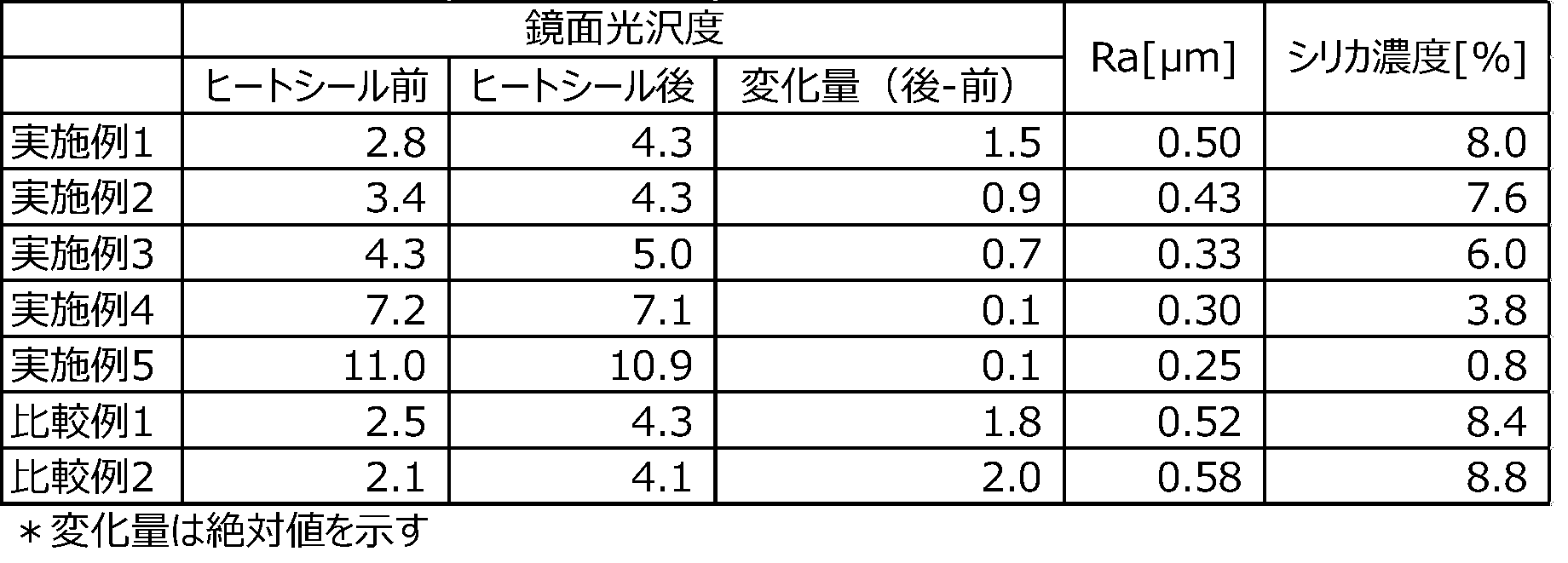
表1に示したように、実施例に係る電池用外装材は、熱シール前後での鏡面光沢度の変化量が1.8未満であるため、いずれも外観不良が無かった。一方、比較例1に係る電池用外装材は、熱シール前後での鏡面光沢度の変化量が1.8を超えていたため、外観不良が生じていた。なお、鏡面光沢度の変化量が1.8以上である場合を外観不良と判断したのは、熱シール前後での鏡面光沢度の変化量が0.5、1.0、1.5、1.8、2.0のサンプルを用意し、10人のモニターで外観変化があるかを判断したところ、1.8以上のサンプルは10人が外観変化したと判断したため、1.8以上であるものを外観不良とした。
なお、実施例に係る電池用外装材を用いてなる電池も上述した方法と同様にして測定した熱シール前後での鏡面光沢度の変化量は1.8未満であった。 As shown in Table 1, since the amount of change in the specular gloss before and after heat sealing was less than 1.8, the battery exterior materials according to the examples had no appearance defects. On the other hand, since the amount of change in the specular gloss before and after heat sealing was more than 1.8, the battery exterior material according to Comparative Example 1 had a poor appearance. Note that when the amount of change in specular gloss was 1.8 or more, it was determined that the appearance was poor because the amount of change in specular gloss before and after heat sealing was 0.5, 1.0, 1.5, 1 .8, 2.0 samples were prepared, and it was judged whether there was a change in appearance on 10 monitors. As a result, it was judged that 10 or more samples were changed in appearance, so that 1.8 or more samples were 1.8 or more. The thing was regarded as poor appearance.
In addition, the amount of change in the specular gloss before and after heat sealing, which was measured in the same manner as described above, for the battery using the battery case material according to the example was less than 1.8.
本発明の電池用外装材は、電池素子を収容する電池用外装材に極めて好適に使用することができる。
The battery packaging material of the present invention can be used very suitably for a battery packaging material that houses battery elements.
10 電池用外装材
11 表面保護層
12 基材層
13 接着剤層
14 バリア層
15 熱融着性樹脂層 DESCRIPTION OFSYMBOLS 10 Battery exterior material 11 Surface protective layer 12 Base material layer 13 Adhesive layer 14 Barrier layer 15 Heat-fusible resin layer
11 表面保護層
12 基材層
13 接着剤層
14 バリア層
15 熱融着性樹脂層 DESCRIPTION OF
Claims (5)
- 外側から順に、表面保護層、基材層、接着剤層、バリア層及び熱融着性樹脂層を備える電池用外装材であって、
前記熱融着性樹脂層同士が対向された状態で190℃、1.0MPa、6秒間の条件で熱シールされたときの前記表面保護層の熱シール部のJIS Z 8741(1997年)に準拠した鏡面光沢度と、前記表面保護層の非熱シール部のJIS Z 8741(1997年)に準拠した鏡面光沢度との差が1.8未満である電池用外装材。 In order from the outside, a battery exterior material comprising a surface protective layer, a base material layer, an adhesive layer, a barrier layer and a heat-fusible resin layer,
Conforms to JIS Z 8741 (1997) of the heat-sealed portion of the surface protective layer when heat-sealed at 190 ° C., 1.0 MPa, 6 seconds with the heat-fusible resin layers facing each other. The battery cladding | exterior_material whose difference of the specular glossiness and the specular glossiness based on JISZ8741 (1997) of the non-heat-sealing part of the said surface protective layer is less than 1.8. - 前記表面保護層は、前記基材層の側と反対側の表面に凹凸を有し、前記凹凸の算術平均粗さをRaとしたとき、前記Raが以下の式を満たす請求項1記載の電池用外装材。
0.20μm≦Ra≦0.50μm 2. The battery according to claim 1, wherein the surface protective layer has irregularities on a surface opposite to the substrate layer side, and when the arithmetic average roughness of the irregularities is Ra, the Ra satisfies the following formula. Exterior material.
0.20 μm ≦ Ra ≦ 0.50 μm - 前記表面保護層は、フィラーを含有する請求項1又は2記載の電池用外装材。 The battery exterior material according to claim 1, wherein the surface protective layer contains a filler.
- 前記フィラーは、酸化チタン、シリカ、タルク、クレー、重質炭酸カルシウム、軽質炭酸カルシウム、硫酸バリウム、ケイ酸カルシウム、合成ケイ酸塩、水酸化アルミニウム、及び、ケイ酸微粉末からなる群より選択される少なくとも1種を材料とする無機フィラーである請求項3記載の電池用外装材。 The filler is selected from the group consisting of titanium oxide, silica, talc, clay, heavy calcium carbonate, light calcium carbonate, barium sulfate, calcium silicate, synthetic silicate, aluminum hydroxide, and fine silicate powder. The battery exterior material according to claim 3, which is an inorganic filler made of at least one of the above materials.
- 少なくとも正極、負極、及び、電解質を備えた電池素子が電池用外装材により形成された熱シール部を備える包装体中に収容されている電池であって、
前記包装体の前記熱シール部のJIS Z 8741(1997年)に準拠した鏡面光沢度と、前記包装体の非熱シール部のJIS Z 8741(1997年)に準拠した鏡面光沢度との差が1.8未満である電池。 A battery in which a battery element including at least a positive electrode, a negative electrode, and an electrolyte is housed in a package including a heat seal portion formed of a battery exterior material,
There is a difference between the specular gloss according to JIS Z 8741 (1997) of the heat seal part of the package and the specular gloss according to JIS Z 8741 (1997) of the non-heat seal part of the package. A battery that is less than 1.8.
Priority Applications (2)
| Application Number | Priority Date | Filing Date | Title |
|---|---|---|---|
| CN201780039766.2A CN109417133B (en) | 2016-07-08 | 2017-07-10 | Battery exterior material and battery |
| JP2018526468A JP7188079B2 (en) | 2016-07-08 | 2017-07-10 | Battery exterior materials and batteries |
Applications Claiming Priority (2)
| Application Number | Priority Date | Filing Date | Title |
|---|---|---|---|
| JP2016-136452 | 2016-07-08 | ||
| JP2016136452 | 2016-07-08 |
Publications (1)
| Publication Number | Publication Date |
|---|---|
| WO2018008767A1 true WO2018008767A1 (en) | 2018-01-11 |
Family
ID=60901688
Family Applications (1)
| Application Number | Title | Priority Date | Filing Date |
|---|---|---|---|
| PCT/JP2017/025078 WO2018008767A1 (en) | 2016-07-08 | 2017-07-10 | Battery exterior material and battery |
Country Status (3)
| Country | Link |
|---|---|
| JP (1) | JP7188079B2 (en) |
| CN (1) | CN109417133B (en) |
| WO (1) | WO2018008767A1 (en) |
Cited By (3)
| Publication number | Priority date | Publication date | Assignee | Title |
|---|---|---|---|---|
| JP2019194952A (en) * | 2018-05-02 | 2019-11-07 | 昭和電工パッケージング株式会社 | Power storage device exterior material and power storage device |
| WO2020204185A1 (en) * | 2019-04-04 | 2020-10-08 | 大日本印刷株式会社 | Outer package material for electricity storage devices, method for producing same, and electricity storage device |
| US20220123406A1 (en) * | 2019-09-19 | 2022-04-21 | Contemporary Amperex Technology Co., Limited | Case, secondary battery, battery pack, vehicle, and method for manufacturing secondary battery |
Families Citing this family (2)
| Publication number | Priority date | Publication date | Assignee | Title |
|---|---|---|---|---|
| WO2020204186A1 (en) * | 2019-04-04 | 2020-10-08 | 大日本印刷株式会社 | Exterior material for electrical storage device, method for manufacturing same, and electrical storage device |
| WO2021020583A1 (en) * | 2019-08-01 | 2021-02-04 | 大日本印刷株式会社 | Exterior material for electrical storage device, method for manufacturing same, and electrical storage device |
Citations (3)
| Publication number | Priority date | Publication date | Assignee | Title |
|---|---|---|---|---|
| JP2014007131A (en) * | 2012-06-27 | 2014-01-16 | Dainippon Printing Co Ltd | Packaging material for electrochemical cell |
| JP2014049307A (en) * | 2012-08-31 | 2014-03-17 | Dainippon Printing Co Ltd | Packaging material for battery |
| JP2014175121A (en) * | 2013-03-07 | 2014-09-22 | Yuka Denshi Co Ltd | Laminate film for battery outer packaging and method for producing the same |
Family Cites Families (5)
| Publication number | Priority date | Publication date | Assignee | Title |
|---|---|---|---|---|
| JP4734888B2 (en) * | 2004-10-15 | 2011-07-27 | 凸版印刷株式会社 | Nonaqueous electrolyte battery exterior material manufacturing method and nonaqueous electrolyte battery manufacturing method |
| WO2007072736A1 (en) * | 2005-12-22 | 2007-06-28 | Showa Denko Packaging Co. | Laminate packing material for battery and laminate battery |
| JP5834483B2 (en) * | 2011-05-12 | 2015-12-24 | 凸版印刷株式会社 | Power storage device exterior materials |
| EP2979861B1 (en) * | 2013-03-29 | 2023-08-16 | Dai Nippon Printing Co., Ltd. | Decorative sheet and decorative resin molded article |
| JP6479323B2 (en) * | 2014-03-14 | 2019-03-06 | 昭和電工パッケージング株式会社 | Packaging material, battery outer case and battery |
-
2017
- 2017-07-10 CN CN201780039766.2A patent/CN109417133B/en active Active
- 2017-07-10 JP JP2018526468A patent/JP7188079B2/en active Active
- 2017-07-10 WO PCT/JP2017/025078 patent/WO2018008767A1/en active Application Filing
Patent Citations (3)
| Publication number | Priority date | Publication date | Assignee | Title |
|---|---|---|---|---|
| JP2014007131A (en) * | 2012-06-27 | 2014-01-16 | Dainippon Printing Co Ltd | Packaging material for electrochemical cell |
| JP2014049307A (en) * | 2012-08-31 | 2014-03-17 | Dainippon Printing Co Ltd | Packaging material for battery |
| JP2014175121A (en) * | 2013-03-07 | 2014-09-22 | Yuka Denshi Co Ltd | Laminate film for battery outer packaging and method for producing the same |
Cited By (5)
| Publication number | Priority date | Publication date | Assignee | Title |
|---|---|---|---|---|
| JP2019194952A (en) * | 2018-05-02 | 2019-11-07 | 昭和電工パッケージング株式会社 | Power storage device exterior material and power storage device |
| JP7226922B2 (en) | 2018-05-02 | 2023-02-21 | 株式会社レゾナック・パッケージング | Exterior material for power storage device and power storage device |
| WO2020204185A1 (en) * | 2019-04-04 | 2020-10-08 | 大日本印刷株式会社 | Outer package material for electricity storage devices, method for producing same, and electricity storage device |
| JP7435598B2 (en) | 2019-04-04 | 2024-02-21 | 大日本印刷株式会社 | Exterior material for power storage device, manufacturing method thereof, and power storage device |
| US20220123406A1 (en) * | 2019-09-19 | 2022-04-21 | Contemporary Amperex Technology Co., Limited | Case, secondary battery, battery pack, vehicle, and method for manufacturing secondary battery |
Also Published As
| Publication number | Publication date |
|---|---|
| JPWO2018008767A1 (en) | 2019-04-25 |
| JP7188079B2 (en) | 2022-12-13 |
| CN109417133A (en) | 2019-03-01 |
| CN109417133B (en) | 2021-10-29 |
Similar Documents
| Publication | Publication Date | Title |
|---|---|---|
| JP6020778B2 (en) | Battery packaging materials | |
| KR102220457B1 (en) | Packaging material for batteries | |
| WO2018008767A1 (en) | Battery exterior material and battery | |
| KR102230063B1 (en) | Battery packaging material | |
| JP7010332B2 (en) | Battery packaging material | |
| JP5708860B1 (en) | Battery packaging materials | |
| JP5704272B1 (en) | Battery packaging materials | |
| CN105556699B (en) | Packaging material for battery | |
| WO2015041281A1 (en) | Packaging material for cell | |
| JP6135233B2 (en) | Battery packaging materials | |
| JP6786802B2 (en) | Battery packaging material | |
| JP2023052778A (en) | Packaging material for battery and battery | |
| JP6136432B2 (en) | Battery packaging materials | |
| JP7456378B2 (en) | Polyethylene terephthalate film for battery packaging material, battery packaging material, manufacturing method of battery packaging material, and battery | |
| JP2014186983A (en) | Packaging material for battery | |
| JP5725070B2 (en) | Battery packaging materials | |
| JP6169115B2 (en) | Battery packaging materials | |
| JP5682688B1 (en) | Battery packaging materials | |
| JP6428843B2 (en) | Battery packaging materials | |
| JP6428841B2 (en) | Battery packaging materials | |
| JP2023153951A (en) | Polyethylene terephthalate film for packaging material for battery, packaging material for battery, method for manufacturing the same, and battery |
Legal Events
| Date | Code | Title | Description |
|---|---|---|---|
| ENP | Entry into the national phase |
Ref document number: 2018526468 Country of ref document: JP Kind code of ref document: A |
|
| 121 | Ep: the epo has been informed by wipo that ep was designated in this application |
Ref document number: 17824370 Country of ref document: EP Kind code of ref document: A1 |
|
| NENP | Non-entry into the national phase |
Ref country code: DE |
|
| 122 | Ep: pct application non-entry in european phase |
Ref document number: 17824370 Country of ref document: EP Kind code of ref document: A1 |