WO2018008313A1 - Head-up display - Google Patents
Head-up display Download PDFInfo
- Publication number
- WO2018008313A1 WO2018008313A1 PCT/JP2017/020763 JP2017020763W WO2018008313A1 WO 2018008313 A1 WO2018008313 A1 WO 2018008313A1 JP 2017020763 W JP2017020763 W JP 2017020763W WO 2018008313 A1 WO2018008313 A1 WO 2018008313A1
- Authority
- WO
- WIPO (PCT)
- Prior art keywords
- combiner
- unit case
- motor
- lead screw
- gear
- Prior art date
Links
Images


Classifications
-
- B—PERFORMING OPERATIONS; TRANSPORTING
- B60—VEHICLES IN GENERAL
- B60K—ARRANGEMENT OR MOUNTING OF PROPULSION UNITS OR OF TRANSMISSIONS IN VEHICLES; ARRANGEMENT OR MOUNTING OF PLURAL DIVERSE PRIME-MOVERS IN VEHICLES; AUXILIARY DRIVES FOR VEHICLES; INSTRUMENTATION OR DASHBOARDS FOR VEHICLES; ARRANGEMENTS IN CONNECTION WITH COOLING, AIR INTAKE, GAS EXHAUST OR FUEL SUPPLY OF PROPULSION UNITS IN VEHICLES
- B60K35/00—Arrangement of adaptations of instruments
-
- G—PHYSICS
- G02—OPTICS
- G02B—OPTICAL ELEMENTS, SYSTEMS OR APPARATUS
- G02B27/00—Optical systems or apparatus not provided for by any of the groups G02B1/00 - G02B26/00, G02B30/00
- G02B27/01—Head-up displays
Definitions
- the present invention relates to a head-up display that is incorporated in a dashboard of a car or the like and displays an image on a combiner, and particularly relates to a pop-up storage type head-up display that drives a combiner up and down and stores it in a case body. .
- HUD head-up display
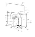
- FIGS. 6 and 7 show a rotary storage type HUD in which a combiner is rotated and stored in the case main body 20 among HUDs having a conventional combiner mounted in a dashboard of a car.
- a concave plate-shaped combiner 21 and a projection unit 22 for projecting an image toward the combiner 21 are incorporated in the case body 20 having an opening on the upper surface. .
- the combiner 21 is integrally provided with a rotation shaft 23 along one side thereof, and is located at a position where the case body 20 is closed by the rotation shaft 23 and a position where the case body 20 stands from the upper surface. It is provided so as to be freely rotatable.
- a helical gear 24 is provided at one end of the rotating shaft 23, and a worm gear 26 provided on the output shaft of the stepping motor 25 is screwed to the helical gear 24.
- a spiral spring 27 is provided at the other end of the rotating shaft 23 to urge the rotating shaft 23 around the axis in a direction in which the combiner 21 closes the opening.
- the combiner HUD projects the image from the projection unit 22 by raising the combiner 21 by the stepping motor 25 during use, and stores the image in the opening of the case body 20 by the urging force of the spiral spring 27 after use. It has become.
- the configuration of the HUD incorporated in such a dashboard is also disclosed in, for example, Patent Document 1 below.
- the present invention has been made in view of the above circumstances, and provides a pop-up storage type HUD that can handle a plurality of types of drive of a combiner with a simple structure, and thus can achieve a compact overall arrangement. It is an object to do.
- a head-up display has a plurality of guide shafts arranged in parallel between an upper flange and a lower flange in a case body in which an opening is formed in a top plate.
- a combiner in which the lower end is integrated with the outer periphery of the rotating shaft and the plate surface is arranged along the vertical direction, and is provided in the unit case. And a second motor that rotates the rotation shaft via a rotation mechanism.
- the unit motor is moved up and down by rotating the lead screw by the first motor. It is characterized by being caused to appear and disappear from the opening.
- the rotation mechanism includes a worm gear fixed to the output shaft of the second motor, and a helical gear that meshes with the worm gear and rotates the rotation shaft. To do.
- the first motor is fixed to the lower surface side of the lower flange, and a gear is fixed to the output shaft of the first motor protruding to the upper surface side of the lower flange. It is characterized by being screwed into a gear fixed to the lower end of the screw.
- a base portion having a diameter larger than that of the rotation shaft is fixed to the rotation shaft, and the base portion is formed with a screw constituting the rotation mechanism on the lower side.
- a combiner holder to which the combiner is attached is provided on the upper side.
- the combiner holder is arranged such that the upper part protrudes from the upper opening of the unit case, and the combiner is attached to the combiner holder.
- the unit case is provided with a pinion gear threadably engaged with the screw so as to be rotatable with an axis line parallel to the rotation shaft, and the helical gear having a larger diameter than the pinion gear is integrated with the pinion gear. It is characterized by being formed.
- a projection unit for projecting an image toward the combiner is disposed in the case body adjacent to the frame and the raising / lowering region of the unit case. is there.
- the unit case to which the nut screwed to the lead screw is fixed rises along the guide shaft, and the combiner provided at the upper part of the unit case is It protrudes outside the case body through the opening.
- the second motor provided in the unit case rotates the rotating shaft in the unit case and rotates the combiner around the rotating shaft, thereby receiving the image projected from the projection unit. Adjust the shadow angle.
- the unit case descends along the guide shaft and the combiner opens. It is stored in the case body through the section.
- the first and second motors it is possible to cope with a plurality of types of driving such as the vertical movement and rotation of the combiner with a simple structure, and thus the overall arrangement can be made compact. .
- a turning mechanism for turning the combiner a worm gear fixed to the output shaft of the second motor and a helical gear that meshes with the worm gear and turns the turning shaft are used. Even if an external force acts in the rotation direction from the combiner side after adjusting the receiving angle of the combiner, the worm gear can prevent the combiner from rotating.
- FIG. 5 is a side view of FIG. 4. It is a perspective view which shows schematic structure of the conventional rotation storing type HUD. It is a perspective view of the principal part of FIG. It is a perspective view which shows the conventional pop-up storage type HUD.
- FIG. 1 to 5 show an embodiment of a pop-up storage type head-up display 1 (hereinafter abbreviated as HUD) according to the present invention.
- HUD pop-up storage type head-up display 1
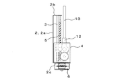
- body 1a of the HUD 1 an opening is formed in the top plate 1b, and a frame 2 is fixed inside.
- the frame 2 is a plate-like member in which an upper flange 2b and a lower flange 2c that are bent horizontally are formed at the upper and lower ends of the wall plate 2a.
- 2 Two guide shafts 3 are provided at intervals in the horizontal direction.
- a box-shaped unit case 4 having an upper surface opened is provided so as to be movable up and down.
- a lead screw 5 is disposed between the guide shafts 3 through the unit case 4 and upper and lower ends thereof are rotatably supported by the upper flange 2b and the lower flange 2c, respectively.
- a stepping motor (first motor) 6 is fixed adjacent to the lower end portion of the lead screw 5, and the output shaft of the stepping motor 6 protruding on the upper surface side of the lower flange 2c is used.
- the gear 7 is fixed.
- the gear 7 is screwed to a gear 8 fixed to the lower end portion of the lead screw 5, and a nut 9 fixed to the unit case 4 is screwed to the lead screw 5.
- a rotating shaft 10 is arranged in a horizontal direction and supported so as to be rotatable around an axis.
- a base portion 11 having a diameter larger than that of the rotation shaft 10 is fixed to the central portion of the rotation shaft 10.
- the base portion 11 has a screw 11 a formed on the lower half of the circumference thereof, and a flat plate combiner holder 12 provided in parallel with the rotary shaft 10 on the outer circumference of the upper side.
- the combiner holder 12 is arranged with the upper part protruding from the upper opening of the unit case 4, and the lower end part of the combiner 13 arranged with the plate surface along the vertical direction is attached to the combiner holder 12. Yes.
- a pinion gear 14 screwed with the screw 11 a is rotatably provided with an axis line parallel to the rotation shaft 10, and the pinion gear 14 has a helical gear having a larger diameter than the pinion gear 14. 15 is integrally formed.
- a tilting stepping motor (second motor) 16 is mounted in the unit case 4 with its axis line oriented in the vertical direction.
- a worm gear 17 fixed to the output shaft of the tilting stepping motor 16 is engaged with the helical gear 15.
- the screw 11 a of the base 11, the pinion gear 14, the helical gear 15, and the worm gear 17 constitute a turning mechanism for turning the turning shaft 10.
- a projection unit (not shown) for projecting an image toward the combiner 13 is disposed adjacent to the lift areas of the frame 2 and the unit case 4. .
- the unit case 4 to which the nut 9 screwed to the lead screw 5 is fixed rises along the guide shaft 3.
- the combiner 13 provided on the upper part of the unit case 4 passes through the opening and protrudes outside the case body 1a.
- the combiner 13 is raised by the tilting stepping motor 16, and the lead screw 5 is rotated in the opposite direction by the stepping motor 5, thereby lowering the unit case 4 along the guide shaft 3. 4 and FIG. 5, the combiner 13 is stored in the case main body 1a.
- the pop-up storage type HUD 1 by using the two stepping motors 6 and the tilting stepping motor 16, it is possible to cope with a plurality of types of driving such as the vertical movement and rotation of the combiner 13 with a simple structure. Therefore, the overall arrangement can be made compact.
- a worm gear 17 is provided on the output shaft of the tilting stepping motor 16, the helical gear 15 is engaged with the worm gear 17, the helical gear 15 is integrated, and the rotating shaft 10 is rotated by the pinion gear 14. Therefore, after adjusting the receiving angle of the combiner 13, even when an external force is applied in the rotation direction from the combiner 13 side, the tilt stepping motor 16 is rotated by the worm gear 17 and the combiner 13 is rotated. Can be prevented.
- 1 pop-up storage type HUD 1a case body, 1b top plate, 2 frame, 2b upper flange, 2c lower flange, 3 guide shaft, 4 unit case, 5 lead screw, 6 stepping motor (first motor), 9 nut 10, rotating shaft, 13 combiner, 15 helical gear, 16 tilting stepping motor (second motor), 17 worm gear
Abstract
Provided is a pop-up retractable head-up display (HUD) which has a simple structure capable of supporting multiple types of movement of a combiner, thereby allowing compact overall layout. More specifically, the interior of a case body 1a is equipped with: a frame 2 which has a plurality of guide shafts 3 arranged between an upper flange 2b and a lower flange 2c; a lead screw 5 which is rotatably supported parallel to the guide shafts 3 by the frame 2; a unit case 4 which is provided so as to be vertically movable along the guide shafts of the frame 2 and which has a nut 9 fixed thereto, the nut 9 being screwably engaged with the lead screw 5; a first motor 6 which rotationally drives the lead screw 5; a turning shaft 10 which is disposed in the horizontal direction within the unit case 4 and supported turnably about the axis; a combiner 13 which is integrated with the outer periphery of the turning shaft 10 and disposed with the plate surface thereof aligned with the vertical direction; and a second motor 16 which is provided within the unit case 4 so as to turn the turning shaft 10 by means of a turning mechanism.
Description
本発明は、車のダッシュボード等に組み込まれてコンバイナに映像を表示させるヘッドアップディスプレイであって、特にコンバイナを上下駆動してケース本体内に格納するポップアップ格納タイプのヘッドアップディスプレイに関するものである。
The present invention relates to a head-up display that is incorporated in a dashboard of a car or the like and displays an image on a combiner, and particularly relates to a pop-up storage type head-up display that drives a combiner up and down and stores it in a case body. .
近年、乗用自動車等の各種の車両において、凹面板状のコンバイナフロントに映像を反射させて運転者の視界内に運転情報を重ねて表示させるヘッドアップディスプレイ(以下、HUDと略す。)が採用されている。
2. Description of the Related Art In recent years, a head-up display (hereinafter abbreviated as HUD) that reflects an image on a concave plate-shaped combiner front and displays driving information in a driver's field of view has been adopted in various vehicles such as passenger cars. ing.
図6および図7は、車のダッシュボード内に取り付けられる従来のコンバイナを備えたHUDのうち、コンバイナを回転させてケース本体20に格納する回転格納タイプのHUDを示すもので、このコンバイナHUDは、上面に開口部が形成されたケース本体20の内部に、凹面板状のコンバイナ21と、このコンバイナ21に向けて映像を投射する投影ユニット22とが組み込まれることにより概略構成されたものである。
6 and 7 show a rotary storage type HUD in which a combiner is rotated and stored in the case main body 20 among HUDs having a conventional combiner mounted in a dashboard of a car. A concave plate-shaped combiner 21 and a projection unit 22 for projecting an image toward the combiner 21 are incorporated in the case body 20 having an opening on the upper surface. .
ここで、コンバイナ21は、その一辺に沿って回動軸23が一体的に設けられており、この回動軸23によってケース本体20を塞ぐ位置と、当該ケース本体20の上面から起立する位置の間を回動自在に設けられている。
Here, the combiner 21 is integrally provided with a rotation shaft 23 along one side thereof, and is located at a position where the case body 20 is closed by the rotation shaft 23 and a position where the case body 20 stands from the upper surface. It is provided so as to be freely rotatable.
そして、回動軸23の一方の端部にヘリカルギヤ24が設けられ、このヘリカルギヤ24にステッピングモータ25の出力軸に設けられたウオームギヤ26が螺合されている。また、回動軸23の他方の端部には、コンバイナ21が開口部を塞ぐ方向に回動軸23を軸線廻りに付勢する渦巻きバネ27が設けられている。
A helical gear 24 is provided at one end of the rotating shaft 23, and a worm gear 26 provided on the output shaft of the stepping motor 25 is screwed to the helical gear 24. A spiral spring 27 is provided at the other end of the rotating shaft 23 to urge the rotating shaft 23 around the axis in a direction in which the combiner 21 closes the opening.
これにより上記コンバイナHUDは、使用時にステッピングモータ25によってコンバイナ21を起立させて投影ユニット22から映像を投射するとともに、使用後は渦巻きバネ27の付勢力によってケース本体20の開口部内に収納するようになっている。なお、このようなダッシュボード内に組み込まれるHUDの構成に関しては、例えば下記特許文献1においても開示されている。
As a result, the combiner HUD projects the image from the projection unit 22 by raising the combiner 21 by the stepping motor 25 during use, and stores the image in the opening of the case body 20 by the urging force of the spiral spring 27 after use. It has become. The configuration of the HUD incorporated in such a dashboard is also disclosed in, for example, Patent Document 1 below.
一方、上記構成からなるコンバイナ21を回転させてケース本体20に格納する回転格納タイプのHUDの他に、図8に示すような、コンバイナ30を上下駆動してケース本体31内に格納するポップアップ格納タイプのHUDも開発されている。
On the other hand, in addition to the rotary storage type HUD in which the combiner 21 having the above-described configuration is rotated and stored in the case body 20, the pop-up storage in which the combiner 30 is driven up and down and stored in the case body 31 as shown in FIG. A type of HUD has also been developed.
このようなポップアップ格納タイプのHUDにおいては、コンバイナ30を上下駆動した後に、ケース本体31内の投影ユニットから映像を投射する際に、コンバイナ30を、下端部を中心として回動させることにより受影角度の調整(チルト調整)を行う必要がある。
In such a pop-up storage type HUD, when the image is projected from the projection unit in the case body 31 after the combiner 30 is driven up and down, the image is received by rotating the combiner 30 around the lower end. It is necessary to adjust the angle (tilt adjustment).
このため、上記コンバイナ30に対する複数の駆動を、図6および図7に示した回転格納タイプのHUDのように1つのステッピングモータで行わせようとすると、構造が極めて複雑になるとともに、装置の大型化も招くという問題点があった。
For this reason, if a plurality of driving operations for the combiner 30 are performed by a single stepping motor such as the rotary storage type HUD shown in FIGS. 6 and 7, the structure becomes extremely complicated and the size of the apparatus becomes large. There was also a problem of inviting it.
本発明は、上記事情に鑑みてなされたものであり、簡易な構造によってコンバイナの複数種の駆動に対応することができ、よって全体配置のコンパクト化を図ることができるポップアップ格納タイプのHUDを提供することを課題とするものである。
The present invention has been made in view of the above circumstances, and provides a pop-up storage type HUD that can handle a plurality of types of drive of a combiner with a simple structure, and thus can achieve a compact overall arrangement. It is an object to do.
上記課題を解決するため、本発明に係るヘッドアップディスプレイは、天板に開口部が形成されたケース本体の内部に、上部フランジと下部フランジとの間に複数本のガイド軸が平行に配設されたフレームと、このフレームに上記ガイド軸と平行に配設されて回転自在に支承されたリードスクリューと、上記フレームの上記ガイド軸に沿って上下方向に移動自在に設けられるとともに、上記リードスクリューと螺合するナットが固定されたユニットケースと、上記リードスクリューを回転駆動する第1のモータと、上記ユニットケース内に水平方向に配置されて軸線廻りに回動自在に支持された回動軸と、この回動軸の外周に下端部が一体化されるとともに板面を鉛直方向に沿わせて配置されたコンバイナと、上記ユニットケース内に設けられて回動機構を介して上記回動軸を回動させる第2のモータとを備えてなり、上記第1のモータによって上記リードスクリューを回転させることにより上記ユニットケースを昇降させて上記コンバイナを上記開口部から出没させるようにしたことを特徴とするものである。
In order to solve the above problems, a head-up display according to the present invention has a plurality of guide shafts arranged in parallel between an upper flange and a lower flange in a case body in which an opening is formed in a top plate. A frame, a lead screw disposed parallel to the guide shaft and rotatably supported on the frame, and a lead screw that is vertically movable along the guide shaft of the frame. A unit case in which a nut to be screwed is fixed, a first motor that rotationally drives the lead screw, and a rotation shaft that is disposed in the unit case in a horizontal direction and is rotatably supported around an axis. And a combiner in which the lower end is integrated with the outer periphery of the rotating shaft and the plate surface is arranged along the vertical direction, and is provided in the unit case. And a second motor that rotates the rotation shaft via a rotation mechanism. The unit motor is moved up and down by rotating the lead screw by the first motor. It is characterized by being caused to appear and disappear from the opening.
本発明において、上記回動機構が、上記第2のモータの出力軸に固定されたウオームギヤと、このウオームギヤに歯合するとともに上記回動軸を回動させるヘリカルギヤとを備えてなることを特徴とするものである。
In the present invention, the rotation mechanism includes a worm gear fixed to the output shaft of the second motor, and a helical gear that meshes with the worm gear and rotates the rotation shaft. To do.
本発明において、上記下部フランジの下面側には上記第1のモータが固定され、上記下部フランジの上面側に突出する上記第1モータの出力軸に歯車が固定されており、上記歯車は上記リードスクリューの下端部に固定された歯車に螺合されていることを特徴とするものである。
In the present invention, the first motor is fixed to the lower surface side of the lower flange, and a gear is fixed to the output shaft of the first motor protruding to the upper surface side of the lower flange. It is characterized by being screwed into a gear fixed to the lower end of the screw.
本発明において、上記回動軸には当該回動軸よりも大径の基台部が固定されており、上記基台部は、下部側に上記回動機構を構成するネジが形成されるとともに、上部側に上記コンバイナが取り付けられるコンバイナホルダが設けられていることを特徴とするものである。
In the present invention, a base portion having a diameter larger than that of the rotation shaft is fixed to the rotation shaft, and the base portion is formed with a screw constituting the rotation mechanism on the lower side. A combiner holder to which the combiner is attached is provided on the upper side.
本発明において、上記コンバイナホルダは、上部を上記ユニットケースの上部開口から突出させて配置されており、当該コンバイナホルダに上記コンバイナが取り付けられていることを特徴とするものである。
In the present invention, the combiner holder is arranged such that the upper part protrudes from the upper opening of the unit case, and the combiner is attached to the combiner holder.
本発明において、上記ユニットケースには、上記ネジと螺合するピニオンギヤが軸線を上記回動軸と平行にして回転自在に設けられており、上記ピニオンギヤには当該ピニオンギヤより大径の上記ヘリカルギヤが一体に形成されていることを特徴とするものである。
In the present invention, the unit case is provided with a pinion gear threadably engaged with the screw so as to be rotatable with an axis line parallel to the rotation shaft, and the helical gear having a larger diameter than the pinion gear is integrated with the pinion gear. It is characterized by being formed.
本発明において、上記ケース本体内には、上記フレームおよび上記ユニットケースの昇降領域に隣接して、上記コンバイナへ向けて映像を投射するための投影ユニットが配置されていることを特徴とするものである。
In the present invention, a projection unit for projecting an image toward the combiner is disposed in the case body adjacent to the frame and the raising / lowering region of the unit case. is there.
本発明では、第1のモータによってリードスクリューを回転させると、当該リードスクリューに螺合するナットが固定されたユニットケースがガイド軸に沿って上昇し、ユニットケースの上部に設けられているコンバイナが開口部を通過してケース本体の外部に突出する。
In the present invention, when the lead screw is rotated by the first motor, the unit case to which the nut screwed to the lead screw is fixed rises along the guide shaft, and the combiner provided at the upper part of the unit case is It protrudes outside the case body through the opening.
この状態で、ユニットケース内に設けられた第2のモータによってユニットケース内の回動軸を回転させて当該回動軸回りにコンバイナを回動させることにより、投影ユニットから投射される映像の受影角度を調整する。
In this state, the second motor provided in the unit case rotates the rotating shaft in the unit case and rotates the combiner around the rotating shaft, thereby receiving the image projected from the projection unit. Adjust the shadow angle.
また、HUDの使用後は、上記第2のモータによってコンバイナを起立状態にして、第1のモータによりリードスクリューを反対方向に回転させると、ユニットケースがガイド軸に沿って降下し、コンバイナが開口部を介してケース本体内に格納される。
After using the HUD, when the combiner is raised by the second motor and the lead screw is rotated in the opposite direction by the first motor, the unit case descends along the guide shaft and the combiner opens. It is stored in the case body through the section.
このように、第1および第2のモータを用いることにより、簡易な構造によってコンバイナの上下動や回動といった複数種の駆動に対応することができ、よって全体配置のコンパクト化を図ることができる。
As described above, by using the first and second motors, it is possible to cope with a plurality of types of driving such as the vertical movement and rotation of the combiner with a simple structure, and thus the overall arrangement can be made compact. .
また、コンバイナを回動させる回動機構として、第2のモータの出力軸に固定されたウオームギヤと、このウオームギヤに歯合するとともに上記回動軸を回動させるヘリカルギヤとを用いているために、コンバイナの受影角度を調整した後に、コンバイナ側から回動方向に外力が作用しても、上記ウオームギヤによって上記コンバイナが回動することを防ぐことができる。
Further, as a turning mechanism for turning the combiner, a worm gear fixed to the output shaft of the second motor and a helical gear that meshes with the worm gear and turns the turning shaft are used. Even if an external force acts in the rotation direction from the combiner side after adjusting the receiving angle of the combiner, the worm gear can prevent the combiner from rotating.
図1~図5は、本発明に係るポップアップ格納タイプのヘッドアップディスプレイ1(以下、HUDと略す。)の一実施形態を示すものである。このHUD1のケース本体1aは、天板1bに開口部が形成されるとともに、内部にはフレーム2が固定されている。このフレーム2は、壁板2aの上下端部に、水平に屈曲された上部フランジ2bおよび下部フランジ2cが形成された板状の部材で、上部フランジ2bと下部フランジ2cとの間には、2本のガイド軸3が水平方向に間隔をおいて設けられている。
1 to 5 show an embodiment of a pop-up storage type head-up display 1 (hereinafter abbreviated as HUD) according to the present invention. In the case body 1a of the HUD 1, an opening is formed in the top plate 1b, and a frame 2 is fixed inside. The frame 2 is a plate-like member in which an upper flange 2b and a lower flange 2c that are bent horizontally are formed at the upper and lower ends of the wall plate 2a. Between the upper flange 2b and the lower flange 2c, 2 Two guide shafts 3 are provided at intervals in the horizontal direction.
そして、これらガイド軸3に沿って、上面が開口する箱状のユニットケース4が昇降自在に設けられている。また、これらガイド軸3間には、ユニットケース4を貫通してリードスクリュー5が配設され、その上下端部が各々、上部フランジ2bと下部フランジ2cとに回転自在に支持されている。他方、下部フランジ2cの下面側には、リードスクリュー5の下端部に隣接してステッピングモータ(第1のモータ)6が固定され、下部フランジ2cの上面側に突出するステッピングモータ6の出力軸に歯車7が固定されている。
And along these guide shafts 3, a box-shaped unit case 4 having an upper surface opened is provided so as to be movable up and down. A lead screw 5 is disposed between the guide shafts 3 through the unit case 4 and upper and lower ends thereof are rotatably supported by the upper flange 2b and the lower flange 2c, respectively. On the other hand, on the lower surface side of the lower flange 2c, a stepping motor (first motor) 6 is fixed adjacent to the lower end portion of the lead screw 5, and the output shaft of the stepping motor 6 protruding on the upper surface side of the lower flange 2c is used. The gear 7 is fixed.
そして、この歯車7がリードスクリュー5の下端部に固定された歯車8に螺合されるとともに、ユニットケース4に固定されたナット9がリードスクリュー5に螺合されている。これにより、ステッピングモータ6を回転させると、リードスクリュー5が回転するとともにこれと螺合するナット9が固定されたユニットケース4がケース本体1a内において昇降するようになっている。
The gear 7 is screwed to a gear 8 fixed to the lower end portion of the lead screw 5, and a nut 9 fixed to the unit case 4 is screwed to the lead screw 5. Thus, when the stepping motor 6 is rotated, the unit case 4 to which the lead screw 5 is rotated and the nut 9 screwed with the lead screw 5 is fixed is moved up and down in the case main body 1a.
このユニットケース4内には、回動軸10が水平方向に配置されて軸線廻りに回動自在に支持されている。この回動軸10の中心部には、当該回動軸10よりも大径の基台部11が固定されている。この基台部11は、下部側の半周にネジ11aが形成されるとともに、上部側の外周に平板状のコンバイナホルダ12が回動軸10と平行に設けられている。
In this unit case 4, a rotating shaft 10 is arranged in a horizontal direction and supported so as to be rotatable around an axis. A base portion 11 having a diameter larger than that of the rotation shaft 10 is fixed to the central portion of the rotation shaft 10. The base portion 11 has a screw 11 a formed on the lower half of the circumference thereof, and a flat plate combiner holder 12 provided in parallel with the rotary shaft 10 on the outer circumference of the upper side.
このコンバイナホルダ12は、上部をユニットケース4の上部開口から突出させて配置されており、このコンバイナホルダ12に、板面を鉛直方向に沿わせて配置されたコンバイナ13の下端部が取り付けられている。
The combiner holder 12 is arranged with the upper part protruding from the upper opening of the unit case 4, and the lower end part of the combiner 13 arranged with the plate surface along the vertical direction is attached to the combiner holder 12. Yes.
他方、ユニットケース4内には、上記ネジ11aと螺合するピニオンギヤ14が軸線を回動軸10と平行にして回転自在に設けられており、このピニオンギヤ14には、ピニオンギヤ14より大径のヘリカルギヤ15が一体に形成されている。
On the other hand, in the unit case 4, a pinion gear 14 screwed with the screw 11 a is rotatably provided with an axis line parallel to the rotation shaft 10, and the pinion gear 14 has a helical gear having a larger diameter than the pinion gear 14. 15 is integrally formed.
また、このユニットケース4内には、チルト用ステッピングモータ(第2のモータ)16がその軸線を鉛直方向に向けて取り付けられている。そして、このチルト用ステッピングモータ16の出力軸に固定されたウオームギヤ17が、上記ヘリカルギヤ15に歯合されている。そして、基台部11のネジ11a、ピニオンギヤ14、ヘリカルギヤ15およびウオームギヤ17によって、回動軸10を回動させるための回動機構が構成されている。
Further, a tilting stepping motor (second motor) 16 is mounted in the unit case 4 with its axis line oriented in the vertical direction. A worm gear 17 fixed to the output shaft of the tilting stepping motor 16 is engaged with the helical gear 15. The screw 11 a of the base 11, the pinion gear 14, the helical gear 15, and the worm gear 17 constitute a turning mechanism for turning the turning shaft 10.
そして、このケース本体1a内には、これらフレーム2およびユニットケース4の昇降領域に隣接して、上記コンバイナ13へ向けて映像を投射するための投影ユニット(図示を略す。)が配置されている。
In the case main body 1a, a projection unit (not shown) for projecting an image toward the combiner 13 is disposed adjacent to the lift areas of the frame 2 and the unit case 4. .
以上の構成からなるポップアップ格納タイプのHUD1においては、ステッピングモータ6によってリードスクリュー5を回転させると、このリードスクリュー5に螺合するナット9が固定されたユニットケース4がガイド軸3に沿って上昇し、図1~図3に示すように、ユニットケース4の上部に設けられているコンバイナ13が開口部を通過してケース本体1aの外部に突出する。
In the pop-up storage type HUD 1 configured as described above, when the lead screw 5 is rotated by the stepping motor 6, the unit case 4 to which the nut 9 screwed to the lead screw 5 is fixed rises along the guide shaft 3. As shown in FIGS. 1 to 3, the combiner 13 provided on the upper part of the unit case 4 passes through the opening and protrudes outside the case body 1a.
この状態で、ユニットケース4内に設けられたチルト用ステッピングモータ16によって、ウオームギヤ17と歯合するヘリカルギヤ15を回動させることにより、ピニオンギヤ14と歯合する回動軸10を回動させてコンバイナ13を回動させることにより、上記投影ユニットから投射される映像の受影方向への傾斜角度を調整する。
In this state, by rotating the helical gear 15 that meshes with the worm gear 17 by the tilting stepping motor 16 provided in the unit case 4, the pivot shaft 10 that meshes with the pinion gear 14 is rotated and the combiner is rotated. By rotating 13, the inclination angle of the image projected from the projection unit in the receiving direction is adjusted.
また、使用後は、チルト用ステッピングモータ16によってコンバイナ13を起立状態にして、ステッピングモータ5によりリードスクリュー5を反対方向に回転させることにより、ユニットケース4をガイド軸3に沿って降下させ、図4および図5に示すように、コンバイナ13をケース本体1a内に格納する。
After use, the combiner 13 is raised by the tilting stepping motor 16, and the lead screw 5 is rotated in the opposite direction by the stepping motor 5, thereby lowering the unit case 4 along the guide shaft 3. 4 and FIG. 5, the combiner 13 is stored in the case main body 1a.
このように、上記ポップアップ格納タイプのHUD1によれば、2つのステッピングモータ6、チルト用ステッピングモータ16を用いることにより、簡易な構造によってコンバイナ13の上下動や回動といった複数種の駆動に対応することができ、よって全体配置のコンパクト化を図ることができる。
As described above, according to the pop-up storage type HUD 1, by using the two stepping motors 6 and the tilting stepping motor 16, it is possible to cope with a plurality of types of driving such as the vertical movement and rotation of the combiner 13 with a simple structure. Therefore, the overall arrangement can be made compact.
加えて、チルト用ステッピングモータ16の出力軸にウオームギヤ17を設け、このウオームギヤ17にヘリカルギヤ15を歯合させて、当該ヘリカルギヤ15を一体化されてピニオンギヤ14によって回動軸10を回動させているために、コンバイナ13の受影角度を調整した後に、コンバイナ13側から回動方向に外力が作用した場合においても、ウオームギヤ17によってチルト用ステッピングモータ16が回転してコンバイナ13が回動することを防ぐことができる。
In addition, a worm gear 17 is provided on the output shaft of the tilting stepping motor 16, the helical gear 15 is engaged with the worm gear 17, the helical gear 15 is integrated, and the rotating shaft 10 is rotated by the pinion gear 14. Therefore, after adjusting the receiving angle of the combiner 13, even when an external force is applied in the rotation direction from the combiner 13 side, the tilt stepping motor 16 is rotated by the worm gear 17 and the combiner 13 is rotated. Can be prevented.
1 ポップアップ格納タイプのHUD、1a ケース本体、1b 天板、2 フレーム、2b 上部フランジ、2c 下部フランジ、3 ガイド軸、4 ユニットケース、5 リードスクリュー、6 ステッピングモータ(第1のモータ)、9 ナット、10 回動軸、13 コンバイナ、15 ヘリカルギヤ、16 チルト用ステッピングモータ(第2のモータ)、17 ウオームギヤ
1 pop-up storage type HUD, 1a case body, 1b top plate, 2 frame, 2b upper flange, 2c lower flange, 3 guide shaft, 4 unit case, 5 lead screw, 6 stepping motor (first motor), 9 nut 10, rotating shaft, 13 combiner, 15 helical gear, 16 tilting stepping motor (second motor), 17 worm gear
Claims (7)
- 天板に開口部が形成されたケース本体の内部に、上部フランジと下部フランジとの間に複数本のガイド軸が平行に配設されたフレームと、このフレームに上記ガイド軸と平行に配設されて回転自在に支承されたリードスクリューと、上記フレームの上記ガイド軸に沿って上下方向に移動自在に設けられるとともに、上記リードスクリューと螺合するナットが固定されたユニットケースと、上記リードスクリューを回転駆動する第1のモータと、上記ユニットケース内に水平方向に配置されて軸線廻りに回動自在に支持された回動軸と、この回動軸の外周に下端部が一体化されるとともに板面を鉛直方向に沿わせて配置されたコンバイナと、上記ユニットケース内に設けられて回動機構を介して上記回動軸を回動させる第2のモータとを備えてなり、
上記第1のモータによって上記リードスクリューを回転させることにより上記ユニットケースを昇降させて上記コンバイナを上記開口部から出没させるようにしたことを特徴とするヘッドアップディスプレイ。 A frame in which a plurality of guide shafts are arranged in parallel between the upper flange and the lower flange inside the case body having an opening formed in the top plate, and the frame is arranged in parallel with the guide shaft. A lead screw that is rotatably supported, a unit case that is provided so as to be movable in the vertical direction along the guide shaft of the frame, and in which a nut that engages with the lead screw is fixed, and the lead screw A lower end portion is integrated with an outer periphery of the first motor, a rotary shaft that is horizontally disposed in the unit case and is rotatably supported around the axis. And a combiner arranged with the plate surface along the vertical direction, and a second motor that is provided in the unit case and rotates the rotation shaft via a rotation mechanism. Ri,
A head-up display, wherein the lead screw is rotated by the first motor to raise and lower the unit case so that the combiner protrudes and retracts from the opening. - 上記回動機構は、上記第2のモータの出力軸に固定されたウオームギヤと、このウオームギヤに歯合するとともに上記回動軸を回動させるヘリカルギヤとを備えてなることを特徴とする請求項1に記載のヘッドアップディスプレイ。 2. The rotating mechanism includes a worm gear fixed to the output shaft of the second motor, and a helical gear that meshes with the worm gear and rotates the rotating shaft. The head-up display described in 1.
- 上記下部フランジの下面側には上記第1のモータが固定され、上記下部フランジの上面側に突出する上記第1モータの出力軸に歯車が固定されており、
上記歯車は上記リードスクリューの下端部に固定された歯車に螺合されていることを特徴とする請求項1に記載のヘッドアップディスプレイ。 The first motor is fixed to the lower surface side of the lower flange, and a gear is fixed to the output shaft of the first motor protruding to the upper surface side of the lower flange,
The head-up display according to claim 1, wherein the gear is screwed into a gear fixed to a lower end portion of the lead screw. - 上記回動軸には当該回動軸よりも大径の基台部が固定されており、
上記基台部は、下部側に上記回動機構を構成するネジが形成されるとともに、上部側に上記コンバイナが取り付けられるコンバイナホルダが設けられていることを特徴とする請求項1に記載のヘッドアップディスプレイ。 A base portion having a diameter larger than that of the rotation shaft is fixed to the rotation shaft.
2. The head according to claim 1, wherein the base portion is provided with a screw forming the rotating mechanism on a lower side and a combiner holder to which the combiner is attached on an upper side. Up display. - 上記コンバイナホルダは、上部を上記ユニットケースの上部開口から突出させて配置されており、当該コンバイナホルダに上記コンバイナが取り付けられていることを特徴とする請求項4に記載のヘッドアップディスプレイ。 The head-up display according to claim 4, wherein the combiner holder is disposed with an upper portion protruding from an upper opening of the unit case, and the combiner is attached to the combiner holder.
- 上記ユニットケースには、上記ネジと螺合するピニオンギヤが軸線を上記回動軸と平行にして回転自在に設けられており、
上記ピニオンギヤには当該ピニオンギヤより大径の上記ヘリカルギヤが一体に形成されていることを特徴とする請求項4に記載のヘッドアップディスプレイ。 In the unit case, a pinion gear that is screwed with the screw is rotatably provided with an axis parallel to the rotation shaft,
5. The head-up display according to claim 4, wherein the helical gear having a larger diameter than that of the pinion gear is integrally formed with the pinion gear. - 上記ケース本体内には、上記フレームおよび上記ユニットケースの昇降領域に隣接して、上記コンバイナへ向けて映像を投射するための投影ユニットが配置されていることを特徴とする請求項1に記載のヘッドアップディスプレイ。 The projection unit for projecting an image toward the combiner is disposed in the case main body adjacent to the frame and the raising / lowering region of the unit case. Head-up display.
Applications Claiming Priority (2)
| Application Number | Priority Date | Filing Date | Title |
|---|---|---|---|
| JP2016134120A JP2018002050A (en) | 2016-07-06 | 2016-07-06 | Head-up display |
| JP2016-134120 | 2016-07-06 |
Publications (1)
| Publication Number | Publication Date |
|---|---|
| WO2018008313A1 true WO2018008313A1 (en) | 2018-01-11 |
Family
ID=60912641
Family Applications (1)
| Application Number | Title | Priority Date | Filing Date |
|---|---|---|---|
| PCT/JP2017/020763 WO2018008313A1 (en) | 2016-07-06 | 2017-06-05 | Head-up display |
Country Status (2)
| Country | Link |
|---|---|
| JP (1) | JP2018002050A (en) |
| WO (1) | WO2018008313A1 (en) |
Cited By (2)
| Publication number | Priority date | Publication date | Assignee | Title |
|---|---|---|---|---|
| CN108720282A (en) * | 2018-06-13 | 2018-11-02 | 韩智强 | A kind of ideological education teaching desk |
| WO2020021773A1 (en) * | 2018-07-23 | 2020-01-30 | 株式会社Jvcケンウッド | Virtual image display device |
Families Citing this family (2)
| Publication number | Priority date | Publication date | Assignee | Title |
|---|---|---|---|---|
| CN110588349B (en) * | 2019-09-23 | 2021-12-21 | 株洲时代新材料科技股份有限公司 | Electric adjustment method for suspended instrument desk and electric adjustment suspended instrument desk |
| KR20220045671A (en) | 2020-10-06 | 2022-04-13 | 현대자동차주식회사 | Device for automatically adjusting angle of monitor mounted on seat back of vehicle |
Citations (6)
| Publication number | Priority date | Publication date | Assignee | Title |
|---|---|---|---|---|
| WO2006027980A1 (en) * | 2004-09-07 | 2006-03-16 | Pioneer Corporation | Electronic apparatus |
| JP2012061987A (en) * | 2010-09-17 | 2012-03-29 | Toshiba Corp | Display device |
| JP2014163962A (en) * | 2013-02-21 | 2014-09-08 | Yazaki Corp | In-vehicle display device |
| JP2014164234A (en) * | 2013-02-27 | 2014-09-08 | Yazaki Corp | In-vehicle display device |
| JP2015102746A (en) * | 2013-11-26 | 2015-06-04 | アルパイン株式会社 | Display device |
| JP2015219356A (en) * | 2014-05-16 | 2015-12-07 | ミネベア株式会社 | Tilt mechanism and display device having the same |
-
2016
- 2016-07-06 JP JP2016134120A patent/JP2018002050A/en not_active Ceased
-
2017
- 2017-06-05 WO PCT/JP2017/020763 patent/WO2018008313A1/en active Application Filing
Patent Citations (6)
| Publication number | Priority date | Publication date | Assignee | Title |
|---|---|---|---|---|
| WO2006027980A1 (en) * | 2004-09-07 | 2006-03-16 | Pioneer Corporation | Electronic apparatus |
| JP2012061987A (en) * | 2010-09-17 | 2012-03-29 | Toshiba Corp | Display device |
| JP2014163962A (en) * | 2013-02-21 | 2014-09-08 | Yazaki Corp | In-vehicle display device |
| JP2014164234A (en) * | 2013-02-27 | 2014-09-08 | Yazaki Corp | In-vehicle display device |
| JP2015102746A (en) * | 2013-11-26 | 2015-06-04 | アルパイン株式会社 | Display device |
| JP2015219356A (en) * | 2014-05-16 | 2015-12-07 | ミネベア株式会社 | Tilt mechanism and display device having the same |
Cited By (4)
| Publication number | Priority date | Publication date | Assignee | Title |
|---|---|---|---|---|
| CN108720282A (en) * | 2018-06-13 | 2018-11-02 | 韩智强 | A kind of ideological education teaching desk |
| WO2020021773A1 (en) * | 2018-07-23 | 2020-01-30 | 株式会社Jvcケンウッド | Virtual image display device |
| JP2020016675A (en) * | 2018-07-23 | 2020-01-30 | 株式会社Jvcケンウッド | Virtual image display device |
| US11226490B2 (en) | 2018-07-23 | 2022-01-18 | Jvckenwood Corporation | Virtual image display device |
Also Published As
| Publication number | Publication date |
|---|---|
| JP2018002050A (en) | 2018-01-11 |
Similar Documents
| Publication | Publication Date | Title |
|---|---|---|
| WO2018008313A1 (en) | Head-up display | |
| JP6153854B2 (en) | Display device | |
| JP5020252B2 (en) | Retractable vehicle display device and vehicle equipped with the device | |
| JP6213770B2 (en) | Head-up display device | |
| JP5997648B2 (en) | Vehicle display device | |
| JP6080704B2 (en) | Display device | |
| US9488832B2 (en) | Head-up display comprising a projection screen and a device for moving and positioning a projection screen, and method for operating such a head-up display | |
| WO2014208440A1 (en) | Head-up display device | |
| JP6575855B2 (en) | In-vehicle combiner lifting device and in-vehicle head-up display device | |
| JP5877558B2 (en) | Head-up display device | |
| JP2012061987A (en) | Display device | |
| JP6112965B2 (en) | Vehicle display device | |
| TW201534499A (en) | Head up display | |
| US20180373031A1 (en) | Head-up display device | |
| JP2014069578A (en) | On-vehicle electronic equipment | |
| JP6167689B2 (en) | Head-up display device | |
| JP2008055926A (en) | Lifting mechanism for on-vehicle display device | |
| WO2018056008A1 (en) | Vehicular door mirror device | |
| CN106461952A (en) | Positioning device for a combiner plate of a head-up display of a vehicle | |
| WO2017208983A1 (en) | Head-up display device | |
| JP6286427B2 (en) | Automotive displays | |
| JP6840439B2 (en) | In-vehicle display device | |
| JP4896462B2 (en) | Rear spoiler device | |
| JP6800530B2 (en) | In-vehicle display device | |
| JP5750295B2 (en) | In-vehicle display device |
Legal Events
| Date | Code | Title | Description |
|---|---|---|---|
| 121 | Ep: the epo has been informed by wipo that ep was designated in this application |
Ref document number: 17823920 Country of ref document: EP Kind code of ref document: A1 |
|
| NENP | Non-entry into the national phase |
Ref country code: DE |
|
| 122 | Ep: pct application non-entry in european phase |
Ref document number: 17823920 Country of ref document: EP Kind code of ref document: A1 |