JP5020252B2 - Retractable vehicle display device and vehicle equipped with the device - Google Patents
Retractable vehicle display device and vehicle equipped with the device Download PDFInfo
- Publication number
- JP5020252B2 JP5020252B2 JP2008540665A JP2008540665A JP5020252B2 JP 5020252 B2 JP5020252 B2 JP 5020252B2 JP 2008540665 A JP2008540665 A JP 2008540665A JP 2008540665 A JP2008540665 A JP 2008540665A JP 5020252 B2 JP5020252 B2 JP 5020252B2
- Authority
- JP
- Japan
- Prior art keywords
- plate
- movable support
- housing
- display
- rails
- Prior art date
- Legal status (The legal status is an assumption and is not a legal conclusion. Google has not performed a legal analysis and makes no representation as to the accuracy of the status listed.)
- Active
Links
- 238000000926 separation method Methods 0.000 claims 1
- 230000007246 mechanism Effects 0.000 description 2
- 230000003287 optical effect Effects 0.000 description 2
- 230000006978 adaptation Effects 0.000 description 1
- 238000013459 approach Methods 0.000 description 1
- 230000001627 detrimental effect Effects 0.000 description 1
- 239000000428 dust Substances 0.000 description 1
- 238000003780 insertion Methods 0.000 description 1
- 230000037431 insertion Effects 0.000 description 1
- 230000001681 protective effect Effects 0.000 description 1
- 230000009897 systematic effect Effects 0.000 description 1
- 230000009466 transformation Effects 0.000 description 1
- 230000000007 visual effect Effects 0.000 description 1
Images


Classifications
-
- B—PERFORMING OPERATIONS; TRANSPORTING
- B60—VEHICLES IN GENERAL
- B60K—ARRANGEMENT OR MOUNTING OF PROPULSION UNITS OR OF TRANSMISSIONS IN VEHICLES; ARRANGEMENT OR MOUNTING OF PLURAL DIVERSE PRIME-MOVERS IN VEHICLES; AUXILIARY DRIVES FOR VEHICLES; INSTRUMENTATION OR DASHBOARDS FOR VEHICLES; ARRANGEMENTS IN CONNECTION WITH COOLING, AIR INTAKE, GAS EXHAUST OR FUEL SUPPLY OF PROPULSION UNITS IN VEHICLES
- B60K35/00—Instruments specially adapted for vehicles; Arrangement of instruments in or on vehicles
- B60K35/20—Output arrangements, i.e. from vehicle to user, associated with vehicle functions or specially adapted therefor
- B60K35/21—Output arrangements, i.e. from vehicle to user, associated with vehicle functions or specially adapted therefor using visual output, e.g. blinking lights or matrix displays
- B60K35/22—Display screens
-
- B—PERFORMING OPERATIONS; TRANSPORTING
- B60—VEHICLES IN GENERAL
- B60K—ARRANGEMENT OR MOUNTING OF PROPULSION UNITS OR OF TRANSMISSIONS IN VEHICLES; ARRANGEMENT OR MOUNTING OF PLURAL DIVERSE PRIME-MOVERS IN VEHICLES; AUXILIARY DRIVES FOR VEHICLES; INSTRUMENTATION OR DASHBOARDS FOR VEHICLES; ARRANGEMENTS IN CONNECTION WITH COOLING, AIR INTAKE, GAS EXHAUST OR FUEL SUPPLY OF PROPULSION UNITS IN VEHICLES
- B60K35/00—Instruments specially adapted for vehicles; Arrangement of instruments in or on vehicles
- B60K35/50—Instruments characterised by their means of attachment to or integration in the vehicle
- B60K35/53—Movable instruments, e.g. slidable
-
- G—PHYSICS
- G02—OPTICS
- G02B—OPTICAL ELEMENTS, SYSTEMS OR APPARATUS
- G02B27/00—Optical systems or apparatus not provided for by any of the groups G02B1/00 - G02B26/00, G02B30/00
- G02B27/01—Head-up displays
- G02B27/0149—Head-up displays characterised by mechanical features
-
- G—PHYSICS
- G02—OPTICS
- G02B—OPTICAL ELEMENTS, SYSTEMS OR APPARATUS
- G02B27/00—Optical systems or apparatus not provided for by any of the groups G02B1/00 - G02B26/00, G02B30/00
- G02B27/01—Head-up displays
- G02B27/0149—Head-up displays characterised by mechanical features
- G02B2027/0154—Head-up displays characterised by mechanical features with movable elements
- G02B2027/0156—Head-up displays characterised by mechanical features with movable elements with optionally usable elements
-
- G—PHYSICS
- G02—OPTICS
- G02B—OPTICAL ELEMENTS, SYSTEMS OR APPARATUS
- G02B27/00—Optical systems or apparatus not provided for by any of the groups G02B1/00 - G02B26/00, G02B30/00
- G02B27/01—Head-up displays
- G02B27/0179—Display position adjusting means not related to the information to be displayed
- G02B2027/0181—Adaptation to the pilot/driver
Landscapes
- Engineering & Computer Science (AREA)
- Physics & Mathematics (AREA)
- Chemical & Material Sciences (AREA)
- Combustion & Propulsion (AREA)
- Transportation (AREA)
- Mechanical Engineering (AREA)
- General Physics & Mathematics (AREA)
- Optics & Photonics (AREA)
- Fittings On The Vehicle Exterior For Carrying Loads, And Devices For Holding Or Mounting Articles (AREA)
- Instrument Panels (AREA)
- Devices For Indicating Variable Information By Combining Individual Elements (AREA)
- Lighting Device Outwards From Vehicle And Optical Signal (AREA)
Abstract
Description
本発明は、格納式の自動車用表示装置と、前記装置を装着する自動車とに関する。 The present invention relates to a retractable automobile display device and an automobile equipped with the device.
通行の安全性を改善するために、長年にわたって、自動車の製造会社は、既に航空用にはかなりの間用いられてきた、ヘッドアップ表示の原理を組み入れた表示装置を用いてきた。 To improve traffic safety, for many years, automobile manufacturers have used display devices that incorporate the principle of head-up display, which has already been used for aviation for quite some time.
ヘッドアップ表示装置は、情報を自動車前方の視野に表示できるので、自動車の運転者は、この情報を自動車の前方のスペースから目を離さずに読むことができる。同時に情報は、車の運転者の視覚順応を変更することなしに読むことができる。 Since the head-up display device can display information in the field of view in front of the vehicle, the vehicle driver can read this information without taking his eyes off the space in front of the vehicle. At the same time, the information can be read without changing the driver's visual adaptation.
自動車前方の視野に情報を表示するために、ある表示装置はウインドシールドを用いている。最初、このような装置は、特に必要な構成部品の数に関して、優れているように見える。しかし、自動車のウインドシールド又は他のすべての窓の傾斜は、自動車の空気力学又は安定性/機械的抵抗規準に準じているため、自動車の運転者の視野にディスプレイを位置決めするのに有利な傾斜角度を体系的に有していない。このため、ある自動車は、個々の反射プレートを有するヘッドアップ表示装置を装着している。 Some display devices use a windshield to display information in the field of view in front of the car. Initially, such a device appears to be excellent, especially with respect to the number of components required. However, the tilt of the vehicle windshield or all other windows conforms to the vehicle's aerodynamics or stability / mechanical resistance criteria, so it is advantageous to position the display in the vehicle driver's field of view. There is no systematic angle. For this reason, a certain automobile is equipped with a head-up display device having individual reflection plates.
しかし、自動車の運転者とプレートとの間にある僅かな距離のために、自動車の運転者間のサイズの違いにより、ヘッドアップ表示装置が作り出す視像を、全ての運転者が同様の容易さで読み取ることができず、ある運転者には全く読めない場合もある。 However, due to the small distance between the car driver and the plate, the difference in size between the car drivers makes the image produced by the head-up display device as easy as all drivers. In some cases, some drivers cannot read at all.
この時点で、本発明が主に、自動車の運転者向けの情報を表示する装置に関するものであることに注目したい。しかしながら、本発明の装置は、自動車の運転者に同行している他の全てのユーザが、運転者と同じ条件でこの情報を読み取ることができるように設計することもできる。同様に、運転者に対するものと同じ情報又は指定の情報のいずれかを表示するために、同じ規準に準じる個々の装置を、自動車の運転者に同行するユーザに提供することが可能である。また、本発明の説明の他の部分における用語を単純化するために、自動車の運転者のみを参照に説明する。 At this point, it should be noted that the present invention mainly relates to an apparatus for displaying information for a car driver. However, the device of the present invention can also be designed so that all other users traveling with the vehicle driver can read this information under the same conditions as the driver. Similarly, individual devices that conform to the same criteria can be provided to a user who accompanies the driver of the vehicle to display either the same information or specified information as for the driver. Also, to simplify terminology in other parts of the description of the invention, only the driver of the car will be described with reference.
また、“前方”、“後方”、“上方”、“下方”などのような位置的な表示は、自動車の運転者から見た位置を示す。 In addition, positional indications such as “front”, “rear”, “upper”, “lower”, and the like indicate positions viewed from the driver of the automobile.
固定プレート位置を有する表示装置が呈する読取性の問題とは別に、装置の光学的要素を、例えば、ゴミ及び他の、プレートの品質を損なう可能性のある悪影響を及ぼす要因から保護することができることが望ましい。 Apart from the readability problem presented by a display device with a fixed plate position, the optical elements of the device can be protected from, for example, dust and other detrimental factors that can impair the quality of the plate. Is desirable.
第一の解決方法は、装置を必要としない時に閉じる蓋のように、反射プレートを回転自在に取り付けることである。このような解決方法は、特許文献である米国特許第5394203号明細書に提案されている。 The first solution is to mount the reflector plate rotatably, like a lid that closes when no device is needed. Such a solution is proposed in US Pat. No. 5,394,203, which is a patent document.
このタイプの表示装置では、回転プレートが、格納位置、即ち、ほぼ垂直位置に、表示装置を使用する時間全体にわたって維持され、これは、自動車の使用時間におおよそ該当する。表示装置をもう使用しない時は、プレートを、水平軸周囲を回転させて基本的に水平又は平坦な位置、すなわち静止位置に導くことにより格納する。 In this type of display device, the rotating plate is maintained in a retracted position, i.e., a substantially vertical position, throughout the time the display device is used, which roughly corresponds to the usage time of the vehicle. When the display is not in use any more, the plate is retracted by rotating it around the horizontal axis and leading it to a basically horizontal or flat position, i.e. a stationary position.
しかし、プレートを回転させるだけでは、プレートを完全に保護するのに十分ではない。これはまた、ヒンジ又はプレートの他の全ての回転機構も保護することにはならない。 However, simply rotating the plate is not sufficient to fully protect the plate. This also does not protect all other rotating mechanisms of the hinge or plate.
本発明の目的は、前述の欠点を解決することにある。 The object of the present invention is to overcome the aforementioned drawbacks.
同時に、プレートの格納位置を有することが望ましく、特に、格納位置のプレートの傾斜角度が、自動車の運転者の必要に応じて調整できることが望ましい。 At the same time, it is desirable to have a retracted position of the plate, and in particular it is desirable that the tilt angle of the retracted position plate can be adjusted according to the needs of the driver of the car.
本発明の目的は、表示する情報を生成する光源と、自動車のユーザに向けて情報を反映する格納式のプレートとを備える、自動車の表示装置により達成される。 The object of the present invention is achieved by an automobile display device comprising a light source that generates information to be displayed and a retractable plate that reflects the information to the user of the automobile.
本発明によれば、プレートは、静止位置と少なくとも一つの表示位置との間を移動できる可動サポートに取り付けられるので、プレートは可動サポートが静止位置にある時に格納され、可動サポートが表示位置にある時に突き出される。 According to the invention, the plate is attached to a movable support that can move between a stationary position and at least one display position, so that the plate is stored when the movable support is in the stationary position and the movable support is in the display position. Sometimes stick out.
本発明の提供により、自動車のダッシュボードに大きな挿入容積を必要としない、そして最も重要なことに、乗用車の運転者に向けて格納式のプレートを通り抜ける実像の光学的通路を妨げないために、かなり大きな前方回転角度を要する大きな保護カバーを有さない、格納式の表示装置を製作できる。 The provision of the present invention does not require a large insertion volume in the vehicle dashboard and, most importantly, does not obstruct the optical path of the real image through the retractable plate towards the passenger of the passenger car. A retractable display device can be produced that does not have a large protective cover that requires a fairly large forward rotation angle.
本発明は、次に記すように、個々に又は技術的に可能な全ての組み合わせにおいて考慮される特徴にも関する。 The invention also relates to features that are considered individually or in all technically possible combinations, as described below.
可動サポートがレール上に取り付けられている。
可動サポートが、静止位置にある時の第1のいわゆる平坦位置と、表示装置にある時の第2のいわゆる直立位置との間で、可動サポートを回転させるレール上に取り付けられている。
プレートが可動サポートに固定して取り付けられている。
可動サポートとレールは、プレートが格納される時に、可動サポートとプレートとを完全に取り囲むハウジングに配置されている。
ハウジングは、プレートが格納される時に、ハウジングを封鎖するフラップを備えている。
ハウジングには、光源が収容されている。
ハウジングは、プレートが格納される時にハウジングを封鎖し、プレートが突き出される時に十分にハウジングを開放するハッチを備え、これにより光源が発する光ビームがプレートに到達できる。
装置は、静止位置と少なくとも一つの表示装置との間で可動サポートを移動できる、モーター付き手段を備えている。
モーター付き手段が、可動サポートの表示装置を調整できるように設計されているため、プレートの突出位置が調整され、これにより情報が表示される高さが、自動車のユーザに適した高さとなる。
A movable support is mounted on the rail.
The movable support is mounted on a rail that rotates the movable support between a first so-called flat position when in the rest position and a second so-called upright position when in the display device.
The plate is fixedly attached to the movable support.
The movable support and rail are disposed in a housing that completely surrounds the movable support and plate when the plate is retracted.
The housing includes a flap that seals the housing when the plate is retracted.
A light source is accommodated in the housing.
The housing includes a hatch that seals the housing when the plate is retracted and sufficiently opens the housing when the plate is ejected, so that the light beam emitted by the light source can reach the plate.
The device comprises motorized means capable of moving the movable support between a stationary position and at least one display device.
Since the motorized means is designed so that the display device of the movable support can be adjusted, the protruding position of the plate is adjusted, so that the height at which information is displayed is suitable for the user of the automobile.
本発明の目的はまた、前述の特徴を有する格納式の表示装置を備える自動車によっても達成される。 The object of the invention is also achieved by a motor vehicle equipped with a retractable display device having the aforementioned characteristics.
本発明の他の特徴と利点は、本発明の実施形態の下記の説明において開示される。説明は添付する図面を参照しながら記されている。 Other features and advantages of the present invention are disclosed in the following description of embodiments of the present invention. The description is described with reference to the accompanying drawings.
本発明の格納式の表示装置は、図1に格納状態で図示されている。装置は、表示する情報を生成する光源8と、例えば車の運転者などのユーザ10に向けて情報を反映させる格納式のプレート1とを備える。プレート1は、光源8に近い静止位置と光源8から離れている少なくとも一つの表示位置との間を移動できる、可動サポート2上に取り付けられている。静止位置と表示位置は、可動サポート2が静止位置にある時にプレート1が好ましくは平坦に格納されるように、そして、可動サポート2が表示位置にある時にプレート1が好ましくは直立して突き出されるように、決定される。
The retractable display device of the present invention is shown in a retracted state in FIG. The apparatus includes a light source 8 that generates information to be displayed and a
可動サポート2を、静止位置と少なくとも一つの表示位置との間のいずれかの方向に移動するために、それと同時に、突出位置に向かう際には格納式のプレート1を直立に立ち上げ、又は逆に、可動サポート2を表示位置から静止位置に向けて移動する際にはプレート1を倒すために、可動サポート2は、可動サポート2を並進可能に且つ枢動可能に導くレール6、7上に組み込まれている。
In order to move the movable support 2 in either direction between the rest position and at least one display position, at the same time, the
単に可動サポート2の移動を制御することにより、プレート1の格納移動と突出移動とを行うために、プレート1は、可動サポート2に固定して取り付けられている。
The
本発明の提供によれば、独立したプレート1の突出位置における、移動端までの可動サポート2の移動は、例えば、ステッピングモータ又はウォームネジを用いて調整又は微調整できるので、プレート1の傾斜角度、従って、虚像9の配向角度を調整できる。
According to the provision of the present invention, the movement of the movable support 2 to the moving end at the protruding position of the
図2は、表示位置における本発明の表示装置を示す。本図は、完全に又は少なくとも部分的に透明なプレート1が直立位置にある時に、自動車の前方のスペースが、プレート1を通して見えることを更に具体的に示している。プレート1は、好適には球状に曲がっており、光源8が発する元々の画像が反映されることによって生成される虚像9を拡大し遠ざける。
FIG. 2 shows the display device of the present invention in the display position. The figure shows more specifically that the space in front of the vehicle is visible through the
本発明の表示装置は、プレート1が格納される時にハウジング5を封鎖するフラップ3を有する、ハウジング5を更に備える。フラップ3は、プレート1がハウジング5から出るときに、プレート1が通れるようにハウジング5の外部に向けて開き、プレートがハウジング5の内部に戻ると閉じる。このため、フラップ3は、フラップ3が押されて開くと共に随意に引っ張られて閉まるメカニズムに接続することができる。しかしフラップ3は、例えばフラップを閉止状態に保つねじりバネなどのバネで閉じることもできる。フラップ3は、電気モータで開閉することもできる。フラップ3は、プレートがハウジング5から出てくる際にプレート1に押されて開き、プレートがハウジング5に戻る際に、バネで再び閉じることもできる。
The display device of the present invention further comprises a
ハウジング5は、プレート1を格納する時にハウジング5を封鎖し、プレート1を延長する時にハウジング5の内部に向けて回転することによりハウジング5を開く、ハッチ4も備えているため、光源8が発する光ビームがプレート1に到達できる。ハッチ4は、制御式のモーター付き手段を用いて、又は静止位置と表示位置との間に可動サポート2を移動するように設計した手段とハッチ4との間の連携作動により、開閉することができる。
The
図2が複雑にならないように、図2には、光源8から発し、プレート1により自動車の運転者に向って反射される、運転者の目10から見た光ビームのみを示す。
In order not to complicate FIG. 2, FIG. 2 shows only the light beam as seen from the driver's
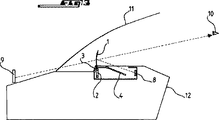
図3は、適用環境、即ち、ウインドシールド11とダッシュボード12とで図示されている自動車における、突出状態にある本発明の表示装置を示す。ヘッドアップ表示装置の動作原理によれば、光源8が生成する情報は、突出状態のプレート1に送られ、そこでは、ウインドシールド11を介して運転者10が見る、自動車の前方スペースの実像に重なる虚像9の形で、情報が表示される。
FIG. 3 shows the display device of the present invention in a protruding state in the application environment, ie the car illustrated by the windshield 11 and the
図4は、プレートが、参照番号1で示す格納位置と、参照番号1Aで示す平坦位置の両方にあるが、可動サポート2は表示位置にのみある、本発明の表示装置を示す概略側面図である。フラップ3とハッチ4は開いている。
FIG. 4 is a schematic side view showing the display device of the present invention in which the plate is in both the storage position indicated by
図4は、サポート2が、ラック14と連動するモーター付き要素13に接続して、静止位置と表示装置との間のいずれかの方向にサポート2を移動することも示している。表示位置への、移動端までの移動を微細に調整可能とするために、少なくとも二つの解決方法が考えられる。第一の解決方法は、表示位置、従って、プレート1の傾斜を微細に調整するという望ましい目標を実現するのに十分な、微細なピッチを有するラックを用いることである。この代替方式で、ラック14は、その長さの大部分が直線状であり、移動端において曲がり、これにより移動運動を、ラックの直線部に続く縦方向の構成部品と横方向の構成部品とに分割する。この場合の移動端における可動サポート2の実際の移動は、縦方向の構成部品と横方向の構成部品との間の比率に依存する。このためラックは、具体的には、間に角度を成す二つの直線区域、又は、端部において曲がっている直線部を有している。この代替の解決方法は、モーター付要素13が、移動方向に対し、横移動の自由度をもつことを明確に示唆している。
FIG. 4 also shows that the support 2 is connected to the
第二の解決方法は、例えばウォームネジなどの二次的なモーター付要素を用いて、モーター付き要素13に統合することである。この解決方法では、モーター付き要素13が、可動サポート2を静止位置から基本表示装置に向けて移動させ、次に、二次的要素が可動サポート2を微細に移動させる。
The second solution is to integrate into the
図5は、本発明の表示装置を示す斜視図である。この提示により、レール6、7がハウジング5の横方向支持壁51、52に溝の形状で効果的に埋め込まれ、プレート1は、可動サポート2のアーム23のスロット24に係合することにより、可動サポート2に取り付けられていることが分かる。
FIG. 5 is a perspective view showing a display device of the present invention. By this presentation, the rails 6, 7 are effectively embedded in the
実際、可動サポート2の移動は、レール6、7に噛み合うピン21、22を用いて誘導される。レールの配置と形状は、可動サポート2が移動する際に、サポート2の移動方向に従ってそれぞれ、平坦に又は直立して設置されるように選択される。これを実現するために、下部レール7は直線状であり、基本的に水平に設置され、これに対し、上部レール6は、可動サポート2の基本表示位置に近づくにつれて、僅かに湾曲し、角度を成して、特にレール7から更に離れるように設置される。更に、可動サポート2の上部はレール6に噛み合うピン21によって誘導され、下部はレール7に噛み合うピン52によって誘導される。
In fact, the movement of the movable support 2 is guided using
図5は、代替の実施形態において、プレート1の下端がアーム23に恒久的に位置せず、サポート2が静止位置にある時に、スロット24との噛み合いから外れることを示している。これにより、プレートが平坦状態にある時は、サポート2によるいかなるストレスも基本的にプレート1にかからないようにすることができる。可動サポート2が表示位置に向けて移動する際、プレートはスロット24と再び噛み合い、これは、プレート1が直立状態になり、プレートの重量が効果を十分に呈するようになった時に、最後に行われる。
FIG. 5 shows that in an alternative embodiment, the lower end of the
図6は、本発明の表示装置を示す上面図であり、特に、ハウジング5の横方向支持壁51、52間におけるモーター付要素13とラック14だけでなく、プレート1とサポート2の配置を示している。
FIG. 6 is a top view showing the display device of the present invention, and particularly shows the arrangement of the
図7は、本発明の表示装置を示す側面図であり、プレート1は、三つの異なる傾斜状態において、サポート2が表示位置に向けて移動している際の移動端の位置に対応している。参照番号1Bと1Cは、プレートの2番目から最後の位置、及び参照番号1で示す最終位置の前のプレートの最後の位置を、各々示す。
FIG. 7 is a side view showing the display device of the present invention, and the
図7はまた、サポート2の最終位置と、サポート2の最終位置の前の最後の位置も示す。 FIG. 7 also shows the final position of the support 2 and the last position before the final position of the support 2.
Claims (9)
表示する情報を生成する光源(8)と、
自動車のユーザに向けて情報を反映する少なくとも部分的に透明で格納式のプレート(1)を備え、
プレート(1)は静止位置と表示位置との間を移動できる可動サポート(2)に固定して取り付けられ、プレート(1)は可動サポート(2)が静止位置にあるときに格納位置をとり、可動サポート(2)が表示位置にあるときに突出位置をとり、
可動サポート(2)はレール(6,7)に移動可能に取り付けられ、
レール(6,7)は、可動サポート(2)が静止位置である水平状態と表示位置である直立状態との間を並進し、かつ枢動するように、可動サポート(2)を案内する、
表示装置。A display device for an automobile,
A light source (8) for generating information to be displayed;
An at least partially transparent and retractable plate (1) that reflects information for the user of the car,
The plate (1) is fixedly attached to a movable support (2) that can move between a stationary position and a display position, and the plate (1) takes a storage position when the movable support (2) is in the stationary position, When the movable support (2) is in the display position, take the protruding position,
The movable support (2) is movably attached to the rails (6, 7),
The rails (6, 7) guide the movable support (2) so that the movable support (2) translates and pivots between a horizontal state which is a stationary position and an upright state which is a display position.
Display device.
Applications Claiming Priority (3)
| Application Number | Priority Date | Filing Date | Title |
|---|---|---|---|
| FR0511716A FR2893553B1 (en) | 2005-11-18 | 2005-11-18 | DISPLAY DEVICE FOR A MOTOR VEHICLE AND VEHICLE COMPRISING SUCH A DEVICE |
| FR0511716 | 2005-11-18 | ||
| PCT/FR2006/051177 WO2007057608A1 (en) | 2005-11-18 | 2006-11-15 | Retractable display device for a motor vehicle and a vehicle provided therewith |
Publications (2)
| Publication Number | Publication Date |
|---|---|
| JP2009515768A JP2009515768A (en) | 2009-04-16 |
| JP5020252B2 true JP5020252B2 (en) | 2012-09-05 |
Family
ID=36678534
Family Applications (1)
| Application Number | Title | Priority Date | Filing Date |
|---|---|---|---|
| JP2008540665A Active JP5020252B2 (en) | 2005-11-18 | 2006-11-15 | Retractable vehicle display device and vehicle equipped with the device |
Country Status (11)
| Country | Link |
|---|---|
| US (1) | US7869129B2 (en) |
| EP (1) | EP1948465B1 (en) |
| JP (1) | JP5020252B2 (en) |
| CN (1) | CN101346253B (en) |
| AT (1) | ATE480420T1 (en) |
| BR (1) | BRPI0619694B1 (en) |
| DE (1) | DE602006016843D1 (en) |
| ES (1) | ES2350857T3 (en) |
| FR (1) | FR2893553B1 (en) |
| PT (1) | PT1948465E (en) |
| WO (1) | WO2007057608A1 (en) |
Cited By (5)
| Publication number | Priority date | Publication date | Assignee | Title |
|---|---|---|---|---|
| US10310263B2 (en) | 2015-06-29 | 2019-06-04 | Panasonic Intellectual Property Management Co., Ltd. | Combiner raising/lowering device and headup display device |
| US10901208B2 (en) | 2016-02-18 | 2021-01-26 | Denso Corporation | Head-up display apparatus |
| DE112016006493B4 (en) | 2016-02-25 | 2022-06-23 | Panasonic Intellectual Property Management Co., Ltd. | head-up display device |
| DE112017002738B4 (en) | 2016-05-31 | 2022-10-13 | Panasonic Intellectual Property Management Co., Ltd. | head-up display device |
| DE112017002230B4 (en) | 2016-04-28 | 2022-11-03 | Panasonic Intellectual Property Management Co., Ltd. | head-up display device |
Families Citing this family (78)
| Publication number | Priority date | Publication date | Assignee | Title |
|---|---|---|---|---|
| WO2008063632A2 (en) * | 2006-11-20 | 2008-05-29 | Johnson Controls Technology Company | Apparatus and system for providing a virtual display for a vehicle |
| JP5328766B2 (en) * | 2007-05-04 | 2013-10-30 | ジョンソン・コントロールズ・ゲー・エム・ベー・ハー | Display device |
| US7978414B2 (en) | 2007-09-28 | 2011-07-12 | Jabil Circuit, Inc. | Positioning system for a combiner in a head up display |
| US8749889B2 (en) | 2008-09-26 | 2014-06-10 | Jabil Circuit, Inc. | Head up display (HUD) system with a service position for easy display assembly replacement |
| EP2322972A1 (en) * | 2009-11-12 | 2011-05-18 | Johnson Controls Technology Company | Display device, in particular for an automobile |
| DE102009057017B4 (en) * | 2009-12-04 | 2014-08-07 | Airbus Operations Gmbh | Display for an aircraft |
| EP2529266B1 (en) * | 2010-01-27 | 2017-01-04 | Johnson Controls Technology Company | Display device, in particular for a motor vehicle |
| FR2962815B1 (en) * | 2010-07-16 | 2013-06-21 | Delphi Tech Inc | HEIGHT ADJUSTABLE HEAD DISPLAY DEVICE |
| EP2616732A1 (en) * | 2010-09-18 | 2013-07-24 | Johnson Controls GmbH | Display unit having a projection screen for a head-up display |
| KR101460959B1 (en) * | 2010-09-18 | 2014-11-13 | 존슨 컨트롤스 게엠베하 | Head-up display comprising a projection screen and a device for moving and positioning a projection screen, and method for operating such a head-up display |
| KR101544524B1 (en) * | 2010-12-16 | 2015-08-17 | 한국전자통신연구원 | Display system for augmented reality in vehicle, and method for the same |
| FR2969318B1 (en) * | 2010-12-21 | 2013-08-09 | Peugeot Citroen Automobiles Sa | HEADLESS DISPLAY DEVICE WITH TRANSPARENT BLADE WITH NON-PARALLEL FACES, FOR A VEHICLE |
| US8427751B2 (en) | 2011-01-12 | 2013-04-23 | Lite-On It Corporation | Combiner positioning system for head-up display |
| US8953247B2 (en) * | 2011-01-20 | 2015-02-10 | Lite-On Technology Corporation | Positioning system for head-up display |
| EP2541303B1 (en) | 2011-07-01 | 2017-12-20 | Johnson Controls Automotive Electronics GmbH | Head-up display for a vehicle |
| DE102011118853A1 (en) * | 2011-08-18 | 2013-02-21 | Johnson Controls Gmbh | display device |
| JP5878712B2 (en) * | 2011-09-06 | 2016-03-08 | 矢崎総業株式会社 | Vehicle display device |
| FR2983314B1 (en) | 2011-11-28 | 2014-10-10 | Delphi Tech Inc | HIGH HEAD DISPLAY DEVICE WITH REMOVABLE COMBINER |
| JP5859334B2 (en) * | 2012-02-08 | 2016-02-10 | 矢崎総業株式会社 | Head-up display device |
| GB2499793B (en) * | 2012-02-28 | 2018-01-17 | Bae Systems Plc | A deployment apparatus for a partially reflective combiner. |
| WO2013146161A1 (en) | 2012-03-29 | 2013-10-03 | 日本精機株式会社 | Combiner storage device, head-up display device |
| JP5997489B2 (en) | 2012-04-23 | 2016-09-28 | 矢崎総業株式会社 | Vehicle display device |
| JP5990399B2 (en) | 2012-05-09 | 2016-09-14 | 矢崎総業株式会社 | Vehicle display device |
| GB2504311A (en) * | 2012-07-25 | 2014-01-29 | Bae Systems Plc | Head-up display using fluidic lens |
| EP2690483A1 (en) * | 2012-07-25 | 2014-01-29 | Johnson Controls Automotive Electronics SAS | Head-up display and method for operating it |
| FR2994284B1 (en) * | 2012-08-06 | 2015-07-17 | Johnson Contr Automotive Elect | DISPLAY DEVICE, IN PARTICULAR FOR A MOTOR VEHICLE |
| JP6108874B2 (en) * | 2013-02-27 | 2017-04-05 | 矢崎総業株式会社 | Vehicle display device |
| EP2784570B1 (en) | 2013-03-27 | 2018-01-17 | Jabil Inc. | Head-up display system |
| JP6114380B2 (en) * | 2013-04-01 | 2017-04-12 | パイオニア株式会社 | Display system |
| JP5990485B2 (en) | 2013-04-02 | 2016-09-14 | 矢崎総業株式会社 | Vehicle display device |
| WO2014162512A1 (en) * | 2013-04-02 | 2014-10-09 | パイオニア株式会社 | Rack and spur gear mechanism, rack and spur gear drive mechanism and rack and drive device |
| KR20140134184A (en) * | 2013-05-13 | 2014-11-21 | 삼성디스플레이 주식회사 | Head-up display system and method and apparatus for controlling the same |
| JP6313933B2 (en) * | 2013-06-03 | 2018-04-18 | 矢崎総業株式会社 | Head-up display device |
| FR3007852B1 (en) * | 2013-06-28 | 2016-12-23 | Valeo Etudes Electroniques | DISPLAY, INCLUDING HIGH HEAD DISPLAY, ESPECIALLY FOR MOTOR VEHICLE |
| JP6265701B2 (en) | 2013-11-22 | 2018-01-24 | 株式会社デンソーテン | Head-up display device |
| CN103770721B (en) * | 2014-01-03 | 2017-01-25 | 惠州市华阳多媒体电子有限公司 | Automobile display device and automobile |
| CN104914574B (en) * | 2014-03-11 | 2018-12-14 | 鸿富锦精密工业(深圳)有限公司 | Head-up display device |
| CN103885183B (en) * | 2014-03-12 | 2017-01-04 | 惠州市华阳多媒体电子有限公司 | Callable vehicle-mounted head-up display and vehicle |
| WO2015150569A1 (en) * | 2014-04-03 | 2015-10-08 | Johnson Controls Automotive Electronics Sas | Display device, in particular for a motor vehicle |
| EP2930048A1 (en) * | 2014-04-10 | 2015-10-14 | Johnson Controls Automotive Electronics SAS | Head up display projecting visual information onto a screen |
| FR3020689B1 (en) * | 2014-04-30 | 2017-10-13 | Johnson Controls Automotive Electronics Sas | DISPLAY DEVICE, IN PARTICULAR FOR A MOTOR VEHICLE |
| DE102014106498A1 (en) * | 2014-05-08 | 2015-11-12 | Valeo Schalter Und Sensoren Gmbh | Display device for a motor vehicle, motor vehicle and method for operating a display device |
| JP6267583B2 (en) * | 2014-05-16 | 2018-01-24 | ミネベアミツミ株式会社 | Tilt mechanism and display device having the same |
| FR3021417B1 (en) * | 2014-05-20 | 2017-10-06 | Peugeot Citroen Automobiles Sa | DISPLAY DEVICE |
| JP6274040B2 (en) * | 2014-07-18 | 2018-02-07 | 株式会社デンソー | Display device |
| US9405120B2 (en) | 2014-11-19 | 2016-08-02 | Magna Electronics Solutions Gmbh | Head-up display and vehicle using the same |
| CN104590147B (en) * | 2014-12-25 | 2018-01-26 | 惠州市华阳多媒体电子有限公司 | A kind of reflective viewing screen double track jack of HUD |
| EP3307590B1 (en) | 2015-06-11 | 2019-08-07 | Bosch Car Multimedia Portugal, S.A. | Kinematic mechanism for a head-up display |
| WO2017010530A1 (en) * | 2015-07-14 | 2017-01-19 | パイオニア株式会社 | Display device |
| JP6452819B2 (en) * | 2015-07-14 | 2019-01-16 | パイオニア株式会社 | Display device |
| DE102015111617A1 (en) | 2015-07-17 | 2017-01-19 | Valeo Schalter Und Sensoren Gmbh | Display device for a motor vehicle with a gearing having guideway and motor vehicle |
| DE102015111619A1 (en) | 2015-07-17 | 2017-01-19 | Valeo Schalter Und Sensoren Gmbh | Display device for a motor vehicle with spring element and motor vehicle |
| WO2017014132A1 (en) * | 2015-07-17 | 2017-01-26 | パイオニア株式会社 | Display device |
| DE102015111618B4 (en) | 2015-07-17 | 2020-11-26 | Valeo Schalter Und Sensoren Gmbh | Display device for a motor vehicle with overload protection and a motor vehicle |
| JP6620925B2 (en) * | 2015-07-23 | 2019-12-18 | パナソニックIpマネジメント株式会社 | Head-up display device |
| CN105022221B (en) * | 2015-08-18 | 2017-07-04 | 上海创功通讯技术有限公司 | Smart projector |
| DE102015013340A1 (en) | 2015-10-14 | 2017-04-20 | Audi Ag | Cover system and housing with the lid system |
| WO2017069039A1 (en) * | 2015-10-23 | 2017-04-27 | 日本精機株式会社 | Head-up display apparatus |
| US10302953B2 (en) | 2015-12-11 | 2019-05-28 | Volvo Truck Corporation | Adjustable head-up display arrangement for a vehicle |
| JP6643915B2 (en) * | 2016-02-17 | 2020-02-12 | 矢崎総業株式会社 | Display system for vehicles |
| JP6556643B2 (en) * | 2016-02-19 | 2019-08-07 | ヒュンダイ・モービス・カンパニー・リミテッド | Head-up display device |
| JP6608330B2 (en) * | 2016-04-22 | 2019-11-20 | ヒュンダイ・モービス・カンパニー・リミテッド | Head-up display device |
| FR3051051B1 (en) * | 2016-05-03 | 2020-06-05 | Valeo Comfort And Driving Assistance | IMAGE PROJECTION DEVICE FOR HIGH HEAD DISPLAY WITH TWO-PART PROTECTION SHUTTER AND RELATED HIGH HEAD DISPLAY |
| FR3051052B1 (en) * | 2016-05-03 | 2021-01-01 | Valeo Comfort & Driving Assistance | IMAGE PROJECTION DEVICE FOR HEAD-UP DISPLAY WITH ASSOCIATED PROTECTIVE SHUTTER AND HEAD-UP DISPLAY |
| CN107870421A (en) * | 2016-09-27 | 2018-04-03 | 上海蔚兰动力科技有限公司 | The adjustable reflector of head-up display device and include its head-up display device |
| DE102016122420A1 (en) * | 2016-11-22 | 2018-05-24 | Valeo Schalter Und Sensoren Gmbh | Head-up display device for a motor vehicle with an adjusting device, driver assistance system, motor vehicle and method for adjusting the head-up display device |
| FR3060139B1 (en) * | 2016-12-08 | 2019-07-26 | Alstom Transport Technologies | METHOD OF OPTIMIZING THE POSITIONING OF A HIGH HEAD DISPLAY |
| FR3063818B1 (en) * | 2017-03-09 | 2019-04-19 | Visteon Global Technologies, Inc. | HIGH HEAD DISPLAY DEVICE |
| FR3068317B1 (en) * | 2017-07-03 | 2019-07-19 | Psa Automobiles Sa | LIGHTING AND / OR LIGHT SIGNALING DEVICE COMPRISING A RETRACTABLE DISPLAY SYSTEM |
| US10625688B2 (en) * | 2017-11-06 | 2020-04-21 | Global Ip Holdings, Llc | Assembly capable of deploying an electronic device having a display screen in a vehicle |
| US10884104B2 (en) | 2017-12-20 | 2021-01-05 | Ecolink Intelligent Technology, Inc. | Monitoring device having 360 degree sensing capabilities |
| JP7023580B2 (en) * | 2018-05-22 | 2022-02-22 | アルパイン株式会社 | Guidance drive device |
| JP7234423B2 (en) * | 2018-05-22 | 2023-03-07 | アルパイン株式会社 | Display device using guide drive |
| US20190369382A1 (en) * | 2018-06-01 | 2019-12-05 | E-Lead Electronic Co., Ltd. | Magnifying display screen device |
| WO2020122453A1 (en) * | 2018-12-13 | 2020-06-18 | 엘지전자 주식회사 | Display device for vehicle |
| CN109720278B (en) * | 2018-12-20 | 2021-06-15 | 西安理工大学 | Automobile navigation information head-up display capable of automatically lifting |
| GB2597923A (en) * | 2020-07-31 | 2022-02-16 | Continental Automotive Gmbh | A backlight unit for a vehicle component |
| KR20220099295A (en) * | 2021-01-06 | 2022-07-13 | 현대자동차주식회사 | Apparatus for Opening of the Display unit |
Family Cites Families (13)
| Publication number | Priority date | Publication date | Assignee | Title |
|---|---|---|---|---|
| US4664475A (en) * | 1985-08-14 | 1987-05-12 | Hughes Aircraft Company | Combiner mounting and stowage mechanism |
| US5394203A (en) * | 1994-06-06 | 1995-02-28 | Delco Electronics Corporation | Retracting head up display with image position adjustment |
| US5457575A (en) * | 1994-06-20 | 1995-10-10 | Delco Electronics Corporation | Retracting head up display with fine adjustment of combiner |
| JP3621479B2 (en) * | 1995-09-27 | 2005-02-16 | カルソニックカンセイ株式会社 | Head-up display device |
| US5905477A (en) * | 1996-08-12 | 1999-05-18 | Shimadzu Corporation | Head-up display having installation mechanism |
| JPH10203199A (en) * | 1997-01-17 | 1998-08-04 | Nissan Motor Co Ltd | Display unit for vehicle |
| JPH11281916A (en) * | 1998-03-30 | 1999-10-15 | Asahi Glass Co Ltd | Information display device |
| JP3803488B2 (en) * | 1998-05-25 | 2006-08-02 | 日本発条株式会社 | Support device for display device |
| JP4541510B2 (en) * | 2000-08-08 | 2010-09-08 | 富士重工業株式会社 | Retractable display device |
| JP4387608B2 (en) * | 2001-03-30 | 2009-12-16 | 矢崎総業株式会社 | Support device for combiner for vehicle display system |
| JP4611566B2 (en) * | 2001-05-11 | 2011-01-12 | 矢崎総業株式会社 | Head-up display combiner storage method and head-up display combiner storage device |
| US6808274B2 (en) * | 2002-06-04 | 2004-10-26 | Raytheon Company | Method and system for deploying a mirror assembly from a recessed position |
| JP4351565B2 (en) * | 2003-07-29 | 2009-10-28 | 矢崎総業株式会社 | Head-up display device |
-
2005
- 2005-11-18 FR FR0511716A patent/FR2893553B1/en not_active Expired - Fee Related
-
2006
- 2006-11-15 ES ES06831339T patent/ES2350857T3/en active Active
- 2006-11-15 DE DE602006016843T patent/DE602006016843D1/en active Active
- 2006-11-15 PT PT06831339T patent/PT1948465E/en unknown
- 2006-11-15 EP EP06831339A patent/EP1948465B1/en active Active
- 2006-11-15 WO PCT/FR2006/051177 patent/WO2007057608A1/en active Application Filing
- 2006-11-15 JP JP2008540665A patent/JP5020252B2/en active Active
- 2006-11-15 BR BRPI0619694-2A patent/BRPI0619694B1/en active IP Right Grant
- 2006-11-15 CN CN2006800428041A patent/CN101346253B/en active Active
- 2006-11-15 US US12/094,162 patent/US7869129B2/en active Active
- 2006-11-15 AT AT06831339T patent/ATE480420T1/en not_active IP Right Cessation
Cited By (6)
| Publication number | Priority date | Publication date | Assignee | Title |
|---|---|---|---|---|
| US10310263B2 (en) | 2015-06-29 | 2019-06-04 | Panasonic Intellectual Property Management Co., Ltd. | Combiner raising/lowering device and headup display device |
| DE112016002933B4 (en) | 2015-06-29 | 2022-06-09 | Panasonic Intellectual Property Management Co., Ltd. | Combinator raising/lowering device and head-up display device |
| US10901208B2 (en) | 2016-02-18 | 2021-01-26 | Denso Corporation | Head-up display apparatus |
| DE112016006493B4 (en) | 2016-02-25 | 2022-06-23 | Panasonic Intellectual Property Management Co., Ltd. | head-up display device |
| DE112017002230B4 (en) | 2016-04-28 | 2022-11-03 | Panasonic Intellectual Property Management Co., Ltd. | head-up display device |
| DE112017002738B4 (en) | 2016-05-31 | 2022-10-13 | Panasonic Intellectual Property Management Co., Ltd. | head-up display device |
Also Published As
| Publication number | Publication date |
|---|---|
| BRPI0619694B1 (en) | 2019-08-20 |
| WO2007057608A1 (en) | 2007-05-24 |
| CN101346253A (en) | 2009-01-14 |
| US7869129B2 (en) | 2011-01-11 |
| US20080285138A1 (en) | 2008-11-20 |
| DE602006016843D1 (en) | 2010-10-21 |
| ATE480420T1 (en) | 2010-09-15 |
| JP2009515768A (en) | 2009-04-16 |
| FR2893553B1 (en) | 2009-07-03 |
| PT1948465E (en) | 2010-10-21 |
| ES2350857T3 (en) | 2011-01-27 |
| EP1948465B1 (en) | 2010-09-08 |
| EP1948465A1 (en) | 2008-07-30 |
| FR2893553A1 (en) | 2007-05-25 |
| BRPI0619694A2 (en) | 2011-10-11 |
| CN101346253B (en) | 2013-06-19 |
Similar Documents
| Publication | Publication Date | Title |
|---|---|---|
| JP5020252B2 (en) | Retractable vehicle display device and vehicle equipped with the device | |
| JP6114380B2 (en) | Display system | |
| US20140320382A1 (en) | Head-up display device with retractable combiner | |
| US9063327B2 (en) | Adjustable head-up display device | |
| JP4648730B2 (en) | Vehicle display device | |
| US5394203A (en) | Retracting head up display with image position adjustment | |
| CN101578547B (en) | Apparatus and system for providing virtual display for vehicle | |
| JP4790708B2 (en) | Display device | |
| JP5878712B2 (en) | Vehicle display device | |
| JP4351565B2 (en) | Head-up display device | |
| CN105182531B (en) | The head-up display system of synthesizer is moved with driving mechanism | |
| JP6575855B2 (en) | In-vehicle combiner lifting device and in-vehicle head-up display device | |
| JP4404738B2 (en) | Head-up display device | |
| TWI639521B (en) | Head up display | |
| JP4223942B2 (en) | Head-up display device | |
| EP3064391B1 (en) | Head-up display system with rotation drive means arranged parallel to a combiner to move the combiner | |
| JP4263658B2 (en) | Head-up display device and mirror unit used therefor | |
| JP2006069473A (en) | Head-up display | |
| JP2016210266A (en) | Panel opening/closing device | |
| JP2006065092A (en) | Head-up display | |
| WO2017145732A1 (en) | Storage device | |
| JP2017142513A (en) | Display system | |
| EP3634802A1 (en) | Combiner mirror positioning system for a heads-up display | |
| JP2019003031A (en) | Upper-contact electric reflection piece device |
Legal Events
| Date | Code | Title | Description |
|---|---|---|---|
| A621 | Written request for application examination |
Free format text: JAPANESE INTERMEDIATE CODE: A621 Effective date: 20091027 |
|
| A131 | Notification of reasons for refusal |
Free format text: JAPANESE INTERMEDIATE CODE: A131 Effective date: 20110215 |
|
| A601 | Written request for extension of time |
Free format text: JAPANESE INTERMEDIATE CODE: A601 Effective date: 20110510 |
|
| A602 | Written permission of extension of time |
Free format text: JAPANESE INTERMEDIATE CODE: A602 Effective date: 20110517 |
|
| A521 | Request for written amendment filed |
Free format text: JAPANESE INTERMEDIATE CODE: A523 Effective date: 20110525 |
|
| A131 | Notification of reasons for refusal |
Free format text: JAPANESE INTERMEDIATE CODE: A131 Effective date: 20111206 |
|
| A521 | Request for written amendment filed |
Free format text: JAPANESE INTERMEDIATE CODE: A523 Effective date: 20111209 |
|
| TRDD | Decision of grant or rejection written | ||
| A01 | Written decision to grant a patent or to grant a registration (utility model) |
Free format text: JAPANESE INTERMEDIATE CODE: A01 Effective date: 20120515 |
|
| A01 | Written decision to grant a patent or to grant a registration (utility model) |
Free format text: JAPANESE INTERMEDIATE CODE: A01 |
|
| A61 | First payment of annual fees (during grant procedure) |
Free format text: JAPANESE INTERMEDIATE CODE: A61 Effective date: 20120612 |
|
| R150 | Certificate of patent or registration of utility model |
Ref document number: 5020252 Country of ref document: JP Free format text: JAPANESE INTERMEDIATE CODE: R150 Free format text: JAPANESE INTERMEDIATE CODE: R150 |
|
| FPAY | Renewal fee payment (event date is renewal date of database) |
Free format text: PAYMENT UNTIL: 20150622 Year of fee payment: 3 |
|
| R250 | Receipt of annual fees |
Free format text: JAPANESE INTERMEDIATE CODE: R250 |
|
| R250 | Receipt of annual fees |
Free format text: JAPANESE INTERMEDIATE CODE: R250 |
|
| R250 | Receipt of annual fees |
Free format text: JAPANESE INTERMEDIATE CODE: R250 |
|
| R250 | Receipt of annual fees |
Free format text: JAPANESE INTERMEDIATE CODE: R250 |
|
| R250 | Receipt of annual fees |
Free format text: JAPANESE INTERMEDIATE CODE: R250 |
|
| R250 | Receipt of annual fees |
Free format text: JAPANESE INTERMEDIATE CODE: R250 |
|
| R250 | Receipt of annual fees |
Free format text: JAPANESE INTERMEDIATE CODE: R250 |
|
| R250 | Receipt of annual fees |
Free format text: JAPANESE INTERMEDIATE CODE: R250 |
|
| R250 | Receipt of annual fees |
Free format text: JAPANESE INTERMEDIATE CODE: R250 |
|
| R250 | Receipt of annual fees |
Free format text: JAPANESE INTERMEDIATE CODE: R250 |