WO2018008155A1 - 健康モニタリングシステム、健康モニタリング方法および健康モニタリングプログラム - Google Patents
健康モニタリングシステム、健康モニタリング方法および健康モニタリングプログラム Download PDFInfo
- Publication number
- WO2018008155A1 WO2018008155A1 PCT/JP2016/070338 JP2016070338W WO2018008155A1 WO 2018008155 A1 WO2018008155 A1 WO 2018008155A1 JP 2016070338 W JP2016070338 W JP 2016070338W WO 2018008155 A1 WO2018008155 A1 WO 2018008155A1
- Authority
- WO
- WIPO (PCT)
- Prior art keywords
- information
- unit
- user
- measurement
- health monitoring
- Prior art date
Links
Images


Classifications
-
- G—PHYSICS
- G01—MEASURING; TESTING
- G01N—INVESTIGATING OR ANALYSING MATERIALS BY DETERMINING THEIR CHEMICAL OR PHYSICAL PROPERTIES
- G01N33/00—Investigating or analysing materials by specific methods not covered by groups G01N1/00 - G01N31/00
- G01N33/48—Biological material, e.g. blood, urine; Haemocytometers
- G01N33/483—Physical analysis of biological material
- G01N33/487—Physical analysis of biological material of liquid biological material
- G01N33/493—Physical analysis of biological material of liquid biological material urine
-
- A—HUMAN NECESSITIES
- A61—MEDICAL OR VETERINARY SCIENCE; HYGIENE
- A61B—DIAGNOSIS; SURGERY; IDENTIFICATION
- A61B5/00—Measuring for diagnostic purposes; Identification of persons
- A61B5/20—Measuring for diagnostic purposes; Identification of persons for measuring urological functions restricted to the evaluation of the urinary system
- A61B5/207—Sensing devices adapted to collect urine
- A61B5/208—Sensing devices adapted to collect urine adapted to determine urine quantity, e.g. flow, volume
-
- A—HUMAN NECESSITIES
- A61—MEDICAL OR VETERINARY SCIENCE; HYGIENE
- A61B—DIAGNOSIS; SURGERY; IDENTIFICATION
- A61B5/00—Measuring for diagnostic purposes; Identification of persons
- A61B5/68—Arrangements of detecting, measuring or recording means, e.g. sensors, in relation to patient
- A61B5/6887—Arrangements of detecting, measuring or recording means, e.g. sensors, in relation to patient mounted on external non-worn devices, e.g. non-medical devices
-
- G—PHYSICS
- G01—MEASURING; TESTING
- G01N—INVESTIGATING OR ANALYSING MATERIALS BY DETERMINING THEIR CHEMICAL OR PHYSICAL PROPERTIES
- G01N1/00—Sampling; Preparing specimens for investigation
- G01N1/02—Devices for withdrawing samples
- G01N1/10—Devices for withdrawing samples in the liquid or fluent state
-
- G—PHYSICS
- G01—MEASURING; TESTING
- G01N—INVESTIGATING OR ANALYSING MATERIALS BY DETERMINING THEIR CHEMICAL OR PHYSICAL PROPERTIES
- G01N33/00—Investigating or analysing materials by specific methods not covered by groups G01N1/00 - G01N31/00
- G01N33/48—Biological material, e.g. blood, urine; Haemocytometers
-
- A—HUMAN NECESSITIES
- A61—MEDICAL OR VETERINARY SCIENCE; HYGIENE
- A61B—DIAGNOSIS; SURGERY; IDENTIFICATION
- A61B10/00—Other methods or instruments for diagnosis, e.g. instruments for taking a cell sample, for biopsy, for vaccination diagnosis; Sex determination; Ovulation-period determination; Throat striking implements
- A61B10/0045—Devices for taking samples of body liquids
- A61B10/007—Devices for taking samples of body liquids for taking urine samples
-
- E—FIXED CONSTRUCTIONS
- E03—WATER SUPPLY; SEWERAGE
- E03D—WATER-CLOSETS OR URINALS WITH FLUSHING DEVICES; FLUSHING VALVES THEREFOR
- E03D9/00—Sanitary or other accessories for lavatories ; Devices for cleaning or disinfecting the toilet room or the toilet bowl; Devices for eliminating smells
Definitions
- the present invention relates to a health monitoring system, a health monitoring method, and a health monitoring program, and more particularly to a health monitoring system, a health monitoring method, and a health monitoring program that are installed in a toilet and analyze urination to estimate a disease.
- Patent Document 1 discloses that the concentration of a specific component in one urine of a human being measured and the concentration of the specific component in the whole urine of one day measured.
- the data representing the correlation between the data is stored, and using the correlation, the concentration of the specific component in the whole urine of the subject is calculated and obtained, and the subject's concentration is calculated from the obtained concentration.
- a urination information measuring device for calculating the amount of excretion of a specific component in the whole urine of a day is disclosed.
- Patent Document 2 discloses a urination information measuring device for calculating urine output and urine flow rate by a bowl of a toilet bowl for storing urine and urine data measuring means for measuring the volume and weight of urine stored in the bowl. It is disclosed.
- the urination measuring device described in Patent Document 2 calculates a urination amount and a urine flow rate based on each water level or a water level change rate at the start of urination or at the end of urination, and applies a predetermined vibration model to the calculated data.
- the urination information is calculated by processing according to the above.
- Patent Document 1 it is largely composed of a housing and a sensor unit, and the housing must be sprinkled with the urine excreted by the subject to be measured by holding the housing with the hand of the subject. Convenience was not always sufficient.
- the present invention has an object to provide a simple and easy-to-use health monitoring system, health monitoring method, and health monitoring program for analyzing urination such as urine component analysis and estimating a disease based on the analysis result. .
- the health monitoring system analyzes a fluid model obtained by modeling a fluid flowing region based on the fluid information and a measuring unit that measures fluid information regarding the fluid in the stored water into which the urine of the toilet user flows.
- An analysis unit that analyzes urination and an estimation unit that estimates a user's disease based on urination information of urination, and the measurement unit is colored according to the components of the stored water into which urine flows. It includes a cartridge for storing a changing film, and each time the fluid information is measured, the film used for the measurement is pushed out from the cartridge.
- the measurement unit may include an extrusion mechanism that pushes out a film used for measurement out of the plurality of films stacked and stored in the cartridge.
- the measurement unit further includes an arm having a holding unit for holding the film pushed out from the cartridge, and the film held by the holding unit by operating the arm. May be immersed in the stored water into which the user's urine flows.
- the measurement unit further includes a rotation mechanism that is rotatably connected to one end of the arm, and is provided at the other end of the arm by rotating the arm by the rotation mechanism. You may move a clamping part to the position immersed in the stored water into which the user's urine flowed.
- the health monitoring system includes a photographing unit including a photographing unit that photographs film and generates photographing information, and the measurement unit operates the arm so that the urine of the user flows into the stored water.
- the film immersed in the film may be moved to a position where the photographing unit can photograph the film.
- the cartridge is detachable from the measurement unit, and when the film stored in the cartridge disappears in the measurement unit, the cartridge stores a plurality of films. It may be replaceable with a new cartridge.
- the health monitoring system includes a storage unit that stores bowl shape information for each toilet and water volume information, and the fluid information is at least one of the stored water into which the stored water or urine flows.
- Water temperature information generated by measuring two water temperatures may be included, and the analysis unit may analyze urination based on at least one of shape information and water amount information in addition to fluid information.
- the health monitoring system generates voltage information by measuring the potential difference between the two electrodes immersed in the pooled water or the pooled urine, and urination information including the water volume information and the urine volume of urination
- a correction unit that corrects the voltage information and an analysis unit that analyzes the urine component based on the corrected voltage information may be provided.
- the measurement unit when the measurement unit reaches at least one of the water temperature information and the voltage information reaches a predetermined threshold, at least one of the water temperature or the potential difference of the stored water into which urine flows.
- One measurement may start or end.
- the estimation unit creates a feature vector from the imaging information, identifies the created feature vector by training data, and estimates a disease based on the identified feature vector. Also good.
- the health monitoring system further includes a user identification unit for identifying a user based on user identification information output from a terminal or IC card owned by the user, and the estimation unit is a result of the identification. Based on the above, the disease may be estimated for each user.
- the health monitoring system further includes a measurement unit that measures the weight of the user received by the toilet seat of the toilet bowl when the user uses the toilet seat and generates weight information, and the weight The user may be identified based on the information.
- a health monitoring system method includes a measuring step for measuring fluid information regarding fluid in the stored water into which urination of a toilet user flows, and a fluid model obtained by modeling a region where the fluid flows based on the fluid information. Analyzing step to analyze urination by analysis, guessing step to guess the user's disease based on urination information of urination, and every time fluid information is measured, according to the component of the accumulated water into which urine flows An extrusion step of extruding the film used for the measurement from a cartridge containing the color-changing film.
- the health monitoring program is a program for controlling a computer, and a fluid flows based on a measurement function for measuring fluid information related to fluid in the stored water into which the urine of a toilet user has flowed and fluid information.
- An analysis function that analyzes urination by analyzing a fluid model that models the area, an estimation function that estimates the user's disease based on urination information of urination, and urination flows every time fluid information is measured
- An extrusion function of pushing out the film used for the measurement from a cartridge storing a film whose color changes according to the component of the accumulated water is realized by a computer.
- the health monitoring system analyzes a fluid model obtained by modeling a fluid flowing region based on the fluid information and a measuring unit that measures fluid information regarding the fluid in the stored water into which the urine of the toilet user flows.
- an analysis unit that analyzes urination and an estimation unit that estimates a user's disease based on urination information of urination are provided.
- the urine component can be measured simply by installing the health monitoring system according to the present invention in the existing toilet bowl, and the subject can measure the urine component simply by excreting as usual. Therefore, the measurement can be performed more simply and hygienically than the measurement, and the usability can be improved.
- the health monitoring system and the health monitoring method according to the present invention analyze the movement of fluid by fluid simulation and analyze the amount of urine, it is possible to consider how much the urination is diluted by the stored water. Can be analyzed accurately.
- the health monitoring system and health monitoring method according to the present invention can improve simplicity and usability in analyzing urination information and estimating disease.
- FIG. 2 is a system diagram illustrating an example of a configuration of a health monitoring system 500.
- FIG. 2 is a block diagram illustrating a configuration example of a health monitoring system 500.
- FIG. It is a block diagram which shows the other structural example of the health monitoring system.
- 1 is a diagram schematically illustrating an example of an overview of a health monitoring system 500.
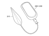
- FIG. It is a figure which shows typically an example of the general appearance of the measuring apparatus 200 of the health monitoring system 500.
- 3 is a diagram schematically illustrating an example of an internal structure of a measurement unit 210 included in the measurement apparatus 200.
- FIG. FIG. 6 is a diagram schematically illustrating another example of the internal structure of the measurement unit 210 included in the measurement apparatus 200.
- FIG 3 is a diagram schematically illustrating a configuration example of a measurement unit 210 included in the measurement apparatus 200. It is a figure which shows typically a mode that the clamping part 41 of the arm 40 moves to an up-down direction. It is a figure which shows typically an example of the structure of the film 90 which comprises the imaging
- FIG. 3 is a diagram schematically illustrating a configuration example of a measurement unit 210 included in the measurement apparatus 200. It is a schematic diagram which shows the usage condition of the measurement part. It is a figure which shows the structural example of the toilet bowl to which the pressure sensor 800 was attached.
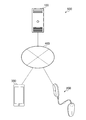
- FIG. 1 is a system diagram showing an example of a health monitoring system configuration according to the first embodiment of the present invention.
- the system includes a server 100, a measuring apparatus 200, and a user terminal 300.
- Server 100 is connected to measurement device 200 and user terminal 300 via network 400.
- the specific device of the user terminal 300 is not limited to a smartphone as illustrated, and may be a mobile terminal, a tablet terminal, a personal computer, or other electronic devices, for example.
- the user terminal 300 may be, for example, a computer (eg, desktop, laptop, tablet, etc.), a media computer platform (eg, cable, satellite set-top box, digital video recorder), a handheld computer device (eg, PDA (personal digital assistant) , E-mail clients, etc.), mobile phones (eg, smartphones, feature phones, etc.), wearable terminals (glasses-type devices, watch-type devices, etc.) or other types of computers, or communication platforms, but the invention is not limited thereto. It is not something.
- the system may use a cloud service (including both public cloud and private cloud), or may provide a service by physically providing a shared or dedicated server in the target facility.
- the user terminal 300 is equipped with an application (hereinafter referred to as a “health monitoring app”) that displays health status monitoring results (including analysis results and estimation results) that are part of the health monitoring system according to the first embodiment of the present invention. As shown in FIG. 3, it is possible to check the health status of the user by viewing the display of the health monitoring application.
- a health monitoring app an application that displays health status monitoring results (including analysis results and estimation results) that are part of the health monitoring system according to the first embodiment of the present invention. As shown in FIG. 3, it is possible to check the health status of the user by viewing the display of the health monitoring application.
- the health monitoring system 500 installs a measuring device 200 in an existing toilet or the like, and measures fluid information regarding the fluid in the stored water into which the urine of the user of the toilet flows into the measuring device 200. Then, based on the fluid information measured in the server 100, the urination is analyzed by analyzing a fluid model obtained by modeling the region in which the fluid flows. Based on the urination information of the analyzed urination, the disease of the user Can be guessed. As a result, the health monitoring 500 is simple and easy to use, for example, while at home or at work, and because the user can determine that it is a sign of illness or illness by simply performing normal urination. Good health monitoring service with good sustainability.
- the health monitoring system 500 is not limited to application to homes and workplaces, but can be used for patient health management in nursing homes and hospitals, and can reduce risk on the management side.
- “urination information” refers to various types of information related to urination of the user, and may include urine volume, urine temperature, urine components, and the like.
- the health monitoring system 500 may be configured by the measurement device 200 alone or the measurement device 200 and the user terminal 300. Good.
- a service using a cloud service is shown.
- a cloud doctor service using artificial intelligence for example, by machine learning using deep learning or the like
- a physical condition medical service for example, a patient's health status over a network
- a cloud mother service for example, a service for monitoring a child's health and physical condition over a network.
- FIG. 2 is a block diagram illustrating a configuration example of the health monitoring system according to the first embodiment of the present invention.
- the health monitoring system includes a measurement device 200 including a measurement unit 210 and a server 100 including a control unit including an analysis unit 121 and an estimation unit 124.
- the measuring unit 210 of the measuring apparatus 200 measures fluid information regarding the fluid in the stored water into which the urine of the toilet user has flowed.
- the analysis unit 121 of the server 100 analyzes urination by analyzing a fluid model obtained by modeling a fluid based on the fluid information measured by the measurement unit 120. Moreover, the estimation part 124 of the server 100 estimates a user's disease based on the urination information of urination.
- the measurement part 210 contains the cartridge which stores the film which changes a color according to the component of the stored water into which the urine flowed in, and from the said cartridge whenever it measures the said fluid information.
- the film used for the measurement is extruded.
- the measurement unit 210 includes a cartridge storing a film used for measuring fluid information, and pushes the film used for measurement from the cartridge each time the fluid information is measured.
- Urine components can be measured without the hassle of preparing a film. Therefore, the person to be measured can perform measurement more simply and hygienically than, for example, by sprinkling urine on the apparatus, and usability can be improved.
- FIG. 3 is a block diagram illustrating an example of functional configurations of the server 100, the measurement apparatus 200, and the user terminal 300.
- positioning of each part you may change suitably between the server 100, the measuring apparatus 200, and the user terminal 300 according to the operating environment, the condition, etc. of each apparatus.
- the analysis unit 121, the correction unit 122, the analysis unit 123, and the estimation unit 124 of the server 100 may be arranged in the control unit 230 of the measurement apparatus 200 or may be arranged in the control unit 320 of the user terminal 200.
- the server 100 includes a communication unit 110, a control unit 120, and a storage unit 130.
- the server 100 can be configured in a multi-stage configuration.
- the server 100 may be configured by a server (relay server) installed in a facility and a server that includes a specific area including a plurality of facilities or all areas.
- a server As the transmission timing of the relay server, (1) periodically (for example, every fixed time determined in consideration of the capacity of the storage unit 130), (3) a threshold is set for the storage capacity of the storage unit 250. The timing when the threshold is reached may be used as the transmission timing.
- the communication unit 110 includes a reception unit 111 and a transmission unit 112, and has a function of executing communication with the measurement apparatus 200 and the user terminal 300 via the network 400.
- the communication may be either wired or wireless, and any communication protocol may be used as long as mutual communication can be performed.
- the network 400 includes, for example, LTE (Long Term Evolution), LANs (Local Area Networks), WANs (Wide Area Network), MANs (Metropolitan Area Networks), and ISDNs (IntelliNetworks). (Code Division Multiple Access), Bluetooth (registered trademark), satellite communication, and other networks, regardless of whether wired or wireless, the information processing apparatus 100 or the information processing terminal 200 can communicate with each other. Any network may be used.
- the receiving unit 111 has a function of receiving measurement data and the like from each measuring device 200 and each user terminal 300 via the network 400 according to the control of the control unit 120 and transmitting the measurement data to the control unit 120.
- the receiver 111 stores the water temperature information of the water in the bowl of the toilet bowl from the measuring device 200 and the water containing the urine of the user of the toilet bowl (hereinafter referred to as “urine-containing water”).
- Electrode is immersed in urine-containing water, voltage information based on the potential difference between the electrodes, user identification information for identifying the user, illuminance information, and photographing information obtained by photographing the film 90 reacted with the reagent in the photographing unit 212 (hereinafter referred to as “photographing information”). Is transmitted to the control unit 120.
- the transmission unit 112 has a function of transmitting control data and the like to each measuring device 200 and monitoring result data and the like to each user terminal 300 through the network 400 according to the control of the control unit 120.
- the transmission unit 112 includes user information (for example, ID information) stored in the storage unit 130 for control of the user identification unit 220, measurement and photographing of the measurement unit 210, and user identification unit 220.
- Dynamic parameter data and the like necessary for identification are transmitted to the measuring apparatus 200, and display data representing monitoring results such as analysis results related to the analyzed urine component, estimation results related to the positive and negative of the estimated disease, etc. It transmits to the user terminal 300.
- the control unit 120 is a processor that includes an analysis unit 121, a correction unit 122, an analysis unit 123, and an estimation unit 124, and has a function of controlling each unit of the server 100. Further, when the analysis result is transmitted from the analysis unit 123 or when the estimation result is transmitted from the estimation unit 124, the control unit 120 displays the text, a table, or a graph on the display unit 330 of the user terminal 300. Generate display data. The control unit 120 transmits the generated display data to the transmission unit 112 for transmission to the user terminal 300.
- the analysis unit 121 has a function of analyzing urination by analyzing a fluid model obtained by modeling a region where the fluid flows based on the fluid information.
- fluid information refers to information necessary for fluid analysis, and is composed of toilet bowl shape information (hereinafter referred to as “shape information”), information on the amount of water stored in the toilet bowl, water temperature information, and the like. Is done.
- the analysis unit 121 flows around the measurement unit 210 based on at least one of, for example, the shape information of the toilet bowl, the amount of water stored in the toilet bowl, or the water temperature information. Based on the fluid model obtained by modeling the fluid, urination is analyzed by analyzing the fluid around the measurement unit 210 and calculating the amount of urine. In addition to the toilet bowl shape information, the amount of stored water in the toilet bowl, and the water temperature information, the analysis unit 121 includes at least information on the toilet environment such as the amount information of the detergent or the component information of the detergent. By adding any one of them, the urination information may be analyzed by modeling the fluid based on these. This eliminates the need to collect urine alone to measure urine volume, or to measure urine volume from the rate of change in water level using a measuring instrument attached to a toilet bowl or drainage pipe. A health monitoring system can be provided.
- the modeling of the fluid is based on the water temperature information generated from the measured temperature of the stored water and urine-containing water using, for example, regression analysis by SVM (Support vector machine) etc. It is conceivable to construct and analyze a prediction model of whether it will change and eventually converge. In the regression analysis, the SVM may be combined with the data structure derived by the kernel method for analysis. As another example, a regression model may be constructed and analyzed using regression analysis by the MCMC method (Markov Chain Monte Carlo) (Markov chain Monte Carlo method). In addition to these, as an example of modeling a fluid region by using fluid simulation, it is conceivable to use a finite element method or a CFD (Computational Fluid Dynamics) method.
- SVM Simple vector machine
- the correction unit 122 has a function of correcting the voltage information based on the water amount information and the urination information including the urine amount. Specifically, for example, the correction unit 122 calculates the dilution level by dividing the urine volume by the sum of the water volume and the urine volume, and corrects the voltage information based on the dilution level. As a result, it is possible to acquire voltage information in consideration of dilution by stored water in the bowl of the toilet bowl, and to analyze urine components.
- the correction unit 122 has a function of correcting shooting information based on illuminance information.
- “illuminance information” refers to information representing the illuminance (brightness) (lx) of the film surface of the photographing unit 212.
- the correction unit 122 performs correction by adjusting the brightness of the RGB value to an appropriate value based on the illuminance information.
- RGB values can be obtained in consideration of the influence of illumination, and color measurement can be performed with high accuracy.
- the analysis unit 123 has a function of analyzing urine components based on voltage information or corrected voltage information (hereinafter referred to as “voltage information (after correction)”). Specifically, the analysis unit 123 analyzes the molecular concentration of components such as chloride, glucose, potassium, sodium, and urea in urine based on, for example, voltage information (after correction). Further, as shown in FIG. 12, the ph value can also be analyzed. Thereby, even if urine is diluted with stored water, it can be analyzed with high accuracy. Further, the analysis unit 123 transmits the analysis result to the control unit 120 in order to generate display data to be displayed on the user terminal 300.
- voltage information after correction
- the analysis unit 123 also has a function of analyzing the urine component based on the imaging information or the corrected imaging information (hereinafter referred to as “imaging information (after correction)”). Specifically, for example, the analysis unit 123 measures the color of a color development reaction of a specific component in urine with respect to the reagent based on imaging information (RGB values), and the specific component in urine corresponding to the color or its concentration Analyze. Further, the analysis unit 123 transmits the analysis result to the control unit 120 in order to generate display data to be displayed on the user terminal 300. Thereby, analysis of specific components in urine and their concentrations by bioassay (such as immunochromatography) can be realized automatically and simply without human intervention, such as by visual inspection.
- bioassay such as immunochromatography
- the estimation unit 124 has a function of estimating a user's disease based on the analyzed urination information of urination. Specifically, the estimation unit 124 estimates the user's disease based on, for example, the analyzed specific component in urine (specifically, for example, the concentration of the component). As an example, as shown in FIG. 12, the urine sugar value is calculated by analyzing the concentration of glucose in urine, and it is estimated whether diabetes is positive or negative.
- FIG. 12 shows the correspondence between the measurement result of the other measurement unit 210 or the analysis result of the analysis unit 123 (referred to as “measurement / analysis result”) and information such as a disease estimated from the measurement / analysis result. An example is shown. In the estimation by the estimation unit 124, the estimation described in the example of the association may be included. In addition, the estimation unit 124 transmits the estimation result to the control unit 120 in order to generate display data to be displayed on the user terminal 300.
- (1) estimation based on a threshold value and (2) estimation based on machine learning can be used.
- the estimation unit 124 compares the measurement result with a threshold value stored in the storage unit 130, for example, normal (or negative) if the value is within the threshold value, and exceeds the threshold value. If so, it is judged as abnormal (or positive) and the disease is estimated.
- the feature quantity of the measurement result is extracted, and a feature vector is created based on the feature quantity.
- the created feature vectors are data created using multiple sets of dictionary data (measurement values and test results linked to the measurement values (results of positive or negative disease based on analysis results and estimation results)).
- the data is used on the basis of training data (teacher data) in machine learning, and a disease is estimated based on the identification result.
- a neutral network perceptron
- SVM perceptron
- the estimation accuracy of the estimation unit 124 can be improved by the learning effect of machine learning.
- the storage unit 130 has a function of storing various programs, data, and parameters necessary for the server 100 to operate.
- the storage unit 130 includes fluid information (toilet bowl shape information, toilet water volume information), imaging information, weight information, illuminance information, user identification information, and communication unit 110, control unit. 120 and parameters necessary for the operation of the storage unit 130 are stored.
- the storage unit 130 stores information necessary for analysis and analysis, measurement results, and inspection results (analysis results and estimation results) in various databases (hereinafter referred to as “DB”). And remember.
- the storage unit 130 may store a questionnaire result answered by the user.
- the health monitoring system collects questionnaire results relating to a user's health condition and uses it to manage the user's health condition.
- Questionnaire regarding health condition includes, for example, (1) user's physical condition, (2) user's mental condition, (3) user activity status, (4) user function status, (5) other Information.
- the user's physical symptoms include information on the user's body, for example, the height, weight, blood pressure, heart rate, etc. of the user at the time of the questionnaire. Note that the user only has to answer items that can be measured by the user at the time of the questionnaire.
- the user's physical symptoms include physical symptoms perceived by the user himself, such as “nausea”, “pain”, “force does not enter the body”, “tinnitus” , Including items that respond to the symptoms that the user feels unusual at the time of the questionnaire, such as “numbness of hands and feet” and “swelling of the whole body”, by selection or description You may go out.
- a user's physical symptom is not restricted to these examples, What kind of information may be sufficient if it is information regarding a user's body.
- the user may select not only YES or NO but also a format of selecting a number, for example, “0” “not applicable”, “1”
- a format may be used in which “slightly applicable”, “2” “somewhat applicable”, “3” “very applicable”, and “4” “very applicable” are selected.
- the following questionnaire items can adopt a format for selecting such numbers.
- the mental state of the user includes, for example, information on the spirit that the user is aware of, for example, “satisfied”, “feeling fun”, “feeling sad”, “being nervous” Answer various items related to mental status such as “I feel anxiety”, “I feel anxiety”, “I don't feel motivation” by choice or description.
- the mental state of the user may include, for example, information on the relationship between the user and surrounding people, such as “feel close to friends”, “feel close to family”, “ Answer items such as “I feel close to my boss and colleagues” by selecting or writing. Note that (2) the mental state of the user is not limited to these examples, and may be any information.
- the activity status of the user includes information on the user's daily activities, for example, “can work”, “can enjoy life”, “sleep well”, “entertainment” Answer items such as “I'm having fun” by selecting or writing.
- the activity status of the user may include, for example, an activity status related to exercise such as sports performed by the user within a predetermined period (for example, within one week). Answering the selected time or the description time. Note that (3) the activity status of the user is not limited to these examples, and may be any information.
- the situation regarding the user's function includes information on the user's physical condition (function), for example, “difficult to sleep”, “difficult to hit the keyboard”, “manual operation” “It is difficult to write”, “It is difficult to write”, etc.
- a user's function is not restricted to these examples, What kind of information may be sufficient.
- (5) other information includes, for example, information that the user feels worried about, for example, “becomes difficult to hear”, “the whole body is weak”, “shortness of breath” Answer items such as “I am suffering from hair loss” and “I am concerned about eye contact” by selection or description.
- (5) Other information is not limited to these examples, and may be any information.
- the patient may be asked to answer more detailed contents / items than the above questionnaire, such as currently attending a hospital.
- a questionnaire for a patient may specify a specific organ such as the stomach, intestine, or head, and answer the pain or condition of the organ.
- the questionnaire with respect to a patient may be made to answer the medicine which is taking.
- the health monitoring system of the present invention collects health questionnaires from users.
- a questionnaire regarding the health of the user is periodically performed, for example, every week, and stored in association with the date and time of the questionnaire.
- the questionnaire regarding the user's health may be performed not only periodically but also irregularly, for example.
- the questionnaire regarding the health of the user may be distributed to the user when the analysis result analyzed from the urination information of the user becomes a specific measurement result. For example, in the analysis result analyzed from the urination information, when the uric acid level is higher than a predetermined threshold (specific measurement result), to confirm to the user to confirm the meal or drinking situation, etc.
- a health questionnaire may be conducted.
- a health questionnaire may be conducted.
- the questionnaire regarding the health of the user may be performed at any timing.
- the health monitoring system stores detailed analysis results and health information provision to the user by storing the urination information analyzed from the urination of the user and the questionnaire result in association with each other. Can be done. For example, it is possible to discover and infer a sign of a user's disease by matching an analysis result analyzed from urination information, which is a daily measurement result, with a questionnaire result. Further, the cause of the user's subjective symptom analyzed from the questionnaire result can be specified by the analysis result analyzed from the urination information. Thus, detailed examination can be performed based on the user's questionnaire results, daily measurement results, and analysis results, and the user's disease can be detected at an early stage.
- the storage unit 130 may store a user's health check result for each user.
- the health check is performed only about once a year, the user tends to lose the health check result printed on paper, for example.
- the health check result includes items indicated by numerical values, and the user may forget immediately. Therefore, the health monitoring system of the present invention has a function of receiving the health check result of the user from the user or the hospital where the health check was performed, and uploading the result to the server 100.
- the server 100 stores the notified health check result in the storage unit 130. Therefore, the server 100 can notify the user of the health check result stored in the storage unit 130 when the user requests a health check result.
- the storage unit 130 may store the health check result for each user in association with the measurement result or the test result of the user. By comparing the health check result of the user with the daily measurement result and test result, the improvement status and the deterioration status of the disease found by the health check can be confirmed. In addition, regarding the items determined as “progressive measures” in the health check, the improvement status and deterioration status of the items can be confirmed based on the daily measurement results and test results.
- the health monitoring system of the present invention may notify information about the user stored in the storage unit 130 to a specialist such as a doctor or a pharmacist based on the request of the user.
- the information regarding the user includes the measurement result, the test result, the health check result, and the questionnaire result of the user.
- a specialist such as a doctor or a pharmacist can collectively check information about the user stored in the storage unit 130 and determine whether the user has a disease. Then, the health monitoring system may notify the user terminal 300 of the determination result of an expert such as a doctor or pharmacist, advice from the expert to the user, or the like. Therefore, the user can receive a judgment result or improvement proposal by an expert.
- the storage unit 130 stores, for each user, the questionnaire results and health check results and the measurement results and test results obtained by the measuring apparatus 200 in association with each other. It is possible to perform a detailed examination on the state, and to make an optimal improvement proposal for the user's lifestyle.
- the data storage and management method is not limited to the DB, and may be stored and stored in various setting files (hereinafter referred to as “setting files”) such as definition files, parameter files, and temporary files.
- the storage unit 250 is typically realized by various recording media such as an HDD (Hard Disk Drive), an SSD (Solid State Drive), and a flash memory (SD (Secure Digital) memory card).
- HDD Hard Disk Drive
- SSD Solid State Drive
- SD Secure Digital
- the measurement apparatus 200 includes a measurement unit 210, a user identification unit 220, a control unit 230, a communication unit 240, and a storage unit 250. Moreover, the measuring apparatus 200 can arrange
- a device in which only the measuring unit 210 is arranged is installed in the bowl of the toilet bowl, etc., and one device may be installed as long as there is no problem in communication, and the device configuration has versatility with respect to the shape of the toilet bowl. It can be.
- the measuring unit 210 includes an electrode unit 211, a photographing unit 212, an illuminance sensor unit 213, and a temperature measuring unit 214.
- the measurement unit 210 may be installed so that at least a part of the electrode unit 211, the imaging unit 212, and the temperature measurement unit 214 is immersed in the stored water in the bowl of the toilet bowl.
- the transmission is triggered by the electrode unit 211, the imaging unit 212, the illuminance sensor unit 213, and the temperature measurement.
- Each measurement can be started by the unit 214.
- the measurement unit 210 has at least one of temperature information generated by the electrode unit 211 (for example, water temperature of stored water or urine-containing water) or voltage information generated by the temperature measurement unit 214 (for example, potential difference) at a predetermined threshold value. When it reaches, each measurement of each unit constituting the measurement unit 210 can be automatically started or ended. Further, the measurement unit 210 can automatically start or end based on a detection result of an infrared sensor (not shown) provided in the measurement apparatus 200 that can detect the presence or absence of a user. The measurement unit 210 may automatically end or automatically start measurement based on a pressure sensor (not shown) provided on the toilet seat.
- a pressure sensor not shown
- the user can start the measurement in the normal urination action without performing the selection action of starting or ending each time the measurement is started or ended, and a user-friendly measuring device can be provided.
- the start of a measurement is determined based on the temperature change of the water in the toilet bowl before and after a user's urination action is started, for example. For example, when the temperature of water in the toilet increases due to urination of the user, measurement is started.
- the measurement unit 210 may automatically start the measurement triggered by the user identification unit 220 completing the user identification process. Furthermore, the measurement unit 210 may provide a threshold value for each measurement item, and may end the measurement with the trigger of the acquisition of data that reaches the threshold value. Further, the measurement unit 210 may manually start or end the measurement by an operation input from the display unit 330 of the user terminal 300. Furthermore, a human sensor (not shown) is provided in the measuring apparatus 200, and the measurement is started by detecting that a human sign is detected by infrared rays or the like of the human sensor, or that the human sign is lost. The measurement may be terminated with the detection as a trigger. The measurement unit 210 may automatically end or automatically start measurement based on a pressure sensor (not shown) provided on the toilet seat. For example, the measurement unit 210 may automatically start measurement when the pressure sensor detects pressure, and may end measurement automatically when pressure is no longer detected.
- a pressure sensor not shown
- the electrode unit 211 measures the electromotive force (potential difference, voltage value) by the electrolyte and the current value flowing between the electrodes immersed in urine-containing water using two or more electrodes for a specific component in the urine that is an electrolyte. And has a function of generating voltage information.
- the electrode unit 211 includes two or more electrodes, a potentiometer, and an ammeter in order to measure the concentration of a specific component in urine.
- the electrode unit 211 uses one electrode as a reference electrode and another electrode as a working electrode, so that these electrodes are immersed in urine-containing water, and the concentration (activity of urine components for analysis of urine-containing water) ) To measure the electromotive force difference between the working electrode and the reference electrode in response to the potentiometer. Voltage information is generated based on the measurement result, and the generated voltage information is transmitted to the transmission unit 242 via the control unit 230 in order to transmit the voltage information to the server 100.
- “voltage information” refers to information relating to electromotive force (potential difference, voltage value) due to a specific component (electrolyte) in urine generated using the electrode of the electrode unit 211.
- the enzyme electrode method (GOD (Glucose OxiDase)) may be used, and the electrode method using three electrodes is added by adding a counter electrode. May be. Thereby, the density
- the photographing unit 212 has a function of photographing a reaction state by causing a color component to react with a specific component in urine using a bioassay.
- the photographing unit 212 includes a film 90 that changes color according to a component of urine-containing water and a photographing unit that photographs the film 90.
- the “film 90” can be added with a reagent to cause a color reaction of a specific component in urine, and has a tape shape (for example, a strip-like thickness that is thin and can be wound on a reel or the like). Any material may be used as long as it can be formed, and it may be composed of a polymer component such as a synthetic resin, or may be composed of a fiber such as paper or cloth.
- the film 90 is preferably transparent.
- the film 90 includes a sample pad, a conjugate pad, a test line (detection line), a control line, a membrane, an absorption pad, and the like. But this is not the case.
- the configuration of the film 90 will be described later.
- the urine-containing water is immersed in the sample pad and absorbed, and the RGB (Red Green Blue) value of the color developed by the color reaction of the test line and control line is read by taking a picture with a photographing means such as a camera. RGB values) are transmitted to the transmission unit 242 via the control unit 230 for transmission to the server 100.
- RGB Red Green Blue
- the server 100 measures the color developed by the color reaction based on the photographing information. Accordingly, it is possible to measure the color at a lower cost than reading the wavelength using a spectroscope or the like. At this time, it is assumed that noise is included, but the correction unit 122 of the server 100 can remove the noise.
- Patent Documents 1 and 2 use an antigen-antibody reaction such as an immunochromatographic assay method, add a specimen to a pad to cause an antigen-antibody reaction, and form a complex. There is a problem in that it cannot be applied to a test method in which the antibody is further bound as a complex and the reaction (for example, color development) is used to determine the positive or negative of pregnancy or disease.
- an antigen-antibody reaction such as an immunochromatographic assay method
- the health monitoring system further includes a film 90 that changes color according to the components of the stored water into which urine flows, and a photographing unit 212 that includes photographing means for photographing the film 90 and generating photographing information.
- the correction unit corrects the imaging information based on the urination information including the water amount information and the urine volume of urination, and the analysis unit 123 analyzes the urine component based on the corrected imaging information, so that an antigen such as an immunochromatographic assay method is used. It can also be applied to a test method using an antibody reaction, and more measurements can be performed as compared with a urination information measuring device installed in a conventional toilet.
- the illuminance sensor unit 213 has a function of measuring the illuminance (brightness) of the film 90 surface photographed by the photographing unit 212. It is composed of a light receiving element such as a photodiode. For example, the illuminance sensor unit 213 detects the illuminance by converting the light incident on the light receiving element into an electric current, and transmits the illuminance information to the server 100, and transmits the illuminance information to the transmission unit 242.
- the server 100 can correct the measurement result of the color using the illuminance information. As a result, it is possible to obtain a color measurement result in consideration of illuminance by illumination, and to analyze the reaction state of a specific component for analysis in urine with high accuracy.
- the temperature measuring unit 214 has a function of generating water temperature information by measuring the temperature of stored water in the bowl of the toilet bowl or the temperature of urine-containing water.
- the temperature measurement unit 214 includes, for example, a thermistor, an oscillator, and a counter.
- a thermistor outputs a change in resistance value due to a temperature change, converts the change in resistance value into a frequency by an oscillator, measures the frequency by a counter, and measures the temperature.
- the water temperature information is transmitted to the transmission unit 242 via the control unit 230 for transmission to the server 100.
- the user identification unit 220 has a function of identifying a user to be monitored by the health monitoring system 500 using a toilet.
- the user identification unit 220 is connected to the measurement unit 210 via a cable or the like, and includes a suction unit for a ceramic device such as a tank so as to be installed in a tank that stores cleaning water.
- a suction unit for a ceramic device such as a tank so as to be installed in a tank that stores cleaning water.
- other attachment means may be provided.
- the user identification unit 220 is, for example, information (for example, QR code (registered trademark)) that uniquely identifies a user output by a health monitoring application installed in the terminal 300 owned by the user (the QR code (registered trademark))
- the information for identifying the user is hereinafter referred to as “user identification information”), magnetic information for uniquely identifying the user of the IC (Integrated Circuit) card owned by the user, WiMAX (Worldwide Interoperability for Microwave Access) or WiFi.
- Information that uniquely identifies a user for example, received signal strength information, radio wave received strength information, etc.
- WiMAX Worldwide Interoperability for Microwave Access
- the user identification unit 220 identifies a user by reading a QR code or a barcode displayed on the display unit 330 of the user terminal 300, for example.
- the user identification unit 220 has a function of reading (scanning) a QR code or a barcode.
- the user displays a QR code or a barcode on the display unit 330 of the user terminal 330 and causes the user identification unit 220 of the measurement apparatus 200 to read the QR code or the barcode.
- the user identification unit 220 may identify the user by reading magnetic information from an IC card owned by the user or an RF tag included in the user terminal by using an RFID (Radio Frequency Identifier) technology.
- the RFID technology is a technology for exchanging information from an RF tag in which ID information is embedded by short-range wireless communication using an electromagnetic field or a radio wave.
- the RF tag may be configured by a circuit board on which a plurality of electronic elements are mounted, or may be realized by an IC (integrated circuit).
- the user identification unit 220 reads magnetic information contained in an IC card or a user terminal owned by the user using short-range wireless communication, and identifies the user.
- the reading function may be a contact type or a non-contact type.
- the user causes the user identifier 220 to read the magnetic information by bringing the IC card including the magnetic information or the user terminal 300 close to or over the user identification unit 220 of the measurement apparatus 200.
- the user identification unit 220 may receive user identification information from the user terminal 300 using wireless communication such as WiMAX, WiFi, or Bluetooth.
- the user identification unit 220 is not limited to such wireless communication, and may receive user identification information from the user terminal 300 by wireless communication such as LTE and CDMA, for example.
- the user may operate the user terminal 300 to transmit user identification information to the measurement apparatus 200.
- the user terminal 300 owned by the user is located in a predetermined area (for example, in a toilet), the user terminal 300 automatically (without user operation) The user identification information may be transmitted.
- the user can be automatically identified simply by holding the user terminal 300 or the IC card over the user identifying unit 220, and the network can be automatically identified, and as a result It is possible to identify an institution (for example, a company, a hospital, a school, etc.), and each time a user uses a toilet, information that identifies the user or information that identifies a specific institution is input. And can be easily identified.
- an institution for example, a company, a hospital, a school, etc.
- the user identification unit 220 may be configured to include the measurement unit 221.
- the measurement unit 221 measures the weight (Kg weight) of a user received by the toilet seat in the case of a Western-style toilet, and stores information on the measured weight for each user (hereinafter referred to as “weight information”). To remember.
- the user identification unit 220 identifies a user based on the weight information and generates user identification information.
- the user identification unit 220 includes a face recognition sensor, a face authentication, a posture detection sensor, a posture detection, a pulse measurement unit, a user pulse measurement, a blood pressure measurement unit, and a user's pulse measurement unit.
- a user may be identified by blood pressure measurement, body fat percentage measurement means and user body fat percentage measurement, muscle mass measurement means and user muscle mass measurement.
- the user identification information may be transmitted to the server 100 together with the set water temperature information, voltage information, user identification information, illuminance information, and photographing information, or may be transmitted at the identified timing.
- the user identification unit 200 is transmitted to the transmission unit 242 via the control unit 230 for transmission to the server 100.
- the user can be automatically identified as part of normal urination, and the user can easily identify the user without inputting information for identifying the user every time the toilet is used. it can.
- the control unit 230 is a processor having a function of controlling each unit of the measurement apparatus 200.
- the control unit 230 can include an input unit that allows the user to manually select the start of each measurement related to urination (not shown).
- the control unit 230 notifies the measurement unit 210 that the measurement start is input by the input unit.
- the communication unit 240 includes a reception unit 241 and a transmission unit 242, and has a function of executing communication with the server 100 and each user terminal 200 via the network 400.
- the communication may be wired or wireless (for example, a communication method such as Wi-Fi (Wireless Fidelity), BLE (Bluetooth Low Energy), ZigBee, etc.), and any communication can be performed.
- Various communication protocols may be used.
- the receiving unit 241 has a function of receiving control data and the like from each server 100 and each user terminal 300 via the network 400 according to the control of the control unit 230 and transmitting the control data and the like to the control unit 120.
- the reception unit 241 includes user information (for example, ID information) stored in the storage unit 130 for controlling the user identification unit 220 from the server 100, measurement and photographing of the measurement unit 210, and a user identification unit. Dynamic parameter data and the like necessary for identification 220 are received and transmitted to the control unit 230.
- the transmission unit 242 has a function of transmitting measurement data and the like to the server 100 and each user terminal 300 through the network 400 under the control of the control unit 230. Specifically, for example, the transmission unit 242 transmits water temperature information, voltage information, user identification information (including measurement information), illuminance information, and shooting information to the server 100 or each user terminal 300.
- the transmission timing of the transmission unit 242 is (1) immediately after measurement (for example, triggered by transmission of measurement data from the measurement unit 210), (2) periodically (for example, by the user) (3) When a threshold value is set for the storage capacity of the storage unit 250 and the threshold value is reached, the transmission timing may be set as a transmission timing. .
- the storage unit 250 has a function of storing various programs, data, and parameters necessary for the measurement apparatus 200 to operate. Specifically, for example, the storage unit 250 stores user information and parameters necessary for the operation of the measurement unit 210, the user identification unit 220, the control unit 230, and the communication unit 240.
- the storage unit 250 is typically realized by various recording media such as an HDD (Hard Disc Drive), an SSD (Solid State Drive), and a flash memory (SD (Secure Digital) memory card).
- HDD Hard Disc Drive
- SSD Solid State Drive
- SD Secure Digital
- the user terminal 300 includes a communication unit 310, a control unit 320, a display unit 330, and a storage unit 340. Each unit of the user terminal 300 may be included in the health monitoring application, or may be incorporated in the circuit of the user terminal 300.
- the communication unit 310 includes a reception unit 311 and a transmission unit 312 and has a function of performing communication with the server 100 and each measurement device 200 via the network 400.
- the communication may be either wired or wireless, and any communication protocol may be used as long as mutual communication can be performed.
- the receiving unit 311 has a function of receiving display data and the like from each server 100 and each measuring apparatus 200 via the network 400 and transmitting the display data and the like to the control unit 320 under the control of the control unit 320. Specifically, the receiving unit 311 receives, for example, display information including a urine test result from the server 100 and stores the user information (for example, ID information) stored in the storage unit 130 for control of the user identification unit 220. And the like, and the dynamic parameter data necessary for the measurement and photographing of the measurement unit 210 and the identification of the user identification unit 220 are received and transmitted to the control unit 230.
- the transmission unit 312 transmits input information input by the user from the display unit 330, user identification information such as QR code information, and the like to the server 100 and each measurement device 200 via the network 400 according to the control of the control unit 320.
- the control unit 320 is a processor having a function of controlling each unit of the user terminal 300.
- the control unit 320 displays text, a table, or a graph on the display unit 330 of the user terminal 300. Generate display data.
- the control unit 120 transmits the generated display data to the transmission unit 112 for transmission to the user terminal 300.
- the display unit 330 has a function of displaying display data received from the server 100 or the measuring apparatus 200. Specifically, for example, as shown in FIG. 4, the display unit 330 displays a measurement value related to the measured urination and a measurement result such as normal or abnormal, an analysis result related to the analyzed urine component, an estimated disease Display data representing monitoring results such as a positive or negative estimation result is displayed using text, a table, a graph, or the like. The result may be displayed in display units designated by the user, such as daily, weekly, or monthly. In addition, the display unit 330 may include input means for the user, for example, to input user identification information (for example, name, age, sex, height, weight, etc.).
- user identification information for example, name, age, sex, height, weight, etc.
- the storage unit 340 has a function of storing various programs, data, and parameters necessary for the user terminal 300 to operate. Specifically, for example, the storage unit 340 stores user identification information and parameters necessary for operations of the communication unit 310, the control unit 320, the display unit 330, and the storage unit 340.
- the storage unit 250 is typically realized by various recording media such as an HDD (Hard Disc Drive), an SSD (Solid State Drive), and a flash memory (SD (Secure Digital) memory card). The above is the configuration of the user terminal 300.
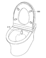
- FIG. 4 is a diagram schematically illustrating an example of an overview of the health monitoring system 100.
- This example is an example in which the measurement apparatus 200 is installed in a Western-style toilet and a health monitoring system is used.
- the type of toilet bowl is not limited to a western style toilet bowl, and a Japanese style toilet bowl or the like may be used for any type of toilet bowl as long as the toilet bowl has water for washing and drainage.
- a part for example, the measurement unit 210) that measures information related to the stored water and urine-containing water of the measuring device 200 is installed in a device immersed in the stored water in the bowl of the toilet bowl.
- the device in which the user identification unit 220 is arranged is located at a position where the user terminal 300 or the like is placed so that the device can read QR code information output from the user terminal 300 owned by the user or information output from the IC card. It is good also as equipment which can be arranged. Thereby, it is possible to perform measurement after identifying the user without inputting user identification information to the measuring apparatus 200 every time the user uses it.
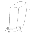
- FIG. 6 is a diagram schematically illustrating an example of the internal structure of the measurement unit 210 according to the first embodiment. Specifically, FIG. 6 shows a configuration example of the film 90 when the film 90 is stored in the measurement unit 210. As shown in FIG. 6, the measurement unit 210 includes a cartridge 30 that stores a plurality of films 90 stacked therein. The cartridge 30 is detachable from the measuring unit 210, and when the film 90 in the cartridge 30 runs out, it can be replaced with a new cartridge 30 in which the film 90 is stored.
- the cartridge 30 stores, for example, a stack of about 30 films 90.
- the number of films 90 that can be stored in the cartridge 30 is not limited.
- Embodiment 1 of the present invention is an example of a strip type in which the film 90 is taken out one by one, and the film 90 is sequentially immersed in water or urine-containing water to present a reagent placed on the film 90. Let color react.
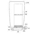
- FIG. 7 is a diagram schematically illustrating another example of the internal structure of the measurement unit 210 according to the first embodiment.
- the measuring unit 210 is provided with an extrusion mechanism 50 for extruding the bottom film 90 of the cartridge 30.
- the extrusion mechanism 50 pushes the film 90 positioned at the bottom of the cartridge 30 to the outside of the measurement unit 210 every time measurement is started.
- the extrusion mechanism 50 may have any configuration as long as it can extrude the film 90 that is stacked and stored.
- the extruding mechanism 50 applies a force in the extruding direction to the film 90 from one side surface portion of the film 90 to extrude the film 90 in the extruding direction.
- the extrusion mechanism 50 may extrude the entire film 90 to the outside of the measuring unit 210 or may extrude a part thereof.
- the push-out mechanism 31 pushes the film 90 positioned at the bottom of the cartridge 30 to the outside of the measurement unit 210 to a position where the clamp unit of the arm 40 can be clamped.
- the measurement unit 210 operates the push-out mechanism 50 in response to a request to start measurement, and pushes the film 90 out of the measurement unit 210.
- the measurement unit 210 includes an arm 40.
- the arm 40 includes a clamping portion 41 for clamping the film 90 at one end thereof.
- the clamping unit 41 clamps the film 90 pushed out of the measurement unit 210.
- the sandwiching portion 41 has, for example, a shape like a ridge, and sandwiches the film 90 by the tips of one sandwiching member 41 a and the other sandwiching member 41 b.
- the sandwiching portion 41 may have any shape or configuration as long as the film 90 can be sandwiched, for example, a shape such as tweezers.
- the arm 40 does not need to have the pinching portion 41 at its tip, and may be shaped like a needle, for example.
- the film 90 may be pierced (penetrated) at the tip of the arm 40 and the film 90 may be held at one end of the arm 40.
- the rotation mechanism 42 can move the holding portion 42 that is one end of the arm 40 in the vertical direction by rotating the arm 40 around the rotation mechanism 42.
- FIG. 8 is a diagram schematically illustrating a configuration example of the measurement unit 210 included in the measurement apparatus 200 according to the first embodiment.
- the measurement unit 210 includes, for example, a rotation mechanism 42 near the lower center of the back surface of the measurement unit 210.
- the holding portion 41 which is the other end of the arm 40, can be moved in the vertical direction.
- the measuring unit 210 can move the film 90 in the vertical direction by operating the rotating mechanism 42 after the clamping unit 41 of the arm 40 clamps the film 90.
- FIG. 9 is a diagram schematically illustrating a state in which the clamping unit 41 of the arm 40 provided in the first embodiment moves in the vertical direction.
- FIG. 9A shows the position of the clamping part 41 when the clamping part 41 of the arm 40 clamps the film 90.
- the clamping part 41 clamps the film 90 above, for example, stored water or urine containing water.
- the sandwiching portion 41 of the arm 40 moves downward by operating the rotation mechanism 42 of the arm 40.
- the measurement part 210 moves the film 90 clamped by the clamping part 41 to the downward direction with the said clamping part 41, and is made to immerse the said film 90 in stored water or urine containing water.
- the arm 40 of the measurement unit 210 stops in a state where the film 90 is immersed in water or urine-containing water, and causes the reagent placed on the film 90 to undergo a color reaction.
- the measuring unit 210 causes the rotation mechanism 42 of the arm 40 to operate again and moves the clamping unit 41 of the arm 40 upward.
- the measuring unit 210 moves the clamping unit 41 of the arm 40 upward to a position where a photographing unit (not shown) of the photographing unit 212 can photograph the reacted film 90.
- the measurement part 210 moves the clamping part 41, for example to the upper direction rather than the stored water or urine containing water.
- the measurement unit 210 images the color reaction of the reagent placed on the film 90 by the imaging unit (not shown) of the imaging unit 212 included in the measurement unit 210.
- FIG. 10 is a diagram schematically illustrating an example of the configuration of the film 90 and the reagent 70 that configure the imaging unit 212.
- the film 90 is formed by using a top film 60 for protecting the surface of the reagent 70 and a support film 80 (for making a support for the reagent) on which the reagent is placed.
- the film 90 constituting the photographing unit 212 can be configured by sandwiching the reagent with the support film 80.
- the top film 60 (1) dissolves the top film 60 at the time of measurement using a water-soluble film, and (2) incorporates a mechanism for peeling the top film 60 into the measurement unit 210 and peels it immediately before the measurement.
- (1) or (2) it is possible to protect the reagent until immediately before the measurement and prevent the reagent from being deteriorated.
- (3) By making the cartridge 30 film 90 in which the film 90 is stored into a highly confidential structure, the amount of air that the film 90 touches immediately before measurement is reduced as much as possible. It is also possible to prevent the deterioration of the reagent.
- the measurement unit 210 releases the film 90 from the clamping unit 41 after the imaging of the color reaction of the reagent in the imaging unit 212 is completed (stops clamping the film 90). Therefore, the film 90 falls into the stored water or the urine-containing water.
- the film 90 is water-soluble, and dissolves in the stored water or urine-containing water by falling into the stored water or urine-containing water. Further, the film 90 is discarded together with the stored water or the urine-containing water when flushed (when the toilet is flushed with urine or the like). If the tip of the arm 40 has a needle-like shape, after filming of the color reaction is completed, the film 90 is once again moved downward to a position where it is immersed in water or urine-containing water. The characteristic film 90 may be dissolved.
- the various DBs are not limited to the storage unit 130 of the server 100 as a storage destination, and may be the storage unit 250 of the measurement device 200 or the storage unit 330 of the user terminal 300. Further, it goes without saying that the data configuration may be changed as appropriate according to the functional configuration of the server 100, processing contents, and the like.
- the toilet information DB is a DB for storing information related to the toilet.
- a toilet model number for storing information related to the toilet.
- water amount water level, mass, volume, etc.
- water temperature water temperature information of the stored water
- washed It includes information such as presence / absence, installation location (latitude / longitude information, address, building name, etc.), use start time (toilet use start time), and the like.
- the toilet information DB may be configured to include information (not shown) regarding the toilet environment, such as amount information of the detergent or the like, or component information of the detergent or the like.
- the toilet information DB holds a record for each toilet.
- Information associated with the toilet model number (for example, toilet bowl shape information, toilet water volume information, etc.) may be stored in the DB, or may be stored in the DB without using a network system such as the Internet. You may search and acquire.
- the threshold value DB is a DB that stores a threshold value that is a criterion for determining whether the measurement result is positive or negative, normal or abnormal.
- the threshold value (absolute) for each measurement item and measurement item absolute information as an absolute index for each measurement item
- threshold values for each measurement item (for each user) reference values as a personalized index for each user for each measurement item
- the measurement / inspection result DB is a DB that stores measurement results and inspection results for each user.
- a user ID user identification information
- measurement items measurement values
- inspection items inspection results
- It includes information such as analysis results, estimation results
- measurement date and time year / month / day, hour / minute / second
- inspection date / time year / month / day, hour / minute / second.
- the dictionary data DB is a DB that stores dictionary data, and includes, for example, information such as measurement values, inspection results (analysis results, estimation results), and the like.
- the dictionary data DB identifies feature vectors created from measured values as so-called teacher data in machine learning.
- the dictionary data stored in the dictionary data DB may be defined and stored in a setting file. If the setting file is used, it is considered that the dictionary data reading and updating processing speed is improved as compared to using the DB.
- the user DB is a DB that stores information for uniquely identifying a user.
- a user ID alphanumeric information uniquely assigned
- a user's name a user's name
- gender a user's name
- height a user's name
- It includes information such as body weight, mass information measured by the measuring device 200, toilet ID of one or more toilets associated with the user.
- the data structure of various DBs has been described above.
- FIG. 12 is a data conceptual diagram showing the association.
- the albumin component in urination is used as input information, and the color development of the film 90 that has reacted with the reagent or the like is measured by the input information using the immunochromatography method using the immunochromatography method.
- the albumin concentration in urine is analyzed, and it is determined whether or not the corresponding threshold value is exceeded for the analysis result. Based on the determination result, the user estimates whether diabetes is positive or negative.
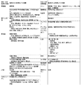
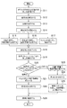
- FIG. 13 is a flowchart illustrating an example of processing executed by the health monitoring system 100.
- the storage unit 130 stores the toilet bowl shape information, the amount of stored water, and the temperature information of the stored water as an initial setting or each time measurement is performed (step S11).
- the user identification unit 220 identifies the user using the IC card, the user terminal 300, etc. (step S12).
- the measurement part 212 may once measure the water temperature of a stored water (not shown).
- the illuminance sensor unit 213 measures the illuminance on the surface of the film 90 (step S13).
- the measurement unit 210 starts each measurement when it is transmitted from the user that the measurement start is input manually by the input means provided in the control unit 230 (step S14). Note that this step can be omitted when the electrode unit 211, the imaging unit 212, and the temperature measurement unit 214 automatically start measurement.
- the temperature measurement unit 214 measures the temperature of the stored water or urine-containing water and generates water temperature information (step S15).
- the electrode unit 211 measures the potential difference between the electrodes and generates voltage information (step S16).
- the measuring unit 210 operates the push-out mechanism 50 to push out and photograph the film 90 positioned at the bottom of the cartridge 30 (step S17). In step 17, the measurement unit 210 first operates the clamping unit 41 of the arm 40 to clamp the film 90 pushed out by the clamping unit 41.
- the measuring unit 210 When the clamping unit 41 clamps the film 90, the measuring unit 210 operates the rotation mechanism 42 to move the clamping unit 41 downward). Thereby, the film 90 clamped by the clamping part 41 is immersed in the stored water or urine containing water.
- the measurement unit 210 stops in a state where the film 90 is immersed in water or urine-containing water, and causes the reagent placed on the film 90 to undergo a color reaction. Thereafter, the measurement unit 210 operates the rotation mechanism 42 to move the clamping unit 41 of the arm 40 upward to a position where a photographing unit (not shown) of the photographing unit 212 can photograph the reacted film 90.
- the measurement unit 210 sends out the film 90 so that the sample pad portion of the film 90 is immersed in water or urine-containing water, and images the RGB luminance signals of the test line and the control line with a photographing means such as a camera (step S21).
- the clamping part 41 of the arm 40 may release the film 90 after the photographing by the photographing means of the photographing part 212 and drop the film 90 into the stored water or the urine-containing water.
- the temperature measuring unit 214 automatically ends the measurement when the temperature to be measured reaches a certain threshold value, and the electrode unit 211 automatically terminates the measurement when the potential difference to be measured reaches a certain threshold value. (Step S18).
- the analysis unit 121 analyzes (calculates) the urine volume by analyzing the sputum fluid using the fluid model obtained by modeling the fluid flowing around the measurement unit 210 based on the shape information, the water amount information, the water temperature information, and the like. (Step S19).
- the correction unit 122 calculates the dilution degree based on the analyzed urine volume information and the water volume information, and the voltage information based on the dilution degree. Is corrected (step S21).
- the analysis unit 123 analyzes the urine component based on the voltage information (after correction) (step S22).
- the correction unit 122 calculates the dilution level based on the analyzed urine volume information and the water volume information, and the imaging is performed based on the dilution level.
- the information is corrected (step S23).
- the correction unit 122 may correct the shooting information based on the illuminance information in addition to the dilution level.
- the analysis unit 123 analyzes the urine component based on the imaging information (after correction) (step S24).
- the analysis unit 123 creates a feature vector based on the analysis result, and identifies the created feature vector based on training data (dictionary data) (step S25).
- the estimation unit 124 estimates a user's disease based on the analyzed urination information (for example, analyzed urine component) (step S26).
- the second embodiment is an embodiment in which the shape and material of the measurement unit 210 are devised so that an object such as toilet paper is less likely to adhere to the measurement unit 210.
- the configuration described in the second embodiment is applicable to both the first embodiment and the following embodiment.
- FIG. 14 is a diagram schematically illustrating an example of an overview of the measurement unit 210 according to the second embodiment.
- the measurement unit 210 has, for example, a substantially streamlined shape with the top as a tip.
- the measurement unit 210 may have, for example, a substantially triangular pyramid shape or a substantially conical shape with the upper end as a tip.
- the measurement unit 210 may have a trapezoidal shape with the top as a tip.
- the measurement unit 210 has, for example, a tapered shape in which the casing becomes thinner from the lower part toward the upper part.
- FIG. 15 is a diagram schematically illustrating another example of the appearance of the measurement unit 210 according to the second embodiment.
- the measurement unit 210 has, for example, a substantially streamlined shape with a cross-section at the top. Therefore, as shown in FIG. 15, the measurement unit 210 can flip an object from above to the front of the measurement unit 210. Therefore, an object such as toilet paper that hits from the top is less likely to adhere to the measurement unit 210.
- the measuring unit 210 has a shape in which the side surface also tapers from the lower part to the upper part, even if the object hits the side part, the object can be repelled, and the object adheres to the measuring unit 210. It becomes difficult to do.
- the measuring unit 210 may have any shape as long as an object from above does not easily adhere.
- the measurement unit 210 of the second embodiment may be coated such that the material is less likely to adhere to toilet paper.
- the coating material is an affinity coating.
- the coating material may be a fluororesin. Since the fluororesin has a small coefficient of friction, it is difficult for an object to adhere to the measurement unit 210.
- the measurement unit 210 coated with a fluororesin is less likely to adhere not only objects such as toilet paper but also oils and fats, dirt, and the like. Therefore, the measurement unit 210 can be kept clean.
- the measurement unit 210 of the second embodiment may have a surface with fine irregularities.
- the surface of the measurement unit 210 is formed with unevenness that undulates in a chord wave shape.
- the surface of the measurement part 210 may be formed with unevenness whose slope of the convex part is less than 10 degrees, for example. Note that the slope of the slope of the convex portion does not need to be less than 10 degrees, and may be any slope as long as the object is hard to adhere to. Since the surface of the measurement unit 210 is uneven, objects such as toilet paper, oils and dirt, and dirt are less likely to adhere to the measurement unit 210.
- the third embodiment is an embodiment in which a rotation mechanism is provided on the back surface of the measurement unit 210 and the measurement unit 210 can be tilted to the left and right with the flow of water. Note that the configuration described in the third embodiment can be applied to any of the first embodiment, the second embodiment, and the following embodiment.
- tornado cleaning As one of the methods of cleaning the toilet bowl with cleaning water (water, rainwater, etc.).
- the flushing water flows in the lateral direction from the upper part of the toilet bowl, and the flushing water flows in a vortex in the toilet bowl, thereby washing the inside of the toilet bowl.
- the amount of washing water used for washing in the toilet bowl can be reduced, for example, by the washing water flowing in the toilet bowl vigorously.
- the measurement unit 210 when the inside of the toilet bowl is washed by tornado washing, it is necessary that the washing water flows in a swirl.
- the measurement unit 210 when the measurement unit 210 is set in the toilet bowl, the measurement unit 210 impedes the flow of washing water. There is a possibility that. In such a case, washing in the toilet bowl with washing water is suppressed.
- the measurement unit 210 by allowing the measurement unit 210 to rotate around a part of the back surface, the measurement unit 210 can rotate along the flow of cleaning water in tornado cleaning. To prevent the flow of water.
- FIG. 16 is a diagram schematically illustrating a configuration example of the measurement unit 210 included in the measurement apparatus 200 according to the third embodiment.
- a part of the back surface of the measurement unit 210 is rotatably connected to a fixing unit 700 fixed to the wall surface of the toilet bowl.
- the measurement unit 210 includes a protrusion at the center of the back surface thereof, and is rotatably connected to the suction cup 700 via the protrusion.
- the measurement unit 210 includes a rotation mechanism 710. Specifically, when the protrusion on the back surface of the measurement unit 210 is fitted into the recess provided in the fixing unit 700, the measurement unit 210 can rotate around the protrusion.
- rotation mechanism illustrated in FIG. 16 is an example, and the rotation mechanism 710 may have any form.
- the fixing part 700 is a semi-cylindrical rubber sucker as shown in FIG. 16, and can be fixed to the wall surface of the toilet.
- fixed part 700 does not need to be a rubber suction cup, You may fix to the wall surface of a toilet bowl with what kind of form.
- the fixing unit 700 may be provided in advance as a part of the toilet bowl.
- fixed part 700 may be fixed to the wall surface of the toilet bowl with the adhesive agent etc., for example.
- FIG. 17 is a schematic diagram illustrating a usage mode of the measurement unit 210 in the third embodiment.
- the measuring unit 210 when the toilet bowl is washed by so-called tornado washing, the measuring unit 210 can be rotated in the direction in which the washing water flows by the rotation mechanism shown in FIG.
- the measurement unit 210 when the cleaning water flows from the lateral direction of the measurement unit 210, the measurement unit 210 rotates in the direction in which the cleaning water flows (leftward in FIG. 17), It can reduce that the washing in the toilet bowl with the washing water is suppressed without inhibiting the flow of the washing water.
- the measuring unit 210 is rotatable with respect to the wall surface of the toilet bowl by the rotation mechanism 710, so that it rotates greatly when the flow of washing water is strong, and conversely small when the flow is weak. Rotate.
- the measurement part 210 can change a rotation angle with the strength of washing water.
- a part of the back surface of the measurement unit 210 is fixed to the fixing unit 700 bonded to the wall surface in the toilet, so that the measurement unit 210 can rotate along the flow of washing water in the tornado cleaning. Therefore, it is possible to prevent the flow of the washing water from being hindered.
- the measurement unit 210 can be prevented from being inverted due to the flow of cleaning water. If the fixing part 700 is not provided, the measuring part 210 may be shaken irregularly and greatly by the flow of cleaning water, and the front surface and the back surface may be reversed. In this case, since the measurement by the measurement unit 210 is not correctly executed, the user needs to reposition the measurement unit 210 in the correct direction.
- the back surface of the measurement unit 210 is rotatably fixed to the wall surface of the toilet bowl as shown in FIG. 16, at least the measurement unit 210 is not reversed between the front surface and the back surface. Therefore, there is an effect that the user does not need to cure the arrangement of the measurement unit 210 in which the front surface and the back surface are reversed.
- the measuring apparatus 200 does not necessarily need to include the fixing unit 700.
- the measurement unit 200 may be configured to be hung at the top of a cable or string.
- the measuring apparatus 200 main body is suspended by the cable or the string so that the main body of the measuring apparatus 200 can be swung from side to side without resistance to the flow of water so as to cope with tornado cleaning.
- the measuring device 200 has a weight that can be moved left and right by the flow of cleaning water.
- the measuring device 200 is provided in front of the water in the toilet, but the position of the measuring device 200 is not limited to the front, and may be any position.
- the deepest portion of the stored water in the toilet increases the force (pull-in force) for draining the stored water due to the swirl of water caused by tornado cleaning.
- the tornado cleaning excretion can be efficiently excreted by such a pulling force. Therefore, in order to avoid hindering the pulling force, it is preferable that the measuring device 200 is attached not to the deepest part of the reservoir water in the toilet but to the other part of the toilet.
- the measuring device 200 is preferably attached to the lateral side surface of the pooled water portion in the toilet or the front side surface of the pooled water portion on the opposite side of the mounting position of the measuring device 200 of FIG. Thereby, the measuring apparatus 200 can prevent the flow of the washing water for the tornado washing from being obstructed, and can reduce the amount of the washing water used for washing in the toilet bowl.
- Embodiment 3 of the present invention by providing the measurement unit 210 so that the measurement unit 210 does not inhibit the flow of cleaning water in tornado cleaning, the flow of the cleaning water is prevented from being inhibited. be able to.
- the fourth embodiment is an embodiment in which the weight of the user sitting on the toilet seat can be measured by attaching the pressure sensor 800 to the toilet seat of the toilet bowl. Note that the configuration described in the fourth embodiment is applicable to any of the first, second, and third embodiments.
- FIG. 18 is a diagram illustrating a configuration example of a toilet according to the fourth embodiment.
- the pressure sensor 800 is attached to the back surface of the toilet seat of the toilet bowl.
- the pressure sensor 800 measures the weight of the user sitting on the toilet seat.
- the pressure sensor 800 measures the weight applied from above when the user sits on the toilet seat.
- four pressure sensors 800 are provided on the back surface of the toilet seat.
- the number of pressure sensors may be any number, for example, one.
- the pressure sensor 800 is used to calculate a change in the weight of the user, and measures the weight applied from above. For example, it is assumed that the pressure sensor 800 measures 30 [Kg] with the user sitting on the toilet seat at a predetermined timing. Thereafter, it is assumed that the pressure sensor 800 measures 31 [kg] with the user sitting on the toilet seat at another timing. In this case, it is calculated that the user's weight has increased by 1 [kg] between a predetermined timing and another timing. In addition, when the pressure sensor 800 is provided with two or more in the toilet seat, the change of a user's weight is calculated based on the sum total of the measured value in the said several pressure sensor. Thereafter, the calculated change is added to or subtracted from the weight of the user at a predetermined timing, and the weight of the user at another timing is obtained.
- the change in body weight may be calculated by multiplying the measured value of the pressure sensor 800 by a predetermined weight according to the number of pressure sensors 800 attached to the toilet seat, the position thereof, and the like. For example, when there is only one pressure sensor 800 provided on the toilet seat and the toilet seat is supported at four points, the change in the weight of the user is four times the measured value. .
- the predetermined weight may be determined in consideration of the position of the user's center of gravity when the user is sitting on the toilet seat.
- the predetermined timing and the other timing may be, for example, a timing when the health monitoring system 500 is used.
- the weight change can be calculated every time the health monitoring system is used, and the user's weight can be obtained each time the health monitoring system is used.
- the pressure sensor 800 can measure the actual weight of the user, and in this case, the user adds all of his / her weight to the toilet seat. For example, the user raises his / her foot while sitting on the toilet seat so that his / her weight is added only to the toilet seat.
- the weight of the user measured using the pressure sensor 800 is stored in the user DB of the storage unit 130 provided in the server 100.
- the pressure sensor 800 stores the weight of the user in the user DB via the measurement unit 210 of the measurement device 200.
- the user DB updates the weight of the user every time the weight of the user is notified from the measurement device 200.
- the weight of the user sitting on the toilet seat can be measured by attaching the pressure sensor 800 to the toilet seat of the toilet bowl. Therefore, for example, the user can measure and calculate his / her latest weight every time the toilet is used. In addition, since the user can measure and calculate his / her body weight simply by sitting on the toilet seat, the user can easily measure and calculate his / her body weight as compared with the case of measuring with a weight scale.
- the latest weight of the user can be measured and calculated each time the user uses the health monitoring system 500. Therefore, it becomes possible to estimate the disease of the user based on the latest weight of the user when using the health monitoring system.
- the health monitoring system according to the present invention can be used as part of telemedicine in conjunction with a medical institution or the like.
- the user DB stored in the storage unit 130 stores information on medical institutions, doctors, and the like related to each user, and the measurement values and test result data of the DB are updated when the measurement / test result DB is updated.
- doctors and the like can remotely perform health examinations, guidance, and the like based on the transmitted data.
- the health monitoring system according to the present invention is similarly used by a doctor, a pharmacist, a pharmaceutical company, etc. to remotely monitor medication (whether the prescribed drug is applied) or check drug metabolism (check whether the prescribed drug is effective).
- the health monitoring system according to the present invention cooperates with the system of a pharmaceutical company or health insurance association, and the health monitoring system according to the present invention uses time-series vital data generated from measurement / test result information stored in the storage unit 130. It can also be used for data marketing business. Similarly, vital data can also be used to simulate how healthcare costs can be reduced in conjunction with insurance company and health insurance association systems.
- the generated vital data with daily life logs recorded by wearable devices linked to the health monitoring system, it can be used for services that provide more specific health and beauty advice.
- it can be used for modeling what kind of health a person will live in.
- the extracted nutrient is displayed on the display unit 330 of the user terminal 300, and a meal menu (ingested based on the extracted nutrient is also displayed.
- Food ingredients such as vegetables to be included
- supplements may be displayed on the display unit 330 of the user terminal 300 and suggested.
- vital data can be classified into types, and supplements for supplementing nutrients that are deficient in the body can be proposed for each type.
- the service can be applied not only to general households and individuals but also to health management such as athletes.
- personalized cosmetics can be proposed especially to users who are expected to have problems with their skin and hair.
- the health monitoring system according to the present invention can be used for modeling, for example, what kind of genome human beings live in what kind of health state by linking genome analysis results in addition to vital data and life logs. it can.
- modeling information provides insurance companies with information on their health condition predicted by the modeling, and the insurance companies, etc. as information when considering and determining enrollment and insurance premiums based on the forecast information Can be used.
- Each functional unit of the server 100, the measuring apparatus 200, and the user terminal 300 is realized by a logic circuit (hardware) or a dedicated circuit formed in an integrated circuit (IC (Integrated Circuit) chip, LSI (Large Scale Integration)) or the like. Alternatively, it may be realized by software using a CPU (Central Processing Unit) and a memory. Each functional unit may be realized by one or a plurality of integrated circuits, and the functions of the plurality of functional units may be realized by a single integrated circuit.
- An LSI may be called a VLSI, a super LSI, an ultra LSI, or the like depending on the degree of integration.
- the “circuit” may include the meaning of digital processing by a computer, that is, functional processing by software. Further, the circuit may be realized by a reconfigurable circuit (for example, FPGA: Field Programmable Gate) Away).
- the function units of the server 100, the measurement device 200, and the user terminal 300 are realized by software
- the function units of the server 100, the measurement device 200, or the user terminal 300 are included in a display information generation program that is software that realizes each function.
- CPU for executing instructions, health monitoring program and ROM (Read Only Memory) in which various data are recorded so as to be readable by a computer (or CPU) or storage device (these are referred to as “recording medium”), health monitoring program RAM (Random Access Memory) is available.
- the computer or CPU reads the health monitoring program from the recording medium and executes it to achieve the object of the present invention.
- a “non-temporary tangible medium” such as a tape, a disk, a card, a semiconductor memory, a programmable logic circuit, or the like can be used.
- the health monitoring program may be supplied to the computer via any transmission medium (such as a communication network or a broadcast wave) that can transmit the health monitoring program.
- the present invention can also be realized in the form of a data signal embedded in a carrier wave, in which the health monitoring program is embodied by electronic transmission.
- the health monitoring program can be implemented using, for example, a script language such as ActionScript or JavaScript (registered trademark), an object-oriented programming language such as Objective-C or Java (registered trademark), or a markup language such as HTML5. .
- a script language such as ActionScript or JavaScript (registered trademark)
- an object-oriented programming language such as Objective-C or Java (registered trademark)
- a markup language such as HTML5.
- Server 110 Communication Unit 120 Control Unit 130 Storage Unit 200 Measuring Device 210 Measuring Unit (Measuring Device) 220 User identification unit (measuring device) 230 Control unit (measuring device) 240 Communication unit (measuring device) 250 Storage unit (measuring device) 300 user terminal 310 communication unit (user terminal) 320 Control unit (user terminal) 330 Display unit (user terminal) 340 storage unit (user terminal)
Abstract
健康モニタリングにあたって、簡易的に排尿情報を解析し、疾病を推測することができる健康モニタリングシステムを提供する。 本発明に係る健康モニタリングシステムは、便器の使用者の排尿が流れ込んだ溜水中の流体に関する流体情報を測定する測定部と、流体情報に基づいて、流体をモデル化した流体モデルを分析することで排尿を解析する解析部と、排尿の排尿情報に基づいて、使用者の疾病を推測する推測部とを備え、前記測定部は、排尿が流れ込んだ溜水の成分に応じて色が変化するフィルムを格納するカートリッジを含み、前記流体情報を測定するごとに、当該カートリッジから当該測定に用いるフィルムを押し出すことを特徴とする。
Description
本発明は、健康モニタリングシステム、健康モニタリング方法および健康モニタリングプログラムに関し、特に便器に設置して排尿を解析し、疾病を推測する健康モニタリングシステム、健康モニタリング方法および健康モニタリングプログラムに関する。
近年の健康志向の高まりを受けて、従来から、尿の状態(量や成分)を分析して健康状態をモニタリングし、アドバイスするサービスが多く存在する。身体の異常がある場合は、尿の状態も変化しやすく、身体の異常を発見するには、尿の状態を日頃からモニタリングをすることが効果的である。
このような尿の分析技術として、例えば、特許文献1には、実測された人の1回の尿中における特定成分の濃度と、実測された1日の全尿中における特定成分の濃度との間の相関関係を表すデータを記憶しており、当該相関関係を用いて被測定者の1日の全尿中における特定成分の濃度を換算して求めること、当該求めた濃度より被測定者の1日の全尿中における特定成分の排泄量を算出する排尿情報測定装置が開示されている。
また、特許文献2には、尿を貯える便器のボウルと、当該ボウルに蓄えられた尿の体積や重量を計測する尿データ計測手段によって、排尿量、尿流率を算出する排尿情報測定装置が開示されている。特許文献2記載の排尿測定装置は、排尿開始時または排尿終了時の各水位もしくは水位変化率によって排尿量および尿流率を算出し、当該算出したデータに所定の振動モデルを適用してパーティクルフィルタによって処理することによって排尿情報を算出するものであった。
しかしながら、特許文献1記載の発明では、大きく筐体とセンサ部から構成され、被測定者等の手で筐体を把持してセンサ部に被測定者が排泄した尿を振りかけなければならず、使い勝手が必ずしも十分ではなかった。
また、特許文献2記載の発明においても、便器のボウルに蓄えられた尿の体積や重量を計測する手段として、ボウル内の溜水の水位データを用いていたり、下水配管の下水圧測定を用いていたりと便器を構成する要素を使用しているため、既設の便器への適用が不可能であった。したがって、特許文献2に記載の排尿情報測定装置においては、汎用性に乏しく、使い勝手が必ずしも十分ではなかった。
そこで、本発明は、尿成分分析等の排尿の解析および当該解析結果に基づく疾病の推測にあたって、簡易的で使い勝手の良い健康モニタリングシステム、健康モニタリング方法および健康モニタリングプログラムを提供することを目的とする。
本発明に係る健康モニタリングシステムは、便器の使用者の排尿が流れ込んだ溜水中の流体に関する流体情報を測定する測定部と、流体情報に基づいて、流体が流れる領域をモデル化した流体モデルを分析することで排尿を解析する解析部と、排尿の排尿情報に基づいて、使用者の疾病を推測する推測部とを備え、当該測定部は、排尿が流れ込んだ溜水の成分に応じて色が変化するフィルムを格納するカートリッジを含み、当該流体情報を測定するごとに、当該カートリッジから当該測定に用いるフィルムを押し出すことを特徴とする。
さらに、本発明に係る健康モニタリングシステムは、測定部は、当該カートリッジに積層して格納された複数のフィルムのうち測定に用いるフィルムを、当該カートリッジの外に押し出す押出機構を含んでいてもよい。
さらに、本発明に係る健康モニタリングシステムは、測定部が、当該カートリッジから押し出されたフィルムを挟持する挟持部を備えるアームをさらに含み、当該アームを動作することで、当該挟持部に挟持されたフィルムを使用者の排尿が流れ込んだ溜水に浸漬させてもよい。
さらに、本発明に係る健康モニタリングシステムは、測定部が、前記アームの一端と回転自在に連結する回転機構をさらに含み、当該アームを当該回転機構により回転させることで、当該アームの他端に備わる挟持部を、使用者の排尿が流れ込んだ溜水に浸漬する位置まで移動させてもよい。
さらに、本発明に係る健康モニタリングシステムは、フィルムを撮影して撮影情報を生成する撮影手段を含む撮影部を備え、測定部が、アームを動作することで、使用者の排尿が流れ込んだ溜水に浸漬されたフィルムを、撮影部が当該フィルムを撮影可能な位置まで移動させてもよい。
さらに、本発明に係る健康モニタリングシステムは、カートリッジは、前記測定部から着脱可能であり、測定部において、当該カートリッジに格納されたフィルムが無くなった場合に、当該カートリッジを複数のフィルムが格納された新たなカートリッジに交換可能であってもよい。
さらに、本発明に係る健康モニタリングシステムは、便器ごとのボウルの形状情報および溜水の水量情報を記憶する記憶部を備え、流体情報は、溜水または排尿が流れ込んだ溜水の少なくともいずれか一つの水温を測定して生成した水温情報を含み、解析部は、流体情報に加え、形状情報または水量情報の少なくともいずれか一つに基づいて、排尿を解析してもよい。
さらに、本発明に係る健康モニタリングシステムは、溜水または排尿が流れ込んだ溜水に浸漬した二つの電極間の電位差を測定して電圧情報を生成し、水量情報および排尿の尿量を含む排尿情報に基づいて、電圧情報を補正する補正部と、補正した電圧情報に基づいて尿成分を分析する分析部と、を備えていてもよい。
さらに、本発明に係る健康モニタリングシステムは、測定部が、水温情報または電圧情報の少なくともいずれか一つが所定の閾値に達した際に、排尿が流れ込んだ溜水の水温または電位差の少なくともいずれか一つの測定を開始または終了してもよい。
さらに、本発明に係る健康モニタリングシステムは、推測部が、撮影情報から特徴ベクトルを作成し、該作成した特徴ベクトルを訓練データにより識別し、該識別した特徴ベクトルに基づいて、疾病を推測してもよい。
さらに、本発明に係る健康モニタリングシステムは、使用者が所有する端末またはICカードから出力するユーザ識別情報に基づいて、使用者を識別するユーザ識別部をさらに備え、推測部は、当該識別の結果に基づいて、使用者ごとに疾病を推測してもよい。
さらに、本発明に係る健康モニタリングシステムは、ユーザ識別部が、使用者が便座を使用した際に便器の便座が受ける使用者の重量を計測し重量情報を生成する計測部をさらに備え、当該重量情報に基づいて、使用者を識別してもよい。
本発明に係る健康モニタリングシステム方法は、便器の使用者の排尿が流れ込んだ溜水中の流体に関する流体情報を測定する測定ステップと、流体情報に基づいて、流体が流れる領域をモデル化した流体モデルを分析することで排尿を解析する解析ステップと、排尿の排尿情報に基づいて、使用者の疾病を推測する推測ステップと、流体情報を測定するごとに、排尿が流れ込んだ溜水の成分に応じて色が変化するフィルムを格納するカートリッジから、当該測定に用いるフィルムを押し出す押出ステップを含む。
本発明に係る健康モニタリングプログラムは、コンピュータを制御するプログラムであって、便器の使用者の排尿が流れ込んだ溜水中の流体に関する流体情報を測定する測定機能と、流体情報に基づいて、流体が流れる領域をモデル化した流体モデルを分析することで排尿を解析する解析機能と、排尿の排尿情報に基づいて、使用者の疾病を推測する推測機能と、流体情報を測定するごとに、排尿が流れ込んだ溜水の成分に応じて色が変化するフィルムを格納するカートリッジから、当該測定に用いるフィルムを押し出す押出機能をコンピュータにより実現させる。
本発明に係る健康モニタリングシステムは、便器の使用者の排尿が流れ込んだ溜水中の流体に関する流体情報を測定する測定部と、流体情報に基づいて、流体が流れる領域をモデル化した流体モデルを解析することで排尿を解析する解析部と、排尿の排尿情報に基づいて、使用者の疾病を推測する推測部とを備えるものである。
これらの構成により、尿成分の測定にあたって、既設の便器に本発明に係る健康モニタリングシステムを設置するだけで、被測定者は通常どおり排泄するだけで尿成分を測定できるため、装置に排尿を振りかけることにより測定するよりも簡易的に、また、衛生的に測定することができ、使い勝手を向上できる。
また、本発明に係る健康モニタリングシステムおよび健康モニタリング方法は、流体シミュレーションにより流体の動きを解析して尿量を解析しているため、排尿が溜水によりどの程度希釈されたかを考慮することができ、精度よく分析することができる。
本発明に係る健康モニタリングシステムおよび健康モニタリング方法は、排尿情報の解析および疾病の推測にあたって、簡易性および使い勝手を向上できる。
以下、本発明の実施態様について、図面を参照しながら説明する。
<実施形態1>
<概要>
図1は、本発明の第1の実施形態に係る健康モニタリングシステム構成の例を示すシステム図である。
<概要>
図1は、本発明の第1の実施形態に係る健康モニタリングシステム構成の例を示すシステム図である。
図1に示すように、当該システムは、サーバ100、測定装置200、ユーザ端末300を含む。サーバ100は、ネットワーク400を介して測定装置200およびユーザ端末300を接続される。なお、図1において、説明を簡単にするためにサーバ100、測定装置200およびユーザ端末300は各々1台だけ示してあるが、これ以上存在してもよいことは言うまでもない。また、ユーザ端末300の具体的な機器は、図示のように、スマートフォンに限定されず、例えば、携帯端末、タブレット端末、パーソナルコンピュータ、その他の電子機器であってもよい。ユーザ端末300は、例えば、コンピュータ(例えば、デスクトップ、ラップトップ、タブレットなど)、メディアコンピュータプラットホーム(例えば、ケーブル、衛星セットトップボックス、デジタルビデオレコーダ)、ハンドヘルドコンピュータデバイス(例えば、PDA(personal digital assistant)、電子メールクライアントなど)、携帯電話(例えばスマートフォン、フィーチャーフォンなど)、ウェアラブル端末(メガネ型デバイス、時計型デバイスなど)あるいは他種のコンピュータ、またはコミュニケーションプラットホームを含むが、本発明はそれらに限定されるものではない。さらに、当該システムは、クラウドサービス(パブリッククラウド、プライベートクラウドいずれも含む)を用いてもよいし、対象の施設内に物理的に共用または専用サーバを設けてサービスを提供してもよい。
ユーザ端末300は、本発明の実施形態1による健康モニタリングシステムの一部である健康状態のモニタリング結果(分析結果、推測結果含む)を表示するアプリケーション(以降、「ヘルスモニタリングアプリ」という)を搭載し、図3に示すように、ヘルスモニタリングアプリの表示を閲覧して自身の健康状態をチェックできる。
健康モニタリングシステム500は、一例として、図3に示すように、測定装置200を既設の便器等に設置し、測定装置200において便器の使用者の排尿が流れ込んだ溜水中の流体に関する流体情報を測定し、サーバ100において当該測定された流体情報に基づいて、流体が流れる領域をモデル化した流体モデルを解析することで排尿を解析し、解析された排尿の排尿情報に基づいて、使用者の疾病を推測することができる。これにより、健康モニタリング500は、例えば、自宅または仕事場に居ながら、かつ、使用者は通常の排尿行為を行うだけで疾病の兆候や疾病であることを判定することができるため、簡易的で使い勝手がよく、持続可能性の高い健康モニタリングサービスを提供することができる。
また、健康モニタリングシステム500は、自宅や仕事場への適用に限定されず、介護施設や病院においても患者の健康管理に利用することもでき、運営側のリスク軽減を図ることもできる。ここで、「排尿情報」とは、使用者の排尿に関する種々の情報をいい、排尿の尿量、尿温、尿成分等を含んで構成してもよい。
なお、実施形態1では、クラウドコンピューティング形式を用いた例を示したが、これに限定されず、例えば、測定装置200単体または測定装置200およびユーザ端末300で健康モニタリングシステム500を構成してもよい。また、本例では、クラウドサービスを用いたサービスの例を示したが、人工知能(例えば、ディープラーニングなどによる機械学習によるもの)を用いたクラウドドクターサービス(例えば、ネットワーク越しに患者の健康状態や体調の診療するサービス)やクラウドマザーサービス(例えば、ネットワーク越しに子供の健康状態や体調のモニタリングするサービス)に用いることもできる。
<構成>
図2は、本発明の実施形態1に係る健康モニタリングシステムの構成例を示すブロック図である。
図2は、本発明の実施形態1に係る健康モニタリングシステムの構成例を示すブロック図である。
図2に示すように、実施形態1に係る健康モニタリングシステムは、測定部210を含む測定装置200と、解析部121および推測部124を含む制御部を備えるサーバ100とを含む。
測定装置200の測定部210は、便器の使用者の排尿が流れ込んだ溜水中の流体に関する流体情報を測定する。
サーバ100の解析部121は、測定部120が測定した流体情報に基づいて、流体をモデル化した流体モデルを分析することで排尿を解析する。また、サーバ100の推測部124が、排尿の排尿情報に基づいて、使用者の疾病を推測する。
そして、本発明の実施形態1では、測定部210は、排尿が流れ込んだ溜水の成分に応じて色が変化するフィルムを格納するカートリッジを含み、当該流体情報を測定するごとに、当該カートリッジから当該測定に用いるフィルムを押し出す。
測定部210が、上記のように、流体情報の測定に用いるフィルムを格納したカートリッジを備え、当該流体情報の測定の都度、当該カートリッジから測定に用いるフィルムを押し出すため、被測定者が検査に用いるフィルムを準備するなどの手間をかけずに、尿成分を測定可能である。そのため、被測定者は、例えば、装置に排尿を振りかけることにより測定するよりも簡易的に、また、衛生的に測定することができ、使い勝手を向上できる。
以下、サーバ100、測定装置200、ユーザ端末300の構成についてより詳細に説明する。図3は、サーバ100、測定装置200、ユーザ端末300の機能構成の一例を示すブロック図である。なお、各部の配置においては、各機器の動作環境および状況等に応じて、サーバ100、測定装置200、ユーザ端末300間で適宜変更してもよい。例えば、サーバ100の解析部121、補正部122、分析部123、推測部124は測定装置200の制御部230に配置してもよいし、ユーザ端末200の制御部320に配置してもよい。図3に示すように、サーバ100は、通信部110と、制御部120と、記憶部130を含んで構成される。
また、サーバ100は、多段構成とすることができ、例えば、施設内に設置するサーバ(中継サーバ)と、複数の施設を含む特定のエリアまたは全てのエリアを包括するサーバから構成してもよい。中継サーバの送信タイミングとしては、(1)周期的に(例えば、記憶部130のキャパシティ等を考慮して定めた一定時間ごとに)、(3)記憶部250の記憶容量に閾値を設定して当該閾値に達した際などを送信タイミングとしてもよい。
通信部110は、受信部111および送信部112を備え、ネットワーク400を介して、測定装置200およびユーザ端末300との通信を実行する機能を有する。当該通信は、有線、無線のいずれでもよく、また、互いの通信が実行できるのであれば、どのような通信プロトコルを用いてもよい。ネットワーク400は、例えば、LTE(Long Term Evolution)、LANs(Local Area Networks)、WANs(Wide Area Networks)、MANs(Metropolitan Area Networks)、ISDNs(Integrated Service Digital Networks)などのネットワークや、無線LANs、CDMA(Code Division Multiple Access)、ブルートゥース(Bluetooth(登録商標))、衛星通信などのなどのネットワークであり、有線・無線を問わず、情報処理装置100や情報処理端末200が互いに通信可能であれば、どのようなネットワークであってもよい。
受信部111は、ネットワーク400を介して、制御部120の制御に従って、各測定装置200および各ユーザ端末300から測定データ等を受信し、当該測定データを制御部120に伝達する機能を有する。具体的には、受信部111は、測定装置200から便器のボウル内の溜水および当該溜水に便器の使用者の排尿を含んだ水(以降、「排尿含有水」という)の水温情報、排尿含有水に電極を浸漬して電極間の電位差による電圧情報、使用者を識別するユーザ識別情報、照度情報および撮影部212において試薬が反応したフィルム90を撮影した撮影情報(以降、「撮影情報」という)を受信し、制御部120に伝達する。
送信部112は、ネットワーク400を介して、制御部120の制御に従って、各測定装置200に制御データ等および各ユーザ端末300にモニタリング結果データ等を送信する機能を有する。具体的には、例えば、送信部112は、ユーザ識別部220の制御のための記憶部130に記憶する使用者情報(例えば、ID情報など)、測定部210の測定および撮影並びにユーザ識別部220の識別に必要な動的パラメータデータ等を測定装置200に送信し、また、分析した尿成分に係る分析結果、推測された疾病の陽性および陰性に係る推測結果等のモニタリング結果を表す表示データをユーザ端末300に送信する。
制御部120は、解析部121、補正部122、分析部123および推測部124を含んで構成され、サーバ100の各部を制御する機能を有するプロセッサである。また、制御部120は、分析部123から分析結果を伝達されると、また、推測部124から推測結果を伝達されると、ユーザ端末300の表示部330にテキスト、表またはグラフで表示するための表示データを生成する。制御部120は、当該生成した表示データをユーザ端末300に送信するために、送信部112に伝達する。
解析部121は、流体情報に基づいて、流体が流れる領域をモデル化した流体モデルを解析することで、排尿を解析する機能を有する。ここで「流体情報」とは、流体解析に必要な情報をいい、便器のボウルの形状情報(以降、「形状情報」という)、便器のボウル内の溜水の水量情報および水温情報等から構成される。
解析部121は、具体的には、例えば、便器のボウルの形状情報、便器のボウル内の溜水の水量情報または水温情報等の少なくともいずれか一つに基づいて、測定部210の周囲を流れる流体をモデル化した流体モデルに基づいて、測定部210の周囲の流体を解析して尿量を算出することで排尿を解析する。また、解析部121は、便器のボウルの形状情報、便器のボウル内の溜水の水量情報、水温情報以外にも、洗剤等の量情報または洗剤等の成分情報等のトイレ環境に関する情報の少なくともいずれか一つを加えて、これらに基づいて、流体をモデル化等して排尿情報を解析してもよい。これらにより、排尿のみを採取して尿量を測定したり、便器のボウルや排水管に付設した測定器等で水位変化率から尿量を測定したりする必要がなく、使用者にとって使い勝手のよい健康モニタリングシステムを提供することができる。
当該流体のモデル化は、例えば、SVM(Support vector machine)等による回帰分析を用いて、測定した溜水および排尿含有の水温から生成した水温情報に基づき、溜水および排尿含有水の水温がどの様に変化し最終的に収束するのかの予測モデルを構築して分析すること考えられる。また、当該回帰分析において、SVMにカーネル法で導き出したデータ構造を組み合わせて分析してもよい。また、他の例として、MCMC法(Markov Chain Monte Carlo)(マルコフ連鎖モンテカルロ法)による回帰分析を用いて、回帰モデルを構築して分析することも考えられる。さらに、これら以外にも、流体シミュレーションを用いて流体領域をモデル化する例として有限要素法やCFD(Computational Fluid Dynamics)法を用いることも考えられる。
補正部122は、水量情報および尿量を含む排尿情報に基づいて、電圧情報を補正する機能を有する。具体的には、例えば、補正部122は、尿量を水量および尿量の和で除算することにより希釈度合を算出し、当該希釈度合より電圧情報を補正する。これにより、便器のボウル内の溜水等による希釈を考慮した電圧情報の取得、ひいては尿成分の分析することができる。
補正部122は、照度情報に基づいて撮影情報を補正する機能を有する。ここで「照度情報」とは、撮影部212のフィルム面の照度(明るさ)(lx)を表す情報をいう。具体的には、例えば、補正部122は、照度情報に基づいてRGB値の明度を適切な値に調節することで補正する。これにより、照明による影響を考慮したRGB値を得ることができ、精度よく色測定をすることができる。
分析部123は、電圧情報または補正した電圧情報(以降、「電圧情報(補正後)」という)に基づいて、尿成分を分析する機能を有する。分析部123は、具体的には、例えば、電圧情報(補正後)に基づいて、尿中の塩化物、ブドウ糖、カリウム、ナトリウム、尿素等の成分の分子濃度を分析する。また、図12に示すようにph値を分析することもできる。これにより、排尿が溜水で希釈されても精度よく分析することができる。また、分析部123は、当該分析結果をユーザ端末300に表示させる表示データを生成するために、制御部120に伝達する。
分析部123は、撮影情報または補正した撮影情報(以降、「撮影情報(補正後)」という)に基づいて、尿成分を分析する機能も有する。具体的には、例えば、分析部123は、撮影情報(RGB値)に基づいて試薬に対する尿中の特定成分の発色反応の色を測定し、当該色に対応する尿中の特定成分またはその濃度を分析する。また、分析部123は、当該分析結果をユーザ端末300に表示させる表示データを生成するために、制御部120に伝達する。これにより、バイオアッセイ(イムノクロマト法など)による尿中の特定成分およびその濃度の分析を、人による目視等ではなく、人を介さず自動で簡易的に実現することができる。
推測部124は、解析された排尿の排尿情報に基づいて、使用者の疾病を推測する機能を有する。推測部124は、具体的には、例えば、分析された尿中の特定成分(具体的には、例えば、当該成分の濃度等)に基づいて、使用者の疾病を推測する。一例として、図12に示すように、尿中のブドウ糖の濃度を分析することで尿糖値を算出し、糖尿病が陽性であるか、または陰性であるかを推測する。また、図12には、その他の測定部210の測定または分析部123の分析結果(「測定・分析結果」という)と、当該測定・分析結果から推測される疾病などの情報との対応付けの例を示している。推測部124の推測にあたって、当該対応付けの例に表記する推測を含めてもよい。また、推測部124は、当該推測結果をユーザ端末300に表示させる表示データを生成するために、制御部120に伝達する。
推測部124による推測にあたっては、(1)閾値による推測、(2)機械学習による推測を用いることができる。推測部124は、一例として、(1)の推測においては、測定結果と記憶部130に記憶する閾値の比較によって、例えば、当該閾値内であれば正常(または陰性)、当該閾値を超過している場合は異常(または陽性)と判定して、疾病を推測する。(2)の推測においては、測定結果の特徴量を抽出し、当該特徴量に基づいて特徴ベクトルを作成する。作成した特徴ベクトルは、辞書データ(測定値と当該測定値に紐づく検査結果(分析結果および推測結果に基づく、疾病の陽性か陰性か等の結果)のセットを複数ケース用いて作成したデータで、機械学習における訓練データ(教師データ)として用いるデータ)を基準に識別が行われ、当該識別結果により疾病を推測する。なお、当該機械学習の技法としては、ニュートラルネットワーク(パーセプトロン)、SVM等を用いてもよい。これにより、機械学習の学習効果により推測部124の推測精度の向上させていくことができる。
記憶部130は、サーバ100が動作するうえで必要とする各種プログラム、データおよびパラメータを記憶する機能を有する。具体的には、例えば、記憶部130は、流体情報(便器のボウルの形状情報、便器の溜水の水量情報)、撮影情報、重量情報、照度情報、ユーザ識別情報並びに通信部110、制御部120および記憶部130の動作に必要なパラメータを記憶する。記憶部130は、一例として、図12に示すように、解析や分析等に必要な情報および測定結果や検査結果(分析結果、推測結果)を各種データベース(以降、「DB」という)に保存して記憶する。
また、記憶部130は、使用者が回答したアンケート結果を記憶してもよい。本発明における健康モニタリングシステムは、使用者の健康状態に関するアンケート結果を収集し、当該使用者の健康状態の管理に用いる。健康状態に関するアンケートは、例えば、(1)使用者の身体症状や、(2)使用者の精神状態、(3)使用者の活動状況、(4)使用者の機能に関する状況、(5)その他の情報を含む。
例えば、(1)使用者の身体症状は、使用者の身体に関する情報を含み、例えば、アンケート時点における使用者の身長や体重、血圧、心拍数などを含む。なお、使用者は、アンケート時点において自身で計測可能な項目に回答すればよい。また、(1)使用者の身体症状は、使用者自身が知覚する身体の症状を含み、“吐き気がする”、“痛みがある”、“体に力が入らない”、“耳鳴りがする”、“手や足の感覚が麻痺している”、“全身がむくんでいる”など、アンケート時点において、使用者が普段と異なると感じた症状を、選択式または記述式により回答する項目を含んでいてもよい。なお、(1)使用者の身体症状は、これらの例に限られず、使用者の身体に関する情報であれば、どのような情報であってもよい。また、選択式で回答する場合、使用者は、YESまたはNOを選択するだけでなく、例えば、数字を選択する形式であってもよく、「0」の“全く当てはまらない”、「1」の“わずかにあてはまる”、「2」の“多少あてはまる”、「3」の“かなり当てはまる”、「4」の“非常によくあてはまる”から、該当するものを選択する形式であってもよい。なお、以下のアンケート項目でも、このような数字を選択する形式を採用することができる。
また、(2)使用者の精神状態は、例えば、使用者が自覚する精神に関する情報を含み、例えば、“満足している”、“楽しいと感じる”、“悲しいと感じる”、“神経質になっている”、“不安を感じる”、“やる気を感じない”など精神状態に関する種々の項目を、選択式または記述式により回答する。また、(2)使用者の精神状態は、例えば、使用者と周囲の人間との関係に関する情報を含んでいてもよく、“友人たちを身近に感じる”、“家族を親密に感じる”、“上司や同僚を身近に感じる”などの項目について、選択式または記述式により回答する。なお、(2)使用者の精神状態は、これらの例に限られず、どのような情報であってもよい。
また、(3)使用者の活動状況は、使用者の生活活動に関する情報を含み、例えば、“仕事をすることができる”、“生活を楽しむことができる”、“よく眠れる”、“娯楽を楽しんでいる”などの項目を、選択式または記述式により回答する。また、(3)使用者の活動状況は、例えば、使用者が所定の期間内(例えば、1週間以内)に行ったスポーツなどの運動に関する活動状況を含んでいてもよく、ジョギングした時間、ランニングした時間、その他スポーツを行った時間、などを選択式または記述式により回答する。なお、(3)使用者の活動状況は、これらの例に限られず、どのような情報であってもよい。
また、(4)使用者の機能に関する状況は、使用者の身体の状態(機能)に関する情報を含み、例えば、“睡眠をとることが難しい”、“キーボードを打つことが難しい”、“手作業をすることが難しい”、“文字を書くことが難しい”などを選択式または記述式により回答する。なお、(4)使用者の機能は、これらの例に限られず、どのような情報であってもよい。
また、(5)その他の情報としては、例えば、使用者が心配に感じている情報を含み、例えば、“耳が聞こえにくくなった”、“体全体が弱っている”、“息切れがする”、“脱毛に悩まされている”、“人目が気になる”などの項目を、選択式または記述式により回答する。なお、(5)その他の情報は、これらの例に限られず、どのような情報であってもよい。
また、例えば、現在病院に通っているなど、患者に対しては、上記アンケートよりも詳しい内容・項目を回答させるものであってもよい。患者に対するアンケートは、例えば、胃や腸、頭部などの具体的な器官を指定して、当該器官の痛みや状態を回答させるものであってもよい。また、患者に対するアンケートは、服用している薬を回答させるものであってもよい。
上記のとおり、本発明の健康モニタリングシステムは、使用者から健康に関するアンケートを収集する。使用者の健康に関するアンケートは、例えば、一週間ごとなど定期的に実施し、アンケートの日時と対応付けて記憶する。なお、使用者の健康に関するアンケートは、定期的に行うだけでなく、例えば、不定期に行ってもよい。また、使用者の健康に関するアンケートは、当該使用者の排尿情報から分析された分析結果が特定の測定結果になった場合に、当該使用者に対して配信してもよい。例えば、排尿情報から分析された分析結果において、尿酸値が所定の閾値よりも高い(特定の測定結果)場合に、当該使用者に対して、食事や飲酒状況などを確認するために確認するために、健康に関するアンケートを実施してもよい。また、例えば、排尿情報から分析された分析結果において、糖分の含有量が所定の閾値よりも高い(特定の測定結果)場合に、当該使用者に対して、使用者の活動状況(例えば、運動状況)などを確認するために、健康に関するアンケートを実施してもよい。このように、使用者の健康に関するアンケートは、どのようなタイミングで行ってもよい。
このように、当該健康モニタリングシステムは、使用者の排尿から解析された排尿情報と、当該アンケート結果とを対応付けて記憶することにより、使用者に対して、詳細な分析結果および健康情報提供を行うことが可能となる。例えば、日々の測定結果である排尿情報から分析された分析結果と、アンケート結果とを突き合わせることにより、使用者の疾病の兆候を発見・推測することが可能となる。また、アンケート結果から分析された使用者の自覚症状の原因が、排尿情報から分析した分析結果によって特定することができるようになる。このように、使用者のアンケート結果と、日々の測定結果、分析結果に基づいて詳細な検討を行うことができ、使用者の疾病を早期に発見することが可能となる。
また、記憶部130は、使用者の健康診断結果を、当該使用者ごとに記憶してもよい。通常、健康診断は一年に1回程度しか実施されないため、使用者は、例えば紙に印刷された健康診断結果を紛失しやすい。また、健康診断結果は、数値で示される項目もあり、使用者がすぐに忘れてしまう可能性もある。そこで、本発明の健康モニタリングシステムは、使用者の健康診断結果を、使用者や健康診断を実施した病院などから、当該健康診断結果の通知を受け、それをサーバ100にアップロードする機能を備える。
サーバ100は、通知された健康診断結果を記憶部130に記憶する。そのため、サーバ100は、使用者から健康診断結果の要求があった場合、記憶部130に記憶された健康診断結果を、当該使用者に通知することができる。
また、記憶部130は、健康診断結果を、使用者ごとに、当該使用者の測定結果や検査結果と対応付けて記憶してもよい。使用者の健康診断結果を、日々の測定結果や検査結果と比較することにより、健康診断で発見された疾病の改善状況や悪化状況を確認することができる。また、健康診断において、“経過措置”と判定された項目についても、日々の測定結果や検査結果に基づいて、その項目の改善状況や悪化状況を確認することができる。
また、本発明の健康モニタリングシステムは、例えば、使用者の依頼に基づき、医師や薬剤師などの専門家に対して、記憶部130に記憶された当該使用者に関する情報を通知してもよい。使用者に関する情報は、使用者の測定結果や検査結果、健康診断結果、アンケート結果である。医師や薬剤師などの専門家は、記憶部130に記憶された使用者に関する情報を一括して確認し、使用者の疾病の有無を判定することが可能となる。そして、健康モニタリングシステムは、例えば、医師や薬剤師などの専門家の判定結果や、当該専門家から使用者へのアドバイス等を、ユーザ端末300に通知してもよい。そのため、使用者は、専門家による判定結果や改善提案などを受領することができる。
上記のとおり、記憶部130は、使用者ごとに、アンケート結果や健康診断結果と、測定装置200による測定結果や検査結果とを対応付けて記憶するため、これらの情報に基づいて使用者の健康状態について詳細な検討を行うことができ、使用者の生活習慣の最適な改善提案を行うことが可能となる。
なお、データの記憶、管理方法は、DBに限らず、定義ファイル、パラメータファイル、テンポラリファイルなどの各種設定ファイル(以降、「設定ファイル」という)に保存して記憶してもよい。記憶部250は、典型的には、HDD(Hard Disc Drive)、SSD(Solid State Drive)、フラッシュメモリ(SD(Secure Digital)メモリーカード)等各種の記録媒体により実現される。各種DBについては、後述の<データ>で示す。以上が、サーバ100の構成である。
次に測定装置200の構成について説明する。図3に示すように、測定装置200は、測定部210、ユーザ識別部220、制御部230、通信部240、記憶部250を含んで構成される。また、測定装置200は、各部を複数の機器に配置することができる。例えば、図5に示すように、測定部210を図5の右記の示すような機器に配置し、一方、ユーザ識別部220、制御部230、通信部240、記憶部250を図5の左記に示すような別の機器にまとめて配置することができる。これにより、測定部210のみ配置した機器を便器のボウル内等に設置し、一方の機器は通信が問題ない範囲で適宜設置すればよく、便器の形状に対して汎用性を持たせた機器構成とすることができる。
測定部210は、電極部211、撮影部212、照度センサ部213、温度測定部214を含んで構成される。測定部210は、例えば、図4に示すように電極部211、撮影部212および温度測定部214の少なくとも一部が便器のボウル内の溜水に浸るように設置されてもよい。測定部210は、使用者から制御部230に備える入力手段で測定開始が入力されたことを伝達された場合は、当該伝達をトリガーに電極部211、撮影部212、照度センサ部213および温度測定部214に各測定を開始させることができる。
測定部210は、電極部211が生成する温度情報(例えば、溜水または排尿含有水の水温)または温度測定部214が生成する電圧情報(例えば、電位差)の少なくともいずれか一つが所定の閾値に達した際に、測定部210を構成する各部の各測定を自動で開始または終了することもできる。また、測定部210は、測定装置200に設けられた、使用者の有無を検知可能な赤外線センサ(図示しない)の検知結果に基づいて、自動で開始または終了することもできる。また、測定部210は、便座に設けられた圧力センサ(図示しない)に基づいて、測定を自動で終了または自動で開始してもよい。これにより、使用者は測定開始または終了都度の開始または終了の選択行為をすることなく、通常の排尿行為において測定を開始することができ、使い勝手のよい測定装置を提供することができる。なお、温度情報に基づいて測定を開始する場合、例えば、使用者の排尿行為が開始される前後の便器内の水の温度変化に基づいて、測定の開始を決定する。例えば、便器内の水の温度が、使用者の排尿により上昇した場合、測定を開始する。
また、測定部210は、ユーザ識別部220が使用者の識別処理を完了しことをトリガーに自動で測定を開始してもよい。さらに、測定部210は、測定項目ごとに閾値を設け、当該閾値に達するデータを取得したことをトリガーに測定を終了させてもよい。さらに、測定部210は、ユーザ端末300の表示部330からの操作入力により手動で測定を開始または終了してもよい。さらに、測定装置200に人感センサ(不図示)を設けて、当該人感センサの赤外線等により人の気配を検知したことをトリガーに測定を開始し、または、人の気配が無くなったことを検知したことをトリガーに測定を終了させてもよい。また、測定部210は、便座に設けられた圧力センサ(図示しない)に基づいて、測定を自動で終了または自動で開始してもよい。例えば、測定部210は、圧力センサが圧力を検知した場合に測定を自動で開始し、圧力を検知しなくなった場合に、測定を自動で終了してもよい。
電極部211は、電解質である尿中の特定成分について、当該電解質による起電力(電位差、電圧値)および排尿含有水に浸漬した電極間を流れる電流値を、二以上の電極を使用して測定し、電圧情報を生成する機能を有する。具体的には、例えば、電極部211は、尿中の特定成分の濃度を測定するために、二以上の電極、電位差計、電流計から構成される。電極部211は、例えば、一つを参照電極とし、別の電極を作用電極とすることで、これらの電極を排尿含有水に浸漬し、排尿含有水の分析目的の尿成分の濃度(活量)に応答する作用電極と参照電極の起電力差を電位差計で測定する。測定結果に基づいて電圧情報を生成し、当該生成した電圧情報を、サーバ100に送信するために、制御部230を介して、送信部242に伝達する。
ここで「電圧情報」とは、電極部211の電極を用いて発生する尿中の特定成分(電解質)による起電力(電位差、電圧値)に係る情報をいう。なお、イオン選択性電極法を用いた例を示したが、酵素電極法(GOD(Glucose OxiDase))を用いてもよく、また、対極となる電極を追加して、三極による電極法を用いてもよい。これにより、生成した電圧情報に基づいて尿中の特定成分の濃度等を測ることができる。
撮影部212は、バイオアッセイを用いて尿中の特定成分を試薬等に呈色反応させて当該反応具合を撮影する機能を有する。具体的には、例えば、撮影部212は、排尿含有水の成分に応じて色を変化させるフィルム90および当該フィルム90を撮影する撮影手段から構成される。ここで「フィルム90」は、試薬を添加できて尿中の特定成分を呈色反応させることができ、かつ、テープ状(例えば、帯状の厚さの薄くなっており、リールなどで巻き取れる形状など)にできればどの様な材質でもよく、合成樹脂などの高分子成分から構成してもよいし、紙や布等の繊維質から構成してもよい。なお、当該フィルム90は透明であることが好ましい。例えば、撮影部212は、アッセイ法としてイムノクロマト法を用いた場合、当該フィルム90は、サンプルパッド、コンジュゲートパッド、テストライン(検出ライン)、コントロールラインおよびメンブレンおよび吸収パッドなどを含んで構成されるが、この限りではない。なお、フィルム90の構成に関しては後述する。
サンプルパッドに排尿含有水を浸して吸収させ、テストラインおよびコントロールラインの呈色反応による発色のRGB(Red Green Blue)値をカメラ等の撮影手段で撮影することで読み取り、当該撮影情報(読み取ったRGB値)は、サーバ100に送信するために制御部230を介して、送信部242に伝達する。
なお、サーバ100では当該撮影情報に基づいて、呈色反応により発色した色を測定する。これにより、分光器等を使用して波長等を読み取るより、コストを抑えて色を測定することができる。この際、ノイズが含まれることが想定されるが、サーバ100の補正部122で当該ノイズを除去することができる。
ここで、特許文献1、2の従来技術は、イムノクロマトアッセイ法などの抗原抗体反応を利用した、検体をパッドに添加して抗原抗体反応をおこして複合体を形成し、当該複合体が別種の抗体とさらに複合体として結合して、その反応(例えば、発色など)により妊娠や疾病の陽性陰性を判定する検査方法には適用できないという問題があった。
本発明に係る健康モニタリングシステムは、排尿が流れ込んだ溜水の成分に応じて色を変化させるフィルム90と、フィルム90を撮影して撮影情報を生成する撮影手段を含む撮影部212をさらに備え、補正部は、水量情報および排尿の尿量を含む排尿情報に基づいて、撮影情報を補正し、分析部123は、補正した撮影情報に基づいて尿成分を分析するため、イムノクロマトアッセイ法などの抗原抗体反応を利用した検査方法にも適用でき、従来の便器に設置する排尿情報の測定装置などと比較して、より多くの測定をすることができる。
照度センサ部213は、撮影部212が撮影するフィルム90面の照度(明るさ)を測定する機能を有する。フォトダイオード等の受光素子から構成される。例えば、照度センサ部213は、当該受光素子に入射した光を電流に変換して照度を検知し、当該照度情報をサーバ100に送信するため、制御部230を介して送信部242に伝達する。なお、サーバ100では、当該照度情報を用いて上記色の測定結果を補正することができる。これにより、照明による照度を考慮した色の測定結果を得ることができ、精度よく、尿中の分析目的の特定成分の反応具合を分析することができる。
温度測定部214は、便器のボウル内の溜水の温度、または、排尿含有水の温度を測定して水温情報を生成する機能を有する。温度測定部214は、例えば、サーミスタ、発振器およびカウンターから構成される。サーミスタで温度変化による抵抗値の変化を出力し、当該抵抗値の変化を発振器によって周波数に変換し、当該周波数をカウンターが測定して、温度を測定する。当該水温情報は、サーバ100に送信するため、制御部230を介して送信部242に伝達する。
ユーザ識別部220は、便器を使用して健康モニタリングシステム500によってモニタリングする対象の使用者を識別する機能を有する。ユーザ識別部220は、例えば、図4に示すように測定部210とケーブル等の有線で接続されていて、洗浄水を貯留するタンクに備え付けるようタンク等の陶器製の機器に対する吸着手段を備えてもよいし、他の取り付け手段を備えてもよい。
ユーザ識別部220は、具体的には、例えば、当該使用者が所有する端末300に搭載するヘルスモニタリングアプリが出力する使用者を一意に識別する情報(例えば、QRコード(登録商標))(当該使用者を識別する情報を、以降「ユーザ識別情報」という)、当該使用者が所有するIC(Integrated Circuit)カードの使用者を一意に識別する磁気情報、WiMAX(Worldwide Interoperability for Microwave Access)やWiFi(Wireless Fidelity)およびBluetooth等の無線LAN(Local Area Network)などの使用者を一意に識別する情報(例えば、受信信号強度情報、電波受信強度情報等)を読み取り、使用者を識別する。
ユーザ識別部220は、例えば、ユーザ端末300の表示部330に表示されるQRコードやバーコードを読み取り、使用者を識別する。この場合、ユーザ識別部220は、QRコードやバーコードを読み取る(スキャンする)機能を備える。使用者は、例えば、ユーザ端末330の表示部330にQRコードまたはバーコードを表示し、測定装置200のユーザ識別部220に読み取らせる。
また、ユーザ識別部220は、RFID(Radio Frequency Identifier)技術により、使用者が所有するICカードやユーザ端末に含まれるRFタグから、磁気情報を読み取り、使用者を識別してもよい。RFID技術は、ID情報を埋め込んだRFタグから、電磁界や電波などを用いた近距離の無線通信によって、情報をやり取りする技術である。RFタグは、複数の電子素子が乗った回路基板で構成されていてもよいし、IC(集積回路)で実現されてもよい。ユーザ識別部220は、例えば、使用者が所有するICカードやユーザ端末に含まれる磁気情報を近距離の無線通信を用いて読み取り、使用者を識別する。当該読み取り機能は、接触型でも非接触型でも良い。使用者は、例えば、磁気情報を含むICカードやユーザ端末300を、測定装置200のユーザ識別部220に近づけるたり、かざしたりすることで、当該磁気情報をユーザ識別子220に読み取らせる。
また、ユーザ識別部220は、WiMAXやWiFi、Bluetoothなどの無線通信を用いて、ユーザ端末300からユーザ識別情報を受信してもよい。ユーザ識別部220は、これらの無線通信に限られず、例えばLTEやCDMAなどの無線通信により、ユーザ端末300からユーザ識別情報を受信してもよい。この場合において、使用者は、ユーザ端末300を操作して、ユーザ識別情報を測定装置200に送信してもよい。また、使用者が所有するユーザ端末300が、所定のエリア(例えば、トイレ内)などに位置する場合に、当該ユーザ端末300が自動的に(使用者の操作なしで)、測定装置200に対してユーザ識別情報を送信するように構成してもよい。
これにより、使用者の識別を、ユーザ端末300またはICカードをユーザ識別部220にかざすだけで使用者の識別を自動的に行うことができ、また、自動的にネットワークを識別し、ひいては特定の機関(例えば、会社、病院、学校など)であることを識別することができ、使用者が便器の使用都度、使用者を識別する情報、特定の機関であることを識別する情報を操作入力することなく、簡易的に識別することができる。
また、ユーザ識別部220は、計測部221を含んで構成されてもよい。計測部221は、例えば、洋式便器の場合に便座が受ける使用者の重量(Kg重)を計測し、当該計測した使用者ごとの重量の情報(以降、「重量情報」という)を記憶部250に記憶する。ユーザ識別部220は、重量情報に基づいて、使用者を識別し、ユーザ識別情報を生成する。他にも、ユーザ識別部220は、顔認識センサを備えて顔認証、姿勢検知センサを備えて姿勢検出、脈拍測定手段を備えて使用者の脈拍測定、血圧測定手段を備えて、使用者の血圧測定、体脂肪率測定手段を備えて使用者の体脂肪率測定、筋肉量測定手段を備えて使用者の筋肉量測定による使用者の識別をしてもよい。
これらのユーザ識別情報は、セットとなる水温情報、電圧情報、ユーザ識別情報、照度情報、撮影情報と併せてサーバ100に送信してもよいし、識別したタイミングで送信してもよい。ユーザ識別部200はサーバ100に送信するため、制御部230を介して送信部242に伝達する。これにより、使用者の識別を通常の排尿行為の一環において自動的に行うことができ、使用者が便器の使用都度、使用者を識別する情報を入力することなく、簡易的に識別することができる。
制御部230は、測定装置200の各部を制御する機能を有するプロセッサである。また、制御部230は、使用者が排尿に係る各測定の開始を手動で選択できる入力手段を備えることができる(不図示)。制御部230は、当該入力手段で測定開始が入力されたことを測定部210に伝達する。
通信部240は、受信部241および送信部242を備え、ネットワーク400を介して、サーバ100および各ユーザ端末200との通信を実行する機能を有する。当該通信は、有線、無線(例えば、Wi-Fi(Wireless Fidelity)、BLE(Bluetooth Low Energy)、ZigBeeなどの通信方式)のいずれでもよく、また、互いの通信が実行できるのであれば、どのような通信プロトコルを用いてもよい。
受信部241は、ネットワーク400を介して、制御部230の制御に従って、各サーバ100および各ユーザ端末300から制御データ等を受信し、当該制御データ等を制御部120に伝達する機能を有する。具体的には、受信部241は、サーバ100からユーザ識別部220の制御のための記憶部130に記憶する使用者情報(例えば、ID情報など)、測定部210の測定および撮影並びにユーザ識別部220の識別に必要な動的パラメータデータ等を受信し、制御部230に伝達する。
送信部242は、ネットワーク400を介して、制御部230の制御に従って、サーバ100および各ユーザ端末300に測定データ等を送信する機能を有する。具体的には、例えば、送信部242は、水温情報、電圧情報、ユーザ識別情報(計測情報含む)、照度情報および撮影情報をサーバ100または各ユーザ端末300に送信する。なお、送信部242の送信タイミングとしては、(1)測定後即時(例えば、測定データが測定部210から伝達されたことをトリガーとするなど)、(2)周期的に(例えば、使用者の生活リズムや記憶部250のキャパシティ等を考慮して定めた一定時間ごとに)、(3)記憶部250の記憶容量に閾値を設定して当該閾値に達した際などを送信タイミングとしてもよい。
記憶部250は、測定装置200が動作するうえで必要とする各種プログラム、データおよびパラメータを記憶する機能を有する。具体的には、例えば、記憶部250は、使用者情報および測定部210、ユーザ識別部220、制御部230および通信部240の動作に必要なパラメータを記憶する。記憶部250は、典型的には、HDD(Hard Disc Drive)、SSD(Solid State Drive)、フラッシュメモリ(SD(Secure Digital)メモリーカード)等各種の記録媒体により実現される。
以上が、測定装置200の構成である。
以上が、測定装置200の構成である。
次にユーザ端末300の構成について説明する。
図3に示すように、ユーザ端末300は、通信部310、制御部320、表示部330、記憶部340を含んで構成される。ユーザ端末300の各部はヘルスモニタリングアプリに含んで構成してもよいし、ユーザ端末300の回路に組み込んでもよい。
図3に示すように、ユーザ端末300は、通信部310、制御部320、表示部330、記憶部340を含んで構成される。ユーザ端末300の各部はヘルスモニタリングアプリに含んで構成してもよいし、ユーザ端末300の回路に組み込んでもよい。
通信部310は、受信部311および送信部312を備え、ネットワーク400を介して、サーバ100および各測定装置200との通信を実行する機能を有する。当該通信は、有線、無線のいずれでもよく、また、互いの通信が実行できるのであれば、どのような通信プロトコルを用いてもよい。
受信部311は、ネットワーク400を介して、制御部320の制御に従って、各サーバ100および各測定装置200から表示データ等を受信し、当該表示データ等を制御部320に伝達する機能を有する。受信部311は、具体的には、例えば、サーバ100から尿の検査結果を含む表示情報を受信し、ユーザ識別部220の制御のための記憶部130に記憶する使用者情報(例えば、ID情報など)、測定部210の測定および撮影並びにユーザ識別部220の識別に必要な動的パラメータデータ等を受信し、制御部230に伝達する。
送信部312は、ネットワーク400を介して、制御部320の制御に従って、サーバ100および各測定装置200に、表示部330から使用者が入力した入力情報、QRコード情報等のユーザ識別情報等を送信する機能を有する。
制御部320は、ユーザ端末300の各部を制御する機能を有するプロセッサである。また、制御部320は、表示部330から入力結果を伝達されると、また、推測部124から推測結果を伝達されると、ユーザ端末300の表示部330にテキスト、表またはグラフで表示するための表示データを生成する。制御部120は、当該生成した表示データをユーザ端末300に送信するために、送信部112に伝達する。
表示部330は、サーバ100または測定装置200から受信した表示データ等を表示する機能を有する。具体的には、例えば、表示部330は、図4に示すように、測定した排尿に係る測定値および正常か異常か等の測定結果、分析した尿成分に係る分析結果、推測された疾病の陽性か陰性か等の推測結果等のモニタリング結果を表す表示データをテキスト、表またはグラフ等を用いて表示する。当該結果については、日単位、週単位、月単位等ユーザが指定した表示単位表示してもよい。また、表示部330は、使用者に対し入力手段を備えて、例えば、ユーザ識別情報(例えば、氏名、年齢、性別、身長、体重など)を入力させてもよい。
記憶部340は、ユーザ端末300が動作するうえで必要とする各種プログラム、データおよびパラメータを記憶する機能を有する。具体的には、例えば、記憶部340は、ユーザ識別情報並びに通信部310、制御部320、表示部330および記憶部340の動作に必要なパラメータを記憶する。記憶部250は、典型的には、HDD(Hard Disc Drive)、SSD(Solid State Drive)、フラッシュメモリ(SD(Secure Digital)メモリーカード)等各種の記録媒体により実現される。
以上が、ユーザ端末300の構成である。
以上が、ユーザ端末300の構成である。
図4は、健康モニタリングシステム100の概観の一例を模式的に示す図である。当該例は、測定装置200を洋式便器に設置して健康モニタリングシステムを用いた一例である。なお、便器の形式は、洋式便器に限定されず、和式便器等でも、洗浄・排水用の溜水のある便器であればどの様な形式の便器に用いてもよい。図4に示すように、測定装置200の溜水および排尿含有水に係る情報を測定する一部(例えば、測定部210)は便器のボウル内に溜水に浸漬する機器に設置し、溜水に浸漬する必要がない他の部(例えば、ユーザ識別部220、制御部230、通信部240)は別の機器に配置して、例えば、当該機器はタンクに備え付けるよう設置してもよい。また、ユーザ識別部220が配置される機器は、使用者の保有するユーザ端末300の出力するQRコード情報やICカードが出力する情報を当該機器が読み取れるよう、ユーザ端末300等がかざせる位置に配置できる機器としてもよい。これにより、使用者が使用ごとに測定装置200にユーザ識別情報を使用都度入力することなく、使用者を識別した上で測定することができる。
次に、以下、測定装置200を構成する測定部210の内部構造について説明する。
図6は、実施形態1に係る測定部210の内部構造の一例を模式的に示す図である。具体的には、図6は、測定部210にフィルム90を格納する場合のフィルム90構成例を示すものである。図6に示すように、測定部210は、複数のフィルム90を積層して格納するカートリッジ30を含む。カートリッジ30は、測定部210から着脱可能であり、カートリッジ30内のフィルム90が無くなった場合には、フィルム90が格納された新たなカートリッジ30と取り換えることができる。
カートリッジ30は、例えば、30枚程度の複数のフィルム90を積層して格納する。なお、カートリッジ30が格納可能なフィルム90は、何枚であってもよい。
図6に示すように、測定開始の際には、カートリッジ30の一番下に位置するフィルム90が、測定部210の外部に押し出される。これにより、当該フィルム90を測定に用いることができる。このように、本発明の実施形態1は、一枚ずつフィルム90を取り出すストリップタイプの例であり、溜水または排尿含有水にフィルム90を順次浸漬して、当該フィルム90に載せた試薬を呈色反応させる。
図7は、実施形態1に係る測定部210の内部構造の他の例を模式的に示す図である。
図7に示すように、測定部210は、カートリッジ30の一番下のフィルム90を押し出すための押し出し機構50が設けられている。押し出し機構50は、測定開始の都度、カートリッジ30の一番下に位置するフィルム90を測定部210の外部に押し出す。押し出し機構50は、積層して格納されたフィルム90を押し出すことができれば、どのような構成であってもよい。押し出し機構50は、フィルム90の一側面部から、当該フィルム90に対して押し出し方向の力を印加し、当該フィルム90を押し出し方向に押し出す。
押し出し機構50は、フィルム90全体を測定部210の外部に押し出してもよいし、その一部を押し出してもよい。例えば、押し出し機構31は、カートリッジ30の一番下に位置するフィルム90を、アーム40の挟持部が挟持可能な位置まで、測定部210の外部に押し出す。測定部210は、例えば、測定開始の要求があったことに応じて、押し出し機構50を動作させ、フィルム90を当該測定部210の外部に押し出す。
また、図7に示すように、測定部210は、アーム40を備える。アーム40は、その一端にフィルム90を挟持するための挟持部41を備える。挟持部41は、測定部210の外部に押し出されたフィルム90を挟持する。図7に示すように、挟持部41は、例えば嘴のような形状であり、一方の挟持部材41aと他方の挟持部材41bとの先端により、フィルム90を挟持する。なお、挟持部41は、フィルム90を挟持できる形状や構成であれば、どのような形状や構成であってもよく、例えば、ピンセットのような形状であってもよい。
また、アーム40は、その先端が挟持部41である必要はなく、例えば針のような形状であってもよい。この場合、アーム40の先端部でフィルム90を突き刺し(貫通させ)、フィルム90が当該アーム40の一端に保持されるように構成してもよい。
また、アーム40の他端は、回転機構42に連結されている。回転機構42は、当該回転機構42を中心としてアーム40を回転させることにより、当該アーム40の一端である挟持部42を上下方向に動かすことができる。
図8は、実施形態1に係る測定装置200を構成する測定部210の構成例を模式的に示す図である。図8に示すように、測定部210は、例えば、当該測定部210の背面の下側中央近辺に回転機構42を備える。上述した通り、回転機構42にはアーム40の一端が連結されており、アーム40の他端である挟持部41を上下方向に移動させることができる。
測定部210は、アーム40の挟持部41がフィルム90を挟持した後、回転機構42を動作させることにより、フィルム90を上下方向に移動させることができる。
図9は、実施形態1に係る備わるアーム40の挟持部41が上下方向に移動する様子を模式的に示す図である。
図9(a)は、アーム40の挟持部41がフィルム90を挟持する場合における、挟持部41の位置を示す。図9(a)に示すように、挟持部41は、例えば、溜水または排尿含有水よりも上方で、フィルム90を挟持する。
続いて、図9(b)に示すように、挟持部41がフィルム90を挟持した後、アーム40の回転機構42が動作することにより、当該アーム40の挟持部41が下方向に移動する。これにより、測定部210は、挟持部41に挟持されたフィルム90を当該挟持部41とともに下方向に移動させることで、当該フィルム90を溜水または排尿含有水に浸漬させる。測定部210のアーム40は、当該フィルム90を溜水または排尿含有水に浸漬させた状態で停止し、当該フィルム90に載せた試薬を呈色反応させる。
測定部210は、フィルム90に載せた試薬の呈色反応が完了した場合、アーム40の回転機構42が再度動作させ、当該アーム40の挟持部41を上方向に移動させる。測定部210は、撮影部212の撮影手段(不図示)が反応後のフィルム90を撮影可能な位置まで、アーム40の挟持部41を上方向に移動させる。図9(c)に示すように、測定部210は、例えば、溜水または排尿含有水よりも上方まで、挟持部41を移動させる。
測定部210は、測定部210に含まれる撮影部212の撮影手段(不図示)にて、フィルム90に載せた試薬の呈色反応を撮影する。
次に、撮影部212を構成するフィルム90と当該フィルム90に載せた試薬70の構成について説明する。図10は、撮影部212を構成するフィルム90と試薬70の構成の一例を模式的に示す図である。図10に示すように、フィルム90は、試薬70の表面の保護のためのトップフィルム60と試薬を載せるための(試薬の支持体とするための)支持体フィルム80を用いて、トップフィルム60と支持体フィルム80で試薬を挟んで撮影部212を構成するフィルム90を構成することができる。トップフィルム60は、(1)水溶性フィルムを用いて測定時にトップフィルム60を溶解させる、(2)トップフィルム60を剥がす機構を測定部210内に組み込み、測定直前に剥がすことが考えられる。(1)または(2)によって、測定直前まで試薬を保護し、試薬の劣化防止をすることができる。また、トップフィルム60を用いずに、(3)フィルム90が格納されたカートリッジ30フィルム90を機密性の高い構造とすることで、当該フィルム90が測定直前まで触れる空気量を極力減らすことで、試薬の劣化防止をすることもできる。
測定部210は、撮影部212における試薬の呈色反応の撮影が完了した後、挟持部41からフィルム90を解放する(フィルム90の挟持をやめる)。そのため、フィルム90は、溜水または排尿含有水内に落ちる。フィルム90は、水溶性であり、溜水または排尿含有水内に落ちることにより、当該溜水または排尿含有水に溶解する。また、フィルム90は、フラッシュした時(排尿等を水で流す便器の洗浄時)に、当該溜水または排尿含有水とともに廃棄される。なお、アーム40の先端部が針のような形状の場合には、呈色反応の撮影が完了した後、もう一度フィルム90を溜水または排尿含有水に浸漬する位置まで下方向に移動させ、水溶性のフィルム90を溶解させてもよい。
<データ>
ここで、本実施の形態において、一例として、記憶部130に記憶される各種DBのデータ構成の例について図11を用いて説明する。なお、各種DBはそれぞれ、サーバ100の記憶部130を記憶先として限定せず、測定装置200の記憶部250でもよいし、ユーザ端末300の記憶部330でもよい。また、当該データ構成は、サーバ100の機能構成、処理内容等によって適宜変更してもいいことは言うまでもない。
ここで、本実施の形態において、一例として、記憶部130に記憶される各種DBのデータ構成の例について図11を用いて説明する。なお、各種DBはそれぞれ、サーバ100の記憶部130を記憶先として限定せず、測定装置200の記憶部250でもよいし、ユーザ端末300の記憶部330でもよい。また、当該データ構成は、サーバ100の機能構成、処理内容等によって適宜変更してもいいことは言うまでもない。
先ずトイレ情報DBは、便器に係る情報を保存するDBであり、例えば、一例として、便器型番、水量(溜水の水位、質量、体積等)、水温(溜水の水温情報)、洗浄済の有無、設置場所(緯度・経度情報、住所、建物名等)、使用開始時期(便器の使用開始時期)等の情報を含んで構成される。また、トイレ情報DBは、加えて、洗剤等の量情報または洗剤等の成分情報等のトイレ環境に関する情報(不図示)を含んで構成してもよい。トイレ情報DBは、便器単位でレコードを保持している。なお、便器型番に紐づく情報(例えば、便器のボウルの形状情報、便器の水量情報等)は、当該DBに保持してもよいし、当該DBに保持せず都度インターネット等のネットワークシステムを用いて検索して取得してもよい。
次に、閾値DBは、測定結果が陽性か陰性か、正常か異常か等の判断基準となる閾値を保存するDBであり、例えば、一例として、測定項目、測定項目ごとの閾値(絶対)(測定項目ごとの絶対的な指標としての基準値)、測定項目ごとの閾値(ユーザ毎)(測定項目ごとのユーザ毎のパーソナライズな指標としての基準値)等の情報を含んで構成される。
次に、測定・検査結果DBは、ユーザごとの測定結果および検査結果を保存するDBであり、例えば、一例として、ユーザID(ユーザ識別情報)、測定項目、測定値、検査項目、検査結果(分析結果、推測結果)、測定日時(年月日、時分秒)、検査日時(年月日、時分秒)等の情報を含んで構成される。
次に、辞書データDBは、辞書データを保存するDBであり、例えば、一例として、測定値、検査結果(分析結果、推測結果)等の情報を含んで構成される。当該辞書データDBは、機械学習におけるいわゆる教師データとして、測定値から作成された特徴ベクトルの識別を行う。なお、辞書データDBに保存する辞書データは、設定ファイルで定義、保存してもよい。設定ファイルを用いると、DBを用いるより、辞書データの読み込み、更新処理速度は向上すると考えられる。
次に、ユーザDBは、ユーザを一意に識別するための情報を保存するDBであり、例えば、一例として、ユーザID(ユニークに付与された英数字の情報)、ユーザの氏名、性別、身長、体重、測定装置200によって計測された質量情報、ユーザに対応づけられた1以上の便器の便器ID等の情報を含んで構成される。
以上、各種DBのデータ構成である。
以上、各種DBのデータ構成である。
次に、健康モニタリングシステム500の測定・分析結果と疾病などの情報の対応付けのデータ構成例について図12を用いて説明する。図12は、当該対応付けを示すデータ概念図である。例えば、一例として、排尿中のアルブミン成分を入力情報として、イムノクロマト法を用いて撮影部212で当該入力情報によって試薬等に反応したフィルム90の呈色反応による発色具合を測定し、当該発色具合より尿中のアルブミン濃度を分析し、当該分析結果について対応する閾値を超過しているか否か等判定する。当該判定結果により、使用者は糖尿病が陽性か陰性か推測する。
<動作>
図13は、健康モニタリングシステム100が実行する処理の一例を示すフローチャートである。
図13は、健康モニタリングシステム100が実行する処理の一例を示すフローチャートである。
記憶部130は、予め初期設定として、または、測定の都度、便器のボウルの形状情報、溜水の水量情報、溜水の水温情報を記憶する(ステップS11)。ユーザ識別部220は、ICカード、ユーザ端末300等を用いて使用者を識別する(ステップS12)。なお、当該ステップ後に、測定部212は、一旦、溜水の水温を測定してもよい(不図示)。照度センサ部213は、フィルム90面の照度を測定する(ステップS13)。測定部210は、使用者から手動で制御部230に備える入力手段で測定開始が入力されたことを伝達された場合は、各測定を開始する(ステップS14)。なお、当該ステップは、電極部211、撮影部212、温度測定部214が測定開始を自動で行う場合は省略することができる。
温度測定部214は、測定する温度が一定の閾値に達した際等に自動でまたは手動で測定が開始すると、溜水または排尿含有水の温度を測定し、水温情報を生成する(ステップS15)。電極部211は、測定する電位差が一定の閾値に達した際等に自動でまたは手動で測定が開始すると、電極間の電位差を測定し、電圧情報を生成する(ステップS16)。測定部210は、自動でまたは手動で測定が開始されると、押し出し機構50を動作させ、カートリッジ30の一番下に位置するフィルム90を押し出し、撮影する(ステップS17)。なお、ステップ17において、測定部210は、まず、アーム40の挟持部41を動作させ、当該挟持部41で押し出されたフィルム90を挟持する。測定部210は、挟持部41がフィルム90を挟持した場合、回転機構42を動作させ、挟持部41を下方向に移動させる)。これにより、挟持部41に挟持されているフィルム90が、溜水または排尿含有水に浸漬する。測定部210は、フィルム90を溜水または排尿含有水に浸漬させた状態で停止し、当該フィルム90に載せた試薬を呈色反応させる。その後、測定部210は、回転機構42を動作させ、撮影部212の撮影手段(不図示)が反応後のフィルム90を撮影可能な位置まで、アーム40の挟持部41を上方向に移動させる。測定部210は、フィルム90のサンプルパッド部分を溜水または排尿含有水に浸すようにフィルム90を送り出し、テストラインおよびコントロールラインのRGB輝度信号をカメラ等の撮影手段で撮影する(ステップS21)。なお、アーム40の挟持部41は、撮影部212の撮影手段での撮影後、フィルム90を解放し、当該フィルム90を溜水または排尿含有水内に落としてもよい。
温度測定部214は、測定する温度が一定の閾値に達した際等に自動で測定を終了し、電極部211は、測定する電位差が一定の閾値に達した際等に自動で測定を終了する(ステップS18)。
解析部121は、形状情報、水量情報、水温情報等に基づいて、測定部210の周囲を流れる流体をモデル化した流体モデルを用いて、 流体を解析して尿量を解析する(算出する)(ステップS19)。測定した値が電極法による分析の場合(ステップS20の電極法)、補正部122は、当該解析した尿量情報と、水量情報に基づいて希釈度合を算出し、当該希釈度合に基づいて電圧情報を補正する(ステップS21)。分析部123は、電圧情報(補正後)に基づいて、尿成分を分析する(ステップS22)。
測定した値がイムノクロマト法による分析の場合(ステップS20のイムノクロマト法)、補正部122は、当該解析した尿量情報と、水量情報に基づいて希釈度合を算出し、当該希釈度合に基づいて、撮影情報を補正する(ステップS23)。なお、当該ステップにおいて、補正部122は、当該希釈度合に加え、照度情報に基づいて、撮影情報を補正してもよい。分析部123は、撮影情報(補正後)に基づいて、尿成分を分析する(ステップS24)。当分析部123は、当該分析結果に基づき特徴ベクトルを作成し、作成した特徴ベクトルを訓練データ(辞書データ)により識別する(ステップS25)。推測部124は、解析された排尿の排尿情報(例えば、分析された尿成分)に基づいて、使用者の疾病を推測する(ステップS26)。
(実施形態2)
実施形態2は、トイレットペーパーなどの物体が測定部210に付着しにくくなるように、当該測定部210の形状や素材を工夫した実施形態である。なお、実施形態2で説明する構成は、実施形態1および下記の実施形態のいずれにも適用可能である。
実施形態2は、トイレットペーパーなどの物体が測定部210に付着しにくくなるように、当該測定部210の形状や素材を工夫した実施形態である。なお、実施形態2で説明する構成は、実施形態1および下記の実施形態のいずれにも適用可能である。
図14は、実施形態2における測定部210の概観の一例を模式的に示す図である。図14に示すように、測定部210は、例えば、上部を先端とした略流線型の形状である。また、測定部210は、例えば、上部を先端とした略三角錐や略円錐の形状であってもよい。また、測定部210は、上部を先端とした台形状であってもよい。このように、測定部210は、例えば、下部から上部に向けて筐体が細くなるテーパー状の形状である。
図15は、実施形態2における測定部210の概観の他の例を模式的に示す図である。図15に示すように、測定部210は、例えば、その断面が上部を先端とした略流線型の形状である。そのため、測定部210は、図15にも示すように、上部からの物体を当該測定部210の前方にはじくことができる。そのため、上部から当たるトイレットペーパーなどの物体が、測定部210に付着しにくくなる。また、測定部210は、側面部も下部から上部に向けて先細る形状となっているため、側面部に物体が当たっても、当該物体をはじくことができ、当該物体が測定部210に付着しにくくなる。
なお、測定部210は、上部からの物体が付着しにくくなる形状であれば、どのような形状であってもよい。
また、実施形態2の測定部210は、その素材が、トイレットペーパー等が付着しにくいようなコーティングがされていてもよい。例えば、コーティング素材は、親和性コーティングである。親和性コーティングが施された測定部210は、当該親和性コーティングと汚れとの間に水が入り込むことによって、当該汚れが洗い流される。すなわち、親和性コーティングが施された測定部210には、自浄作用がある。また、例えば、コーティング素材としては、フッ素樹脂などであってもよい。フッ素樹脂は、摩擦係数が小さいため、測定部210に物体が接着しにくくなる。また、フッ素樹脂によりコーティングされた測定部210は、トイレットペーパーなどの物体だけでなく、例えば油脂や汚れ等も付着しにくくなる。そのため、測定部210を清潔に保つこともできる。
また、実施形態2の測定部210は、その表面が細かい凹凸状で形成されていてもよい。例えば、測定部210の表面は、弦波状にうねる凹凸で形成されている。また、測定部210の表面は、例えば、凸部の斜面の傾きが10度未満の凹凸で形成されていてもよい。なお、凸部の斜面の傾きは10度未満である必要はなく、物体が付着しにくい傾きであれば、どのような傾きであってもよい。測定部210の表面が凹凸状であるため、トイレットペーパーなどの物体や油脂や汚れが、当該測定部210に付着しにくくなる。
(実施形態3)
実施形態3は、測定部210の背面部に回転機構を設け、水の流れとともに当該測定部210が左右に傾くことを可能とした実施形態である。なお、実施形態3で説明する構成は、実施形態1、実施形態2および下記の実施形態のいずれにも適用可能である。
実施形態3は、測定部210の背面部に回転機構を設け、水の流れとともに当該測定部210が左右に傾くことを可能とした実施形態である。なお、実施形態3で説明する構成は、実施形態1、実施形態2および下記の実施形態のいずれにも適用可能である。
便器内を洗浄水(水や雨水等)で洗浄する方法の1つに、トルネード洗浄がある。トルネード洗浄では、便器の上部から横方向に洗浄水を流すことで、当該洗浄水が便器内において渦を巻くように流れることで、当該便器内を洗浄する。トルネード洗浄では、便器内を洗浄水が勢いよく流れることなどにより、便器内の洗浄に使用する洗浄水の量を減少させることができる。
このように、トルネード洗浄によって便器内を洗浄する場合、洗浄水が渦を巻くように流れる必要があるが、当該便器内に測定部210を設定すると、当該測定部210によって洗浄水の流れが阻害される可能性がある。そのような場合、洗浄水による便器内の洗浄が抑制されてしまう。
そこで、実施形態3では、測定部210を背面部の一部を中心として回転可能とすることにより、測定部210がトルネード洗浄における洗浄水の流れに沿って回転できるようになるため、当該洗浄水の流れを阻害することを防止する。
図16は、実施形態3における測定装置200を構成する測定部210の構成例を模式的に示す図である。図16に示すように、測定部210は、その背面部の一部が、便器の壁面に固定される固定部700に回転自在に連結されている。測定部210は、例えば、その背面の中央部に突起を備え、当該突起を介して吸盤700と回転自在に連結される。
図16に示すように、測定部210は、回転機構710を備える。具体的には、測定部210の背面の突起が固定部700に設けられた凹部に嵌ることにより、当該測定部210は突起部を中心として回転可能である。
なお、図16に示す回転機構は一例であり、回転機構710は、どのような形態であってもよい。
固定部700は、図16に示すように、例えば半円筒形状のゴム吸盤であり、便器の壁面に固定可能である。なお、固定部700は、ゴム吸盤である必要はなく、どのような形態により便器の壁面に固定してもよい。例えば、固定部700は、予め便器の一部として設けられていてもよい。また、固定部700は、例えば、接着剤等により、便器の壁面に固定されていてもよい。
図17は、実施形態3における測定部210の使用態様を示す模式図である。図17に示すように、測定部210は、いわゆるトルネード洗浄によって便器が洗浄される場合、図16で示した回転機構により、洗浄水の流れる方向に回転することができる。図17に示すように、洗浄水が測定部210の横方向から流れてきた場合には、当該測定部210は、洗浄水の流れる方向(図17では向かって左方向)に回転することで、洗浄水の流れを阻害することなく、当該洗浄水による便器内の洗浄が抑制されることを低減できる。
なお、測定部210は、回転機構710により便器の壁面に対して回転自在となるため、洗浄水の流れの勢いが強い場合には大きく回転し、逆に、流れの勢いが弱い場合には小さく回転する。このように、測定部210は、洗浄水の強弱により回転角度を変更可能である。
上記のとおり、測定部210の背面の一部が、便器内の壁面に接着した固定部700に固定されていることにより、測定部210がトルネード洗浄における洗浄水の流れに沿って回転できるようになるため、当該洗浄水の流れを阻害することを防止することができる。
なお、測定部210の背面の一部が、固定部700に回転自在に固定されていることにより、洗浄水の流れによって測定部210が反転してしまうことを防止することもできる。もし固定部700がなければ、測定部210は、洗浄水の流れによって不規則に大きく揺れるおそれがあり、表面と背面とが反転してしまう可能性がある。この場合、測定部210による測定が正しく実行されないため、ユーザが、当該測定部210を正しい方向に配置しなおす必要が生じる。
一方、図16に示すように固定部700があることによって、測定部210の背面が便器の壁面に回転自在に固定されるため、少なくとも、測定部210は表面と背面とが反転しなくなる。そのため、ユーザが、表面と背面とが反転した測定部210の配置を治す必要がなくなるという効果もある。
なお、実施形態3において、測定装置200は、必ずしも固定部700を備える必要はない。測定部200は、ケーブルや紐などで、その上部においてぶら下がるように構成してもよい。この場合において、トルネード洗浄に対応可能なように、水の流れに対する抵抗せずに、測定装置200本体が左右に揺れるように、当該ケーブルや紐などによってぶら下がるように構成することが好ましい。また、測定装置200は、洗浄水の流れによって左右に動くことが可能な重量であることが望ましい。
また、図16では、測定装置200は、便器内の溜め水の正面に備えられているが、測定装置200の位置は正面に限られず、どのような位置であってもよい。この点、便器の種類によっては、便器内の溜め水の一番深くなる箇所が、トルネード洗浄による水の渦によって、溜め水を排水しようとする力(引き込む力)が大きくなる。トルネード洗浄においては、このような引き込む力によって、排泄物を効率よく排泄することが可能となる。そこで、当該引き込む力を阻害しないように、このような種類の便器においては、測定装置200は、便器内の溜め水の一番深い箇所ではなく、それ以外の箇所に取付けるのが好ましい。例えば、測定装置200は、便器内の溜め水の部分の横側側面や、図16の測定装置200の取り付け位置の反対側である、当該溜め水の部分の手前側面に取付けるのが好ましい。これによって、測定装置200が、トルネード洗浄の洗浄水の流れが阻害されることを防止し、便器内の洗浄に使用する洗浄水の量を減少させることができる。
上記のとおり、本発明の実施形態3において、測定部210がトルネード洗浄における洗浄水の流れを阻害しないように、当該測定部210を設けることにより、当該洗浄水の流れを阻害することを防止することができる。
(実施形態4)
実施形態4は、便器の便座に圧力センサ800を取付けることで、当該便座に座るユーザの体重を測定可能な実施形態である。なお、実施形態4で説明する構成は、実施形態1、実施形態2および実施形態3のいずれにも適用可能である。
実施形態4は、便器の便座に圧力センサ800を取付けることで、当該便座に座るユーザの体重を測定可能な実施形態である。なお、実施形態4で説明する構成は、実施形態1、実施形態2および実施形態3のいずれにも適用可能である。
図18は、実施形態4における便器の構成例を示す図である。図18に示すように、便器の便座の裏面に、圧力センサ800が取り付けられる。圧力センサ800は、便座に座った状態のユーザの体重を計測する。具体的には、圧力センサ800は、ユーザが便座に座った場合に、上から加わる重さを計測する。なお、図18には、便座の裏面には4つの圧力センサ800が設けられているが、圧力センサの数はいくつであってもよく、例えば1つであってもよい。
圧力センサ800は、ユーザの体重の変化を算出するために用いられ、上から加わる重さを計測する。例えば、圧力センサ800は、所定のタイミングにおいて、ユーザが便座に座った状態で30[Kg]を計測したとする。その後、圧力センサ800は、別のタイミングにおいて、ユーザが便座に座った状態で31[kg]を計測したとする。この場合において、ユーザの体重が、所定のタイミングから別のタイミングまでの間に、1[kg]増加したと算出される。なお、圧力センサ800が便座に複数備えられている場合、当該複数の圧力センサにおける計測値の合計に基づいて、ユーザの体重の変化を算出する。その後、所定のタイミングにおけるユーザの体重に、当該算出した変化分を加減し、別のタイミングにおけるユーザの体重を求める。
なお、体重の変化は、便座に取付けられた圧力センサ800の数や、その位置などに応じて、当該圧力センサ800の計測値に所定の重みを乗じて算出してもよい。例えば、便座に設けられた圧力センサ800が1つしかない場合であって、便座が4点で支えられている場合には、当該ユーザの体重の変化を、計測値の4倍の重さとする。また、所定の重みは、ユーザが便座に座った際の、当該ユーザの重心の位置などを加味して、決定してもよい。
ここで、所定のタイミングおよび別のタイミングは、例えば、健康モニタリングシステム500を使用するタイミングであってもよい。この場合、健康モニタリングシステムを使用する都度、体重の変化を算出可能となり、当該使用する都度、ユーザの体重を求めることが可能なる。
なお、圧力センサ800は、ユーザの実際の体重を計測可能であり、その場合において、ユーザは、便座に自分の体重すべてが加わるようにする。例えば、ユーザは、便座に座った状態で足を上げて、便座だけに自分の体重すべてが加わるようにする。
圧力センサ800を用いて計測されたユーザの体重は、サーバ100に備わる記憶部130のユーザDBに記憶される。圧力センサ800は、測定装置200の測定部210を介して、ユーザの体重を、ユーザDBに記憶する。ユーザDBは、測定装置200からユーザの体重を通知される都度、ユーザの体重を更新する。
上記のとおり、実施形態4では、便器の便座に圧力センサ800を取付けることで、当該便座に座るユーザの体重を測定することができるようになる。そのため、例えば、ユーザは、トイレを使用する都度、自身の最新の体重を計測・算出することが可能となる。また、ユーザは便座に座るだけで自身の体重を測定・算出できるため、体重計で計測する場合に比べて容易に、体重を測定・算出可能である。
また、便器の便座に圧力センサに取付けられた圧力センサ800で体重を計測・算出するため、ユーザが健康モニタリングシステム500を使用する都度、当該ユーザの最新の体重を計測・算出できる。そのため、健康モニタリングシステムの使用時のユーザの最新の体重に基づいて、当該ユーザの疾病を推測することが可能となる。
(その他)
本発明に係る健康モニタリングシステムは、医療機関等と連動して、遠隔医療の一環として利用することができる。例えば、記憶部130に記憶するユーザDBの中に各ユーザが係る医療機関、医師等の情報を記憶し、測定・検査結果DBの更新の際等に当該DBの測定値および検査結果データを上記医療機関等に送信し、医師等は、当該送信されたデータに基づいて、患者が自宅にいても遠隔から健康に関する診察、指導等を行うことができる。
本発明に係る健康モニタリングシステムは、医療機関等と連動して、遠隔医療の一環として利用することができる。例えば、記憶部130に記憶するユーザDBの中に各ユーザが係る医療機関、医師等の情報を記憶し、測定・検査結果DBの更新の際等に当該DBの測定値および検査結果データを上記医療機関等に送信し、医師等は、当該送信されたデータに基づいて、患者が自宅にいても遠隔から健康に関する診察、指導等を行うことができる。
さらに、本発明に係る健康モニタリングシステムは、同様に医師や薬剤師、製薬会社等による遠隔での投薬観察(処方した薬をのんでいるか)や薬物代謝チェック(処方された薬が効くかどうかのチェック)、薬局から健康状態や医師の処方に合わせて処方された薬を配達するサービスや遠くにいる家族の健康チェック等にも利用することもできる。本発明に係る健康モニタリングシステムは製薬会社や健康保険組合のシステムと連携して、本発明に係る健康モニタリングシステムは、記憶部130に記憶する測定・検査結果情報から生成した時系列のバイタルデータをデータマーケティング事業に利用することもできる。同様に、保険会社や健康保険組合のシステムと連携して、どうやったら医療費を削減できるかのシミュレーションにもバイタルデータを利用することができる。
また、当該生成したバイタルデータと、健康モニタリングシステムと連携するウェアラブル機器で記録される日々のライフログを結びつけることによって、より個別具体的な健康および美容アドバイスを提供するサービスに利用することも出来る。また、バイタルデータとライフログを結びつけることで、例えば、どういう健康状態の人間がどういう生活していくのかのモデリングにも利用することができる。
例えば、食事に関するライフログと結び付ける場合、バイタルデータから足りない栄養素等を抽出し、抽出した栄養素をユーザ端末300の表示部330に表示し、また、当該抽出した栄養素に基づいて食事メニュー(摂取すべき野菜など食材情報も含め)およびサプリメントをユーザ端末300の表示部330に表示し提案することもできる。同様に、バイタルデータをタイプ分けして、当該タイプごとに身体に不足する栄養素を補うサプリメントを提案することもできる。当該サービスの提供対象は、一般家庭や個人に留まらず、例えばアスリート等の健康管理にも適用することができる。美容面でも同様に、パーソナライズドされた化粧品を、特に、肌や髪にトラブルがあると予想される使用者に対して提案することもできる。
また、本発明に係る健康モニタリングシステムは、バイタルデータとライフログに加え、ゲノム解析結果を結び付けて、例えば、どういうゲノムの人間がどういう健康状態で生活していくのかのモデリングにも利用することができる。
さらに、これらのモデリング情報は、当該モデリングによって予想した健康状態の情報を保険会社等に提供し、保険会社等は当該予想情報に基づき、加入可否や保険料などを検討、決定する際の情報として利用することができる。
サーバ100、測定装置200およびユーザ端末300の各機能部は、集積回路(IC(Integrated Circuit)チップ、LSI(Large Scale Integration))等に形成された論理回路(ハードウェア)や専用回路によって実現してもよいし、CPU(Central Processing Unit)およびメモリを用いてソフトウェアによって実現してもよい。また、各機能部は、1または複数の集積回路により実現されてよく、複数の機能部の機能を1つの集積回路により実現されることとしてもよい。LSIは、集積度の違いにより、VLSI、スーパーLSI、ウルトラLSIなどと呼称されることもある。なお、ここで「回路」は、コンピュータによるデジタル処理、すなわち、ソフトウェアによる機能的処理としての意味合いを含んでもよい。また、当該回路は、再構築可能な回路(例えば、FPGA:Field Programmable Gate Away)により実現されてもよい。
サーバ100、測定装置200およびユーザ端末300の各機能部をソフトウェアにより実現する場合、サーバ100、測定装置200またはユーザ端末300の各機能部は、各機能を実現するソフトウェアである表示情報生成プログラムの命令を実行するCPU、上記健康モニタリングプログラムおよび各種データがコンピュータ(またはCPU)で読み取り可能に記録されたROM(Read Only Memory)または記憶装置(これらを「記録媒体」と称する)、上記健康モニタリングプログラムを展開するRAM(Random Access Memory)などを備えている。そして、コンピュータ(またはCPU)が上記健康モニタリングプログラムを上記記録媒体から読み取って実行することにより、本発明の目的が達成される。上記記録媒体としては、「一時的でない有形の媒体」、例えば、テープ、ディスク、カード、半導体メモリ、プログラマブルな論理回路などを用いることができる。また、上記健康モニタリングプログラムは、当該健康モニタリングプログラムを伝送可能な任意の伝送媒体(通信ネットワークや放送波等)を介して上記コンピュータに供給されてもよい。本発明は、上記健康モニタリングプログラムが電子的な伝送によって具現化された、搬送波に埋め込まれたデータ信号の形態でも実現され得る。
なお、上記健康モニタリングプログラムは、例えば、ActionScript、JavaScript(登録商標)などのスクリプト言語、Objective-C、Java(登録商標)などのオブジェクト指向プログラミング言語、HTML5などのマークアップ言語などを用いて実装できる。
100 サーバ
110 通信部
120 制御部
130 記憶部
200 測定装置
210 測定部(測定装置)
220 ユーザ識別部(測定装置)
230 制御部(測定装置)
240 通信部(測定装置)
250 記憶部(測定装置)
300 ユーザ端末
310 通信部(ユーザ端末)
320 制御部(ユーザ端末)
330 表示部(ユーザ端末)
340 記憶部(ユーザ端末)
110 通信部
120 制御部
130 記憶部
200 測定装置
210 測定部(測定装置)
220 ユーザ識別部(測定装置)
230 制御部(測定装置)
240 通信部(測定装置)
250 記憶部(測定装置)
300 ユーザ端末
310 通信部(ユーザ端末)
320 制御部(ユーザ端末)
330 表示部(ユーザ端末)
340 記憶部(ユーザ端末)
Claims (14)
- 便器の使用者の排尿が流れ込んだ溜水中の流体に関する流体情報を測定する測定部と、
前記流体情報に基づいて、流体をモデル化した流体モデルを分析することで排尿を解析する解析部と、
前記排尿の排尿情報に基づいて、前記使用者の疾病を推測する推測部と、を備え、
前記測定部は、排尿が流れ込んだ溜水の成分に応じて色が変化するフィルムを格納するカートリッジを含み、前記流体情報を測定するごとに、当該カートリッジから当該測定に用いるフィルムを押し出す
ことを特徴とする健康モニタリングシステム。 - 前記測定部は、前記カートリッジに積層して格納された複数のフィルムのうち前記測定に用いるフィルムを、当該カートリッジの外に押し出す押出機構をさらに含む
ことをと特徴とする請求項1に記載に健康モニタリングシステム。 - 前記測定部は、当該カートリッジから押し出されたフィルムを挟持する挟持部を備えるアームをさらに含み、当該アームを動作することで、当該挟持部に挟持されたフィルムを前記使用者の排尿が流れ込んだ溜水に浸漬させる
ことを特徴とする請求項1または2に記載の健康モニタリングシステム。 - 前記測定部は、前記アームの一端と回転自在に連結する回転機構をさらに含み、当該アームを当該回転機構により回転させることで、当該アームの他端に備わる挟持部を、前記使用者の排尿が流れ込んだ溜水に浸漬する位置まで移動させる
ことを特徴とする請求項3に記載の健康モニタリングシステム。 - 前記健康モニタリングシステムは、前記フィルムを撮影して撮影情報を生成する撮影手段を含む撮影部をさらに備え、
前記測定部は、前記アームを動作することで、前記使用者の排尿が流れ込んだ溜水に浸漬されたフィルムを、前記撮影部が当該フィルムを撮影可能な位置まで移動させる
ことを特徴とする請求項3または4に記載の健康モニタリングシステム。 - 前記カートリッジは、前記測定部から着脱可能であり、
前記測定部において、当該カートリッジに格納されたフィルムが無くなった場合に、当該カートリッジを複数のフィルムが格納された新たなカートリッジに交換可能である
ことを特徴とする請求項1乃至5のいずれかに記載の健康モニタリングシステム。 - 前記健康モニタリングシステムは、
便器ごとのボウルの形状情報および溜水の水量情報を記憶する記憶部を備え
前記流体情報は、溜水または前記排尿が流れ込んだ溜水の少なくともいずれか一つの水温を測定して生成した水温情報を含み、
前記解析部は、前記流体情報に加え、前記形状情報または前記水量情報の少なくともいずれか一つに基づいて、前記排尿を解析する
ことを特徴とする請求項1乃至6のいずれかに記載の健康モニタリングシステム。 - 前記測定部は、前記溜水または前記排尿が流れ込んだ溜水に浸漬した二つの電極間の電位差を測定して電圧情報を生成し、
前記健康モニタリングシステムは、さらに、
前記水量情報および前記排尿の尿量を含む前記排尿情報に基づいて、前記電圧情報を補正する補正部と、
前記補正した電圧情報に基づいて尿成分を分析する分析部と、を備える
ことを特徴とする請求項7に記載の健康モニタリングシステム。 - 前記測定部は、
前記水温情報または前記電圧情報の少なくともいずれか一つが所定の閾値に達した際に、前記排尿が流れ込んだ溜水の水温または電位差の少なくともいずれか一つの測定を開始または終了する
ことを特徴とする請求項8に記載の健康モニタリングシステム。 - 前記推測部は、前記撮影情報から特徴ベクトルを作成し、該作成した特徴ベクトルを訓練データにより識別し、該識別した特徴ベクトルに基づいて、疾病を推測する
ことを特徴とする請求項1乃至9のいずれかに記載の健康モニタリングシステム。 - 前記健康モニタリングシステムは、
前記使用者が所有する端末またはICカードから出力するユーザ識別情報に基づいて、前記使用者を識別するユーザ識別部をさらに備え、
前記推測部は、前記識別の結果に基づいて、前記使用者ごとに疾病を推測する
ことを特徴とする請求項1乃至10のいずれかに記載の健康モニタリングシステム。 - 前記ユーザ識別部は、
前記使用者が便座を使用した際に前記便器の便座が受ける前記使用者の重量を計測し重量情報を生成する計測部をさらに備え、前記重量情報に基づいて、使用者を識別する
ことを特徴とする請求項11に記載の健康モニタリングシステム。 - 便器の使用者の排尿が流れ込んだ溜水中の流体に関する流体情報を測定する測定ステップと、
前記流体情報に基づいて、流体が流れる領域をモデル化した流体モデルを分析することで排尿を解析する解析ステップと、
前記排尿の排尿情報に基づいて、前記使用者の疾病を推測する推測ステップと、
前記流体情報を測定するごとに、排尿が流れ込んだ溜水の成分に応じて色が変化するフィルムを格納するカートリッジから、当該測定に用いるフィルムを押し出す押出ステップ
を含む健康モニタリング方法。 - コンピュータを制御するプログラムであって、
便器の使用者の排尿が流れ込んだ溜水中の流体に関する流体情報を測定する測定機能と、
前記流体情報に基づいて、流体が流れる領域をモデル化した流体モデルを分析することで排尿を解析する解析機能と、
前記排尿の排尿情報に基づいて、前記使用者の疾病を推測する推測機能と、
前記流体情報を測定するごとに、排尿が流れ込んだ溜水の成分に応じて色が変化するフィルムを格納するカートリッジから、当該測定に用いるフィルムを押し出す押出機能
をコンピュータにより実現させる健康モニタリングプログラム。
Priority Applications (4)
| Application Number | Priority Date | Filing Date | Title |
|---|---|---|---|
| PCT/JP2016/070338 WO2018008155A1 (ja) | 2016-07-08 | 2016-07-08 | 健康モニタリングシステム、健康モニタリング方法および健康モニタリングプログラム |
| JP2018525918A JPWO2018008155A1 (ja) | 2016-07-08 | 2016-07-08 | 健康モニタリングシステム、健康モニタリング方法および健康モニタリングプログラム |
| EP16908199.9A EP3483606A4 (en) | 2016-07-08 | 2016-07-08 | HEALTH MONITORING SYSTEM, HEALTH MONITORING METHOD AND HEALTH MONITORING PROGRAM |
| US16/242,143 US20190212322A1 (en) | 2016-07-08 | 2019-01-08 | Health monitoring system, health monitoring method, and health monitoring program |
Applications Claiming Priority (1)
| Application Number | Priority Date | Filing Date | Title |
|---|---|---|---|
| PCT/JP2016/070338 WO2018008155A1 (ja) | 2016-07-08 | 2016-07-08 | 健康モニタリングシステム、健康モニタリング方法および健康モニタリングプログラム |
Related Child Applications (1)
| Application Number | Title | Priority Date | Filing Date |
|---|---|---|---|
| US16/242,143 Continuation US20190212322A1 (en) | 2016-07-08 | 2019-01-08 | Health monitoring system, health monitoring method, and health monitoring program |
Publications (1)
| Publication Number | Publication Date |
|---|---|
| WO2018008155A1 true WO2018008155A1 (ja) | 2018-01-11 |
Family
ID=60912396
Family Applications (1)
| Application Number | Title | Priority Date | Filing Date |
|---|---|---|---|
| PCT/JP2016/070338 WO2018008155A1 (ja) | 2016-07-08 | 2016-07-08 | 健康モニタリングシステム、健康モニタリング方法および健康モニタリングプログラム |
Country Status (4)
| Country | Link |
|---|---|
| US (1) | US20190212322A1 (ja) |
| EP (1) | EP3483606A4 (ja) |
| JP (1) | JPWO2018008155A1 (ja) |
| WO (1) | WO2018008155A1 (ja) |
Cited By (2)
| Publication number | Priority date | Publication date | Assignee | Title |
|---|---|---|---|---|
| WO2021221073A1 (ja) * | 2020-05-01 | 2021-11-04 | テルモ株式会社 | 症状記録装置、システム、及び症状記録方法 |
| KR20220142687A (ko) * | 2021-04-15 | 2022-10-24 | 서현우 | 건강상태 모니터링 시스템이 구비된 비데 |
Families Citing this family (4)
| Publication number | Priority date | Publication date | Assignee | Title |
|---|---|---|---|---|
| JP1651461S (ja) * | 2019-07-26 | 2020-01-27 | ||
| US20210074390A1 (en) * | 2019-09-11 | 2021-03-11 | Fresenius Medical Care Holdings, Inc. | Urinalysis Devices and Related Methods |
| US11172856B2 (en) * | 2020-03-05 | 2021-11-16 | Emano Metrics, Inc. | Systems and methods for uroflowmetry |
| US11881313B2 (en) * | 2020-07-23 | 2024-01-23 | Hall Labs Llc | Customized questions for user of analytical toilet |
Citations (7)
| Publication number | Priority date | Publication date | Assignee | Title |
|---|---|---|---|---|
| JPH07207735A (ja) * | 1994-01-19 | 1995-08-08 | Matsushita Electric Ind Co Ltd | トイレ装置 |
| JPH085631A (ja) * | 1994-06-20 | 1996-01-12 | Hidetoshi Wakamatsu | 尿検査用便器およびその便器を用いた尿成分データの検出装置 |
| JP2000241411A (ja) * | 1999-02-23 | 2000-09-08 | Toto Ltd | 健康管理装置 |
| JP2006266078A (ja) * | 2003-06-23 | 2006-10-05 | Toto Ltd | 大便器ユニット |
| JP2009075088A (ja) * | 2007-08-24 | 2009-04-09 | Toto Ltd | 健康状態測定装置および測定方法 |
| JP2013036817A (ja) | 2011-08-05 | 2013-02-21 | Omron Corp | 尿成分分析装置および尿成分分析方法 |
| JP2013090748A (ja) | 2011-10-25 | 2013-05-16 | Toto Ltd | 排尿情報測定装置 |
Family Cites Families (5)
| Publication number | Priority date | Publication date | Assignee | Title |
|---|---|---|---|---|
| US3918910A (en) * | 1973-07-31 | 1975-11-11 | Olympus Optical Co | System for detecting the particular chemical constituent of a fluid |
| US4943416A (en) * | 1987-09-23 | 1990-07-24 | Kabushiki Kaisha Marukomu | Automatic urinalysis system |
| US20050261605A1 (en) * | 2002-10-18 | 2005-11-24 | S.A.E. Afikim Computerized Dairy Management System | System for monitoring the health of an individual and method for use thereof |
| DE102010061035B4 (de) * | 2010-12-06 | 2012-10-31 | BITS Zwickau Büromat IT-Systeme GmbH | Intelligente Toilette und Verfahren zu deren Betrieb |
| JP6100447B1 (ja) * | 2015-12-28 | 2017-03-22 | サイマックス株式会社 | 健康モニタリングシステム、健康モニタリング方法および健康モニタリングプログラム |
-
2016
- 2016-07-08 JP JP2018525918A patent/JPWO2018008155A1/ja active Pending
- 2016-07-08 EP EP16908199.9A patent/EP3483606A4/en not_active Withdrawn
- 2016-07-08 WO PCT/JP2016/070338 patent/WO2018008155A1/ja unknown
-
2019
- 2019-01-08 US US16/242,143 patent/US20190212322A1/en not_active Abandoned
Patent Citations (7)
| Publication number | Priority date | Publication date | Assignee | Title |
|---|---|---|---|---|
| JPH07207735A (ja) * | 1994-01-19 | 1995-08-08 | Matsushita Electric Ind Co Ltd | トイレ装置 |
| JPH085631A (ja) * | 1994-06-20 | 1996-01-12 | Hidetoshi Wakamatsu | 尿検査用便器およびその便器を用いた尿成分データの検出装置 |
| JP2000241411A (ja) * | 1999-02-23 | 2000-09-08 | Toto Ltd | 健康管理装置 |
| JP2006266078A (ja) * | 2003-06-23 | 2006-10-05 | Toto Ltd | 大便器ユニット |
| JP2009075088A (ja) * | 2007-08-24 | 2009-04-09 | Toto Ltd | 健康状態測定装置および測定方法 |
| JP2013036817A (ja) | 2011-08-05 | 2013-02-21 | Omron Corp | 尿成分分析装置および尿成分分析方法 |
| JP2013090748A (ja) | 2011-10-25 | 2013-05-16 | Toto Ltd | 排尿情報測定装置 |
Non-Patent Citations (1)
| Title |
|---|
| See also references of EP3483606A4 * |
Cited By (3)
| Publication number | Priority date | Publication date | Assignee | Title |
|---|---|---|---|---|
| WO2021221073A1 (ja) * | 2020-05-01 | 2021-11-04 | テルモ株式会社 | 症状記録装置、システム、及び症状記録方法 |
| KR20220142687A (ko) * | 2021-04-15 | 2022-10-24 | 서현우 | 건강상태 모니터링 시스템이 구비된 비데 |
| KR102493405B1 (ko) * | 2021-04-15 | 2023-01-27 | 서현우 | 건강상태 모니터링 시스템이 구비된 비데 |
Also Published As
| Publication number | Publication date |
|---|---|
| JPWO2018008155A1 (ja) | 2019-04-25 |
| EP3483606A1 (en) | 2019-05-15 |
| US20190212322A1 (en) | 2019-07-11 |
| EP3483606A4 (en) | 2020-04-29 |
Similar Documents
| Publication | Publication Date | Title |
|---|---|---|
| WO2018008155A1 (ja) | 健康モニタリングシステム、健康モニタリング方法および健康モニタリングプログラム | |
| JP6100447B1 (ja) | 健康モニタリングシステム、健康モニタリング方法および健康モニタリングプログラム | |
| Tsiouris et al. | PD_Manager: an mHealth platform for Parkinson's disease patient management | |
| Boletsis et al. | The use of smartwatches for health monitoring in home-based dementia care | |
| KR102200422B1 (ko) | 개인건강데이터와 의료데이터를 활용한 개인 맞춤형 헬스케어 시스템 | |
| FR3054694A1 (fr) | Procede et dispositif de determination a distance de besoins d'assistance medicale | |
| EP3454338B1 (en) | Meal advice providing system and analysis device | |
| JP2018109597A (ja) | 健康モニタリングシステム、健康モニタリング方法および健康モニタリングプログラム | |
| JP2009061236A (ja) | 個人の医療情報のマルチデータ読み込み・入力機能、データ管理・解析・表示機能、健康自己管理を促すエンターテインメント・ゲーム機能と通信機能を備えた、生活習慣病についての強力なバイオフィードバック効果を持つ小型端末で、さらに医療機関、自治体あるいは国家レベルでの医療情報のデータベース化の際に、最初に個人の測定データを統一管理できる、小型端末。 | |
| MX2015005068A (es) | Toma asisitida de decisiones medicas y del estilo de vida asociado. | |
| EP3567594B1 (en) | Diabetes management system with dynamic selection of prediction logic | |
| Szydło et al. | Mobile and wearable devices in an open and universal system for remote patient monitoring | |
| WO2018073877A1 (ja) | 健康モニタリングシステム、健康モニタリング方法及び健康モニタリングプログラム | |
| Martini et al. | Data-driven continuous assessment of frailty in older people | |
| WO2018207711A1 (ja) | 健康モニタリングシステム、健康モニタリング方法および健康モニタリングプログラム | |
| JP6948705B2 (ja) | 健康モニタリングシステム、健康モニタリング方法および健康モニタリングプログラム | |
| Baig | Smart vital signs monitoring and novel falls prediction system for older adults | |
| WO2021140670A1 (ja) | 情報伝達装置および情報伝達方法 | |
| Maimoon et al. | SilverLink: developing an international smart and connected home monitoring system for senior care | |
| JP2021060221A (ja) | 健康モニタリングシステム、健康モニタリング方法および健康モニタリングプログラム | |
| US10561317B2 (en) | Device for comprehensive health monitoring | |
| WO2018203565A1 (ja) | 健康モニタリングシステム、健康モニタリング方法および健康モニタリングプログラム | |
| Baum et al. | Market Developments–Remote Patient Monitoring and Treatment, Telecare, Fitness/Wellness and mHealth | |
| Chang et al. | A cloud based type-2 diabetes mellitus lifestyle self-management system | |
| Stone et al. | New technology and novel methods for capturing health-related data in longitudinal and cohort studies |
Legal Events
| Date | Code | Title | Description |
|---|---|---|---|
| ENP | Entry into the national phase |
Ref document number: 2018525918 Country of ref document: JP Kind code of ref document: A |
|
| 121 | Ep: the epo has been informed by wipo that ep was designated in this application |
Ref document number: 16908199 Country of ref document: EP Kind code of ref document: A1 |
|
| NENP | Non-entry into the national phase |
Ref country code: DE |
|
| ENP | Entry into the national phase |
Ref document number: 2016908199 Country of ref document: EP Effective date: 20190208 |