WO2018003422A1 - 外装部材 - Google Patents
外装部材 Download PDFInfo
- Publication number
- WO2018003422A1 WO2018003422A1 PCT/JP2017/020914 JP2017020914W WO2018003422A1 WO 2018003422 A1 WO2018003422 A1 WO 2018003422A1 JP 2017020914 W JP2017020914 W JP 2017020914W WO 2018003422 A1 WO2018003422 A1 WO 2018003422A1
- Authority
- WO
- WIPO (PCT)
- Prior art keywords
- electric wire
- annular portion
- rubber bush
- deformation suppressing
- housing
- Prior art date
- Legal status (The legal status is an assumption and is not a legal conclusion. Google has not performed a legal analysis and makes no representation as to the accuracy of the status listed.)
- Ceased
Links
Images





Classifications
-
- H—ELECTRICITY
- H01—ELECTRIC ELEMENTS
- H01R—ELECTRICALLY-CONDUCTIVE CONNECTIONS; STRUCTURAL ASSOCIATIONS OF A PLURALITY OF MUTUALLY-INSULATED ELECTRICAL CONNECTING ELEMENTS; COUPLING DEVICES; CURRENT COLLECTORS
- H01R13/00—Details of coupling devices of the kinds covered by groups H01R12/70 or H01R24/00 - H01R33/00
- H01R13/56—Means for preventing chafing or fracture of flexible leads at outlet from coupling part
-
- H—ELECTRICITY
- H01—ELECTRIC ELEMENTS
- H01R—ELECTRICALLY-CONDUCTIVE CONNECTIONS; STRUCTURAL ASSOCIATIONS OF A PLURALITY OF MUTUALLY-INSULATED ELECTRICAL CONNECTING ELEMENTS; COUPLING DEVICES; CURRENT COLLECTORS
- H01R13/00—Details of coupling devices of the kinds covered by groups H01R12/70 or H01R24/00 - H01R33/00
- H01R13/58—Means for relieving strain on wire connection, e.g. cord grip, for avoiding loosening of connections between wires and terminals within a coupling device terminating a cable
Definitions
- the technology disclosed in this specification relates to an exterior member.
- JP 2012-195214 A Patent Document 1 below. Those described in (1) are known.
- the rubber bush is held by the charging connector by being sandwiched from both sides in the width direction by a pair of base side housings constituting the charging connector in a state where the electric wires are inserted inside, and the electric wires contact the base side housing. To prevent damage.
- This specification discloses a technique for suppressing the breakage of the electric wire while suppressing the work from being complicated.
- the technology disclosed in the present specification is a synthetic resin exterior member that is assembled to an electric wire drawing portion from which an electric wire is drawn out from a housing, and is along the outer peripheral surface of the electric wire drawn out from the electric wire drawing portion.
- An electric wire deformation suppressing member that suppresses the bending of the electric wire is provided, and the both ends of the electric wire deformation suppressing member in the extending direction of the electric wire are annular so as to cover the outer peripheral surface of the electric wire in the circumferential direction.
- An annular portion that is elastically expandable and deformable is disposed, and the annular portion is smaller than the outer diameter of the electric wire in a natural state, and the annular portion expands and deforms.
- the wire deformation suppressing member can be easily attached to the electric wire by retrofitting the wire by inserting the electric wire into the annular portion from the opening by deforming the annular portion in diameter.
- the bending of the electric wire can be suppressed by the electric wire deformation suppressing member.
- the exterior member disclosed by this specification is good also as the following structures.
- the wire deformation suppressing member includes a deformation suppressing portion that is provided between the one annular portion and the other annular portion, and is elastically deformable so as to cover the outer peripheral surface of the electric wire in a spiral shape. It is good also as a structure.
- the electric wire is first inserted into the one annular portion from the opening of the one annular portion, and then the deformation suppressing portion is assembled so as to be spirally wound around the electric wire. Thereafter, by inserting the electric wire into the other annular portion from the opening of the other annular portion, the electric wire deformation suppressing member can be disposed on the outer periphery of the electric wire so as to cover the outer peripheral surface of the electric wire spirally by the deformation suppressing portion. it can. Thereby, while being able to assemble
- the housing is a housing constituting a grip portion of a charging connector for charging a battery device mounted on a vehicle
- the wire lead-out portion is a cylindrical rubber made of a rubber material attached to the housing.
- the rubber bush can be fitted inside the front annular portion on the wire lead-out portion side of the annular portion, and the front annular portion and the rubber bush include the front side. It is good also as a structure provided with the fixing member which fixes an annular part and the said rubber bush to a fitting state.
- the fixing member has positioning portions arranged on both sides in the extending direction of the electric wire so as to fix the protruding portion provided on the outer peripheral surface of the front annular portion and the rubber bush in a fitted state. It is good also as composition which has.
- the positioning portion positions the protruding portion and the rubber bush on both sides in the extending direction of the electric wire, when the outer member is bent or pulled, the outer member is It is possible to reliably prevent displacement in the extending direction. Thereby, it can prevent that an electric wire is damaged by bending in the part which an electric wire does not intend.
- This embodiment exemplifies an exterior member 10 attached to a charging connector 30 for charging a battery device mounted on a vehicle such as an electric vehicle as shown in FIG.
- the vertical direction is based on the vertical direction in FIGS. 1, 2, and 6.
- the front-rear direction will be described with the left side in the drawing as the front side and the right side in the drawing as the front side with reference to the left-right direction in FIGS.
- the charging connector 30 has a cylindrical gun shape, and a synthetic resin housing (an example of a “housing”) 31 from which a charging cable W is drawn to the outside from a lower end on the rear side,
- the housing 31 includes a rubber bush (an example of a “wire drawing portion”) 50 attached to a portion from which the charging cable W is drawn.
- the housing 31 is made of a synthetic resin and has a pair of left and right half housings 32 having a semi-cylindrical shape.
- the other half housing 32 is connected to one half housing 32 from the side.
- screws 33 By superimposing and screwing a plurality of locations (four locations in the present embodiment) with screws 33, they are assembled into a cylindrical gun shape constituting the grip portion.
- the front end portion of the housing 31 is a fitting portion 34 that can be fitted to a vehicle-side connector (not shown) provided in the vehicle.
- a protective cap 35 attached to the lower end portion of the housing 31 is attached to the fitting portion 34 from the front, and the fitting portion 34 is protected from dust and the like by the protective cap 35. It is like that.
- a lock arm 36 that locks the vehicle-side connector and the fitting portion 34 in a proper fitting state is provided above the fitting portion 34 at the front end portion of the housing 31.
- the lock arm 36 is configured to swing and displace upward by pressing an operation portion 37 provided at an upper end portion at a substantially central portion in the front-rear direction of the housing 31 downward.
- the rubber bush 50 is made of a rubber material and is formed in a substantially cylindrical shape as shown in FIG.
- the rubber bushing 50 is inserted into the charging cable W so that the axial center of the rubber bushing 50 and the axial center of the charging cable W are substantially the same.
- the rubber bush 50 can be fitted in a state in which the front half of the rubber bush 50 is prevented from coming off in the rear lower end portion 31 ⁇ / b> A of the housing 31, and when the pair of half housings 32 are overlapped, The rubber bush 50 is held by the rear lower end portion 31 ⁇ / b> A of the housing 31 by sandwiching the front half of the rubber bush 50 from both sides in the left-right direction.
- the rear half of the rubber bush 50 is exposed to the outside from the rear lower end 31A of the housing 31.
- the rear half of the rubber bush 50 has a substantially cylindrical shape that tapers toward the rear, and the charging cable W is drawn obliquely downward and rearward from the rear surface of the rubber bush 50. Therefore, when the charging cable W is swung up, down, left and right, the rubber bush 50 prevents the charging cable W from contacting the rear lower end 31A of the housing 31 and prevents the charging cable W from being damaged. It can be done.
- the exterior member 10 is connected to a cable deformation suppressing member 11 (an example of “electric wire deformation suppressing member”) 11 that suppresses bending of the charging cable W, and a rubber bush 50 of the charging connector 30.
- the extension direction of the charging cable W is demonstrated as the front-back direction on account of description.
- the right side in the figure is the front side and the left side in the figure is the rear side.
- the cable deformation suppressing member 11 is formed so that the outer peripheral surface of the charging cable W extends along the circumferential direction with a synthetic resin that is more flexible than the housing 31 of the charging connector 30.
- the front annular portion 12 provided in a ring shape at the front end portion, the rear annular portion 13 provided in a ring shape at the rear end portion, and the front annular portion 12 and the rear annular portion 13 are connected spirally in the front-rear direction.
- the deformation suppression unit 14 is provided.
- the front annular portion 12 has a substantially cylindrical shape that covers the outer peripheral surface of the charging cable W in the circumferential direction. As shown in FIG. 9, the front annular portion 12 includes a rear portion of the rubber bush 50 of the charging connector 30. The end can be fitted from the front.
- a front upper end opening 12 ⁇ / b> A that divides the front annular portion 12 in the circumferential direction is provided in the upper end portion of the front annular portion 12 so as to open slightly to the right.
- the width of the front upper end opening 12A in the left-right direction is slightly smaller than the outer diameter of the charging cable W, and the front annular portion 12 is elastically expanded. By being deformed, it is set to be larger than the outer diameter of the charging cable W. Therefore, the front annular portion 12 can be inserted into the front annular portion 12 through the front upper end opening portion 12A by expanding and deforming in diameter.
- a plurality of projecting pieces (an example of “projections”) 12B projecting outward in the radial direction are provided on the outer peripheral surface of the front end of the front annular portion 12 at substantially equal intervals from one end of the front upper end opening 12A to the other end.
- the rear annular portion 13 is formed in a substantially cylindrical shape having an inner diameter substantially the same as the outer diameter of the charging cable W so as to cover the outer peripheral surface of the charging cable W in the circumferential direction.
- a rear upper end opening 13A that divides the rear annular portion 13 in the circumferential direction is provided obliquely upward and leftward between the upper end and the left end portion of the rear annular portion 13.
- the rear side annular part 13 is elastically enlarged and deformed by expanding the rear upper end opening 13A in the circumferential direction, and the rear side annular part 13 is in a natural state.
- the rear upper end opening 13A is slightly smaller than the outer diameter of the charging cable W.
- 13 A of rear side upper end opening parts are set so that it may become larger than the outer diameter dimension of the charging cable W.
- the rear annular portion 13 can be inserted into the rear annular portion 13 through the rear upper end opening portion 13A by expanding the diameter of the rear annular portion 13 in the same manner as the front annular portion 12.
- the charging cable W is inserted into the rear annular portion 13
- the charging cable W is fitted and fitted into the rear annular portion 13.
- the deformation suppressing portion 14 is connected to the rear end edge of the front annular portion 12 and the front end edge of the rear annular portion 13, and can be elastically deformed in a substantially triangular cross section with one end at the radially outer end. It is formed by the linear portion 15.
- the linear portion 15 is formed in a right-handed spiral shape that gradually decreases in diameter from the rear end edge of the front annular portion 12 to the front end edge of the rear annular portion 13, and adjacent to the front and rear linear portions 15.
- the clearance dimension between them is set to be approximately the same as the width dimension of the linear portion 15 in the front-rear direction.
- the deformation suppressing unit 14 inserts the charging cable W into the front annular portion 12 and the rear annular portion 13 and winds the linear portion 15 around the charging cable W as shown in FIGS. 9 and 10.
- the charging cable W drawn rearward from the rubber bush 50 can be disposed at the axial center of the deformation suppressing portion 14.
- the charging cable W is inserted into the front annular portion 12 and the rear annular portion 13 and the charging cable W is inserted into the deformation suppressing portion 14 so that the charging cable W is linearly formed by the cable deformation suppressing member 11. Can be supported.
- the charging cable W drawn out from 50 can be prevented from being bent to a small diameter.
- the left and right end portions 14 ⁇ / b> A of the deformation suppressing portion 14 in the cable deformation suppressing member 11 are axially centered on the deformation suppressing portion 14 like the upper end portion and the lower end portion of the deformation suppressing portion 14. It is not inclined with respect to ⁇ , and is configured to be orthogonal to the axis ⁇ of the deformation suppressing portion 14 in the vertical direction. That is, although the deformation suppressing portion 14 of the cable deformation suppressing member 11 is formed in a spiral shape, it can be easily formed by a molding die (not shown) that opens in the vertical direction.
- the fixing member 20 has a pair of left and right halved fixing members 21 each having a semi-cylindrical shape.
- the left half fixing member 21L arranged on the left side is overlapped from the left side with respect to the right half fixing member 21R arranged on the right side, and as shown in FIG. 1, a plurality of locations (two in this embodiment) Is fixed by a fixing screw B so that it can be assembled into a substantially cylindrical shape.
- one abutment surface 22 that abuts each other in the pair of half fixing members 21 (in this embodiment, the abutting surface 22 of the right half fixing member 21R) is fixed by a fixing screw B.
- a plurality of (two in this embodiment) positioning holes 22A are provided on both front and rear sides of the portion to be screwed, and the other butting surface 22 (in this embodiment, the butting surface 22 of the left half fixing member 21L)
- a plurality (two in this embodiment) of positioning pins 22B that can be fitted into the positioning holes 22A are provided.
- Each positioning hole 22 ⁇ / b> A and each positioning pin 22 ⁇ / b> B are configured to be engaged with each other when the pair of half-fixed members 21 are assembled to each other, thereby preventing the abutting surfaces 22 from being displaced from each other.
- a front side fitting portion 23 and a rubber bush 50 that fit and fit the rear lower end portion 31 ⁇ / b> A in the housing 31 fit in order from the front, inside the fixing member 20.
- a center fitting portion 24 to be joined and a rear fitting portion 25 to which the front annular portion 12 of the cable deformation suppressing member 11 is fitted and fitted are provided, and each member 31A, The right half of 50, 12 is fitted, and the left half of each member 31A, 50, 12 is fitted to the left half fixing member 21L.
- a positioning that protrudes radially inward is provided on the inner peripheral surface between the front fitting portion 23 and the central fitting portion 24 in each half fixing member 21, a positioning that protrudes radially inward is provided.
- the piece 26 is provided in a circumferentially continuous manner, and the positioning piece 26 is configured such that the rear lower end 31A of the housing 31 is fitted in the front fitting part 23 and the rubber is provided in the central fitting part 24.
- the bush 50 is fitted, the bush 50 is fitted into the gap between the housing 31 and the rubber bush 50. Therefore, when the fixing member 20 is assembled, the positioning piece 26 is formed over the entire circumference in the fixing member 20, and the fixing member 20 can be positioned in the front-rear direction with respect to the housing 31 and the rubber bush 50. ing.
- the rear fitting portion 25 is a protruding piece housing portion 25 ⁇ / b> A whose front half has a larger diameter than the rear half.
- the protruding piece storage portion 25A is provided around the inner surface of each half fixing member 21 over a half circumference, and when the protruding piece 12B of the front annular portion 12 is received in the protruding piece storage portion 25A, the protruding piece 12B By engaging the rear surface and the rear inner surface 25B of the protruding piece housing portion 25A, the front annular portion 12 with the rubber bush 50 fitted therein is positioned in the front-rear direction with respect to the fixing member 20.
- the left half fixing member 21L is By mounting and fixing with the fixing screw B, the exterior member 10 can be fixed to the rear lower end portion of the charging connector 30 in a positioned state.
- the present embodiment has the above-described configuration. Next, the procedure for assembling the exterior member 10 to the charging connector 30 will be briefly described, and the operation and effect thereof will be described.
- the cable deformation suppressing member 11 is assembled to the charging cable W drawn from the rubber bush 50 of the charging connector 30.
- the cylindrical cable deformation suppressing member is not provided with an opening, the cable deformation suppressing member cannot be assembled to the charging cable from the side. Therefore, in such a case, it is necessary to disassemble the charging connector, remove the charging cable from the charging connector, and insert the charging cable through the cable deformation suppressing member in the axial direction.
- a front upper end opening 12A is provided in the front annular portion 12 of the cable deformation suppressing member 11, and a rear upper end opening 13A is provided in the rear annular portion 13.
- the deformation suppressing unit 14 is formed in a spiral shape.
- the front annular portion 12 is expanded in diameter and the charging cable W is inserted into the front annular portion 12 through the front upper end opening 12A.
- the linear portion 15 of the deformation suppressing portion 14 is wound around the charging cable W so that the charging cable W is inserted into the deformation suppressing portion 14, and finally the rear annular portion 13 is expanded and deformed.
- the cable deformation suppressing member 11 can be assembled to the charging cable W by inserting the charging cable W into the rear annular portion 13 through the rear upper end opening 13A. That is, according to the present embodiment, the cable deformation suppressing member 11 can be assembled to the charging cable W from the side.
- the front annular portion 12 and the rubber bush 50 are fitted in the front-rear direction so that the rear end portion of the rubber bush 50 is inserted into the front annular portion 12, and the front annular portion 12 and the rubber bush 50 are The fixing member 20 is assembled.
- the housing 31 is placed in the front fitting portion 23 so that the positioning piece 26 is fitted in the gap between the housing 31 and the rubber bush 50.
- the rear lower end portion 31 ⁇ / b> A is fitted, and the rubber bush 50 is fitted in the center fitting portion 24.
- the front annular portion 12 is moved rearward so that the protruding piece 12B of the front annular portion 12 is accommodated in the protruding piece accommodating portion 25A. It is made to fit in the side fitting part 25.
- the fixing member 20 can be positioned in the front-rear direction with respect to the housing 31 and the rubber bush 50, and the front annular portion 12 is positioned in the front-rear direction with respect to the fixing member 20. Can do.
- the left half fixing member 21L is assembled to the right half fixing member 21R and screwed with the fixing screw B as shown in FIG.
- the exterior member 10 is hold
- the upper end openings 12A and 13A are provided in the front annular portion 12 and the rear annular portion 13 of the cable deformation suppressing member 11, and the deformation suppressing portion 14 is formed in a spiral shape.
- the exterior member 10 can be attached. That is, the exterior member 10 can be attached to the charging connector 30 in advance to reinforce the rubber bush 50, and even if the rubber bush 50 is damaged, the exterior member 10 can be retrofitted to recharge the connector. It is possible to reinforce the portion where the charging cable W is drawn from 30 and to prevent the charging cable W from being damaged. Thereby, it can suppress that the charging cable W is damaged, suppressing that a work becomes complicated.
- the exterior member 10 when the exterior member 10 is attached to the charging connector 30, when the charging cable W is bent, the charging cable W is prevented from being bent to a small diameter, and the electric wire is further prevented from being damaged. be able to.
- the rubber bush 50 and the front annular portion 12 of the cable deformation suppressing member 11 are fitted together by the positioning piece 26 of the fixing member 20 and the rear inner surface 25B of the protruding piece accommodating portion 25A. Since it is latched from both sides in the front-rear direction, it is possible to reliably prevent the exterior member 10 from being displaced in the front-rear direction when the exterior member 10 is pulled rearward or the charging cable W is bent. . Thereby, it is possible to prevent the charging cable W from being bent and damaged at an unintended portion due to the displacement of the exterior member 10.
- the deformation suppression portion 14 of the cable deformation suppression member 11 is configured in a right-handed spiral shape.
- the present invention is not limited to this, and the deformation suppressing unit may be configured in a left-handed spiral shape.
- the linear portion 15 of the deformation suppressing portion 14 is configured to have a substantially triangular cross section.
- the present invention is not limited thereto, and the linear portion may be configured to have a substantially rectangular cross section or a substantially circular cross section.
- the fixing member 20 is provided with the pair of half-fixing members 21 individually.
- the present invention is not limited to this, and a pair of half-fixed members may be connected by a hinge or the like.
- the positioning hole 22A is provided in the butting surface 22 of one half fixing member 21 (the right half fixing member 21R) out of the butting surfaces 22 of the pair of half fixing members 21, and the other
- the positioning pin 22B is provided on the abutting surface 22 of the half fixing member 21 (left half fixing member 21L).
- the configuration is not limited thereto, and a positioning hole and a positioning pin are provided on the abutting surface of one half fixing member, and a positioning pin and a positioning hole that can be fitted to each other are provided on the abutting surface of the other half fixing member. It may be.
- Exterior member 11 Cable deformation suppressing member (an example of “electric wire deformation suppressing member”) 12: Front side annular part (an example of “annular part”) 12B: Protruding piece (an example of “protruding portion”) 13: Rear side annular part (an example of “annular part") 14: Deformation suppressing portion 20: Fixing member 25B: Rear inner surface of protruding piece accommodating portion (an example of “positioning portion”) 26: Positioning piece (an example of a “positioning part”) 30: Charging connector 31: Housing (an example of “casing”) 50: Rubber bush (an example of “electric wire lead-out part”) W: Charging cable (an example of “electric wire”)
Landscapes
- Details Of Connecting Devices For Male And Female Coupling (AREA)
- Electric Propulsion And Braking For Vehicles (AREA)
Abstract
【解決手段】本明細書によって開示される外装部材10は、充電用コネクタ30から充電ケーブルWを外部に引き出すゴムブッシュ50に組み付けられる外装部材10であって、ゴムブッシュ50から引き出された充電ケーブルWの外周面に沿って設けられ、充電ケーブルWの曲がりを抑制するケーブル変形抑制部材11を有しており、ケーブル変形抑制部材11における前後両端部には、弾性的に拡径変形可能な前側環状部12および後側環状部13が配されており、前側環状部12および後側環状部13には、自然状態では充電ケーブルWの外径寸法よりも小さく、前側環状部12および後側環状部13が拡径変形することで充電ケーブルWを径方向に挿入可能な前側上端開口部12Aおよび後側上端開口部13Aが設けられている構成とした。
Description
本明細書によって開示される技術は、外装部材に関する。
例えば、電気自動車などの車両に搭載されたバッテリ装置を充電するための充電用コネクタから引き出される電線に装着される略円筒状のゴムブッシュとして、特開2012-195214号公報(下記特許文献1)に記載のものが知られている。
このゴムブッシュは、電線が内部に挿通された状態で充電コネクタを構成する一対のベース側ハウジングによって幅方向両側から挟み付けられることで充電コネクタに保持され、電線がベース側ハウジングに接触するなどして損傷することを防いでいる。
ところで、ベース側ハウジングから引き出された電線が小径に曲げられたり、電線が頻繁に曲げられたりする場合、電線に捻れなどが生じることでゴムブッシュに対して応力が集中し、ゴムブッシュが破損する虞がある。仮に、ゴムブッシュが破損してしまうと、電線にも応力が集中し、電線が損傷してしまう。
このため、ゴムブッシュが破損した場合に、ゴムブッシュを交換することも考えられる。しかしながら、電線が取り付けられた後や一対のベース側ハウジングが互いに組み付けられた後においては、電線を円筒状のゴムブッシュに対して挿通させることができないため、ゴムブッシュを交換するには、充電用コネクタを分解するなど、作業が煩雑になってしまう。
本明細書では、作業が煩雑になること抑制しつつ、電線が破損することを抑制する技術を開示する。
本明細書によって開示される技術は、筐体から電線が引き出される電線引出部に組み付けられる合成樹脂製の外装部材であって、前記電線引出部から外部に引き出される前記電線の外周面に沿って設けられ、前記電線の曲がりを抑制する電線変形抑制部材を有しており、前記電線変形抑制部材における前記電線の延び方向の両端部には、前記電線の外周面を周方向に覆うように環状をなし、弾性的に拡径変形可能に設けられた環状部がそれぞれ配されており、前記環状部には、自然状態では前記電線の外径寸法よりも小さく、前記環状部が拡径変形することで前記電線を径方向に挿入可能に前記電線の外径寸法よりも大きくなる開口部が設けられている構成とした。
このような構成の外装部材によると、環状部を拡径変形させて開口部から電線を環状部内に挿入することで電線に対して電線変形抑制部材を容易に後付けすることができ、後付けされた電線変形抑制部材によって電線の曲がりを抑制することができる。これにより、作業が煩雑になること防ぎつつ、電線が小径に曲げられたり、頻繁に曲げられたりする際に、外装部材によって電線を補強し、電線が損傷することを抑制することができる。
本明細書によって開示される外装部材は、以下の構成としてもよい。
前記電線変形抑制部材は、一方の前記環状部と他方の前記環状部との間に連なって設けられ、前記電線の外周面を螺旋状に覆うように弾性変形可能な変形抑制部を備えている構成としてもよい。
前記電線変形抑制部材は、一方の前記環状部と他方の前記環状部との間に連なって設けられ、前記電線の外周面を螺旋状に覆うように弾性変形可能な変形抑制部を備えている構成としてもよい。
このような構成によると、最初に一方の環状部の開口部から電線を一方の環状部内に挿入し、その後、変形抑制部を電線に螺旋状に巻き付けるようにして組み付ける。その後、他方の環状部の開口部から電線を他方の環状部内に挿入することで、変形抑制部によって電線の外周面を螺旋状に覆うように電線変形抑制部材を電線の外周に配置することができる。これにより、外装部材を電線に容易に組み付けることができると共に、外装部材によって電線が補強され、電線が損傷することを抑制することができる。
前記筐体は、車両に搭載されたバッテリ装置を充電するための充電用コネクタのグリップ部分を構成するハウジングであり、前記電線引出部は、前記ハウジングに装着されたゴム材からなる円筒状のゴムブッシュであり、前記環状部のうち前記電線引出部側である前側環状部には、前記ゴムブッシュが内部に嵌合可能とされており、前記前側環状部と前記ゴムブッシュとには、前記前側環状部と前記ゴムブッシュとを嵌合状態に固定する固定部材が設けられている構成としてもよい。
このような構成によると、固定部材によって前側環状部とゴムブッシュとを嵌合状態に固定しているから、外装部材が曲げられたり、引っ張られたりすることで外装部材が電線引出部から外れてしまうことを防ぐことができる。
前記固定部材は、前記前側環状部の外周面に設けられた突出部と、前記ゴムブッシュとを嵌合状態に固定するように前記電線の延び方向の両側に配される位置決め部を有している構成としてもよい。
このような構成によると、位置決め部が、突出部とゴムブッシュとを電線の延び方向の両側において位置決めしているから、外装部材が曲げられたり、引っ張られたりした場合に、外装部材が電線の延び方向にずれてしまうことを確実に防ぐことができる。これにより、電線が意図しない部分において曲がることによって電線が破損することを防ぐことができる。
本明細書によって開示される技術によれば、作業が煩雑になること抑制しつつ、電線が破損することを抑制することができる。
<実施形態>
本明細書に開示された技術における一実施形態について図1から図11を参照して説明する。
本明細書に開示された技術における一実施形態について図1から図11を参照して説明する。
本実施形態は、図1に示すように、電気自動車などの車両に搭載されたバッテリ装置に充電するための充電用コネクタ30に取り付けられる外装部材10を例示している。なお、以下の説明において、上下方向とは、図1、図2および図6における上下方向を基準とする。また、前後方向とは、図1、図3および図6における左右方向を基準として、図示左側を前側、図示右側を前側として説明する。
充電用コネクタ30は、図1に示すように、筒形のガン形状をなし、後側下端部から充電ケーブルWが外部に引き出される合成樹脂製のハウジング(「筐体」の一例)31と、ハウジング31において充電ケーブルWが引き出される部分に装着されるゴムブッシュ(「電線引出部」の一例)50とを備えて構成されている。
ハウジング31は、合成樹脂製であって、半筒形をなす左右一対の半割ハウジング32を有しており、例えば、一方の半割ハウジング32に対して他方の半割ハウジング32を側方から重ね合わせ、複数箇所(本実施形態では4箇所)をねじ33によってねじ止めすることにより、グリップ部分を構成する筒形のガン形状に組み立てられるようになっている。
ハウジング31の前端部は、車両に設けられた図示しない車両側コネクタと嵌合可能な嵌合部34とされている。嵌合部34には、充電用コネクタ30を使用しない場合に、ハウジング31の下端部に取り付けられた保護キャップ35が前方から取り付けられ、保護キャップ35によって嵌合部34が塵埃などから保護されるようになっている。
ハウジング31の前端部における嵌合部34の上方には、車両側コネクタと嵌合部34とを正規の嵌合状態にロックするロックアーム36が設けられている。
このロックアーム36は、ハウジング31の前後方向略中央部における上端部に設けられた操作部37を下方向に押圧操作することで、上方に揺動変位するようになっている。
ゴムブッシュ50は、ゴム材からなり、図9に示すように、略円筒状に形成されている。ゴムブッシュ50は、内部に充電ケーブルWが挿通され、ゴムブッシュ50の軸心と充電ケーブルWの軸心とがほぼ同一となるように充電ケーブルWに外嵌されている。
また、ゴムブッシュ50は、ゴムブッシュ50の前半分が、ハウジング31の後側下端部31A内に抜け止めされた状態に嵌合可能とされており、一対の半割ハウジング32を重ね合わせる際に、ゴムブッシュ50の前半分を左右方向両側から挟み込むことで、ハウジング31の後側下端部31Aにゴムブッシュ50が保持されるようになっている。
ゴムブッシュ50の後半分は、ハウジング31の後側下端部31Aから外部に露出されている。ゴムブッシュ50の後半分は、後方に向かうほど先細りとなる略円筒状をなし、ゴムブッシュ50の後面からは、充電ケーブルWが斜め下後方に引き出されている。したがって、充電ケーブルWが上下左右に振られた場合に、ゴムブッシュ50が、充電ケーブルWがハウジング31の後側下端部31Aに接触することを防ぎ、充電ケーブルWが損傷することを防ぐことができるようになっている。
外装部材10は、図9および図10に示すように、充電ケーブルWの曲がりを抑制するケーブル変形抑制部材(「電線変形抑制部材」の一例)11と、充電用コネクタ30のゴムブッシュ50にケーブル変形抑制部材11を固定するための固定部材20とを備えて構成されている。なお、外装部材10においては、説明の関係上、充電ケーブルWの延び方向を前後方向として説明する。また、図7においては、図示右側を前側、図示左側を後側として説明する。
ケーブル変形抑制部材11は、図2から図5に示すように、充電用コネクタ30のハウジング31よりも柔軟性を有する合成樹脂によって充電ケーブルWの外周面を周方向に沿うように形成されており、前端部において環状に設けられた前側環状部12と、後端部において環状に設けられた後側環状部13と、前側環状部12と後側環状部13とを前後方向に螺旋状に繋ぐ変形抑制部14とを備えて構成されている。
前側環状部12は、充電ケーブルWの外周面を周方向に覆う略円筒状をなしており、図9に示すように、前側環状部12内には、充電用コネクタ30のゴムブッシュ50の後端部が前方から嵌合可能とされている。
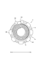
前側環状部12の上端部には、図2および図3に示すように、前側環状部12を周方向に分断する前側上端開口部12Aがやや右方向に開口して設けられており、前側上端開口部12Aを周方向に広げることで前側環状部12は拡径変形可能となっている。
前側上端開口部12Aの左右方向の幅寸法は、前側環状部12が自然状態の場合には、充電ケーブルWの外径寸法よりもやや小さくなっており、前側環状部12が弾性的に拡径変形することで、充電ケーブルWの外径よりも大きくなるように設定されている。したがって、前側環状部12は、拡径変形することで、充電ケーブルWを前側環状部12内に前側上端開口部12Aを通して挿入することができるようになっている。
また、前側環状部12の前端外周面には、径方向外側に向けて突出する複数の突出片(「突出部」の一例)12Bが設けられている。複数の突出片12Bは、前側上端開口部12Aの一方の端部から他方の端部まで、前側環状部12の前端外周面に全周に亘ってほぼ等間隔に形成されている。
後側環状部13は、図3から図5に示すように、充電ケーブルWの外周面を周方向に覆うようにして充電ケーブルWの外径寸法とほぼ同じ内径の略円筒状に形成されており、後側環状部13の上端から左側端部の間には、後側環状部13を周方向に分断する後側上端開口部13Aが左斜め上方に開口して設けられている。後側環状部13は、前側環状部12と同様に、後側上端開口部13Aを周方向に広げることで弾性的に拡径変形するようになっており、後側環状部13が自然状態の場合、後側上端開口部13Aは、充電ケーブルWの外径寸法よりもやや小さくなっている。そして、後側環状部13が拡径変形すると、後側上端開口部13Aは、充電ケーブルWの外径寸法よりも大きくなるように設定されている。
したがって、後側環状部13は、拡径変形することで、前側環状部12と同様に、充電ケーブルWを後側環状部13内に後側上端開口部13Aを通して挿入することができるようになっており、後側環状部13内に充電ケーブルWが挿入されると、後側環状部13内に充電ケーブルWが適合して嵌合されるようになっている。
変形抑制部14は、前側環状部12の後端縁および後側環状部13の前端縁に連設されており、径方向外側の端部を1頂点とする断面略三角形状の弾性変形可能な線形部15によって形成されている。
線形部15は、前側環状部12の後端縁から後側環状部13の前端縁まで後方に向かうほど徐々に小径となる右巻きの螺旋状に形成されており、前後に隣り合う線形部15間の隙間寸法は、線形部15の前後方向の幅寸法とほぼ同じ寸法に設定されている。
したがって、変形抑制部14は、前側環状部12および後側環状部13内に充電ケーブルWを挿入すると共に、線形部15を充電ケーブルWに対して巻き付けることで、図9および図10に示すように、ゴムブッシュ50から後方に引き出された充電ケーブルWを変形抑制部14の軸心に配置することができる。
これにより、充電ケーブルWを前側環状部12および後側環状部13内に挿入すると共に、充電ケーブルWを変形抑制部14内に挿入することで、充電ケーブルWをケーブル変形抑制部材11によって直線状に支持することができる。
そして、例えば、充電ケーブルWが引っ張られるなどして曲げられる場合には、図11に示すように、変形抑制部14において前後に隣り合う線形部15の内周縁部15A同士が当接し、ゴムブッシュ50から引き出された充電ケーブルWが小径に曲げられることを抑制することができるようになっている。
なお、ケーブル変形抑制部材11における変形抑制部14の左右方向両端部14Aは、図3および図4に示すように、変形抑制部14の上端部や下端部のように変形抑制部14の軸心αに対して傾斜した形態となっておらず、変形抑制部14の軸心αに対して上下方向に直交する構成となっている。つまり、ケーブル変形抑制部材11の変形抑制部14は、螺旋状に形成されているものの、上下方向に型開きする図示しない成形金型によって容易に成形することができるようになっている。
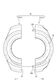
一方、固定部材20は、図6から図8に示すように、個別に設けられた半筒形をなす左右一対の半割固定部材21を有しており、一対の半割固定部材21のうち、右側に配される右側半割固定部材21Rに対して左側に配される左側半割固定部材21Lを左方から重ね合わせ、図1に示すように、複数箇所(本実施形態では2箇所)を固定ねじBによってねじ止めすることにより、略円筒状に組み立てられるようになっている。
一対の半割固定部材21において互いに突き合わせる一方の突き合わせ面22(本実施形態では、右側半割固定部材21Rの突き合わせ面22)には、図6および図9に示すように、固定ねじBによってねじ止めする部分の前後両側に複数(本実施形態では2つ)の位置決め孔22Aが設けられ、他方の突き合わせ面22(本実施形態では、左側半割固定部材21Lの突き合わせ面22)には、図7および図8に示すように、位置決め孔22Aにそれぞれ嵌合可能な複数(本実施形態では2つ)の位置決めピン22Bが設けられている。各位置決め孔22Aと各位置決めピン22Bとは、一対の半割固定部材21を互いに組み付ける際に、凹凸嵌合させることで、突き合わせ面22同士が位置ずれすることを防ぐようになっている。
固定部材20の内部には、図9に示すように、前から順番に、ハウジング31における後側下端部31Aが適合して嵌合される前側嵌合部23、ゴムブッシュ50が適合して嵌合される中央嵌合部24、ケーブル変形抑制部材11における前側環状部12が適合して嵌合される後側嵌合部25が設けられており、右側半割固定部材21Rに各部材31A,50,12の右側半分が嵌合され、左側半割固定部材21Lに各部材31A,50,12の左側半分が嵌合されるようになっている。
各半割固定部材21における前側嵌合部23と中央嵌合部24との間の内周面には、図6、図7および図9に示すように、径方向内側に向かって張り出す位置決め片26が周方向に連続した形態で周設されており、この位置決め片26は、前側嵌合部23内にハウジング31の後側下端部31Aが嵌合され、中央嵌合部24内にゴムブッシュ50が嵌合された際に、ハウジング31とゴムブッシュ50との間の隙間に嵌まり込むようになっている。したがって、固定部材20が組み立てられると、固定部材20内において位置決め片26が全周に亘って構成され、ハウジング31およびゴムブッシュ50に対して固定部材20を前後方向に位置決めすることができるようなっている。
後側嵌合部25は、図6、図7および図9に示すように、前半分が後半分に比べて拡径された突出片収容部25Aとされている。突出片収容部25Aは、各半割固定部材21の内面に半周に亘って周設されており、突出片収容部25Aに前側環状部12の突出片12Bが収容されると、突出片12Bの後面と突出片収容部25Aの後側内面25Bとが係止することで、内部にゴムブッシュ50が嵌合した前側環状部12を固定部材20に対して前後方向に位置決めする。
したがって、図9に示すように、右側半割固定部材21Rに対して、各部材31A,50,12の右側半分を嵌合させた後、図10に示すように、左側半割固定部材21Lを組み付け、固定ねじBによってねじ止めすることにより、充電用コネクタ30の後側下端部に外装部材10を位置決めした状態で固定することができるようになっている。
本実施形態は、以上のような構成であって、続いて、充電用コネクタ30に対する外装部材10の組み付け手順を簡単に説明すると共に、その作用および効果について説明する。
充電用コネクタ30に対して外装部材10を組み付けるには、まず、充電用コネクタ30のゴムブッシュ50から引き出された充電ケーブルWに対してケーブル変形抑制部材11を組み付ける。
ここで、仮に、円筒状のケーブル変形抑制部材に開口部が設けられていない場合には、充電ケーブルに対してケーブル変形抑制部材を側方から組み付けることができない。したがって、このような場合には、充電用コネクタを分解して、充電用コネクタから充電ケーブルを取り外し、充電ケーブルをケーブル変形抑制部材に軸方向に挿通させる必要がある。
ところが、本実施形態の外装部材10によると、ケーブル変形抑制部材11の前側環状部12には前側上端開口部12Aが設けられ、後側環状部13には後側上端開口部13Aが設けられ、変形抑制部14は、螺旋状に形成されている。
したがって、まず、前側環状部12を拡径変形させて前側上端開口部12Aを通して前側環状部12内に充電ケーブルWを挿入する。次に、変形抑制部14の線形部15を充電ケーブルWに巻き付けるようにして変形抑制部14内に充電ケーブルWを挿通した状態に配し、最後に後側環状部13を拡径変形させて充電ケーブルWを、後側上端開口部13Aを通して後側環状部13内に挿入することで、充電ケーブルWに対してケーブル変形抑制部材11を組み付けることができる。すなわち、本実施形態によると、充電ケーブルWに対してケーブル変形抑制部材11を側方から組み付けることができるようになっている。
次に、前側環状部12内にゴムブッシュ50の後端部を挿入するようにして前側環状部12とゴムブッシュ50とを前後方向に嵌合させ、前側環状部12およびゴムブッシュ50に対して固定部材20を組み付ける。
固定部材20の組み付け過程では、例えば、まず、右側半割固定部材21Rにおいて、ハウジング31とゴムブッシュ50との間の隙間に位置決め片26が嵌まり込むように前側嵌合部23内にハウジング31の後側下端部31Aを嵌合させると共に、中央嵌合部24内にゴムブッシュ50を嵌合させる。また、このとき、前側環状部12の内部にゴムブッシュ50を嵌合させた状態で、前側環状部12の突出片12Bを突出片収容部25A内に収容するようにして前側環状部12を後側嵌合部25内に嵌合させる。
これにより、図9に示すように、ハウジング31およびゴムブッシュ50に対して固定部材20を前後方向に位置決めすることができる共に、固定部材20に対して前側環状部12が前後方向に位置決めすることができる。
そして、最後に、図10に示すように、右側半割固定部材21Rに対して左側半割固定部材21Lを組み付け、図1に示すように、固定ねじBによってねじ止めする。これにより、外装部材10が充電用コネクタ30に保持され、充電用コネクタ30の後側下端部31Aに外装部材10を前後方向に位置決めした状態に固定することができる。
以上のように、本実施形態によると、ケーブル変形抑制部材11の前側環状部12と後側環状部13とに上端開口部12A,13Aを設けると共に、変形抑制部14を螺旋状に形成することで、充電用コネクタ30が完成した後であっても、外装部材10を取り付けることができる。すなわち、外装部材10を充電用コネクタ30に対して予め取り付けてゴムブッシュ50を補強することができることはもちろん、ゴムブッシュ50が破損した場合においても、外装部材10を後付けすることで、充電用コネクタ30から充電ケーブルWが引き出された部分を補強し、充電ケーブルWが破損することを抑制することができる。これにより、作業が煩雑になること抑制しつつ、充電ケーブルWが破損することを抑制することができる。
また、充電用コネクタ30に対して外装部材10が装着されることで、充電ケーブルWが曲げられる場合に、充電ケーブルWが小径に曲げられることを抑制し、電線が損傷することをさらに抑制することができる。
また、本実施形態によると、固定部材20の位置決め片26と、突出片収容部25Aの後側内面25Bとによって、ゴムブッシュ50とケーブル変形抑制部材11の前側環状部12とを嵌合状態のまま前後方向両側から係止しているから、外装部材10が後方に引っ張られたり、充電ケーブルWが曲げられたりした際に外装部材10が前後方向に位置ずれすることを確実に防ぐことができる。これにより、外装部材10が位置ずれすることに起因して、充電ケーブルWが意図しない部分において曲がって破損してしまうことを防ぐことができる。
<他の実施形態>
本明細書で開示される技術は上記記述及び図面によって説明した実施形態に限定されるものではなく、例えば次のような種々の態様も含まれる。
本明細書で開示される技術は上記記述及び図面によって説明した実施形態に限定されるものではなく、例えば次のような種々の態様も含まれる。
(1)上記実施形態では、ケーブル変形抑制部材11の変形抑制部14を右巻きの螺旋状に構成した。しかしながら、これに限らず、変形抑制部を左巻きの螺旋状に構成してもよい。
(2)上記実施形態では、変形抑制部14の線形部15を断面略三角形状に構成した。しかしながら、これに限らず、線形部を断面略矩形状や断面略円形状に構成してもよい。
(3)上記実施形態では、固定部材20を一対の半割固定部材21をそれぞれ個別に設けた構成にした。しかしながら、これに限らず、一対の半割固定部材をヒンジなどによって連結した構成にしてもよい。
(4)上記実施形態では、一対の半割固定部材21の突き合わせ面22のうち、一方の半割固定部材21(右側半割固定部材21R)の突き合わせ面22に位置決め孔22Aを設け、他方の半割固定部材21(左側半割固定部材21L)の突き合わせ面22に位置決めピン22Bを設けた構成にした。しかしながら、これに限らず、一方の半割固定部材の突き合わせ面に位置決め孔と位置決めピンを設け、他方の半割固定部材の突き合わせ面にこれとそれぞれ嵌合可能な位置決めピンと位置決め孔を設けた構成にしてもよい。
10:外装部材
11:ケーブル変形抑制部材(「電線変形抑制部材」の一例)
12:前側環状部(「環状部」の一例)
12B:突出片(「突出部」の一例)
13:後側環状部(「環状部」の一例)
14:変形抑制部
20:固定部材
25B:突出片収容部の後側内面(「位置決め部」の一例)
26:位置決め片(「位置決め部」の一例)
30:充電用コネクタ
31:ハウジング(「筐体」の一例)
50:ゴムブッシュ(「電線引出部」の一例)
W:充電ケーブル(「電線」の一例)
11:ケーブル変形抑制部材(「電線変形抑制部材」の一例)
12:前側環状部(「環状部」の一例)
12B:突出片(「突出部」の一例)
13:後側環状部(「環状部」の一例)
14:変形抑制部
20:固定部材
25B:突出片収容部の後側内面(「位置決め部」の一例)
26:位置決め片(「位置決め部」の一例)
30:充電用コネクタ
31:ハウジング(「筐体」の一例)
50:ゴムブッシュ(「電線引出部」の一例)
W:充電ケーブル(「電線」の一例)
Claims (4)
- 筐体から電線が引き出される電線引出部に組み付けられる合成樹脂製の外装部材であって、
前記電線引出部から外部に引き出される前記電線の外周面に沿って設けられ、前記電線の曲がりを抑制する電線変形抑制部材を有しており、
前記電線変形抑制部材における前記電線の延び方向の両端部には、前記電線の外周面を周方向に覆うように環状をなし、弾性的に拡径変形可能に設けられた環状部がそれぞれ配されており、
前記環状部には、自然状態では前記電線の外径寸法よりも小さく、前記環状部が拡径変形することで前記電線を径方向に挿入可能に前記電線の外径寸法よりも大きくなる開口部が設けられている外装部材。 - 前記電線変形抑制部材は、一方の前記環状部と他方の前記環状部との間に連なって設けられ、前記電線の外周面を螺旋状に覆うように弾性変形可能な変形抑制部を備えている請求項1に記載の外装部材。
- 前記筐体は、車両に搭載されたバッテリ装置を充電するための充電用コネクタのグリップ部分を構成するハウジングであり、
前記電線引出部は、前記ハウジングに装着されたゴム材からなる円筒状のゴムブッシュであり、
前記環状部のうち前記電線引出部側である前側環状部には、前記ゴムブッシュが内部に嵌合可能とされており、
前記前側環状部と前記ゴムブッシュとには、前記前側環状部と前記ゴムブッシュとを嵌合状態に固定する固定部材が設けられている請求項1または請求項2に記載の外装部材。 - 前記固定部材は、前記前側環状部の外周面に設けられた突出部と、前記ゴムブッシュとを嵌合状態に固定するように前記電線の延び方向の両側に配される位置決め部を有している請求項3に記載の外装部材。
Applications Claiming Priority (2)
| Application Number | Priority Date | Filing Date | Title |
|---|---|---|---|
| JP2016126393A JP2018005982A (ja) | 2016-06-27 | 2016-06-27 | 外装部材 |
| JP2016-126393 | 2016-06-27 |
Publications (1)
| Publication Number | Publication Date |
|---|---|
| WO2018003422A1 true WO2018003422A1 (ja) | 2018-01-04 |
Family
ID=60786298
Family Applications (1)
| Application Number | Title | Priority Date | Filing Date |
|---|---|---|---|
| PCT/JP2017/020914 Ceased WO2018003422A1 (ja) | 2016-06-27 | 2017-06-06 | 外装部材 |
Country Status (2)
| Country | Link |
|---|---|
| JP (1) | JP2018005982A (ja) |
| WO (1) | WO2018003422A1 (ja) |
Cited By (1)
| Publication number | Priority date | Publication date | Assignee | Title |
|---|---|---|---|---|
| CN114447689A (zh) * | 2022-02-17 | 2022-05-06 | 王全伟 | 一种数据连接线的制备方法及数据连接线 |
Citations (5)
| Publication number | Priority date | Publication date | Assignee | Title |
|---|---|---|---|---|
| JPS63111780U (ja) * | 1987-01-12 | 1988-07-18 | ||
| JPH08162208A (ja) * | 1994-12-01 | 1996-06-21 | Yazaki Corp | 給電側コネクタ |
| JP2010070024A (ja) * | 2008-09-18 | 2010-04-02 | Hitachi Automotive Systems Ltd | パワーステアリング装置及びこれに用いるパワーステアリング装置用ハーネス、並びにパワーステアリング装置の製造方法。 |
| JP2010287453A (ja) * | 2009-06-12 | 2010-12-24 | Kayaba Ind Co Ltd | ハーネス取出構造 |
| JP2012195214A (ja) * | 2011-03-17 | 2012-10-11 | Sumitomo Wiring Syst Ltd | 電線保持部材 |
-
2016
- 2016-06-27 JP JP2016126393A patent/JP2018005982A/ja active Pending
-
2017
- 2017-06-06 WO PCT/JP2017/020914 patent/WO2018003422A1/ja not_active Ceased
Patent Citations (5)
| Publication number | Priority date | Publication date | Assignee | Title |
|---|---|---|---|---|
| JPS63111780U (ja) * | 1987-01-12 | 1988-07-18 | ||
| JPH08162208A (ja) * | 1994-12-01 | 1996-06-21 | Yazaki Corp | 給電側コネクタ |
| JP2010070024A (ja) * | 2008-09-18 | 2010-04-02 | Hitachi Automotive Systems Ltd | パワーステアリング装置及びこれに用いるパワーステアリング装置用ハーネス、並びにパワーステアリング装置の製造方法。 |
| JP2010287453A (ja) * | 2009-06-12 | 2010-12-24 | Kayaba Ind Co Ltd | ハーネス取出構造 |
| JP2012195214A (ja) * | 2011-03-17 | 2012-10-11 | Sumitomo Wiring Syst Ltd | 電線保持部材 |
Cited By (1)
| Publication number | Priority date | Publication date | Assignee | Title |
|---|---|---|---|---|
| CN114447689A (zh) * | 2022-02-17 | 2022-05-06 | 王全伟 | 一种数据连接线的制备方法及数据连接线 |
Also Published As
| Publication number | Publication date |
|---|---|
| JP2018005982A (ja) | 2018-01-11 |
Similar Documents
| Publication | Publication Date | Title |
|---|---|---|
| US20150263495A1 (en) | Grommets and wire harnesses | |
| US10734750B2 (en) | Closing-body holding structure and electric wire with connector | |
| JP6329071B2 (ja) | 同軸円形差込みコネクタ | |
| EP2290760B1 (en) | Plug detachment prevention structure | |
| CN103250304B (zh) | 电缆接口 | |
| CN106199846A (zh) | 一种光纤连接器插头 | |
| US8356947B2 (en) | Optical connector | |
| JP5910832B2 (ja) | ケーブル保持装置 | |
| US10586630B2 (en) | Wire harness | |
| WO2018003422A1 (ja) | 外装部材 | |
| JP6392697B2 (ja) | 充電コネクタ | |
| JP6412649B2 (ja) | ケーブルリール | |
| CN105684228B (zh) | 连接器 | |
| EP0500012B1 (fr) | Procédé de réalisation d'un adaptateur de fréquence | |
| KR101478923B1 (ko) | 퀵 커넥터 | |
| JP6319662B2 (ja) | ノイズフィルタ | |
| JP6616875B1 (ja) | ケーブルグランド | |
| JP6568287B1 (ja) | 取付部材 | |
| JP6482382B2 (ja) | ワイヤーハーネス用プロテクタ | |
| KR200443657Y1 (ko) | 와이어 하네스 프로텍터 | |
| JP6090096B2 (ja) | グロメット及びグロメット付ワイヤーハーネス | |
| JP3218791U (ja) | コネクタ抜け防止具 | |
| JP7151584B2 (ja) | グロメット | |
| CN112510409B (zh) | 连接器 | |
| CN121149732A (zh) | 充电枪壳体、充电枪壳体的安装方法、充电枪及充电设备 |
Legal Events
| Date | Code | Title | Description |
|---|---|---|---|
| 121 | Ep: the epo has been informed by wipo that ep was designated in this application |
Ref document number: 17819787 Country of ref document: EP Kind code of ref document: A1 |
|
| NENP | Non-entry into the national phase |
Ref country code: DE |
|
| 122 | Ep: pct application non-entry in european phase |
Ref document number: 17819787 Country of ref document: EP Kind code of ref document: A1 |