WO2018003392A1 - Link mechanism - Google Patents
Link mechanism Download PDFInfo
- Publication number
- WO2018003392A1 WO2018003392A1 PCT/JP2017/020392 JP2017020392W WO2018003392A1 WO 2018003392 A1 WO2018003392 A1 WO 2018003392A1 JP 2017020392 W JP2017020392 W JP 2017020392W WO 2018003392 A1 WO2018003392 A1 WO 2018003392A1
- Authority
- WO
- WIPO (PCT)
- Prior art keywords
- link member
- air
- link
- door
- opening
- Prior art date
Links
Images

Classifications
-
- B—PERFORMING OPERATIONS; TRANSPORTING
- B60—VEHICLES IN GENERAL
- B60H—ARRANGEMENTS OF HEATING, COOLING, VENTILATING OR OTHER AIR-TREATING DEVICES SPECIALLY ADAPTED FOR PASSENGER OR GOODS SPACES OF VEHICLES
- B60H1/00—Heating, cooling or ventilating [HVAC] devices
- B60H1/00642—Control systems or circuits; Control members or indication devices for heating, cooling or ventilating devices
- B60H1/00814—Control systems or circuits characterised by their output, for controlling particular components of the heating, cooling or ventilating installation
- B60H1/00821—Control systems or circuits characterised by their output, for controlling particular components of the heating, cooling or ventilating installation the components being ventilating, air admitting or air distributing devices
- B60H1/00835—Damper doors, e.g. position control
- B60H1/00857—Damper doors, e.g. position control characterised by the means connecting the initiating means, e.g. control lever, to the damper door
-
- B—PERFORMING OPERATIONS; TRANSPORTING
- B60—VEHICLES IN GENERAL
- B60H—ARRANGEMENTS OF HEATING, COOLING, VENTILATING OR OTHER AIR-TREATING DEVICES SPECIALLY ADAPTED FOR PASSENGER OR GOODS SPACES OF VEHICLES
- B60H1/00—Heating, cooling or ventilating [HVAC] devices
- B60H1/00642—Control systems or circuits; Control members or indication devices for heating, cooling or ventilating devices
- B60H1/00664—Construction or arrangement of damper doors
-
- B—PERFORMING OPERATIONS; TRANSPORTING
- B60—VEHICLES IN GENERAL
- B60H—ARRANGEMENTS OF HEATING, COOLING, VENTILATING OR OTHER AIR-TREATING DEVICES SPECIALLY ADAPTED FOR PASSENGER OR GOODS SPACES OF VEHICLES
- B60H1/00—Heating, cooling or ventilating [HVAC] devices
- B60H1/02—Heating, cooling or ventilating [HVAC] devices the heat being derived from the propulsion plant
- B60H1/04—Heating, cooling or ventilating [HVAC] devices the heat being derived from the propulsion plant from cooling liquid of the plant
- B60H1/08—Heating, cooling or ventilating [HVAC] devices the heat being derived from the propulsion plant from cooling liquid of the plant from other radiator than main radiator
- B60H1/10—Heating, cooling or ventilating [HVAC] devices the heat being derived from the propulsion plant from cooling liquid of the plant from other radiator than main radiator the other radiator being situated in a duct capable of being connected to atmosphere outside vehicle
- B60H1/12—Heating, cooling or ventilating [HVAC] devices the heat being derived from the propulsion plant from cooling liquid of the plant from other radiator than main radiator the other radiator being situated in a duct capable of being connected to atmosphere outside vehicle using an air blower
-
- E—FIXED CONSTRUCTIONS
- E05—LOCKS; KEYS; WINDOW OR DOOR FITTINGS; SAFES
- E05F—DEVICES FOR MOVING WINGS INTO OPEN OR CLOSED POSITION; CHECKS FOR WINGS; WING FITTINGS NOT OTHERWISE PROVIDED FOR, CONCERNED WITH THE FUNCTIONING OF THE WING
- E05F15/00—Power-operated mechanisms for wings
- E05F15/60—Power-operated mechanisms for wings using electrical actuators
- E05F15/603—Power-operated mechanisms for wings using electrical actuators using rotary electromotors
- E05F15/611—Power-operated mechanisms for wings using electrical actuators using rotary electromotors for swinging wings
- E05F15/616—Power-operated mechanisms for wings using electrical actuators using rotary electromotors for swinging wings operated by push-pull mechanisms
-
- E—FIXED CONSTRUCTIONS
- E05—LOCKS; KEYS; WINDOW OR DOOR FITTINGS; SAFES
- E05Y—INDEXING SCHEME RELATING TO HINGES OR OTHER SUSPENSION DEVICES FOR DOORS, WINDOWS OR WINGS AND DEVICES FOR MOVING WINGS INTO OPEN OR CLOSED POSITION, CHECKS FOR WINGS AND WING FITTINGS NOT OTHERWISE PROVIDED FOR, CONCERNED WITH THE FUNCTIONING OF THE WING
- E05Y2900/00—Application of doors, windows, wings or fittings thereof
- E05Y2900/50—Application of doors, windows, wings or fittings thereof for vehicles
- E05Y2900/53—Application of doors, windows, wings or fittings thereof for vehicles characterised by the type of wing
- E05Y2900/531—Doors
Definitions
- the present disclosure relates to a link mechanism for opening and closing an open / close door provided at a blow-out port for blowing air for air conditioning into a vehicle interior.
- the vehicle air conditioner includes a plurality of air outlets that blow air conditioning air for adjusting the temperature in the vehicle interior from an air passage in the air conditioning case into the vehicle interior, and a plurality of opening and closing doors that respectively open and close these air outlets,
- a link mechanism connected to the plurality of opening / closing doors and a motor for opening / closing the opening / closing doors via the link mechanism are provided.
- this type of link mechanism there is a link mechanism described in Patent Document 1.
- the link mechanism described in Patent Document 1 includes a mode link, a first link member, and a second link member.
- the mode link is formed in a disk shape.
- a guide groove is formed in the mode link.
- a pin inserted into the guide groove of the mode link is formed at one end of the first link member.
- the other end of the first link member is connected to the rotation shaft of the open / close door via the second link member.
- the first link member has a rotation shaft that is rotatably supported with respect to the air conditioning case.
- the rotation shaft of the first link member is not fixed to the air conditioning case and is inserted to such an extent that the insertion hole formed in the air conditioning case is prevented from coming off. It has only been done. Therefore, the posture of the first link member may be tilted by an external force applied to the first link member from the opening / closing door via the second link member.
- the open / close door when the open / close door is held at a predetermined opening, the open / close door receives wind pressure based on the flow of air-conditioning air blown from the air outlet. That is, the open / close door receives a wind pressure in a direction from the air conditioning case to the vehicle interior, in other words, a wind pressure in a direction in which the open / close door is fully closed.
- the external force acts on the open / close door
- the external force acts on the first link member via the second link member.
- An object of the present disclosure is to provide a link mechanism capable of improving the positioning accuracy of an opening / closing door.
- the link mechanism includes a first link member, a second link member, and a third link member.
- the first link member is connected to the motor and rotates by driving the motor.
- the second link member is connected to an open / close door that opens and closes a blow-out port that blows air for air conditioning for adjusting the temperature in the vehicle interior into the vehicle interior.
- the third link member has a rotation shaft supported by the fixed member, and connects the first link member and the second link member.
- the first link member is formed with a protruding portion that protrudes toward the third link member.
- the link mechanism includes a first link member, a second link member, a third link member, and a link cover.
- the first link member is connected to the motor and rotates by driving the motor.
- the second link member is connected to an open / close door that opens and closes a blow-out port that blows air for air conditioning for adjusting the temperature in the vehicle interior into the vehicle interior.
- the third link member has a rotation shaft supported by the fixed member, and connects the first link member and the second link member.
- the link cover is arrange
- the link cover is formed with a protruding portion that protrudes toward the third link member.
- the third link member is Since it contacts the protrusion or the protrusion of the link cover, the inclination of the third link member can be suppressed. As a result, since the displacement of the second link member can be suppressed, the positioning accuracy of the open / close door can be improved.
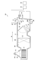
- FIG. 1 is a diagram schematically showing a schematic configuration of a vehicle air conditioner.
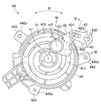
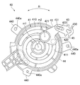
- Drawing 2 is a front view showing the front structure of the link mechanism of an embodiment.
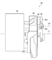
- FIG. 3 is a side view showing a side structure of the link mechanism of the embodiment.
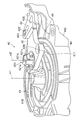
- FIG. 4 is a perspective view showing a perspective structure of the link mechanism of the embodiment.
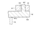
- FIG. 5 is a cross-sectional view showing a cross-sectional structure along the line VV in FIG. 6 is a cross-sectional view showing a cross-sectional structure taken along line VI-VI in FIG.
- FIG. 7 is a cross-sectional view showing a cross-sectional structure of a link mechanism of a comparative example.
- FIG. 8 is a front view showing a front structure of a link mechanism of another embodiment.
- the vehicle air conditioner 10 includes an air conditioning case 20 and an air conditioning unit 30.
- the vehicle air conditioner 10 is provided inside an instrument panel of the vehicle.
- An air passage 21 is formed in the air conditioning case 20.
- the air passage 21 is a passage that guides air for air conditioning into the passenger compartment.
- the air for air conditioning is air for adjusting the temperature in the passenger compartment.
- air flows in the direction indicated by the arrow W in the drawing.
- An outside air inlet 22 and an inside air inlet 23 are formed in a portion of the air conditioning case 20 on the upstream side in the air flow direction W as a portion for taking air into the air passage 21 from the outside of the air conditioning case 20.
- the outside air inlet 22 is a part that takes outside air, which is air outside the passenger compartment, into the air passage 21.
- the inside air inlet 23 is a portion that takes in the inside air, which is the air in the passenger compartment, into the air passage 21.
- a defroster air outlet 24, a face air outlet 25, and a foot air outlet 26 are formed at the downstream side of the air flow direction W in the air conditioning case 20.
- the defroster outlet 24 blows air flowing through the air conditioning case 20 toward the inner surface of the windshield of the vehicle.
- the face outlet 25 blows out air flowing in the air conditioning case 20 toward the driver or the passenger on the passenger seat.
- the foot outlet 26 blows out air flowing in the air conditioning case 20 toward the feet of the driver or the passenger in the passenger seat.
- the air conditioning unit 30 generates air for air conditioning based on the air introduced into the air passage 21 from the outside air inlet 22 or the inside air inlet 23.
- the air conditioning unit 30 includes a blower fan 31, an evaporator 32, and a heater core 33.
- the blower fan 31 is disposed on the downstream side in the air flow direction W of the outside air inlet 22 and the inside air inlet 23.
- the blower fan 31 generates an air flow in the air passage 21 by rotating based on energization.
- the energization amount of the blower fan 31 By adjusting the energization amount of the blower fan 31, the amount of air flowing through the air passage 21, that is, the amount of air conditioning air is adjusted.
- the evaporator 32 is disposed downstream of the blower fan 31 in the air flow direction W.
- the evaporator 32 is a component of a refrigeration cycle (not shown).
- the refrigeration cycle includes an evaporator 32, a compressor, a condenser, and an expansion valve.
- the refrigerant circulates in the order of the compressor, the condenser, the expansion valve, and the evaporator 32.
- the refrigerant is evaporated and vaporized by heat exchange between the refrigerant flowing inside and the air in the air passage 21.
- the evaporator 32 has a function of cooling the air in the air passage 21 using heat of vaporization when the refrigerant is vaporized, and a function of dehumidifying the air in the air passage 21.
- the heater core 33 is disposed downstream of the evaporator 32 in the air flow direction W.
- the heater core 33 is connected to an engine (not shown) through a pipe.
- Engine cooling water circulates between the engine and the heater core 33 via this pipe.
- the heater core 33 heats the air in the air passage 21 using the engine coolant flowing inside as a heat source.
- the air conditioning unit 30 further includes an inside / outside air switching door 34, an air mix door 35, a defroster door 36, a face door 37, a foot door 38, a link mechanism 40, and a motor 50.
- the inside / outside air switching door 34 opens and closes the outside air inlet 22 and the inside air inlet 23.
- the inside / outside air switching door 34 is located at the inside air introduction position indicated by a solid line in the drawing, the outside air inlet 22 is closed and the inside air inlet 23 is opened.
- the vehicle air conditioner 10 is in an inside air circulation mode in which inside air is taken into the air passage 21 from the inside air suction port 23.
- the inside / outside air switching door 34 is located at the outside air introduction position indicated by a broken line in the drawing, the inside air inlet 23 is closed and the outside air inlet 22 is opened.
- the vehicle air conditioner 10 is in an outside air introduction mode for taking in outside air from the outside air inlet 22 into the air passage 21.
- the air mix door 35 adjusts the ratio between the air volume flowing into the heater core 33 and the air volume bypassing the heater core 33. Specifically, the position of the air mix door 35 can be adjusted between a maximum heating position indicated by a solid line in the drawing and a maximum cooling position indicated by a broken line in the drawing. When the position of the air mix door 35 is the maximum heating position, most of the air that has passed through the evaporator 32 passes through the heater core 33, so that the temperature of the air-conditioning air rises most. When the position of the air mix door 35 is the maximum cooling position, most of the air that has passed through the evaporator 32 bypasses the heater core 33.
- the temperature of the air-conditioning air is the lowest.
- the temperature of the air conditioning air is adjusted by adjusting the opening of the air mix door 35 between the maximum heating position and the maximum cooling position.
- the defroster door 36 opens and closes the defroster outlet 24 by rotating around the rotation shaft 360.
- the face door 37 opens and closes the face air outlet 25 by rotating around the rotation shaft 370.
- the foot door 38 opens and closes the foot outlet 26 by rotating around the rotation shaft 380. Therefore, in the vehicle air conditioner 10, the air-conditioning air generated in the air-conditioning case 20 is blown out from the air outlets 24 to 26 corresponding to the opened doors toward the vehicle interior.
- the link mechanism 40 is connected to the rotation shaft 360 of the defroster door 36, the rotation shaft 370 of the face door 37, and the rotation shaft 380 of the foot door 38.
- the motor 50 opens and closes the doors 36 to 38 by rotating the rotary shafts 360, 370, and 380 via the link mechanism 40.
- the motor 50 is a servo motor.
- the defroster door 36 corresponds to an open / close door.
- the link mechanism 40 includes a disk link member 41, an intermediate link member 42, a door link member 43, and a link cover 44.
- the disk link member 41 is formed in a disk shape around the axis m1 in the drawing.
- a rotating shaft of the motor 50 shown in FIG. 3 is connected to the center of the disk link member 41. Based on the drive of the motor 50, the disk link member 41 rotates in the direction indicated by the arrow R around the central axis m1 shown in FIG.
- a guide groove 411 is formed on one side surface 410 of the disk link member 41 in the axial direction.
- the guide groove 411 is formed so as to extend in a curved shape in the circumferential direction of the disk link member 41.
- the disk link member 41 corresponds to the first link member.
- a fitting hole 430 is formed at the tip of the door link member 43.
- the rotation shaft 360 of the defroster door 36 shown in FIG. 1 is fitted into the fitting hole 430.
- the door link member 43 rotates integrally with the defroster door 36.
- an elongated insertion hole 431 is formed at the base end of the door link member 43.
- the door link member 43 corresponds to a second link member.
- a pin 420 and a rotating shaft 421 are formed at one end of the intermediate link member 42.
- the pin 420 extends parallel to the axis m ⁇ b> 1 toward the disk link member 41 and is slidably inserted into the guide groove 411 of the disk link member 41.
- the rotating shaft 421 has three claw portions 421a to 421c. These claw portions 421a to 421c are attached to the air conditioning case 20 by being inserted into insertion holes (not shown) formed in the air conditioning case 20. With the attachment structure of the claw portions 421a to 421c, the intermediate link member 42 is supported to the air conditioning case 20 so as to be rotatable about an axis m2 passing through the center of the rotation shaft 421.
- the air conditioning case 20 corresponds to a fixing member.
- FIG. 5 is a cross-sectional view showing a cross-sectional structure taken along line IV-IV in FIG. As shown in FIG. 5, specifically, the pin 422 is inserted into the insertion hole 431 of the door link member 43 with a predetermined gap.
- the intermediate link member 42 corresponds to a third link member.
- the link cover 44 is disposed so as to cover the periphery of the disk link member 41.
- a plurality of protrusions 440 are formed on the outer peripheral surface of the link cover 44. Insertion holes 440a penetrating in a direction parallel to the axis m1 are formed in the plurality of protrusions 440, respectively.
- the link cover 44 is fastened to the air conditioning case 20 by fastening the link cover 44 to the air conditioning case 20 with bolts inserted into these insertion holes 440a.
- a protruding portion 45 that protrudes toward the intermediate link member 42 is formed in a portion of the link cover 44 that faces the intermediate link member 42.
- the facing surface 45 a that faces the intermediate link member 42 in the protrusion 45 is formed in parallel to the facing surface 423 that faces the disk link member 41 in the intermediate link member 42.
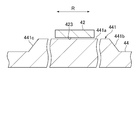
- FIG. 6 shows a cross-sectional structure along the line VI-VI in FIG.
- the side walls 45 b and 45 c of the protrusion 45 in the rotation direction R of the disk link member 41 are formed in a tapered shape.
- the defroster door 36 is held from the fully closed position P1 to a position P2 opened by a predetermined opening degree. Is done.
- the position P2 having the predetermined opening is set to a position inclined by “5 °” from the fully closed position P1, for example.
- an external force in the direction toward the fully closed position P ⁇ b> 1 is applied to the defroster door 36 by the wind pressure based on the air flow passing through the defroster outlet 24 from the air passage 21 acting on the defroster door 36. Due to this external force, the door link member 43 tends to be displaced in the direction indicated by the arrow A shown in FIG. 2, so that the external force in the direction indicated by the arrow A is applied to the end of the intermediate link member 42 on the pin 422 side. Is granted.
- the disk link member 41 is connected to the rotating shaft of the motor 50, the position of the disk link member 41 is fixed. Since the pin 420 of the intermediate link member 42 is inserted into the guide groove 411 of the disk link member 41, the position of the end portion on the pin 420 side of the intermediate link member 42 is fixed.
- the intermediate link member 42 when the intermediate link member 42 is inclined, the intermediate link member 42 contacts the protruding portion 45 of the link cover 44. Therefore, in the case of a structure in which the protrusion 45 is not formed on the link cover 44, the intermediate link member 42 is largely inclined as shown by a two-dot chain line in FIG. 7, whereas the link mechanism 40 of the present embodiment. Then, as shown by a two-dot chain line in FIG. 5, the inclination of the intermediate link member 42 can be suppressed.
- the facing surface 45a facing the intermediate link member 42 in the protruding portion 45 is formed in parallel to the facing surface 423 facing the disk link member 41 in the intermediate link member 42.
- the said embodiment can also be implemented with the following forms.
- the shape of the protrusion part 45 can be changed suitably.
- the tip of the protrusion 45 may be formed in a curved shape.
- the protrusion 45 may be formed in the link cover 44 at least at a portion facing the intermediate link member 42 when the defroster door 36 is held at the position P2 having a predetermined opening. Thereby, the positioning accuracy at the time of hold
- the protrusion 45 is not limited to the link cover 44, and may be formed on the outer edge portion of the side surface 410 of the disk link member 41.
- the protrusion 45 may be formed in the disk link member 41 at least at a portion facing the intermediate link member 42 when the defroster door 36 is held at the position P2 having a predetermined opening degree. Thereby, the positioning accuracy at the time of hold
- the intermediate link member 42 is not limited to the air conditioning case 20 and may be supported by an arbitrary fixing member.
- the shapes of the disk link member 41, the intermediate link member 42, and the door link member 43 can be changed as appropriate.
- the structure of the protrusion part 45 of the said embodiment may be used as a structure for suppressing the inclination of the intermediate link member used for opening and closing of a face door or a foot door.
Landscapes
- Engineering & Computer Science (AREA)
- Physics & Mathematics (AREA)
- Thermal Sciences (AREA)
- Mechanical Engineering (AREA)
- Chemical & Material Sciences (AREA)
- Combustion & Propulsion (AREA)
- Air-Conditioning For Vehicles (AREA)
Abstract
Description
モータ50の駆動に基づき円盤リンク部材41が軸線m1を中心に回転すると、中間リンク部材42のピン420が円盤リンク部材41のガイド溝411に沿って変位する。このピン420の変位に基づいて中間リンク部材42が回転軸421を中心に回転することにより、ドアリンク部材43が変位する。このとき、ドアリンク部材43とデフロスタドア36の回転軸360とが一体的に回転することにより、デフロスタドア36が開閉動作する。 Next, an operation example of the
When the
・突出部45の形状は適宜変更可能である。例えば突出部45の先端部は曲線状に形成されていてもよい。 In addition, the said embodiment can also be implemented with the following forms.
-The shape of the
Claims (6)
- モータ(50)に連結され、前記モータの駆動により回転する第1リンク部材(41)と、
車室内の温度を調整するための空調用空気を車室内に吹き出す吹出口(24)を開閉する開閉ドア(36)に連結される第2リンク部材(43)と、
固定部材(20)に支持される回転軸(421)を有し、前記第1リンク部材及び前記第2リンク部材を連結する第3リンク部材(42)と、を備え、
前記第1リンク部材には、
前記第3リンク部材に向かって突出する突出部(45)が形成されている
リンク機構。 A first link member (41) coupled to the motor (50) and rotated by driving of the motor;
A second link member (43) connected to an open / close door (36) for opening and closing an air outlet (24) for blowing air conditioning air for adjusting the temperature in the vehicle interior into the vehicle interior;
A third link member (42) having a rotation shaft (421) supported by the fixing member (20) and connecting the first link member and the second link member;
In the first link member,
A projecting portion (45) projecting toward the third link member is formed. - 前記開閉ドアは、
全閉位置から所定開度だけ開いた位置で保持されるものであり、
前記突出部は、
前記開閉ドアを前記所定開度の位置で保持する際に前記第1リンク部材において前記第3リンク部材に対向する部分に形成されている
請求項1に記載のリンク機構。 The open / close door is
It is held at a position opened by a predetermined opening from the fully closed position,
The protrusion is
The link mechanism according to claim 1, wherein the link mechanism is formed in a portion of the first link member that faces the third link member when the opening / closing door is held at the position of the predetermined opening degree. - モータ(50)に連結され、前記モータの駆動により回転する第1リンク部材(41)と、
車室内の温度を調整するための空調用空気を車室内に吹き出す吹出口(24)を開閉する開閉ドア(36)に連結される第2リンク部材(43)と、
固定部材(20)に支持される回転軸(421)を有し、前記第1リンク部材及び前記第2リンク部材を連結する第3リンク部材(42)と、
前記第1リンク部材の周囲を覆うように配置されるリンクカバー(44)と、を備え、
前記リンクカバーには、
前記第3リンク部材に向かって突出する突出部(45)が形成されている
リンク機構。 A first link member (41) coupled to the motor (50) and rotated by driving of the motor;
A second link member (43) connected to an open / close door (36) for opening and closing an air outlet (24) for blowing air conditioning air for adjusting the temperature in the vehicle interior into the vehicle interior;
A third link member (42) having a rotation shaft (421) supported by the fixing member (20) and connecting the first link member and the second link member;
A link cover (44) disposed to cover the periphery of the first link member,
The link cover includes
A projecting portion (45) projecting toward the third link member is formed. - 前記開閉ドアは、
全閉位置から所定開度だけ開いた位置で保持されるものであり、
前記突出部は、
前記開閉ドアを前記所定開度で保持させる際に前記リンクカバーにおいて前記第3リンク部材に対向する部分に形成されている
請求項3に記載のリンク機構。 The open / close door is
It is held at a position opened by a predetermined opening from the fully closed position,
The protrusion is
The link mechanism according to claim 3, wherein the link cover is formed in a portion of the link cover that faces the third link member when the opening / closing door is held at the predetermined opening degree. - 前記第1リンク部材の回転方向における前記突出部の側壁(441b,441c)は、テーパ状に形成されている
請求項1~4のいずれか一項に記載のリンク機構。 The link mechanism according to any one of claims 1 to 4, wherein a side wall (441b, 441c) of the protrusion in the rotation direction of the first link member is formed in a tapered shape. - 前記突出部において前記第3リンク部材に対向する対向面(441a)は、前記第3リンク部材において前記第1リンク部材に対向する対向面(423)に平行に形成されている
請求項1~5のいずれか一項に記載のリンク機構。 The facing surface (441a) facing the third link member in the protruding portion is formed in parallel to the facing surface (423) facing the first link member in the third link member. The link mechanism according to any one of the above.
Priority Applications (5)
| Application Number | Priority Date | Filing Date | Title |
|---|---|---|---|
| GB1815877.4A GB2564332B (en) | 2016-06-29 | 2017-06-01 | Link mechanism |
| BR112018070837A BR112018070837A2 (en) | 2016-06-29 | 2017-06-01 | binding mechanism. |
| US16/312,312 US10864798B2 (en) | 2016-06-29 | 2017-06-01 | Link mechanism |
| CA3029214A CA3029214C (en) | 2016-06-29 | 2017-06-01 | Link mechanism for a vehicle air conditioner |
| CN201780036330.8A CN109311365B (en) | 2016-06-29 | 2017-06-01 | Link mechanism |
Applications Claiming Priority (2)
| Application Number | Priority Date | Filing Date | Title |
|---|---|---|---|
| JP2016128569A JP6658345B2 (en) | 2016-06-29 | 2016-06-29 | Link mechanism |
| JP2016-128569 | 2016-06-29 |
Publications (1)
| Publication Number | Publication Date |
|---|---|
| WO2018003392A1 true WO2018003392A1 (en) | 2018-01-04 |
Family
ID=60786853
Family Applications (1)
| Application Number | Title | Priority Date | Filing Date |
|---|---|---|---|
| PCT/JP2017/020392 WO2018003392A1 (en) | 2016-06-29 | 2017-06-01 | Link mechanism |
Country Status (7)
| Country | Link |
|---|---|
| US (1) | US10864798B2 (en) |
| JP (1) | JP6658345B2 (en) |
| CN (1) | CN109311365B (en) |
| BR (1) | BR112018070837A2 (en) |
| CA (1) | CA3029214C (en) |
| GB (1) | GB2564332B (en) |
| WO (1) | WO2018003392A1 (en) |
Families Citing this family (3)
| Publication number | Priority date | Publication date | Assignee | Title |
|---|---|---|---|---|
| US11125310B2 (en) * | 2016-11-23 | 2021-09-21 | Hanon Systems | Supercircumrotational cam |
| US10821808B2 (en) * | 2018-10-26 | 2020-11-03 | Denso International America, Inc. | Universal mode plate |
| US11660930B2 (en) * | 2019-10-14 | 2023-05-30 | Denso International America, Inc. | Actuator assembly |
Citations (6)
| Publication number | Priority date | Publication date | Assignee | Title |
|---|---|---|---|---|
| JPS63199813U (en) * | 1987-06-15 | 1988-12-22 | ||
| JP2006111119A (en) * | 2004-10-14 | 2006-04-27 | Denso Corp | Air conditioner |
| JP2007147033A (en) * | 2005-11-30 | 2007-06-14 | Denso Corp | Link device |
| JP2007161085A (en) * | 2005-12-14 | 2007-06-28 | Denso Corp | Link device and air conditioner for vehicle |
| JP2008018886A (en) * | 2006-07-14 | 2008-01-31 | Denso Corp | Link mechanism of vehicular air-conditioner |
| JP2015093583A (en) * | 2013-11-12 | 2015-05-18 | 株式会社ヴァレオジャパン | Vehicular air conditioning device |
Family Cites Families (9)
| Publication number | Priority date | Publication date | Assignee | Title |
|---|---|---|---|---|
| JPS60117210U (en) * | 1984-01-19 | 1985-08-08 | カルソニックカンセイ株式会社 | Automotive air conditioner |
| JPH10100644A (en) * | 1996-09-27 | 1998-04-21 | Denso Corp | Air conditioner |
| JP3752792B2 (en) * | 1997-08-06 | 2006-03-08 | 株式会社デンソー | Air conditioner |
| JP2004058941A (en) | 2002-07-31 | 2004-02-26 | Denso Corp | Link member fitting structure |
| US7431639B2 (en) * | 2003-09-17 | 2008-10-07 | Calsonic Kansei Corporation | Vehicle air-conditioning unit, assembly structure of vehicle air-conditioning unit and link module for use therein |
| JP2008037378A (en) | 2006-08-10 | 2008-02-21 | Calsonic Kansei Corp | Door lever structure of air conditioner for vehicle |
| JP2008110721A (en) | 2006-10-31 | 2008-05-15 | Calsonic Kansei Corp | Vehicular air-conditioner |
| JP2013071484A (en) | 2011-09-27 | 2013-04-22 | Keihin Corp | Link structure used for air conditioning apparatus for vehicle |
| CN204641320U (en) * | 2015-05-11 | 2015-09-16 | 安徽江淮汽车股份有限公司 | A kind of automobile air conditioner air outlet mode regulating mechanism |
-
2016
- 2016-06-29 JP JP2016128569A patent/JP6658345B2/en active Active
-
2017
- 2017-06-01 BR BR112018070837A patent/BR112018070837A2/en not_active Application Discontinuation
- 2017-06-01 GB GB1815877.4A patent/GB2564332B/en not_active Expired - Fee Related
- 2017-06-01 WO PCT/JP2017/020392 patent/WO2018003392A1/en active Application Filing
- 2017-06-01 US US16/312,312 patent/US10864798B2/en active Active
- 2017-06-01 CN CN201780036330.8A patent/CN109311365B/en active Active
- 2017-06-01 CA CA3029214A patent/CA3029214C/en active Active
Patent Citations (6)
| Publication number | Priority date | Publication date | Assignee | Title |
|---|---|---|---|---|
| JPS63199813U (en) * | 1987-06-15 | 1988-12-22 | ||
| JP2006111119A (en) * | 2004-10-14 | 2006-04-27 | Denso Corp | Air conditioner |
| JP2007147033A (en) * | 2005-11-30 | 2007-06-14 | Denso Corp | Link device |
| JP2007161085A (en) * | 2005-12-14 | 2007-06-28 | Denso Corp | Link device and air conditioner for vehicle |
| JP2008018886A (en) * | 2006-07-14 | 2008-01-31 | Denso Corp | Link mechanism of vehicular air-conditioner |
| JP2015093583A (en) * | 2013-11-12 | 2015-05-18 | 株式会社ヴァレオジャパン | Vehicular air conditioning device |
Also Published As
| Publication number | Publication date |
|---|---|
| US10864798B2 (en) | 2020-12-15 |
| CA3029214C (en) | 2021-05-18 |
| BR112018070837A2 (en) | 2019-02-05 |
| JP6658345B2 (en) | 2020-03-04 |
| CN109311365B (en) | 2022-01-04 |
| JP2018001855A (en) | 2018-01-11 |
| GB2564332A (en) | 2019-01-09 |
| GB2564332B (en) | 2020-07-08 |
| CN109311365A (en) | 2019-02-05 |
| CA3029214A1 (en) | 2018-01-04 |
| US20190232756A1 (en) | 2019-08-01 |
Similar Documents
| Publication | Publication Date | Title |
|---|---|---|
| US10266030B2 (en) | Air conditioning unit for vehicle | |
| WO2017221460A1 (en) | Air conditioning apparatus | |
| WO2018003392A1 (en) | Link mechanism | |
| US11654745B2 (en) | Air conditioning unit for vehicle | |
| JP7074086B2 (en) | Vehicle air conditioner | |
| JP4380450B2 (en) | Air passage opening and closing device and vehicle air conditioner | |
| JP4618193B2 (en) | Air passage opening and closing device | |
| KR102001998B1 (en) | Air conditioner for vehicle | |
| JP2008143237A (en) | Vehicular air-conditioner | |
| WO2018084259A1 (en) | Air-conditioning unit for vehicular air-conditioning device, and method for manufacturing first air-conditioning unit and second air-conditioning unit | |
| KR20080040492A (en) | Air conditioner for vehicles | |
| WO2016002188A1 (en) | Door member, door device, and vehicle air-conditioning apparatus using same | |
| JP2007168735A (en) | Air passage switching device and inside/outside air switching device of air conditioner for vehicle | |
| JP2008273234A (en) | Air passage opening/closing door | |
| JP2008195213A (en) | Fitting structure of air-conditioning case | |
| JP2009286348A (en) | Air conditioner for vehicle | |
| WO2019181262A1 (en) | Vehicle air conditioning unit | |
| KR101960833B1 (en) | Dual Air Conditioner for Motor Vehicle | |
| JP2009001237A (en) | Air conditioner for vehicle | |
| JP2009119911A (en) | Vehicular air conditioner | |
| JP2010208430A (en) | Link structure of air conditioner for vehicle | |
| JP2005262990A (en) | Vehicular air-conditioner | |
| JP2017159831A (en) | Air conditioner for vehicle | |
| JP2002120538A (en) | Air conditioner | |
| JP2006062612A (en) | Vehicular air-conditioner |
Legal Events
| Date | Code | Title | Description |
|---|---|---|---|
| ENP | Entry into the national phase |
Ref document number: 201815877 Country of ref document: GB Kind code of ref document: A Free format text: PCT FILING DATE = 20170601 |
|
| WWE | Wipo information: entry into national phase |
Ref document number: 1815877.4 Country of ref document: GB |
|
| REG | Reference to national code |
Ref country code: BR Ref legal event code: B01A Ref document number: 112018070837 Country of ref document: BR |
|
| 121 | Ep: the epo has been informed by wipo that ep was designated in this application |
Ref document number: 17819758 Country of ref document: EP Kind code of ref document: A1 |
|
| ENP | Entry into the national phase |
Ref document number: 3029214 Country of ref document: CA |
|
| NENP | Non-entry into the national phase |
Ref country code: DE |
|
| ENP | Entry into the national phase |
Ref document number: 112018070837 Country of ref document: BR Kind code of ref document: A2 Effective date: 20181009 |
|
| 122 | Ep: pct application non-entry in european phase |
Ref document number: 17819758 Country of ref document: EP Kind code of ref document: A1 |