WO2018003311A1 - 超音波内視鏡 - Google Patents
超音波内視鏡 Download PDFInfo
- Publication number
- WO2018003311A1 WO2018003311A1 PCT/JP2017/017858 JP2017017858W WO2018003311A1 WO 2018003311 A1 WO2018003311 A1 WO 2018003311A1 JP 2017017858 W JP2017017858 W JP 2017017858W WO 2018003311 A1 WO2018003311 A1 WO 2018003311A1
- Authority
- WO
- WIPO (PCT)
- Prior art keywords
- ultrasonic
- ground
- material layer
- backing material
- wiring
- Prior art date
Links
- 239000000463 material Substances 0.000 claims abstract description 140
- 239000000758 substrate Substances 0.000 claims description 31
- 229910000679 solder Inorganic materials 0.000 claims description 20
- 238000002604 ultrasonography Methods 0.000 claims description 15
- BQCADISMDOOEFD-UHFFFAOYSA-N Silver Chemical compound [Ag] BQCADISMDOOEFD-UHFFFAOYSA-N 0.000 claims description 8
- 229910052709 silver Inorganic materials 0.000 claims description 8
- 239000004332 silver Substances 0.000 claims description 8
- 238000002844 melting Methods 0.000 claims description 7
- 230000008018 melting Effects 0.000 claims description 7
- 229910052751 metal Inorganic materials 0.000 claims description 6
- 239000002184 metal Substances 0.000 claims description 6
- RYGMFSIKBFXOCR-UHFFFAOYSA-N Copper Chemical compound [Cu] RYGMFSIKBFXOCR-UHFFFAOYSA-N 0.000 description 128
- 239000011889 copper foil Substances 0.000 description 118
- 238000003780 insertion Methods 0.000 description 29
- 230000037431 insertion Effects 0.000 description 29
- 230000017525 heat dissipation Effects 0.000 description 24
- XLYOFNOQVPJJNP-UHFFFAOYSA-N water Substances O XLYOFNOQVPJJNP-UHFFFAOYSA-N 0.000 description 24
- 238000005286 illumination Methods 0.000 description 13
- 238000003384 imaging method Methods 0.000 description 12
- 238000004140 cleaning Methods 0.000 description 11
- 239000000945 filler Substances 0.000 description 11
- 238000000034 method Methods 0.000 description 11
- 229910052802 copper Inorganic materials 0.000 description 10
- 239000010949 copper Substances 0.000 description 10
- XUIMIQQOPSSXEZ-UHFFFAOYSA-N Silicon Chemical compound [Si] XUIMIQQOPSSXEZ-UHFFFAOYSA-N 0.000 description 7
- 229910052710 silicon Inorganic materials 0.000 description 7
- 239000010703 silicon Substances 0.000 description 7
- 238000007689 inspection Methods 0.000 description 6
- 238000005452 bending Methods 0.000 description 5
- 239000004020 conductor Substances 0.000 description 5
- 238000003745 diagnosis Methods 0.000 description 5
- 238000010586 diagram Methods 0.000 description 5
- 230000036961 partial effect Effects 0.000 description 5
- 238000012545 processing Methods 0.000 description 5
- 229910052782 aluminium Inorganic materials 0.000 description 4
- XAGFODPZIPBFFR-UHFFFAOYSA-N aluminium Chemical compound [Al] XAGFODPZIPBFFR-UHFFFAOYSA-N 0.000 description 4
- 230000005540 biological transmission Effects 0.000 description 4
- 239000011888 foil Substances 0.000 description 4
- 230000002829 reductive effect Effects 0.000 description 4
- 239000011347 resin Substances 0.000 description 4
- 229920005989 resin Polymers 0.000 description 4
- 230000003287 optical effect Effects 0.000 description 3
- 230000000644 propagated effect Effects 0.000 description 3
- 230000005855 radiation Effects 0.000 description 3
- VYPSYNLAJGMNEJ-UHFFFAOYSA-N Silicium dioxide Chemical compound O=[Si]=O VYPSYNLAJGMNEJ-UHFFFAOYSA-N 0.000 description 2
- 239000000919 ceramic Substances 0.000 description 2
- 230000007423 decrease Effects 0.000 description 2
- 238000001514 detection method Methods 0.000 description 2
- 238000002592 echocardiography Methods 0.000 description 2
- 229920001971 elastomer Polymers 0.000 description 2
- 210000000232 gallbladder Anatomy 0.000 description 2
- PCHJSUWPFVWCPO-UHFFFAOYSA-N gold Chemical compound [Au] PCHJSUWPFVWCPO-UHFFFAOYSA-N 0.000 description 2
- 229910052737 gold Inorganic materials 0.000 description 2
- 239000010931 gold Substances 0.000 description 2
- 230000020169 heat generation Effects 0.000 description 2
- 230000006872 improvement Effects 0.000 description 2
- HFGPZNIAWCZYJU-UHFFFAOYSA-N lead zirconate titanate Chemical compound [O-2].[O-2].[O-2].[O-2].[O-2].[Ti+4].[Zr+4].[Pb+2] HFGPZNIAWCZYJU-UHFFFAOYSA-N 0.000 description 2
- 229910052451 lead zirconate titanate Inorganic materials 0.000 description 2
- 210000000496 pancreas Anatomy 0.000 description 2
- 230000002093 peripheral effect Effects 0.000 description 2
- 230000008569 process Effects 0.000 description 2
- 229920002379 silicone rubber Polymers 0.000 description 2
- 238000003860 storage Methods 0.000 description 2
- 239000000126 substance Substances 0.000 description 2
- 229920001875 Ebonite Polymers 0.000 description 1
- 239000002033 PVDF binder Substances 0.000 description 1
- GWEVSGVZZGPLCZ-UHFFFAOYSA-N Titan oxide Chemical compound O=[Ti]=O GWEVSGVZZGPLCZ-UHFFFAOYSA-N 0.000 description 1
- PNEYBMLMFCGWSK-UHFFFAOYSA-N aluminium oxide Inorganic materials [O-2].[O-2].[O-2].[Al+3].[Al+3] PNEYBMLMFCGWSK-UHFFFAOYSA-N 0.000 description 1
- 230000002238 attenuated effect Effects 0.000 description 1
- 230000000295 complement effect Effects 0.000 description 1
- 239000011231 conductive filler Substances 0.000 description 1
- 238000001816 cooling Methods 0.000 description 1
- 238000005520 cutting process Methods 0.000 description 1
- 230000003247 decreasing effect Effects 0.000 description 1
- 239000003822 epoxy resin Substances 0.000 description 1
- 230000001771 impaired effect Effects 0.000 description 1
- 239000011810 insulating material Substances 0.000 description 1
- 238000005304 joining Methods 0.000 description 1
- 239000007788 liquid Substances 0.000 description 1
- 230000007246 mechanism Effects 0.000 description 1
- 229910044991 metal oxide Inorganic materials 0.000 description 1
- 150000004706 metal oxides Chemical class 0.000 description 1
- 238000012986 modification Methods 0.000 description 1
- 230000004048 modification Effects 0.000 description 1
- 239000003921 oil Substances 0.000 description 1
- 229920002857 polybutadiene Polymers 0.000 description 1
- 229920000647 polyepoxide Polymers 0.000 description 1
- 229920005749 polyurethane resin Polymers 0.000 description 1
- 239000000843 powder Substances 0.000 description 1
- 230000000191 radiation effect Effects 0.000 description 1
- 230000002441 reversible effect Effects 0.000 description 1
- 239000004065 semiconductor Substances 0.000 description 1
- 230000035945 sensitivity Effects 0.000 description 1
- 239000000377 silicon dioxide Substances 0.000 description 1
- 238000005476 soldering Methods 0.000 description 1
- 239000007921 spray Substances 0.000 description 1
- OGIDPMRJRNCKJF-UHFFFAOYSA-N titanium oxide Inorganic materials [Ti]=O OGIDPMRJRNCKJF-UHFFFAOYSA-N 0.000 description 1
- 238000012546 transfer Methods 0.000 description 1
- 238000002834 transmittance Methods 0.000 description 1
- 229910000859 α-Fe Inorganic materials 0.000 description 1
Images


Classifications
-
- A—HUMAN NECESSITIES
- A61—MEDICAL OR VETERINARY SCIENCE; HYGIENE
- A61B—DIAGNOSIS; SURGERY; IDENTIFICATION
- A61B8/00—Diagnosis using ultrasonic, sonic or infrasonic waves
- A61B8/44—Constructional features of the ultrasonic, sonic or infrasonic diagnostic device
-
- A—HUMAN NECESSITIES
- A61—MEDICAL OR VETERINARY SCIENCE; HYGIENE
- A61B—DIAGNOSIS; SURGERY; IDENTIFICATION
- A61B8/00—Diagnosis using ultrasonic, sonic or infrasonic waves
- A61B8/54—Control of the diagnostic device
- A61B8/546—Control of the diagnostic device involving monitoring or regulation of device temperature
-
- A—HUMAN NECESSITIES
- A61—MEDICAL OR VETERINARY SCIENCE; HYGIENE
- A61B—DIAGNOSIS; SURGERY; IDENTIFICATION
- A61B8/00—Diagnosis using ultrasonic, sonic or infrasonic waves
- A61B8/12—Diagnosis using ultrasonic, sonic or infrasonic waves in body cavities or body tracts, e.g. by using catheters
-
- A—HUMAN NECESSITIES
- A61—MEDICAL OR VETERINARY SCIENCE; HYGIENE
- A61B—DIAGNOSIS; SURGERY; IDENTIFICATION
- A61B8/00—Diagnosis using ultrasonic, sonic or infrasonic waves
- A61B8/44—Constructional features of the ultrasonic, sonic or infrasonic diagnostic device
- A61B8/4444—Constructional features of the ultrasonic, sonic or infrasonic diagnostic device related to the probe
- A61B8/445—Details of catheter construction
-
- A—HUMAN NECESSITIES
- A61—MEDICAL OR VETERINARY SCIENCE; HYGIENE
- A61B—DIAGNOSIS; SURGERY; IDENTIFICATION
- A61B8/00—Diagnosis using ultrasonic, sonic or infrasonic waves
- A61B8/44—Constructional features of the ultrasonic, sonic or infrasonic diagnostic device
- A61B8/4483—Constructional features of the ultrasonic, sonic or infrasonic diagnostic device characterised by features of the ultrasound transducer
- A61B8/4488—Constructional features of the ultrasonic, sonic or infrasonic diagnostic device characterised by features of the ultrasound transducer the transducer being a phased array
-
- B—PERFORMING OPERATIONS; TRANSPORTING
- B06—GENERATING OR TRANSMITTING MECHANICAL VIBRATIONS IN GENERAL
- B06B—METHODS OR APPARATUS FOR GENERATING OR TRANSMITTING MECHANICAL VIBRATIONS OF INFRASONIC, SONIC, OR ULTRASONIC FREQUENCY, e.g. FOR PERFORMING MECHANICAL WORK IN GENERAL
- B06B1/00—Methods or apparatus for generating mechanical vibrations of infrasonic, sonic, or ultrasonic frequency
- B06B1/02—Methods or apparatus for generating mechanical vibrations of infrasonic, sonic, or ultrasonic frequency making use of electrical energy
- B06B1/06—Methods or apparatus for generating mechanical vibrations of infrasonic, sonic, or ultrasonic frequency making use of electrical energy operating with piezoelectric effect or with electrostriction
- B06B1/0607—Methods or apparatus for generating mechanical vibrations of infrasonic, sonic, or ultrasonic frequency making use of electrical energy operating with piezoelectric effect or with electrostriction using multiple elements
- B06B1/0622—Methods or apparatus for generating mechanical vibrations of infrasonic, sonic, or ultrasonic frequency making use of electrical energy operating with piezoelectric effect or with electrostriction using multiple elements on one surface
Definitions
- the present invention relates to an ultrasonic endoscope, and more particularly to a superstructure having a structure for dissipating heat generated in an ultra-small ultrasonic transducer used in an ultrasonic endoscope inserted into a body cavity at a distal end portion.
- the present invention relates to a sonic endoscope.
- the ultrasonic endoscope is provided with an ultrasonic observation section at the distal end of the endoscope for the main purpose of observing the gallbladder or pancreas by the trans-gastrointestinal tract.
- an ultrasonic vibrator and an endoscope light source At the distal end of the ultrasonic endoscope, there are heat generation factors such as an ultrasonic vibrator and an endoscope light source, but the distal end of the ultrasonic endoscope is in direct contact with the inside of a living body such as a human body. Therefore, for safety reasons such as preventing low-temperature burns, the surface temperature of the insertion portion is required to be a certain temperature or less.
- an illumination unit, a suction port, and the like are provided at the distal end of the ultrasonic endoscope in the same manner as a normal endoscope that does not include an ultrasonic observation unit. For this reason, the outer diameter of the distal end portion of the ultrasonic endoscope becomes thicker, which is a factor that decreases the operability of the ultrasonic endoscope and increases the burden on the patient into which the distal end portion of the ultrasonic endoscope is inserted. Yes.
- Patent Document 1 includes an insertion portion having a bent portion, and the insertion portion accommodates a backing material layer having a front surface on which a plurality of ultrasonic transducers are arranged, and a plurality of ultrasonic transducers at the distal end of the insertion portion.
- the ultrasonic endoscope which has the heat-conducting member which is arrange
- the heat generated in the ultrasonic transducer and conducted to the backing material layer and the heat produced in the backing material layer are conducted to the heat conducting member via the backing material layer, and further, the heat conducting member is The heat is conducted to the exterior member, and is radiated from the exterior member to the outside of the ultrasonic endoscope.
- Patent Document 2 discloses an exterior member that covers each part of an ultrasonic endoscope, a backing material layer disposed on the back surface of a plurality of ultrasonic transducers, and a shield that is electrically connected to the plurality of ultrasonic transducers.
- an ultrasonic endoscope having a signal line storage portion containing a highly heat-conductive filler that is in close contact with the wire group and the backing material layer, and a high heat conductive layer disposed in contact with the signal line storage portion and the exterior member. Has been.
- the heat generated in the ultrasonic transducer is diffused into the filler via the back surface of the backing material layer or the shield wire group, and the heat of the filler is further transferred to the exterior member via the high thermal conductive layer. Diffuses on the surface.
- an ultrasonic transducer that increases ultrasonic transmission output by stacking ultrasonic transducers is used. It is necessary to use means such as increasing the number of transducers arranged to increase the reception sensitivity for ultrasonic echoes and increasing the drive voltage of a plurality of ultrasonic transducers. When such a means is used, the amount of heat released from the plurality of ultrasonic transducers increases, so that an insertion portion of the ultrasonic endoscope that contacts the inner wall of the patient's body cavity, particularly the plurality of ultrasonic transducers, is arranged.
- the ultrasound transducer has a small diameter and a small tip while maintaining the accuracy of ultrasound diagnosis.
- the present invention eliminates the above-mentioned problems of the prior art, and provides a heat dissipation structure that can efficiently dissipate heat generated in an ultrasonic vibrator while maintaining a small diameter insertion portion and a small tip portion.
- an object of the present invention is to provide an ultrasonic endoscope that can improve diagnostic accuracy in ultrasonic diagnosis.
- an ultrasonic endoscope includes an ultrasonic transducer array in which a plurality of ultrasonic transducers are arranged, and a backing disposed on the back side of the plurality of ultrasonic transducers.
- a laminate including a material layer, a wiring board including a plurality of electrode pads respectively connected to a plurality of ultrasonic transducers of the ultrasonic transducer array, and a plurality of ultrasonic transducers electrically connected to each other.
- a plurality of shielded cables each having a plurality of signal lines and a shield member for the plurality of signal lines, and a plurality of signal lines of the plurality of shielded cables electrically connected to the plurality of electrode pads of the wiring board, respectively.
- a side surface of a laminate including a wiring portion including a connection portion, a ground portion having thermal conductivity, electrically connected to a shield member of a shield cable, an ultrasonic transducer array, and a backing material layer
- a first heat conducting member disposed on the opposite side of the ultrasonic transducer array with respect to the backing material layer and extending beyond the backing material layer and thermally connected to the ground portion; It is characterized by having.
- the first heat conducting member is folded back to the side surface of the laminate and connected to the ground portion.
- the first heat conducting member is a conductive member
- the wiring board is disposed on the laminated body side with respect to the first heat conducting member
- the first heat conducting member is at least of the wiring portion of the wiring board.
- the insulating layer is preferably removed at a portion where the first heat conducting member is connected to at least the ground portion.
- the first heat conducting member has a shape that wraps at least a part of the side surface of the wiring board in a portion extending beyond the backing material layer on the side opposite to the ultrasonic transducer array with respect to the backing material layer. It is preferable to have.
- the first heat conducting member is bent so as to surround the wiring portion and the ground portion at a portion extending beyond the backing material layer on the side opposite to the ultrasonic transducer array with respect to the backing material layer. And is preferably connected to the ground portion.
- the first heat conducting member is a conductive member, and the first heat conducting member and the ground part are preferably connected using solder or silver paste.
- a plurality of wiring boards are disposed in a portion beyond the backing material layer on the side opposite to the ultrasonic transducer array with respect to the backing material layer.
- the shield members of the plurality of shielded cables are made of metal, and the ground portion is provided in the collective ground portion and the wiring portion where the shield members of the plurality of shielded cables are electrically connected, and the shield member is electrically connected.
- a ground pad connected to the ground bar or a ground pad electrically connected to the ground bar is preferable.
- the solder used for connection between the first heat conducting member and the collective ground portion, the ground bar, or the ground pad is composed of the collective ground portion, the ground bar, or the ground pad, and a plurality of coaxial cable shield members. It is preferable that the melting point is lower than that of the solder used for the connection.
- the ground bar or the ground pad is at least one of the surface of the wiring board that is the surface on the first heat conducting member side, the back surface of the wiring board that is the back surface of the front surface, and both the front and back surfaces of the wiring substrate
- the first heat conducting member is connected to a ground bar or a ground pad.
- a plurality of wiring boards are disposed on the opposite side of the backing material layer from the ultrasonic transducer array and beyond the backing material layer, and the wiring boards are disposed adjacent to each other. It is preferable that the ground bar or the ground pad of the wiring board to be connected is thermally connected using a second heat conductive member independent of the first heat conductive member.
- a plurality of wiring boards are arranged on the opposite side of the ultrasonic transducer array with respect to the backing material layer and beyond the backing material layer, and the central wiring board is the center side or the end face of the wiring board.
- the first heat conductive member and the ground bar or the ground pad are connected on the side, and the outer wiring board is connected to the first heat conductive member and the ground bar or the ground on the outer side or the end face side of the wiring board. It is preferable to connect the pad.
- the ground bars or the ground pads of the wiring boards disposed adjacent to each other are thermally formed by using the second heat conducting member independent of the first heat conducting member. It is preferable to be connected.
- the first heat conducting members are disposed on both side surfaces of the laminate and are connected to each other using the third heat conducting member.
- the present invention by providing a heat dissipation structure at the distal end portion of the ultrasonic endoscope, heat generated by driving the ultrasonic transducer can be efficiently dissipated, and the subject of the ultrasonic endoscope The output of the ultrasonic transducer can be increased without increasing the burden on the patient.
- FIG. 2 is a partially enlarged plan view showing a distal end portion of the ultrasonic endoscope shown in FIG. 1.
- FIG. 3 is a partial vertical cross-sectional view of the distal end portion of the ultrasonic endoscope shown in FIG.
- FIG. 4 is a cross-sectional view of an example of the ultrasonic transducer unit of the ultrasonic observation unit at the distal end portion of the ultrasonic endoscope shown in FIG.
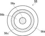
- FIG. 4 is a schematic cross-sectional view of the coaxial cable shown in FIG. 3.
- FIG. 5 is a schematic perspective view showing another example of the ultrasonic transducer unit of the ultrasonic observation unit at the distal end of the ultrasonic endoscope shown in FIGS.
- FIG. 5 is a cross-sectional view of another example of the ultrasonic transducer unit of the ultrasonic observation unit at the distal end of the ultrasonic endoscope shown in FIGS.
- FIG. 5 is a longitudinal sectional view of an example of another ultrasonic transducer unit of the ultrasonic observation unit at the distal end of the ultrasonic endoscope shown in FIGS.
- FIG. 10 is a cross-sectional view of another example of the ultrasonic transducer unit of the ultrasonic observation unit at the distal end portion of the ultrasonic endoscope shown in FIG. 9. It is the elements on larger scale of the front-end
- FIG. 13 is a partial vertical cross-sectional view of the distal end portion of the ultrasonic endoscope shown in FIG. 12, taken along line XIII-XIII shown in FIG.
- FIG. 14 is a partial longitudinal sectional view of another example of the ultrasonic transducer unit shown in FIG. 13.
- FIG. 15 is a partial longitudinal sectional view of another example of the ultrasonic transducer unit shown in FIGS. 13 and 14.
- FIG. 1 is a schematic configuration diagram showing an example of the configuration of an ultrasonic inspection system using the ultrasonic endoscope of the present invention.
- An ultrasonic examination system 10 shown in FIG. 1 is used for observing the gallbladder or pancreas, which is difficult to obtain by ultrasonic examination from the body surface of a subject such as a patient.
- an ultrasonic observation unit 36 that acquires an ultrasonic tomographic image (hereinafter referred to as an ultrasonic image) and an endoscope optical image (hereinafter referred to as an endoscopic image) are acquired.
- an ultrasonic image an ultrasonic tomographic image
- an endoscope optical image hereinafter referred to as an endoscopic image
- the ultrasonic endoscope 12 of the present invention having the endoscope observation unit 38 is inserted into the body cavity of the subject, and the ultrasonic image of the observation target portion of the subject is observed while observing the endoscopic image of the subject. Is something to get.
- an ultrasonic inspection system 10 includes an ultrasonic endoscope 12 having a heat dissipation structure that is a feature of the present invention, an ultrasonic processor device 14 that generates an ultrasonic image, and an endoscopic image.
- the ultrasonic inspection system 10 further includes a water supply tank 21a for storing cleaning water and the like, and a suction pump 21b for sucking inhaled matter (including supplied cleaning water) in the body cavity.
- the ultrasonic inspection system 10 further supplies a cleaning water in the water supply tank 21 a or a gas such as external air to a pipe line (not shown) in the ultrasonic endoscope 12.
- a pump or the like may be provided.
- the ultrasonic endoscope 12 shown in FIG. 1 has an ultrasonic observation unit 36 and an endoscope observation unit 38 having a heat dissipation structure, which is a feature of the present invention, at the tip, and images the body cavity of the subject. Then, an ultrasonic image (echo signal) and an endoscopic image (image signal) are acquired, respectively.
- the ultrasonic endoscope 12 includes an ultrasonic observation unit 36 and an endoscopic observation unit 38 at the distal end, and is connected to an insertion unit 22 to be inserted into a body cavity of a subject and a proximal end portion of the insertion unit 22.
- the operation unit 24 is used by an operator such as a doctor or an engineer, and the universal cord 26 is connected to the operation unit 24 at one end.
- the operation unit 24 includes an air / water supply button 28a for opening / closing an air / water supply pipe line (not shown) from the water supply tank 21a and a suction button 28b for opening / closing a suction pipe line (not shown) from the suction pump 21b.
- a pair of angle knobs 29 and 29 and a treatment instrument insertion port (forceps port) 30 are provided in parallel.
- the water supply tank 21a stores cleaning water and the like supplied to the air / water supply conduit in the ultrasonic endoscope 12 for cleaning the endoscope observation unit 38 and the like of the ultrasonic endoscope 12. Is for.
- the air / water supply button 28a ejects gas such as air supplied from the water supply tank 21a via the air / water supply conduit and water such as cleaning water from the endoscope observation section 38 on the distal end side of the insertion section 22. Used to make
- the suction pump 21b sucks a suction pipe (not shown) in order to suck a suction substance (including supplied cleaning water) from the distal end side of the ultrasonic endoscope 12. is there.
- the suction button 28b is used to suck a suction substance in the body cavity from the distal end side of the insertion portion 22 by the suction force of the suction pump 21b.
- the treatment instrument insertion port 30 is for inserting a treatment instrument such as a forceps, a puncture needle, or a high-frequency knife.
- the other end of the universal cord 26 is connected to the ultrasonic connector 32 a connected to the ultrasonic processor device 14, the endoscope connector 32 b connected to the endoscope processor device 16, and the light source device 18.
- a light source connector 32c to be connected is provided.
- the ultrasonic endoscope 12 is detachably connected to the ultrasonic processor device 14, the endoscope processor device 16, and the light source device 18 through the connectors 32a, 32b, and 32c, respectively.
- the light source connector 32c is connected to an air / water supply tube 34a for connecting the water supply tank 21a, a suction tube 34b for connecting the suction pump 21b, and the like.
- the insertion portion 22 is formed of a hard member in order from the distal end side, and is connected to a distal end portion (hard distal end portion) 40 having an ultrasonic observation portion 36 and an endoscope observation portion 38, and a proximal end side of the distal end portion 40.
- a plurality of bending pieces are connected to each other, and the bending portion 42 that can be bent, and the base end side of the bending portion 42 and the distal end side of the operation portion 24 are connected to each other.
- a soft part 43 having The bending portion 42 is remotely bent by turning a pair of angle knobs 29, 29 provided in the operation portion 24. Thereby, the front-end
- a balloon in which an ultrasonic transmission medium (for example, water, oil, etc.) covering the ultrasonic observation unit 36 is injected may be detachably attached to the distal end portion 40. Since the ultrasonic wave and the echo signal are significantly attenuated in the air, an ultrasonic transmission medium (ultrasonic wave) of the ultrasonic observation unit 36 is obtained by injecting an ultrasonic transmission medium into the balloon and expanding the balloon and bringing it into contact with the observation target part. It is possible to eliminate the air from between the ultrasonic transducer) array (50: see FIGS. 2 to 4) and the site to be observed, and to prevent attenuation of ultrasonic waves and echo signals.
- an ultrasonic transmission medium for example, water, oil, etc.
- the ultrasonic processor device 14 includes an ultrasonic transducer unit (46: FIGS. 2 to 4, 7, and 8 of the ultrasonic observation unit 36 at the distal end 40 of the insertion unit 22 of the ultrasonic endoscope 12.
- the ultrasonic transducer array (50) (see FIGS. 2 to 4, 7 and 8) generates and supplies ultrasonic signals (data) for generating ultrasonic waves.
- the ultrasonic processor device 14 receives and acquires an echo signal (data) reflected from the observation target site from which the ultrasonic wave is radiated by the ultrasonic transducer array (50).
- various signal (data) processes are performed to generate an ultrasonic image displayed on the monitor 20.
- the endoscope processor device 16 is an image obtained from an observation target portion illuminated by illumination light from the light source device 18 in the endoscope observation unit 38 at the distal end portion 40 of the insertion unit 22 of the ultrasonic endoscope 12. Receives and acquires image signals (data), and performs various signal (data) processing and image processing on the acquired image signals to generate an endoscopic image to be displayed on the monitor 20 It is.
- the processor devices 14 and 16 may be constituted by a processor such as a PC (personal computer).
- the light source device 18 picks up red light (R), green light (G), and blue light in order to obtain an image signal by imaging an observation target part in the body cavity by the endoscope observation unit 38 of the ultrasonic endoscope 12.
- Illumination light such as white light or specific wavelength light such as light (B) is generated and supplied to the ultrasonic endoscope 12, and a light guide (not shown) in the ultrasonic endoscope 12 is shown. Or the like, and is emitted from the endoscope observation section 38 at the distal end portion 40 of the insertion section 22 of the ultrasonic endoscope 12 to illuminate the observation target site in the body cavity.
- the monitor 20 receives each video signal generated by the ultrasonic processor device 14 and the endoscope processor device 16 and displays an ultrasonic image or an endoscopic image. These ultrasonic images and endoscopic images can be displayed on the monitor 20 by appropriately switching only one of the images or displaying both images at the same time.
- a monitor for displaying an ultrasonic image and a monitor for representing an endoscopic image may be provided separately, and in any other form, these ultrasonic image and endoscopic image are displayed. You may make it do.
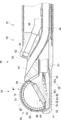
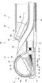
- FIG. 2 is a partially enlarged plan view showing the distal end portion of the ultrasonic endoscope shown in FIG. 1 and the vicinity thereof.
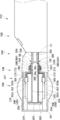
- 3 is a cross-sectional view taken along the line III-III shown in FIG. 2, and is a longitudinal sectional view obtained by cutting the distal end portion of the ultrasonic endoscope shown in FIG. 2 along a center line along its longitudinal direction.
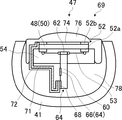
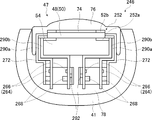
- 4 is a sectional view taken along the line IV-IV shown in FIG.
- FIG. 4 which is cut along the center line of the arc structure of the ultrasonic transducer array of the ultrasonic observation section at the distal end of the ultrasonic endoscope shown in FIG. It is a cross-sectional view.
- FIG. 4 the drawing is simplified for the sake of explanation, and the coaxial cable (56: see FIG. 3) is omitted.
- the distal end portion 40 of the ultrasonic endoscope 12 has an ultrasonic observation unit 36 for acquiring an ultrasonic image on the distal end side, and an endoscopic image on the proximal end side.
- an endoscope observation part 38 and a treatment instrument outlet 44 between them both of which are a hard resin or the like that becomes a distal end body of the distal end part 40 of the ultrasonic endoscope 12 Attached to and held by an exterior member 41 made of a hard member.
- an exterior member 41 made of a hard member.
- the treatment instrument outlet 44 is provided between the ultrasonic observation unit 36 and the endoscope observation unit 38, but the present invention is not particularly limited to the illustrated example, and the endoscope It may be provided in the observation unit 38 or may be provided on the base end side (curving unit 42 side) from the endoscope observation unit 38.
- the ultrasonic observation unit 36 includes an ultrasonic transducer unit 46 and an exterior member 41 that attaches and holds the ultrasonic transducer unit 46.
- the ultrasonic transducer unit 46 includes an ultrasonic transducer array 50 including a plurality of ultrasonic transducers (transducers) 48, an electrode portion 52 provided on the end side in the width direction of the ultrasonic transducer array 50, A backing material layer 54 that supports each ultrasonic transducer 48 of the acoustic transducer array 50 from the lower surface side, and a wiring substrate 60 that is embedded in the backing material layer 54 and electrically connected to the electrode portion 52;
- the insulating layer 70 disposed along the side surface in the width direction of the backing material layer 54, and the side surface side in the width direction of the backing material layer 54, on the side opposite to the backing material layer 54 with respect to the insulating layer 70 And a filler layer 78 that fills the space between the exterior member 41 and the backing material layer 54.
- the wiring substrate 60 is disposed with one end side buried in the backing material layer 54, a portion buried in the backing material layer 54 of the wiring substrate 60, and a plurality of ultrasonic transducers 48 and the electrode part 52 electrically connected are electrically connected.
- a portion of the wiring board 60 opposite to the plurality of ultrasonic transducers 48 (below the backing material layer 54) with respect to the backing material layer 54 has a plurality of coaxial cables 56. Electrically connected.
- the plurality of coaxial cables 56 whose one ends are electrically connected to the wiring board 60 are formed using the outer skin 57 on the proximal end side (universal cord 26 side) of the distal end portion 40 of the insertion portion 22.
- the coaxial cables 56 are drawn out and electrically connected to the wiring board 60 when wiring.
- the plurality of coaxial cables 56 includes signal lines 56a that are electrically connected to a plurality of connection portions 66 of a wiring portion 64 of a wiring board 60 described later on the center side, and are arranged outside the signal lines 56a.
- the grounding in the present invention is not limited to zeroing the potential of the conductive member, but for example, connecting the conductive member to a member having a large electric capacity to maintain the conductive member at a constant low voltage. This includes cases where
- the coaxial cable 56 is used.
- a signal line for transmitting and receiving a voltage signal by being electrically connected to the plurality of ultrasonic transducers 48 and a plurality of ultrasonic transducers 48 described later.
- the cable has a shield member that can be grounded and is electrically connected to the vibrator ground 52b (shield cable)
- a cable having a configuration different from that of the coaxial cable 56 may be used.
- the shielded cable includes a plurality of signal wires covered with an insulating outer sheath and a plurality of conductors that can be grounded on the center side, and includes a sheath covering the plurality of signal wires and the conductive wires.
- a cable having a known structure such as a cable unit can be used.
- the arrangement of the signal lines and the conductors of the cable unit is not limited to the above, and the plurality of signal lines and the conductors may be randomly arranged in the outer skin that covers them.
- the ultrasonic transducer unit 46 further includes an acoustic matching layer 74 stacked on the ultrasonic transducer array 50 and an acoustic lens 76 stacked on the acoustic matching layer 74. That is, the ultrasonic transducer unit 46 includes a laminate 47 of the acoustic lens 76, the acoustic matching layer 74, the ultrasonic transducer array 50, and the backing material layer 54.
- the acoustic matching layer 74 is for achieving acoustic impedance matching between a subject such as a human body and the ultrasonic transducer 48.
- the acoustic lens 76 attached on the acoustic matching layer 74 is for converging the ultrasonic waves emitted from the ultrasonic transducer array 50 toward the observation target site.
- the acoustic lens 76 is made of, for example, silicon resin (millable silicon rubber (HTV rubber), liquid silicon rubber (RTV rubber), etc.), butadiene resin, polyurethane resin, or the like.
- the acoustic lens 76 is made of titanium oxide, alumina, silica, or the like as necessary. The powder is mixed.
- the ultrasonic transducer array 50 of the ultrasonic transducer unit 46 includes a plurality of, for example, 48 to 192 rectangular parallelepiped ultrasonic transducers (transducers) 48 to 192 arranged in a convex arc shape toward the outside. It is an array of channels (CH). That is, the ultrasonic transducer array 50 is formed by arranging a plurality of ultrasonic transducers 48 as an example at a predetermined pitch in a one-dimensional array as shown in the drawing.
- CH channels
- the ultrasonic transducers 48 constituting the ultrasonic transducer array 50 are arranged at regular intervals in a convex curve along the axial direction of the distal end portion 40 (longitudinal axis direction of the insertion portion 22). These are sequentially driven based on a drive signal inputted from the ultrasonic processor unit 14. Thereby, convex electronic scanning is performed with the range in which the ultrasonic transducers 48 shown in FIG. 2 are arranged as the scanning range.
- the ultrasonic transducer array 50 has a width direction of the ultrasonic transducer array 50 perpendicular to the AZ direction, that is, an ultrasonic transducer, rather than a direction (AZ (azimuth) direction) parallel to the bottom surface of the backing material layer 54.
- the length of 48 in the longitudinal direction (EL (elevation) direction) is shorter, and the rear end side is inclined and disposed.
- the ultrasonic transducer 48 has a configuration in which electrodes are formed on both surfaces of a piezoelectric thick film such as PZT (lead zirconate titanate) or PVDF (polyvinylidene fluoride).
- One electrode is an individual electrode 52 a that is individually independent for each ultrasonic transducer 48, and the other electrode is a transducer ground (vibrator ground electrode) 52 b that is a common electrode common to all the ultrasonic transducers 48. It has become.
- the plurality of individual electrodes 52 a are disposed on the lower surface of the end portion of the plurality of ultrasonic transducers 48, and the transducer ground 52 b is provided on the upper surface of the end portion of the ultrasonic transducer 48. Yes.
- the plurality of individual electrodes 52 a and the vibrator ground 52 b constitute an electrode unit 52.
- a gap between two adjacent ultrasonic transducers 48 is filled with a filler such as an epoxy resin.
- the ultrasonic transducer unit 46 of the ultrasonic observation unit 36 when each ultrasonic transducer 48 of the ultrasonic transducer array 50 is driven and voltage is applied to both electrodes of the ultrasonic transducer 48, the piezoelectric body is The ultrasonic waves are sequentially generated by vibration, and the ultrasonic waves are irradiated toward the observation target portion of the subject. Then, by sequentially driving a plurality of ultrasonic transducers 48 with an electronic switch such as a multiplexer, the scanning range along the curved surface on which the ultrasonic transducer array 50 is arranged, for example, about several tens mm from the curvature center of the curved surface. In range, ultrasound is scanned.
- the piezoelectric body vibrates to generate a voltage, and an electrical signal (ultrasonic detection signal) corresponding to the received ultrasound echo.
- the ultrasonic image is displayed on the monitor 20 as an ultrasonic image.
- the drive voltage is applied to the plurality of ultrasonic transducers 48, and the piezoelectric bodies constituting the plurality of ultrasonic transducers 48 vibrate to generate ultrasonic waves to be transmitted toward the object.
- the ultrasonic waves transmitted from the plurality of ultrasonic transducers 48 are reflected by the object, and the ultrasonic transducers 48 receive the ultrasonic echoes to vibrate the piezoelectric body.
- the voltage signal is generated, heat is generated in each piezoelectric body constituting the plurality of ultrasonic transducers 48.
- drive signals voltage signals
- the heat generated in the piezoelectric body increases.
- the heat dissipation structure which is a feature of the present invention, at the distal end portion 40 of the ultrasonic endoscope 12, the heat generated in the piezoelectric body can be efficiently dissipated and the accuracy of ultrasonic diagnosis is improved. be able to.
- the electrode unit 52 of the ultrasonic transducer unit 46 is ultrasonic vibration that is perpendicular to the arcuate surface due to the arrangement of a plurality (48 to 192) of ultrasonic transducers 48.
- a plurality of (48 to 192) individual electrodes 52a are provided in an arc shape on the end face side (of each ultrasonic transducer 48) of the child array 50, and are respectively conducted to the plurality (48 to 192) of ultrasonic transducers 48.
- the electrode unit 52 includes transducer grounds 52b of the plurality of ultrasonic transducers 48.
- vertical is not limited to 90 degrees, but includes substantially vertical, for example, 90 degrees ⁇ 5 degrees, that is, an angle in the range of 85 degrees to 95 degrees.
- the electrode unit 52 is provided on the end face side of the ultrasonic transducer array 50 that is perpendicular to the arrangement plane of the ultrasonic transducers 48.
- the number of the ultrasonic transducers 48 is small, It may be on the end face side. Since it is preferable that the number of the ultrasonic transducers 48 is large, it is preferable that the plurality of individual electrodes 52 a be provided on both outer side surfaces of the ultrasonic transducer array 50. A plurality of individual electrodes 52a may be provided not on the end face side of the ultrasonic transducer array 50 but on the center side.
- the ultrasonic transducers 48 are provided in multiple rows, for example, by providing two rows of ultrasonic transducers 48 in the width direction, a plurality of individual electrodes 52 a are provided on the center side of the ultrasonic transducer array 50. Even if the number of channels is large, wiring can be performed efficiently. In this manner, by adding the plurality of individual electrodes 52a to the outer side surfaces of the ultrasonic transducer array 50 and providing them on the center side, the number of ultrasonic transducers 48, that is, the number of channels can be increased. In the example shown in FIG.
- the plurality of individual electrodes 52 a are configured by the individual electrodes 52 a provided on the end face side in the longitudinal direction of each ultrasonic transducer 48, but the present invention is not limited to this, Even if the ultrasonic transducer array 50 is provided on any one of the outer side surface, both outer side surfaces, and the center side, the individual electrode 52a can be used as long as it is electrically connected to the individual electrode 52a of the ultrasonic transducer 48. Alternatively, another electrode connected by wiring may be used.
- the electrode portion 52 includes the vibrator ground 52b directly, but may include an electrode connected to the vibrator ground 52b by wiring.
- the plurality of individual electrodes 52a and the vibrator ground 52b of the electrode part 52 are preferably provided as electrode pads.
- the backing material layer 54 of the ultrasonic transducer unit 46 is inside with respect to the arrangement surface of the plurality of ultrasonic transducers 48, that is, the ultrasonic transducer array 50. It is the layer of the member which consists of a backing material arrange
- the backing material is made of a material having rigidity such as hard rubber, and an ultrasonic attenuating material (ferrite, ceramics, etc.) is added as necessary. Therefore, the ultrasonic transducer array 50 includes a plurality of rectangular transducers 48 in the illustrated example on the upper surface of the arc-shaped upper surface of the backing material layer 54 formed in a convex arc shape in cross section.
- the ultrasonic transducers 48 are arranged at equal intervals so that the longitudinal directions are parallel, that is, a plurality of ultrasonic transducers 48 are arranged in an arc shape and outward.
- the shape of the backing material layer 54 may be any shape that does not impair the above role, and may have a substantially semi-cylindrical shape as shown in FIG. 3 and FIG. A recess may be provided so that it can be stored.
- the filler layer 78 of the ultrasonic transducer unit 46 fills the space between the exterior member 41 and the backing material layer 54, and includes the wiring substrate 60, the signal line 56 a of the coaxial cable 56, the copper foil 72, and various wirings. Also has a role to fix the part. Further, the filler layer 78 has an acoustic impedance with the backing material layer 54 so as not to reflect the ultrasonic signal propagated from the ultrasonic transducer array 50 to the backing material layer 54 side at the boundary surface with the backing material layer 54. Are preferably matched with a certain accuracy. Furthermore, in order to increase the efficiency of dissipating heat generated in the plurality of ultrasonic transducers 48, the filler layer 78 preferably has heat dissipation. When the filler layer 78 has heat dissipation, heat is received from the backing material layer 54, the wiring board 60, the copper foil 72, and the shield layer 56c of the coaxial cable 56, so that the heat dissipation efficiency can be improved.
- the wiring board 60 of the ultrasonic transducer unit 46 is disposed on the laminated body 47 side composed of the ultrasonic transducer array 50, the backing material layer 54 and the like with respect to the copper foil 72 which is a heat conducting member.
- the wiring substrate 60 is disposed so that the ultrasonic transducer array 50 side is embedded in the backing material layer 54, and a plurality of electrode portions 52 are provided in the backing material layer 54.
- the individual electrodes 52a are wired.
- the wiring board 60 is provided at a lower portion of the backing material layer 54 of the wiring board 60 and a plurality of electrode pads 62 for electrical connection with the plurality of individual electrodes 52 a of the electrode part 52, and a plurality of coaxial cables 56.
- a plurality of coaxial cables provided at a lower end portion of the backing material layer 54 of the wiring board 60 and a wiring portion 64 composed of a plurality of connection portions 66 which are terminals electrically connected to the signal line 56a of the wiring board 60.
- 56 ground layers 68 electrically connected to 56 shield layers 56c (see FIGS. 4 and 5).
- the plurality of electrode pads 62 and the plurality of connection portions 66 of the wiring portion 64 are electrically connected to each other via wiring (not shown) provided on the wiring substrate 60.
- the vibrator ground 52b and the ground bar 68 may be electrically connected by using a conducting wire passing through the side surface of the multilayer body 47 or the like.
- a conducting wire passing through the side surface of the multilayer body 47 or the like may be appropriately used as a method for conducting the vibrator ground 52b and the ground bar 68.
- the electrical connection means between the plurality of electrode pads 62 and the plurality of individual electrodes 52a of the wiring board 60 may be a well-known connection means such as filling and solidifying the backing material after soldering the signal lines. .
- the wiring portions of the plurality of individual electrodes 52a and the plurality of electrode pads 62 are protected by the backing material layer 54. The possibility of disconnection in the portion to be reduced is reduced. Further, the wiring board 60 does not need to be embedded in the backing material layer 54 as long as it electrically connects the electrode portion 52 and the signal line 56a.
- the electrode portion 52 when the electrode portion 52 is provided to extend to the end surface in the width direction of the ultrasonic transducer array 50, the side surfaces in the width direction of the ultrasonic transducer array 50 and the backing material layer 54 (of the laminate 47). Side surface), that is, between the ultrasonic transducer array 50 and the backing material layer 54 and the copper foil 72.
- the electrode part 52 and the wiring board 60 can be wired after the backing material layer 54 is solidified, workability during wiring is improved. If the number of the plurality of ultrasonic transducers 48 (the number of channels of the ultrasonic transducer array 50) is large and it is difficult to secure a wiring space with the plurality of coaxial cables 56 on the wiring substrate 60, the wiring is performed. The number of the substrates 60 may be increased as appropriate.
- the insulating layer 70 of the ultrasonic transducer unit 46 is affixed along the side surfaces in the width direction of the ultrasonic transducer array 50 and the backing material layer 54, and the ultrasonic transducer array 50 is attached to the backing material layer 54. Is formed so as to extend beyond the backing material layer 54 (under the backing material layer 54).
- the insulating layer 70 is not formed between the copper foil 72 and the ultrasonic transducer array 50 and the backing material layer 54, particularly between the copper foil 72 and the connection portion 66 of the wiring substrate 60, the copper foil 72 and the connection portion are formed. 66 interferes, and the ultrasonic echo signal (voltage signal) observed causes noise received by the copper foil 72 from the outside.
- the insulating layer 70 is preferably formed so as to cover the connection portion 66 so that the copper foil 72 does not contact the connection portion 66 of the wiring portion 64 of the wiring substrate 60. Therefore, as in the example illustrated in FIGS. 3 and 4, the insulating layer 70 may be removed at a portion where the ground bar 68 and the copper foil 72 of the wiring portion 64 are connected.
- the insulating layer 70 since the insulating layer 70 is formed between the copper foil 72 and the ultrasonic transducer array 50 and the backing material layer 54, the insulating layer 70 has a certain thickness or is a silicon having thermal conductivity. An insulating material having thermal conductivity such as a sheet is preferable.
- the copper foil 72 of the ultrasonic transducer unit 46 is attached to the side surface in the width direction of the ultrasonic transducer array 50 and the backing material layer 54 and pasted to the insulating layer 70 on the opposite side of the backing material layer 54. Arranged. Further, the copper foil 72 is disposed on the opposite side of the ultrasonic transducer array 50 with respect to the backing material layer 54 so as to extend beyond the backing material layer 54, and is disposed on the ground bar 68 of the wiring portion 64. Connected. The copper foil 72 causes heat generated from the plurality of ultrasonic transducers 48 constituting the ultrasonic transducer array 50 to pass through the side surfaces in the width direction of the ultrasonic transducer array 50 and the backing material layer 54 and the insulating layer 70.
- the connecting means between the copper foil 72 and the ground bar 68 may be any means that can be electrically and thermally connected to the plurality of ultrasonic vibrators 48 so as not to be damaged by heat.
- a connection means that can be used at a temperature lower than the temperature is preferable.
- a known method such as solder or silver paste which does not require a certain amount of heat can be used.
- the copper foil 72 may be connected to the ground bar 68 of the wiring portion 64 as in the example shown in FIGS. 3 and 4, but the ultrasonic vibration is different as in another example of the present embodiment shown in FIG.
- the ultrasonic transducer array 50 and the backing material layer 54 of the child unit 69 may be folded back to the side surface in the width direction and connected to the ground bar 68. That is, the copper foil 72 together with the insulating layer 70 is connected to the ground bar 68 so that the surface of the copper foil 72 facing away from the ultrasonic transducer array 50 and the backing material layer 54 is connected to the ground bar 68. It is folded and arranged.
- the copper foil 72 can be disposed on both side surfaces in the width direction of the ultrasonic transducer array 50 and the backing material layer 54 (both side surfaces of the multilayer body 47). As shown in FIG. 4, when only one wiring substrate 60 is provided, only the copper foil 72 is ultrasonically vibrated on the opposite side of the surface of the wiring substrate 60 where the wiring part 64 is provided. You may affix on the side surface of the width direction of the child array 50 and the backing material layer 54. FIG. Further, for example, when the electrode portions 52 that are electrically connected to the plurality of ultrasonic transducers 48 are disposed on both side surfaces in the width direction of the ultrasonic transducer array 50, or two or more wiring boards 60 are disposed.
- the insulating layer 70 and the copper foil 72 may be provided on both side surfaces in the width direction of the ultrasonic transducer array 50 and the backing material layer 54, respectively.
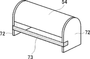
- Each copper foil 72 is preferably connected by a heat conductive member such as copper foil 73.
- the copper foil 73 which is a heat conductive member, passes through the side surface side in the width direction of the wiring substrate 60, and the copper foils 72 disposed on both side surfaces of the laminate 47 are soldered or silvered. It is thermally connected using paste or the like.
- the difference is in the number of the individual electrodes 52a (the number of channels of the ultrasonic transducer array 50) of the electrode part 52 that is electrically connected to the wiring boards 60, 60 to which the pair of copper foils 72, 72 are thermally connected. If there is, the heat conducted to both the copper foils 72, 72 is evenly distributed via the ground bar 68 of each wiring board 60, and the shield layers 56c of the plurality of coaxial cables 56 (FIGS. 3 and 5)). In addition, when only one wiring board 60 is provided, the heat from the plurality of ultrasonic transducers 48 is larger than when the copper foil 72 is provided only on one side surface of the laminate 47. Therefore, the heat dissipation efficiency is improved.
- the heat conductive member which thermally connects the copper foils 72 disposed on both side surfaces of the laminated body only needs to have a high thermal conductivity.
- a known heat conducting member such as a silicon sheet can be used.
- the shape of the heat conducting member is not limited to the foil shown in FIG. 6, and may be a plate shape or a linear shape.
- FIG. 6 is a schematic diagram for explaining that the copper foils 72 disposed on both side surfaces of the laminated body are thermally connected to each other by using a heat conductive member. Only the layer 54 is described, and further, wiring of each part such as the wiring board 60, the insulating layer 70, the coaxial cable 56, and the like is omitted.
- the wiring part 64 of the wiring board 60 is composed of a plurality of connection parts 66 that are terminals electrically connected to the signal lines 56 a of the plurality of coaxial cables 56.
- the wiring board 60 is provided in the lower portion of the backing material layer 54.
- the plurality of connection portions 66 of the wiring portion 64 are electrically connected to the plurality of electrode pads 62 of the wiring substrate 60 through wirings provided on the wiring substrate 60, respectively. Therefore, the wiring part 64 has at least a plurality of connection parts 66 equal to or greater than the number of the plurality of ultrasonic transducers 48 (the number of channels of the ultrasonic transducer array 50) electrically connected to the electrode pads 62. It is preferable.
- the wiring unit 64 may be composed of a plurality of connection units 66 arranged in multiple rows.
- the wiring portion 64 has a copper foil 72 side surface disposed so as not to interfere with the copper foil 72 disposed on the side surface in the width direction of the multilayer body 47. Insulating layers 70 and 71 formed on 72.
- the signal line 56a of the coaxial cable 56 is electrically connected to the connecting portion 66 and the shield layer 56c of the coaxial cable 56 is electrically connected to the ground bar 68, as in the example shown in FIGS.
- the wiring part 64 is preferably provided on the same surface of the wiring board 60 as the ground bar 68. Of course, the wiring part 64 may be provided at any place on the wiring board 60 as long as the workability during wiring is not impaired.
- the ground bar 68 of the wiring board 60 is electrically connected to the shield layer 56 c of the plurality of coaxial cables 56, and the copper foil 72 disposed along the side surface of the multilayer body 47.
- a conductive member that is thermally connected Therefore, heat generated in the plurality of ultrasonic transducers 48 can be radiated to the shield layers 56 c of the plurality of coaxial cables 56 via the copper foil 72 and the ground bar 68.
- a low-temperature solder is used to prevent damage due to heat at a portion where the other members of the ground bar 68 and the copper foil 72 are thermally connected.
- a thermal connection means that can be used at a low temperature such as silver paste.
- a thermal connection means that can be used at a lower temperature than the connection portion between the ground bar 68 to which the copper foil 72 is thermally connected and the shield layer 56c of the plurality of coaxial cables 56.
- ground bar 68 is a conductive member, when the shield layers 56c of the plurality of coaxial cables 56 are grounded, each of the plurality of shield layers 56c electrically connected to the ground bar 68 is provided.
- the ground potential of the copper foil 72 connected to the ground bar 68 can be grounded.
- the copper foil 72 since the copper foil 72 has a low potential, even when the copper foil 72 receives noise (voltage signal) such as an electromagnetic wave from the outside, the copper foil 72 is electromagnetic with the plurality of ultrasonic transducers 48. Since no interference occurs, the noise from the copper foil 72 can be prevented from being included in the ultrasonic echo signals (voltage signals) of the plural ultrasonic transducers 48.
- the heat generated in the plurality of ultrasonic transducers 48 and conducted to the copper foil 72 is shielded from the plurality of coaxial cables 56 via the ground bar 68.
- the heat was dissipated to 56c.
- the heat dissipating structure of the present invention only needs to be able to dissipate heat generated in the plurality of ultrasonic transducers 48 to the shield layers 56 c of the plurality of coaxial cables 56, and does not necessarily have to dissipate heat via the ground bar 68.
- FIG. 8 instead of the wiring board 61 of the ultrasonic transducer unit 75 not having the ground bar 68 shown in FIGS.
- the shield layer 56c of the plurality of coaxial cables 56 has a collective ground portion 58 that is electrically connected.
- the collective ground portion 58 includes the copper foils 77 (disposed along the side surfaces in the width direction of the shield layers 56 c of the plurality of coaxial cables 56 and the ultrasonic transducer array 50 and the backing material layer 54.
- the first heat conductive member is an electrically connected conductive member, and is disposed closer to the proximal end side of the ultrasonic endoscope 13 than the wiring substrate 61 in the plurality of coaxial cables 56.
- the collective ground portion 58 is disposed between the wiring board 61 and the outer skin 57 of the plurality of coaxial cables 56.
- the outer sheath 56d is removed from the plurality of coaxial cables 56 at a portion electrically connected to the collective ground portion 58.
- the coaxial cable 56 has at least a signal line 56a and an inner skin 56b between the wiring board 61 and the collective ground portion 58.
- the copper foil 77 extends from the ultrasonic transducer array 50 and the backing material layer 54 over the wiring substrate 61 to the collective ground portion 58 and is thermally connected to the collective ground portion 58. Therefore, the heat generated in the plurality of ultrasonic transducers 48 is radiated to the shield layers 56 c of the plurality of coaxial cables 56 via the copper foil 77 and the collective ground portion 58. Even when a plurality of wiring boards 61 are provided, the method described above can be used. In that case, the heat generated in the plurality of ultrasonic transducers 48 can be radiated to the shield layers 56c of all the coaxial cables 56 connected to the plurality of wiring boards 61 without any shortage.
- the thermal connection means between the collective ground portion 58 and the copper foil 77 low melting point solder or silver paste is used similarly to the ground bar 68 of the wiring board 60 shown in FIGS. It is preferable to use a low temperature such as the one.
- a low temperature such as the one.
- the collective ground portion 58 and the shield layers 56c of the plurality of coaxial cables 56 are thermally connected using solder, the collective ground portion 58 and the shield layers 56c of the plurality of coaxial cables 56 are connected.
- the collective ground portion 58 and the copper foil 77 may be connected using a solder having a melting point lower than that of the used solder.
- the shield layers 56c of the plurality of coaxial cables 56 are grounded in the same manner as the ground bar 68 of the wiring board 60 shown in FIGS.
- the ground potentials of the plurality of shield layers 56c can be set to the same potential.
- the ultrasonic echo signals (voltage signals) of the plurality of ultrasonic transducers 48 include noise from the outside. Can not be.
- heat generated from the plurality of ultrasonic transducers 48 constituting the ultrasonic transducer array 50 is thermally conducted.
- the heat can be transmitted to the copper foil 72 or 77 which is a member, and further, can be radiated to the shield layers 56 c of the plurality of coaxial cables 56 via the ground bar 68 or the collective ground portion 58.
- the connection part 66 of the wiring part 64 connected to the signal lines 56a of the plurality of coaxial cables 56 is covered with the insulating layer 70 or 71, the connection part 66 and the copper foil 72 or 77 do not interfere with each other.
- the noise received from the outside can be prevented from being included in the ultrasonic echo signal (voltage signal). Furthermore, all of the heat dissipation structures described above are simple structures and do not occupy a large space in the distal end portions 40 of the ultrasonic endoscopes 12 and 13. Therefore, heat can be efficiently radiated while the size of the distal end portion 40 of the insertion portion 22 is kept small.
- the heat dissipation structure of the convex ultrasonic endoscopes 12 and 13 has been described.
- the above heat dissipation structure does not depend on the shape of the ultrasonic endoscope, and other types such as a radial type are available.
- the present invention can also be applied to an ultrasonic endoscope having the following shape.
- the endoscope observation unit 38 includes an observation window 80, an objective lens 82, a solid-state imaging device 84, an illumination window 86, a cleaning nozzle 88, a wiring cable 89 including a coaxial cable, and the like. Composed.
- the observation window 80 is attached so as to face obliquely above the distal end portion 40.
- the reflected light of the observation target site incident from the observation window 80 is imaged on the imaging surface of the solid-state imaging device 84 by the objective lens 82.
- the solid-state imaging device 84 photoelectrically converts the reflected light of the site to be observed that has passed through the observation window 80 and the objective lens 82 and is imaged on the imaging surface, and outputs an imaging signal.
- Examples of the solid-state imaging device 84 include a CCD (Charge Coupled Device) and a CMOS (Complementary Metal Oxide Semiconductor).
- the captured image signal output from the solid-state imaging device 84 is transmitted to the endoscope processor device 16 by the universal code 26 via the wiring cable 89 extending from the insertion unit 22 to the operation unit 24.
- the endoscope processor device 16 performs various signal processing and image processing on the transmitted imaging signal, and displays the signal on the monitor 20 as an endoscope optical image.
- the illumination windows 86 are provided on both sides of the observation window 80.
- An emission end of a light guide (not shown) is connected to the illumination window 86.
- the light guide extends from the insertion portion 22 to the operation portion 24, and an incident end thereof is connected to the light source device 18 connected via the universal cord 26.
- Illumination light emitted from the light source device 18 travels through the light guide and is irradiated from the illumination window 86 onto the site to be observed.
- the cleaning nozzle 88 also cleans the surface of the observation window 80 and the illumination window 86 from the water supply tank 21a through the air / water supply pipe line in the ultrasonic endoscope 12 to the observation window. 80 and spray toward the illumination window 86.
- the distal end portion 40 is provided with a treatment instrument outlet 44.
- the treatment instrument outlet 44 is connected to a treatment instrument channel 45 inserted into the insertion portion 22, and the treatment instrument inserted into the treatment instrument insertion slot 30 is connected to the treatment instrument outlet 45 via the treatment instrument channel 45. 44 is introduced into the body cavity.
- the treatment instrument outlet 44 is located between the ultrasonic observation unit 36 and the endoscope observation unit 38, the movement of the treatment instrument introduced into the body cavity from the treatment instrument outlet 44 is detected by ultrasonic waves. In the case of a configuration for confirming with an image, it is preferable to dispose it close to the ultrasonic observation unit 36.
- an upright for changing the direction in which the treatment tool introduced from the treatment tool outlet 44 into the body cavity may be provided inside the treatment tool outlet 44.
- a wire (not shown) is attached to the stand, and the standing angle of the stand is changed by a push-pull operation by the operation of the stand lever (not shown) of the operation unit 24, whereby the treatment tool can be set in a desired manner. Will be derived in the direction.
- the insertion unit 22 When observing the inside of a body cavity with the ultrasonic endoscope 12, first, the insertion unit 22 is inserted into the body cavity, and an endoscope optical image acquired by the endoscope observation unit 38 is observed on the monitor 20. Search for the site to be observed. Next, when the distal end portion 40 reaches the observation target region and an instruction to acquire an ultrasonic tomographic image is given, the signal line of the coaxial cable 56 provided in the ultrasonic endoscope 12 from the ultrasonic processor device 14. A drive control signal is input to the ultrasonic transducer 48 via 56 a, the wiring substrate 60, and the electrode unit 52. When the drive control signal is input, a prescribed voltage is applied to both electrodes of the ultrasonic transducer 48.
- the piezoelectric body of the ultrasonic vibrator 48 is excited, and ultrasonic waves are emitted to the observation target portion via the acoustic lens 76.
- an echo signal from the observation target part is received by the ultrasonic transducer 48.
- the irradiation of the ultrasonic wave and the reception of the echo signal are repeatedly performed while the driving ultrasonic transducer 48 is shifted by an electronic switch such as a multiplexer. Thereby, an ultrasonic wave is scanned to an observation object site
- an ultrasonic tomographic image is generated based on the detection signal received from the ultrasonic transducer 48 by receiving the echo signal.
- the generated ultrasonic tomographic image is displayed on the monitor 20.
- the specific heat dissipation structure has been described mainly in the case where there is one wiring board 60.
- the number of wiring boards 60 is not necessarily one, and the number of channels (the number of ultrasonic vibrators 48) of the ultrasonic transducer array 50 is large or the wiring space in the wiring board 60 is insufficient. Can appropriately increase the number of wiring boards 60 to be provided.
- a case where a plurality of wiring boards are disposed in the ultrasonic transducer unit will be described.
- the ultrasonic transducer unit 246 includes an electrode portion 252 provided on the outer surface of the ultrasonic transducer array 50 and a backing material layer 54 electrically connected to the electrode portion 252 on one end side.
- FPCs inner FPCs
- 290b, 290b, and copper foils 272, 272 disposed along both side surfaces (side surfaces of the laminated body 47) in the width direction of the ultrasonic transducer array 50 and the backing material layer 54.
- the number of FPCs 290a and 290b disposed in the ultrasonic transducer unit 246 shown in FIG. 9 is not limited to the number in the illustrated example, and may be appropriately determined according to the number of the plurality of ultrasonic transducers 48. You can increase or decrease. Further, FIG. 9 is simplified for the sake of explanation, and an insulating layer (not shown) and a plurality of coaxial cables (not shown) are omitted. Of course, in the ultrasonic transducer unit 246 of the present embodiment shown in FIG. 9, the surface (inner side) of the copper foil 272 on the backing material layer 54 side as in the first embodiment shown in FIGS. An insulating layer may be formed on the side surface so that the copper foil 272 and the wiring portion 264 of the FPC 290a described later do not interfere with each other.
- the electrode portion 252 of the ultrasonic transducer unit 246 is in the longitudinal direction of the arc-shaped surface of the plurality of ultrasonic transducers 48, that is, the shape of the rod-shaped body of the ultrasonic transducer 48.
- the electrode portion 252 of the ultrasonic transducer unit 246 is in the longitudinal direction of the arc-shaped surface of the plurality of ultrasonic transducers 48, that is, the shape of the rod-shaped body of the ultrasonic transducer 48.
- It consists of a plurality of individual electrodes 252a respectively connected to the ultrasonic transducer 48.
- the plurality of individual electrodes 252a are provided on both end surfaces of the ultrasonic transducer array 50.
- the individual electrodes 252a are provided only on one side. Also good.
- the place where the electrode portion 252 is disposed is not limited to the side surface side in the width direction of the ultrasonic transducer array 50 as in the first embodiment, and the ultrasonic transducer array 50 is not limited. It may be the center side in the width direction.
- the FPC 290a outside the ultrasonic transducer unit 246 is electrically connected at one end to the individual electrode 52a of the electrode portion 52 disposed on the end surface side in the width direction of the ultrasonic transducer array 50, and the side surface of the laminated body 47.
- the lower FPC 290 b extends below the backing material layer 54.
- the outer FPC 290 a extends below the backing material layer 54 and a plurality of electrode pads (not shown) for electrical connection with the plurality of individual electrodes 52 a of the electrode portion 52.
- a plurality of coaxial cables connected to signal lines (not shown) provided on a surface (outer surface) opposite to the center side of the ultrasonic transducer unit 246 of the FPC 290a.
- the wiring portion 264 including the connecting portion 266 and the FPC 290a are provided on the same surface as the wiring portion 264, and are electrically connected to the shield layer (not shown) of the plurality of coaxial cables and thermally connected to the copper foil 272.
- a ground bar 268 Therefore, the heat generated in the plurality of ultrasonic transducers 48 is radiated to the shield layers of the plurality of coaxial cables via the copper foil 272 and the ground bar 268 of the FPC 290a.
- the FPCs 290a and 290b are used as substrates that are electrically connected to the electrode part 52, but can be electrically connected to the electrode part 52 and extend below the backing material layer 54. If it is, it will not specifically limit to FPC290a and 290b.
- a wiring board made of a hard member may be used, and a part of the wiring board may be embedded in the backing material layer 54 as in the wiring board 60 of the first embodiment shown in FIGS. It may be disposed only on the lower side of the material layer 54.
- the FPC 290b on the inner side of the ultrasonic transducer unit 246 is electrically connected to the individual electrodes 52a of the electrode portion 52 disposed on one end side in the width direction of the ultrasonic transducer array 50, similarly to the outer FPC 290a. Then, it extends along the side surface of the laminated body 47 and extends below the backing material layer 54.
- the inner FPC 290 b includes a plurality of electrode pads for electrically connecting to the plurality of individual electrodes 52 a of the electrode portion 52, and a portion extending below the backing material layer 54.
- the ground bar 268 electrically connected to the shield layer of the FPC 290b is provided on the center side surface (inner side surface) of the ultrasonic transducer unit 246 of the FPC 290b, and the wiring is provided inside the ground bar 268 and the FPC 290b.
- a ground pad 292 that is electrically connected. Further, the ground pad 292 is thermally connected to the copper foil 272.
- the heat generated in the plurality of ultrasonic transducers 48 is radiated to the shield layers of the plurality of coaxial cables via the copper foil 272, the ground pad 292, the wiring inside the FPC 290b and the ground bar 268.
- the number of the inner FPCs 290b may be increased or decreased according to the number of the plurality of ultrasonic transducers 48, and is not limited to the number of arrangements shown in FIG.
- the copper foil 272 of the ultrasonic transducer unit 246 is disposed along the side surface of the multilayer body 47 in the same manner as the copper foils 72 and 77 of the first embodiment shown in FIGS. 3, 4 and 6 to 8. Thus, it is a member for conducting heat generated in the plurality of ultrasonic transducers 48. As described above, the copper foil 272 is disposed along the side surface of the laminated body 47 and extends to the lower side of the backing material layer 54, and further, at least a part of the side surfaces of the FPCs 290a and 290b. It has a shape that wraps around. In the example shown in FIG.
- the copper foil 272 has a reverse letter shape when the backing material layer 54 is on top, and below the backing material layer 54, the ultrasonic transducer array 50. A plurality of portions extending in the end direction are bent in the same direction. In this way, in the example shown in FIG. 9, the portion of the copper foil 272 that extends below the backing material layer 54 is bent so as to surround the wiring portions 264, the ground bars 268, and the ground pads 292 of the FPCs 290a and 290b.
- the copper foil 272 can be thermally connected to the ground bar 268 or the ground pad 292.
- the copper foil 272 can be used to thermally connect the ground bar 268 of the outer FPC 290a and the ground pad 292 of the inner FPC 290b, so that all the FPCs 290a and 290b are connected.
- the heat of the plurality of ultrasonic transducers 48 can be radiated without a shortage of the shield layer of the coaxial cable.
- FIG. 10 is a schematic diagram for explaining a configuration in which the copper foil 272 is bent and arranged, and only the backing material layer 54 is described in the laminated body constituting the ultrasonic transducer unit 246. Furthermore, the wiring of each part such as the FPCs 290a and 290b and the coaxial cable is omitted.
- the pair of copper foils 272 disposed on both side surfaces of the laminated body 47 are made of heat such as copper foil and conductive wire. They can be thermally connected to each other using a conductive member (third heat conductive member, not shown). In that case, for example, even if the total number of FPCs 290a and 290b is an odd number and the number of FPCs 290b surrounded by the two copper foils 272 is biased, a plurality of conductors conducted to the two copper foils 272 and 272 are provided.
- the thermal connection means between the ground bars 268 and ground pads 292 of the FPCs 290a and 290b and the copper foil 272 is preferably connection means using a low temperature such as low melting point solder or silver paste.
- the ground bar 268 is formed by using a thermal connection means that uses a lower temperature than the connection means used in the thermal connection portion between the copper foil 272 and other members except the ground bar 268 and the ground pad 292.
- the ground pad 292 and the copper foil 272 are preferably thermally connected.
- the ground bar 268, the ground pad 292, and the copper foil 272 are used to connect the ground bar 268 and the plurality of coaxial cables.
- Thermal connection may be performed using solder having a melting point lower than that of the solder used.
- the copper foil 272 of the present embodiment shown in FIGS. 9 and 10 has a plurality of ultrasonic waves, like the copper foils 72 and 77 of the first embodiment shown in FIGS. 3, 4, and 6 to 8. Any material that can sufficiently conduct the heat generated in the vibrator 48 may be used. Therefore, the copper foil 272 may be replaced with a member having high thermal conductivity such as an aluminum foil and a heat conductive silicon sheet. Although not shown, in order to improve heat dissipation efficiency, the copper foil 272 is electrically connected to, for example, a shield layer (not shown) of a coaxial cable (not shown) or a shield layer of a plurality of coaxial cables. It is preferable to be thermally connected to the assembled ground portion (not shown).
- the copper foil 272 is not limited to the shape shown in FIGS. 9 and 10 as long as it can surround the plurality of FPCs 290a and 290b, and any shape can be used as appropriate.
- the wiring portions 264 of the FPCs 290a and 290b are composed of a plurality of connection portions 266 that are terminals electrically connected to signal lines (not shown) of a plurality of coaxial cables. In the example shown in FIG. Are provided on the outer surfaces of the FPCs 290a and 290b.
- the plurality of connection portions 266 constituting the wiring portion 264 are formed of a plurality of electrode pads of the FPCs 290a and 290b that are wired to the plurality of individual electrodes 52a of the electrode portion 52 through wiring (not shown) provided in the FPCs 290a and 290b. (Not shown).
- the total number of the plurality of connection portions 266 constituting the wiring portion 264 is preferably equal to or more than a plurality of electrode pads that are electrically connected to at least the plurality of connection portions 266.
- the ground bars 268 of the FPCs 290a and 290b are metal members that are electrically connected to the shield layers of the plurality of coaxial cables, and are provided on the outer surfaces of the FPCs 290a and 290b in the example shown in FIG. Since the plurality of coaxial cables are connected to the signal line and the wiring portion 264 as described above, and the shield layer and the ground bar 268 are connected to each other, as in the example shown in FIG.
- the wiring portion 264 is preferably provided on the surfaces of the FPCs 290a and 290b, but the arrangement may be changed as appropriate depending on the wiring form.
- the wiring portion 264 and the ground bar 268 may be provided on the inner side surfaces of the FPCs 290a and 290b.
- the ground bar 268 can also be provided on the end face side in the width direction of the FPCs 290a and 290b (the end side of the ultrasonic transducer array 50).
- the ultrasonic transducer array 50 can be thermally connected to the copper foil 272 on the end side.
- the ground pad 292 of the inner FPC 290b is a conductive member that is electrically connected to the ground bar 268 provided on the outer surface of the FPC 290b via the wiring provided in the FPC 290b.
- the ground pad 292 is thermally connected to the bent portion of the copper foil 272 on the inner surface side of the FPC 290b.
- the ground pad 292 is provided only on the inner FPC 290b. However, the ground pad 292 may be provided on the outer FPC 290a.
- the ultrasonic transducer array of the FPCs 290a and 290b. 50 may be provided on the end side.
- a plurality of ultrasonic vibrations are obtained by thermally connecting a copper foil 272 bent around the FPCs 290a and 290b and the ground bars 268 and the ground pads 292 of the FPCs 290a and 290b. It has been described that the heat of the child 48 can be radiated to the shield layers of the plurality of coaxial cables.
- the means for thermally connecting the plurality of ground bars 268 of 290a and 290b is not limited to the above. In another example of this embodiment shown in FIG.
- the copper foil 295 of the ultrasonic transducer unit 294 is only thermally connected to the ground bar 268 of the outer FPC 290a, but the ground bars 268 of the FPCs 290a and 290b and The ground pads 292 are connected using copper plates 296a and 296b, respectively.
- FIG. 11 is simplified for the sake of explanation, as in FIG. 9, and a plurality of coaxial cables electrically connected to the FPCs 290 a and 290 b and an insulating layer formed on the inner surface of the copper foil 295. (Not shown) is omitted.
- the copper plate (second heat conducting member) 296a thermally connects the ground pads 292 provided on the inner side surface of the adjacent inner FPC 290b. Further, the copper plate 296b thermally connects the ground pad 292 provided on the inner surface of the outer FPC 290a and the ground bar 268 provided on the outer surface of the inner FPC 290b. Therefore, the heat generated in the plurality of ultrasonic transducers 48 is the copper foil 295 disposed on the side surface of the laminate 47, the ground bar 268 of the outer FPC 290a, and the wiring (not shown) provided on the outer FPC 290a.
- the shield layers (not shown) of all the coaxial cables (not shown) connected to the plurality of FPCs 290a and 290b are used to transfer the heat of the plurality of ultrasonic transducers 48 conducted to the copper foils 295 on both side surfaces of the laminate 47. (Not shown) can radiate heat without a shortage, and the heat radiation efficiency can be improved.
- the copper plates 296a and 296b may be made of other members as long as they can thermally connect the ground bars 268 and the ground pads 292 of the adjacent FPCs 290a and 290b independent of the copper foil 295.
- a solder wire instead of the copper plate 296a or 296b, a solder wire, a conductive wire thicker than the signal wire of the coaxial cable, a mesh-like conductive member, or the like can be used.
- a metal having high thermal conductivity such as aluminum, gold, and silver, thermally conductive ceramics, thermally conductive silicon, or the like can be used.
- the ground bars 268 of the plurality of FPCs 290a and 290b of the ultrasonic transducer units 246 and 294 are thermally connected to each other, and all of the FPCs 290a and 290b connected to the plurality of FPCs 290a and 290b are connected.
- the heat of the plurality of ultrasonic transducers 48 can be radiated without a shortage in the shield layer of the coaxial cable.
- the heat dissipation structure of the convex type ultrasonic endoscope has been described also in this embodiment.
- the above heat dissipation structure is not limited to the ultrasonic endoscope.
- the present invention is not limited to the shape of the mirror but can be applied to an ultrasonic endoscope having another shape such as a radial type.
- FIG. 12 is a partially enlarged plan view showing the distal end portion of the insertion portion of the ultrasonic endoscope of the present embodiment.
- 13 is a sectional view taken along line XIII-XIII shown in FIG. 12, and is a partial longitudinal sectional view of the distal end portion of the insertion portion of the ultrasonic endoscope shown in FIG.
- the ultrasonic endoscope 312 of this embodiment includes an ultrasonic vibration in which a plurality of ultrasonic transducers 348 are arranged in a cylindrical shape in the ultrasonic observation unit 336 of the distal end portion 340.
- This is a radial ultrasonic endoscope having an ultrasonic transducer unit 346 including a child array 350.
- the ultrasonic observation unit 336 is disposed closer to the distal end side of the ultrasonic endoscope 312 than the endoscope observation unit 338.
- the ultrasonic endoscope 312 of the present invention derives treatment tools such as forceps, a puncture needle, and a high-frequency knife as in the case of the ultrasonic endoscopes 12 and 13 of the first embodiment shown in FIGS. It is possible to provide a mechanism for In addition, treatment instrument outlets (not shown) from which these treatment instruments are derived may be closer to the distal end side or proximal end side of the ultrasonic endoscope 312 than the plurality of ultrasonic transducers 348. .
- the endoscope observation unit 338 of the ultrasonic endoscope 312 of the present embodiment is the same as the endoscope observation unit 38 of the ultrasonic endoscope 12 of the first embodiment shown in FIGS. It has a configuration, and has an observation window (80), an objective lens (82), a solid-state imaging device (84), an illumination window (86), a cleaning nozzle (88), a wiring cable (89), and the like. Of course.
- the ultrasonic observation unit 336 of this embodiment includes an ultrasonic transducer unit 346, an exterior member 341 that attaches and holds the ultrasonic transducer unit 346, and the ultrasonic transducer unit.
- a plurality of coaxial cables 56 that are wired to 346 and whose proximal end side is bundled together with the outer skin 57 are configured.
- the ultrasonic transducer unit 346 includes an ultrasonic transducer array 350 in which a plurality of ultrasonic transducers 348 are arranged in a cylindrical shape, and an electrode unit 352 that is electrically connected to the ultrasonic transducer array 350.
- the ultrasonic transducer unit 346 includes the multilayer body 347 including the acoustic lens 376, the acoustic matching layer 374, the ultrasonic transducer array 350, and the backing material layer 354.
- the ultrasonic transducer 348, the ultrasonic transducer array 350, the electrode unit 352, the backing material layer 354, the acoustic matching layer 374, the acoustic lens 378, and the stacked body 347 of this embodiment are shown in FIGS.
- the configuration thereof is different. Since the functions are the same, the description thereof is omitted.
- the ultrasonic transducer unit 346 is arranged so that the side surface on the proximal end side of the ultrasonic endoscope 312 is in contact with the side surface in the width direction of the backing material layer 354 on the distal end side of the ultrasonic endoscope 312.
- An annular plate member provided on the opposite side of the annular plate 302 for fixing the position of a cylindrical member 306, which will be described later, and the backing material layer 354 of the annular plate 302.
- the support plate 304 which is a disk-shaped plate material having a larger outer diameter, and the surface of the ultrasonic transducer array 350 opposite to the backing material layer 354 (the inside of the backing material layer 354), and the ultrasonic wave
- a wiring board 360 electrically connected to the plurality of coaxial cables 56 and the electrode portion 352, and a plurality of ultrasonic transducers 48 and a backing material layer 354 on the side surface of the proximal end side of the ultrasonic endoscope 312.
- a copper foil 372 thermally connected to a later-described ground bar 368 provided on the wiring board 360, and a surface of the copper foil 372 on the backing material layer 354 side (an inner surface of the copper foil 372).
- an insulating layer 370 to be formed.
- the electrode portion 352 and the wiring board 360 are electrically connected using a wiring cable 308 or the like.
- the electrode unit 352 of the ultrasonic transducer unit 346 includes an individual electrode 352a for transmitting and receiving a voltage signal such as a drive signal and an ultrasonic echo signal to each of the plurality of ultrasonic transducers 348, and a plurality of ultrasonic transducers 348. And a vibrator ground 352b which is a ground electrode.
- the individual electrode 352 a is disposed inside the ultrasonic transducer 348 and at an end portion on the proximal end side of the ultrasonic transducer 348, and a plurality of electrode pads described later on the wiring board 360. 362 is electrically connected.
- the transducer ground 352b is electrically connected to a grounding portion provided in the ultrasonic endoscope 312 using a conductive wire or the like.
- the plurality of electrode pads 362 electrically connected to the plurality of individual electrodes 352a of the electrode portion 352 are electrically connected to the signal lines 56a of the plurality of coaxial cables 56, a plurality of individual electrodes of the electrode portion 352 are provided.
- 352a is electrically connected to the signal line 56a of the coaxial cable 56.
- the transducer ground 352b is a ground electrode for the plurality of ultrasonic transducers 348, the ground potential is preferably the same potential. Therefore, the transducer ground 352b is a common electrode for the plurality of ultrasonic transducers 348. It is preferable. Furthermore, the vibrator ground 352b only needs to be electrically connected to the grounded part, and does not necessarily have to pass through the electrode pad 362 of the wiring board 360, and is electrically connected to the shield layers 56c of the plurality of coaxial cables 56. There is no need to be.
- the transducer ground 352b and the ground bar 368 are electrically connected using a conducting wire provided in addition to the wiring board 360, or the transducer ground 352b and the ultrasonic endoscope 312 are used using a conducting wire or the like. It is possible to electrically connect to a grounding part provided in the. Further, the positions at which the plurality of individual electrodes 352a and the vibrator ground 352b are disposed are not limited to the positions shown in FIG. 11 as long as they can be connected to the signal line 56a and the grounded portion.
- the ultrasonic transducer 348 may be disposed on the distal end side of the ultrasonic endoscope 312, and is disposed so as to cover the entire inner surface or outer surface of the ultrasonic transducer 348. Or may be appropriately changed according to the configuration of the ultrasonic observation unit 336.
- the wiring substrate 360 of the ultrasonic transducer unit 346 is disposed on the outer peripheral portion of the cylindrical member 306 on the proximal end side of the backing material layer 354 and is electrically connected to the electrode portion 352. .
- the wiring board 360 is provided on the proximal end side of the wiring board 360 with respect to the plurality of electrode pads 362 provided on the distal end side of the ultrasonic endoscope 312 (the distal end side of the wiring board 360).
- the wiring portion 364 and the ground bar 368 provided on the most proximal side of the wiring substrate 360 are included.
- the plurality of electrode pads 362 are members for being electrically connected to the plurality of individual electrodes 352a of the electrode portion 352.
- the wiring portion 364 is a terminal that is electrically connected to the plurality of electrode pads 362 through the wiring (not shown) provided on the wiring substrate 360 and is electrically connected to the signal lines 56 a of the plurality of coaxial cables 56.
- a plurality of connection portions 366 are configured.
- the ground bar 368 is electrically connected to the shield layers 56c of the plurality of coaxial cables 56.
- the wiring board 360 may be any circuit board as long as it electrically connects the plurality of individual electrodes 352a of the electrode portion 352 and the signal lines 56a of the plurality of coaxial cables 56, and may use an FPC. It may be formed in an enclosing cylindrical shape.
- a plurality of wiring substrates 360 may be provided, and the wiring substrate surrounds the cylindrical member 306. 360 may be arranged in parallel.
- the copper foil 372 of the ultrasonic transducer unit 346 conducts heat generated in the plurality of ultrasonic transducers 348 and extends along the side surfaces on the base end side of the plurality of ultrasonic transducers 348 and the backing material layer 354. And is thermally connected to the ground bar 368 of the wiring board 360. Since the ground bar 368 of the wiring board 360 is electrically, that is, thermally connected to the shield layer 56 c of the plurality of coaxial cables 56, the heat of the plurality of ultrasonic vibrators 48 passes through the copper foil 372. The heat can be radiated to the shield layer 56c of the plurality of coaxial cables 56.
- the copper foil 372 is made of a metal having a high thermal conductivity such as aluminum, gold and silver and a silicon having a thermal conductivity, like the copper foils 72, 77 and 272 shown in FIGS. 3, 4 and 6 to 11.
- a well-known structure having flexibility such as a mesh shape and a sheet shape can be used.
- the insulating layer 370 of the ultrasonic transducer unit 346 is similar to the insulating layer 70 of the first embodiment shown in FIG. 4.
- the inner surface of the layer 354 is formed.
- the insulating layer 370 includes at least a copper foil 372 and a ground bar 368 of the wiring board 360 in order to prevent interference between the copper foil 372 and the plurality of connection portions 366 to which the signal lines 56a of the plurality of coaxial cables 56 are electrically connected. It is removed at the connected part.
- the copper foil 372 does not interfere with the signal lines 56a of the plurality of coaxial cables 56 and the plurality of individual electrodes 352a of the electrode portion 352, and the noise (voltage signal) received from the outside by the copper foil 372 is subjected to a plurality of ultrasonic vibrations. It can be excluded from the ultrasonic echo signals (voltage signals) transmitted and received by the child 348.
- the thermal connection method of the copper foil 372 and the insulating layer 370 of the ultrasonic transducer unit 346 to the ground bar 368 of the wiring board 360 is not limited to the example shown in FIG.
- the insulating layer 371 is formed on the entire inner surface of the copper foil 372.
- the copper foil 372 has an outer surface opposite to one end thermally connected to the laminate 347 (a tip portion of the copper foil 372), and the outer surface of the copper foil 372 is on the center side of the ultrasonic transducer unit 369. It is folded and arranged so as to face.
- the tip portion of the copper foil 372 contacts the ground bar 368 of the wiring board 360 and is thermally connected to the ground bar 368.
- the wiring portion 364 of the wiring board 360 is covered with the insulating layer 371 and does not interfere with the copper foil 372.
- the heat generated in the plurality of ultrasonic transducers 348 is transferred to the shield layers 56 c of the plurality of coaxial cables 56 via the copper foil 372 and the ground bar 368 of the wiring board 360.
- heat can be dissipated, and insulating layers 370 and 371 can be formed on the copper foil 372 to prevent interference between the copper foil 372 and the wiring portion 364 of the wiring board 360.
- the ground bar 368 is used in the heat dissipation structure of the present embodiment described above, the heat of the plurality of ultrasonic transducers 348 can be dissipated to the shield layers 56c of the plurality of coaxial cables 56.
- the ultrasonic transducer unit 375 does not have the ground bar 368 of FIGS. 13 and 14, and a plurality of coaxial cables 56 are located closer to the base end side than the wiring board 360.
- the shield layers 56c have conductive collective ground portions 358 that are electrically connected to each other.
- the copper foil 377 disposed along the side surface on the proximal end side of the plurality of ultrasonic transducers 348 and the backing material layer 354 extends to the collective ground portion 358 and is thermally connected to the collective ground portion 358. Is done. Therefore, according to the example configuration shown in FIG. 15, the heat of the plurality of ultrasonic transducers 348 is radiated to the shield layers 56c of the plurality of coaxial cables 56 via the copper foil 377 and the collective ground portion 358. Can do.
- the support plate 304 of the ultrasonic transducer unit 346 is disposed in contact with the surface of the annular plate 302 opposite to the backing material layer 354 and has an outer diameter larger than the inner diameter of the annular plate 302. It is a disk-shaped plate material having a diameter.
- the support plate 304 is for fixing the positions of the annular plate 302 and the cylindrical member 306. Therefore, the support plate 304 is preferably joined to the cylindrical member 306 in order to fix the position where the cylindrical member 306 is disposed, and may be a member integrated with the cylindrical member 306. Further, when the support plate 304 is joined to the cylindrical member 306, it is preferable to join the annular plate 302 in order to fix the position of the cylindrical member 306.
- the support plate 304 is not limited to a disc shape as long as the positions of the annular plate 302 and the cylindrical member 306 can be fixed, and may be an arbitrary shape such as a polygonal shape.
- the cylindrical member 306 of the ultrasonic transducer unit 346 contacts the inner surface of the backing material layer 354, the inner surface of the annular plate 302, and the surface of the support plate 304 opposite to the distal end side of the ultrasonic endoscope. And the laminated body 347 is fixed.
- a plurality of coaxial cables 56 covered with an outer skin 57 are disposed in the space of the cylindrical member 306 on the center side of the ultrasonic transducer unit 346 (inside the cylindrical member 306).
- a plurality of slits 309 for leading out the plurality of coaxial cables 56 to the outer peripheral side of the cylindrical member 306 are provided in the proximal end portion of the backing material layer 354 of the cylindrical member 306.
- the cylindrical member 306 may be any member that can support the stacked body 347 and may be configured using any member such as metal or resin.
- the plurality of electrode pads 362 of the wiring board 360 are provided on the front end side of the wiring board 360 and are electrically connected to the plurality of individual electrodes 352a of the electrode portion 352 using the wiring cable 308 or the like. It is what is done.
- the plurality of electrode pads 362 are electrically connected to the plurality of connection portions 366 constituting the wiring portion 364 via wiring (not shown) provided on the wiring substrate 360.
- the electrode pads 362 may be arranged in multiple rows.
- the wiring between the plurality of electrode pads 362 and the plurality of individual electrodes 352a is limited to the wiring cable 308 in the illustrated example as long as the plurality of electrode pads 362 and the plurality of individual electrodes 352a can be electrically connected. Instead, a well-known wiring means such as a conducting wire or FPC may be used.
- the wiring portion 364 of the wiring board 360 is composed of a plurality of connection portions 366 that are terminals respectively wired to the signal lines 56a of the plurality of coaxial cables 56.
- the total number of the plurality of connection portions 366 constituting the wiring portion 364 is preferably at least equal to or greater than the total number of the plurality of electrode pads 362 on the wiring substrate 360. Further, when the number of channels of the ultrasonic transducer array 350 is large, like the plurality of electrode pads 362, they may be arranged in multiple rows.
- a wiring portion between the signal lines 56a of the plurality of coaxial cables 56 and the plurality of connection portions 366 constituting the wiring portion 364 has a filler (such as an insulating resin) to prevent disconnection in the wiring portion. (Not shown) is preferably covered.
- the ultrasonic endoscope having the heat dissipation structure according to the present invention has been described in detail above, but the present invention is not limited to the above examples, and various improvements and modifications can be made without departing from the gist of the present invention. Of course, you may also do.
- the embodiment and the plurality of examples described above can be used in combination as appropriate.
Abstract
超音波内視鏡は、複数の超音波振動子が配列された超音波振動子アレイと、複数の超音波振動子の背面側のバッキング材層と、複数の超音波振動子と接続された複数の電極パッドを備える配線基板と、信号線及びシールド部材を備える複数のシールドケーブルと、複数の信号線が複数の電極パッドと電気的に接続されている配線部と、シールド部材と電気的に接続され熱伝導性を持つグランド部と、バッキング材層に対して超音波振動子アレイとは逆側に、バッキング材層を越えて延在してグランド部に熱的に接続される第1の熱伝導部材と、を有する。
Description
本発明は、超音波内視鏡に係り、特に、体腔内に挿入される超音波内視鏡に用いられる超小型超音波振動子において発生した熱を放熱するための構造を先端部に有する超音波内視鏡に関する。
超音波内視鏡は、経消化管による胆嚢、又は膵臓の観察を主な目的として、内視鏡の先端部に超音波観察部を設けたものである。超音波内視鏡の先端部においては、超音波振動子及び内視鏡の光源などの発熱要因があるが、超音波内視鏡の先端部は、人体などの生体の内部に直接接触するものであるため、低温火傷を防止するなどの安全上の理由から、挿入部の表面温度が一定の温度以下であることが要請されている。
更に、超音波内視鏡の先端部には、超音波観察部の他に、超音波観察部を設けていない通常の内視鏡と同様に、照明部及び吸引口などが設けられている。そのため、超音波内視鏡の先端部の外径は太くなり、超音波内視鏡の操作性の低下及び超音波内視鏡の先端部が挿入される患者の負担が増加する要因となっている。
そこで、先端部を小型に維持しつつ、先端部の表面温度を低下させるための手段を有する超音波内視鏡が求められており、近年では、熱の発生源である超音波内視鏡の先端部を冷却するための様々な提案がなされている(特許文献1及び2参照)。
特許文献1は、屈曲部を有する挿入部を備え、その挿入部において、複数の超音波振動子が配置された前面を有するバッキング材層と、挿入部の先端において複数の超音波振動子を収容する外装部材と、外装部材内に配設されて、バッキング材層の裏面及び外装部材の内面に接する熱伝導部材を有する超音波内視鏡を開示している。この構成によれば、超音波振動子において生じてバッキング材層に伝導した熱、及びバッキング材層で生じた熱は、バッキング材層を介して熱伝導部材に伝導し、更に、熱伝導部材を介して外装部材に伝導して、外装部材から超音波内視鏡の外部へ放熱される。
特許文献2は、超音波内視鏡の各部を覆う外装部材と、複数の超音波振動子の背面に配設されたバッキング材層と、複数の超音波振動子に電気的に接続されたシールド線群及びバッキング材層に密着する高熱伝導性の充填剤を含む信号線収納部と、信号線収納部及び外装部材に接して配設される高熱伝導層とを有する超音波内視鏡が開示されている。この構成によれば、超音波振動子において発生した熱がバッキング材層の背面又はシールド線群を介して充填剤に拡散し、更に、充填剤の熱を、高熱伝導層を介して外装部材の表面に拡散する。
ところで、特許文献1に開示の技術では、超音波振動子及びバッキング材層において発生した熱を、熱伝導部材を介して外装部材に放熱する放熱パスのみが考慮されている。また、特許文献2に開示の技術では、超音波振動子において発生した熱を、バッキング材層及び充填剤に接した高熱伝導層を介して外装部材に放熱するパスのみが考慮されている。このように、特許文献1及び2に開示の技術では、いずれも外装部材への放熱パスしか考慮されていないため、更なる放熱効果の向上が望めないという問題があった。更に特許文献1及び2に開示の技術では、外装部材への放熱パスのみであるために、超音波内視鏡の先端部付近の体腔内に放熱することとなり、超音波振動子の駆動電圧を上昇させていった場合に、超音波内視鏡の先端部の周囲の温度を上昇させてしまうという問題があった。
また、特許文献1又は2に開示の超音波内視鏡において、超音波診断の診断精度を向上させるには、例えば、超音波振動子を積層化して超音波の送信出力を増加させる、超音波振動子の配設数を増加して超音波エコーに対する受信感度を高める、及び、複数の超音波振動子の駆動電圧を増大させるなどの手段を用いる必要がある。そのような手段を用いた場合には、複数の超音波振動子からの放熱量が増大するため、患者の体腔内壁と接する超音波内視鏡の挿入部、特に複数の超音波振動子が配設される超音波内視鏡の先端部表面の温度が上昇する要因となる。
操作性の向上及び患者負担の改善に加えて、超音波診断における精度の向上が求められているにも関わらず、超音波振動子の挿入部を小径に、かつ先端部を小型に維持しつつ、超音波内視鏡の先端部において発生した熱を効率よく放熱することは、非常に難しいという問題があった。
操作性の向上及び患者負担の改善に加えて、超音波診断における精度の向上が求められているにも関わらず、超音波振動子の挿入部を小径に、かつ先端部を小型に維持しつつ、超音波内視鏡の先端部において発生した熱を効率よく放熱することは、非常に難しいという問題があった。
本発明は、上記従来技術の問題点を解消し、挿入部を小径に、かつ先端部を小型に維持しつつ、超音波振動子において発生した熱を効率的に放熱することができる放熱構造を有し、その結果、超音波診断における診断精度を向上させることができる超音波内視鏡を提供することを目的とする。
上記目的を達成するために、本発明の超音波内視鏡は、複数の超音波振動子が配列された超音波振動子アレイと、複数の超音波振動子の背面側に配設されたバッキング材層と、を備える積層体と、超音波振動子アレイの複数の超音波振動子とそれぞれ接続された複数の電極パッドを備える配線基板と、複数の超音波振動子にそれぞれ電気的に接続される複数の信号線を備え、複数の信号線に対するシールド部材を備える複数のシールドケーブルと、複数のシールドケーブルの複数の信号線がそれぞれ配線基板の複数の電極パッドと電気的に接続されている複数の接続部を備える配線部と、シールドケーブルのシールド部材と電気的に接続された、熱伝導性を持つグランド部と、超音波振動子アレイ及びバッキング材層を備える積層体の側面に配設され、バッキング材層に対して超音波振動子アレイとは逆側に、バッキング材層を越えて延在して、グランド部に熱的に接続される第1の熱伝導部材と、を有することを特徴とする。
更に、第1の熱伝導部材は、積層体の側面側に折り返されてグランド部と接続されることが好ましい。
また、第1の熱伝導部材は、導電性部材であり、配線基板は、第1の熱伝導部材に対して積層体側に配設され、第1の熱伝導部材が配線基板の少なくとも配線部の複数の接続部を覆う領域においては、第1の熱伝導部材と複数の接続部との間に絶縁層を有することが好ましい。
更に、絶縁層は、第1の熱伝導部材が少なくともグランド部に接続される部分において除去されていることが好ましい。
また、第1の熱伝導部材は、バッキング材層に対して超音波振動子アレイとは逆側に、バッキング材層を越えて延在する部分において、少なくとも配線基板の側面の一部を包む形状を有することが好ましい。
また、第1の熱伝導部材は、バッキング材層に対して超音波振動子アレイとは逆側に、バッキング材層を越えて延在する部分において、配線部、及びグランド部を囲うように折り曲げられ、かつグランド部に接続されていることが好ましい。
また、第1の熱伝導部材は、導電性部材であり、第1の熱伝導部材とグランド部とは、半田又は銀ペーストを用いて接続されることが好ましい。
また、バッキング材層に対して超音波振動子アレイとは逆側の、バッキング材層を越える部分において、複数の配線基板が配設されることが好ましい。
更に、複数のシールドケーブルのシールド部材は、金属製であり、グランド部は、複数のシールドケーブルのシールド部材が電気的に接続された集合グランド部、配線部に設けられ、シールド部材が電気的に接続されたグランドバー、又は配線基板に設けられ、グランドバーと電気的に接続されたグランドパッドであることが好ましい。
更に、第1の熱伝導部材と、集合グランド部、グランドバー、又はグランドパッドとの接続に使用される半田は、集合グランド部、グランドバー、又はグランドパッドと、複数の同軸ケーブルのシールド部材との接続に使用される半田よりも低融点であることが好ましい。
また、グランドバー、又はグランドパッドは、第1の熱伝導部材側の面である配線基板の表面、表面の裏側面である配線基板の裏面、及び配線基板の表面及び裏面の両端面の少なくともいずれか1面に設けられ、第1の熱伝導部材は、グランドバー、又はグランドパッドと接続されることが好ましい。
また、バッキング材層に対して超音波振動子アレイとは逆側の、バッキング材層を越える部分において、複数の配線基板が配設され、複数の配線基板のうち、互いに隣接して配設される配線基板のグランドバー、又はグランドパッドは、第1の熱伝導部材とは独立した第2の熱伝導部材を用いて熱的に接続されることが好ましい。
もしくは、バッキング材層に対して超音波振動子アレイとは逆側の、バッキング材層を越える部分において、複数の配線基板が配設され、中心側の配線基板は、中心側又は配線基板の端面側で、第1の熱伝導部材と、グランドバー、又はグランドパッドとを接続し、外側の配線基板は、外側又は配線基板の端面側で、第1の熱伝導部材と、グランドバー、又はグランドパッドとを接続することが好ましい。
更に、複数の配線基板のうち、互いに隣接して配設される配線基板のグランドバー、又はグランドパッドは、第1の熱伝導部材とは独立した第2の熱伝導部材を用いて熱的に接続されることが好ましい。
また、第1の熱伝導部材は、積層体の両側面に配設され、第3の熱伝導部材を用いて互いに接続されていることが好ましい。
本発明によれば、超音波内視鏡の先端部分に放熱構造を設けることで、超音波振動子の駆動により発生する熱を効率的に放熱することができ、超音波内視鏡の被検体である患者の負担を増加させることなく、超音波振動子の出力を高くすることができる。
(第1の実施形態)
本発明に係る超音波内視鏡を添付図面に示す好適実施形態に基づいて以下に詳細に説明する。
図1は、本発明の超音波内視鏡を使用する超音波検査システムの構成の一例を示す概略構成図である。
図1に示す超音波検査システム10は、患者等の被検体の体表からの超音波検査では困難な胆嚢又は膵臓の観察を、被検体の体腔である食道、胃、十二指腸、小腸、及び大腸等の消化管を経由して可能にし、超音波断層画像(以下、超音波画像という)を取得する超音波観察部36と、内視鏡光学画像(以下、内視鏡画像という)を取得する内視鏡観察部38とを有する本発明の超音波内視鏡12を被検体の体腔内に挿入して、被検体の内視鏡画像を観察しながら被検体の観察対象部位の超音波画像を取得するものである。
図1に示すように、超音波検査システム10は、本発明の特徴である放熱構造を有する超音波内視鏡12と、超音波画像を生成する超音波用プロセッサ装置14と、内視鏡画像を生成する内視鏡用プロセッサ装置16と、体腔内を照明する照明光を超音波内視鏡12に供給する光源装置18と、超音波画像及び/又は内視鏡画像を表示するモニタ20と、を備えて構成されている。
また、超音波検査システム10は、更に、洗浄水等を貯留する送水タンク21aと、体腔内の吸引物(供給された洗浄水等も含む)を吸引する吸引ポンプ21bとを備えている。なお、超音波検査システム10は、図示しないが、更に、送水タンク21a内の洗浄水、又は外部の空気等の気体を超音波内視鏡12内の管路(図示せず)に供給する供給ポンプ等を備えていても良い。
また、超音波検査システム10は、更に、洗浄水等を貯留する送水タンク21aと、体腔内の吸引物(供給された洗浄水等も含む)を吸引する吸引ポンプ21bとを備えている。なお、超音波検査システム10は、図示しないが、更に、送水タンク21a内の洗浄水、又は外部の空気等の気体を超音波内視鏡12内の管路(図示せず)に供給する供給ポンプ等を備えていても良い。
まず、図1に示す超音波内視鏡12は、本発明の特徴である放熱構造を有する超音波観察部36と内視鏡観察部38とを先端に有し、被検体の体腔内を撮影して、それぞれ超音波画像(エコー信号)及び内視鏡画像(画像信号)を取得するものである。
超音波内視鏡12は、先端に超音波観察部36と内視鏡観察部38とを備え、被検体の体腔内に挿入される挿入部22と、挿入部22の基端部に連設され、医師や技師などの術者が操作を行うための操作部24と、操作部24に一端が接続されたユニバーサルコード26とから構成されている。
超音波内視鏡12は、先端に超音波観察部36と内視鏡観察部38とを備え、被検体の体腔内に挿入される挿入部22と、挿入部22の基端部に連設され、医師や技師などの術者が操作を行うための操作部24と、操作部24に一端が接続されたユニバーサルコード26とから構成されている。
操作部24には、送水タンク21aから送気送水管路(図示せず)を開閉する送気送水ボタン28a、及び吸引ポンプ21bからの吸引管路(図示せず)を開閉する吸引ボタン28bが並設されると共に、一対のアングルノブ29、29、及び処置具挿入口(鉗子口)30が設けられている。
ここで、送水タンク21aは、超音波内視鏡12の内視鏡観察部38等の洗浄等のために超音波内視鏡12内の送気送水管路に供給する洗浄水等を貯留するためのものである。なお、送気送水ボタン28aは、送水タンク21aから送気送水管路を経て供給された空気等の気体、及び洗浄水等の水を挿入部22の先端側の内視鏡観察部38から噴出させるために用いられる。
ここで、送水タンク21aは、超音波内視鏡12の内視鏡観察部38等の洗浄等のために超音波内視鏡12内の送気送水管路に供給する洗浄水等を貯留するためのものである。なお、送気送水ボタン28aは、送水タンク21aから送気送水管路を経て供給された空気等の気体、及び洗浄水等の水を挿入部22の先端側の内視鏡観察部38から噴出させるために用いられる。
また、吸引ポンプ21bは、超音波内視鏡12の先端側から体腔内の吸引物(供給された洗浄水等も含む)を吸引するために吸引管路(図示せず)を吸引するものである。吸引ボタン28bは、吸引ポンプ21bの吸引力によって挿入部22の先端側から体腔内の吸引物を吸引するために用いられる。
また、処置具挿入口30は、鉗子や穿刺針、高周波メス等の処置具を挿通するためのものである。
また、処置具挿入口30は、鉗子や穿刺針、高周波メス等の処置具を挿通するためのものである。
ユニバーサルコード26の他端部には、超音波用プロセッサ装置14に接続される超音波用コネクタ32aと、内視鏡用プロセッサ装置16に接続される内視鏡用コネクタ32bと、光源装置18に接続される光源用コネクタ32cとが設けられている。超音波内視鏡12は、これらの各コネクタ32a、32b、及び32cを介してそれぞれ超音波用プロセッサ装置14、内視鏡用プロセッサ装置16、及び光源装置18に着脱自在に接続される。また、光源用コネクタ32cには、送水タンク21aを接続する送気送水用チューブ34a、及び吸引ポンプ21bを接続する吸引用チューブ34b等が接続される。
挿入部22は、先端側から順に、硬質部材で形成され、超音波観察部36と内視鏡観察部38とを有する先端部(先端硬質部)40と、先端部40の基端側に連設され、複数の湾曲駒を連結してなり、湾曲自在の湾曲部42と、湾曲部42の基端側と操作部24の先端側との間を連結し、細長かつ長尺の可撓性を有する軟性部43とから構成されている。
湾曲部42は、操作部24に設けられた一対のアングルノブ29、29を回動することによって遠隔的に湾曲操作される。これにより、先端部40を所望の方向に向けることができる。
湾曲部42は、操作部24に設けられた一対のアングルノブ29、29を回動することによって遠隔的に湾曲操作される。これにより、先端部40を所望の方向に向けることができる。
また、先端部40には、内部に、超音波観察部36を覆う超音波伝達媒体(例えば、水、オイル等)を注入したバルーンが着脱自在に装着されていても良い。超音波及びエコー信号は空気中で著しく減衰するため、このバルーンに超音波伝達媒体を注入して膨張させ、観察対象部位に当接させることにより、超音波観察部36の超音波振動子(超音波トランスデューサ)アレイ(50:図2~図4参照)と観察対象部位の間から空気を排除し、超音波及びエコー信号の減衰を防止することができる。
なお、超音波用プロセッサ装置14は、超音波内視鏡12の挿入部22の先端部40の超音波観察部36の超音波振動子ユニット(46:図2~図4、図7及び図8参照)の超音波振動子アレイ(50:図2~図4、図7及び図8参照)に超音波を発生させるための超音波信号(データ)を生成して供給するものである。また、超音波用プロセッサ装置14は、超音波が放射された観察対象部位から反射されたエコー信号(データ)を超音波振動子アレイ(50)によって受信して取得し、取得したエコー信号に対して各種の信号(データ)処理を施してモニタ20に表示される超音波画像を生成するためのものである。
内視鏡用プロセッサ装置16は、超音波内視鏡12の挿入部22の先端部40の内視鏡観察部38において光源装置18からの照明光によって照明された観察対象部位から取得された撮像画像信号(データ)を受信して取得し、取得した画像信号に対して各種の信号(データ)処理、及び画像処理を施して、モニタ20に表示される内視鏡画像を生成するためのものである。
なお、これらのプロセッサ装置14、及び16は、PC(パーソナルコンピュータ)等のプロセッサによって構成されるものであっても良い。
なお、これらのプロセッサ装置14、及び16は、PC(パーソナルコンピュータ)等のプロセッサによって構成されるものであっても良い。
光源装置18は、超音波内視鏡12の内視鏡観察部38によって体腔内の観察対象部位を撮像して画像信号を取得するために、赤光(R)、緑光(G)、及び青光(B)等の3原色光からなる白色光や特定波長光等の照明光を、発生させて、超音波内視鏡12に供給し、超音波内視鏡12内のライトガイド(図示せず)等によって伝搬し、超音波内視鏡12の挿入部22の先端部40の内視鏡観察部38から出射して、体腔内の観察対象部位を照明するためのものである。
モニタ20は、超音波用プロセッサ装置14及び内視鏡用プロセッサ装置16により生成された各映像信号を受けて超音波画像や内視鏡画像を表示する。これらの超音波画像や内視鏡画像の表示は、いずれか一方のみの画像を適宜切り替えてモニタ20に表示することや両方の画像を同時に表示することなどが可能である。なお、超音波画像を表示するためのモニタと内視鏡画像を表するためのモニタを別個に設けてよいし、他の任意の形態において、これらの超音波画像と内視鏡画像とを表示するようにしてもよい。
次に、本実施形態の超音波内視鏡12の挿入部22の先端部40の構成を図2~図4を参照して詳細に説明する。
図2は、図1に示す超音波内視鏡の先端部及びその近傍を示す部分拡大平面図である。図3は、図2に示すIII-III線矢視図であり、図2に示す超音波内視鏡の先端部をその長手方向に沿った中心線で切断した縦断面図である。図4は、図3に示すIV-IV線矢視図であり、図3に示す超音波内視鏡の先端部の超音波観察部の超音波振動子アレイの円弧構造の中心線で切断した横断面図である。ここで、図4においては、説明のために図を簡略化しており、同軸ケーブル(56:図3参照)を省略している。
図2は、図1に示す超音波内視鏡の先端部及びその近傍を示す部分拡大平面図である。図3は、図2に示すIII-III線矢視図であり、図2に示す超音波内視鏡の先端部をその長手方向に沿った中心線で切断した縦断面図である。図4は、図3に示すIV-IV線矢視図であり、図3に示す超音波内視鏡の先端部の超音波観察部の超音波振動子アレイの円弧構造の中心線で切断した横断面図である。ここで、図4においては、説明のために図を簡略化しており、同軸ケーブル(56:図3参照)を省略している。
図2、及び図3に示すように、超音波内視鏡12の先端部40には、先端側に超音波画像を取得するための超音波観察部36と、基端側に内視鏡画像を取得するための内視鏡観察部38と、これらの間に処置具導出口44とが設けられており、共に超音波内視鏡12の先端部40の先端部本体となる、硬質樹脂等の硬質部材からなる外装部材41に取り付けられて保持されている。
図2に示す例では、処置具導出口44は、超音波観察部36と内視鏡観察部38との間に設けられているが、本発明は特に図示例に限定されず、内視鏡観察部38内に設けられていても良いし、内視鏡観察部38よりも基端側(湾曲部42側)に設けられていても良い。
図2に示す例では、処置具導出口44は、超音波観察部36と内視鏡観察部38との間に設けられているが、本発明は特に図示例に限定されず、内視鏡観察部38内に設けられていても良いし、内視鏡観察部38よりも基端側(湾曲部42側)に設けられていても良い。
図2~図4に示すように、超音波観察部36は、超音波振動子ユニット46と、超音波振動子ユニット46を取り付けて保持する外装部材41とから構成されるものである。
超音波振動子ユニット46は、複数の超音波振動子(トランスデューサ)48からなる超音波振動子アレイ50と、超音波振動子アレイ50の幅方向の端部側に設けられる電極部52と、超音波振動子アレイ50の各超音波振動子48を下面側から支持するバッキング材層54と、バッキング材層54に埋め込まれて配設され、電極部52と電気的に接続される配線基板60と、バッキング材層54の幅方向の側面に沿って配設された絶縁層70と、バッキング材層54の幅方向の側面側であって、絶縁層70に対してバッキング材層54とは逆側に沿って配設された銅箔(第1の熱伝導部材)72と、外装部材41とバッキング材層54との間を埋める充填剤層78と、を有する。
また、図4に示す一例において、配線基板60は、一端側がバッキング材層54中に埋められて配設され、配線基板60のバッキング材層54に埋められた部分と、複数の超音波振動子48と導通する電極部52とが電気的に接続される。更に、図4に図示しないが、配線基板60の、バッキング材層54に対して複数の超音波振動子48とは逆側(バッキング材層54の下側)部分は、複数の同軸ケーブル56が電気的に接続される。
一端が配線基板60に電気的に接続される複数の同軸ケーブル56は、図3に示すように、挿入部22の先端部40の基端側(ユニバーサルコード26側)において、外皮57を用いて一束に纏められており、配線の際には、各同軸ケーブル56が引き出されて、配線基板60に電気的に接続される。図5に示すように、複数の同軸ケーブル56は、後述する配線基板60の配線部64の複数の接続部66と電気的に接続する信号線56aを中心側に備え、信号線56aの外側の層に設けられた絶縁性の外皮56bと、その外皮56bの外側の層に設けられ、超音波内視鏡12の基端側(ユニバーサルコード26側)において接地可能な導電性のシールド層56cと、最も外側の層に設けられた絶縁性の外皮56dと、を有するものである。そのため、図3に示す一例のように、配線基板60において、後述するグランドバー68よりもバッキング材層54側に信号線56aと電気的に接続する配線部64が設けられている場合において、複数の同軸ケーブル56を屈曲させないように、複数の同軸ケーブル56の信号線56aを、配線基板60の配線部64と配線することができる。
ここで、本発明における接地とは、導電性の部材の電位をゼロにすることに限らず、例えば、電気容量の大きい部材に接続するなどして、導電性の部材を一定の低い電圧に維持する場合も含む。
ここで、本発明における接地とは、導電性の部材の電位をゼロにすることに限らず、例えば、電気容量の大きい部材に接続するなどして、導電性の部材を一定の低い電圧に維持する場合も含む。
なお、図3に示す一例では、同軸ケーブル56を用いたが、複数の超音波振動子48に電気的に接続して電圧信号を送受信するための信号線及び後述する複数の超音波振動子48の振動子グランド52bに電気的に接続する、接地可能なシールド部材を有するケーブル(シールドケーブル)であれば、上記の同軸ケーブル56とは異なる構成を有するケーブルを用いて良い。例えば、図示しないが、シールドケーブルとしては、絶縁性の外皮に被覆された複数の信号線と、接地可能な複数の導線と、を中心側に備え、複数の信号線及び導線を被覆する外皮を有するケーブルユニットなどの周知の構造を有するケーブルを用いることができる。なお、ケーブルユニットの信号線及び導線の配置は、上記のものに限定されず、複数の信号線及び導線は、それらを被覆する外側の外皮内においてランダムに配置されても良い。
また、超音波振動子ユニット46は、更に、超音波振動子アレイ50の上に積層された音響整合層74と、音響整合層74上に積層された音響レンズ76とを有する。すなわち、超音波振動子ユニット46は、音響レンズ76、音響整合層74、超音波振動子アレイ50、及びバッキング材層54の積層体47からなる。
音響整合層74は、人体等の被検体と超音波振動子48との間の音響インピーダンス整合をとるためのものである。
音響整合層74上に取り付けられている音響レンズ76は、超音波振動子アレイ50から発せられる超音波を観察対象部位に向けて収束させるためのものである。音響レンズ76は、例えば、シリコン系樹脂(ミラブル型シリコンゴム(HTVゴム)、液状シリコンゴム(RTVゴム)等)、ブタジエン系樹脂、ポリウレタン系樹脂等からなる。音響整合層74によって被検体と超音波振動子48との間の音響インピーダンス整合をとり、超音波の透過率を高めるため、音響レンズ76には、必要に応じて酸化チタンやアルミナ、シリカ等の粉末が混合される。
超音波振動子ユニット46の超音波振動子アレイ50は、外側に向けて凸円弧状に配列された複数、例えば48~192個の直方体形状の超音波振動子(トランスデューサ)48からなる48~192チャンネル(CH)のアレイである。
すなわち、超音波振動子アレイ50は、複数の超音波振動子48が、一例として、図示例のように一次元アレイ状に予め定められたピッチで配列されてなるものである。このように、超音波振動子アレイ50を構成する各超音波振動子48は、先端部40の軸線方向(挿入部22の長手軸方向)に沿って凸湾曲状に等間隔で配列されており、超音波用プロセッサ装置14から入力される駆動信号に基づいて順次駆動されるようになっている。これによって、図2に示す超音波振動子48が配列された範囲を走査範囲としてコンベックス電子走査が行われる。
すなわち、超音波振動子アレイ50は、複数の超音波振動子48が、一例として、図示例のように一次元アレイ状に予め定められたピッチで配列されてなるものである。このように、超音波振動子アレイ50を構成する各超音波振動子48は、先端部40の軸線方向(挿入部22の長手軸方向)に沿って凸湾曲状に等間隔で配列されており、超音波用プロセッサ装置14から入力される駆動信号に基づいて順次駆動されるようになっている。これによって、図2に示す超音波振動子48が配列された範囲を走査範囲としてコンベックス電子走査が行われる。
更に、超音波振動子アレイ50は、バッキング材層54の底面と平行な方向(AZ(アジマス)方向)よりも、AZ方向と直交する超音波振動子アレイ50の幅方向、すなわち超音波振動子48の長手方向(EL(エレベーション)方向)の長さのほうが短く、後端側が張り出すように傾斜して配置される。図4に示すように、超音波振動子48は、例えば、PZT(チタン酸ジルコン酸鉛)や、PVDF(ポリフッ化ビニリデン)等の圧電体厚膜の両面に電極を形成した構成を有する。一方の電極は、超音波振動子48毎に個々に独立した個別電極52a、他方の電極は、超音波振動子48の全てに共通の共通電極である振動子グランド(振動子接地電極)52bとなっている。図示例では、複数の個別電極52aは、複数の超音波振動子48の端部の下面に配設されており、振動子グランド52bは、超音波振動子48の端部の上面に設けられている。これらの複数の個別電極52a、及び振動子グランド52bは、電極部52を構成している。
なお、隣接する2つの超音波振動子48同士の隙間には、エポキシ樹脂等の充填剤が充填されている。
なお、隣接する2つの超音波振動子48同士の隙間には、エポキシ樹脂等の充填剤が充填されている。
超音波観察部36の超音波振動子ユニット46において、超音波振動子アレイ50の各超音波振動子48が駆動され、超音波振動子48の両電極に電圧が印加されると、圧電体が振動して超音波を順次発生し、被検体の観察対象部位に向けて超音波が照射される。そして、複数の超音波振動子48をマルチプレクサ等の電子スイッチで順次駆動させることで、超音波振動子アレイ50が配された曲面に沿った走査範囲、例えば曲面の曲率中心から数十mm程度の範囲で、超音波が走査される。
また、観察対象部位から反射されたエコー信号(超音波エコー)を受信すると、圧電体が振動して電圧を発生し、この電圧を受信した超音波エコーに応じた電気信号(超音波検出信号)として超音波用プロセッサ装置14に出力する。そして、超音波用プロセッサ装置14において各種の信号処理が施されてから、超音波画像としてモニタ20に表示される。
以上のように、複数の超音波振動子48へ駆動電圧が印加されて、複数の超音波振動子48をそれぞれ構成する圧電体が振動して、対象物に向けて送信する超音波を発生する際、及び、複数の超音波振動子48から送信された超音波が対象物で反射された超音波エコーを複数の超音波振動子48が受信して圧電体が振動し、超音波エコー信号(電圧信号)を発生する際に、複数の超音波振動子48を構成するそれぞれの圧電体において熱が発生する。超音波画像を高精細化する、すなわち超音波診断の精度を向上させるための手段の1つとして、複数の超音波振動子48の駆動信号(電圧信号)の出力を増加させる手段があるが、駆動電圧が増加するほど、圧電体において発生する熱が増大する。そのため、超音波内視鏡12の先端部40に本発明の特徴である放熱構造を設けることで、圧電体において発生する熱を効率的に放熱することができ、超音波診断の精度を向上させることができる。
超音波振動子ユニット46の電極部52は、図3、及び図4に示すように、複数(48~192)の超音波振動子48の配列による円弧状面に対して垂直となる超音波振動子アレイ50の(各超音波振動子48の)端面側に円弧状に設けられるもので、複数(48~192)の超音波振動子48にそれぞれ導通する複数(48~192)の個別電極52aからなる。なお、電極部52には、複数の超音波振動子48の振動子グランド52bが含まれる。ここで、本発明において、垂直とは、90度に限定されるわけではなく、略垂直、例えば、90度±5度、すなわち、85度~95度までの範囲の角度を含むものである。
更に、電極部52は、超音波振動子48の配列面に対して垂直となる超音波振動子アレイ50の端面側に設けられるが、超音波振動子48の数が少ない場合には、片側の端面側でも良い。超音波振動子48の数は多い方が好ましいので、複数の個別電極52aは、超音波振動子アレイ50の両外側面に設けられることが好ましい。なお、複数の個別電極52aを超音波振動子アレイ50の端面側ではなく、中心側に設けても良い。例えば、超音波振動子48を幅方向に2列設けるなど、多列に超音波振動子48を設けた場合には、複数の個別電極52aを超音波振動子アレイ50の中心側に設けることにより、チャンネル数が多くても効率良く配線をすることができる。このように、複数の個別電極52aを超音波振動子アレイ50の両外側面に加え、中心側に設けることにより、超音波振動子48の数、すなわちチャンネル数をより多くすることができる。
なお、図4に示す一例では複数の個別電極52aを、各超音波振動子48の長手方向の端面側に設けられた個別電極52aで構成しているが、本発明はこれに限定されず、超音波振動子アレイ50の片外側面、両外側面、及び中心側のいずれに設けられている場合であっても、超音波振動子48の個別電極52aに導通していれば、個別電極52aから配線によって接続された別の電極によって構成しても良い。また、電極部52には、直接、振動子グランド52bが含まれているが、振動子グランド52bから配線によって接続された電極が含まれていても良い。
電極部52の複数の個別電極52a及び振動子グランド52bは、電極パッドとして設けられていることが好ましい。
次に、超音波振動子ユニット46のバッキング材層54は、図3及び図4に示すように、複数の超音波振動子48の配列面に対して内側となる、すなわち超音波振動子アレイ50の背面(下面)に配設されるバッキング材からなる部材の層である。したがって、バッキング材層54は、超音波振動子アレイ50を機械的に、かつ柔軟に支持すると共に、複数の超音波振動子48から発振され、もしくは観察対象から反射して伝播した超音波信号のうち、バッキング材層54側に伝播した超音波を減衰させる役割を有する。このため、バッキング材は、硬質ゴム等の剛性を有する材料からなり、超音波減衰材(フェライト、セラミックス等)が必要に応じて添加されている。
したがって、超音波振動子アレイ50は、バッキング材層54の断面凸円弧状に形成された上面となる円弧状の上表面上に、図示例では、複数の直方体状の超音波振動子48をその長手方向が平行となるように、好ましくは等間隔に配列したもの、すなわち、複数の超音波振動子48が円弧状かつ外側に向けて配列されたものであることが好ましい。
なお、バッキング材層54の形状は、上記の役割を損なわないものであれば良く、図3及び図4に示すような略半円筒形状を有していても良く、配線基板60の一部を収納できるように凹部が設けられていても良い。
したがって、超音波振動子アレイ50は、バッキング材層54の断面凸円弧状に形成された上面となる円弧状の上表面上に、図示例では、複数の直方体状の超音波振動子48をその長手方向が平行となるように、好ましくは等間隔に配列したもの、すなわち、複数の超音波振動子48が円弧状かつ外側に向けて配列されたものであることが好ましい。
なお、バッキング材層54の形状は、上記の役割を損なわないものであれば良く、図3及び図4に示すような略半円筒形状を有していても良く、配線基板60の一部を収納できるように凹部が設けられていても良い。
超音波振動子ユニット46の充填剤層78は、外装部材41とバッキング材層54との間を埋めるものであって、配線基板60、同軸ケーブル56の信号線56a、銅箔72及び各種の配線部分を固定する役割も負う。また、充填剤層78は、バッキング材層54との境界面において、超音波振動子アレイ50からバッキング材層54側に伝播した超音波信号を反射しないように、バッキング材層54との音響インピーダンスが一定以上の精度で整合していることが好ましい。更に、複数の超音波振動子48において発生した熱を放熱する効率を高めるために、充填剤層78は、放熱性を有することが好ましい。充填剤層78が放熱性を有する場合には、バッキング材層54、配線基板60、銅箔72及び同軸ケーブル56のシールド層56cから熱を受け取るため、放熱効率を向上することができる。
超音波振動子ユニット46の配線基板60は、熱伝導部材である銅箔72に対して超音波振動子アレイ50及びバッキング材層54などから構成される積層体47側に配設される。図3及び図4に示す一例において、配線基板60は、超音波振動子アレイ50側がバッキング材層54の内部に埋め込まれて配設され、かつ、バッキング材層54中において、電極部52の複数の個別電極52aと配線される。配線基板60は、電極部52の複数の個別電極52aと電気的に接続するための複数の電極パッド62と、配線基板60のバッキング材層54の下側部分に設けられ、複数の同軸ケーブル56の信号線56aと電気的に接続される端子である複数の接続部66から構成される配線部64と、配線基板60のバッキング材層54の下側の端部に設けられ、複数の同軸ケーブル56のシールド層56c(図4及び図5参照)と電気的に接続されるグランドバー68と、を有する。また、複数の電極パッド62と配線部64の複数の接続部66とは、配線基板60に設けられた配線(図示せず)などを介して互いに導通する。また、グランドバー68が接地され、電極部52の振動子グランド52bをグランドバー68と電気的に接続するなどの場合には、複数の電極パッド62に振動子グランド52bと配線される電極を設けても良いし、積層体47の側面を通る導線などを用いて、振動子グランド52bとグランドバー68とを導通させて良い。もちろん、振動子グランド52bとグランドバー68とを導通させる方法として、上記の他の周知の方法を適宜用いて良い。
なお、配線基板60の複数の電極パッド62と複数の個別電極52aとの電気的な接続手段は、信号線を半田付けした後でバッキング材を充填固化するなどの周知の接続手段を用いて良い。このように、バッキング材層54の中に配線基板60の電極パッド62を有する構成では、複数の個別電極52aと複数の電極パッド62との配線部分がバッキング材層54で保護されるため、該当する部分における断線の可能性が低くなる。また、配線基板60は、電極部52と信号線56aとを電気的に接続させるものであれば、バッキング材層54に埋め込まれている必要はない。例えば、電極部52が超音波振動子アレイ50の幅方向の端面まで延長して設けられている場合には、超音波振動子アレイ50及びバッキング材層54の幅方向の側面(積層体47の側面)に沿って、すなわち、超音波振動子アレイ50及びバッキング材層54と銅箔72との間に配設されても良い。この場合には、バッキング材層54が固化した後に、電極部52と配線基板60との配線を行うことができるため、配線時の作業性が向上する。また、複数の超音波振動子48の数(超音波振動子アレイ50のチャンネル数)が多く、配線基板60に、複数の同軸ケーブル56との配線スペースが確保し難いなどの場合には、配線基板60の配設数を適宜増加させてもよい。
超音波振動子ユニット46の絶縁層70は、超音波振動子アレイ50及びバッキング材層54の幅方向の側面に沿うように貼り付けられ、かつバッキング材層54に対して超音波振動子アレイ50の逆側に、バッキング材層54を越えて(バッキング材層54の下側に)延在するように形成される。銅箔72と超音波振動子アレイ50及びバッキング材層54との間、特に、銅箔72と配線基板60の接続部66との間に絶縁層70が形成されない場合、銅箔72と接続部66とが干渉し、観測した超音波エコー信号(電圧信号)に、銅箔72が外部から受信したノイズが含まれる要因となる。したがって、絶縁層70は、銅箔72が配線基板60の配線部64の接続部66に接触しないように、接続部66を覆って形成されることが好ましい。そのため、図3及び図4に示す一例のように、絶縁層70は、配線部64のグランドバー68と銅箔72とが接続される部分において除去されて良い。また、絶縁層70は、銅箔72と超音波振動子アレイ50及びバッキング材層54との間に形成されるものであるため、一定の薄さを有しているか、熱伝導性を有するシリコンシートなどの熱伝導性を有する絶縁材料であることが好ましい。
超音波振動子ユニット46の銅箔72は、超音波振動子アレイ50及びバッキング材層54の幅方向の側面側であって、絶縁層70に対してバッキング材層54の逆側に貼り付けて配設される。更に、銅箔72は、バッキング材層54に対して超音波振動子アレイ50の逆側に、バッキング材層54を越えて延在するように配設されて、配線部64のグランドバー68に接続される。銅箔72は、超音波振動子アレイ50を構成する複数の超音波振動子48から発生した熱を、超音波振動子アレイ50及びバッキング材層54の幅方向の側面及び絶縁層70を介して受取り、グランドバー68を経由して放熱するものである。そのため、例えば、アルミニウム箔及び熱伝導性のシリコンシートなどの熱伝導率の高い材料であれば、銅箔72の代わりに用いて良い。また、銅箔72とグランドバー68との接続手段としては、複数の超音波振動子48に対して熱による損傷が生じないように、電気的及び熱的に接続できるものであれば良く、一定の温度よりも低温で用いることができる接続手段が好ましい。そのため、銅箔72とグランドバー68との接続手段として、一定以上の熱を要しない半田又は銀ペーストなどの周知の方法を用いることができる。
なお、図3及び図4に示す一例のように銅箔72を配線部64のグランドバー68に接続しても良いが、図7に示す本実施形態の他の一例のように、超音波振動子ユニット69の超音波振動子アレイ50及びバッキング材層54の幅方向の側面側に折り返されてグランドバー68と接続されても良い。すなわち、絶縁層70に対して、超音波振動子アレイ50及びバッキング材層54とは逆側を向いた銅箔72の面がグランドバー68に接続するように、絶縁層70と共に銅箔72が折り返されて配設される。このように、絶縁層70及び銅箔72を設けることで、図3及び図4に示す一例のように、絶縁層70を途中で除去する必要がなくなるため、超音波内視鏡12を製造する際の作業工程を削減することができ、配線の際の作業性を向上することができる。ここで、図7においては、図4の記載と同様に、説明のために図を簡略化しており、同軸ケーブル56の信号線56aを省略している。
ここで、放熱効率を向上させるために、銅箔72を超音波振動子アレイ50及びバッキング材層54の幅方向の両側面(積層体47の両側面)に配設することもできる。図4に示すように、配線基板60が1つのみ設けられている場合には、配線基板60の配線部64が設けられている面の逆側においては、銅箔72のみを、超音波振動子アレイ50及びバッキング材層54の幅方向の側面に貼り付けて良い。また、例えば、複数の超音波振動子48と導通する電極部52が超音波振動子アレイ50の幅方向の両側面側に配設されている場合、又は、配線基板60が2枚以上配設されている場合などには、超音波振動子アレイ50及びバッキング材層54の幅方向の両側面側に、それぞれ絶縁層70と銅箔72とを設けて良い。以上のように、積層体の両側面側にそれぞれ銅箔72が配設されている場合には、放熱効率を向上させるために、図6に示す本実施形態の他の一例に示されるように、それぞれの銅箔72を銅箔73などの熱伝導部材で接続することが好ましい。図6に示される一例では、熱伝導部材である銅箔73が、配線基板60の幅方向の側面側を通って積層体47の両側面側に配設された銅箔72同士を半田又は銀ペーストなどを用いて熱的に接続している。そのため、特に、一対の銅箔72、72が熱的に接続された配線基板60、60に導通する電極部52の複数の個別電極52aの数(超音波振動子アレイ50のチャンネル数)に差がある場合には、両方の銅箔72、72に伝導した熱を、それぞれの配線基板60のグランドバー68を経由して、均等に、複数の同軸ケーブル56のシールド層56c(図3及び図5参照)に放熱することができる。また、配設される配線基板60が1枚である場合にも、積層体47の片側の側面にのみ銅箔72が配設された場合に比べて、複数の超音波振動子48からの熱の伝導パスを増加させることができるので、放熱効率が向上する。また、積層体の両側面側に配設された銅箔72同士を熱的に接続する熱伝導部材は、熱伝導率が高いものであれば良く、銅箔73の他、アルミニウム及び熱伝導性のシリコンシートなどの周知の熱伝導部材を用いることができる。更に、熱伝導部材の形状は、図6に示される箔に限定されるものではなく、板状であっても良いし、線状であっても良い。
なお、図6は、積層体の両側面側に配設された銅箔72同士を、熱伝導部材を用いて熱的に接続することを説明するための模式図であり、積層体としてバッキング材層54のみを記載し、更に、配線基板60、絶縁層70及び同軸ケーブル56などの各部の配線は省略している。
なお、図6は、積層体の両側面側に配設された銅箔72同士を、熱伝導部材を用いて熱的に接続することを説明するための模式図であり、積層体としてバッキング材層54のみを記載し、更に、配線基板60、絶縁層70及び同軸ケーブル56などの各部の配線は省略している。
図3及び図4に示すように、配線基板60の配線部64は、複数の同軸ケーブル56の信号線56aと電気的に接続される端子である複数の接続部66から構成されるものであり、配線基板60のバッキング材層54の下側部分に設けられる。また、配線部64の複数の接続部66は、配線基板60に設けられた配線などを介して配線基板60の複数の電極パッド62とそれぞれ導通する。そのため、配線部64は、少なくとも電極パッド62と電気的に接続される複数の超音波振動子48の数(超音波振動子アレイ50のチャンネル数)以上の複数の接続部66を有していることが好ましい。また、複数の超音波振動子48の数が多い場合などには、配線部64は、多列に配列された複数の接続部66から構成されていて良い。また、図3及び図4に示す一例においては、配線部64は、積層体47の幅方向の側面に配設された銅箔72と干渉しないように、銅箔72側の面を、銅箔72に形成された絶縁層70及び71に覆われる。なお、同軸ケーブル56の信号線56aを接続部66と、かつ、同軸ケーブル56のシールド層56cをグランドバー68と電気的に接続する場合には、図4及び図5に示す一例のように、配線部64は、配線基板60の、グランドバー68と同じ面に設けられることが好ましい。もちろん、配線部64は、配線をする際の作業性を損なわないものであれば、配線基板60上の任意の場所に設けて良い。
図3に示すように、配線基板60のグランドバー68は、複数の同軸ケーブル56のシールド層56cと電気的に接続され、かつ、積層体47の側面に沿って配設された銅箔72と熱的に接続される導電性の部材である。そのため、複数の超音波振動子48において発生した熱を、銅箔72及びグランドバー68を経由して、複数の同軸ケーブル56のシールド層56cに放熱することができる。また、グランドバー68と銅箔72とを熱的に接続する際には、グランドバー68の他の部材と銅箔72とが熱的に接続する部分の、熱による損傷を防ぐために、低温半田又は銀ペーストなどの低い温度において用いることができる熱的な接続手段が用いられることが好ましい。例えば、銅箔72が熱的に接続するグランドバー68と複数の同軸ケーブル56のシールド層56cとの接続部分よりも、低い温度において用いることができる熱的な接続手段が用いられることが好ましい。グランドバー68と複数の同軸ケーブル56のシールド層56cとが半田を用いて熱的に接続される場合には、グランドバー68と銅箔72とを、グランドバー68と複数の同軸ケーブル56のシールド層56cとの接続に用いられた半田よりも低融点の半田を用いて良い。
また、グランドバー68は、導電性の部材であるため、複数の同軸ケーブル56のシールド層56cが接地されている場合には、グランドバー68に電気的に接続された複数のシールド層56cのそれぞれの接地電位を同一の電位にすることができ、更にグランドバー68に接続される銅箔72を接地することができる。その場合には、銅箔72は、低い電位を有するため、銅箔72が外部からの電磁波などのノイズ(電圧信号)を受信した場合においても、複数の超音波振動子48とは電磁的な干渉をしないので、複数の超音波振動子48の超音波エコー信号(電圧信号)に対して銅箔72からのノイズを含まないようにすることができる。
図3、図4及び図7に示す一例においては、複数の超音波振動子48において発生して、銅箔72に伝導した熱を、グランドバー68を経由して複数の同軸ケーブル56のシールド層56cに放熱した。本発明の放熱構造は、複数の超音波振動子48において発生した熱を複数の同軸ケーブル56のシールド層56cに放熱することができれば良く、必ずしもグランドバー68を経由して放熱しなくとも良い。図8に示す本実施形態の他の一例において、超音波振動子ユニット75の配線基板61が図3、図4及び図7に示すグランドバー68を有さない代わりに、超音波観察部37は、複数の同軸ケーブル56のシールド層56cが電気的に接続された集合グランド部58を有する。
集合グランド部58は、上記のように、複数の同軸ケーブル56のシールド層56c、及び、超音波振動子アレイ50及びバッキング材層54の幅方向の側面に沿って配設される銅箔77(第1の熱伝導部材)が電気的に接続された導電性の部材であり、複数の同軸ケーブル56において、配線基板61よりも超音波内視鏡13の基端側に配設される。図8に示す一例において、集合グランド部58は、複数の同軸ケーブル56の、配線基板61と外皮57との間に配設される。複数の同軸ケーブル56は、集合グランド部58と電気的に接続される部分において、外側の外皮56dが除去される。そのため、配線基板61と集合グランド部58との間において、同軸ケーブル56は、少なくとも信号線56aと内側の外皮56bを有していることが好ましい。また、銅箔77は、超音波振動子アレイ50及びバッキング材層54から、配線基板61を越えて、集合グランド部58まで延長されて、集合グランド部58と熱的に接続される。したがって、複数の超音波振動子48において発生した熱は、銅箔77及び集合グランド部58を経由して複数の同軸ケーブル56のシールド層56cに放熱される。なお、配線基板61が複数枚配設されている場合においても、上記において説明した方法を用いることができる。その場合には、複数枚の配線基板61に接続される全ての同軸ケーブル56のシールド層56cに、複数の超音波振動子48において発生した熱を、不足無く放熱することができる。
また、集合グランド部58と銅箔77との熱的な接続手段は、図3、図4及び図7に示した配線基板60のグランドバー68と同様に、低融点の半田又は銀ペーストを用いるものなど、低い温度を用いるものであることが好ましい。例えば、集合グランド部58と複数の同軸ケーブル56のシールド層56cとが半田を用いて熱的に接続される場合には、集合グランド部58と複数の同軸ケーブル56のシールド層56cとの接続に用いた半田よりも低融点の半田を用いて、集合グランド部58と銅箔77とを接続して良い。
また、集合グランド部58は、導電性の部材であるため、図3、図4及び図7に示した配線基板60のグランドバー68と同様に、複数の同軸ケーブル56のシールド層56cが接地されている場合には、複数のシールド層56cの接地電位を同一の電位にすることができる。その場合には、集合グランド部58に接続する銅箔77の電位を接地電位にすることができるため、複数の超音波振動子48の超音波エコー信号(電圧信号)に外部からのノイズを含まないようにすることができる。
以上に示した超音波内視鏡12及び13の超音波観察部36及び37の構成によれば、超音波振動子アレイ50を構成する複数の超音波振動子48から発生した熱を、熱伝導部材である銅箔72又は77に伝え、更に、グランドバー68又は集合グランド部58を経由して、複数の同軸ケーブル56のシールド層56cに放熱することができる。また、複数の同軸ケーブル56の信号線56aと接続される配線部64の接続部66は、絶縁層70又は71に覆われているため、接続部66と銅箔72又は77とが干渉せず、外部から受信したノイズを超音波エコー信号(電圧信号)に含ませないようにすることができる。更に、以上で説明した放熱構造は、いずれも単純な構造であり、超音波内視鏡12及び13の先端部40において、大きく空間を占有しない。したがって、挿入部22の先端部40のサイズを小型に維持したまま、効率よく放熱を行うことができる。また、本実施形態では、コンベックス型の超音波内視鏡12及び13の放熱構造について説明したが、以上の放熱構造は、超音波内視鏡の形状に依るものではなく、ラジアル型などの他の形状を有する超音波内視鏡にも適用できることはもちろんである。
図2及び図3に示すように、内視鏡観察部38は、観察窓80、対物レンズ82、固体撮像素子84、照明窓86、洗浄ノズル88、及び同軸ケーブルなどからなる配線ケーブル89などから構成される。
観察窓80は、先端部40の斜め上方に向けて取り付けられている。観察窓80から入射した観察対象部位の反射光は、対物レンズ82で固体撮像素子84の撮像面に結像される。固体撮像素子84は、観察窓80、及び対物レンズ82を透過して撮像面に結像された観察対象部位の反射光を光電変換して、撮像信号を出力する。固体撮像素子84としては、CCD(Charge Coupled Device:電荷結合素子)、及びCMOS(Complementary Metal Oxide Semiconductor:相補形金属酸化膜半導体)等を挙げることができる。固体撮像素子84で出力された撮像画像信号は、挿入部22から操作部24まで延設された配線ケーブル89を経由して、ユニバーサルコード26により内視鏡用プロセッサ装置16に伝送される。内視鏡用プロセッサ装置16は、伝送された撮像信号に対して、各種信号処理、及び画像処理を施し、内視鏡光学画像としてモニタ20に表示する。
観察窓80は、先端部40の斜め上方に向けて取り付けられている。観察窓80から入射した観察対象部位の反射光は、対物レンズ82で固体撮像素子84の撮像面に結像される。固体撮像素子84は、観察窓80、及び対物レンズ82を透過して撮像面に結像された観察対象部位の反射光を光電変換して、撮像信号を出力する。固体撮像素子84としては、CCD(Charge Coupled Device:電荷結合素子)、及びCMOS(Complementary Metal Oxide Semiconductor:相補形金属酸化膜半導体)等を挙げることができる。固体撮像素子84で出力された撮像画像信号は、挿入部22から操作部24まで延設された配線ケーブル89を経由して、ユニバーサルコード26により内視鏡用プロセッサ装置16に伝送される。内視鏡用プロセッサ装置16は、伝送された撮像信号に対して、各種信号処理、及び画像処理を施し、内視鏡光学画像としてモニタ20に表示する。
照明窓86は、観察窓80を挟んで両側に設けられている。照明窓86には、ライトガイド(図示せず)の出射端が接続されている。ライトガイドは、挿入部22から操作部24まで延設され、その入射端は、ユニバーサルコード26を介して接続された光源装置18に接続されている。光源装置18で発せられた照明光は、ライトガイドを伝って照明窓86から被観察部位に照射される。
また、洗浄ノズル88は、観察窓80、及び照明窓86の表面を洗浄するために、送水タンク21aから超音波内視鏡12内の送気送水管路を経て空気、又は洗浄水を観察窓80、及び照明窓86に向けて噴出する。
また、洗浄ノズル88は、観察窓80、及び照明窓86の表面を洗浄するために、送水タンク21aから超音波内視鏡12内の送気送水管路を経て空気、又は洗浄水を観察窓80、及び照明窓86に向けて噴出する。
また、先端部40には、処置具導出口44が設けられている。処置具導出口44は、挿入部22の内部に挿通される処置具チャンネル45に接続されており、処置具挿入口30に挿入された処置具は、処置具チャンネル45を介して処置具導出口44から体腔内に導入される。なお、処置具導出口44は、超音波観察部36と内視鏡観察部38との間に位置しているが、処置具導出口44から体腔内に導入された処置具の動きを超音波画像で確認する構成する場合には、超音波観察部36に近づけて配設することが好ましい。
処置具導出口44の内部には、図示しないが、処置具導出口44から体腔内に導入される処置具の導出方向を可変する起立台が設けられていても良い。起立台にはワイヤ(図示せず)が取り付けられており、操作部24の起立レバー(図示せず)の操作による押し引き操作によって起立台の起立角度が変化し、これによって処置具が所望の方向に導出されるようになる。
処置具導出口44の内部には、図示しないが、処置具導出口44から体腔内に導入される処置具の導出方向を可変する起立台が設けられていても良い。起立台にはワイヤ(図示せず)が取り付けられており、操作部24の起立レバー(図示せず)の操作による押し引き操作によって起立台の起立角度が変化し、これによって処置具が所望の方向に導出されるようになる。
超音波内視鏡12によって体腔内を観察する際には、まず、挿入部22を体腔内に挿入し、内視鏡観察部38において取得された内視鏡光学画像をモニタ20で観察しながら、観察対象部位を探索する。
次いで、観察対象部位に先端部40が到達し、超音波断層画像を取得する指示がなされると、超音波用プロセッサ装置14から超音波内視鏡12内に備えられた同軸ケーブル56の信号線56a、配線基板60、及び電極部52を介して駆動制御信号が超音波振動子48に入力される。駆動制御信号が入力されると、超音波振動子48の両電極に規定の電圧が印加される。そして、超音波振動子48の圧電体が励振され、音響レンズ76を介して、観察対象部位に超音波が発せられる。
超音波の照射後、観察対象部位からのエコー信号が超音波振動子48で受信される。この超音波の照射、及びエコー信号の受信は、駆動する超音波振動子48をマルチプレクサ等の電子スイッチによりずらしながら繰り返し行われる。これにより、観察対象部位に超音波が走査される。超音波用プロセッサ装置14では、エコー信号を受信して超音波振動子48から出力された検出信号を元に、超音波断層画像が生成される。生成された超音波断層画像は、モニタ20に表示される。
(第2の実施形態)
以上の図1~図8において示した第1の実施形態では、主に配線基板60が1つの場合について、具体的な放熱構造を説明した。上記のように、配線基板60は1つである必要はなく、超音波振動子アレイ50のチャンネル数(超音波振動子48の数)が多い、又は配線基板60における配線スペースが不足する場合には、配設する配線基板60の数を適宜増加させることができる。以下では、超音波振動子ユニットに複数の配線基板が配設されている場合について説明する。また、図9に示す第2の実施形態の超音波振動子ユニット246は、図4に示す第1の実施形態の超音波振動子ユニット46と比較して、積層体47の両側面側に配設された、複数の超音波振動子48と熱的に接続する銅箔(第1の熱伝導部材)272の形状、及び、複数のフレキシブルプリント配線基板(以下、単にFPC(Flexible Printed Circuit)という)290a及び290bを有する点において異なる以外は、同様の構成を有するものであるので、同一の構成要素には、同一の参照符号を付し、詳細な説明は省略する。
以上の図1~図8において示した第1の実施形態では、主に配線基板60が1つの場合について、具体的な放熱構造を説明した。上記のように、配線基板60は1つである必要はなく、超音波振動子アレイ50のチャンネル数(超音波振動子48の数)が多い、又は配線基板60における配線スペースが不足する場合には、配設する配線基板60の数を適宜増加させることができる。以下では、超音波振動子ユニットに複数の配線基板が配設されている場合について説明する。また、図9に示す第2の実施形態の超音波振動子ユニット246は、図4に示す第1の実施形態の超音波振動子ユニット46と比較して、積層体47の両側面側に配設された、複数の超音波振動子48と熱的に接続する銅箔(第1の熱伝導部材)272の形状、及び、複数のフレキシブルプリント配線基板(以下、単にFPC(Flexible Printed Circuit)という)290a及び290bを有する点において異なる以外は、同様の構成を有するものであるので、同一の構成要素には、同一の参照符号を付し、詳細な説明は省略する。
図9に示す一例において、超音波振動子ユニット246は、超音波振動子アレイ50の外側面に設けられる電極部252と、一端側において電極部252と電気的に接続される、バッキング材層54の中心側に対して最も外側に配設される一対のFPC290a、290aと、一対のFPC290a、290aの間に配設され、一端側において電極部252と電気的に接続されるFPC(内側のFPC)290b、290bと、超音波振動子アレイ50及びバッキング材層54の幅方向の両側面(積層体47の側面)側に沿って配設された銅箔272、272と、を有する。
なお、図9に示す超音波振動子ユニット246に配設されるFPC290a及び290bの枚数は、図示例の枚数に限定されるものではなく、複数の超音波振動子48の数などに応じて適宜増減して良い。また、図9は、説明のために図を簡略化しており、絶縁層(図示せず)及び複数の同軸ケーブル(図示せず)を省略している。もちろん、図9に示す本実施形態の超音波振動子ユニット246において、図3、図4及び図7に示す第1の実施形態のように、銅箔272のバッキング材層54側の面(内側面)に絶縁層を形成して、銅箔272と後述するFPC290aの配線部264とが干渉しないようにして良い。
なお、図9に示す超音波振動子ユニット246に配設されるFPC290a及び290bの枚数は、図示例の枚数に限定されるものではなく、複数の超音波振動子48の数などに応じて適宜増減して良い。また、図9は、説明のために図を簡略化しており、絶縁層(図示せず)及び複数の同軸ケーブル(図示せず)を省略している。もちろん、図9に示す本実施形態の超音波振動子ユニット246において、図3、図4及び図7に示す第1の実施形態のように、銅箔272のバッキング材層54側の面(内側面)に絶縁層を形成して、銅箔272と後述するFPC290aの配線部264とが干渉しないようにして良い。
超音波振動子ユニット246の電極部252は、図9に示すように、複数の超音波振動子48の配列による円弧状面に対して、すなわち超音波振動子48の棒状体の形状の長手方向に対して垂直となる超音波振動子アレイ50(各超音波振動子48)の両端面側(超音波振動子アレイ50の幅方向の両端面側)に円弧状に設けられるもので、複数の超音波振動子48にそれぞれ導通する複数の個別電極252aからなる。なお、本実施形態においては、複数の個別電極252aは、超音波振動子アレイ50の両端面側に設けられるが、超音波振動子48の数が少ない場合には、片側のみに設けられていても良い。なお、電極部252の配設される場所は、上記の第1の実施形態と同様に、超音波振動子アレイ50の幅方向の側面側に制限されるものではなく、超音波振動子アレイ50の幅方向の中心側であっても良い。
超音波振動子ユニット246の外側のFPC290aは、一端において超音波振動子アレイ50の幅方向の端面側に配設された電極部52の個別電極52aと電気的に接続し、積層体47の側面に沿って配設された内側のFPC290bに沿って、バッキング材層54の下側に延在して配設される。図9に示す一例において、外側のFPC290aは、電極部52の複数の個別電極52aと電気的に接続するための複数の電極パッド(図示せず)と、バッキング材層54の下側に延在する部分において、FPC290aの超音波振動子ユニット246の中心側とは逆側の面(外側面)に設けられ、複数の同軸ケーブルの信号線(図示せず)と電気的に接続される複数の接続部266からなる配線部264と、FPC290aの、配線部264と同じ面に設けられ、複数の同軸ケーブルのシールド層(図示せず)と電気的に、かつ銅箔272と熱的に接続されるグランドバー268と、を有する。そのため、複数の超音波振動子48において発生した熱は、銅箔272及びFPC290aのグランドバー268を経由して、複数の同軸ケーブルのシールド層に放熱される。
なお、図示例においては、電極部52と電気的に接続される基板としてFPC290a及び290bを用いているが、電極部52と電気的に接続でき、バッキング材層54の下側に延在できるものであれば、FPC290a及び290bに特に限定されるものではない。例えば、硬質な部材からなる配線基板を用いても良く、図4及び図7に示す第1の実施形態の配線基板60のように、一部がバッキング材層54に埋められても良く、バッキング材層54の下側のみに配設されるものでも良い。
なお、図示例においては、電極部52と電気的に接続される基板としてFPC290a及び290bを用いているが、電極部52と電気的に接続でき、バッキング材層54の下側に延在できるものであれば、FPC290a及び290bに特に限定されるものではない。例えば、硬質な部材からなる配線基板を用いても良く、図4及び図7に示す第1の実施形態の配線基板60のように、一部がバッキング材層54に埋められても良く、バッキング材層54の下側のみに配設されるものでも良い。
超音波振動子ユニット246の内側のFPC290bは、外側のFPC290aと同様に、一端において超音波振動子アレイ50の幅方向の端面側に配設された電極部52の個別電極52aと電気的に接続し、積層体47の側面に沿って、バッキング材層54の下側に延在して配設される。図9に示す一例において、内側のFPC290bは、電極部52の複数の個別電極52aと電気的に接続するための複数の電極パッドと、バッキング材層54の下側に延在する部分において、FPC290bの外側面に設けられ、複数の同軸ケーブルの信号線と電気的に接続される複数の接続部266からなる配線部264と、FPC290bの、配線部264と同じ面に設けられ、複数の同軸ケーブルのシールド層と電気的に接続されるグランドバー268と、FPC290bの超音波振動子ユニット246の中心側の面(内側面)に設けられ、グランドバー268とFPC290bの内部に設けられた配線を介して導通するグランドパッド292と、を有する。更に、グランドパッド292は、銅箔272と熱的に接続される。そのため、複数の超音波振動子48において発生した熱は、銅箔272、グランドパッド292、FPC290b内部の配線及びグランドバー268を経由して、複数の同軸ケーブルのシールド層に放熱される。なお、内側のFPC290bの数は、複数の超音波振動子48の数などに応じて増減しても良く、図9に示す一例の配設数に限定されるものではない。
超音波振動子ユニット246の銅箔272は、図3、図4及び図6~図8に示す第1の実施形態の銅箔72及び77と同様に、積層体47の側面に沿って配設されて、複数の超音波振動子48において発生した熱を伝導するための部材である。銅箔272は、上記のように、積層体47の側面に沿って配設され、バッキング材層54の下側に延在するように設けられるが、更に、少なくともFPC290a及び290bの側面の一部を包む形状を有する。図10に示す一例において、銅箔272は、バッキング材層54を上にした場合の、逆向きの丁字形を有しており、バッキング材層54の下側において、超音波振動子アレイ50の端部方向に伸びる部分を同じ方向に複数回折り曲げられる。このようにして、図9に示す一例において、銅箔272のバッキング材層54の下側に延在する部分をFPC290a及び290bの配線部264、グランドバー268及びグランドパッド292を囲うように折り曲げて、銅箔272をグランドバー268又はグランドパッド292と熱的に接続することができる。そのため、図示例においては、銅箔272を用いて、外側のFPC290aのグランドバー268と内側のFPC290bのグランドパッド292とを熱的に接続することができるので、FPC290a及び290bに接続されている全ての同軸ケーブルのシールド層に不足無く、複数の超音波振動子48の熱を放熱することができる。
なお、図10は、銅箔272が折り曲げて配設される構成を説明するための模式図であり、超音波振動子ユニット246を構成する積層体のうち、バッキング材層54のみを記載し、更に、FPC290a及び290b、及び同軸ケーブルなどの各部の配線は省略している。
なお、図10は、銅箔272が折り曲げて配設される構成を説明するための模式図であり、超音波振動子ユニット246を構成する積層体のうち、バッキング材層54のみを記載し、更に、FPC290a及び290b、及び同軸ケーブルなどの各部の配線は省略している。
また、図6に示す第1の実施形態の一例のように、図9に示す一例においても、積層体47の両側面に配設される一対の銅箔272同士を銅箔及び導線などの熱伝導部材(第3の熱伝導部材。図示せず)を用いて互いに熱的に接続することができる。その場合には、例えば、FPC290a及び290bの総数が奇数枚であり、2枚の銅箔272が囲うFPC290bの数に偏りが生じていたとしても、2枚の銅箔272、272に伝導した複数の超音波振動子48の熱を、全てのFPC290a及び290bに接続されている同軸ケーブル(図示せず)のシールド層(図示せず)に伝導することができる。そのため、複数の同軸ケーブルのシールド層において伝導する熱の偏りが解消されるため、効率良く複数の超音波振動子48の熱を放熱することができる。
なお、FPC290a及び290bのグランドバー268及びグランドパッド292と銅箔272との熱的な接続手段は、低融点の半田及び銀ペーストなどの低い温度を用いる接続手段であることが好ましい。更に、グランドバー268及びグランドパッド292を除く他の部材と銅箔272との熱的な接続部分に用いられた接続手段よりも、低い温度を用いる熱的な接続手段を用いて、グランドバー268及びグランドパッド292と銅箔272とを熱的に接続することが好ましい。例えば、グランドバー268と複数の同軸ケーブルとが半田を用いて接続されている場合には、グランドバー268及びグランドパッド292と銅箔272とは、グランドバー268と複数の同軸ケーブルとの接続に用いられた半田よりも低融点の半田を用いて熱的に接続して良い。
なお、図9及び図10に示す本実施形態の銅箔272は、図3、図4及び図6~図8に示す第1の実施形態の銅箔72及び77と同様に、複数の超音波振動子48において発生した熱を十分に伝導できるものであればよい。そのため、アルミニウム箔及び熱伝導性のシリコンシートなどの熱伝導率の高い部材を用いて、銅箔272を代替して良い。また、図示しないが、放熱効率を向上させるために、銅箔272は、例えば、同軸ケーブル(図示せず)のシールド層(図示せず)、又は複数の同軸ケーブルのシールド層が電気的に接続された集合グランド部(図示せず)と熱的に接続していることが好ましい。また、銅箔272は、複数のFPC290a及び290bを囲うことができるものならば、図9及び図10に示した形状に限定されず、適宜任意の形状を用いることができる。
FPC290a及び290bの配線部264は、複数の同軸ケーブルの信号線(図示せず)と電気的に接続される端子である複数の接続部266から構成されるものであり、図9に示す一例においては、FPC290a及び290bの外側面に設けられる。配線部264を構成する複数の接続部266は、FPC290a及び290bに設けられた配線(図示せず)を介して電極部52の複数の個別電極52aと配線されるFPC290a及び290bの複数の電極パッド(図示せず)と導通する。また、配線部264を構成する複数の接続部266の総数は、少なくとも複数の接続部266と導通する複数の電極パッド以上であることが好ましい。
FPC290a及び290bのグランドバー268は、複数の同軸ケーブルのシールド層と電気的に接続される金属製の部材であって、図9に示す一例において、FPC290a及び290bの外側面に設けられる。複数の同軸ケーブルは、上記のように、信号線と配線部264とが接続され、かつシールド層とグランドバー268とが接続されるため、図9に示す一例のように、グランドバー268は、配線部264が設けられるFPC290a及び290bの面上に設けられることが好ましいが、配線形態に応じて適宜配置を変更しても良い。また、配線部264及びグランドバー268は、FPC290a及び290bの内側面に設けられても良い。また、グランドバー268は、FPC290a及び290bの幅方向の端面側(超音波振動子アレイ50の端部側)に設けることもできる。この場合には、超音波振動子アレイ50の端部側において、銅箔272と熱的に接続することができる。
内側のFPC290bのグランドパッド292は、FPC290bに設けられた配線を経由してFPC290bの外側面に設けられたグランドバー268と導通する、導電性の部材であり、図9に示す一例において、FPC290bの内側面に設けられる。図示例においては、グランドパッド292は、FPC290bの内側面側において、銅箔272の折り曲げられた部分と熱的に接続される。なお、図示例においては、内側のFPC290bにのみグランドパッド292が設けられているが、外側のFPC290aに設けられても良く、上記のグランドバー268と同様に、FPC290a及び290bの超音波振動子アレイ50の端部側に設けられても良い。
図9及び図10においては、FPC290a及び290bを囲むように折り曲げて配設された銅箔272とFPC290a及び290bのグランドバー268及びグランドパッド292とを熱的に接続して、複数の超音波振動子48の熱を複数の同軸ケーブルのシールド層に放熱できることを説明した。複数の290a及び290bのグランドバー268同士を熱的に接続する手段は、上記のものに限定されるものではない。図11に示す本実施形態の他の一例において、超音波振動子ユニット294の銅箔295は、外側のFPC290aのグランドバー268と熱的に接続されるのみだが、FPC290a及び290bのグランドバー268及びグランドパッド292は、それぞれ銅板296a及び296bを用いて接続される。
なお、図11は、図9と同様に、説明のために図を簡略化しており、FPC290a及び290bに電気的に接続される複数の同軸ケーブル及び銅箔295の内側面に形成される絶縁層(図示せず)を省略している。
なお、図11は、図9と同様に、説明のために図を簡略化しており、FPC290a及び290bに電気的に接続される複数の同軸ケーブル及び銅箔295の内側面に形成される絶縁層(図示せず)を省略している。
図11に示す一例において、銅板(第2の熱伝導部材)296aは、隣接する内側のFPC290bの内側面に設けられるグランドパッド292同士を熱的に接続するものである。また、銅板296bは、外側のFPC290aの内側面に設けられたグランドパッド292と内側のFPC290bの外側面に設けられたグランドバー268とを熱的に接続する。そのため、複数の超音波振動子48において発生した熱は、積層体47の側面に配設された銅箔295、外側のFPC290aのグランドバー268、外側のFPC290aに設けられた配線(図示せず)、外側のFPC290aのグランドパッド292、銅板296b及び内側のFPC290bのグランドバー268に伝導する。更に、隣接する各FPC290a及び290bのグランドバー268が、FPC290a及び290b、グランドパッド292、及び、銅板296a及び296bを経由して熱的に接続される。そのため、積層体47の両側面側の銅箔295に伝導した複数の超音波振動子48の熱を、複数のFPC290a及び290bに接続される全ての同軸ケーブル(図示せず)のシールド層(図示せず)に不足無く放熱することができ、放熱効率を向上させることができる。
なお、銅板296a及び296bは、銅箔295とは独立した、隣接するFPC290a及び290bのグランドバー268及びグランドパッド292を熱的に接続できるものであれば、他の部材を用いても良い。例えば、銅板296a又は296bの代わりに、半田線、同軸ケーブルの信号線よりも太い導線及びメッシュ状の導電性部材などを用いることができる。銅板296a及び銅板296bの代わりに用いる部材として、アルミニウム、金及び銀などの熱伝導率の高い金属、熱伝導性のセラミックス及び熱伝導性のシリコンなどを用いることができる。
なお、銅板296a及び296bは、銅箔295とは独立した、隣接するFPC290a及び290bのグランドバー268及びグランドパッド292を熱的に接続できるものであれば、他の部材を用いても良い。例えば、銅板296a又は296bの代わりに、半田線、同軸ケーブルの信号線よりも太い導線及びメッシュ状の導電性部材などを用いることができる。銅板296a及び銅板296bの代わりに用いる部材として、アルミニウム、金及び銀などの熱伝導率の高い金属、熱伝導性のセラミックス及び熱伝導性のシリコンなどを用いることができる。
以上の本発明の第2の実施形態において、超音波振動子ユニット246及び294の複数のFPC290a及び290bのグランドバー268を互いに熱的に接続して、複数のFPC290a及び290bに接続される全ての同軸ケーブルのシールド層に不足無く、複数の超音波振動子48の熱を放熱することができる。また、図1~図8に示す第1の実施形態と同様に、本実施形態においても、コンベックス型の超音波内視鏡の放熱構造について説明したが、以上の放熱構造は、超音波内視鏡の形状に依るものではなく、ラジアル型などの他の形状を有する超音波内視鏡にも適用できることはもちろんである。
(第3の実施形態)
以上においては、本発明の放熱構造が主にコンベックス型の超音波内視鏡に適用される場合について説明したが、ラジアル型などのコンベックス型以外の超音波観察部を有する超音波内視鏡にも、本発明の放熱構造を適用することができる。本実施形態においては、ラジアル型の超音波観察部の有する放熱構造について説明する。なお、図12及び13に示す本実施形態の超音波内視鏡312は、図1~図3に示す第1の実施形態の超音波内視鏡12と、コンベックス型の超音波観察部36及び内視鏡観察部38を備える先端部40を備える代わりに、ラジアル型の超音波観察部336及び内視鏡観察部338を備える先端部340を有している点において異なる以外は、同様の構成を有する。ラジアル型の超音波観察部336においては、特に、図3及び図5に示す第1の実施形態の同軸ケーブル56及び外皮57と同一の部材を用いており、図12及び図13において、同軸ケーブル56及び外皮57については、図3及び図5と同一の参照符号を付し、詳細な説明は省略する。
図12は、本実施形態の超音波内視鏡の挿入部の先端部を示す部分拡大平面図である。また、図13は、図12に示すXIII-XIII線矢視図であり、図12に示す超音波内視鏡の挿入部の先端部の部分縦断面図である。
図12及び図13に示すように、本実施形態の超音波内視鏡312は、先端部340の超音波観察部336において、複数の超音波振動子348が円筒状に配列された超音波振動子アレイ350を備える超音波振動子ユニット346を有する、ラジアル型の超音波内視鏡である。図12及び図13に示す一例においては、超音波観察部336は、内視鏡観察部338よりも超音波内視鏡312の先端側に配設される。
なお、本発明の超音波内視鏡312は、図1~図3に示す第1の実施形態の超音波内視鏡12及び13と同様、鉗子、穿刺針及び高周波メスなどの処置具を導出する機構を備えていて良い。また、それらの処置具が導出する処置具導出口(図示せず)は、複数の超音波振動子348よりも超音波内視鏡312の先端側にあっても基端側にあっても良い。
また、本実施形態の超音波内視鏡312の内視鏡観察部338は、図2及び図3に示す第1の実施形態の超音波内視鏡12の内視鏡観察部38と同様の構成を有するものであり、観察窓(80)、対物レンズ(82)、固体撮像素子(84)、照明窓(86)、洗浄ノズル(88)及び配線ケーブル(89)などを有していることはもちろんである。
図12及び図13に示すように、本実施形態の超音波観察部336は、超音波振動子ユニット346と、超音波振動子ユニット346を取り付けて保持する外装部材341と、超音波振動子ユニット346に配線され、基端側が外皮57に一束に纏められた複数の同軸ケーブル56と、から構成されるものである。
図13に示す一例において、超音波振動子ユニット346は、複数の超音波振動子348が円筒状に配列された超音波振動子アレイ350と、超音波振動子アレイ350と導通する電極部352と、超音波振動子アレイ350の各超音波振動子348を超音波振動子ユニット346の中心側(超音波振動子348の内側の面)の面側から支持するバッキング材層354と、超音波振動子アレイ350に対してバッキング材層354の逆側(超音波振動子アレイ350の外側)に積層された音響整合層374と、音響整合層374に対して超音波振動子アレイ350の逆側(音響整合層374の外側)に積層された音響レンズ376と、を有する。以上のように、超音波振動子ユニット346は、音響レンズ376、音響整合層374、超音波振動子アレイ350及びバッキング材層354からなる積層体347を有する。
なお、本実施形態の超音波振動子348、超音波振動子アレイ350、電極部352、バッキング材層354、音響整合層374、音響レンズ378、及び積層体347は、図2~図4に示す第1の実施形態の超音波振動子48、超音波振動子アレイ50、電極部52、バッキング材層54、音響整合層74、音響レンズ76、及び積層体47と、形状は異なるが、その構成及び機能は同様であるので、その説明を省略する。
また、超音波振動子ユニット346は、超音波内視鏡312の基端側の側面が、超音波内視鏡312の先端側の、バッキング材層354の幅方向の側面に当接するように配設される環状の板材であって、後述する円筒部材306の位置を固定するための環状板302と、環状板302のバッキング材層354とは逆側の面に接合し、環状板302の内径よりも大きい外径を持つ円盤状の板材である支持板304と、バッキング材層354に対して超音波振動子アレイ350の逆側(バッキング材層354の内側)の面に当接し、超音波内視鏡312の先端側の端面において支持板304と接合し、積層体347を支持するための円筒部材306と、円筒部材306のバッキング材層354よりも超音波内視鏡312の基端側の外周部分に配設され、複数の同軸ケーブル56及び電極部352と電気的に接続される配線基板360と、複数の超音波振動子48及びバッキング材層354の、超音波内視鏡312の基端側の側面に沿って配設され、配線基板360に設けられた後述するグランドバー368と熱的に接続する銅箔372と、銅箔372の、バッキング材層354側の面(銅箔372の内側面)に形成される絶縁層370と、を有する。また、電極部352と配線基板360とは、配線ケーブル308などを用いて電気的に接続される。
超音波振動子ユニット346の電極部352は、複数の超音波振動子348のそれぞれに駆動信号及び超音波エコー信号などの電圧信号を送受信するための個別電極352aと、複数の超音波振動子348の接地電極である振動子グランド352bと、を有する。図13に示す一例において、個別電極352aは、超音波振動子348の内側であって、超音波振動子348の基端側の端部に配設され、配線基板360の後述する複数の電極パッド362と電気的に接続される。また、振動子グランド352bは、図示しないが、導線などを用いて、超音波内視鏡312内に設けられた接地部位と電気的に接続される。後述するように、電極部352の複数の個別電極352aと電気的に接続される複数の電極パッド362は、複数の同軸ケーブル56の信号線56aと導通するため、電極部352の複数の個別電極352aは、同軸ケーブル56の信号線56aと導通する。
なお、振動子グランド352bは、複数の超音波振動子348に対する接地電極であるため、その接地電位はそれぞれ同一の電位であることが好ましく、そのため、複数の超音波振動子348の共通電極であることが好ましい。更に、振動子グランド352bは、接地された部位と電気的に接続できれば良く、必ずしも配線基板360の電極パッド362を経由する必要はなく、また、複数の同軸ケーブル56のシールド層56cに導通している必要はない。例えば、振動子グランド352bとグランドバー368とを配線基板360の他に設けた導線などを用いて電気的に接続する、又は、導線などを用いて振動子グランド352bと超音波内視鏡312内に設けられた接地部位とを電気的に接続するなどができる。また、複数の個別電極352a及び振動子グランド352bの配設される位置は、信号線56a及び接地部位と接続できるものであれば図11に示した位置に限定されるものではない。すなわち、超音波振動子348の、超音波内視鏡312の先端側に配設されていても良く、超音波振動子348の内側の面又は外側の面のそれぞれ全面に渡るように配設されていても良く、超音波観察部336の構成に応じて適宜変更しても良い。
図13に示すように、超音波振動子ユニット346の配線基板360は、円筒部材306の、バッキング材層354の基端側の外周部分に配設され、電極部352と電気的に接続される。配線基板360は、その超音波内視鏡312の先端側(配線基板360の先端側)に設けられる複数の電極パッド362と、複数の電極パッド362よりも配線基板360の基端側に設けられる配線部364と、配線基板360の最も基端側に設けられるグランドバー368と、を有する。複数の電極パッド362は、電極部352の複数の個別電極352aと電気的に接続されるための部材である。また、配線部364は、配線基板360に設けられた配線(図示せず)を介して複数の電極パッド362と導通すると共に複数の同軸ケーブル56の信号線56aと電気的に接続される端子である複数の接続部366から構成される。また、グランドバー368は、複数の同軸ケーブル56のシールド層56cと電気的に接続される。
なお、配線基板360は、電極部352の複数の個別電極352aと複数の同軸ケーブル56の信号線56aとを電気的に接続するものであれば良く、FPCを用いても良く、円筒部材306を囲うような円筒形状に形成されたものであっても良い。また、複数の超音波振動子348の数(超音波振動子アレイ350のチャンネル数)が多い場合などには、複数の配線基板360を配設して良く、円筒部材306を囲うように配線基板360を並列させても良い。
なお、配線基板360は、電極部352の複数の個別電極352aと複数の同軸ケーブル56の信号線56aとを電気的に接続するものであれば良く、FPCを用いても良く、円筒部材306を囲うような円筒形状に形成されたものであっても良い。また、複数の超音波振動子348の数(超音波振動子アレイ350のチャンネル数)が多い場合などには、複数の配線基板360を配設して良く、円筒部材306を囲うように配線基板360を並列させても良い。
超音波振動子ユニット346の銅箔372は、複数の超音波振動子348において発生した熱を伝導するものであり、複数の超音波振動子348及びバッキング材層354の基端側の側面に沿って配設されて、配線基板360のグランドバー368と熱的に接続される。配線基板360のグランドバー368は、複数の同軸ケーブル56のシールド層56cと電気的に、すなわち、熱的に接続されるため、複数の超音波振動子48の熱を、銅箔372を経由して複数の同軸ケーブル56のシールド層56cに放熱することができる。なお、銅箔372は、図3、図4及び図6~図11に示す銅箔72、77及び272と同様に、アルミニウム、金及び銀などの熱伝導率の高い金属及び熱伝導性のシリコンなどの、熱伝導性の部材を代替して用いることができ、更に、箔形状の他に、メッシュ形状及びシート形状などの可撓性を有する周知の構造を用いることができる。
図13に示すように、超音波振動子ユニット346の絶縁層370は、図4に示す第1の実施形態の絶縁層70と同様に、銅箔372のバッキング材層354側の面(バッキング材層354の内側面)に形成されるものである。絶縁層370は、複数の同軸ケーブル56の信号線56aが電気的に接続される複数の接続部366と銅箔372との干渉を防ぐために、少なくとも銅箔372が配線基板360のグランドバー368と接続される部分において除去される。そのため、銅箔372と複数の同軸ケーブル56の信号線56a及び電極部352の複数の個別電極352aとが干渉せず、銅箔372が外部から受信したノイズ(電圧信号)を複数の超音波振動子348の送受信する超音波エコー信号(電圧信号)に含まないようにすることができる。
なお、超音波振動子ユニット346の銅箔372及び絶縁層370の、配線基板360のグランドバー368への熱的な接続方法は、図13に示す一例に限定されるものではない。図14に示す本実施形態の他の一例において、絶縁層371は、銅箔372の内側面の全面に形成される。更に、銅箔372は、積層体347と熱的に接続する一端とは逆側の端部(銅箔372の先端部分)において、銅箔372の外側面が超音波振動子ユニット369の中心側に向くように折り返されて配設される。そうして、銅箔372の先端部分は、配線基板360のグランドバー368と当接し、かつ、グランドバー368と熱的に接続される。その際には、図14に示す一例のように、配線基板360の配線部364は、絶縁層371に覆われて、銅箔372と干渉しない。
図13及び図14に示す一例においては、複数の超音波振動子348において発生した熱を、銅箔372及び配線基板360のグランドバー368を経由して、複数の同軸ケーブル56のシールド層56cに放熱し、更に、銅箔372に絶縁層370及び371を形成して、銅箔372と配線基板360の配線部364との干渉を防ぐことができる。このように、上記において説明した本実施形態の放熱構造には、グランドバー368を用いているが、複数の超音波振動子348の熱を複数の同軸ケーブル56のシールド層56cに放熱することができるものであれば、グランドバー368の他の部材を用いても良い。図15に示す本実施形態の他の一例において、超音波振動子ユニット375は、図13及び図14のグランドバー368を有さず、配線基板360よりも基端側に、複数の同軸ケーブル56のシールド層56cがそれぞれ電気的に接続された導電性の集合グランド部358を有する。更に、複数の超音波振動子348及びバッキング材層354の基端側の側面に沿って配設される銅箔377は、集合グランド部358まで延長されて、集合グランド部358に熱的に接続される。そのため、図15に示す一例の構成によれば、複数の超音波振動子348の熱を、銅箔377及び集合グランド部358を経由して、複数の同軸ケーブル56のシールド層56cに放熱することができる。
図13に示すように、超音波振動子ユニット346の支持板304は、環状板302のバッキング材層354とは逆側の面に当接して配設され、環状板302の内径よりも大きい外径を有する円盤状の板材である。また、支持板304は、環状板302及び円筒部材306の位置を固定するためのものである。そのため、支持板304は、円筒部材306の配設される位置を固定するために、円筒部材306と接合されていることが好ましく、円筒部材306と一体の部材であっても良い。更に、支持板304は、円筒部材306と接合されている場合には、円筒部材306の位置を固定するために、環状板302とも接合されていることが好ましい。なお、支持板304は、環状板302及び円筒部材306の位置を固定できるものであれば、円盤状であることに限定されるものではなく、多角形状などの任意の形状であって良い。
超音波振動子ユニット346の円筒部材306は、バッキング材層354の内側の面、環状板302の内側の面及び支持板304の超音波内視鏡の先端側とは逆側の面に当接して配設されて、積層体347を固定するものである。また、円筒部材306の、超音波振動子ユニット346の中心側(円筒部材306の内側)の空間は、外皮57に覆われた複数の同軸ケーブル56が配設される。更に、円筒部材306の、バッキング材層354の基端側部分には、複数の同軸ケーブル56を円筒部材306の外周側に導出するための複数のスリット309が設けられている。なお、円筒部材306は、積層体347を支持できるものであれば良く、金属又は樹脂などの任意の部材を用いて構成されて良い。
図13に示すように、配線基板360の複数の電極パッド362は、配線基板360の先端側に設けられて、配線ケーブル308などを用いて電極部352の複数の個別電極352aと電気的に接続されるものである。また、複数の電極パッド362は、配線基板360に設けられた配線(図示せず)を経由して、配線部364を構成する複数の接続部366とそれぞれ導通する。また、超音波振動子ユニット346において、複数の配線基板360が配設された場合であっても、超音波振動子アレイ350のチャンネル数が多いなど、多数の電極パッド362を配置する場合などには、電極パッド362を多列に配置して良い。なお、複数の電極パッド362と複数の個別電極352aとの配線は、複数の電極パッド362と複数の個別電極352aとを電気的に接続できるものであれば、図示例の配線ケーブル308に限定されるものではなく、導線又はFPCなどの周知の配線手段を用いて良い。
配線基板360の配線部364は、複数の同軸ケーブル56の信号線56aとそれぞれ配線される端子である複数の接続部366から構成されるものであり、図13に示す一例において、配線基板360の、複数の電極パッド362とグランドバー368との間に配設される。配線部364を構成する複数の接続部366の総数は、少なくとも配線基板360の複数の電極パッド362の総数と同数以上であることが好ましい。また、超音波振動子アレイ350のチャンネル数が多い場合などには、複数の電極パッド362と同様に、多列に配列されて良い。なお、図示しないが、複数の同軸ケーブル56の信号線56aと配線部364を構成する複数の接続部366との配線部分は、配線部分における断線を防ぐために、絶縁性の樹脂などの充填剤(図示せず)に覆われていることが好ましい。
以上、本発明に係る放熱構造を有する超音波内視鏡について詳細に説明したが、本発明は、以上の例には限定されず、本発明の要旨を逸脱しない範囲において、各種の改良や変形を行ってもよいのはもちろんである。また、以上で示した実施形態及び複数の例は、もちろん、適宜組み合わせて用いることができる。
10 超音波検査システム
12、13、312 超音波内視鏡
14 超音波用プロセッサ装置
16 内視鏡用プロセッサ装置
18 光源装置
20 モニタ
21a 送水タンク
21b 吸引ポンプ
22 挿入部
24 操作部
26 ユニバーサルコード
28a 送気送水ボタン
28b 吸引ボタン
29 アングルノブ
30 処置具挿入口(鉗子口)
32a 超音波用コネクタ
32b 内視鏡用コネクタ
32c 光源用コネクタ
34a 送気送水用チューブ
34b 吸引用チューブ
36、37、336 超音波観察部
38、338 内視鏡観察部
40、340 先端部
41、341 外装部材
42 湾曲部
43 軟性部
44 処置具導出口
45 処置具チャンネル
46、69、75、246、294、346、369、375 超音波振動子ユニット
47、347 積層体
48、348 超音波振動子
50、350 超音波振動子アレイ
52、252、352 電極部
52a、252a、352a 個別電極
52b、352b 振動子グランド
53 導線
54、354 バッキング材層
56 同軸ケーブル
56a 信号線
56b、56d、57 外皮
56c シールド層
58、358 集合グランド部
60、61、260、360 配線基板
62、362 電極パッド
64、264、364 配線部
66、266、366 接続部
68、268、368 グランドバー
70、71、270、370 絶縁層
72、73、77、272、295、372、377 銅箔
74、374 音響整合層
76、376 音響レンズ
78 充填剤層
80 観察窓
82 対物レンズ
84 固体撮像素子
86 照明窓
88 洗浄ノズル
89、308 配線ケーブル
290a、290b フレキシブルプリント配線基板(FPC)
292 グランドパッド
296a、296b 銅板
302 環状板
304 支持板
306 円筒部材
309 スリット
EL 長手方向(エレベーション方向)
AZ 平行な方向(アジマス方向)
Claims (15)
- 複数の超音波振動子が配列された超音波振動子アレイと、
前記複数の超音波振動子の背面側に配設されたバッキング材層と、を備える積層体と、
前記超音波振動子アレイの前記複数の超音波振動子とそれぞれ電気的に接続された複数の電極パッドを備える配線基板と、
前記複数の超音波振動子にそれぞれ電気的に接続される複数の信号線を備え、前記複数の信号線に対するシールド部材を備える複数のシールドケーブルと、
前記複数のシールドケーブルの複数の信号線がそれぞれ前記配線基板の前記複数の電極パッドと電気的に接続されている複数の接続部を備える配線部と、
前記シールドケーブルの前記シールド部材と電気的に接続された、熱伝導性を持つグランド部と、
前記超音波振動子アレイ及び前記バッキング材層を備える積層体の側面に配設され、前記バッキング材層に対して前記超音波振動子アレイとは逆側に、前記バッキング材層を越えて延在して、前記グランド部に熱的に接続される第1の熱伝導部材と、を有することを特徴とする超音波内視鏡。 - 前記第1の熱伝導部材は、前記積層体の側面側に折り返されて前記グランド部と接続される請求項1に記載の超音波内視鏡。
- 前記第1の熱伝導部材は、導電性部材であり、
前記配線基板は、前記第1の熱伝導部材に対して前記積層体側に配設され、
前記第1の熱伝導部材が前記配線基板の少なくとも前記配線部の前記複数の接続部を覆う領域においては、前記第1の熱伝導部材と前記複数の接続部との間に絶縁層を有する請求項1又は2に記載の超音波内視鏡。 - 前記絶縁層は、前記第1の熱伝導部材が少なくとも前記グランド部に接続される部分において除去されている請求項3に記載の超音波内視鏡。
- 前記第1の熱伝導部材は、前記バッキング材層に対して前記超音波振動子アレイとは逆側に、前記バッキング材層を越えて延在する部分において、少なくとも前記配線基板の側面の一部を包む形状を有する請求項1~4のいずれか一項に記載の超音波内視鏡。
- 前記第1の熱伝導部材は、前記バッキング材層に対して前記超音波振動子アレイとは逆側に、前記バッキング材層を越えて延在する部分において、前記配線部、及び前記グランド部を囲うように折り曲げられ、かつ前記グランド部に接続されている請求項1~5のいずれか一項に記載の超音波内視鏡。
- 前記第1の熱伝導部材は、導電性部材であり、
前記第1の熱伝導部材と前記グランド部とは、半田又は銀ペーストを用いて接続される請求項1~6のいずれか一項に記載の超音波内視鏡。 - 前記バッキング材層に対して前記超音波振動子アレイとは逆側の、前記バッキング材層を越える部分において、複数の前記配線基板が配設される請求項1~7のいずれか一項に記載の超音波内視鏡。
- 前記複数のシールドケーブルの前記シールド部材は、金属製であり、
前記グランド部は、前記複数のシールドケーブルの前記シールド部材が電気的に接続された集合グランド部、前記配線部に設けられ、前記シールド部材が電気的に接続されたグランドバー、又は前記配線基板に設けられ、前記グランドバーと電気的に接続されたグランドパッドである請求項1~7のいずれか一項に記載の超音波内視鏡。 - 前記第1の熱伝導部材と、前記集合グランド部、前記グランドバー、又は前記グランドパッドとの接続に使用される半田は、前記集合グランド部、前記グランドバー、又は前記グランドパッドと、前記複数の同軸ケーブルの前記シールド部材との接続に使用される半田よりも低融点である請求項9に記載の超音波内視鏡。
- 前記グランドバー、又は前記グランドパッドは、前記第1の熱伝導部材側の面である前記配線基板の表面、前記表面の裏側面である前記配線基板の裏面、及び前記配線基板の前記表面及び前記裏面の両端面の少なくともいずれか1面に設けられ、
前記第1の熱伝導部材は、前記グランドバー、又は前記グランドパッドと接続される請求項9又は10に記載の超音波内視鏡。 - 前記バッキング材層に対して前記超音波振動子アレイとは逆側の、前記バッキング材層を越える部分において、複数の前記配線基板が配設され、
複数の前記配線基板のうち、互いに隣接して配設される前記配線基板の前記グランドバー、又は前記グランドパッドは、前記第1の熱伝導部材とは独立した第2の熱伝導部材を用いて熱的に接続される請求項9~11のいずれか一項に記載の超音波内視鏡。 - 前記バッキング材層に対して前記超音波振動子アレイとは逆側の、前記バッキング材層を越える部分において、複数の前記配線基板が配設され、
前記中心側の配線基板は、中心側又は前記配線基板の端面側で、前記第1の熱伝導部材と、前記グランドバー、又は前記グランドパッドとを接続し、
前記外側の配線基板は、外側又は前記配線基板の端面側で、前記第1の熱伝導部材と、前記グランドバー、又は前記グランドパッドとを接続する請求項9~11のいずれか一項に記載の超音波内視鏡。 - 複数の前記配線基板のうち、互いに隣接して配設される前記配線基板の前記グランドバー、又は前記グランドパッドは、前記第1の熱伝導部材とは独立した第2の熱伝導部材を用いて熱的に接続される請求項13に記載の超音波内視鏡。
- 前記第1の熱伝導部材は、前記積層体の両側面に配設され、第3の熱伝導部材を用いて互いに接続されている請求項1~14のいずれか一項に記載の超音波内視鏡。
Priority Applications (4)
| Application Number | Priority Date | Filing Date | Title |
|---|---|---|---|
| CN201780040177.6A CN109414252B (zh) | 2016-06-30 | 2017-05-11 | 超声波内窥镜 |
| EP17819678.8A EP3479772B1 (en) | 2016-06-30 | 2017-05-11 | Ultrasonic endoscope |
| JP2018524940A JP6596159B2 (ja) | 2016-06-30 | 2017-05-11 | 超音波内視鏡 |
| US16/205,369 US11076838B2 (en) | 2016-06-30 | 2018-11-30 | Ultrasonic endoscope |
Applications Claiming Priority (2)
| Application Number | Priority Date | Filing Date | Title |
|---|---|---|---|
| JP2016130382 | 2016-06-30 | ||
| JP2016-130382 | 2016-06-30 |
Related Child Applications (1)
| Application Number | Title | Priority Date | Filing Date |
|---|---|---|---|
| US16/205,369 Continuation US11076838B2 (en) | 2016-06-30 | 2018-11-30 | Ultrasonic endoscope |
Publications (1)
| Publication Number | Publication Date |
|---|---|
| WO2018003311A1 true WO2018003311A1 (ja) | 2018-01-04 |
Family
ID=60785962
Family Applications (1)
| Application Number | Title | Priority Date | Filing Date |
|---|---|---|---|
| PCT/JP2017/017858 WO2018003311A1 (ja) | 2016-06-30 | 2017-05-11 | 超音波内視鏡 |
Country Status (5)
| Country | Link |
|---|---|
| US (1) | US11076838B2 (ja) |
| EP (1) | EP3479772B1 (ja) |
| JP (1) | JP6596159B2 (ja) |
| CN (1) | CN109414252B (ja) |
| WO (1) | WO2018003311A1 (ja) |
Cited By (2)
| Publication number | Priority date | Publication date | Assignee | Title |
|---|---|---|---|---|
| CN109480906A (zh) * | 2018-12-28 | 2019-03-19 | 无锡祥生医疗科技股份有限公司 | 超声换能器导航系统及超声成像设备 |
| CN109513598A (zh) * | 2018-12-28 | 2019-03-26 | 深圳先进技术研究院 | 背衬结构、背衬结构的制作方法以及超声换能器 |
Families Citing this family (1)
| Publication number | Priority date | Publication date | Assignee | Title |
|---|---|---|---|---|
| US11172806B2 (en) * | 2020-02-20 | 2021-11-16 | Omnivision Technologies, Inc. | Medical micro-cable structure and connection method with mini camera cube chip |
Citations (3)
| Publication number | Priority date | Publication date | Assignee | Title |
|---|---|---|---|---|
| JP2008295749A (ja) * | 2007-05-31 | 2008-12-11 | Fujifilm Corp | 超音波内視鏡及び超音波内視鏡装置 |
| JP2009297352A (ja) * | 2008-06-16 | 2009-12-24 | Konica Minolta Medical & Graphic Inc | 超音波探触子および超音波診断装置 |
| JP2014057136A (ja) * | 2012-09-11 | 2014-03-27 | Hitachi Aloka Medical Ltd | 超音波探触子 |
Family Cites Families (13)
| Publication number | Priority date | Publication date | Assignee | Title |
|---|---|---|---|---|
| JPS5581633A (en) * | 1978-12-15 | 1980-06-19 | Olympus Optical Co | Endoscope |
| US5213103A (en) * | 1992-01-31 | 1993-05-25 | Acoustic Imaging Technologies Corp. | Apparatus for and method of cooling ultrasonic medical transducers by conductive heat transfer |
| US5721463A (en) * | 1995-12-29 | 1998-02-24 | General Electric Company | Method and apparatus for transferring heat from transducer array of ultrasonic probe |
| US20060116584A1 (en) | 2002-12-11 | 2006-06-01 | Koninklijke Philips Electronic N.V. | Miniaturized ultrasonic transducer |
| JP4602013B2 (ja) * | 2004-07-13 | 2010-12-22 | 株式会社東芝 | 超音波プローブ |
| JP5031450B2 (ja) * | 2007-06-12 | 2012-09-19 | 富士フイルム株式会社 | 複合圧電材料、超音波探触子、超音波内視鏡、及び、超音波診断装置 |
| JP5329065B2 (ja) | 2007-09-28 | 2013-10-30 | 富士フイルム株式会社 | 超音波探触子 |
| JP5399660B2 (ja) * | 2008-03-13 | 2014-01-29 | 富士フイルム株式会社 | 超音波内視鏡 |
| EP2719338A4 (en) * | 2012-07-04 | 2015-07-29 | Olympus Medical Systems Corp | ULTRASOUND ENDOSCOPE |
| JP5529313B1 (ja) * | 2013-03-05 | 2014-06-25 | 日立アロカメディカル株式会社 | 超音波探触子 |
| JP5550706B2 (ja) * | 2012-10-31 | 2014-07-16 | 日立アロカメディカル株式会社 | 超音波探触子 |
| WO2014080312A1 (en) * | 2012-11-20 | 2014-05-30 | Koninklijke Philips N.V. | Frameless ultrasound probes with heat dissipation |
| CN103300889B (zh) * | 2013-05-17 | 2015-04-29 | 深圳市理邦精密仪器股份有限公司 | 一种超声阵列探头信号采集元件及其探头与其制备方法 |
-
2017
- 2017-05-11 WO PCT/JP2017/017858 patent/WO2018003311A1/ja unknown
- 2017-05-11 EP EP17819678.8A patent/EP3479772B1/en active Active
- 2017-05-11 JP JP2018524940A patent/JP6596159B2/ja active Active
- 2017-05-11 CN CN201780040177.6A patent/CN109414252B/zh active Active
-
2018
- 2018-11-30 US US16/205,369 patent/US11076838B2/en active Active
Patent Citations (3)
| Publication number | Priority date | Publication date | Assignee | Title |
|---|---|---|---|---|
| JP2008295749A (ja) * | 2007-05-31 | 2008-12-11 | Fujifilm Corp | 超音波内視鏡及び超音波内視鏡装置 |
| JP2009297352A (ja) * | 2008-06-16 | 2009-12-24 | Konica Minolta Medical & Graphic Inc | 超音波探触子および超音波診断装置 |
| JP2014057136A (ja) * | 2012-09-11 | 2014-03-27 | Hitachi Aloka Medical Ltd | 超音波探触子 |
Non-Patent Citations (1)
| Title |
|---|
| See also references of EP3479772A4 * |
Cited By (3)
| Publication number | Priority date | Publication date | Assignee | Title |
|---|---|---|---|---|
| CN109480906A (zh) * | 2018-12-28 | 2019-03-19 | 无锡祥生医疗科技股份有限公司 | 超声换能器导航系统及超声成像设备 |
| CN109513598A (zh) * | 2018-12-28 | 2019-03-26 | 深圳先进技术研究院 | 背衬结构、背衬结构的制作方法以及超声换能器 |
| CN109513598B (zh) * | 2018-12-28 | 2023-09-19 | 深圳先进技术研究院 | 背衬结构、背衬结构的制作方法以及超声换能器 |
Also Published As
| Publication number | Publication date |
|---|---|
| JPWO2018003311A1 (ja) | 2019-03-22 |
| US20190099163A1 (en) | 2019-04-04 |
| US11076838B2 (en) | 2021-08-03 |
| EP3479772A1 (en) | 2019-05-08 |
| EP3479772A4 (en) | 2019-05-22 |
| EP3479772B1 (en) | 2022-10-12 |
| JP6596159B2 (ja) | 2019-10-23 |
| CN109414252B (zh) | 2021-05-11 |
| CN109414252A (zh) | 2019-03-01 |
Similar Documents
| Publication | Publication Date | Title |
|---|---|---|
| JP6588630B2 (ja) | 超音波振動子ユニット | |
| JP6571870B2 (ja) | 超音波内視鏡 | |
| CN109414251B (zh) | 超声波内窥镜及其制造方法 | |
| CN108882919B (zh) | 超声波振子单元及使用该单元的超声波内窥镜 | |
| CN109414250B (zh) | 超声波内窥镜 | |
| JP6596159B2 (ja) | 超音波内視鏡 | |
| CN109414249B (zh) | 超声波内窥镜 | |
| WO2017187755A1 (ja) | 超音波振動子ユニット | |
| JP6596158B2 (ja) | 超音波内視鏡 |
Legal Events
| Date | Code | Title | Description |
|---|---|---|---|
| ENP | Entry into the national phase |
Ref document number: 2018524940 Country of ref document: JP Kind code of ref document: A |
|
| 121 | Ep: the epo has been informed by wipo that ep was designated in this application |
Ref document number: 17819678 Country of ref document: EP Kind code of ref document: A1 |
|
| NENP | Non-entry into the national phase |
Ref country code: DE |
|
| ENP | Entry into the national phase |
Ref document number: 2017819678 Country of ref document: EP Effective date: 20190130 |