WO2017221771A1 - ラビリンスシール - Google Patents
ラビリンスシール Download PDFInfo
- Publication number
- WO2017221771A1 WO2017221771A1 PCT/JP2017/021830 JP2017021830W WO2017221771A1 WO 2017221771 A1 WO2017221771 A1 WO 2017221771A1 JP 2017021830 W JP2017021830 W JP 2017021830W WO 2017221771 A1 WO2017221771 A1 WO 2017221771A1
- Authority
- WO
- WIPO (PCT)
- Prior art keywords
- pressure side
- low
- labyrinth seal
- annular groove
- fin
- Prior art date
- Legal status (The legal status is an assumption and is not a legal conclusion. Google has not performed a legal analysis and makes no representation as to the accuracy of the status listed.)
- Ceased
Links
Images



Classifications
-
- F—MECHANICAL ENGINEERING; LIGHTING; HEATING; WEAPONS; BLASTING
- F16—ENGINEERING ELEMENTS AND UNITS; GENERAL MEASURES FOR PRODUCING AND MAINTAINING EFFECTIVE FUNCTIONING OF MACHINES OR INSTALLATIONS; THERMAL INSULATION IN GENERAL
- F16J—PISTONS; CYLINDERS; SEALINGS
- F16J15/00—Sealings
- F16J15/44—Free-space packings
- F16J15/447—Labyrinth packings
- F16J15/4472—Labyrinth packings with axial path
-
- F—MECHANICAL ENGINEERING; LIGHTING; HEATING; WEAPONS; BLASTING
- F01—MACHINES OR ENGINES IN GENERAL; ENGINE PLANTS IN GENERAL; STEAM ENGINES
- F01D—NON-POSITIVE DISPLACEMENT MACHINES OR ENGINES, e.g. STEAM TURBINES
- F01D11/00—Preventing or minimising internal leakage of working-fluid, e.g. between stages
- F01D11/02—Preventing or minimising internal leakage of working-fluid, e.g. between stages by non-contact sealings, e.g. of labyrinth type
-
- F—MECHANICAL ENGINEERING; LIGHTING; HEATING; WEAPONS; BLASTING
- F16—ENGINEERING ELEMENTS AND UNITS; GENERAL MEASURES FOR PRODUCING AND MAINTAINING EFFECTIVE FUNCTIONING OF MACHINES OR INSTALLATIONS; THERMAL INSULATION IN GENERAL
- F16J—PISTONS; CYLINDERS; SEALINGS
- F16J15/00—Sealings
- F16J15/44—Free-space packings
- F16J15/447—Labyrinth packings
- F16J15/4476—Labyrinth packings with radial path
-
- F—MECHANICAL ENGINEERING; LIGHTING; HEATING; WEAPONS; BLASTING
- F04—POSITIVE - DISPLACEMENT MACHINES FOR LIQUIDS; PUMPS FOR LIQUIDS OR ELASTIC FLUIDS
- F04D—NON-POSITIVE-DISPLACEMENT PUMPS
- F04D29/00—Details, component parts, or accessories
- F04D29/08—Sealings
- F04D29/16—Sealings between pressure and suction sides
-
- F—MECHANICAL ENGINEERING; LIGHTING; HEATING; WEAPONS; BLASTING
- F16—ENGINEERING ELEMENTS AND UNITS; GENERAL MEASURES FOR PRODUCING AND MAINTAINING EFFECTIVE FUNCTIONING OF MACHINES OR INSTALLATIONS; THERMAL INSULATION IN GENERAL
- F16J—PISTONS; CYLINDERS; SEALINGS
- F16J15/00—Sealings
- F16J15/44—Free-space packings
- F16J15/447—Labyrinth packings
-
- F—MECHANICAL ENGINEERING; LIGHTING; HEATING; WEAPONS; BLASTING
- F02—COMBUSTION ENGINES; HOT-GAS OR COMBUSTION-PRODUCT ENGINE PLANTS
- F02C—GAS-TURBINE PLANTS; AIR INTAKES FOR JET-PROPULSION PLANTS; CONTROLLING FUEL SUPPLY IN AIR-BREATHING JET-PROPULSION PLANTS
- F02C7/00—Features, components parts, details or accessories, not provided for in, or of interest apart form groups F02C1/00 - F02C6/00; Air intakes for jet-propulsion plants
- F02C7/28—Arrangement of seals
-
- F—MECHANICAL ENGINEERING; LIGHTING; HEATING; WEAPONS; BLASTING
- F05—INDEXING SCHEMES RELATING TO ENGINES OR PUMPS IN VARIOUS SUBCLASSES OF CLASSES F01-F04
- F05D—INDEXING SCHEME FOR ASPECTS RELATING TO NON-POSITIVE-DISPLACEMENT MACHINES OR ENGINES, GAS-TURBINES OR JET-PROPULSION PLANTS
- F05D2240/00—Components
- F05D2240/55—Seals
Definitions
- the present invention relates to a labyrinth seal.
- Patent Documents 1 and 2 disclose conventional labyrinth seals.
- This labyrinth seal suppresses fluid from leaking from a gap between two members (for example, a rotating body and a stationary body) constituting the rotating machine.
- the labyrinth seal described in Patent Literature 2 includes a stepped portion and a plurality of fins. With this configuration, the amount of fluid leakage is suppressed by generating vortices in the space between the fins and causing fluid energy loss.
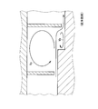
- Fig. 9 shows a conventional labyrinth seal.
- the vortex Va and the vortex Vb are formed in the space between the fins, thereby reducing the amount of fluid leakage.
- the shape of the vortex Vb is flat, and there is a limit to fluid energy loss due to the vortex Vb, and there is room for improvement in this respect.
- an object of the present invention is to provide a labyrinth seal capable of suppressing the amount of fluid leakage.
- the labyrinth seal is provided on the rotating machine.
- the rotating machine includes a first member, a second member facing the first member, and a gap formed between the first member and the second member.
- the gap is configured such that a fluid flows from a high pressure side to a low pressure side in a flow direction that is a direction orthogonal to a direction in which the first member and the second member face each other.
- the facing direction which is the direction in which the first member and the second member face each other
- the side from the second member toward the first member is one side in the facing direction, and in the facing direction, the first member is moved from the first member to the first member.
- the side facing the two members is the other side in the opposing direction.
- the labyrinth seal includes a step portion, a high-pressure side fin, a low-pressure side fin, and an annular groove.
- the step portion is formed on one side of the second member in the opposing direction.
- the high-pressure side fin extends from the other side portion in the facing direction of the first member on the high pressure side than the stepped portion to the other side in the facing direction.
- the low-pressure side fin extends from the other side portion in the facing direction of the first member on the lower pressure side than the stepped portion to the other side in the facing direction.
- the annular groove is formed on one side of the second member in the opposing direction.
- the stepped portion is arranged such that the portion of the second member on the low pressure side of the stepped portion is arranged on the other side in the opposing direction than the portion of the second member on the high pressure side of the stepped portion. Composed.
- the annular groove is disposed in at least a part of a region on the low pressure side of the stepped portion and on the high pressure side of the low pressure side fin.
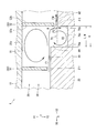
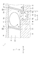
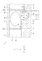
- FIG. 3 is a diagram corresponding to FIG. 2 of the second embodiment. It is FIG. 2 equivalent figure of 3rd Embodiment.
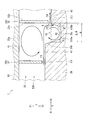
- FIG. 9 is a diagram corresponding to FIG. 2 of a fourth embodiment.
- FIG. 10 is a diagram corresponding to FIG. 2 of the fifth embodiment. It is FIG. 2 equivalent view of 6th Embodiment. It is sectional drawing which shows the conventional labyrinth seal.
- the rotary machine 1 (fluid machine, fluid rotary machine) is, for example, a compressor, such as a turbo compressor.
- the rotary machine 1 may be an expander, for example, and may be an expansion turbine, for example.
- the rotating machine 1 is a centrifugal type.
- the rotating machine 1 includes a stationary body 10 (first member), a rotating body 20 (second member), a gap 25, a labyrinth seal 30, and a labyrinth seal 130.
- the stationary body 10 is a casing, for example.
- the stationary body 10 may be a member that is disposed in a casing and fixed to the casing, for example.
- the rotating body 20 is arranged inside the stationary body 10 and rotates around the rotation axis A (center axis) with respect to the stationary body 10.
- the rotating body 20 is, for example, an impeller.
- the rotating body 20 faces the stationary body 10.
- the gap 25 is formed between the stationary body 10 and the rotating body 20, and the opposite direction Y2 (described below) portion of the stationary body 10 and the opposing direction one side Y1 ( Formed below) part.
- a fluid can flow through the gap 25.
- the gap 25 is configured such that fluid flows from the high pressure side X1 in the flow direction X to the low pressure side X2 in the flow direction X.
- the flow direction X is a direction orthogonal to the rotation axis A or a direction substantially orthogonal.
- the high pressure side X1 is a side far from the rotation axis A (radially outside with respect to the rotation axis A), and the low pressure side X2 is a side close to the rotation axis A (the rotation axis A). (Inner radial direction).
- the high pressure side X1 is a side close to the rotation axis A
- the low pressure side X2 is a side far from the rotation axis A.
- a direction in which the stationary body 10 and the rotating body 20 face each other is referred to as a facing direction Y.
- the facing direction Y is a direction orthogonal to the flow direction X.
- the facing direction Y is equal to (or substantially equal to) the direction of the rotation axis A.
- the side from the rotating body 20 toward the stationary body 10 is defined as the facing direction one side Y1
- the side from the stationary body 10 toward the rotating body 20 is defined as the facing direction other side Y2.
- a region (between in the flow direction X) between the high pressure side fin 51 (described below) and the low pressure side fin 52 (described below) is defined as a space 25a.
- the labyrinth seal 30 suppresses fluid leakage in the gap 25 from the high pressure side X1 to the low pressure side X2, as shown in FIG.
- the labyrinth seal 30 suppresses fluid leakage in the rotating machine 1 by suppressing this leakage.
- the labyrinth seal 30 is a device that suppresses the amount of fluid leakage flow (hereinafter also referred to as a leakage amount) without bringing the stationary body 10 and the rotating body 20 into contact (without contact).
- the labyrinth seal 30 includes a plurality of unit structures 30a.
- the plurality of unit structures 30a are configured similarly to each other. Hereinafter, one unit structure 30a will be described.
- the labyrinth seal 30 (each of the plurality of unit structures 30a) includes a stepped portion 40, a fin 50, and an annular groove 70 as shown in FIG.
- the stepped portion 40 is formed on the Y1 portion on the one side in the facing direction of the rotating body 20.
- the stepped portion 40 has a descending step structure. Specifically, the stepped portion 40 has a portion on the low pressure side X2 from the step portion 40 in the rotating body 20 (low pressure side) than a portion on the high pressure side X1 from the stepped portion 40 in the rotating body 20 (high pressure side stepped portion 41).
- the side step portion 42) is configured to be disposed on the other side Y2 in the opposite direction.
- the step portion 40 is connected to the low pressure side X2 end of the high pressure side step portion 41.
- the stepped portion 40 is connected to the high pressure side X1 end portion of the low pressure side stepped portion 42 via the annular groove 70.
- the step portion 40 has an annular shape (ring shape) around the rotation axis A (see FIG. 1).
- a section of the rotary machine 1 on a plane parallel to the rotation axis A including the rotation axis A is referred to as a “rotation axis section”.
- the rotational axis cross section is a cross section viewed from the direction orthogonal to the facing direction Y and the flow direction X.
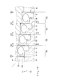
- FIG. 1 and FIG. 2 are diagrams showing the rotary machine 1 in the cross section of the rotary shaft.
- the stepped portion 40 has a linear shape extending in the facing direction Y in the cross section of the rotation axis. That is, the step portion 40 has an annular cylindrical shape with the rotation axis A as the center.
- the stepped portion 40 may be a straight line inclined with respect to the facing direction Y (see the stepped portion 540 shown in FIG. 7).
- the stepped portion 540 (see FIG. 7) is an annular curved surface having the rotation axis A as the center and a curved surface of the outer peripheral portion of the truncated cone having the rotation axis A as the center.
- the stepped portion 40 may be curved (not shown).
- the stepped portion 40 has an annular curved surface with the rotation axis A as the center. The same is true for the fin 50 and the annular groove 70 in that it is annular as described above.
- the high-pressure side step portion 41 is formed on the Y1 portion on the one side in the facing direction of the rotating body 20.
- the high-pressure side step portion 41 has a linear shape extending in the flow direction X. That is, the high-pressure side step portion 41 has an annular flat shape centering on the rotation axis A.
- the high-pressure side step portion 41 may have a portion (straight line or curved line) inclined with respect to the flow direction X. In this case, the high-pressure side step portion 41 has an annular curved surface shape (for example, a substantially planar shape) centered on the rotation axis A.
- the low-pressure side step part 42 is arranged on the low-pressure side X2 from the high-pressure side step part 41, and is arranged on the other side Y2 in the opposite direction from the high-pressure side step part 41.
- the shape of the low-pressure side step portion 42 is the same as the shape of the high-pressure side step portion 41.
- the fin 50 is a part that partitions the gap 25 and forms a space 25a.
- the fin 50 is disposed so as to narrow the gap 25 without completely partitioning the gap 25.
- the fin 50 extends from the opposite direction other side Y2 portion of the stationary body 10 to the opposite direction other side Y2, and extends to the vicinity of the opposite direction one side Y1 portion of the rotating body 20.
- the fin 50 is provided integrally with the stationary body 10.
- the fins 50 may be separate from the stationary body 10.
- the fin 50 includes a high-pressure side fin 51 and a low-pressure side fin 52 in order from the high-pressure side X1 to the low-pressure side X2.
- the high-pressure side fin 51 is provided on the high-pressure side X1 from the stepped portion 40.
- the high-pressure side fin 51 is disposed at a position facing the high-pressure side step portion 41 in the facing direction Y.
- the low pressure side fin 52 is provided on the low pressure side X2 from the stepped portion 40.
- the low-pressure side fin 52 is disposed at a position facing the low-pressure side stepped portion 42 in the facing direction Y.
- the low-pressure fin 52 may be disposed at a position facing the annular groove 70 in the facing direction Y.
- the gap ⁇ 2 is an outlet / outlet of fluid from the space 25a.
- the position of the front end portion of the low-pressure side fin 52 in the facing direction Y is one side Y1 in the facing direction than the position in the facing direction Y of the surface of the high-pressure side stepped portion 41.
- the size of the gap ⁇ 2 in the facing direction Y is, for example, the same as or different from the size of the gap ⁇ 1 in the facing direction Y.
- the low-pressure side fin 52 includes a high-pressure side surface 52a that is a side surface of the high-pressure side X1, and a low-pressure side surface 52b that is a side surface of the low-pressure side X2.
- the high-pressure side surface 52a and the low-pressure side surface 52b are surfaces orthogonal to the flow direction X.
- the “orthogonal” includes substantially orthogonal (the same applies hereinafter).
- the annular groove 70 is a groove for allowing the vortex V2 to flow.
- the annular groove 70 is configured such that the vortex V ⁇ b> 2 flows into a space surrounded by the annular groove 70 (inside the annular groove 70).
- the annular groove 70 is formed in the Y1 portion on the one side in the facing direction of the rotating body 20.
- the annular groove 70 is recessed on the other side Y2 in the opposite direction from the surface of the low-pressure side step portion 42.
- the annular groove 70 is disposed in at least a part of the region on the low pressure side X2 from the stepped portion 40 and on the high pressure side X1 from the low pressure side fin 52. A part of the annular groove 70 may be disposed on the low pressure side X2 with respect to the high pressure side surface 52a.
- the flow direction X position (position in the flow direction X) of the one end Y1 end portion and the high pressure side X1 end portion of the annular groove 70 is any one of the following [position a1] to [position a2].
- [Position a1] The same position as the other side Y2 end and the low pressure side X2 end in the opposite direction of the stepped portion 40.
- [Position a2] Opposite direction other side Y2 end portion of stepped portion 40 and lower pressure side X2 than the low pressure side X2 end portion (not shown).
- the annular groove 70 is arranged on the low pressure side X2 from the position of the stepped portion 40.
- the position X in the flow direction of the one end Y1 and the end X2 in the opposite direction of the annular groove 70 is any one of the following [position b1] to [position b5].
- [Position b1] Higher pressure side X1 than the tip of the high pressure side surface 52a (the end of the other side Y2 in the opposite direction).
- [Position b2] The same (or substantially the same) flow direction X position as the tip of the high-pressure side surface 52a.
- [Position b4] The same position X in the flow direction as the tip of the low-pressure side surface 52b.
- [Position b5] The low pressure side X2 than the low pressure side surface 52b.
- the annular groove 70 has an annular shape centered on the rotation axis A (see FIG. 1).
- the shape of the portion surrounded by the annular groove 70 is a rectangular shape.
- the opposite direction one side Y1 end portion of the “portion surrounded by the annular groove 70” is indicated by a two-dot chain line.
- the annular groove 70 includes a high pressure side surface 70a that is a side surface of the high pressure side X1, a low pressure side surface 70b that is a side surface of the low pressure side X2, and a bottom surface 70c.
- the high-pressure side surface 70a and the low-pressure side surface 70b are surfaces orthogonal to the flow direction X.
- the bottom surface 70c is a surface of the Y2 portion on the other side of the annular groove 70 in the facing direction, and is a surface constituting the bottom of the annular groove 70 (the bottom when the surface of the low-pressure side step portion 42 is used as a reference).
- the bottom surface 70c is a surface orthogonal to the facing direction Y.
- the labyrinth seal 130 is configured in substantially the same manner as the labyrinth seal 30 as shown in FIG. Differences between the labyrinth seal 130 and the labyrinth seal 30 are as follows. As shown in FIG. 2, in the labyrinth seal 30, the fin 50 is provided in the stationary body 10, and the step portion 40 and the annular groove 70 are provided in the rotating body 20. On the other hand, in the labyrinth seal 130 (see FIG. 1), the rotating body 20 is provided with the fins 50, and the stationary body 10 is provided with the stepped portions 40 and the annular grooves 70.
- the “first member” is a member on which the fin 50 is provided.
- the first member is the stationary body 10 in the labyrinth seal 30 and the rotating body 20 in the labyrinth seal 130 (see FIG. 1).
- the “second member” is a member provided with the stepped portion 40 and the annular groove 70.
- the second member is the rotating body 20 in the labyrinth seal 30 and the stationary body 10 in the labyrinth seal 130 (see FIG. 1).
- the fluid flows through the gap 25 as follows.
- the fluid passes from the space on the high pressure side X1 than the high pressure side fin 51 through the gap ⁇ 1, enters the space 25a, and forms the main flow F1.
- the main flow F1 first goes straight (or substantially straight, the same applies hereinafter) along the surface of the high-pressure side step portion 41, and then, even if it moves away from the surface of the high-pressure side step portion 41, the low-pressure side X2 Go straight on.
- Part of the main flow F1 forms a vortex V1.
- the vortex V1 flows as follows. A part of the main flow F1 flows from the main flow F1 to the opposite direction one side Y1, and flows to the opposite direction one side Y1 substantially along the high-pressure side surface 52a. This flow flows to the high-pressure side X1 so as to be substantially along the surface of the stationary body 10 (end surface on the other side Y2 in the opposing direction), and to the other side Y2 in the opposing direction so as to be substantially along the side surface of the low-pressure side X2 of the high-pressure fin 51 Flows and merges with the mainstream F1.
- Part of the main flow F1 collides with the high-pressure side surface 52a and turns to the other side Y2 in the opposite direction.
- This flow branches at a branch point B into a branch flow F3 substantially along the low-pressure side surface 70b and a branch flow F4 toward the gap ⁇ 2.
- the branch flow F3 forms a vortex V2 that flows in the annular groove 70 and the like.
- the vortex V2 flows as follows.
- the branch flow F3 flows toward the other side Y2 in the opposing direction so as to substantially follow the low pressure side surface 70b, flows to the high pressure side X1 so as to substantially follow the bottom surface 70c, and moves to the one side Y1 in the opposing direction so as to follow the high pressure side surface 70a.
- Flowing. This flow joins the main flow F1, or flows to the low pressure side X2 in the vicinity of the main flow F1.
- the shape of the vortex V2 in the cross section of the rotation axis is substantially circular.
- the shape of the vortex V2 in the cross section of the rotating shaft may be a flat, substantially circular shape (substantially elliptical) having a width in the flow direction X wider than the width in the facing direction Y, and the width in the facing direction Y is wider than the width in the flow direction X.
- a wide, substantially circular shape may be used.
- the branch flow F4 passes through the gap ⁇ 2, flows to the low pressure side X2, and flows out (leaks) to the space on the low pressure side X2 from the space 25a.
- the wall surface can be regarded as a fluid having a zero flow velocity.
- the wall surface includes, for example, the surface of the annular groove 70 (the high-pressure side surface 70a, the bottom surface 70c, and the low-pressure side surface 70b).
- the distance G is a distance in the flow direction X between the stepped portion 40 and the tip of the low-pressure fin 52 and the high-pressure side X1 (for example, the shortest distance, the same applies hereinafter).
- the stepped portion 40 has a width in the flow direction X (see, for example, the stepped portion 540 shown in FIG. 7)
- the starting point on the high pressure side X1 of the distance G is the opposite end of the stepped portion 40 on the other side Y2 and the low pressure side X2. It is an end (see FIG. 7) (the same applies to the distance L).
- the distance G is the distance in the flow direction X between the stepped portion 40 and the high-pressure side surface 52a.
- the distance L is a distance in the flow direction X between the stepped portion 40 and one end Y1 end portion and the low pressure side X2 end portion of the annular groove 70 in the facing direction. In the present embodiment, the distance L is a distance in the flow direction X between the stepped portion 40 and the low-pressure side surface 70b.
- the opening width W is the width in the flow direction X of the opening of the annular groove 70. More specifically, the opening width W is a width in the flow direction X at the end portion Y1 on the one side in the facing direction of the annular groove 70. In the present embodiment, the opening width W and the distance L are equal. Therefore, “distance L” can be read as “opening width W” with respect to the preferable conditions regarding the distance L described below.
- the distance G and the distance L were investigated by CFD (computational fluid dynamics) analysis.
- CFD computational fluid dynamics
- the distance G when the distance G is equal to the distance L is set to 1.
- 3 is a labyrinth seal that does not include the annular groove 70 shown in FIG.
- the amount of leakage decreases as the low-pressure fin 52 approaches the stepped portion 40, that is, as the distance G decreases.
- the unit of the leakage amount on the vertical axis is made dimensionless.
- the distance G when the distance G is equal to the distance L is set to 1
- the relationship between the distance G and the leakage amount shown in FIG. 3 is the relationship between the G / L and the leakage amount. equal. Therefore, in the present embodiment, G on the horizontal axis of the graph shown in FIG. 3 can be replaced with G / L.
- the distance L shown in FIG. 2 is too smaller than the distance G, that is, if the low-pressure side surface 70b of the annular groove 70 is too far from the high-pressure side X1 with respect to the high-pressure side surface 52a of the fin 50, there is the following problem. .
- the fluid at the branch point B more specifically, the fluid that is turned from the low pressure side X2 to the other side Y2 by the low pressure side fin 52 is less likely to flow into the annular groove 70. Therefore, since the flow rate of the branch flow F4 increases, the effect of suppressing the leakage amount is reduced.
- the gap ⁇ 2 between the tip of the low-pressure side fin 52 and the low-pressure side stepped portion 42 is increased, so that the fluid easily passes through the gap ⁇ 2, and the effect of suppressing the leakage amount is reduced.
- G / L is about 0.8 to 1 (0.8 or more and 1 or less). More preferably, the position of the low-pressure side surface 70b in the flow direction X and the position of the high-pressure side surface 52a in the flow direction X are substantially the same position.
- the effects of the labyrinth seal 30 shown in FIG. 2 are as follows.
- the labyrinth seal 30 is provided in the rotary machine 1.
- the rotating machine 1 includes a stationary body 10, a rotating body 20 that faces the stationary body 10, and a gap 25.
- the gap 25 is formed between the stationary body 10 and the rotating body 20 and is configured such that fluid flows in the flow direction X from the high pressure side X1 to the low pressure side X2.
- the flow direction X is a direction orthogonal to the direction in which the stationary body 10 and the rotating body 20 face each other.
- the labyrinth seal 30 includes a stepped portion 40, a high-pressure side fin 51, a low-pressure side fin 52, and an annular groove 70.
- the step portion 40 is formed on the Y1 portion on the one side in the facing direction of the rotating body 20.
- the high-pressure side fin 51 extends from the opposite direction other side Y2 portion of the stationary body 10 on the high-pressure side X1 than the stepped portion 40 to the opposite direction other side Y2.
- the low-pressure-side fin 52 extends from the opposite-direction other-side Y2 portion of the stationary body 10 on the low-pressure side X2 relative to the stepped portion 40 to the opposite-direction other side Y2.
- the annular groove 70 is formed in the Y1 portion on the one side of the rotating body 20 in the facing direction.
- the stepped portion 40 is a portion of the rotating body 20 on the high pressure side X1 from the stepped portion 40 (high pressure side stepped portion 41), and a portion of the rotating body 20 on the low pressure side X2 from the stepped portion 40 ( The low-pressure side step portion 42) is configured to be disposed on the other side Y2 in the opposite direction.
- the annular groove 70 is disposed in at least a part of the region on the low pressure side X2 from the stepped portion 40 and the high pressure side X1 from the low pressure side fin 52.
- the labyrinth seal 30 mainly includes the low-pressure fin 52 of [Configuration 1-1] and the stepped portion 40 of [Configuration 1-3]. Therefore, the vortex V ⁇ b> 2 is generated on the low pressure side X ⁇ b> 2 from the step portion 40 and on the high pressure side X ⁇ b> 1 than the low pressure side fin 52. Therefore, the labyrinth seal 30 includes the annular groove 70 of the above [Configuration 1-2] and [Configuration 1-4]. Accordingly, the vortex V2 flows into the annular groove 70. Therefore, the vortex V2 can be increased, the flow rate of the vortex V2 can be increased, and the flow velocity of the vortex V2 can be increased as compared with the case without the annular groove 70 (see FIG. 9). Therefore, the friction between the fluids of the vortex V2 and the periphery thereof can be increased, so that the energy loss of the fluid can be increased. As a result, fluid leakage in the gap 25 can be suppressed.
- the labyrinth seal 30 mainly includes the above [Configuration 1-1] and [Configuration 1-3]. Therefore, the main flow F1 branches at the branch point B into a branch flow F3 and a branch flow F4.
- the labyrinth seal 30 includes the annular groove 70 of the above [Configuration 1-2] and [Configuration 1-4]. Therefore, the flow that flows to the other side Y2 in the opposite direction at the branch point B easily flows into the annular groove 70 (the amount of the branch flow F3 is easily increased). Therefore, since the amount of the flow (branch flow F4) from the branch point B toward the gap ⁇ 2 can be suppressed, fluid leakage in the gap 25 can be suppressed.
- the annular groove 70 is formed widely on the high-pressure side X1 to the limit. Therefore, since the volume of the annular groove 70 can be increased, the vortex V2 can be increased. Therefore, since the energy loss of the fluid in the vortex V2 can be further increased, the fluid leakage in the gap 25 can be further suppressed.
- the distal end portion of the low pressure side fin 52 is disposed on the high pressure side X1 with respect to the base end portion (one side Y1 end portion in the opposite direction) of the low pressure side fin 52.
- the low pressure side X2 end portion of the distal end portion of the low pressure side fin 52 is disposed closer to the high pressure side X1 than the high pressure side X1 end portion of the base end portion of the low pressure side fin 52.
- the low-pressure side fin 52 is linear
- the high-pressure side surface 52a is linear
- the low-pressure side surface 52b is linear.
- the high-pressure side surface 52a is inclined with respect to the facing direction Y by an angle ⁇ 2.
- the low-pressure fin 52 may have a curved shape or a bent shape such as an L shape (the same applies to the high-pressure fin 51). Further, the low-pressure side surface 52b may be inclined with respect to the facing direction Y (for example, the angle ⁇ 2) or may not be inclined with respect to the facing direction Y.
- the high pressure side fin 51 is configured in the same manner as the low pressure side fin 52.
- the side surface of the high-pressure side fin 51 on the high-pressure side X1 is inclined with respect to the facing direction Y by an angle ⁇ 1.
- the angle ⁇ 1 may be equal to or different from the angle ⁇ 2. Further, either the angle ⁇ 1 or the angle ⁇ 2 may be 0 °.
- the angle ⁇ 2 is larger than 0 ° will be described.
- the fluid (fluid at the branch point B) turned from the low pressure side X2 to the other side Y2 by the low pressure side fin 52 easily flows to the high pressure side X1 while flowing to the other side Y2 in the opposite direction. Therefore, the amount of the branch flow F4 toward the low pressure side X2 can be suppressed, and the amount of the branch flow F3 (vortex V2) flowing into the annular groove 70 can be increased.
- the main flow F1 flowing toward the low-pressure side X2 toward the low-pressure side fin 52 hits the low-pressure side fin 52, tends to flow to the one side Y1 in the facing direction (easily forms the vortex V1), and hardly flows to the other side Y2 in the facing direction. Therefore, the quantity of the branch flow F3 and the branch flow F4 can be suppressed. As a result, fluid leakage in the gap 25 can be further suppressed.
- Arc-shaped portion 370 d is provided at the bottom of annular groove 70.
- the cross section of the arc-shaped portion 370d in the rotary shaft cross section is an arc shape protruding to the other side Y2 in the facing direction.
- the cross section of the arc-shaped portion 370d in the cross section of the rotation axis is an arc shape and a semicircular arc shape (the central angle of the arc is 180 °).
- the central angle of the arc may be less than 180 °.
- the “arc shape” includes a substantially arc shape (for example, a substantially semicircular arc shape).
- the cross section of the arc-shaped portion 370d in the cross section of the rotation axis may be elliptical arc shape (curved shape constituting a part of the ellipse) or semi-elliptical arc shape.
- the “elliptical arc shape” includes a substantially elliptic arc shape (for example, a substantially semi-elliptical arc shape).
- the high-pressure side surface 70a (see FIG. 2) and the low-pressure side surface 70b (see FIG. 2) are provided so as to be continuous with the arc-shaped portion 370d. When the arc-shaped portion 370d is provided, the high-pressure side surface 70a and the low-pressure side surface 70b may not be provided.
- the shape of the annular groove 70 is closer to the shape of the flow of the vortex V2 than when the inside of the annular groove 70 is rectangular in the cross section of the rotating shaft (see FIG. 2). Therefore, since the vortex V ⁇ b> 2 flows along the bottom of the annular groove 70, it is possible to suppress a decrease in the flow velocity of the vortex V ⁇ b> 2 in the annular groove 70. Therefore, since the energy loss in the vortex V2 can be further increased, fluid leakage in the gap 25 can be further suppressed.
- the difference between the labyrinth seal 430 of the fourth embodiment and the first embodiment will be described with reference to FIG.
- the difference is the shape of the annular groove 70.
- the annular groove 70 includes a low-pressure side inclined portion 470b (inclined portion).
- the low-pressure side inclined portion 470b is provided in the low-pressure side X2 portion of the annular groove 70.
- the opposite direction other side Y2 end of the low pressure side inclined portion 470b is arranged on the high pressure side X1 (center side of the annular groove 70 in the flow direction X) than the opposite direction one side Y1 end of the low pressure side inclined portion 470b.
- the low-pressure side inclined portion 470b is linear and is inclined with respect to the facing direction Y by an angle ⁇ 1.
- the low-pressure side inclined portion 470b may not be linear but may be curved.
- the annular groove 70 includes a low-pressure side inclined portion 470b provided in the low-pressure side X2 portion of the annular groove 70.
- the opposite direction other side Y2 end portion of the low pressure side inclined portion 470b is disposed closer to the center side (high pressure side X1) of the annular groove 70 in the flow direction X than the opposite direction one side Y1 end portion of the low pressure side inclined portion 470b. .
- the shape of the annular groove 70 is closer to the shape of the flow of the vortex V2 than when the inside of the annular groove 70 is rectangular in the cross section of the rotation axis (see FIG. 2). Therefore, since the flow of the vortex V2 flows along the low-pressure side inclined portion 470b, it is possible to suppress the flow velocity of the vortex V2 from being lowered in the annular groove 70. Therefore, since the energy loss in the vortex V2 can be further increased, fluid leakage in the gap 25 can be further suppressed.
- the difference between the labyrinth seal 530 of the fifth embodiment and the fourth embodiment will be described with reference to FIG.
- the difference is the shape of the stepped portion 540 and the annular groove 70.
- the annular groove 70 includes a high-pressure side inclined portion 570a (inclined portion).
- the high-pressure side inclined portion 570a is provided in the high-pressure side X1 portion of the annular groove 70.
- the opposite side Y2 end portion of the high pressure side inclined portion 570a in the opposite direction is disposed on the low pressure side X2 (center side in the flow direction X of the annular groove 70) than the opposite direction one side Y1 end portion of the high pressure side inclined portion 570a.
- the high-pressure side inclined portion 570a is linear, and is inclined by the angle ⁇ 2 with respect to the facing direction Y.
- the angle ⁇ 2 may be equal to or different from the angle ⁇ 1.
- the high-pressure side inclined portion 570a may not be linear but may be curved.
- only one of the high-pressure side inclined portion 570a and the low-pressure side inclined portion 470b may be provided (one of the angle ⁇ 1 and the angle ⁇ 2 may be 0 °).
- the step portion 540 is inclined by the angle ⁇ 2 with respect to the facing direction Y, similarly to the high-pressure side inclined portion 570a.
- the step portion 540 and the high-pressure side inclined portion 570a are continuous in a straight line.
- the annular groove 70 includes a high-pressure side inclined portion 570a provided in the high-pressure side X1 portion of the annular groove 70.
- the opposite side Y2 end of the high pressure side inclined portion 570a is disposed closer to the center side (low pressure side X2) of the annular groove 70 in the flow direction X than the opposite direction one side Y1 end of the high pressure side inclined portion 570a.
- the labyrinth seal 630 includes a plurality of unit structures 30a as in the first embodiment.
- the plurality of unit structures 30a are adjacent to each other in the flow direction X and are arranged continuously (side by side) in the flow direction X.
- the low-pressure side step 42 of the unit structure 30a on the high-pressure side X1 is also the high-pressure side step 41 of the unit structure 30a on the low-pressure side X2.
- the high-pressure side step portion 41, the step portion 40, and the low-pressure side step portion 42 of the plurality of unit structures 30a constitute a staircase structure that is gradually arranged from the high-pressure side X1 to the low-pressure side X2 and on the other side Y2. .
- the low-pressure side fin 52 of the unit structure 30a on the high-pressure side X1 is also the high-pressure side fin 51 of the unit structure 30a on the low-pressure side X2.
- the number of unit structures 30a may be four as in the labyrinth seal 130 of FIGS. 8 and 1, may be five as in the labyrinth seal 30 of FIG. 1, may be three or less, and may be six or more.
- Each unit structure 30a may be modified as in any one of the second to fifth embodiments.
- the effects of the labyrinth seal 630 shown in FIG. 8 are as follows.
- the labyrinth seal 630 includes a plurality of unit structures 30a adjacent to each other in the flow direction X.
- Each of the plurality of unit structures 30 a includes a stepped portion 40, a high-pressure side fin 51, a low-pressure side fin 52, and an annular groove 70.
- each of the above embodiments may be variously modified. Some of the components of the above embodiment may not be provided. The number of components in the above embodiment may be changed. Components of different embodiments may be combined. For example, as illustrated in FIG. 5, at least one of the high-pressure side inclined portion 570 a and the low-pressure side inclined portion 470 b illustrated in FIG. 7 may be added to the annular groove 70 including the arc-shaped portion 370 d.
- the step portion 540 may be inclined with respect to the facing direction Y as shown in FIG.
- the inclination of the stepped portion 40 with respect to the facing direction Y may be different from the angle ⁇ 2, and the step as shown in FIG.
- the portion 40 may coincide with the facing direction Y.
- the low-pressure side surface 52b may be different from the angle ⁇ 2 of the high-pressure side surface 52a with respect to the facing direction Y and the angle of the low-pressure side surface 52b with respect to the facing direction Y.
- the high-pressure side surface 52a when the high-pressure side surface 52a extends in the facing direction Y, as shown in FIG. 4, the low-pressure side surface 52b may be inclined with respect to the facing direction Y (see FIG. 1). .
- the opposing direction Y and the flow direction X may be directions inclined with respect to the rotation axis A.
- the facing direction Y may be orthogonal to the rotation axis A.
- the flow direction X may be parallel to the rotation axis A.
- Rotating machine 10 Stationary body (first member or second member) 20 Rotating body (second member or first member) 25 Gap 30, 130, 230, 330, 430, 530, 630 Labyrinth seal 30a Unit structure 40, 540 Stepped portion 51 High-pressure side fin 52 Low-pressure side fin 70 Annular groove 370d Arc-shaped portion 470b Low-pressure side inclined portion (inclined portion) 570a High-pressure side inclined part (inclined part) X Flow direction X1 High pressure side X2 Low pressure side Y Opposite direction Y1 Opposite direction one side Y2 Opposite direction other side
Landscapes
- Engineering & Computer Science (AREA)
- General Engineering & Computer Science (AREA)
- Mechanical Engineering (AREA)
- Structures Of Non-Positive Displacement Pumps (AREA)
- Sealing Using Fluids, Sealing Without Contact, And Removal Of Oil (AREA)
Abstract
流体の漏れ量を抑制することができる。高圧側フィン(51)は、段差部(40)よりも高圧側(X1)に設けられる。低圧側フィン(52)は、段差部(40)よりも低圧側(X2)に設けられる。環状溝(70)は、回転体(20)の対向方向一方側(Y1)部分に形成される。段差部(40)は、回転体(20)のうち段差部(40)より高圧側(X1)の部分である高圧側段部(41)よりも、回転体(20)のうち段差部(40)より低圧側(X2)の部分である低圧側段部(42)の方が、対向方向他方側(Y2)に配置されるように構成される。環状溝(70)は、段差部(40)よりも低圧側(X2)かつ低圧側フィン(52)よりも高圧側(X1)の領域の少なくとも一部に配置される。
Description
本発明は、ラビリンスシールに関する。
例えば特許文献1、2に従来のラビリンスシールが開示されている。このラビリンスシールは、回転機械を構成する2つの部材(例えば回転体と静止体)の間の隙間から流体が漏れることを抑制するものである。特許文献2に記載のラビリンスシールは、段差部と、複数のフィンと、を備えている。この構成により、フィンの間の空間に渦を発生させ、流体のエネルギー損失を生じさせることで、流体の漏れ量を抑制している。
図9に従来のラビリンスシールを示す。従来のラビリンスシールでは、フィンの間の空間に渦Vaおよび渦Vbが形成されることによって、流体の漏れ量の低減が図られている。しかし、渦Vbの形状は扁平状となっており、渦Vbによる流体のエネルギー損失には限界があり、この点において改善の余地があった。
そこで本発明は、流体の漏れ量を抑制できるラビリンスシールを提供することを目的とする。
ラビリンスシールは、回転機械に設けられる。前記回転機械は、第1部材と、前記第1部材に対向する第2部材と、前記第1部材と前記第2部材との間に形成される隙間と、を備える。前記隙間は、前記第1部材と前記第2部材とが対向する方向に直交する方向である流れ方向に高圧側から低圧側に流体が流れるように構成される。前記第1部材と前記第2部材とが対向する方向である対向方向において、前記第2部材から前記第1部材に向かう側を対向方向一方側とし、対向方向において、前記第1部材から前記第2部材に向かう側を対向方向他方側とする。ラビリンスシールは、段差部と、高圧側フィンと、低圧側フィンと、環状溝と、を備える。前記段差部は、前記第2部材の対向方向一方側部分に形成される。前記高圧側フィンは、前記段差部よりも高圧側における前記第1部材の対向方向他方側部分から対向方向他方側に延びる。前記低圧側フィンは、前記段差部よりも低圧側における前記第1部材の対向方向他方側部分から対向方向他方側に延びる。前記環状溝は、前記第2部材の対向方向一方側部分に形成される。前記段差部は、前記第2部材のうち前記段差部より高圧側の部分よりも、前記第2部材のうち前記段差部より低圧側の部分の方が、対向方向他方側に配置されるように構成される。前記環状溝は、前記段差部よりも低圧側かつ前記低圧側フィンよりも高圧側の領域の少なくとも一部に配置される。
上記構成により、流体の漏れ量を抑制できる。
(第1実施形態)
図1~図3を参照して第1実施形態の回転機械1について説明する。
図1~図3を参照して第1実施形態の回転機械1について説明する。
回転機械1(流体機械、流体回転機械)は、例えば圧縮機であり、例えばターボ圧縮機などである。回転機械1は、例えば膨張機でもよく、例えば膨張タービンなどでもよい。回転機械1は、遠心式である。回転機械1は、静止体10(第1部材)と、回転体20(第2部材)と、隙間25と、ラビリンスシール30と、ラビリンスシール130と、を備える。静止体10は、例えばケーシングである。静止体10は、例えば、ケーシング内に配置され、ケーシングに固定される部材でもよい。
回転体20は、静止体10の内部に配置され、静止体10に対して回転軸A(中心軸)回りに回転する。回転体20は、例えばインペラである。回転体20は、静止体10に対向する。回転体20のうち、ラビリンスシール30およびラビリンスシール130が設けられる部分は、静止体10と対向する。
隙間25は、図2に示すように、静止体10と回転体20との間に形成され、静止体10の対向方向他方側Y2(下記)部分と、回転体20の対向方向一方側Y1(下記)部分との間に形成される。隙間25を流体が流れることが可能である。流れ方向Xの高圧側X1から、流れ方向Xの低圧側X2に、隙間25を流体が流れるように、隙間25が構成される。図1に示すように、流れ方向Xは、回転軸Aに直交する方向、または略直交する方向である。回転機械1が圧縮機の場合、高圧側X1は、回転軸Aから遠い側(回転軸Aを基準とした径方向外側)であり、低圧側X2は、回転軸Aに近い側(回転軸Aを基準とした径方向内側)である。回転機械1が膨張機の場合、高圧側X1は回転軸Aに近い側であり、低圧側X2は回転軸Aから遠い側である。以下では回転機械1が圧縮機の場合について説明する。静止体10と回転体20とが対向する方向を対向方向Yとする。対向方向Yは、流れ方向Xと直交する方向である。対向方向Yは、回転軸Aの方向と等しい(またはほぼ等しい)。図2に示すように、対向方向Yにおいて、回転体20から静止体10に向かう側を対向方向一方側Y1とし、静止体10から回転体20に向かう側を対向方向他方側Y2とする。隙間25のうち、高圧側フィン51(下記)と低圧側フィン52(下記)との間の領域(流れ方向Xにおける間)を、空間25aとする。
ラビリンスシール30は、図1に示すように、高圧側X1から低圧側X2への、隙間25での流体の漏れを抑制する。ラビリンスシール30は、この漏れを抑制することで、回転機械1内での流体の循環を抑制する。ラビリンスシール30は、静止体10と回転体20とを接触させることなく(非接触で)、流体の漏れ流れの量(以下、漏れ量ともいう)を抑制する装置である。ラビリンスシール30は、複数の単位構造30aを備える。複数の単位構造30aは、互いに同様に構成される。以下では1つの単位構造30aについて説明する。ラビリンスシール30は(複数の単位構造30aそれぞれは)、図2に示すように、段差部40と、フィン50と、環状溝70と、を備える。
段差部40は、回転体20の対向方向一方側Y1部分に形成される。段差部40は、いわば降段構造である。具体的には、段差部40は、回転体20のうち段差部40より高圧側X1の部分(高圧側段部41)よりも、回転体20のうち段差部40より低圧側X2の部分(低圧側段部42)の方が、対向方向他方側Y2に配置されるように構成される。段差部40は、高圧側段部41の低圧側X2端部につながれる。段差部40は、環状溝70を介して、低圧側段部42の高圧側X1端部につながれる。
この段差部40は、回転軸A(図1参照)を中心とした環状(リング状)である。回転軸Aを含む回転軸Aと平行な平面での、回転機械1の断面を「回転軸断面」とする。回転軸断面は、対向方向Yおよび流れ方向Xそれぞれに直交する方向から見た断面である。図1および図2は、回転軸断面における回転機械1を示す図である。図2に示すように、回転軸断面において、段差部40は、対向方向Yに延びる直線状である。すなわち、段差部40は、回転軸Aを中心とする環状の円筒状である。回転軸断面において、段差部40は、対向方向Yに対して傾斜する直線状でもよい(図7に示す段差部540参照)。この場合、段差部540(図7参照)は、回転軸Aを中心とする環状の曲面状であって、回転軸Aを中心とする円錐台の外周部の曲面状である。回転軸断面において、段差部40は、曲線状でもよい(図示なし)。この場合、段差部40は、回転軸Aを中心とする環状の曲面状である。上記のような環状である点は、フィン50および環状溝70についても同様である。
高圧側段部41は、回転体20の対向方向一方側Y1部分に形成される。回転軸断面において、高圧側段部41は、流れ方向Xに延びる直線状である。すなわち、高圧側段部41は、回転軸Aを中心とする環状の平面状である。回転軸断面において、高圧側段部41は、流れ方向Xに対して傾斜する部分(直線または曲線)を有してもよい。この場合、高圧側段部41は、回転軸Aを中心とする環状の曲面状(例えば略平面状)である。
低圧側段部42は、高圧側段部41よりも低圧側X2に配置され、高圧側段部41よりも対向方向他方側Y2に配置される。低圧側段部42の形状は、高圧側段部41の形状と同様である。
フィン50は、隙間25を仕切り、空間25aを形成する部分である。フィン50は、隙間25を完全には仕切らず、隙間25を狭めるように配置される。フィン50は、静止体10の対向方向他方側Y2部分から対向方向他方側Y2に延び、回転体20の対向方向一方側Y1部分の近傍まで延びる。フィン50は、静止体10と一体的に設けられる。フィン50は、静止体10と別体でもよい。フィン50は、高圧側X1から低圧側X2の順に、高圧側フィン51と、低圧側フィン52と、を備える。
高圧側フィン51は、段差部40よりも高圧側X1に設けられる。高圧側フィン51は、高圧側段部41と対向方向Yに対向する位置に配置される。高圧側フィン51の先端部(対向方向他方側Y2端部)と、高圧側段部41の表面(対向方向一方側Y1端面)と、の間には、対向方向Yの隙間δ1がある。さらに詳しくは、高圧側フィン51の先端部の対向方向Yにおける位置は、低圧側段部42の表面(対向方向一方側Y1端面)の対向方向Yにおける位置よりも、対向方向一方側Y1である。
低圧側フィン52は、段差部40よりも低圧側X2に設けられる。低圧側フィン52は、低圧側段部42と対向方向Yに対向する位置に配置される。低圧側フィン52は、環状溝70と対向方向Yに対向する位置に配置されてもよい。低圧側フィン52の先端部と、低圧側段部42の表面と、の間には、対向方向Yの隙間δ2がある。隙間δ2は、空間25aからの流体の流出出口である。低圧側フィン52の先端部の対向方向Yにおける位置は、高圧側段部41の表面の対向方向Yにおける位置よりも、対向方向一方側Y1である。隙間δ2の対向方向Yにおける大きさは、隙間δ1の対向方向Yにおける大きさと、例えば同じであり、異なってもよい。低圧側フィン52は、高圧側X1の側面である高圧側側面52aと、低圧側X2の側面である低圧側側面52bと、を備える。高圧側側面52aおよび低圧側側面52bは、流れ方向Xに直交する面である。上記「直交」は、略直交を含む(以下同様)。
環状溝70は、渦V2を流入させるための溝である。環状溝70は、環状溝70に囲まれた空間(環状溝70の内部)に渦V2が流入するように構成される。環状溝70は、回転体20の対向方向一方側Y1部分に形成される。環状溝70は、低圧側段部42の表面よりも対向方向他方側Y2に凹む。環状溝70は、段差部40よりも低圧側X2、かつ、低圧側フィン52よりも高圧側X1の領域の少なくとも一部に配置される。環状溝70の一部は、高圧側側面52aよりも低圧側X2に配置されてもよい。
この環状溝70の対向方向一方側Y1端部かつ高圧側X1端部の、流れ方向X位置(流れ方向Xにおける位置)は、次の[位置a1]~[位置a2]のいずれかである。[位置a1]段差部40の対向方向他方側Y2端部かつ低圧側X2端部と同じ位置。[位置a2]段差部40の対向方向他方側Y2端部かつ低圧側X2端部よりも低圧側X2(図示なし)。上記[位置a1]の場合、環状溝70は、段差部40の位置から低圧側X2に配置される。上記[位置a2]の場合、段差部40の対向方向他方側Y2端部かつ低圧側X2端部と、環状溝70の低圧側X2端部かつ対向方向一方側Y1端部と、の間に、流れ方向Xの間隔(低圧側段部42)が形成される。
この環状溝70の対向方向一方側Y1端部かつ低圧側X2端部の、流れ方向X位置は、次の[位置b1]~[位置b5]のいずれかである。[位置b1]高圧側側面52aの先端(対向方向他方側Y2の端)よりも高圧側X1。[位置b2]高圧側側面52aの先端と同じ(または略同じ)流れ方向X位置。[位置b3]高圧側側面52aの先端よりも低圧側X2、かつ、低圧側側面52bの先端よりも高圧側X1。[位置b4]低圧側側面52bの先端と同じ流れ方向X位置。[位置b5]低圧側側面52bよりも低圧側X2。
この環状溝70は、回転軸A(図1参照)を中心とする環状である。回転軸断面において、環状溝70に囲まれた部分(環状溝70の内部)の形状は、矩形状である。図2において、「環状溝70に囲まれた部分」の対向方向一方側Y1端部を二点鎖線で示す。環状溝70は、高圧側X1の側面である高圧側側面70aと、低圧側X2の側面である低圧側側面70bと、底面70cと、を備える。高圧側側面70aおよび低圧側側面70bは、流れ方向Xに直交する面である。底面70cは、環状溝70の対向方向他方側Y2部分の面であり、環状溝70の底部(低圧側段部42の表面を基準としたときの底部)を構成する面である。底面70cは、対向方向Yに直交する面である。
ラビリンスシール130は、図1に示すように、ラビリンスシール30とほぼ同様に構成される。ラビリンスシール30に対するラビリンスシール130の相違点は次の通りである。図2に示すように、ラビリンスシール30では、静止体10にフィン50が設けられ、回転体20に段差部40および環状溝70が設けられた。一方、ラビリンスシール130(図1参照)では、回転体20にフィン50が設けられ、静止体10に段差部40および環状溝70が設けられる。
(第1部材および第2部材について)
「第1部材」は、フィン50が設けられる部材である。第1部材は、ラビリンスシール30では静止体10であり、ラビリンスシール130(図1参照)では回転体20である。「第2部材」は、段差部40および環状溝70が設けられる部材である。第2部材は、ラビリンスシール30では回転体20であり、ラビリンスシール130(図1参照)では静止体10である。
「第1部材」は、フィン50が設けられる部材である。第1部材は、ラビリンスシール30では静止体10であり、ラビリンスシール130(図1参照)では回転体20である。「第2部材」は、段差部40および環状溝70が設けられる部材である。第2部材は、ラビリンスシール30では回転体20であり、ラビリンスシール130(図1参照)では静止体10である。
(流体の流れ)
流体は、次のように隙間25を流れる。流体は、高圧側フィン51よりも高圧側X1の空間から、隙間δ1を通り、空間25aに入り、主流F1を形成する。主流F1は、まず、高圧側段部41の表面に沿って、低圧側X2に直進(または略直進、以下同様)し、次に、高圧側段部41の表面から離れても、低圧側X2に直進する。
流体は、次のように隙間25を流れる。流体は、高圧側フィン51よりも高圧側X1の空間から、隙間δ1を通り、空間25aに入り、主流F1を形成する。主流F1は、まず、高圧側段部41の表面に沿って、低圧側X2に直進(または略直進、以下同様)し、次に、高圧側段部41の表面から離れても、低圧側X2に直進する。
主流F1の一部の流れは、渦V1を形成する。渦V1は、次のように流れる。主流F1の一部の流れが、主流F1から対向方向一方側Y1に分岐し、高圧側側面52aにほぼ沿うように対向方向一方側Y1に流れる。この流れが、静止体10の表面(対向方向他方側Y2の端面)にほぼ沿うように高圧側X1に流れ、高圧側フィン51の低圧側X2の側面にほぼ沿うように対向方向他方側Y2に流れ、主流F1に合流する。
主流F1の一部の流れは、高圧側側面52aに衝突し、対向方向他方側Y2に転向する。この流れは、分岐点Bで、低圧側側面70bにほぼ沿う分岐流F3と、隙間δ2に向かう分岐流F4と、に分岐する。
分岐流F3は、環状溝70内などを流れる渦V2を形成する。渦V2は、次のように流れる。分岐流F3が、低圧側側面70bにほぼ沿うように対向方向他方側Y2側に流れ、底面70cにほぼ沿うように高圧側X1に流れ、高圧側側面70aに沿うように対向方向一方側Y1に流れる。この流れが、主流F1に合流する、または主流F1の近傍で低圧側X2に流れる。回転軸断面における渦V2の形状は、略円形状である。回転軸断面における渦V2の形状は、対向方向Yの幅よりも流れ方向Xの幅が広い扁平な略円形状(略楕円形状)でもよく、流れ方向Xの幅よりも対向方向Yの幅が広い略円形状でもよい。
分岐流F4は、隙間δ2を通過し、低圧側X2に流れ、空間25aよりも低圧側X2の空間に流出する(漏れる)。
分岐流F3が環状溝70に流入することで、分岐流F4の流量が抑制されるので、空間25aからの流体の漏れ量が抑制される。また、渦V2によって流体間摩擦が発生し、流体のエネルギー損失が生じることによって、空間25aからの流体の漏れ量が抑制される。この流体間摩擦には、流体どうしの摩擦、および、流体と壁面との摩擦が含まれる。上記壁面は、流速がゼロの流体とみなせるものである。上記壁面には、例えば環状溝70の表面(高圧側側面70a、底面70c、および低圧側側面70b)などが含まれる。
(寸法について)
段差部40よりも低圧側X2かつ低圧側フィン52よりも高圧側X1の領域の少なくとも一部に環状溝70があれば、環状溝70による効果(漏れ量の抑制)が得られる。さらに、下記の条件を満たすことで環状溝70による効果をより向上させることができる。回転軸断面における、流れ方向Xに関する寸法には、距離Gと、距離Lと、開口幅Wと、がある。これらの寸法を次のように定義する。
段差部40よりも低圧側X2かつ低圧側フィン52よりも高圧側X1の領域の少なくとも一部に環状溝70があれば、環状溝70による効果(漏れ量の抑制)が得られる。さらに、下記の条件を満たすことで環状溝70による効果をより向上させることができる。回転軸断面における、流れ方向Xに関する寸法には、距離Gと、距離Lと、開口幅Wと、がある。これらの寸法を次のように定義する。
距離Gは、段差部40と、低圧側フィン52の先端部かつ高圧側X1端部と、の流れ方向Xにおける距離(例えば最短距離、以下同様)である。段差部40に流れ方向Xの幅がある場合(例えば図7に示す段差部540参照)は、距離Gの高圧側X1の起点は、段差部40の対向方向他方側Y2端部かつ低圧側X2端部とする(図7参照)(距離Lについても同様)。図2に示すように、本実施形態では、距離Gは、段差部40と、高圧側側面52aと、の流れ方向Xにおける距離である。
距離Lは、段差部40と、環状溝70の対向方向一方側Y1端部かつ低圧側X2端部と、の流れ方向Xにおける距離である。本実施形態では、距離Lは、段差部40と、低圧側側面70bと、の流れ方向Xにおける距離である。
開口幅Wは、環状溝70の開口の流れ方向Xにおける幅である。さらに詳しくは、開口幅Wは、環状溝70の対向方向一方側Y1端部での流れ方向Xにおける幅である。本実施形態では、開口幅Wと距離Lとは等しい。そのため、下記の距離Lに関する好ましい条件について、「距離L」を「開口幅W」に読み替えることができる。
CFD(computational fluid dynamics)解析により、距離Gおよび距離Lについて調査した。その結果、図3に示すように距離Gによって漏れ量が変化するという知見を得た。ここでは、図2に示す環状溝70の位置を変えずに(距離Lを変えずに)、距離Gを様々に変えたときの漏れ量を調査した。また、距離Gが距離Lと等しいときの距離Gを1とした。図3の「従来技術」は、図2に示す環状溝70を備えないラビリンスシールである。従来技術では、低圧側フィン52が段差部40に近づくほど、すなわち距離Gが小さくなるほど、漏れ量が小さくなる。図3に示すグラフでは、縦軸の漏れ量の単位を無次元化した。ここで、本実施形態については、距離Gが距離Lと等しいときの距離Gを1としたので、図3に示す距離Gと漏れ量との関係は、G/Lと漏れ量との関係と等しい。よって、本実施形態については、図3に示すグラフの横軸のGを、G/Lに置き換えることができる。
図2に示す距離Lが距離Gよりも小さすぎると、すなわち、フィン50の高圧側側面52aに対して、環状溝70の低圧側側面70bが高圧側X1に離れすぎると、次の問題がある。この場合、分岐点Bの流体、さらに詳しくは、低圧側フィン52によって低圧側X2から対向方向他方側Y2に転向した流体が、環状溝70に流入しにくくなる。そのため、分岐流F4の流量が増えるので、漏れ量抑制の効果は小さくなる。また、距離Lが距離Gよりも大きすぎると、すなわち、高圧側側面52aに対して低圧側側面70bが低圧側X2に離れすぎると、次の問題がある。この場合、低圧側フィン52の先端部と低圧側段部42との間の隙間δ2が大きくなるので、流体が隙間δ2を通りやすくなり、漏れ量抑制の効果は小さくなる。
そこで、図3に示すように、0.78<G/L、を満たすことが好ましい。この場合、従来技術に比べ、確実に漏れ量を抑制できる。また、G/Lを約0.8~1(0.8以上、1以下)とすることがさらに好ましい。低圧側側面70bの流れ方向Xにおける位置と高圧側側面52aの流れ方向Xにおける位置と、を略同位置にすることがさらに好ましい。G/Lを約0.8~1とすることで、G/Lが0.8未満または1を超える場合に比べ、漏れ量抑制効果を大きくすることができた。G/L<1.14としてもよい。上記の解析は、回転軸A(図1参照)側が低圧側X2、回転軸Aから遠い側が高圧側X1の場合(回転機械1が圧縮機の場合)について行ったものである。しかし、回転軸A側が高圧側X1、回転軸Aから遠い側が低圧側X2の場合(回転機械1が膨張機の場合)についても、ラビリンスシール30の構造が同様であれば、同様の結果が得られると考えられる。
(効果1)
図2に示すラビリンスシール30による効果は次の通りである。ラビリンスシール30は、回転機械1に設けられる。回転機械1は、静止体10と、静止体10に対向する回転体20と、隙間25と、を備える。隙間25は、静止体10と回転体20との間に形成され、流れ方向Xに高圧側X1から低圧側X2に流体が流れるように構成される。流れ方向Xは、静止体10と回転体20とが対向する方向に直交する方向である。静止体10と回転体20とが対向する方向である対向方向Yにおいて、回転体20から静止体10に向かう側を対向方向一方側Y1とし、静止体10から回転体20に向かう側を対向方向他方側Y2とする。ラビリンスシール30は、段差部40と、高圧側フィン51と、低圧側フィン52と、環状溝70と、を備える。段差部40は、回転体20の対向方向一方側Y1部分に形成される。高圧側フィン51は、段差部40よりも高圧側X1における静止体10の対向方向他方側Y2部分から、対向方向他方側Y2に延びる。
図2に示すラビリンスシール30による効果は次の通りである。ラビリンスシール30は、回転機械1に設けられる。回転機械1は、静止体10と、静止体10に対向する回転体20と、隙間25と、を備える。隙間25は、静止体10と回転体20との間に形成され、流れ方向Xに高圧側X1から低圧側X2に流体が流れるように構成される。流れ方向Xは、静止体10と回転体20とが対向する方向に直交する方向である。静止体10と回転体20とが対向する方向である対向方向Yにおいて、回転体20から静止体10に向かう側を対向方向一方側Y1とし、静止体10から回転体20に向かう側を対向方向他方側Y2とする。ラビリンスシール30は、段差部40と、高圧側フィン51と、低圧側フィン52と、環状溝70と、を備える。段差部40は、回転体20の対向方向一方側Y1部分に形成される。高圧側フィン51は、段差部40よりも高圧側X1における静止体10の対向方向他方側Y2部分から、対向方向他方側Y2に延びる。
[構成1-1]低圧側フィン52は、段差部40よりも低圧側X2における静止体10の対向方向他方側Y2部分から対向方向他方側Y2に延びる。
[構成1-2]環状溝70は、回転体20の対向方向一方側Y1部分に形成される。
[構成1-3]段差部40は、回転体20のうち段差部40より高圧側X1の部分(高圧側段部41)よりも、回転体20のうち段差部40より低圧側X2の部分(低圧側段部42)の方が、対向方向他方側Y2に配置されるように構成される。
[構成1-4]環状溝70は、段差部40よりも低圧側X2かつ低圧側フィン52よりも高圧側X1の領域の少なくとも一部に配置される。
[構成1-2]環状溝70は、回転体20の対向方向一方側Y1部分に形成される。
[構成1-3]段差部40は、回転体20のうち段差部40より高圧側X1の部分(高圧側段部41)よりも、回転体20のうち段差部40より低圧側X2の部分(低圧側段部42)の方が、対向方向他方側Y2に配置されるように構成される。
[構成1-4]環状溝70は、段差部40よりも低圧側X2かつ低圧側フィン52よりも高圧側X1の領域の少なくとも一部に配置される。
ラビリンスシール30は、主に上記[構成1-1]の低圧側フィン52および[構成1-3]の段差部40を備える。よって、段差部40よりも低圧側X2かつ低圧側フィン52よりも高圧側X1に渦V2が生じる。そこで、ラビリンスシール30は、上記[構成1-2]および[構成1-4]の環状溝70を備える。よって、渦V2が、環状溝70に流入する。よって、環状溝70がない場合(図9参照)に比べ、渦V2を大きくでき、渦V2の流量を多くでき、渦V2の流速を速くできる。よって、渦V2とその周辺との流体間摩擦を増大させることができるので、流体のエネルギー損失を増大させることができる。その結果、隙間25での流体の漏れを抑制できる。
ラビリンスシール30は、主に上記[構成1-1]および[構成1-3]を備える。そのため、主流F1は、分岐点Bで、分岐流F3と分岐流F4とに分岐する。ここで、環状溝70が設けられない場合、分岐点Bで対向方向他方側Y2に流れる流れが、低圧側段部42に当たり、隙間δ2に向かいやすい(分岐流F4となりやすい)。そこで、ラビリンスシール30は、上記[構成1-2]および[構成1-4]の環状溝70を備える。よって、分岐点Bで対向方向他方側Y2に流れる流れが、環状溝70に流入しやすい(分岐流F3の量を多くしやすい)。よって、分岐点Bから隙間δ2に向かう流れ(分岐流F4)の量を抑制できるので、隙間25での流体の漏れを抑制できる。
(効果2)
[構成2]環状溝70は、段差部40の位置から低圧側X2に形成される。
[構成2]環状溝70は、段差部40の位置から低圧側X2に形成される。
上記[構成2]では、環状溝70が高圧側X1に限界まで広く形成される。よって、環状溝70の容積を大きくできるので、渦V2を大きくできる。よって、渦V2における流体のエネルギー損失をより増大させることができるので、隙間25での流体の漏れをより抑制できる。
(効果3)
段差部40と、環状溝70の対向方向一方側Y1端部かつ低圧側X2端部と、の流れ方向Xにおける距離をLとする。段差部40と、低圧側フィン52の先端部かつ高圧側X1端部と、の流れ方向Xにおける距離をGとする。
[構成3]このとき、0.78<G/Lを満たす。
段差部40と、環状溝70の対向方向一方側Y1端部かつ低圧側X2端部と、の流れ方向Xにおける距離をLとする。段差部40と、低圧側フィン52の先端部かつ高圧側X1端部と、の流れ方向Xにおける距離をGとする。
[構成3]このとき、0.78<G/Lを満たす。
上記[構成3]により、0.78≧G/L、の場合に比べ、環状溝70に流入する渦V2の流量を多くできる。よって、渦V2における流体のエネルギー損失をより増大させることができるので、隙間25での流体の漏れをより抑制できる(図3参照)。
(第2実施形態)
図4を参照して、第2実施形態のラビリンスシール230について、第1実施形態との相違点を説明する。なお、ラビリンスシール230のうち、第1実施形態との共通点については、第1実施形態と同一の符号を付し、説明を省略した(共通点の説明を省略する点については他の実施形態の説明も同様)。相違点は、対向方向Yに対するフィン50の傾きである。
図4を参照して、第2実施形態のラビリンスシール230について、第1実施形態との相違点を説明する。なお、ラビリンスシール230のうち、第1実施形態との共通点については、第1実施形態と同一の符号を付し、説明を省略した(共通点の説明を省略する点については他の実施形態の説明も同様)。相違点は、対向方向Yに対するフィン50の傾きである。
低圧側フィン52の先端部は、低圧側フィン52の基端部(対向方向一方側Y1端部)よりも高圧側X1に配置される。低圧側フィン52の先端部の低圧側X2端部は、低圧側フィン52の基端部の高圧側X1端部よりも高圧側X1に配置される。回転軸断面において、低圧側フィン52は直線状であり、高圧側側面52aは直線状であり、低圧側側面52bは直線状である。回転軸断面において、高圧側側面52aは、対向方向Yに対して角度α2だけ傾く。なお、回転軸断面において、低圧側フィン52は、湾曲形状でもよく、L字形状などの屈曲形状でもよい(高圧側フィン51も同様)。また、低圧側側面52bは、対向方向Yに対して傾斜(例えば角度α2)してもよく、対向方向Yに対して傾斜しなくてもよい。
高圧側フィン51は、低圧側フィン52と同様に構成される。回転軸断面において、高圧側フィン51の高圧側X1の側面は、対向方向Yに対して角度α1だけ傾く。角度α1は、角度α2と等しくてもよく、異なってもよい。また、角度α1および角度α2のいずれかが0°であってもよい。以下では、角度α2が0°よりも大きい場合について説明する。
(効果4)
図4に示すラビリンスシール230による効果は次の通りである。
[構成4]低圧側フィン52の先端部は、低圧側フィン52の基端部よりも高圧側X1に配置される。
図4に示すラビリンスシール230による効果は次の通りである。
[構成4]低圧側フィン52の先端部は、低圧側フィン52の基端部よりも高圧側X1に配置される。
上記[構成4]により、低圧側フィン52によって低圧側X2から対向方向他方側Y2に転向した流体(分岐点Bの流体)は、対向方向他方側Y2に流れながら、高圧側X1に流れやすい。よって、低圧側X2に向かう分岐流F4の量を抑制でき、かつ、環状溝70に流入する分岐流F3の(渦V2の)量を多くできる。さらに、低圧側フィン52に向かって低圧側X2に流れる主流F1が、低圧側フィン52に当たり、対向方向一方側Y1に流れやすく(渦V1を形成しやすく)、対向方向他方側Y2に流れにくい。よって、分岐流F3および分岐流F4の量を抑制できる。その結果、隙間25での流体の漏れをより抑制できる。
(第3実施形態)
図5を参照して、第3実施形態のラビリンスシール330について、第1実施形態との相違点を説明する。相違点は、環状溝70が弧状部370dを備える点である。
図5を参照して、第3実施形態のラビリンスシール330について、第1実施形態との相違点を説明する。相違点は、環状溝70が弧状部370dを備える点である。
弧状部370dは、環状溝70の底部に設けられる。回転軸断面における弧状部370dの断面は、対向方向他方側Y2に突出する弧状である。回転軸断面における弧状部370dの断面は、円弧状であり、半円弧状(円弧の中心角が180°)である。円弧の中心角は180°未満でもよい。上記「円弧状」には、略円弧状(例えば略半円弧状)が含まれる。回転軸断面における弧状部370dの断面は、楕円弧状(楕円の一部を構成する曲線状)でもよく、半楕円弧状でもよい。上記「楕円弧状」には、略楕円弧状(例えば略半楕円弧状)が含まれる。高圧側側面70a(図2参照)および低圧側側面70b(図2参照)は、弧状部370dと連続するように設けられる。弧状部370dが設けられる場合、高圧側側面70aおよび低圧側側面70bは、設けられなくてもよい。
(効果5)
図5に示すラビリンスシール330による効果は次の通りである。
[構成5]対向方向Yおよび流れ方向Xそれぞれに直交する方向から見た環状溝70の底部の断面(回転軸断面における断面)は、対向方向他方側Y2に突出する弧状である。
図5に示すラビリンスシール330による効果は次の通りである。
[構成5]対向方向Yおよび流れ方向Xそれぞれに直交する方向から見た環状溝70の底部の断面(回転軸断面における断面)は、対向方向他方側Y2に突出する弧状である。
上記[構成5]により、回転軸断面において環状溝70の内部が矩形状である場合(図2参照)に比べ、環状溝70の形状が、渦V2の流れの形に近い形状となる。よって、環状溝70の底部に沿って渦V2が流れるので、環状溝70で渦V2の流速が低下することを抑制できる。よって、渦V2におけるエネルギー損失をより増大できるので、隙間25での流体の漏れをより抑制できる。
(第4実施形態)
図6を参照して、第4実施形態のラビリンスシール430について、第1実施形態との相違点を説明する。相違点は、環状溝70の形状である。環状溝70は、低圧側傾斜部470b(傾斜部)を備える。
図6を参照して、第4実施形態のラビリンスシール430について、第1実施形態との相違点を説明する。相違点は、環状溝70の形状である。環状溝70は、低圧側傾斜部470b(傾斜部)を備える。
低圧側傾斜部470bは、環状溝70の低圧側X2部分に設けられる。低圧側傾斜部470bの対向方向他方側Y2端部は、低圧側傾斜部470bの対向方向一方側Y1端部よりも、高圧側X1(流れ方向Xにおける環状溝70の中心側)に配置される。回転軸断面において、低圧側傾斜部470bは、直線状であり、対向方向Yに対して角度θ1だけ傾く。なお、回転軸断面において、低圧側傾斜部470bは、直線状でなくてもよく、曲線状などでもよい。
(効果6a)
図6に示すラビリンスシール430による効果は次の通りである。
[構成6a]環状溝70は、環状溝70の低圧側X2部分に設けられる低圧側傾斜部470bを備える。低圧側傾斜部470bの対向方向他方側Y2端部は、低圧側傾斜部470bの対向方向一方側Y1端部よりも、流れ方向Xにおける環状溝70の中心側(高圧側X1)に配置される。
図6に示すラビリンスシール430による効果は次の通りである。
[構成6a]環状溝70は、環状溝70の低圧側X2部分に設けられる低圧側傾斜部470bを備える。低圧側傾斜部470bの対向方向他方側Y2端部は、低圧側傾斜部470bの対向方向一方側Y1端部よりも、流れ方向Xにおける環状溝70の中心側(高圧側X1)に配置される。
上記[構成6a]により、回転軸断面において環状溝70の内部が矩形状である場合(図2参照)に比べ、環状溝70の形状が、渦V2の流れの形に近い形状となる。よって、渦V2の流れが低圧側傾斜部470bに沿って流れるので、環状溝70で渦V2の流速が低下することを抑制できる。よって、渦V2におけるエネルギー損失をより増大できるので、隙間25での流体の漏れをより抑制できる。
(第5実施形態)
図7を参照して、第5実施形態のラビリンスシール530について、第4実施形態との相違点を説明する。相違点は、段差部540および環状溝70の形状である。環状溝70は、高圧側傾斜部570a(傾斜部)を備える。
図7を参照して、第5実施形態のラビリンスシール530について、第4実施形態との相違点を説明する。相違点は、段差部540および環状溝70の形状である。環状溝70は、高圧側傾斜部570a(傾斜部)を備える。
高圧側傾斜部570aは、環状溝70の高圧側X1部分に設けられる。高圧側傾斜部570aの対向方向他方側Y2端部は、高圧側傾斜部570aの対向方向一方側Y1端部よりも、低圧側X2(環状溝70の流れ方向X中心側)に配置される。回転軸断面において、高圧側傾斜部570aは、直線状であり、対向方向Yに対して角度θ2だけ傾く。なお、角度θ2は、角度θ1と等しくてもよく、異なってもよい。また、回転軸断面において、高圧側傾斜部570aは、直線状でなくてもよく、曲線状などでもよい。また、高圧側傾斜部570aおよび低圧側傾斜部470bのうちいずれか一方のみが設けられてもよい(角度θ1および角度θ2のうち一方が0°でもよい)。
段差部540は、高圧側傾斜部570aと同様に、対向方向Yに対して角度θ2だけ傾く。回転軸断面において、段差部540と高圧側傾斜部570aとは、直線状に連続する。
(効果6b)
図7に示すラビリンスシール530による効果は次の通りである。
[構成6b]環状溝70は、環状溝70の高圧側X1部分に設けられる高圧側傾斜部570aを備える。高圧側傾斜部570aの対向方向他方側Y2端部は、高圧側傾斜部570aの対向方向一方側Y1端部よりも、流れ方向Xにおける環状溝70の中心側(低圧側X2)に配置される。
図7に示すラビリンスシール530による効果は次の通りである。
[構成6b]環状溝70は、環状溝70の高圧側X1部分に設けられる高圧側傾斜部570aを備える。高圧側傾斜部570aの対向方向他方側Y2端部は、高圧側傾斜部570aの対向方向一方側Y1端部よりも、流れ方向Xにおける環状溝70の中心側(低圧側X2)に配置される。
上記[構成6b]により、上記「(効果6a)」と同様の効果が得られる(但し、低圧側傾斜部470bを高圧側傾斜部570aに読み替える)。
(第6実施形態)
図8を参照して、第6実施形態のラビリンスシール630について説明する。主に第1実施形態との相違点を説明する。ラビリンスシール630は、第1実施形態と同様に、複数の単位構造30aを備える。複数の単位構造30aは、流れ方向Xに互いに隣接し、流れ方向Xに連続して(並んで)配置される。隣接する2つの単位構造30aにおいて、高圧側X1の単位構造30aの低圧側段部42は、低圧側X2の単位構造30aの高圧側段部41でもある。複数の単位構造30aの高圧側段部41、段差部40、および低圧側段部42は、高圧側X1から低圧側X2に、徐々に対向方向他方側Y2に配置される、階段構造を構成する。
図8を参照して、第6実施形態のラビリンスシール630について説明する。主に第1実施形態との相違点を説明する。ラビリンスシール630は、第1実施形態と同様に、複数の単位構造30aを備える。複数の単位構造30aは、流れ方向Xに互いに隣接し、流れ方向Xに連続して(並んで)配置される。隣接する2つの単位構造30aにおいて、高圧側X1の単位構造30aの低圧側段部42は、低圧側X2の単位構造30aの高圧側段部41でもある。複数の単位構造30aの高圧側段部41、段差部40、および低圧側段部42は、高圧側X1から低圧側X2に、徐々に対向方向他方側Y2に配置される、階段構造を構成する。
隣接する2つの単位構造30aにおいて、高圧側X1の単位構造30aの低圧側フィン52は、低圧側X2の単位構造30aの高圧側フィン51でもある。なお、単位構造30aの数は、図8および図1のラビリンスシール130のように4でもよく、図1のラビリンスシール30のように5でもよく、3以下でもよく、6以上でもよい。各単位構造30aは、第2実施形態~第5実施形態のいずれかのように変形されてもよい。
図8に示すラビリンスシール630による効果は次の通りである。
[構成6]ラビリンスシール630は、流れ方向Xに互いに隣接する複数の単位構造30aを備える。複数の単位構造30aそれぞれは、段差部40、高圧側フィン51、低圧側フィン52、および環状溝70を備える。
[構成6]ラビリンスシール630は、流れ方向Xに互いに隣接する複数の単位構造30aを備える。複数の単位構造30aそれぞれは、段差部40、高圧側フィン51、低圧側フィン52、および環状溝70を備える。
上記[構成6]により、単位構造30aが1つのみ設けられる場合に比べ、隙間25での流体の漏れをより抑制できる。
(変形例)
上記の各実施形態は様々に変形されてもよい。上記実施形態の構成要素の一部が設けられなくてもよい。上記実施形態の構成要素の数が変更されてもよい。互いに異なる実施形態の構成要素どうしが組み合わされてもよい。例えば、図5に示すように、弧状部370dを備える環状溝70に、図7に示す高圧側傾斜部570aおよび低圧側傾斜部470bの少なくともいずれかが付加されてもよい。また、図2に示すように高圧側側面70aが対向方向Yと一致する場合に、図7に示すように段差部540が対向方向Yに対して傾いてもよい。図7に示すように対向方向Yに対して傾く高圧側傾斜部570aが設けられる場合に、対向方向Yに対する段差部40の傾きは、角度θ2と異なってもよく、図2に示すように段差部40が対向方向Yと一致してもよい。
上記の各実施形態は様々に変形されてもよい。上記実施形態の構成要素の一部が設けられなくてもよい。上記実施形態の構成要素の数が変更されてもよい。互いに異なる実施形態の構成要素どうしが組み合わされてもよい。例えば、図5に示すように、弧状部370dを備える環状溝70に、図7に示す高圧側傾斜部570aおよび低圧側傾斜部470bの少なくともいずれかが付加されてもよい。また、図2に示すように高圧側側面70aが対向方向Yと一致する場合に、図7に示すように段差部540が対向方向Yに対して傾いてもよい。図7に示すように対向方向Yに対して傾く高圧側傾斜部570aが設けられる場合に、対向方向Yに対する段差部40の傾きは、角度θ2と異なってもよく、図2に示すように段差部40が対向方向Yと一致してもよい。
図4に示す対向方向Yに対する高圧側側面52aの角度α2と、対向方向Yに対する低圧側側面52bの角度と、が異なってもよい。例えば、図2に示すように、高圧側側面52aが対向方向Yに延びる場合に、図4に示すように、低圧側側面52bが対向方向Yに対して傾斜してもよい(図1参照)。
対向方向Yおよび流れ方向Xは、回転軸Aに対して傾いた方向でもよい。対向方向Yは、回転軸Aに直交してもよい。流れ方向Xは、回転軸Aと平行でもよい。
本出願は、2016年6月22日出願の日本国特許出願(特願2016-123329)に基づくものであり、その内容はここに参照として取り込まれる。
1 回転機械
10 静止体(第1部材または第2部材)
20 回転体(第2部材または第1部材)
25 隙間
30、130、230、330、430、530、630 ラビリンスシール
30a 単位構造
40、540 段差部
51 高圧側フィン
52 低圧側フィン
70 環状溝
370d 弧状部
470b 低圧側傾斜部(傾斜部)
570a 高圧側傾斜部(傾斜部)
X 流れ方向
X1 高圧側
X2 低圧側
Y 対向方向
Y1 対向方向一方側
Y2 対向方向他方側
10 静止体(第1部材または第2部材)
20 回転体(第2部材または第1部材)
25 隙間
30、130、230、330、430、530、630 ラビリンスシール
30a 単位構造
40、540 段差部
51 高圧側フィン
52 低圧側フィン
70 環状溝
370d 弧状部
470b 低圧側傾斜部(傾斜部)
570a 高圧側傾斜部(傾斜部)
X 流れ方向
X1 高圧側
X2 低圧側
Y 対向方向
Y1 対向方向一方側
Y2 対向方向他方側
Claims (8)
- 第1部材と、
前記第1部材に対向する第2部材と、
前記第1部材と前記第2部材との間に形成され、前記第1部材と前記第2部材とが対向する方向に直交する方向である流れ方向に高圧側から低圧側に流体が流れるように構成される隙間と、
を備える回転機械に設けられるラビリンスシールであって、
前記第1部材と前記第2部材とが対向する方向である対向方向において、前記第2部材から前記第1部材に向かう側を対向方向一方側とし、
対向方向において、前記第1部材から前記第2部材に向かう側を対向方向他方側とし、
前記第2部材の対向方向一方側部分に形成される段差部と、
前記段差部よりも高圧側における前記第1部材の対向方向他方側部分から対向方向他方側に延びる高圧側フィンと、
前記段差部よりも低圧側における前記第1部材の対向方向他方側部分から対向方向他方側に延びる低圧側フィンと、
前記第2部材の対向方向一方側部分に形成される環状溝と、
を備え、
前記段差部は、前記第2部材のうち前記段差部より高圧側の部分よりも、前記第2部材のうち前記段差部より低圧側の部分の方が、対向方向他方側に配置されるように構成され、
前記環状溝は、前記段差部よりも低圧側かつ前記低圧側フィンよりも高圧側の領域の少なくとも一部に配置される、
ラビリンスシール。 - 請求項1に記載のラビリンスシールであって、
前記環状溝は、前記段差部の位置から低圧側に形成される、
ラビリンスシール。 - 請求項1に記載のラビリンスシールであって、
前記段差部と、前記環状溝の対向方向一方側端部かつ低圧側端部と、の流れ方向における距離をL、
前記段差部と、前記低圧側フィンの先端部かつ高圧側端部と、の流れ方向における距離をG、
としたとき、0.78<G/Lを満たす、
ラビリンスシール。 - 請求項2に記載のラビリンスシールであって、
前記段差部と、前記環状溝の対向方向一方側端部かつ低圧側端部と、の流れ方向における距離をL、
前記段差部と、前記低圧側フィンの先端部かつ高圧側端部と、の流れ方向における距離をG、
としたとき、0.78<G/Lを満たす、
ラビリンスシール。 - 請求項1~4のいずれか1項に記載のラビリンスシールであって、
前記低圧側フィンの先端部は、前記低圧側フィンの基端部よりも高圧側に配置される、
ラビリンスシール。 - 請求項1~4のいずれか1項に記載のラビリンスシールであって、
対向方向および流れ方向それぞれに直交する方向から見た前記環状溝の底部の断面は、対向方向他方側に突出する弧状である、
ラビリンスシール。 - 請求項1~4のいずれか1項に記載のラビリンスシールであって、
前記環状溝は、前記環状溝の高圧側部分および低圧側部分の少なくともいずれかに設けられる傾斜部を備え、
前記傾斜部の対向方向他方側端部は、前記傾斜部の対向方向一方側端部よりも、流れ方向における前記環状溝の中心側に配置される、
ラビリンスシール。 - 請求項1~4のいずれか1項に記載のラビリンスシールであって、
流れ方向に互いに隣接する複数の単位構造を備え、
複数の前記単位構造それぞれは、前記段差部、前記高圧側フィン、前記低圧側フィン、および前記環状溝を備える、
ラビリンスシール。
Priority Applications (3)
| Application Number | Priority Date | Filing Date | Title |
|---|---|---|---|
| DE112017003122.2T DE112017003122T5 (de) | 2016-06-22 | 2017-06-13 | Labyrinthdichtung |
| KR1020187036876A KR102118427B1 (ko) | 2016-06-22 | 2017-06-13 | 래비린스 시일 |
| US16/311,466 US11035472B2 (en) | 2016-06-22 | 2017-06-13 | Labyrinth seal |
Applications Claiming Priority (2)
| Application Number | Priority Date | Filing Date | Title |
|---|---|---|---|
| JP2016-123329 | 2016-06-22 | ||
| JP2016123329A JP6665043B2 (ja) | 2016-06-22 | 2016-06-22 | ラビリンスシール |
Publications (1)
| Publication Number | Publication Date |
|---|---|
| WO2017221771A1 true WO2017221771A1 (ja) | 2017-12-28 |
Family
ID=60784030
Family Applications (1)
| Application Number | Title | Priority Date | Filing Date |
|---|---|---|---|
| PCT/JP2017/021830 Ceased WO2017221771A1 (ja) | 2016-06-22 | 2017-06-13 | ラビリンスシール |
Country Status (5)
| Country | Link |
|---|---|
| US (1) | US11035472B2 (ja) |
| JP (1) | JP6665043B2 (ja) |
| KR (1) | KR102118427B1 (ja) |
| DE (1) | DE112017003122T5 (ja) |
| WO (1) | WO2017221771A1 (ja) |
Families Citing this family (6)
| Publication number | Priority date | Publication date | Assignee | Title |
|---|---|---|---|---|
| JP6510915B2 (ja) * | 2015-07-03 | 2019-05-08 | 株式会社神戸製鋼所 | ラビリンスシール |
| JP6637385B2 (ja) * | 2016-05-31 | 2020-01-29 | 株式会社神戸製鋼所 | ラビリンスシール |
| JP6623138B2 (ja) * | 2016-10-13 | 2019-12-18 | 株式会社神戸製鋼所 | ラビリンスシール |
| CN116370442A (zh) | 2017-11-01 | 2023-07-04 | 武田药品工业株式会社 | 药物组合物、药物组合物的稳定化方法、以及评价药物组合物的保存稳定性的方法 |
| JP7445495B2 (ja) * | 2020-03-31 | 2024-03-07 | 川崎重工業株式会社 | ラビリンスシール及びガスタービン |
| GB2642701A (en) * | 2024-07-17 | 2026-01-21 | Garrett Transportation I Inc | Seal geometry for a machine component |
Citations (3)
| Publication number | Priority date | Publication date | Assignee | Title |
|---|---|---|---|---|
| JPS53104803U (ja) * | 1977-01-31 | 1978-08-23 | ||
| JP2002228014A (ja) * | 2001-02-05 | 2002-08-14 | Mitsubishi Heavy Ind Ltd | ラビリンスシール |
| JP2011174451A (ja) * | 2010-02-25 | 2011-09-08 | Mitsubishi Heavy Ind Ltd | タービン |
Family Cites Families (20)
| Publication number | Priority date | Publication date | Assignee | Title |
|---|---|---|---|---|
| US1756958A (en) * | 1928-10-03 | 1930-05-06 | Westinghouse Electric & Mfg Co | Elastic-fluid turbine |
| US2123818A (en) * | 1935-07-11 | 1938-07-12 | Wegmann Ernst | Labyrinth packing |
| US3231285A (en) * | 1962-12-17 | 1966-01-25 | Allis Chalmers Mfg Co | Rotary shaft seal |
| JPS5182855A (ja) | 1975-01-16 | 1976-07-20 | Hitachi Ltd | Jikufusochi |
| JPS6098196A (ja) | 1983-11-02 | 1985-06-01 | Hitachi Ltd | 遠心羽根車のラビリンスシ−ル装置 |
| US5639095A (en) * | 1988-01-04 | 1997-06-17 | Twentieth Technology | Low-leakage and low-instability labyrinth seal |
| US5244216A (en) * | 1988-01-04 | 1993-09-14 | The Texas A & M University System | Labyrinth seal |
| US5029876A (en) | 1988-12-14 | 1991-07-09 | General Electric Company | Labyrinth seal system |
| US6467773B1 (en) | 2000-08-31 | 2002-10-22 | Atlas Copco Comptec Inc. | Liquid seal |
| US20110250073A1 (en) * | 2010-04-08 | 2011-10-13 | Sudhakar Neeli | Rotor and assembly for reducing leakage flow |
| US20120027582A1 (en) * | 2010-08-02 | 2012-02-02 | General Electric Company | Floating packing ring assembly |
| JP5600542B2 (ja) | 2010-09-29 | 2014-10-01 | 株式会社神戸製鋼所 | 回転機械の軸封装置 |
| DE202011105609U1 (de) * | 2011-09-12 | 2011-10-13 | Alstom Technology Ltd. | Labyrinthdichtung |
| JP6609856B2 (ja) | 2014-12-26 | 2019-11-27 | ハウス食品株式会社 | 焙煎香辛料ペースト及びその製造方法 |
| FR3037117B1 (fr) * | 2015-06-05 | 2018-01-12 | Danfoss A/S | Machine a fluide comportant un joint a labyrinthe |
| JP6510915B2 (ja) * | 2015-07-03 | 2019-05-08 | 株式会社神戸製鋼所 | ラビリンスシール |
| JP6637385B2 (ja) * | 2016-05-31 | 2020-01-29 | 株式会社神戸製鋼所 | ラビリンスシール |
| JP6650383B2 (ja) * | 2016-10-13 | 2020-02-19 | 株式会社神戸製鋼所 | ラビリンスシール |
| JP6623138B2 (ja) * | 2016-10-13 | 2019-12-18 | 株式会社神戸製鋼所 | ラビリンスシール |
| US20190072185A1 (en) * | 2017-09-07 | 2019-03-07 | Kabushiki Kaisha Kobe Seiko Sho (Kobe Steel, Ltd.) | Labyrinth seal and labyrinth seal structure |
-
2016
- 2016-06-22 JP JP2016123329A patent/JP6665043B2/ja not_active Expired - Fee Related
-
2017
- 2017-06-13 WO PCT/JP2017/021830 patent/WO2017221771A1/ja not_active Ceased
- 2017-06-13 US US16/311,466 patent/US11035472B2/en not_active Expired - Fee Related
- 2017-06-13 KR KR1020187036876A patent/KR102118427B1/ko not_active Expired - Fee Related
- 2017-06-13 DE DE112017003122.2T patent/DE112017003122T5/de not_active Ceased
Patent Citations (3)
| Publication number | Priority date | Publication date | Assignee | Title |
|---|---|---|---|---|
| JPS53104803U (ja) * | 1977-01-31 | 1978-08-23 | ||
| JP2002228014A (ja) * | 2001-02-05 | 2002-08-14 | Mitsubishi Heavy Ind Ltd | ラビリンスシール |
| JP2011174451A (ja) * | 2010-02-25 | 2011-09-08 | Mitsubishi Heavy Ind Ltd | タービン |
Also Published As
| Publication number | Publication date |
|---|---|
| US20190186637A1 (en) | 2019-06-20 |
| KR102118427B1 (ko) | 2020-06-03 |
| JP6665043B2 (ja) | 2020-03-13 |
| JP2017227259A (ja) | 2017-12-28 |
| KR20190008368A (ko) | 2019-01-23 |
| US11035472B2 (en) | 2021-06-15 |
| DE112017003122T5 (de) | 2019-03-07 |
Similar Documents
| Publication | Publication Date | Title |
|---|---|---|
| JP6623138B2 (ja) | ラビリンスシール | |
| JP6637385B2 (ja) | ラビリンスシール | |
| WO2017221771A1 (ja) | ラビリンスシール | |
| CN104471293B (zh) | 具有螺旋形式或螺旋‑圆筒形混合形式的高阻尼迷宫密封件 | |
| KR102188474B1 (ko) | 래비린스 시일 | |
| KR102020138B1 (ko) | 라비린스 시일 | |
| JP5972374B2 (ja) | 軸流流体機械 | |
| KR102244406B1 (ko) | 래비린스 시일 및 래비린스 시일 구조 | |
| CN106537007A (zh) | 密封机构及旋转机械 | |
| JP6975672B2 (ja) | ラビリンスシール構造 | |
| JP6772136B2 (ja) | 非接触環状シール及びこれを備える回転機械 | |
| JP2017075621A (ja) | 環状シール構造及びこれを備えた流体機械 | |
| CN108368744A (zh) | 密封翅片、密封结构及透平机械 | |
| JP6824862B2 (ja) | ラビリンスシール、および、ラビリンスシール構造 | |
| JP6654453B2 (ja) | ラビリンスシール | |
| WO2016151895A1 (ja) | 排気タービン装置及び過給機 |
Legal Events
| Date | Code | Title | Description |
|---|---|---|---|
| 121 | Ep: the epo has been informed by wipo that ep was designated in this application |
Ref document number: 17815240 Country of ref document: EP Kind code of ref document: A1 |
|
| ENP | Entry into the national phase |
Ref document number: 20187036876 Country of ref document: KR Kind code of ref document: A |
|
| 122 | Ep: pct application non-entry in european phase |
Ref document number: 17815240 Country of ref document: EP Kind code of ref document: A1 |