WO2017221565A1 - 熱電発電装置 - Google Patents
熱電発電装置 Download PDFInfo
- Publication number
- WO2017221565A1 WO2017221565A1 PCT/JP2017/017514 JP2017017514W WO2017221565A1 WO 2017221565 A1 WO2017221565 A1 WO 2017221565A1 JP 2017017514 W JP2017017514 W JP 2017017514W WO 2017221565 A1 WO2017221565 A1 WO 2017221565A1
- Authority
- WO
- WIPO (PCT)
- Prior art keywords
- engine
- circuit voltage
- open
- detected
- control device
- Prior art date
- Legal status (The legal status is an assumption and is not a legal conclusion. Google has not performed a legal analysis and makes no representation as to the accuracy of the status listed.)
- Ceased
Links
Images



Classifications
-
- F—MECHANICAL ENGINEERING; LIGHTING; HEATING; WEAPONS; BLASTING
- F01—MACHINES OR ENGINES IN GENERAL; ENGINE PLANTS IN GENERAL; STEAM ENGINES
- F01N—GAS-FLOW SILENCERS OR EXHAUST APPARATUS FOR MACHINES OR ENGINES IN GENERAL; GAS-FLOW SILENCERS OR EXHAUST APPARATUS FOR INTERNAL-COMBUSTION ENGINES
- F01N5/00—Exhaust or silencing apparatus combined or associated with devices profiting by exhaust energy
- F01N5/02—Exhaust or silencing apparatus combined or associated with devices profiting by exhaust energy the devices using heat
-
- H—ELECTRICITY
- H02—GENERATION; CONVERSION OR DISTRIBUTION OF ELECTRIC POWER
- H02N—ELECTRIC MACHINES NOT OTHERWISE PROVIDED FOR
- H02N11/00—Generators or motors not provided for elsewhere; Alleged perpetua mobilia obtained by electric or magnetic means
-
- H—ELECTRICITY
- H10—SEMICONDUCTOR DEVICES; ELECTRIC SOLID-STATE DEVICES NOT OTHERWISE PROVIDED FOR
- H10N—ELECTRIC SOLID-STATE DEVICES NOT OTHERWISE PROVIDED FOR
- H10N10/00—Thermoelectric devices comprising a junction of dissimilar materials, i.e. devices exhibiting Seebeck or Peltier effects
- H10N10/10—Thermoelectric devices comprising a junction of dissimilar materials, i.e. devices exhibiting Seebeck or Peltier effects operating with only the Peltier or Seebeck effects
-
- Y—GENERAL TAGGING OF NEW TECHNOLOGICAL DEVELOPMENTS; GENERAL TAGGING OF CROSS-SECTIONAL TECHNOLOGIES SPANNING OVER SEVERAL SECTIONS OF THE IPC; TECHNICAL SUBJECTS COVERED BY FORMER USPC CROSS-REFERENCE ART COLLECTIONS [XRACs] AND DIGESTS
- Y02—TECHNOLOGIES OR APPLICATIONS FOR MITIGATION OR ADAPTATION AGAINST CLIMATE CHANGE
- Y02T—CLIMATE CHANGE MITIGATION TECHNOLOGIES RELATED TO TRANSPORTATION
- Y02T10/00—Road transport of goods or passengers
- Y02T10/10—Internal combustion engine [ICE] based vehicles
- Y02T10/12—Improving ICE efficiencies
Definitions
- thermoelectric generator that converts thermal energy into electric energy by the Seebeck effect.
- thermoelectric power generation device of Patent Document 1 estimates the power generation amount of the thermoelectric converter from the detection value of the vehicle speed detected by the vehicle speed sensor and a predetermined map, and when the actual power generation amount of the thermoelectric converter is smaller than the estimated power generation amount, It is determined that the converter has failed.
- exhaust gas temperature, exhaust gas flow rate, cooling water temperature, cooling water flow rate, etc. are not uniquely determined based on the vehicle speed, but are parameters that are greatly influenced by, for example, traveling loads related to acceleration, braking, etc. .
- traveling loads related to acceleration, braking, etc. there is room for improvement in the accuracy of the power generation amount estimated based on the vehicle speed as in the device of Patent Document 1, and the failure determination using the estimated value of the power generation amount also has a problem in terms of the accuracy. .
- An object of the present disclosure is to provide a thermoelectric generator that can improve the accuracy of failure determination.
- thermoelectric power generation device includes a first fluid passage through which a first fluid flows, a second fluid passage at which the second fluid that is higher in temperature than the first fluid and discharged from an engine flows, and a thermoelectric conversion element The first side portion and the second side portion are provided so that the heat of the first fluid can move to the first side portion and the heat of the second fluid can move to the second side portion.
- a control device capable of acquiring an open-circuit voltage and an AC resistance for the thermoelectric generator. The control device determines whether or not a failure of the thermoelectric generator has occurred according to the detected AC resistance when the detected open-circuit voltage falls below the reference value immediately before restarting after the engine is stopped.
- thermoelectric generator the thermoelectric generator is not warmed when the open-circuit voltage detected immediately before starting again after the engine is stopped is below the reference value. At this time, it can be determined that there is not much temperature difference between the first side portion and the second side portion, and the AC resistance of the thermoelectric generator can be accurately detected. This is because when the temperature difference is large and the current value of the thermoelectric generator is large, the error of the AC resistance, which is an electrical resistance, becomes large. Since the thermoelectric generator determines whether or not a thermoelectric generator failure has occurred according to the AC resistance detected in such a situation, the failure excluding parameters with high temperature dependence that can vary in a complex manner depending on the load Judgment can be made. Therefore, according to this thermoelectric power generation device, the accuracy of failure determination can be improved as compared with the prior art in which failure determination is performed using an estimated value of the amount of power generation based on the vehicle speed.
- thermoelectric generator of 1st Embodiment a cooling water, and waste gas
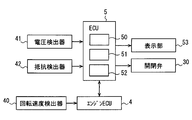
- thermoelectric generator of 1st Embodiment a control block diagram about the thermoelectric generator of 1st Embodiment
- it is a flowchart for executing data accumulation processing during engine operation
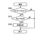
- it is a flowchart for executing a failure determination process at the time of engine restart
- It is a graph showing the open circuit voltage for each engine speed, stored in the storage unit for failure determination processing
- 2nd Embodiment it is a flowchart which performs a failure determination process at the time of engine restart
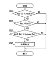
- 3rd Embodiment it is a flowchart which performs a failure determination process at the time of engine restart.
- thermoelectric generator 1 is a device that converts thermal energy into electric energy by the Seebeck effect using a temperature difference between the exhaust gas as the second fluid discharged from the engine 20 and the first fluid that is lower in temperature than the exhaust gas. is there.
- the thermoelectric generator 1 generates a potential difference when a temperature difference is given between the low temperature side portion 10a that is the first side portion and the high temperature side portion 10b that is the second side portion in the thermoelectric generator 10 having the thermoelectric conversion element. Electricity is generated using the phenomenon of electrons flowing. Any fluid capable of giving a temperature difference from the exhaust gas can be adopted as the first fluid. In this embodiment, a case where cooling water of an automobile engine 20 is used as an example of an arbitrarily selectable low-temperature fluid will be described.
- An engine 20 which is an internal combustion engine is connected to an intake pipe for sucking combustion air and an exhaust pipe 3 for discharging exhaust gas after combustion.
- a throttle valve whose opening is variable according to the amount of depression of an accelerator pedal provided in the vehicle is provided in the intake pipe.
- the engine 20 is controlled to an optimum operation by the engine control device 4.
- the engine control device 4 receives an engine speed signal, a throttle valve opening signal, a vehicle speed signal, and the like.
- the engine control device 4 stores in advance a control map in which the fuel injection amount is associated with the engine speed signal and the throttle valve opening signal.
- the engine control device 4 controls the fuel injection amount required at a predetermined timing on the intake pipe side based on the control map.
- the engine control device 4 is connected to the control device 5 of the thermoelectric generator 1 so as to be able to communicate with each other to exchange signals.
- the cooling water circuit 2 is connected to the engine 20.
- the cooling water circuit 2 is a circuit through which cooling water in the engine 20 circulates to cool the engine 20. Cooling water passes through the radiator 21 from the outlet 20b through the water pump 24 and circulates through the inlet 20a.
- the water pump 24 is, for example, an engine-driven pump that operates by receiving the driving force of the engine 20. Since the cooling water circulating through the cooling water circuit 2 is cooled by the heat radiation of the radiator 21, the operating temperature of the engine 20 can be controlled appropriately.
- the cooling water circuit 2 is provided with a bypass passage 26 that bypasses the radiator 21 and a thermostat 22 that adjusts the flow rate of the cooling water to the radiator 21 side or the bypass passage 26 side.
- a bypass passage 26 that bypasses the radiator 21
- a thermostat 22 that adjusts the flow rate of the cooling water to the radiator 21 side or the bypass passage 26 side.
- the cooling water circuit 2 is provided with a heater core 23 and a heater hot water circuit 25 forming a part of the cooling water circuit 2 so as to be in parallel with the radiator 21.
- the heater core 23 is a heat exchanger for a heating device that heats air for air conditioning using cooling water as a heat source.
- the thermoelectric generator 1 includes a thermoelectric generator 10 and a control device 5 that controls the operation of the thermoelectric generator 10.
- the thermoelectric generator 10 has a configuration in which a branch passage 31 that is a second fluid passage and a circulation passage 27 that is a first fluid passage are disposed with respect to a thermoelectric conversion element that generates power using the Seebeck effect.
- the branch passage 31 constitutes a passage formed so as to branch from the exhaust pipe 3 of the engine 20 and merge with the exhaust pipe 3 again, and is configured such that a part of the exhaust gas is diverted.
- the branch passage 31 comes into contact with the thermoelectric conversion element or the high temperature side portion 10b which is the second side surface of the thermoelectric generator 10, and the exhaust gas becomes a high temperature side heat source of the thermoelectric conversion element.
- An on-off valve 30 for opening and closing the branch passage 31 is provided on the upstream side of the exhaust gas with respect to the thermoelectric conversion element of the branch passage 31.
- the circulation passage 27 is a passage closer to the engine 20 than the bypass passage 26, and is a passage connecting the thermostat 22 and the inlet portion 20 a on the downstream side of the radiator 21.
- the circulation passage 27 is in contact with the thermoelectric conversion element or the low temperature side portion 10 a that is the first side surface of the thermoelectric generator 10.
- the cooling water flowing through the thermostat 22 from the bypass passage 26 or the cooling water passing through the radiator 21 and flowing through the thermostat 22 is supplied to the thermoelectric conversion element side, and this cooling water becomes a low temperature side heat source of the thermoelectric conversion element.
- the control device 5 includes a device such as a microcomputer that operates according to a program as a main hardware element. As illustrated in FIG. 2, the control device 5 includes an interface unit 50 (hereinafter also referred to as an I / F unit 50) to which various devices and various sensors are connected, an arithmetic processing unit 51, a storage unit 52, Is provided.
- the arithmetic processing unit 51 performs determination processing and arithmetic processing according to a predetermined program using information acquired from various sensors and various measuring devices through the I / F unit 50 and various data stored in the storage unit 52.
- the storage unit 52 includes a writable storage medium, and temporarily stores information based on signals output from the detectors in the storage medium.
- the storage unit 52 is a non-transitional tangible storage medium.
- the arithmetic processing unit 51 is a determination unit in the control device 5.
- the I / F unit 50 operates various devices based on the determination result and the calculation result by the calculation processing unit 51. Therefore, the I / F unit 50 is an input unit and a control output unit in the control device 5. Further, the control device 5 may be integrated with the engine control device 4 and constitute a part of the engine control device 4.
- the I / F unit 50 acquires engine speed, engine load information, and the like from the engine control device 4 as engine information signals.
- the engine load information is a torque value of the engine 20, for example.
- the rotation speed detector 40 is a sensor that detects the rotation speed of the engine 20.
- the arithmetic processing unit 51 performs arithmetic processing on various engine information signals from the engine control device 4 according to a preset program.
- the control device 5 controls the on-off valve 30 and the like based on the calculation result by the calculation processing unit 51.
- the control device 5 stores in advance a shaft torque map, a cooling loss heat amount map of the engine 20, a water flow rate map of the engine 20, a reference heat release amount map of the radiator 21, an opening degree map of the on-off valve 30, and various arithmetic expressions. .
- the control device 5 controls the opening degree of the on-off valve 30 based on these maps and arithmetic expressions.
- the arithmetic processing unit 51 performs arithmetic processing related to the failure determination of the thermoelectric generator 10 according to various information detected by the rotation speed detector 40, the voltage detector 41, the resistance detector 42, and the like and a predetermined program.
- the voltage detector 41 detects an open voltage in the thermoelectric generator 10 and outputs it to the control device 5.
- the open circuit voltage is also referred to as an open electromotive voltage.
- the open circuit voltage is data indicating the heat exchange performance of the thermoelectric generator 10, and cannot be accurately detected when the temperature difference between the low temperature side portion 10a and the high temperature side portion 10b is small.
- the control device 5 is configured to acquire data from the voltage detector 41 in accordance with the temperature difference between the low temperature side portion 10a and the high temperature side portion 10b. For example, the control device 5 acquires data from the voltage detector 41 when the temperature difference between the low temperature side portion 10a and the high temperature side portion 10b is large.
- the resistance detector 42 detects the AC resistance of the thermoelectric generator 10 and outputs it to the control device 5.
- the AC resistance is data indicating the electric resistance of the thermoelectric generator 10, and cannot be accurately detected when the temperature difference between the low temperature side portion 10a and the high temperature side portion 10b is large.
- the control device 5 is configured to acquire data from the resistance detector 42 when the temperature difference between the low temperature side portion 10a and the high temperature side portion 10b is small.
- the I / F unit 50 operates devices such as the on-off valve 30 based on the calculation result by the calculation processing unit 51.
- the I / F unit 50 is connected to a terminal device serving as a user interface, such as a control panel and a portable terminal.
- the user can check the current driving state output from the I / F unit 50 through the display screen 53 of the control panel, the display screen of the terminal device, or the like.
- the failure information of the thermoelectric generator 10 based on the failure determination process is displayed on the display screen of the display unit 53 or the like.
- This failure determination process is a process for determining whether or not a failure has occurred so that the thermoelectric generator 10 cannot generate electricity normally when the engine 20 is restarted.
- the flowchart shown in FIG. 3 shows processing executed by the control device 5 during operation of the engine 20.
- a process of storing the open circuit voltage Voc detected for each engine rotation speed as a performance value is performed.
- the flowchart shown in FIG. 4 shows processing executed by the control device 5 when restarting after the engine 20 is stopped.
- the arithmetic processing unit 51 determines whether or not the engine 20 is operating in S ⁇ b> 100. S100 is repeated until the engine 20 is operated.
- the maximum value Vocmax (Ne) of the open circuit voltage is set to zero and stored in the storage unit 52 in S110. Ne indicates the engine rotation speed when the open circuit voltage is detected.
- the control device 5 detects the open circuit voltage Voc by the voltage detector 41 during engine operation, and acquires the open circuit voltage Voc and the engine rotation speed as a set in association with the engine rotation speed at that time.
- Voc (Ne) acquired in S120 is larger than Vocmax (Ne) stored in the storage unit 52. Since Voc (Ne) acquired first after the operation of the engine 20 is greater than zero, the arithmetic processing unit 51 determines YES in S130, and sets the Voc (Ne) to Vocmax (Ne) in S140. Execute. The storage unit 52 stores new Vocmax (Ne). Next, in S150, it is determined whether or not the ignition switch is in an off state.
- the process returns to S120, and the control device 5 acquires the detected open-circuit voltage Voc as a set in association with the engine rotation speed.
- the process returns to S120 to detect Voc and detect the rotation speed and Voc. And get as a set.
- it determines with YES by S130, it acquires new Voc (Ne) during engine operation in S120, without rewriting acquired Voc (Ne) to Vocmax (Ne) by S140.
- the actual value of Voc is memorize
- each process of S200 and S220 is executed immediately before restarting the engine 20, that is, before the next operation of the engine 20 starts after the engine 20 is stopped. This is because the AC resistance of the thermoelectric generator 10 cannot be accurately detected when the thermoelectric generator 10 is heated by the exhaust gas and the temperature difference between the low temperature side portion 10a and the high temperature side portion 10b becomes large.
- the control device 5 can increase the accuracy of the failure determination by using the AC resistance value that is not affected by the temperature for the failure determination.
- the arithmetic processing unit 51 determines whether or not the open circuit voltage Voc (0) acquired before starting is smaller than a predetermined reference value Vocmin.
- Voc (0) immediately before starting the engine is a value equal to or higher than the reference value
- the thermoelectric conversion element is in a warm state, and a temperature difference between the low temperature side portion 10a and the high temperature side portion 10b of the thermoelectric conversion element is generated. Therefore, an abnormal AC resistance value cannot be accurately detected, and an accurate failure determination cannot be made.
- the reference value Vocmin is set to a value that can detect a state that can be determined except for such a state, and is stored in the control device 5 in advance. If NO is determined in S200, since the thermoelectric conversion element is warm and the failure cannot be determined, this flowchart is terminated without determining whether or not a failure has occurred.
- the arithmetic processing unit 51 determines whether or not the acquired AC resistance Rac detected by the resistance detector 42 is greater than a predetermined determination value Rac0 before starting.
- the determination value Rac0 is a value set in order to maintain that the power generation capacity required for the thermoelectric generator 10 as a product can be output.
- the determination value Rac0 is a value that is set on the basis of the fact that when Rac exceeds this value, it is in a state where the necessary power generation capacity cannot be exhibited. If it is determined NO in S210, it can be determined that the thermoelectric generator 10 is in a state capable of outputting the necessary power generation capability and is normal, and this flowchart is terminated.
- Vocmax (Ne) is the maximum value of Voc stored in the storage unit 52 for each actual rotational speed.
- Vocmax (Ne) is the largest Voc value in each column among the data arranged in a row in the vertical direction in the graph of FIG. In the graph of FIG. 5, a plurality of pieces of data arranged in a line in the vertical direction are actual values of the open-circuit voltage Voc detected at the same level of rotation speed.
- Voc0 in the determination process of S220 is larger than Vocmax (Ne) for all the rotation speeds shown in FIG. 5, it is determined as YES, and otherwise it is determined as NO.
- Vocmax Vocmax
- the control device 5 performs a process of notifying the user by displaying on the display unit 53 that the failure has occurred or notifying by voice or the like.
- a value obtained by dividing the estimated value Pteg of the power generation capacity by the target value Pteg0 of the power generation capacity is smaller than a predetermined determination value Ptegf.
- the determination value Ptegf is set to a value corresponding to, for example, a case where the power generation performance of the thermoelectric generator 10 has fallen beyond an allowable level from a 100% capacity state.
- Pteg / Pteg0 (Vocmax / Voc0) 2 / (Rac / Rac0) Further, Pteg is expressed by Voc 2 / Rac, and Pteg0 is expressed by Voc0 2 / Rac0.
- the thermoelectric generator 1 can acquire the circulation passage 27 through which the cooling water flows, the branch passage 31 through which the exhaust gas discharged from the engine 20 flows, the thermoelectric generator 10, and the open-circuit voltage and AC resistance of the thermoelectric generator 10.
- the control device 5 is provided.
- the thermoelectric generator 10 has a thermoelectric conversion element, is provided so that the heat of the cooling water can move to the low temperature side portion 10a, and the heat of the exhaust gas can move to the high temperature side portion 10b. Power is generated by the temperature difference between 10a and the high temperature side portion 10b.
- the control device 5 determines whether or not a failure has occurred in the thermoelectric generator 10 according to the detected AC resistance when the detected open-circuit voltage falls below the reference value immediately before the engine 20 is stopped and restarted. .
- thermoelectric generator 1 when the open circuit voltage detected immediately before starting again after the engine 20 is stopped is below the reference value, the thermoelectric generator 10 is not warmed. This state can be determined that there is not much temperature difference between the low temperature side portion 10a and the high temperature side portion 10b, and the AC resistance of the thermoelectric generator 10 can be accurately detected. This utilizes the property that when the temperature difference is large and the current value of the thermoelectric generator 10 is large, the error of the AC resistance, which is an electrical resistance, becomes large.
- the thermoelectric generator 1 determines whether or not a failure has occurred in the thermoelectric generator 10 according to the AC resistance detected in such a situation. For this reason, failure determination of the thermoelectric generator 10 can be carried out excluding parameters with high temperature dependence that can fluctuate complicatedly depending on the load. According to the thermoelectric generator 1, the accuracy of failure determination can be sufficiently improved compared to the conventional technology for performing failure determination using an estimated value of power generation based on the vehicle speed.
- the controller 5 detects that the detected open voltage is lower than the reference value, the detected AC resistance is higher than the determination value, and the open voltage detected after the engine 20 is restarted is the actual result of the open voltage. If it exceeds the value, make a decision regarding the power generation capacity.
- the control device 5 determines that a failure has occurred when the estimated value of the power generation capacity obtained using the detected AC resistance and the actual value of the open circuit voltage is lower than the allowable level.
- the estimated power generation capacity is further allowed. It is possible to provide a failure determination in which a determination is made as to whether or not the level is secured. Therefore, the accuracy of failure determination can be remarkably improved compared to the conventional technology for performing failure determination using the estimated value of the power generation amount based on the vehicle speed.
- the failure determination process at the time of engine restart of the second embodiment is that the failure occurrence process of S240 is executed when both S200 and S210 are determined to be YES with respect to the failure determination process of the first embodiment. Is different. According to the failure determination process of the second embodiment, an accurate AC resistance can be detected in a situation where there is not much temperature difference between the low temperature side portion 10a and the high temperature side portion 10b. The failure determination of the device 10 can be performed. According to this failure determination process, it is possible to sufficiently improve the accuracy of failure determination over the conventional technology that performs failure determination using the estimated value of the power generation amount based on the vehicle speed.
- the failure determination processing at the time of engine restart according to the third embodiment executes the failure occurrence processing at S240 when S200, S210, and S220 are all determined to be YES with respect to the failure determination processing according to the first embodiment.
- the point is different.
- failure determination is performed by detecting an accurate AC resistance in a situation where there is not much temperature difference between the low temperature side portion 10a and the high temperature side portion 10b and excluding a parameter having high temperature dependency. Can be implemented.
- the heat exchange performance after restart is compared with the past heat exchange performance.
- the accuracy of failure determination can be sufficiently improved as compared with the conventional technology that performs failure determination using the estimated value of the power generation amount based on the vehicle speed.
- the value of Rac0 used for the determination process in S210 may be configured as a determination value that is appropriately rewritten in the control device 5 in consideration of the aging deterioration of the thermoelectric conversion element.
- thermoelectric generator 10 is not configured to be covered with a case, and a large number of P-type semiconductor elements and N-type semiconductor elements are divided into a pipe that forms the branch passage 31 and a pipe that forms the circulation passage 27.
- produces on both sides may be sufficient.
- the case is not an essential component.
- the first fluid and the second fluid may form counterflows that flow in opposite directions.
Landscapes
- Engineering & Computer Science (AREA)
- Chemical & Material Sciences (AREA)
- Combustion & Propulsion (AREA)
- Mechanical Engineering (AREA)
- General Engineering & Computer Science (AREA)
- Control Of Eletrric Generators (AREA)
- Control Of Vehicle Engines Or Engines For Specific Uses (AREA)
Abstract
熱電発電装置は、第1流体が流れる第1流体通路(27)と、第1流体よりも高温であり、エンジン(20)から排出される第2流体が流れる第2流体通路(31)と、熱電変換素子を有し、第1側部(10a)に第1流体の熱が移動可能であり、第2側部(10b)に第2流体の熱が移動可能となるように設けられて、第1側部と第2側部との温度差によって発電する熱電発電器(10)と、熱電発電器についての開放電圧と交流抵抗とを取得可能な制御装置(5)と、を備える。制御装置は、エンジンが停止してから再始動する直前に、検出した開放電圧が基準値を下回る場合に、検出した交流抵抗に応じて熱電発電器の故障発生か否かを判定する。
Description
本出願は、2016年6月21日に出願された日本特許出願番号2016-122770号に基づくもので、ここにその記載内容を援用する。
この明細書における開示は、ゼーベック効果により熱エネルギを電力エネルギに変換する熱電発電装置に関する。
特許文献1の熱電発電装置は、車速センサが検出した車速の検出値と予め定めたマップから熱電変換器の発電量を推定し、熱電変換器の実発電量が推定発電量より小さい場合は熱電変換器が故障していると判定する。
車両において、排ガス温度、排ガス流量、冷却水温度、冷却水流量等は、車速に基づいて一義的に定まるものでなく、例えば、加速、制動等に関わる走行負荷によっても大きく影響を受けるパラメータである。このため、特許文献1の装置のように、車速に基づいて推定した発電量の精度には改良の余地があり、この発電量の推定値を用いた故障判定もその精度の点で課題がある。
本開示の目的は、故障判定の精度向上が図れる熱電発電装置を提供することである。
本開示の一態様による熱電発電装置は、第1流体が流れる第1流体通路と、第1流体よりも高温であり、エンジンから排出される第2流体が流れる第2流体通路と、熱電変換素子を有し、第1側部に第1流体の熱が移動可能であり、第2側部に第2流体の熱が移動可能となるように設けられて、第1側部と第2側部との温度差によって発電する熱電発電器と、熱電発電器についての開放電圧と交流抵抗とを取得可能な制御装置と、を備える。制御装置は、エンジンが停止してから再始動する直前に、検出した開放電圧が基準値を下回る場合に、検出した交流抵抗に応じて熱電発電器の故障発生か否かを判定する。
この熱電発電装置によれば、エンジンが停止後、再度始動する直前に検出した開放電圧が基準値を下回っている場合は熱電発電器が温まっていない。このとき、第1側部と第2側部との温度差があまりない状況であると判断でき、熱電発電器の交流抵抗を正確に検出することができる。これは、温度差が大きく、熱電発電器の電流値が大きい場合には電気的抵抗である交流抵抗の誤差が大きくなるからである。熱電発電装置は、このような状況において検出した交流抵抗に応じて熱電発電器の故障発生か否かを判定するため、負荷に応じて複雑に変動しうる温度依存性が高いパラメータを除いた故障判断を実施することができる。したがって、この熱電発電装置によれば、車速に基づいた発電量の推定値を用いて故障判定を行う従来技術に対して、故障判定の精度を向上することができる。
本開示についての上記目的およびその他の目的、特徴や利点は、添付の図面を参照しながら下記の詳細な記述により、より明確になる。その図面は、
第1実施形態の熱電発電装置と冷却水および排ガスとの関係を示した概要図であり、
第1実施形態の熱電発電装置に関する制御構成図であり、
第1実施形態において、エンジン運転中にデータ蓄積処理を実行するフローチャートであり、
第1実施形態において、エンジン再始動時に故障判定処理を実行するフローチャートであり、
故障判定処理のために記憶部に記憶される、エンジン回転速度毎の開放電圧を示すグラフであり、
第2実施形態において、エンジン再始動時に故障判定処理を実行するフローチャートであり、
第3実施形態において、エンジン再始動時に故障判定処理を実行するフローチャートである。
以下に、図面を参照しながら本開示を実施するための複数の形態を説明する。各形態において先行する形態で説明した事項に対応する部分には同一の参照符号を付して重複する説明を省略する場合がある。各形態において構成の一部のみを説明している場合は、構成の他の部分については先行して説明した他の形態を適用することができる。各実施形態で具体的に組み合わせが可能であることを明示している部分同士の組み合わせばかりではなく、特に組み合わせに支障が生じなければ、明示していなくても実施形態同士を部分的に組み合せることも可能である。
(第1実施形態)
第1実施形態の熱電発電装置1について、図1~図5を参照して説明する。熱電発電装置1は、エンジン20から排出される第2流体としての排ガスと排ガスよりも低温である第1流体との温度差を利用して、ゼーベック効果により熱エネルギを電力エネルギに変換する装置である。熱電発電装置1は、熱電変換素子を有する熱電発電器10において第1側部である低温側部10aと第2側部である高温側部10bとに温度差が与えられると、電位差が生じて電子が流れる現象を利用して発電する。第1流体には排ガスと温度差を与えることが可能な任意の流体を採用することができる。この実施形態では、任意に選択可能な低温流体の一例として、自動車のエンジン20の冷却水を用いる場合について説明する。
第1実施形態の熱電発電装置1について、図1~図5を参照して説明する。熱電発電装置1は、エンジン20から排出される第2流体としての排ガスと排ガスよりも低温である第1流体との温度差を利用して、ゼーベック効果により熱エネルギを電力エネルギに変換する装置である。熱電発電装置1は、熱電変換素子を有する熱電発電器10において第1側部である低温側部10aと第2側部である高温側部10bとに温度差が与えられると、電位差が生じて電子が流れる現象を利用して発電する。第1流体には排ガスと温度差を与えることが可能な任意の流体を採用することができる。この実施形態では、任意に選択可能な低温流体の一例として、自動車のエンジン20の冷却水を用いる場合について説明する。
内燃機関であるエンジン20には燃焼用の空気を吸入する吸気管と、燃焼後の排ガスを排出する排気管3が接続されている。吸気管内には、車両に設けられたアクセルペダルの踏み込み量に応じて開度が可変されるスロットルバルブが設けられている。エンジン20は、エンジン制御装置4によって最適な作動に制御される。エンジン制御装置4には、エンジン回転数信号、スロットルバルブ開度信号、および車速信号等が入力される。エンジン制御装置4は、エンジン回転数信号およびスロットルバルブ開度信号に対する燃料噴射量を対応付けた制御マップを予め記憶している。エンジン制御装置4は、制御マップに基づいて吸気管側に所定のタイミングで必要とされる燃料噴射量を制御する。エンジン制御装置4は、熱電発電装置1の制御装置5と互いの信号の授受が通信可能となるように接続されている。
エンジン20には冷却水回路2が接続されている。冷却水回路2は、エンジン20を冷却するためエンジン20内の冷却水が循環する回路である。冷却水は、ウォータポンプ24によって出口部20bからラジエータ21を通過して入口部20aに流通して循環する。ウォータポンプ24は、例えば、エンジン20の駆動力を受けて作動するエンジン駆動式のポンプである。冷却水回路2を循環する冷却水は、ラジエータ21の放熱によって冷却されるので、エンジン20の作動温度を適切に制御することができる。
冷却水回路2には、ラジエータ21をバイパスするバイパス通路26と、ラジエータ21側あるいはバイパス通路26側への冷却水流量を調節するサーモスタット22とが設けられている。冷却水温度が第1所定温度以下においては、サーモスタット22によってラジエータ21側が閉じられ、冷却水がバイパス通路26側を流通することで冷却水の過冷却を防止できる。これは、例えばエンジン20の始動直後のように冷却水が充分に昇温していない場合に対応し、エンジン20の暖機を促進することができる。さらにサーモスタット22は、エンジン20の暖機が終了して冷却水温度が第1所定温度を超えると、ラジエータ21側を開き始め、第2所定温度以上でバイパス通路26側を閉じ、ラジエータ21側を全開にする。冷却水回路2には、ラジエータ21に対して並列となるようにヒータコア23と、冷却水回路2の一部を成すヒータ温水回路25と、が設けられている。ヒータコア23は、冷却水を熱源として空調用空気を加熱する暖房装置用の熱交換器である。
熱電発電装置1は、熱電発電器10と、熱電発電器10の作動を制御する制御装置5と、を備えている。熱電発電器10は、ゼーベック効果を利用して発電を行う熱電変換素子に対して、第2流体通路である分岐通路31と、第1流体通路である循環通路27と、が配設されて構成されている。分岐通路31は、エンジン20の排気管3から分岐して再び排気管3に合流するように形成された通路を構成し、排ガスの一部が分流するように構成されている。分岐通路31は、熱電変換素子、あるいは熱電発電器10の第2側面である高温側部10bに接触し、排ガスが熱電変換素子の高温側熱源となる。分岐通路31の熱電変換素子に対する排ガスの上流側には、分岐通路31を開閉する開閉弁30が設けられている。
循環通路27は、バイパス通路26よりもエンジン20側となる通路であり、ラジエータ21の下流側で、サーモスタット22と入口部20aとを繋ぐ通路である。循環通路27は、熱電変換素子、あるいは熱電発電器10の第1側面である低温側部10aに接触している。バイパス通路26からサーモスタット22を流れる冷却水、あるいは、ラジエータ21を通過しサーモスタット22を流れる冷却水は、熱電変換素子側に供給され、この冷却水が熱電変換素子の低温側熱源となる。
制御装置5は、プログラムに従って動作するマイクロコンピュータのようなデバイスを主なハードウェア要素として備える。制御装置5は、図2に図示するように、各種装置と各種センサとが接続されるインターフェース部50(以下、I/F部50ともいう)と、演算処理部51と、記憶部52と、を備える。演算処理部51は、I/F部50を通して各種センサ、各種測定装置から取得した情報と、記憶部52に格納した各種データとを用いて所定のプログラムにしたがった判定処理や演算処理を行う。
記憶部52は、書き込み可能な記憶媒体を備えており、その記憶媒体に、各検出器から出力された信号に基づく情報を一時的に記憶する。記憶部52は、非遷移的実体的記録媒体(non-transitory tangible storage media)である。演算処理部51は、制御装置5における判定部である。I/F部50は、演算処理部51による判定結果、演算結果に基づいて各種装置を操作する。したがって、I/F部50は制御装置5における入力部および制御出力部である。また、制御装置5は、エンジン制御装置4と一体化され、エンジン制御装置4の一部を構成するものでもよい。
I/F部50は、エンジン情報信号としてエンジン回転数、エンジン負荷情報等をエンジン制御装置4から取得する。エンジン負荷情報とは、例えばエンジン20のトルク値である。回転速度検出器40は、エンジン20の回転速度を検出するセンサである。演算処理部51は、予め設定されたプログラムにしたがって、エンジン制御装置4からの各種のエンジン情報信号等に対する演算処理を行う。制御装置5は演算処理部51による演算結果に基づいて開閉弁30等の制御を行う。制御装置5は、軸トルクマップ、エンジン20の冷却損失熱量マップ、エンジン20の通水流量マップ、ラジエータ21の基準放熱量マップ、開閉弁30の開度マップや各種演算式を予め記憶している。制御装置5は、これらのマップや演算式に基づいて開閉弁30の開度を制御する。
演算処理部51は、回転速度検出器40、電圧検出器41、抵抗検出器42等によって検出される各種情報と所定のプログラムとにしたがって、熱電発電器10の故障判断に係る演算処理を行う。電圧検出器41は、熱電発電器10における開放電圧を検出し、制御装置5に出力する。開放電圧は、開放起電圧とも称する。開放電圧は、熱電発電器10の熱交換性能を示すデータであり、低温側部10aと高温側部10bとの温度差が小さいときは正確に検出できないデータである。制御装置5は、低温側部10aと高温側部10bとの温度差に応じて電圧検出器41からデータ取得するように構成されている。例えば、制御装置5は、低温側部10aと高温側部10bとの温度差が大きい場合に電圧検出器41からデータ取得する。
抵抗検出器42は、熱電発電器10についての交流抵抗を検出し、制御装置5に出力する。交流抵抗は、熱電発電器10の電気抵抗を示すデータであり、低温側部10aと高温側部10bとの温度差が大きいときは正確に検出できないデータである。制御装置5は、低温側部10aと高温側部10bとの温度差が小さいときに抵抗検出器42からデータ取得するように構成されている。
I/F部50は、演算処理部51による演算結果に基づいて開閉弁30等の機器を操作する。I/F部50には、ユーザインターフェイスとなる端末装置、例えば、コントロールパネル、携帯用端末機等が接続される。使用者は、コントロールパネルの表示部53、端末装置等の表示画面を通じて、I/F部50から出力された現在の運転状態を確認することができる。また、表示部53等の表示画面には、故障判定処理に基づいた熱電発電器10の故障情報が表示される。
次に、熱電発電装置1が実行する故障判定処理の一例について図3~図5を参照して説明する。この故障判定処理は、熱電発電器10が正常に発電できないような故障が発生しているか否かをエンジン20の再始動の際に判定する処理である。図3に示すフローチャートは、エンジン20の運転中に制御装置5によって実行される処理を示している。図3に示すフローチャートでは、エンジン20の運転中に、エンジン回転速度毎に検出した開放電圧Vocを実績値として記憶する処理が行われる。図4に示すフローチャートは、エンジン20の停止後、再始動を行う際に制御装置5によって実行される処理を示している。
図3に示すように、判定部である演算処理部51は、S100でエンジン20が作動しているか否かを判定する。S100はエンジン20が作動されるまで繰り返され、運転中になると、S110で開放電圧の最大値Vocmax(Ne)をゼロに設定して記憶部52に記憶させる処理を実行する。Neは開放電圧検出時のエンジン回転速度を示している。S120で制御装置5は、エンジン運転中に電圧検出器41によって開放電圧Vocを検出し、そのときのエンジン回転速度に対応付けて開放電圧Vocとエンジン回転速度とをセットで取得する。
S130では、S120で取得したVoc(Ne)が、記憶部52に記憶されているVocmax(Ne)よりも大きいか否かを判定する。エンジン20の運転後、最初に取得したVoc(Ne)はゼロよりも大きいので、S130で演算処理部51はYESと判定し、S140でこのVoc(Ne)をVocmax(Ne)に設定する処理を実行する。記憶部52には、新たなVocmax(Ne)が記憶されることになる。次にS150でイグニッションスイッチがオフ状態か否かを判定し、オフ状態であれば本フローチャートを終了する。
イグニッションスイッチがオフ状態ではなく、エンジン20が運転継続中である場合は、S120に戻り、制御装置5は、検出された開放電圧Vocをエンジン回転速度に対応付けてセットで取得する。S130において、S120で取得したVoc(Ne)が、記憶部52に記憶されている同等レベルの回転速度のVocmax(Ne)以下と判定した場合は、S120に戻ってVocを検出し回転速度とVocとをセットで取得する。このようにS130でYESと判定するまで、取得したVoc(Ne)をS140でVocmax(Ne)に書き換えることなく、S120でエンジン運転中の新しいVoc(Ne)を取得し続ける。S130において、S120で取得したVoc(Ne)が、同等レベルのエンジン回転速度におけるVocmax(Ne)より大きいと判定した場合は、S140でVocmax(Ne)を更新し、記憶部52に記憶させる処理を実行する。
Vocの実績値は、例えば図5に図示するグラフのように、同じエンジン回転速度毎の開放電圧値として記憶部52に記憶されている。Vocの実績値は、同じエンジン目標回転速度毎の開放電圧値として、または同じ車速毎の開放電圧値として記憶部52に記憶されているように構成してもよい。
イグニッションスイッチがオフ状態になると、図3のS150でYESと判定して図3のフローチャートを終了し、エンジン運転中における開放電圧Vocのデータ蓄積を終了する。次にエンジン20が再始動する際には、制御装置5は図4に係るフローチャートに示す処理を開始する。制御装置5は、エンジン20を再始動する信号をエンジン制御装置4から取得すると、図4のフローチャートにしたがった処理を実行する。
図4に示すように、エンジン20の再始動直前に、つまりエンジン20の停止後エンジン20の次回運転が始まる前に、S200、S220の各処理を実行する。これは、熱電発電器10が排ガスによって温められて低温側部10aと高温側部10bとの温度差が大きくなると、熱電発電器10の交流抵抗を正確に検出できないからである。制御装置5は、温度影響を受けていない状態の交流抵抗値を故障判定に用いることによって、故障判定の精度を高めることができる。
まずS200において、演算処理部51は、始動前に取得した開放電圧Voc(0)が所定の基準値であるVocminよりも小さいか否かを判定する。エンジン始動直前のVoc(0)が基準値以上の値であると、熱電変換素子が温まっている状態であり、熱電変換素子の低温側部10aと高温側部10bとの温度差が生じているため、異常な交流抵抗値を正確に検出できず、正確な故障判定ができない。基準値Vocminは、このような状態を除いて判定可能な状態を検出できるような値に設定されており、制御装置5に予め記憶されている。S200でNOと判定すると、熱電変換素子が温まっており故障判定不可能な状態であるので、故障発生の有無を判定せず本フローチャートを終了する。
S200でYESと判定すると、S210で演算処理部51は、始動前に抵抗検出器42によって検出されて、取得した交流抵抗Racが所定の判定値であるRac0よりも大きいか否かを判定する。判定値Rac0は、製品として熱電発電器10に要求されている発電能力を出力可能な状態であることを維持するために、設定される値である。例えば、判定値Rac0は、Racがこの値を超えると、必要な発電能力を発揮できない状態になっていることを基準として設定される値である。S210でNOと判定すると、熱電発電器10が必要な発電能力を出力可能な状態であり正常であると判定でき、本フローチャートを終了する。
S210でYESと判定すると、次にS220で演算処理部51は、エンジン20の始動後に検出したVoc0(Ne)が記憶部52に記憶されているVocmax(Ne)よりも大きいか否かを判定する。Vocmax(Ne)は、記憶部52に記憶されている、実回転速度毎のVocの最大値である。例えばVocmax(Ne)は、図5のグラフにおける縦方向に一列に複数並ぶデータのうち、各列において最も大きいVocの値である。図5のグラフにおいて縦方向に一列に複数並ぶデータは、同等レベルの回転速度について検出された開放電圧Vocの実績値である。したがって、S220の判定処理におけるVoc0は、図5に図示する、すべての回転速度についてのVocmax(Ne)よりも大きい場合にはYESと判定され、そうでない場合にはNOと判定される。このようにS220では、エンジン20の再始動の際に検出した開放電圧値が、記憶された開放電圧の実績値のうち、すべての実回転速度における開放電圧の最大値に対して上回っているか否かを判定する。
S220でNOと判定すると、この実施形態では正常であると判定して、本フローチャートを終了する。S220でYESと判定すると、演算処理部51はS230で、開放電圧の実績値から推定される発電能力の推定値が許容レベルよりも低下しているか否かを判定する。S230でNOと判定すると、熱電発電器10が故障しているとは判定しないで、本フローチャートを終了する。S230でYESと判定すると、熱電発電器10が所望の発電能力を発揮できない状態であるため、S240で故障発生の処理を実行し、本フローチャートを終了する。例えば、制御装置5は、故障発生である旨を表示部53に表示したり、音声等で報知したりしてユーザーに知らせる処理を行う。
S230では、発電能力の推定値Ptegを発電能力の狙い値Pteg0で割り算して得られる値が所定の判断値Ptegfより小さいか否かを判定する。判断値Ptegfは、例えば熱電発電器10の発電性能が100%の能力状態から許容レベルを超えて低下した場合に相当する値に設定される。
Pteg/Pteg0は次式によって算出するものする。
Pteg/Pteg0=(Vocmax/Voc0)2/(Rac/Rac0)
また、PtegはVoc2/Racで表され、Pteg0はVoc02/Rac0で表される。
また、PtegはVoc2/Racで表され、Pteg0はVoc02/Rac0で表される。
次に、第1実施形態の熱電発電装置1がもたらす作用効果について説明する。熱電発電装置1は、冷却水が流れる循環通路27と、エンジン20から排出される排ガスが流れる分岐通路31と、熱電発電器10と、熱電発電器10についての開放電圧と交流抵抗とを取得可能な制御装置5と、を備える。熱電発電器10は、熱電変換素子を有し、低温側部10aに冷却水の熱が移動可能であり、高温側部10bに排ガスの熱が移動可能となるように設けられて、低温側部10aと高温側部10bとの温度差によって発電する。制御装置5は、エンジン20が停止してから再始動する直前に、検出した開放電圧が基準値を下回る場合に、検出した交流抵抗に応じて熱電発電器10の故障発生か否かを判定する。
この熱電発電装置1によれば、エンジン20が停止後、再度始動する直前に検出した開放電圧が基準値を下回っている場合は熱電発電器10が温まっていない状態である。この状態は、低温側部10aと高温側部10bとの温度差があまりない状況であると判断でき、熱電発電器10の交流抵抗を正確に検出することができる。これは、温度差が大きく熱電発電器10の電流値が大きい場合には電気的抵抗である交流抵抗の誤差が大きくなる性質を利用している。熱電発電装置1は、このような状況において検出した交流抵抗に応じて熱電発電器10の故障発生か否かを判定する。このため、負荷に応じて複雑に変動しうる温度依存性が高いパラメータを除いた熱電発電器10の故障判断を実施できる。この熱電発電装置1によれば、従来の車速に基づいた発電量の推定値を用いて故障判定を行う技術に対して、故障判定の精度を十分に向上することができる。
制御装置5は、エンジン20が再始動する直前に、検出した開放電圧が基準値を下回り、検出した交流抵抗が判定値を上回り、さらにエンジン20の再始動後に検出した開放電圧が開放電圧の実績値を上回っている場合に、さらに発電能力に関わる判定を行う。制御装置5は、検出した交流抵抗と開放電圧の実績値とを用いて求めた発電能力の推定値が許容レベルよりも低下しているときに故障が発生していると判定する。
この故障判定によれば、温度依存性が高いパラメータを除いた判定処理と過去の熱交換性能に対して再始動後の熱交換性能を比較した判定処理とに加えて、さらに推定発電能力が許容レベルを確保している否かという判断を実施した故障判定を提供できる。したがって、従来の車速に基づいた発電量の推定値を用いて故障判定を行う技術に対して、故障判定の精度を格段に向上することができる。
(第2実施形態)
第2実施形態におけるエンジン再始動時の故障判定処理について図6のフローチャートを参照して説明する。図6において第1実施形態の図4と同じ符号を付したステップは、第1実施形態と同様である。第2実施形態で特に説明しない構成、処理、作用、効果については、第1実施形態と同様であり、以下、第1実施形態と異なる点についてのみ説明する。
第2実施形態におけるエンジン再始動時の故障判定処理について図6のフローチャートを参照して説明する。図6において第1実施形態の図4と同じ符号を付したステップは、第1実施形態と同様である。第2実施形態で特に説明しない構成、処理、作用、効果については、第1実施形態と同様であり、以下、第1実施形態と異なる点についてのみ説明する。
第2実施形態のエンジン再始動時の故障判定処理は、第1実施形態の故障判定処理に対して、S200、S210がともにYESと判定された場合にS240の故障発生の処理を実行する点が相違する。第2実施形態の故障判定処理によれば、低温側部10aと高温側部10bとの温度差があまりない状況において正確な交流抵抗を検出できるので、温度依存性が高いパラメータを除いた熱電発電器10の故障判断を実施できる。この故障判定処理によれば、従来の車速に基づいた発電量の推定値を用いて故障判定を行う技術に対して、故障判定の精度を十分に向上することができる。
(第3実施形態)
第3実施形態におけるエンジン再始動時の故障判定処理について図7のフローチャートを参照して説明する。図7において第1実施形態の図4と同じ符号を付したステップは、第1実施形態と同様である。第3実施形態で特に説明しない構成、処理、作用、効果については、第1実施形態と同様であり、以下、第1実施形態と異なる点についてのみ説明する。
第3実施形態におけるエンジン再始動時の故障判定処理について図7のフローチャートを参照して説明する。図7において第1実施形態の図4と同じ符号を付したステップは、第1実施形態と同様である。第3実施形態で特に説明しない構成、処理、作用、効果については、第1実施形態と同様であり、以下、第1実施形態と異なる点についてのみ説明する。
第3実施形態のエンジン再始動時の故障判定処理は、第1実施形態の故障判定処理に対して、S200、S210、S220がともにYESと判定された場合にS240の故障発生の処理を実行する点が相違する。第3実施形態の故障判定処理によれば、低温側部10aと高温側部10bとの温度差があまりない状況において正確な交流抵抗を検出して、温度依存性が高いパラメータを除いた故障判断を実施できる。さらに、エンジン20の再始動後に検出した開放電圧が開放電圧の実績値を上回っている場合に故障が発生していると判定するため、過去の熱交換性能に対して再始動後の熱交換性能を比較した故障判定を実施できる。第3実施形態の故障判定処理によれば、従来の車速に基づいた発電量の推定値を用いて故障判定を行う技術に対して、故障判定の精度を十分に向上することができる。
(他の実施形態)
この明細書の開示は、例示された実施形態に制限されない。開示は、例示された実施形態と、それらに基づく当業者による変形態様を包含する。例えば、開示は、実施形態において示された部品、要素の組み合わせに限定されず、種々変形して実施することが可能である。開示は、多様な組み合わせによって実施可能である。開示は、実施形態に追加可能な追加的な部分をもつことができる。開示は、実施形態の部品、要素が省略されたものを包含する。開示は、ひとつの実施形態と他の実施形態との間における部品、要素の置き換え、または組み合わせを包含する。開示される技術的範囲は、実施形態の記載に限定されない。開示される技術的範囲は、特許請求の範囲の記載によって示され、さらに特許請求の範囲の記載と均等の意味および範囲内でのすべての変更を含むものと解されるべきである。
この明細書の開示は、例示された実施形態に制限されない。開示は、例示された実施形態と、それらに基づく当業者による変形態様を包含する。例えば、開示は、実施形態において示された部品、要素の組み合わせに限定されず、種々変形して実施することが可能である。開示は、多様な組み合わせによって実施可能である。開示は、実施形態に追加可能な追加的な部分をもつことができる。開示は、実施形態の部品、要素が省略されたものを包含する。開示は、ひとつの実施形態と他の実施形態との間における部品、要素の置き換え、または組み合わせを包含する。開示される技術的範囲は、実施形態の記載に限定されない。開示される技術的範囲は、特許請求の範囲の記載によって示され、さらに特許請求の範囲の記載と均等の意味および範囲内でのすべての変更を含むものと解されるべきである。
前述の実施形態において、S210での判定処理に用いるRac0の値は、熱電変換素子の経年劣化等を考慮して、制御装置5において適宜書き換えられる判定値として構成してもよい。
前述の実施形態の熱電発電器10は、ケースによって覆われる構成ではなく、多数のP型半導体素子とN型半導体素子とが、分岐通路31を形成する配管と循環通路27を形成する配管とに接触し、両側部に温度差が発生する構成でもよい。熱電発電器10においてケースは必須の構成要素ではない。
前述の実施形態において、第1流体と第2流体は、互いに逆向きに流れる対向流を形成してもよい。
Claims (6)
- 第1流体が流れる第1流体通路(27)と、
前記第1流体よりも高温であり、エンジン(20)から排出される第2流体が流れる第2流体通路(31)と、
熱電変換素子を有し、第1側部(10a)に前記第1流体の熱が移動可能であり、第2側部(10b)に前記第2流体の熱が移動可能となるように設けられて、前記第1側部と前記第2側部との温度差によって発電する熱電発電器(10)と、
前記熱電発電器についての開放電圧と交流抵抗とを取得可能な制御装置(5)と、
を備え、
前記制御装置は、前記エンジンが停止してから再始動する直前に、検出した前記開放電圧が基準値を下回る場合に、検出した前記交流抵抗に応じて前記熱電発電器の故障発生か否かを判定する熱電発電装置。 - 前記制御装置は、前記エンジンの運転中に検出した前記開放電圧の実績値を記憶しており、
前記制御装置は、前記エンジンが前記再始動する直前に、検出した前記開放電圧が前記基準値を下回り、かつ検出した前記交流抵抗が判定値を上回る場合に、前記エンジンの再始動後に検出した前記開放電圧が前記開放電圧の実績値を上回っているときに故障が発生していると判定する請求項1に記載の熱電発電装置。 - 前記制御装置は、前記エンジンが前記再始動する直前に、検出した前記開放電圧が前記基準値を下回り、検出した前記交流抵抗が前記判定値を上回り、さらに前記エンジンの再始動後に検出した前記開放電圧が前記開放電圧の実績値を上回っている場合に、検出した前記交流抵抗と前記開放電圧の実績値とを用いて求めた発電能力の推定値が許容レベルよりも低下しているときに故障が発生していると判定する請求項2に記載の熱電発電装置。
- 前記制御装置は、前記エンジンの再始動の際に検出した前記開放電圧が、前記エンジンの実回転速度に対応付けて記憶された前記開放電圧の実績値のうち、すべての前記実回転速度における前記開放電圧の最大値に対して上回っている場合に、故障が発生していると判定する請求項2に記載の熱電発電装置。
- 前記制御装置は、前記エンジンの再始動の際に検出した前記開放電圧が、前記エンジンの目標回転速度に対応付けて記憶された前記開放電圧の実績値のうち、すべての前記目標回転速度における前記開放電圧の最大値に対して上回っている場合に、故障が発生していると判定する請求項2に記載の熱電発電装置。
- 前記制御装置は、前記エンジンの再始動の際に検出した前記開放電圧が、車速に対応付けて記憶された前記開放電圧の実績値のうち、すべての車速における前記開放電圧の最大値に対して上回っている場合に、故障が発生していると判定する請求項2に記載の熱電発電装置。
Applications Claiming Priority (2)
| Application Number | Priority Date | Filing Date | Title |
|---|---|---|---|
| JP2016-122770 | 2016-06-21 | ||
| JP2016122770A JP6547694B2 (ja) | 2016-06-21 | 2016-06-21 | 熱電発電装置 |
Publications (1)
| Publication Number | Publication Date |
|---|---|
| WO2017221565A1 true WO2017221565A1 (ja) | 2017-12-28 |
Family
ID=60783454
Family Applications (1)
| Application Number | Title | Priority Date | Filing Date |
|---|---|---|---|
| PCT/JP2017/017514 Ceased WO2017221565A1 (ja) | 2016-06-21 | 2017-05-09 | 熱電発電装置 |
Country Status (2)
| Country | Link |
|---|---|
| JP (1) | JP6547694B2 (ja) |
| WO (1) | WO2017221565A1 (ja) |
Citations (5)
| Publication number | Priority date | Publication date | Assignee | Title |
|---|---|---|---|---|
| JPH1132492A (ja) * | 1997-05-14 | 1999-02-02 | Nissan Motor Co Ltd | 熱電発電装置及びその駆動方法 |
| JP2007014084A (ja) * | 2005-06-29 | 2007-01-18 | Toyota Motor Corp | 熱電発電装置 |
| JP2010010637A (ja) * | 2008-06-29 | 2010-01-14 | Hiroshi Nagayoshi | 熱電発電装置 |
| JP2013099067A (ja) * | 2011-10-31 | 2013-05-20 | Daihatsu Motor Co Ltd | 車載発電システム |
| JP2013147974A (ja) * | 2012-01-18 | 2013-08-01 | Toyota Motor Corp | 熱電発電装置 |
-
2016
- 2016-06-21 JP JP2016122770A patent/JP6547694B2/ja not_active Expired - Fee Related
-
2017
- 2017-05-09 WO PCT/JP2017/017514 patent/WO2017221565A1/ja not_active Ceased
Patent Citations (5)
| Publication number | Priority date | Publication date | Assignee | Title |
|---|---|---|---|---|
| JPH1132492A (ja) * | 1997-05-14 | 1999-02-02 | Nissan Motor Co Ltd | 熱電発電装置及びその駆動方法 |
| JP2007014084A (ja) * | 2005-06-29 | 2007-01-18 | Toyota Motor Corp | 熱電発電装置 |
| JP2010010637A (ja) * | 2008-06-29 | 2010-01-14 | Hiroshi Nagayoshi | 熱電発電装置 |
| JP2013099067A (ja) * | 2011-10-31 | 2013-05-20 | Daihatsu Motor Co Ltd | 車載発電システム |
| JP2013147974A (ja) * | 2012-01-18 | 2013-08-01 | Toyota Motor Corp | 熱電発電装置 |
Also Published As
| Publication number | Publication date |
|---|---|
| JP2017229135A (ja) | 2017-12-28 |
| JP6547694B2 (ja) | 2019-07-24 |
Similar Documents
| Publication | Publication Date | Title |
|---|---|---|
| JP3932035B2 (ja) | 内燃機関の冷却系の異常診断装置 | |
| US9448194B2 (en) | Apparatus and method of determining failure in thermostat | |
| JP4876202B2 (ja) | 可変ウォータポンプの制御装置 | |
| US8479569B2 (en) | Malfunction determination apparatus for cooling apparatus and malfunction determination method for cooling apparatus | |
| CN109935867B (zh) | 用于诊断燃料电池的温度传感器故障的方法和系统 | |
| JP4883225B2 (ja) | 車両の冷却装置 | |
| JP4304782B2 (ja) | エンジン冷却系におけるサーモスタットの故障診断装置 | |
| US9631585B2 (en) | EGHR mechanism diagnostics | |
| JP5839021B2 (ja) | 内燃機関の冷却装置 | |
| US10067005B2 (en) | Apparatus for estimating temperatures of vehicle | |
| JP2015059458A (ja) | クーリングシステムの制御装置 | |
| JP4561529B2 (ja) | 内燃機関冷却装置の故障検出システム | |
| JP4385492B2 (ja) | サーモスタットの故障診断装置 | |
| JP6040908B2 (ja) | 車両 | |
| JP2013238234A (ja) | レンジエクステンダ付き内燃機関を冷却するための方法およびレンジエクステンダ付き内燃機関を冷却するための装置 | |
| JP2006336626A (ja) | 内燃機関の冷却装置の故障検出システム | |
| WO2017221565A1 (ja) | 熱電発電装置 | |
| US9822739B2 (en) | Vehicle with an EGR-cooler and its diagnotic | |
| JP5878052B2 (ja) | エンジンの制御装置 | |
| JP6028708B2 (ja) | 車両 | |
| CN114810300A (zh) | 用于对具有电加热器的催化器进行诊断的方法和装置 | |
| JP2009174387A (ja) | 内燃機関の冷却制御装置および冷却制御方法 | |
| JP2010265789A (ja) | エンジン制御装置 |
Legal Events
| Date | Code | Title | Description |
|---|---|---|---|
| 121 | Ep: the epo has been informed by wipo that ep was designated in this application |
Ref document number: 17815035 Country of ref document: EP Kind code of ref document: A1 |
|
| NENP | Non-entry into the national phase |
Ref country code: DE |
|
| 122 | Ep: pct application non-entry in european phase |
Ref document number: 17815035 Country of ref document: EP Kind code of ref document: A1 |