WO2017221471A1 - 異形断面ガラス繊維製造用ノズル並びに異形断面ガラス繊維製造装置及びその製造方法 - Google Patents
異形断面ガラス繊維製造用ノズル並びに異形断面ガラス繊維製造装置及びその製造方法 Download PDFInfo
- Publication number
- WO2017221471A1 WO2017221471A1 PCT/JP2017/009264 JP2017009264W WO2017221471A1 WO 2017221471 A1 WO2017221471 A1 WO 2017221471A1 JP 2017009264 W JP2017009264 W JP 2017009264W WO 2017221471 A1 WO2017221471 A1 WO 2017221471A1
- Authority
- WO
- WIPO (PCT)
- Prior art keywords
- nozzle
- glass fiber
- modified cross
- section
- shape
- Prior art date
- Legal status (The legal status is an assumption and is not a legal conclusion. Google has not performed a legal analysis and makes no representation as to the accuracy of the status listed.)
- Ceased
Links
Images





































Classifications
-
- C—CHEMISTRY; METALLURGY
- C03—GLASS; MINERAL OR SLAG WOOL
- C03B—MANUFACTURE, SHAPING, OR SUPPLEMENTARY PROCESSES
- C03B37/00—Manufacture or treatment of flakes, fibres, or filaments from softened glass, minerals, or slags
- C03B37/08—Bushings, e.g. construction, bushing reinforcement means; Spinnerettes; Nozzles; Nozzle plates
- C03B37/083—Nozzles; Bushing nozzle plates
-
- D—TEXTILES; PAPER
- D01—NATURAL OR MAN-MADE THREADS OR FIBRES; SPINNING
- D01D—MECHANICAL METHODS OR APPARATUS IN THE MANUFACTURE OF ARTIFICIAL FILAMENTS, THREADS, FIBRES, BRISTLES OR RIBBONS
- D01D5/00—Formation of filaments, threads, or the like
- D01D5/253—Formation of filaments, threads, or the like with a non-circular cross section; Spinnerette packs therefor
Definitions
- the present invention relates to an improvement in manufacturing technology for irregular cross-section glass fibers.
- a non-circular cross-section glass fiber with a non-circular cross section such as an oblong or elliptical cross section can be used in various fields because it can achieve a high reinforcing effect when mixed with a resin and compounded. Yes.
- This type of irregular cross-section glass fiber is generally manufactured by cooling while pulling out molten glass from a nozzle. At this time, since the shape of the nozzle hole at the tip of the nozzle forms the basis of the cross-sectional shape of the glass fiber to be manufactured, the nozzle hole may be flattened at the tip of the nozzle when manufacturing a modified cross-section glass fiber. Many.
- the notch portion disclosed in FIGS. 18 to 20 of Patent Document 1 has a rectangular shape in which the opening width on the base end side (the molten glass inflow side) and the opening width on the distal end side (the molten glass outflow side) are substantially the same. Shape. For this reason, the strength of the nozzle tip provided with the notch is inevitably weakened. In particular, in order to increase the opening area of the rectangular notch, when the rectangular notch is provided in substantially the entire long wall, the remaining portion of the nozzle tip excluding the notch is substantially Since only the pair of short wall portions facing each other on the long diameter side of the nozzle hole are provided, the strength reduction of the nozzle tip portion becomes more remarkable.
- an object of the present invention is to appropriately adjust the viscosity of molten glass at the time of molding while suppressing thermal deformation of the nozzle, and to stably mold deformed cross-section glass fibers.
- the nozzle for producing a modified cross-section glass fiber according to the present invention is a pair of flat nozzle holes and a pair of nozzle holes facing each other in the minor axis direction of the nozzle holes at the tip portion where the molten glass flows out.
- a nozzle for manufacturing a modified cross-section glass fiber comprising a first wall portion and a pair of second wall portions facing each other in the major axis direction of the nozzle hole, each of the pair of first wall portions having a tip It is characterized by having a concave notch part in which the opening width in the major axis direction gradually increases toward the side.
- the opening width of the cutout portion gradually increases as it goes toward the front end side, the proximal end area of the remaining portion of the first wall portion excluding the cutout portion at the nozzle front end portion. Becomes larger than the tip side area.
- the strength of the first wall portion on the base end side is sufficiently ensured, and the nozzle tip portion provided with the notch portion is hardly thermally deformed. Since the opening width of the notch portion on the tip side becomes large with the nozzle strength secured in this way, the opening area of the notch portion can be sufficiently secured. Therefore, the molten glass can be sufficiently cooled through the notches on both sides.
- the modified cross-section glass fiber is manufactured by the nozzle having the above-described configuration, it becomes possible to stably form the modified cross-section glass fiber having a non-circular cross section such as a flat shape.
- a modified cross-section glass fiber with little variation can be obtained.
- the cutout portion is formed only in the central portion in the major axis direction of the first wall portion. If it does in this way, a notch will not be formed in the both ends of the major axis direction of the 1st wall part. Therefore, it is easy to ensure the strength of the first wall portion on the tip side, and thermal deformation of the nozzle can be prevented more reliably.
- the cutout portion may be one shape selected from a triangular shape, a trapezoidal shape, and a bow shape formed of a string and an arc.
- a bow shape such as a trapezoidal shape or a semicircular shape is preferable because an acute angle portion is not formed in the notch portion.
- the modified cross-section glass fiber manufacturing apparatus which has been invented in order to solve the above-described problems, is characterized in that it includes a bushing in which a plurality of nozzles having the above-described configuration are provided at the bottom. According to such a configuration, it is possible to receive the same effect as the corresponding configuration already described.
- the cooling means is arranged so as to face the notch of the nozzle. If it does in this way, molten glass can be cooled more efficiently through a notch part.
- a plurality of nozzle rows in which a plurality of nozzles with the major axis direction oriented in the same direction are arranged on the same straight line extending in the major axis direction are arranged in parallel, and the cooling means is adjacent to the nozzle row. In between, it may be arrange
- the modified cross-section glass fiber manufacturing method according to the present invention which has been devised to solve the above problems, includes a flat nozzle hole, a pair of first wall portions opposed in the minor axis direction of the nozzle hole, and a nozzle hole
- the present invention is characterized in that it has a concave notch portion in which the opening width in the major axis direction gradually increases toward the tip side. According to such a configuration, it is possible to receive the same effect as the corresponding configuration already described.
- the molten glass may be E glass.
- E glass is a glass that is not easily devitrified, there is an advantage that the productivity of the modified cross-section glass fiber is improved.
- the molten glass preferably has a viscosity of 10 2.0 to 10 3.5 dPa ⁇ s at the molding temperature. That is, if it is 10 3.5 dPa ⁇ s or less, the viscosity of the molten glass does not become too high, and thus the glass fiber moldability can be maintained well. Further, if the viscosity is 10 2.0 dPa ⁇ s or more, the viscosity of the molten glass does not become too low, so the force that the molten glass tries to return to the circular cross section by the surface tension is weakened, and the flatness ratio of the glass fiber (major dimension / short (Diameter dimension) can be increased.
- FIG. 4B is a cross-sectional view taken along the line A1-A1 of FIG. 4A. It is B1-B1 sectional drawing of FIG. 4A. FIG. 4B is a sectional view taken along line C1-C1 in FIG. 4A. It is a side view which shows the nozzle which concerns on the 2nd Embodiment of this invention.
- FIG. 5A It is A2-A2 sectional drawing of FIG. 5A. It is B2-B2 sectional drawing of FIG. 5A. It is C2-C2 sectional drawing of FIG. 5A. It is a side view which shows the nozzle which concerns on the 3rd Embodiment of this invention. It is A3-A3 sectional drawing of FIG. 6A. It is B3-B3 sectional drawing of FIG. 6A. It is C3-C3 sectional drawing of FIG. 6A. It is a side view which shows the nozzle which concerns on the 4th Embodiment of this invention. It is A4-A4 sectional drawing of FIG. 7A. It is B4-B4 sectional drawing of FIG. 7A. It is C4-C4 sectional drawing of FIG. 7A.
- FIG. 9B is a sectional view taken along line A6-A6 of FIG. 9A.
- FIG. 9B is a sectional view taken along line B6-B6 of FIG. 9A.
- FIG. 9B is a sectional view taken along the line C6-C6 of FIG. 9A.
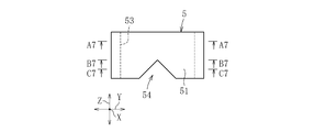
- FIG. 10B is a sectional view taken along line A7-A7 of FIG. 10A.
- FIG. 10B is a B7-B7 cross-sectional view of FIG. 10A.
- FIG. 10B is a sectional view taken along the line C7-C7 of FIG. 10A.
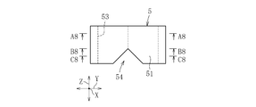
- FIG. 11B is a sectional view taken along the line A8-A8 of FIG. 11A.
- FIG. 11B is a sectional view taken along the line B8-B8 of FIG. 11A.
- FIG. 11B is a cross-sectional view taken along the line C8-C8 of FIG. 11A. It is a side view which shows the nozzle which concerns on the 9th Embodiment of this invention.
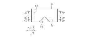
- FIG. 12B is a sectional view taken along line A9-A9 in FIG. 12A.
- FIG. 12B is a sectional view taken along line B9-B9 in FIG. 12A.
- FIG. 12B is a sectional view taken along line C9-C9 in FIG. 12A.
- FIG. 13B is a sectional view taken along line A10-A10 in FIG. 13A.
- FIG. 13B is a sectional view taken along line B10-B10 in FIG. 13A.
- FIG. 13C is a cross-sectional view taken along the line C10-C10 of FIG. 13A. It is a side view which shows the nozzle for an irregular cross-section glass fiber manufacture which concerns on the 11th Embodiment of this invention.
- FIG. 14B is a sectional view taken along line A11-A11 of FIG. 14A.
- FIG. 14B is a sectional view taken along the line B11-B11 of FIG. 14A.
- FIG. 14B is a cross-sectional view taken along the line C11-C11 of FIG. 14A. It is a side view which shows the nozzle for irregular cross-section glass fiber manufacture which concerns on the 12th Embodiment of this invention.
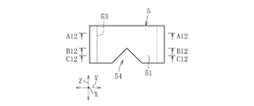
- FIG. 15B is a sectional view taken along line A12-A12 of FIG. 15A.
- FIG. 15B is a sectional view taken along the line B12-B12 of FIG. 15A.
- FIG. 15C is a sectional view taken along line C12-C12 of FIG. 15A. It is sectional drawing which shows typically an example of an irregular cross-section glass fiber. It is sectional drawing which shows typically an example of an irregular cross-section glass fiber.
- 6 is a side view showing a nozzle according to Comparative Example 1.
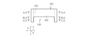
- FIG. FIG. 17B is a sectional view taken along line A13-A13 of FIG. 17A.
- FIG. 17B is a sectional view taken along line B13-B13 of FIG. 17A.
- FIG. 17B is a sectional view taken along line C13-C13 of FIG. 17A.
- 10 is a side view showing a nozzle according to Comparative Example 2.
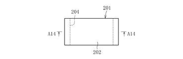
- FIG. FIG. 18B is a cross-sectional view taken along line A14-A14 of FIG. 18A.
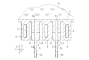
- the modified cross-section glass fiber manufacturing apparatus includes a glass melting furnace 1, a forehearth 2 connected to the glass melting furnace 1, and a feeder 3 connected to the forehearth 2.
- a glass melting furnace 1 a glass melting furnace 1
- a forehearth 2 connected to the glass melting furnace 1
- a feeder 3 connected to the forehearth 2.
- the X direction and the Y direction are horizontal directions
- the Z direction is a vertical direction (hereinafter the same).
- the molten glass G is supplied from the glass melting furnace 1 to the feeder 3 through the forehearth 2 and is stored in the feeder 3. Although one feeder 3 is illustrated in FIG. 1, a plurality of feeders 3 may be connected to the glass melting furnace 1.
- the molten glass G is made of E glass, but may be other glass materials such as D glass, S glass, AR glass, and C glass.
- the bottom of the feeder 3 is constituted by a bushing 4.
- the bushing 4 is attached to the feeder 3 via a bushing block or the like.
- a plurality of nozzles 5 are provided at the bottom of the bushing 4.
- a cooling pipe 6 as a cooling means is provided in the vicinity of each nozzle 5.
- Molten glass G stored in the feeder 3 is drawn downward from a plurality of nozzles 5 provided in the bushing 4 to produce glass fibers (monofilaments) Gm.
- the viscosity of the molten glass G at the molding temperature is set in the range of 10 2.0 to 10 3.5 dPa ⁇ s (preferably 10 2.5 to 10 3.3 dPa ⁇ s).
- the viscosity of the molten glass G at the molding temperature is the viscosity of the molten glass G at the position flowing into the nozzle 5.
- a bundling agent is applied to the surface of the glass fiber Gm by an applicator (not shown), and 100 to 10,000 pieces are spun into one strand Gs.
- the spun strand Gs is wound as a fiber bundle Gr on the bobbin 7 of the winding device.
- the strand Gs is cut into a predetermined length of about 1 to 20 mm, for example, and used as a chopped strand.
- At least a part of the glass melting furnace 1, the forehearth 2, the feeder 3, the bushing 4, the nozzle 5 and the cooling pipe 6 is made of platinum or a platinum alloy (for example, platinum rhodium alloy).
- the feeder 3 and the bushing 4 may be heated by electric heating or the like.
- the nozzle 5 includes a pair of short walls (first wall portions) 51 that face each other in the Y direction and a pair of short walls that face each other in the Y direction.
- a wall portion (second wall portion) 52 and a flat nozzle hole 53 defined by a long wall portion 51 and a short wall portion 52 are provided.
- Each long wall 51 is provided with a notch 54, and a part of the nozzle hole 53 communicates with the external space of the nozzle 5 through the notch 54.
- the major axis direction of the nozzle hole 53 coincides with the Y direction
- the minor axis direction of the nozzle hole 53 coincides with the X direction.
- the X direction dimension of the short wall part 52 is shorter than the Y direction dimension of the long wall part 51.
- the dimensional relationship between the wall portions 51 and 52 is not particularly limited.
- the cooling pipe 6 has a cooling effect by circulating cooling water F as a fluid therein.
- the cooling pipe 6 is a plate-like body and is arranged so that its plate surface is along the vertical direction.
- the cooling pipe 6 is integrally provided at the bottom of the bushing 4, but may be provided separately from the bottom of the bushing 4.
- the cooling pipe 6 may be a circular tubular body.
- the height position of the cooling pipe 6 can be appropriately adjusted according to the cooling conditions of the molten glass G.
- the cooling pipe 6 may be disposed above the tip of the nozzle 5 so as not to directly face the molten glass G drawn from the nozzle 5, or the molten glass G drawn from the nozzle 5 and the nozzle 5. It may be arranged so as to straddle both.
- the cooling means is not limited to the cooling pipe 6 and may be a cooling fin that induces an air flow and exerts a cooling action.
- the cooling means is not an essential configuration and may be omitted.
- a plurality of nozzle rows L are arranged in parallel at intervals in the X direction at the bottom of the bushing 4.
- Each nozzle row L is configured by arranging a plurality of nozzles 5 with the major axis direction of the nozzle holes 53 oriented in the Y direction on the same straight line extending in the Y direction.
- the cooling pipe 6 is arranged in parallel with the nozzle row L between the nozzle rows L adjacent in the X direction. Thereby, the cooling pipe 6 faces the notch 54 of the nozzle 5, and the molten glass G flowing through the nozzle 5 through the notch 54 is cooled. Specifically, the molten glass G is rapidly cooled from the temperature of 1000 ° C. or higher by the cooling pipe 6 at the tip of the nozzle 5.
- the cooling pipe 6 also has a function of cooling the bushing 4 and the nozzle 5 and suppressing the thermal deterioration thereof to improve durability.
- the opening width W in the Y direction gradually increases as the cutout portion 54 provided in each long wall portion 51 of the nozzle 5 moves toward the tip side.
- the notches 54 and 54 provided in each of the long wall portions 51 and 51 have a triangular shape with the same dimensions, and only the central portion of the long wall portion 51 excluding both end portions in the Y direction. Is formed.
- the notch 54 has an isosceles triangle shape (including an equilateral triangle shape) having a vertex T1 on the center line M1 of the long wall portion 51 and symmetric with respect to the center line M1.
- the apex angle ⁇ 1 is, for example, 40 to 150 ° (preferably 60 to 120 °).
- the nozzle hole 53 is a flat oval (or ellipse), and is a fixed shape in the Z direction. As shown in FIG. 4D, at the tip of the nozzle 5, the nozzle hole 53 has a ratio (a / b) of the X direction dimension (short diameter dimension) b to the Y direction dimension (major diameter dimension) a of 1.5 to 20. (Preferably 3 to 10).
- the glass fiber Gm having an irregular cross section having a non-circular cross section such as a flat shape can be stably formed. In other words, the variation in the cross-sectional shape of the manufactured glass fiber Gm is reduced.
- the shape of the base end portion is the same as the shape of the tip portion. May be different or different.
- the shape of the notch 54 of the nozzle 5 can be variously modified. Hereinafter, the modified example will be described.
- the cutout portions 54, 54 provided in the long wall portions 51, 51 are triangular in the same dimension, and in the Y direction on the proximal end side of the long wall portion 51, In addition to being formed in a partial region, it may be formed in the entire region in the Y direction on the distal end side of the long wall portion 51.
- the notch 54 has an isosceles triangle shape having a vertex T2 on the center line M2 of the long wall portion 51 and symmetric with respect to the center line M2.
- the apex angle ⁇ 2 is, for example, 90 to 165 ° (preferably 100 to 150 °).
- the nozzle hole 53 is a flat oval and has a constant shape in the Z direction.
- the notches 54 and 54 provided in the respective long wall portions 51 and 51 have an arcuate shape with the same dimensions, and both ends of the long wall portion 51 in the Y direction are formed. You may form only in the center part except.
- the cutout portion 54 has a vertex T3 on the center line M3 of the long wall portion 51 and is symmetrical with respect to the center line M3 (the length of the chord is a diameter). Bow shape).
- the curvature radius R3 is, for example, 0.5 to less than 5 mm (preferably 2 to 4 mm).
- the notch part 54 may be an arc shape in which the length of the string is less than the diameter of the circle, or may be a concave curve that is not an arc.
- the nozzle hole 53 is a flat oval shape, and is a fixed shape in the Z direction.
- the cutout portions 54, 54 provided in the long wall portions 51, 51 have the same arch shape, and in the Y direction on the proximal end side of the long wall portion 51. In addition to being formed in a partial region, it may be formed in the entire region in the Y direction on the distal end side of the long wall portion 51.
- the notch portion 54 has a vertex T4 on the center line M4 of the long wall portion 51, and is symmetrical with respect to the center line M4, and the length of the chord is less than the diameter of the circle.
- the curvature radius R4 is, for example, 5 to 20 mm (preferably 5 to 10 mm).
- the notch 54 may be semicircular or a concave curve that is not an arc.
- the nozzle hole 53 is a flat oval shape, and is a fixed shape in the Z direction.
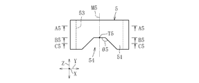
- the notches 54 and 54 provided in the respective long wall portions 51 and 51 are trapezoidal with the same dimensions, and both ends of the long wall portion 51 in the Y direction are formed. You may form only in the center part except.
- the cutout portion 54 has an isosceles trapezoidal shape (upper surface) having a center point T5 of the upper base on the center line M5 of the long wall portion 51 and symmetrical with respect to the center line M5. The bottom is shorter than the bottom).
- the inner angle ⁇ 5 is, for example, more than 90 ° to 160 ° (preferably 110 ° to 150 °).
- the nozzle hole 53 is a flat oval and has a constant shape in the Z direction.
- the notches 54 and 54 provided in the long wall portions 51 and 51 are trapezoidal with the same dimensions, and the base wall side of the long wall portion 51 is in the Y direction. In addition to being formed in a partial region, it may be formed in the entire region in the Y direction on the distal end side of the long wall portion 51.
- the notch 54 has an isosceles trapezoidal shape having an upper base center point T6 on the center line M6 of the long wall portion 51 and symmetrical with respect to the center line M6. .
- the inner angle ⁇ 6 is, for example, more than 90 ° to 160 ° (preferably 110 ° to 150 °).
- the nozzle hole 53 is a flat oval and has a constant shape in the Z direction.
- the shape of the nozzle hole 53 can be variously modified. An embodiment as a modification thereof will be described below.
- the shape of the notch 54 is described by taking the triangular shape shown in FIG. 4A as an example, but is not limited to this, and has the shape of the notch 54 as in the above-described modification. There may be.
- the nozzle hole 53 is provided in a slit portion 53a elongated in the Y direction and at both ends of the slit portion 53a, and in the X direction more than the slit portion 53a. You may have the enlarged part 53b with a large dimension.
- the nozzle hole 53 has a dumbbell shape in which the enlarged portion 53b has a circular shape.
- the shape of the nozzle hole 53 may be changed so that the flow path area in the Y direction is substantially the same at the tip of the nozzle 5 where the notch 54 is formed (FIG. 10D).
- the nozzle hole 53 is oval). In this case, it is assumed that the flow path of the nozzle hole 53 at the proximal end portion shown in FIGS. 10B and 10C is all included in the flow path of the nozzle hole 53 at the distal end portion shown in FIG. 10D. Note that the nozzle hole 53 may also have the same dumbbell shape at the tip of the nozzle 5.
- the nozzle hole 53 may have an area changing portion 53c in which the flow path area gradually increases from the center in the Y direction toward both end portions. Good.
- the nozzle hole 53 has a shape in which the vertices of two isosceles triangles abut each other and the bisector of the apex angle is arranged on the same straight line (Y direction).
- the shape of the nozzle hole 53 may be changed so that the flow area in the Y direction is substantially the same at the tip of the nozzle 5 where the notch 54 is formed (FIG. 11D).
- the nozzle hole 53 may have a rectangular shape having a constant shape in the Z direction.
- the nozzle hole 53 may be divided into a plurality of nozzle holes 53d at the base end portion of the nozzle 5.
- the nozzle hole 53d has a circular shape, and is provided at an interval between both ends and the center in the Y direction.
- the shape of the nozzle hole 53 may be changed so that the plurality of divided nozzle holes 53d merge together at the tip of the nozzle 5 where the notch 54 is formed ( In the example shown, an oval).
- the flow path of the nozzle hole 53 at the proximal end portion shown in FIGS. 13B and 13C is all included in the flow path of the nozzle hole 53 at the distal end portion shown in FIG. 13D.
- the nozzle hole 53 has a large area portion 53e having a large flow area and a small area portion 53f having a small flow area alternately in the Y direction. You may have.
- the circular large area part 53e is provided in the both ends and center part of a Y direction, and it touches the large area part 53e of both sides between the adjacent large area parts 53e.
- a circular small area portion 53f is provided.
- the shape of the nozzle hole 53 may be changed so that the flow area in the Y direction is substantially the same at the tip of the nozzle 5 where the notch 54 is formed (FIG. 14D).
- the nozzle hole 53 may have an area changing portion 53g in which the flow path area gradually decreases from the center in the Y direction toward both end portions.
- the shape of the nozzle hole 53 is a diamond shape.
- the flow path of the nozzle hole 53 at the proximal end portion shown in FIGS. 15B and 15C is all included in the flow path of the nozzle hole 53 at the distal end portion shown in FIG. 15D.
- the glass fiber Gm produced by drawing the molten glass G from the nozzle 5 of the production apparatus as described above has an irregular shape in which the cross section (transverse cross section perpendicular to the drawing direction) forms a flat shape. It has a cross section.
- the cross-sectional flatness ratio (A / B) is in the range of 1.5 to 20 (preferably 3 to 10). It has become.
- the value obtained by dividing the variation ⁇ of the flat ratio of the glass fiber Gm by the average value of the flat ratio is 15% or less. That is, it is possible to obtain glass fibers Gm with little variation.
- the value obtained by dividing the variation ⁇ of the flat ratio of the glass fiber Gm by the average value of the flat ratio in percentage is more preferably 10% or less.
- the flatness ratio of the glass fiber Gm is measured as follows. First, in order to observe the cross section of the glass fiber Gm, the glass fiber Gm is vertically embedded in a room temperature curable resin technobit manufactured by Kulzer and polished after the resin is cured. Next, while observing the cross-sectional shape of the glass fiber Gm with a polarizing microscope, the lengths of the major and minor axes of the glass fiber Gm observed using the image processing software WinROOF manufactured by Mitani Corporation are measured, and the flat ratio Calculate (major axis / minor axis). The variation ⁇ of the flat ratio is a standard deviation calculated from the flat ratio obtained by observing the cross section of 50 glass fibers Gm.
- this invention is not limited to said embodiment, It can implement in a various form.
- Example 1 Spinning is performed at a temperature at which the viscosity of the molten glass is 10 3.0 dPa ⁇ s using a bushing in which 100 nozzles 5 shown in FIGS. 8A to 8D are arranged in a straight line so that the long wall portions 51 are parallel to each other. It was.
- the average of the flatness ratio (major axis / minor axis) was 4.8, and the variation ⁇ was 0.14.
- the value (percentage) obtained by dividing ⁇ by the average value of the aspect ratio was 2.9%.
- no deformation of the nozzle was observed after one week of production.
- Example 2 Spinning is performed at a molding temperature at which the viscosity of the molten glass is 10 3.0 dPa ⁇ s using a bushing in which 100 nozzles 5 shown in FIGS. 15A to 15D are arranged in a straight line so that the long wall portions 51 are parallel to each other. went.
- the average aspect ratio was 2.8, and the variation ⁇ was 0.24.
- the value (percentage) obtained by dividing ⁇ by the average value of the aspect ratio was 8.5%.
- no deformation of the nozzle was observed after one week of production.
- Example 3 8A to 8D, using a bushing in which 100 nozzles 5 arranged in a straight line so that the long wall portion 51 is parallel, and cooling fins arranged in parallel to the long wall portion 51 of the nozzle 5, Spinning was performed at a molding temperature at which the viscosity of the molten glass was 10 3.0 dPa ⁇ s.
- the average flatness ratio was 5.0
- the variation ⁇ was 0.10.
- the value (percentage) obtained by dividing ⁇ by the average value of the aspect ratio was 2%.
- no deformation of the nozzle was observed after one week of production.
- the nozzle 101 shown in FIGS. 17A to 17D is spun at a molding temperature at which the viscosity of the molten glass is 10 3.0 dPa ⁇ s, using 100 bushings provided on a straight line so that the long wall portion 102 is parallel. went.
- the nozzle 101 includes a long wall portion 102 and a short wall portion 103, and has a rectangular cutout portion 105 in the long wall portion 102.
- the nozzle hole 104 is oval and has a fixed shape in the vertical direction.
- the average flatness ratio was 2.2, and the variation ⁇ was 0.27.
- the value (percentage) obtained by dividing ⁇ by the average value of the aspect ratio was 12.2%.
- nozzle deformation was observed after one week of production.
- the nozzle 201 shown in FIGS. 18A to 18B is spun at a molding temperature at which the viscosity of the molten glass is 10 3.0 dPa ⁇ s by using 100 bushings provided on a straight line so that the long wall portion 202 is parallel. went.
- the nozzle 201 includes a long wall portion 202 and a short wall portion 203, but neither the long wall portion 202 nor the short wall portion 203 has a notch.
- the nozzle hole 204 has an oval shape and is constant in the vertical direction.
- the average aspect ratio was 1.8, and the variation ⁇ was 0.11.
- the value (percentage) obtained by dividing ⁇ by the average value of the aspect ratio was 6%.
- the nozzle tip was not deformed even after one week of production.
Landscapes
- Engineering & Computer Science (AREA)
- Chemical & Material Sciences (AREA)
- Mechanical Engineering (AREA)
- Textile Engineering (AREA)
- Life Sciences & Earth Sciences (AREA)
- General Life Sciences & Earth Sciences (AREA)
- Geochemistry & Mineralogy (AREA)
- Manufacturing & Machinery (AREA)
- Materials Engineering (AREA)
- Organic Chemistry (AREA)
- Manufacture, Treatment Of Glass Fibers (AREA)
- Spinning Methods And Devices For Manufacturing Artificial Fibers (AREA)
Abstract
異形断面ガラス繊維製造用ノズル5は、溶融ガラスGが流出する先端部において、X方向で対向する一対の長壁部51と、X方向と直交するY方向で対向し、かつ、X方向寸法が長壁部51のY方向寸法よりも短い一対の短壁部52と、長壁部51と短壁部52で区画形成された扁平状のノズル孔53と、を備える。それぞれの長壁部51には、先端側に向かうに連れてY方向の開口幅Wが漸次拡大する切欠き部54が設けられている。
Description
本発明は、異形断面ガラス繊維の製造技術の改良に関するものである。
断面が長円形や楕円形のような扁平形状などの非円形断面を有する異形断面ガラス繊維は、樹脂と混合して複合化した場合に高い補強効果を実現できることから、さまざまな分野で利用されている。
この種の異形断面ガラス繊維は、ノズルから溶融ガラスを引き出しながら冷却することにより製造されるのが一般的である。この際、ノズル先端部のノズル孔の形状が製造されるガラス繊維の断面形状の基礎を形作ることから、異形断面ガラス繊維の製造する場合、ノズル先端部においてノズル孔が扁平状とされることが多い。
しかしながら、扁平状のノズル孔を有するノズルを使用したとしても、ノズルから引き出される溶融ガラスの粘度が低すぎれば、ノズル先端部の直下で表面張力により溶融ガラスの断面が丸くなるように形成されやすく、所期の異形断面ガラス繊維を製造することができなくなる。
そこで、例えば、特許文献1の図18~20に開示のノズルでは、溶融ガラスが流出するノズル先端部において、扁平状のノズル孔の短径方向で対向する一対の長壁部のそれぞれに凹状の切欠き部を設け、この凹状の切欠き部により冷却して溶融ガラスの粘度を調整している。
ところで、特許文献1の図18~20に開示の切欠き部は、基端側(溶融ガラスの流入側)の開口幅と先端側(溶融ガラスの流出側)の開口幅が実質的に同じ矩形状である。そのため、切欠き部を設けたノズル先端部の強度が必然的に弱くなる。特に、矩形状の切欠き部の開口面積を大きくするために、長壁部の略全域に矩形状の切欠き部を設けた場合、切欠き部を除くノズル先端部の残余部が、実質的にノズル孔の長径側で対向する一対の短壁部のみになるため、ノズル先端部の強度低下はより顕著になる。
しかしながら、ノズルの内部には高温の溶融ガラスが流通するとともに周辺温度も高いため、上述のようにノズル先端部の強度が低いと、短壁部が外側に広がるなどの熱変形が生じるおそれがある。この場合、ノズル先端部におけるノズル孔の形状変形を伴うことから、成形されるガラス繊維の形状にばらつきが大きくなり、安定的な成形が難しくなる。
以上の実情に鑑み、本発明は、ノズルの熱変形を抑えつつ成形時の溶融ガラスの粘度を適正に調整し、異形断面ガラス繊維を安定的に成形することを課題とする。
上記課題を解決するために創案された本発明に係る異形断面ガラス繊維製造用ノズルは、溶融ガラスが流出する先端部において、扁平状のノズル孔と、ノズル孔の短径方向で対向する一対の第1の壁部と、ノズル孔の長径方向で対向する一対の第2の壁部と、を備えた異形断面ガラス繊維製造用ノズルであって、一対の第1の壁部のそれぞれは、先端側に向かうに連れて長径方向の開口幅が漸次拡大する凹状の切欠き部を有することを特徴とする。
このような構成によれば、切欠き部の開口幅が先端側に向かうに連れて漸次拡大するため、ノズル先端部において、切欠き部を除く第1の壁部の残余部の基端側面積はその先端側面積よりも大きくなる。その結果、基端側における第1の壁部の強度が十分確保され、切欠き部を設けたノズル先端部が熱変形しにくくなる。そして、このようにノズル強度を確保した状態で、先端側の切欠き部の開口幅は大きくなるので、切欠き部の開口面積も十分に確保できる。そのため、両側の切欠き部を通じて溶融ガラスを十分に冷却することができる。その結果、ノズル先端部における溶融ガラスの粘度が高くなり、ノズルから引き出される溶融ガラスの断面が表面張力によって丸まりにくくなる。したがって、上記構成を備えたノズルによって異形断面ガラス繊維を製造すれば、扁平形状などの非円形断面を有する異形断面ガラス繊維を安定的に成形することが可能となる。特に、一対の第1の壁部のそれぞれに切欠き部を有するため、ばらつきが少ない異形断面ガラス繊維を得ることができる。
上記の構成において、切欠き部は、第1の壁部のうち、長径方向の中央部のみに形成されていることが好ましい。このようにすれば、第1の壁部の長径方向の両端部には切欠き部が形成されない。そのため、第1の壁部の先端側の強度も確保しやすくなり、ノズルの熱変形をより確実に防止することができる。
上記の構成において、切欠き部が、三角形状、台形状、および弦と弧からなる弓形状の中から選択された1つの形状であってもよい。特に、台形状や半円形などの弓形状が、切欠き部に鋭角部が形成されないため好ましい。
上記課題を解決するために創案された本発明に係る異形断面ガラス繊維製造装置は、上記の構成を適宜備えたノズルが底部に複数設けられたブッシングを備えていることを特徴とする。このような構成によれば、既に述べた対応する構成と同様の効果を享受することができる。
上記の構成において、ノズルの切欠き部に対向するように、冷却手段が配置されていることが好ましい。このようにすれば、切欠き部を通じて溶融ガラスをより効率的に冷却することができる。
上記の構成において、長径方向を同一方向に向けた複数のノズルを長径方向に延びる同一直線上に配置してなるノズル列が、平行に複数列配置されるとともに、冷却手段が、隣接するノズル列の間に、ノズル列と平行に配置されていてもよい。このようにすれば、冷却手段の数を減らしつつ、ブッシングにノズルを密に配置できるため、異形断面ガラス繊維を効率よく製造することができる。
上記課題を解決するために創案された本発明に係る異形断面ガラス繊維製造方法は、扁平状のノズル孔と、ノズル孔の短径方向で対向する一対の第1の壁部と、ノズル孔の長径方向で対向する一対の第2の壁部と、を備えたノズルを用いて異形断面ガラス繊維を製造する異形断面ガラス繊維製造方法であって、ノズルは、一対の第1の壁部のそれぞれに、先端側に向かうに連れて長径方向の開口幅が漸次拡大する凹状の切欠き部を有することを特徴とする。このような構成によれば、既に述べた対応する構成と同様の効果を享受することができる。
上記の構成において、溶融ガラスはEガラスであってもよい。このようにすれば、Eガラスは失透しにくいガラスであるため、異形断面ガラス繊維の生産性が向上するという利点がある。
上記の構成において、成形温度において、溶融ガラスは、102.0~103.5dPa・sの粘度を有することが好ましい。すなわち、103.5dPa・s以下であれば、溶融ガラスの粘度が高くなりすぎないため、ガラス繊維の成形性を良好に維持することができる。また、102.0dPa・s以上であれば、溶融ガラスの粘度が低くなりすぎないため、溶融ガラスが表面張力によって円形断面に戻ろうとする力が弱められ、ガラス繊維の扁平比(長径寸法/短径寸法)を高めることができる。
以上の本発明によれば、ノズルの熱変形を抑えつつ成形時の溶融ガラスの粘度を適正に調整し、異形断面ガラス繊維を安定的に成形することができる。
以下、本発明の実施形態について、添付図面に基づいて説明する。
(異形断面ガラス繊維の製造装置及び製造方法の一実施形態)
図1に示すように、本実施形態に係る異形断面ガラス繊維製造装置は、ガラス溶融炉1と、ガラス溶融炉1に接続されたフォアハース2と、フォアハース2に接続されたフィーダー3とを備えている。ここで、図1に示すXYZからなる直交座標系において、X方向及びY方向は水平方向であり、Z方向が鉛直方向である(以下、同様)。
図1に示すように、本実施形態に係る異形断面ガラス繊維製造装置は、ガラス溶融炉1と、ガラス溶融炉1に接続されたフォアハース2と、フォアハース2に接続されたフィーダー3とを備えている。ここで、図1に示すXYZからなる直交座標系において、X方向及びY方向は水平方向であり、Z方向が鉛直方向である(以下、同様)。
溶融ガラスGは、ガラス溶融炉1からフォアハース2を通じてフィーダー3に供給されると共に、フィーダー3内に貯留される。図1では1つのフィーダー3を図示しているが、ガラス溶融炉1には複数のフィーダー3が接続されていてもよい。
この実施形態では、溶融ガラスGはEガラスからなるが、Dガラス、Sガラス、ARガラス、Cガラス等の他のガラス材質であってもよい。
フィーダー3の底部は、ブッシング4によって構成されている。ブッシング4は、ブッシングブロック等を介してフィーダー3に取り付けつけられている。ブッシング4の底部には、複数のノズル5が設けられている。各ノズル5の近傍には冷却手段としての冷却管6が設けられている。
ブッシング4に設けられた複数のノズル5からフィーダー3内に貯留された溶融ガラスGが下方に引き出され、ガラス繊維(モノフィラメント)Gmが製造される。この際、成形温度における溶融ガラスGの粘度は、102.0~103.5dPa・s(好ましくは102.5~103.3dPa・s)の範囲内に設定される。なお、成形温度における溶融ガラスGの粘度は、ノズル5に流入する位置における溶融ガラスGの粘度とする。ガラス繊維Gmの表面には、図示しないアプリケータにより集束剤が塗布されるとともに、100~10000本が1本のストランドGsに紡糸される。紡糸されたストランドGsは、巻き取り装置のボビン7に繊維束Grとして巻き取られる。ストランドGsは、例えば、1~20mm程度の所定長に切断され、チョップドストランドとして利用される。
ガラス溶融炉1、フォアハース2、フィーダー3、ブッシング4、ノズル5及び冷却管6は、少なくとも一部が白金又は白金合金(例えば、白金ロジウム合金)により形成されている。
溶融ガラスGの粘度を調整するために、フォアハース2、フィーダー3およびブッシング4の中から選ばれた一又は複数の要素を通電加熱などで加熱してもよい。
図2及び図3に示すように、ノズル5は、先端部(下側部分)において、X方向で対向する一対の長壁部(第1の壁部)51と、Y方向で対向する一対の短壁部(第2の壁部)52と、長壁部51と短壁部52で区画形成された扁平状のノズル孔53とを備えている。各々の長壁部51には切欠き部54が設けられており、ノズル孔53の一部が切欠き部54を通じてノズル5の外部空間に連通している。この実施形態では、ノズル孔53の長径方向はY方向と一致しており、ノズル孔53の短径方向はX方向と一致している。また、この実施形態では、短壁部52のX方向寸法は長壁部51のY方向寸法よりも短い。もちろん、壁部51,52のこれら寸法関係は特に限定されるものではない。
冷却管6は、その内部に流体としての冷却水Fを循環させて冷却作用を及ぼすようになっている。冷却管6は、板状体であって、その板面が上下方向に沿うように配置されている。なお、冷却管6は、この実施形態では、ブッシング4の底部に一体的に設けられているが、ブッシング4の底部から離して設けてもよい。また、冷却管6は、円管状体であってもよい。冷却管6の高さ位置は、溶融ガラスGの冷却条件に応じて適宜調整することができる。例えば、冷却管6は、ノズル5から引き出された溶融ガラスGに直接対面しないようにノズル5の先端よりも上方に配置されていてもよいし、ノズル5とノズル5から引き出された溶融ガラスGの双方に跨るように配置されていてもよい。冷却手段は、冷却管6に限らず、空気流を誘導して冷却作用を及ぼす冷却フィンなどであってもよい。冷却手段は、必須の構成ではなく省略してもよい。
この実施形態では、図3に示すように、ブッシング4の底部において、複数のノズル列LがX方向に間隔を置いて平行に配置されている。各ノズル列Lは、ノズル孔53の長径方向をY方向に向けた複数のノズル5をY方向に延びる同一直線上に配置することで構成される。冷却管6は、X方向に隣接するノズル列Lの間に、ノズル列Lと平行に配置されている。これにより、冷却管6がノズル5の切欠き部54に対向し、切欠き部54を通じてノズル5内を流通する溶融ガラスGが冷却されるようになっている。具体的には、ノズル5の先端部において、溶融ガラスGは冷却管6によって1000℃以上の温度から急激に冷却される。なお、冷却管6は、ブッシング4やノズル5を冷却し、これらの熱劣化を抑えて耐久性を高める機能もある。
(ノズルの第1の実施形態)
図4A~図4Dに示すように、ノズル5の各々の長壁部51に設けられた切欠き部54は、先端側に向かうに連れてY方向の開口幅Wが漸次拡大する。この実施形態では、各々の長壁部51,51に設けられた切欠き部54,54は、同一寸法の三角形状であり、かつ、長壁部51のうちY方向の両端部を除く中央部のみに形成されている。詳細には、切欠き部54は、長壁部51の中心線M1上に頂点T1を有し、かつ、中心線M1に対して対称な二等辺三角形状(正三角形状を含む)である。頂角θ1は、例えば40~150°(好ましくは60~120°)である。また、この実施形態では、ノズル孔53は、扁平な長円形(又は楕円)であり、Z方向で一定の形状である。図4Dに示すように、ノズル5の先端部において、ノズル孔53は、Y方向寸法(長径寸法)aに対するX方向寸法(短径寸法)bの比率(a/b)が1.5~20(好ましくは3~10)の範囲である。
図4A~図4Dに示すように、ノズル5の各々の長壁部51に設けられた切欠き部54は、先端側に向かうに連れてY方向の開口幅Wが漸次拡大する。この実施形態では、各々の長壁部51,51に設けられた切欠き部54,54は、同一寸法の三角形状であり、かつ、長壁部51のうちY方向の両端部を除く中央部のみに形成されている。詳細には、切欠き部54は、長壁部51の中心線M1上に頂点T1を有し、かつ、中心線M1に対して対称な二等辺三角形状(正三角形状を含む)である。頂角θ1は、例えば40~150°(好ましくは60~120°)である。また、この実施形態では、ノズル孔53は、扁平な長円形(又は楕円)であり、Z方向で一定の形状である。図4Dに示すように、ノズル5の先端部において、ノズル孔53は、Y方向寸法(長径寸法)aに対するX方向寸法(短径寸法)bの比率(a/b)が1.5~20(好ましくは3~10)の範囲である。
このような構成によれば、ノズル5の切欠き部54に起因する形状変形を抑えつつ、切欠き部54の開口面積も十分に確保できる。したがって、扁平形状などの非円形断面を有する異形断面を有するガラス繊維Gmを安定的に成形可能となる。換言すれば、製造されたガラス繊維Gmの断面形状のばらつきが小さくなる。
ノズル5は、先端部において長壁部51と短壁部52によって区画形成された扁平状のノズル孔53を有していれば、基端部(上側部分)の形状は先端部の形状と同じであってもよいし、異なっていてもよい。
ノズル5の切欠き部54の形状は種々変形可能である。以下、その変形例を説明する
(ノズルの第2の実施形態)
図5A~図5Dに示すように、各々の長壁部51,51に設けられた切欠き部54,54は、同一寸法の三角形状であり、かつ、長壁部51の基端側ではY方向の一部領域に形成されるとともに、長壁部51の先端側ではY方向の全領域に形成されていてもよい。詳細には、この実施形態では、切欠き部54は、長壁部51の中心線M2上に頂点T2を有し、かつ、中心線M2に対して対称な二等辺三角形状である。頂角θ2は、例えば90~165°(好ましくは100~150°)である。なお、この実施形態では、ノズル孔53は扁平な長円形であり、Z方向で一定の形状である。
図5A~図5Dに示すように、各々の長壁部51,51に設けられた切欠き部54,54は、同一寸法の三角形状であり、かつ、長壁部51の基端側ではY方向の一部領域に形成されるとともに、長壁部51の先端側ではY方向の全領域に形成されていてもよい。詳細には、この実施形態では、切欠き部54は、長壁部51の中心線M2上に頂点T2を有し、かつ、中心線M2に対して対称な二等辺三角形状である。頂角θ2は、例えば90~165°(好ましくは100~150°)である。なお、この実施形態では、ノズル孔53は扁平な長円形であり、Z方向で一定の形状である。
(ノズルの第3の実施形態)
図6A~図6Dに示すように、各々の長壁部51,51に設けられた切欠き部54,54は、同一寸法の弓形状であり、かつ、長壁部51のうちY方向の両端部を除く中央部のみに形成されていてもよい。詳細には、この実施形態では、切欠き部54は、長壁部51の中心線M3上に頂点T3を有し、かつ、中心線M3に対して対称な半円形状(弦の長さが直径となる弓形状)である。曲率半径R3は、例えば0.5~5mm未満(好ましくは2~4mm)である。なお、切欠き部54は、弦の長さが円の直径未満となる弓形状であってもよいし、円弧ではない凹状の曲線であってもよい。また、この実施形態では、ノズル孔53は扁平な長円形であり、Z方向で一定の形状である。
図6A~図6Dに示すように、各々の長壁部51,51に設けられた切欠き部54,54は、同一寸法の弓形状であり、かつ、長壁部51のうちY方向の両端部を除く中央部のみに形成されていてもよい。詳細には、この実施形態では、切欠き部54は、長壁部51の中心線M3上に頂点T3を有し、かつ、中心線M3に対して対称な半円形状(弦の長さが直径となる弓形状)である。曲率半径R3は、例えば0.5~5mm未満(好ましくは2~4mm)である。なお、切欠き部54は、弦の長さが円の直径未満となる弓形状であってもよいし、円弧ではない凹状の曲線であってもよい。また、この実施形態では、ノズル孔53は扁平な長円形であり、Z方向で一定の形状である。
(ノズルの第4の実施形態)
図7A~図7Dに示すように、各々の長壁部51,51に設けられた切欠き部54,54は、同一寸法の弓形状であり、かつ、長壁部51の基端側ではY方向の一部領域に形成されるとともに、長壁部51の先端側ではY方向の全領域に形成されていてもよい。詳細には、この実施形態では、切欠き部54は、長壁部51の中心線M4上に頂点T4を有し、かつ、中心線M4に対して対称で弦の長さが円の直径未満となる弓形状である。曲率半径R4は、例えば5~20mm(好ましくは5~10mm)である。なお、切欠き部54は、半円形状であってもよいし、円弧ではない凹状の曲線であってもよい。また、この実施形態では、ノズル孔53は扁平な長円形であり、Z方向で一定の形状である。
図7A~図7Dに示すように、各々の長壁部51,51に設けられた切欠き部54,54は、同一寸法の弓形状であり、かつ、長壁部51の基端側ではY方向の一部領域に形成されるとともに、長壁部51の先端側ではY方向の全領域に形成されていてもよい。詳細には、この実施形態では、切欠き部54は、長壁部51の中心線M4上に頂点T4を有し、かつ、中心線M4に対して対称で弦の長さが円の直径未満となる弓形状である。曲率半径R4は、例えば5~20mm(好ましくは5~10mm)である。なお、切欠き部54は、半円形状であってもよいし、円弧ではない凹状の曲線であってもよい。また、この実施形態では、ノズル孔53は扁平な長円形であり、Z方向で一定の形状である。
(ノズルの第5の実施形態)
図8A~図8Dに示すように、各々の長壁部51,51に設けられた切欠き部54,54は、同一寸法の台形状であり、かつ、長壁部51のうちY方向の両端部を除く中央部のみに形成されていてもよい。詳細には、この実施形態では、切欠き部54は、長壁部51の中心線M5上に上底の中心点T5を有し、かつ、中心線M5に対して対称な等脚台形状(上底が下底よりも短い)である。内角θ5(上底の両側の内角)は、例えば90°超~160°(好ましくは110°~150°)である。なお、この実施形態では、ノズル孔53は扁平な長円形であり、Z方向で一定の形状である。
図8A~図8Dに示すように、各々の長壁部51,51に設けられた切欠き部54,54は、同一寸法の台形状であり、かつ、長壁部51のうちY方向の両端部を除く中央部のみに形成されていてもよい。詳細には、この実施形態では、切欠き部54は、長壁部51の中心線M5上に上底の中心点T5を有し、かつ、中心線M5に対して対称な等脚台形状(上底が下底よりも短い)である。内角θ5(上底の両側の内角)は、例えば90°超~160°(好ましくは110°~150°)である。なお、この実施形態では、ノズル孔53は扁平な長円形であり、Z方向で一定の形状である。
(ノズルの第6の実施形態)
図9A~図9Dに示すように、各々の長壁部51,51に設けられた切欠き部54,54は、同一寸法の台形状であり、かつ、長壁部51の基端側ではY方向の一部領域に形成されるとともに、長壁部51の先端側ではY方向の全領域に形成されていてもよい。詳細には、この実施形態では、切欠き部54は、長壁部51の中心線M6上に上底の中心点T6を有し、かつ、中心線M6に対して対称な等脚台形状である。内角θ6(上底の両側の内角)は、例えば90°超~160°(好ましくは110°~150°)である。なお、この実施形態では、ノズル孔53は扁平な長円形であり、Z方向で一定の形状である。
図9A~図9Dに示すように、各々の長壁部51,51に設けられた切欠き部54,54は、同一寸法の台形状であり、かつ、長壁部51の基端側ではY方向の一部領域に形成されるとともに、長壁部51の先端側ではY方向の全領域に形成されていてもよい。詳細には、この実施形態では、切欠き部54は、長壁部51の中心線M6上に上底の中心点T6を有し、かつ、中心線M6に対して対称な等脚台形状である。内角θ6(上底の両側の内角)は、例えば90°超~160°(好ましくは110°~150°)である。なお、この実施形態では、ノズル孔53は扁平な長円形であり、Z方向で一定の形状である。
また、ノズル孔53の形状は種々変形可能である。以下にその変形例となる実施形態を説明する。なお、切欠き部54の形状は、図4Aに示した三角形状を例にとって説明するが、これに限定されるものではなく、上述した変形例のような切欠き部54の形状を有するものであってもよい。
(ノズルの第7の実施形態)
図10A~図10Dに示すように、ノズル5の基端部において、ノズル孔53は、Y方向に細長いスリット部53aと、スリット部53aの両端部に設けられ、スリット部53aよりもX方向の寸法が大きい拡大部53bとを有していてもよい。具体的には、この実施形態では、ノズル孔53は、拡大部53bが円形状をなすダンベル形状である。図10Dに示すように、切欠き部54が形成されるノズル5の先端部において、Y方向の流路面積が実質的に同じになるようにノズル孔53の形状を変化させてもよい(図示例では長円形)。この場合、図10B及び図10Cに示す基端部のノズル孔53の流路は、図10Dに示す先端部のノズル孔53の流路内に全て含まれるものとする。なお、ノズル5の先端部においても、ノズル孔53を同一形状のダンベル形状としてもよい。
図10A~図10Dに示すように、ノズル5の基端部において、ノズル孔53は、Y方向に細長いスリット部53aと、スリット部53aの両端部に設けられ、スリット部53aよりもX方向の寸法が大きい拡大部53bとを有していてもよい。具体的には、この実施形態では、ノズル孔53は、拡大部53bが円形状をなすダンベル形状である。図10Dに示すように、切欠き部54が形成されるノズル5の先端部において、Y方向の流路面積が実質的に同じになるようにノズル孔53の形状を変化させてもよい(図示例では長円形)。この場合、図10B及び図10Cに示す基端部のノズル孔53の流路は、図10Dに示す先端部のノズル孔53の流路内に全て含まれるものとする。なお、ノズル5の先端部においても、ノズル孔53を同一形状のダンベル形状としてもよい。
(ノズルの第8の実施形態)
図11A~図11Dに示すように、ノズル5の基端部において、ノズル孔53は、Y方向の中心から両端部に向かって流路面積が漸次拡大する面積変化部53cを有していてもよい。具体的には、この実施形態では、ノズル孔53は2つの二等辺三角形のそれぞれの頂点を突き合わせ、かつ、頂角の二等分線を同一直線上(Y方向)に配置した形状である。図11Dに示すように、切欠き部54が形成されるノズル5の先端部において、Y方向の流路面積が実質的に同じになるようにノズル孔53の形状を変化させてもよい(図示例では矩形状)。この場合、図11B及び図11Cに示す基端部のノズル孔53の流路は、図11Dに示す先端部のノズル孔53の流路内に全て含まれるものとする。
図11A~図11Dに示すように、ノズル5の基端部において、ノズル孔53は、Y方向の中心から両端部に向かって流路面積が漸次拡大する面積変化部53cを有していてもよい。具体的には、この実施形態では、ノズル孔53は2つの二等辺三角形のそれぞれの頂点を突き合わせ、かつ、頂角の二等分線を同一直線上(Y方向)に配置した形状である。図11Dに示すように、切欠き部54が形成されるノズル5の先端部において、Y方向の流路面積が実質的に同じになるようにノズル孔53の形状を変化させてもよい(図示例では矩形状)。この場合、図11B及び図11Cに示す基端部のノズル孔53の流路は、図11Dに示す先端部のノズル孔53の流路内に全て含まれるものとする。
(ノズルの第9の実施形態)
図12A~図12Dに示すように、ノズル孔53は、Z方向で一定の形状となる矩形状であってもよい。
図12A~図12Dに示すように、ノズル孔53は、Z方向で一定の形状となる矩形状であってもよい。
(ノズルの第10の実施形態)
図13A~図13Dに示すように、ノズル5の基端部において、ノズル孔53は複数のノズル孔53dに分割されていてもよい。詳細には、ノズル孔53dは円形状であり、Y方向の両端部と中心部に間隔を置いて設けられている。図13Dに示すように、切欠き部54が形成されるノズル5の先端部において、分割された複数のノズル孔53dが一つに合流するようにノズル孔53の形状を変化させてもよい(図示例では長円形)。この場合、図13B及び図13Cに示す基端部のノズル孔53の流路は、図13Dに示す先端部のノズル孔53の流路内に全て含まれるものとする。
図13A~図13Dに示すように、ノズル5の基端部において、ノズル孔53は複数のノズル孔53dに分割されていてもよい。詳細には、ノズル孔53dは円形状であり、Y方向の両端部と中心部に間隔を置いて設けられている。図13Dに示すように、切欠き部54が形成されるノズル5の先端部において、分割された複数のノズル孔53dが一つに合流するようにノズル孔53の形状を変化させてもよい(図示例では長円形)。この場合、図13B及び図13Cに示す基端部のノズル孔53の流路は、図13Dに示す先端部のノズル孔53の流路内に全て含まれるものとする。
(ノズルの第11の実施形態)
図14A~図14Dに示すように、ノズル5の基端部において、ノズル孔53は、流路面積の大きい大面積部53eと、流路面積の小さい小面積部53fとをY方向に交互に有していてもよい。詳細には、この実施形態では、円形状の大面積部53eがY方向の両端部と中心部に設けられおり、隣り合う大面積部53eの間に、両側の大面積部53eと接するように円形状の小面積部53fが設けられている。図14Dに示すように、切欠き部54が形成されるノズル5の先端部において、Y方向の流路面積が実質的に同じになるようにノズル孔53の形状を変化させてもよい(図示例では長円形)。この場合、図14B及び図14Cに示す基端部のノズル孔53の流路は、図14Dに示す先端部のノズル孔53の流路内に全て含まれるものとする。
図14A~図14Dに示すように、ノズル5の基端部において、ノズル孔53は、流路面積の大きい大面積部53eと、流路面積の小さい小面積部53fとをY方向に交互に有していてもよい。詳細には、この実施形態では、円形状の大面積部53eがY方向の両端部と中心部に設けられおり、隣り合う大面積部53eの間に、両側の大面積部53eと接するように円形状の小面積部53fが設けられている。図14Dに示すように、切欠き部54が形成されるノズル5の先端部において、Y方向の流路面積が実質的に同じになるようにノズル孔53の形状を変化させてもよい(図示例では長円形)。この場合、図14B及び図14Cに示す基端部のノズル孔53の流路は、図14Dに示す先端部のノズル孔53の流路内に全て含まれるものとする。
(ノズルの第12の実施形態)
図15A~図15Dに示すように、ノズル5の基端部において、ノズル孔53は、Y方向の中心から両端部に向かって流路面積が漸次縮小する面積変化部53gを有していてもよい。具体的には、この実施形態では、ノズル孔53の形状はひし形状である。この場合、図15Dに示すように、切欠き部54が形成されるノズル5の先端部において、Y方向の流路面積が実質的に同じになるようにノズル孔53の形状を変化させてもよい(図示例では長円形)。この場合、図15B及び図15Cに示す基端部のノズル孔53の流路は、図15Dに示す先端部のノズル孔53の流路内に全て含まれるものとする。
図15A~図15Dに示すように、ノズル5の基端部において、ノズル孔53は、Y方向の中心から両端部に向かって流路面積が漸次縮小する面積変化部53gを有していてもよい。具体的には、この実施形態では、ノズル孔53の形状はひし形状である。この場合、図15Dに示すように、切欠き部54が形成されるノズル5の先端部において、Y方向の流路面積が実質的に同じになるようにノズル孔53の形状を変化させてもよい(図示例では長円形)。この場合、図15B及び図15Cに示す基端部のノズル孔53の流路は、図15Dに示す先端部のノズル孔53の流路内に全て含まれるものとする。
以上のような製造装置のノズル5から溶融ガラスGを引き出して製造されたガラス繊維Gmは、図16A及び図16Bに示すように、断面(引き出し方向に垂直な横断面)が扁平形状をなす異形断面を有する。この実施形態では、ガラス繊維Gmの断面における長径をA、短径をBとした場合に、断面形状の扁平比(A/B)が1.5~20(好ましくは3~10)の範囲内となっている。そして、このようなガラス繊維GmからなるストランドGsであれば、例えば3mm長に切断してチョップドストランドとすれば、電子制御デバイスの筐体など寸法精度の要求の厳しい部品を得るために必要な複合材の強化材として好適な性質を有する。そのため、射出成形後の筐体の歪みを低減したり、強度を向上したりする効果が得られる。
また、この実施形態では、ガラス繊維Gmの扁平比のばらつきσを扁平比の平均値で割った値を百分率で表すと、15%以下である。すなわち、ばらつきが少ないガラス繊維Gmを得ることができる。なお、ガラス繊維Gmの扁平比のばらつきσを扁平比の平均値で割った値を百分率で表した値は、10%以下であることがより好ましい。
ここで、ガラス繊維Gmの扁平比は次のように測定する。まず、ガラス繊維Gmの断面を観察するため、Kulzer社製の常温硬化樹脂テクノビットにガラス繊維Gmを垂直に埋設し、樹脂硬化後に研磨を行う。次に、偏光顕微鏡でガラス繊維Gmの断面形状を観察するとともに、三谷商事株式会社製画像処理ソフトWinROOFを用いて観察したガラス繊維Gmの長径および短径のそれぞれの長さを測定し、扁平比(長径/短径)を算出する。また、扁平比のばらつきσは50本のガラス繊維Gmの断面を観察して得た扁平比から算出した標準偏差とする。
なお、本発明は、上記の実施形態に限定されるものではなく、種々の形態において実施することができる。
(実施例1)
図8A~図8Dに示したノズル5を、長壁部51が平行になるように直線上に100個配列したブッシングを用いて、溶融ガラスの粘度が103.0dPa・sとなる温度で紡糸を行った。得られたガラス繊維の断面形状を観察したところ、扁平比(長径/短径)の平均は4.8であり、そのばらつきσは0.14であった。その結果、σを扁平比の平均値で割った値(百分率)は2.9%であった。また、1週間生産を継続した後もノズルの変形は認められなかった。
図8A~図8Dに示したノズル5を、長壁部51が平行になるように直線上に100個配列したブッシングを用いて、溶融ガラスの粘度が103.0dPa・sとなる温度で紡糸を行った。得られたガラス繊維の断面形状を観察したところ、扁平比(長径/短径)の平均は4.8であり、そのばらつきσは0.14であった。その結果、σを扁平比の平均値で割った値(百分率)は2.9%であった。また、1週間生産を継続した後もノズルの変形は認められなかった。
(実施例2)
図15A~図15Dに示したノズル5を、長壁部51が平行になるように直線上に100個配列したブッシングを用いて、溶融ガラスの粘度が103.0dPa・sとなる成形温度で紡糸を行った。得られたガラス繊維断面形状を観察したところ、扁平比の平均が2.8であり、そのばらつきσは0.24であった。その結果、σを扁平比の平均値で割った値(百分率)は8.5%であった。また、1週間生産を継続した後もノズルの変形は認められなかった。
図15A~図15Dに示したノズル5を、長壁部51が平行になるように直線上に100個配列したブッシングを用いて、溶融ガラスの粘度が103.0dPa・sとなる成形温度で紡糸を行った。得られたガラス繊維断面形状を観察したところ、扁平比の平均が2.8であり、そのばらつきσは0.24であった。その結果、σを扁平比の平均値で割った値(百分率)は8.5%であった。また、1週間生産を継続した後もノズルの変形は認められなかった。
(実施例3)
図8A~図8Dに示したノズル5を、長壁部51が平行になるように直線上に100個配列したブッシングと、ノズル5の長壁部51と平行に配置された冷却フィンとを用いて、溶融ガラスの粘度が103.0dPa・sとなる成形温度で紡糸を行った。得られたガラス繊維の断面形状を観察したところ、扁平比の平均は5.0であり、そのばらつきσは0.10であった。その結果、σを扁平比の平均値で割った値(百分率)は2%であった。また、1週間生産を継続した後もノズルの変形は認められなかった。
図8A~図8Dに示したノズル5を、長壁部51が平行になるように直線上に100個配列したブッシングと、ノズル5の長壁部51と平行に配置された冷却フィンとを用いて、溶融ガラスの粘度が103.0dPa・sとなる成形温度で紡糸を行った。得られたガラス繊維の断面形状を観察したところ、扁平比の平均は5.0であり、そのばらつきσは0.10であった。その結果、σを扁平比の平均値で割った値(百分率)は2%であった。また、1週間生産を継続した後もノズルの変形は認められなかった。
(比較例1)
図17A~図17Dに示すノズル101を、長壁部102が平行になるように直線上に100個設けられたブッシングを用いて、溶融ガラスの粘度が103.0dPa・sとなる成形温度で紡糸を行った。ノズル101は、長壁部102と短壁部103を備え、長壁部102に矩形状の切欠き部105を有する。ノズル孔104は長円形であり、上下方向で一定の形状である。得られたガラス繊維の断面形状を観察したところ、扁平比の平均は2.2であり、そのばらつきσは0.27であった。その結果、σを扁平比の平均値で割った値(百分率)は12.2%であった。また、1週間生産を継続した後にノズルの変形が認められた。
図17A~図17Dに示すノズル101を、長壁部102が平行になるように直線上に100個設けられたブッシングを用いて、溶融ガラスの粘度が103.0dPa・sとなる成形温度で紡糸を行った。ノズル101は、長壁部102と短壁部103を備え、長壁部102に矩形状の切欠き部105を有する。ノズル孔104は長円形であり、上下方向で一定の形状である。得られたガラス繊維の断面形状を観察したところ、扁平比の平均は2.2であり、そのばらつきσは0.27であった。その結果、σを扁平比の平均値で割った値(百分率)は12.2%であった。また、1週間生産を継続した後にノズルの変形が認められた。
(比較例2)
図18A~図18Bに示すノズル201を、長壁部202が平行になるように直線上に100個設けられたブッシングを用いて、溶融ガラスの粘度が103.0dPa・sとなる成形温度で紡糸を行った。ノズル201は、長壁部202と短壁部203を備えているが、長壁部202及び短壁部203のいずれにも切欠き部を有していない。ノズル孔204は長円形であり、上下方向で一定である。得られたガラス繊維の断面形状を観察したところ、扁平比の平均は1.8であり、そのばらつきσは0.11であった。その結果、σを扁平比の平均値で割った値(百分率)は6%であった。なお、1週間生産を継続した後もノズル先端部の変形は認められなかった。
図18A~図18Bに示すノズル201を、長壁部202が平行になるように直線上に100個設けられたブッシングを用いて、溶融ガラスの粘度が103.0dPa・sとなる成形温度で紡糸を行った。ノズル201は、長壁部202と短壁部203を備えているが、長壁部202及び短壁部203のいずれにも切欠き部を有していない。ノズル孔204は長円形であり、上下方向で一定である。得られたガラス繊維の断面形状を観察したところ、扁平比の平均は1.8であり、そのばらつきσは0.11であった。その結果、σを扁平比の平均値で割った値(百分率)は6%であった。なお、1週間生産を継続した後もノズル先端部の変形は認められなかった。
以上のように、実施例1~3では、切欠き部の効果によりガラス繊維の扁平比の平均が大きくなるとともに、切欠き部の形状の適正化を図りノズル先端部に変形が生じないため、ばらつきσも小さくなるという良好な結果を得た。これに対し、比較例1では、切欠き部の効果によりガラス繊維の扁平比の平均は大きくなるものの、切欠き部の形状が不適正でノズル先端部に変形が生じたため、ばらつきσが大きくなるという結果を得た。また、比較例2では、切欠き部がないため、実施例1~3に比べて、扁平比の平均が小さくなるという結果を得た。したがって、本発明によれば、ノズルの変形を抑えつつ、異形断面ガラス繊維を安定的に成形可能であることが確認できる。
1 ガラス溶融炉
2 フォアハース
3 フィーダー
4 ブッシング
5 ノズル
51 長壁部
52 短壁部
53 ノズル孔
54 切欠き部
6 冷却管
7 ボビン
G 溶融ガラス
Gm ガラス繊維
Gs ストランド
Gr 繊維束
W 切欠き部の開口幅
F 冷却水
2 フォアハース
3 フィーダー
4 ブッシング
5 ノズル
51 長壁部
52 短壁部
53 ノズル孔
54 切欠き部
6 冷却管
7 ボビン
G 溶融ガラス
Gm ガラス繊維
Gs ストランド
Gr 繊維束
W 切欠き部の開口幅
F 冷却水
Claims (9)
- 溶融ガラスが流出する先端部において、扁平状のノズル孔と、前記ノズル孔の短径方向で対向する一対の第1の壁部と、前記ノズル孔の長径方向で対向する一対の第2の壁部と、を備えた異形断面ガラス繊維製造用ノズルであって、
前記一対の第1の壁部のそれぞれは、先端側に向かうに連れて前記長径方向の開口幅が漸次拡大する凹状の切欠き部を有することを特徴とする異形断面ガラス繊維製造用ノズル。 - 前記切欠き部は、前記第1の壁部のうち、前記長径方向の中央部のみに形成されていることを特徴とする請求項1に記載の異形断面ガラス繊維製造用ノズル。
- 前記切欠き部が、三角形状、台形状、および弦と弧からなる弓形状の中から選択された1つの形状であることを特徴とする請求項1又は2に記載の異形断面ガラス繊維製造用ノズル。
- 請求項1~3のいずれか1項に記載のノズルが底部に複数設けられたブッシングを備えていることを特徴とする異形断面ガラス繊維製造装置。
- 前記ノズルの前記切欠き部に対向するように、冷却手段が配置されていることを特徴とする請求項4に記載の異形断面ガラス繊維製造装置。
- 前記長径方向を同一方向に向けた複数の前記ノズルを前記長径方向に延びる同一直線上に配置してなるノズル列が、平行に複数列配置されるとともに、
前記冷却手段が、隣接する前記ノズル列の間に、前記ノズル列と平行に配置されていることを特徴とする請求項5に記載の異形断面ガラス繊維製造装置。 - 溶融ガラスが流出する先端部において、扁平状のノズル孔と、前記ノズル孔の短径方向で対向する一対の第1の壁部と、前記ノズル孔の長径方向で対向する一対の第2の壁部と、を備えたノズルを用いて異形断面ガラス繊維を製造する異形断面ガラス繊維製造方法であって、
前記ノズルは、前記一対の第1の壁部のそれぞれに、先端側に向かうに連れて前記長径方向の開口幅が漸次拡大する凹状の切欠き部を有することを特徴とする異形断面ガラス繊維製造方法。 - 前記溶融ガラスがEガラスであることを特徴とする請求項7に記載の異形断面ガラス繊維製造方法。
- 成形温度において、前記溶融ガラスは、102.0~103.5dPa・sの粘度を有することを特徴とする請求項7又は8に記載の異形断面ガラス繊維製造方法。
Priority Applications (1)
| Application Number | Priority Date | Filing Date | Title |
|---|---|---|---|
| CN201780025509.3A CN109071313A (zh) | 2016-06-23 | 2017-03-08 | 异形截面玻璃纤维制造用喷嘴、异形截面玻璃纤维制造装置及其制造方法 |
Applications Claiming Priority (2)
| Application Number | Priority Date | Filing Date | Title |
|---|---|---|---|
| JP2016-124540 | 2016-06-23 | ||
| JP2016124540A JP6768226B2 (ja) | 2016-06-23 | 2016-06-23 | 異形断面ガラス繊維製造装置及びその製造方法 |
Publications (1)
| Publication Number | Publication Date |
|---|---|
| WO2017221471A1 true WO2017221471A1 (ja) | 2017-12-28 |
Family
ID=60784784
Family Applications (1)
| Application Number | Title | Priority Date | Filing Date |
|---|---|---|---|
| PCT/JP2017/009264 Ceased WO2017221471A1 (ja) | 2016-06-23 | 2017-03-08 | 異形断面ガラス繊維製造用ノズル並びに異形断面ガラス繊維製造装置及びその製造方法 |
Country Status (4)
| Country | Link |
|---|---|
| JP (1) | JP6768226B2 (ja) |
| CN (1) | CN109071313A (ja) |
| TW (2) | TWI719165B (ja) |
| WO (1) | WO2017221471A1 (ja) |
Cited By (5)
| Publication number | Priority date | Publication date | Assignee | Title |
|---|---|---|---|---|
| WO2018159469A1 (ja) * | 2017-02-28 | 2018-09-07 | セントラル硝子株式会社 | ガラス繊維を製造するためのノズルチップ、及びガラス繊維の製造方法 |
| JPWO2020040033A1 (ja) * | 2018-08-20 | 2021-08-10 | セントラル硝子株式会社 | ガラス繊維製造用のブッシング、及び、ガラス繊維の製造方法 |
| WO2021157266A1 (ja) * | 2020-02-06 | 2021-08-12 | 日本電気硝子株式会社 | ガラス繊維の製造装置および製造方法 |
| US20210300808A1 (en) * | 2018-08-10 | 2021-09-30 | Corning Incorporated | Apparatus and methods for fabricating a glass ribbon |
| WO2021256144A1 (ja) * | 2020-06-16 | 2021-12-23 | 日本電気硝子株式会社 | 異形断面ガラス繊維用ノズル、及び、異形断面ガラス繊維の製造方法 |
Families Citing this family (7)
| Publication number | Priority date | Publication date | Assignee | Title |
|---|---|---|---|---|
| KR102154349B1 (ko) * | 2019-01-14 | 2020-09-10 | (주)옵토네스트 | 비원형 유리섬유의 제조방법 |
| JP7549288B2 (ja) * | 2020-06-16 | 2024-09-11 | 日本電気硝子株式会社 | 異形断面ガラス繊維用ノズル、及び、異形断面ガラス繊維の製造方法 |
| JP7623626B2 (ja) * | 2020-08-17 | 2025-01-29 | 日本電気硝子株式会社 | ブッシング及び異形断面ガラス繊維製造方法 |
| JP7765758B2 (ja) * | 2021-06-14 | 2025-11-07 | 日本電気硝子株式会社 | ブッシング、ガラス繊維製造装置、及びガラス繊維製造方法 |
| JP2022190523A (ja) * | 2021-06-14 | 2022-12-26 | 日本電気硝子株式会社 | ブッシング、ガラス繊維製造装置、及びガラス繊維製造方法 |
| CN114351265B (zh) * | 2021-11-19 | 2023-06-02 | 东华大学 | 一种规模化制备柔性陶瓷纳米纤维的静电纺丝装置 |
| JP7850377B2 (ja) * | 2022-11-07 | 2026-04-23 | 日本電気硝子株式会社 | ガラス繊維製造用ノズル、ガラス繊維製造装置およびガラス繊維製造方法 |
Citations (6)
| Publication number | Priority date | Publication date | Assignee | Title |
|---|---|---|---|---|
| US3475147A (en) * | 1966-06-16 | 1969-10-28 | Owens Corning Fiberglass Corp | Method and apparatus for processing heat-softened material |
| JPH06228806A (ja) * | 1992-12-07 | 1994-08-16 | Nitto Boseki Co Ltd | 異形断面ガラス繊維紡糸用ノズルチップ、異形断面ガラス繊維及びその製造方法 |
| JPH07291649A (ja) * | 1994-04-26 | 1995-11-07 | Nitto Boseki Co Ltd | ガラス繊維紡糸用ノズルチップ、異形断面ガラス繊維及びその製造方法 |
| JP2003048740A (ja) * | 2001-08-06 | 2003-02-21 | Nitto Boseki Co Ltd | ノズルチップ製造方法及びブッシング製造方法 |
| JP2003048742A (ja) * | 2001-08-06 | 2003-02-21 | Nitto Boseki Co Ltd | ノズルチップ及びブッシング |
| JP2010150127A (ja) * | 2008-11-20 | 2010-07-08 | Nippon Electric Glass Co Ltd | ガラス繊維製造装置およびガラス繊維製造方法 |
Family Cites Families (2)
| Publication number | Priority date | Publication date | Assignee | Title |
|---|---|---|---|---|
| JPH06234540A (ja) * | 1992-12-14 | 1994-08-23 | Nitto Boseki Co Ltd | オリフィスプレート及び非円形断面ガラス繊維 |
| JP2010083750A (ja) * | 2008-09-03 | 2010-04-15 | Nippon Electric Glass Co Ltd | ガラス繊維製造装置および製造方法 |
-
2016
- 2016-06-23 JP JP2016124540A patent/JP6768226B2/ja active Active
-
2017
- 2017-03-08 CN CN201780025509.3A patent/CN109071313A/zh active Pending
- 2017-03-08 WO PCT/JP2017/009264 patent/WO2017221471A1/ja not_active Ceased
- 2017-03-17 TW TW106108997A patent/TWI719165B/zh active
- 2017-03-17 TW TW109134813A patent/TWI741824B/zh active
Patent Citations (6)
| Publication number | Priority date | Publication date | Assignee | Title |
|---|---|---|---|---|
| US3475147A (en) * | 1966-06-16 | 1969-10-28 | Owens Corning Fiberglass Corp | Method and apparatus for processing heat-softened material |
| JPH06228806A (ja) * | 1992-12-07 | 1994-08-16 | Nitto Boseki Co Ltd | 異形断面ガラス繊維紡糸用ノズルチップ、異形断面ガラス繊維及びその製造方法 |
| JPH07291649A (ja) * | 1994-04-26 | 1995-11-07 | Nitto Boseki Co Ltd | ガラス繊維紡糸用ノズルチップ、異形断面ガラス繊維及びその製造方法 |
| JP2003048740A (ja) * | 2001-08-06 | 2003-02-21 | Nitto Boseki Co Ltd | ノズルチップ製造方法及びブッシング製造方法 |
| JP2003048742A (ja) * | 2001-08-06 | 2003-02-21 | Nitto Boseki Co Ltd | ノズルチップ及びブッシング |
| JP2010150127A (ja) * | 2008-11-20 | 2010-07-08 | Nippon Electric Glass Co Ltd | ガラス繊維製造装置およびガラス繊維製造方法 |
Cited By (13)
| Publication number | Priority date | Publication date | Assignee | Title |
|---|---|---|---|---|
| US11518705B2 (en) | 2017-02-28 | 2022-12-06 | Central Glass Company, Limited | Nozzle tip for producing glass fibers and method for producing glass fibers |
| WO2018159469A1 (ja) * | 2017-02-28 | 2018-09-07 | セントラル硝子株式会社 | ガラス繊維を製造するためのノズルチップ、及びガラス繊維の製造方法 |
| US12497319B2 (en) * | 2018-08-10 | 2025-12-16 | Corning Incorporated | Apparatus and methods for fabricating a glass ribbon |
| US20210300808A1 (en) * | 2018-08-10 | 2021-09-30 | Corning Incorporated | Apparatus and methods for fabricating a glass ribbon |
| JPWO2020040033A1 (ja) * | 2018-08-20 | 2021-08-10 | セントラル硝子株式会社 | ガラス繊維製造用のブッシング、及び、ガラス繊維の製造方法 |
| EP3842393A4 (en) * | 2018-08-20 | 2021-12-01 | Central Glass Company, Limited | INDUSTRY FOR THE MANUFACTURE OF FIBERGLASS AND PROCESS FOR THE MANUFACTURE OF FIBERGLASS |
| JP7239845B2 (ja) | 2018-08-20 | 2023-03-15 | セントラル硝子株式会社 | ガラス繊維製造用のブッシング、及び、ガラス繊維の製造方法 |
| JP2021123523A (ja) * | 2020-02-06 | 2021-08-30 | 日本電気硝子株式会社 | ガラス繊維の製造装置および製造方法 |
| JP7535223B2 (ja) | 2020-02-06 | 2024-08-16 | 日本電気硝子株式会社 | ガラス繊維の製造装置および製造方法 |
| WO2021157266A1 (ja) * | 2020-02-06 | 2021-08-12 | 日本電気硝子株式会社 | ガラス繊維の製造装置および製造方法 |
| JP2021195286A (ja) * | 2020-06-16 | 2021-12-27 | 日本電気硝子株式会社 | 異形断面ガラス繊維用ノズル、及び、異形断面ガラス繊維の製造方法 |
| WO2021256144A1 (ja) * | 2020-06-16 | 2021-12-23 | 日本電気硝子株式会社 | 異形断面ガラス繊維用ノズル、及び、異形断面ガラス繊維の製造方法 |
| JP7522387B2 (ja) | 2020-06-16 | 2024-07-25 | 日本電気硝子株式会社 | 異形断面ガラス繊維用ノズル、及び、異形断面ガラス繊維の製造方法 |
Also Published As
| Publication number | Publication date |
|---|---|
| JP6768226B2 (ja) | 2020-10-14 |
| TWI741824B (zh) | 2021-10-01 |
| JP2017226579A (ja) | 2017-12-28 |
| CN109071313A (zh) | 2018-12-21 |
| TWI719165B (zh) | 2021-02-21 |
| TW202114953A (zh) | 2021-04-16 |
| TW201802049A (zh) | 2018-01-16 |
Similar Documents
| Publication | Publication Date | Title |
|---|---|---|
| WO2017221471A1 (ja) | 異形断面ガラス繊維製造用ノズル並びに異形断面ガラス繊維製造装置及びその製造方法 | |
| WO2018020743A1 (ja) | 異形断面ガラス繊維の製造装置、及びその製造方法 | |
| JP7075059B2 (ja) | 異形断面ガラス繊維製造用ノズル、異形断面ガラス繊維製造装置、その製造方法、異形断面ガラス繊維 | |
| JP2021001111A (ja) | ガラス繊維集合体 | |
| JP2019108262A (ja) | ガラス繊維の製造装置および製造方法 | |
| JP7623626B2 (ja) | ブッシング及び異形断面ガラス繊維製造方法 | |
| JP7225889B2 (ja) | ブッシング、ガラスストランド製造装置、その製造方法、及びガラスストランド | |
| JP5505597B2 (ja) | 異形断面ガラス繊維 | |
| JP2019108249A (ja) | ガラス繊維の製造装置および製造方法 | |
| JP2022190523A (ja) | ブッシング、ガラス繊維製造装置、及びガラス繊維製造方法 | |
| JPH06234540A (ja) | オリフィスプレート及び非円形断面ガラス繊維 | |
| CN115066403B (zh) | 玻璃纤维的制造装置及制造方法 | |
| JP7850377B2 (ja) | ガラス繊維製造用ノズル、ガラス繊維製造装置およびガラス繊維製造方法 | |
| JP7549288B2 (ja) | 異形断面ガラス繊維用ノズル、及び、異形断面ガラス繊維の製造方法 | |
| JP2022190302A (ja) | ブッシング、ガラス繊維製造装置、及びガラス繊維製造方法 | |
| CN115803294B (zh) | 异形截面玻璃纤维用喷嘴及异形截面玻璃纤维的制造方法 | |
| JP7262704B2 (ja) | ストランドの製造方法 |
Legal Events
| Date | Code | Title | Description |
|---|---|---|---|
| 121 | Ep: the epo has been informed by wipo that ep was designated in this application |
Ref document number: 17814943 Country of ref document: EP Kind code of ref document: A1 |
|
| NENP | Non-entry into the national phase |
Ref country code: DE |
|
| 122 | Ep: pct application non-entry in european phase |
Ref document number: 17814943 Country of ref document: EP Kind code of ref document: A1 |