WO2017221406A1 - 機器制御方法、プログラム、制御装置、及び機器制御システム - Google Patents
機器制御方法、プログラム、制御装置、及び機器制御システム Download PDFInfo
- Publication number
- WO2017221406A1 WO2017221406A1 PCT/JP2016/068830 JP2016068830W WO2017221406A1 WO 2017221406 A1 WO2017221406 A1 WO 2017221406A1 JP 2016068830 W JP2016068830 W JP 2016068830W WO 2017221406 A1 WO2017221406 A1 WO 2017221406A1
- Authority
- WO
- WIPO (PCT)
- Prior art keywords
- state
- communication
- control
- type
- information
- Prior art date
- Legal status (The legal status is an assumption and is not a legal conclusion. Google has not performed a legal analysis and makes no representation as to the accuracy of the status listed.)
- Ceased
Links
Images




Classifications
-
- H—ELECTRICITY
- H04—ELECTRIC COMMUNICATION TECHNIQUE
- H04L—TRANSMISSION OF DIGITAL INFORMATION, e.g. TELEGRAPHIC COMMUNICATION
- H04L12/00—Data switching networks
- H04L12/02—Details
- H04L12/12—Arrangements for remote connection or disconnection of substations or of equipment thereof
-
- G—PHYSICS
- G06—COMPUTING OR CALCULATING; COUNTING
- G06F—ELECTRIC DIGITAL DATA PROCESSING
- G06F1/00—Details not covered by groups G06F3/00 - G06F13/00 and G06F21/00
- G06F1/26—Power supply means, e.g. regulation thereof
-
- H—ELECTRICITY
- H04—ELECTRIC COMMUNICATION TECHNIQUE
- H04L—TRANSMISSION OF DIGITAL INFORMATION, e.g. TELEGRAPHIC COMMUNICATION
- H04L12/00—Data switching networks
- H04L12/02—Details
- H04L12/10—Current supply arrangements
-
- H—ELECTRICITY
- H04—ELECTRIC COMMUNICATION TECHNIQUE
- H04L—TRANSMISSION OF DIGITAL INFORMATION, e.g. TELEGRAPHIC COMMUNICATION
- H04L12/00—Data switching networks
- H04L12/28—Data switching networks characterised by path configuration, e.g. LAN [Local Area Networks] or WAN [Wide Area Networks]
- H04L12/2803—Home automation networks
- H04L12/2807—Exchanging configuration information on appliance services in a home automation network
- H04L12/2809—Exchanging configuration information on appliance services in a home automation network indicating that an appliance service is present in a home automation network
-
- H—ELECTRICITY
- H04—ELECTRIC COMMUNICATION TECHNIQUE
- H04L—TRANSMISSION OF DIGITAL INFORMATION, e.g. TELEGRAPHIC COMMUNICATION
- H04L12/00—Data switching networks
- H04L12/28—Data switching networks characterised by path configuration, e.g. LAN [Local Area Networks] or WAN [Wide Area Networks]
- H04L12/2803—Home automation networks
- H04L12/2816—Controlling appliance services of a home automation network by calling their functionalities
- H04L12/2821—Avoiding conflicts related to the use of home appliances
Definitions
- the present invention relates to a device control method, a program, a control device, and a device control system.
- a network standby compatible device having a network standby function and a WOL compatible device having a Wake-On-LAN function are known.
- the network standby-compatible device is in a standby state in which the power consumption of the device is reduced while maintaining a communication function in accordance with the TCP / IP protocol.
- the communication function is maintained even in the standby state, so that it is easy to shift the device from the standby state to the normal power-on state. It may not be sufficient in terms of reducing the power consumption of the device by being held.
- the communication function conforming to the TCP / IP protocol is also limited, so that the power consumption of the device is reduced compared to the standby state of the network standby-compatible device.
- the present invention has been made in view of the above problems, and an object thereof is, for example, a device control method, a program, and a control device capable of easily shifting a WOL compatible device from a standby state to a normal power-on state. And providing an apparatus control system.
- an apparatus control method for controlling an apparatus via a network, wherein the apparatus controls the apparatus by a first type of communication via the network.
- the device control method is based on device information related to the device that has been in the controllable state in the past stored in the storage means, and specifies the device included in the device information, and specifies by the specifying step By transmitting predetermined data based on the device information to the device that has been controlled by the second type communication, the device can be controlled from the restricted state. Includes a state control step of shifting to a state, the.
- the program according to the present invention is a program for causing a computer to function as a control device that controls a device via a network, and the device controls the device by the first type of communication via the network.
- the program is specified by the specifying unit for specifying the device included in the device information based on the device information related to the device that has been in the controllable state in the past stored in the storage unit, and specified by the specifying unit By transmitting predetermined data based on the device information to the device by the second type communication, the device is placed in the restricted state.
- State control means for shifting to et the control state, a program for causing the computer to function as a.
- the information storage medium according to the present invention is a computer-readable information storage medium recording the above program.
- control device is a control device that controls a device via a network, wherein the device is in a controllable state in which the device can be controlled by the first type communication via the network.
- the communication possible by the device is limited to the second type of communication, and can be in a restricted state in which the control of the device by the first type of communication is restricted, the control device, Based on the device information relating to the device that has been in the controllable state in the past stored in the storage unit, the specifying unit for specifying the device included in the device information, and the second specified for the device specified by the specifying unit State control means for causing the device to shift from the restricted state to the controllable state by transmitting predetermined data based on the device information through a kind of communication.
- the device control system is a device control system including a device and a control device that controls the device via a network, and the device is configured by the first type communication via the network.
- the control device includes: a specifying unit that specifies a device included in the device information based on device information related to the device that has been in the controllable state in the past stored in the storage unit; and the specifying unit By transmitting predetermined data based on the device information to the device specified by the second type communication, the device is controlled from the restricted state.
- the state includes a state control means for shifting, the.
- the specifying step transmits a predetermined request to each device included in the device information by the first type communication, and receives the first request from the device according to the predetermined request.
- a step of identifying a device in the controllable state by receiving a response returned by one type of communication; a result of identifying the device in the controllable state; and device information stored in the storage means And identifying a device in the restricted state among the devices included in the device information.
- the specifying step transmits a predetermined request to each device connected to the network by the first type communication, and receives the first request from the device according to the predetermined request.
- a step of identifying a device in the controllable state by receiving a response returned by one type of communication; a result of identifying the device in the controllable state; and device information stored in the storage means And identifying a device in the restricted state among the devices included in the device information.
- a display control step for causing the display unit to display information related to the device specified by the specifying step based on the device information stored in the storage unit, and a device displayed on the display unit.
- a selection operation accepting step for accepting a selection operation for selecting as a control target, and in the state control step, when the device specified by the specifying step is selected as the control target,
- the predetermined data may be transmitted by the second type of communication.
- the device control method is a method of controlling the first device and the second device via the network, and the first device is connected to the controllable state and the device.
- the communication possible by the device is limited to the second type of communication, and the first restriction state in which the control of the device by the first type of communication is restricted
- the second device has the controllable state and the power supply to the device is restricted, but the second restriction that can control the device by the first type of communication.
- the specific step includes a predetermined request for at least one of each device included in the device information and each device connected to the network by the first type communication.
- the first device in the controllable state and the controllable state or the second restricted state are received by receiving a response returned from the respective devices by the first type communication in response to a fixed request Obtaining the list of the second device, and specifying the device that has been in the controllable state in the past and is not included in the list, thereby entering the first restricted state. Identifying the first device, and in the display control step, information on the first device in the controllable state, and the second device in the controllable state or the second restricted state. Information on the first device in the first restricted state is displayed on the display means, and the state control step includes the second device in the second restricted state.
- the second device is changed from the second restricted state to the controllable state by transmitting second predetermined data to the second device through the first type of communication. And a first predetermined data based on the device information by the second type of communication to the first device when the first device in the first restricted state is selected as the control target. By transmitting the first device from the first restricted state to the controllable state.
- the device includes a wired communication function capable of performing the first type communication and the second type communication via a wired network, and the first type via a wireless network. At least one of a type of communication and a wireless communication function capable of performing the second type of communication, and the device information stored in the storage means is the device that has been in the controllable state in the past.
- the specifying step When the device specified by the above-mentioned device has both the wired communication function and the wireless communication function, the second type communication using the wired communication function and the wireless communication function are used for the device. Said said Two communication and, by each of may be transmitted to the predetermined data.
- each of the state control steps connected to the network after the predetermined data is transmitted by the second type communication to the device specified by the specifying step.
- the controllable state is a state in which information about the device can be acquired from the device and the device can be controlled by the first type communication.
- the restricted state by restricting power supply to the device, communication possible by the device is restricted to the second type of communication, and information on the device is transmitted by the first type of communication. It may be in a state where the acquisition from the control and the control of the device are restricted.
- a WOL compatible device can be easily shifted from a standby state to a normal power-on state.
- FIG. 1 shows an example of the configuration of a device control system 1 including a control device 10 according to an embodiment of the present invention.
- the device control system 1 includes a control device 10 and devices 20A, 20B, 20C, and 20D.
- the device control system 1 includes a control device 10 and devices 20A, 20B, 20C, and 20D.
- the device control system 1 includes a control device 10 and devices 20A, 20B, 20C, and 20D.
- four devices 20A to 20D are included, but three or less devices may be included, or five or more devices may be included.
- the control device 10 is for controlling the devices 20A to 20D via the network, and is used by the user to operate the devices 20A to 20D.
- the control device 10 is realized by, for example, a smartphone, a tablet computer, a laptop computer, or a desktop computer. However, the control device 10 may not be realized using such a general-purpose device, and may be realized as a dedicated device.
- the control device 10 includes a control unit 11, a storage unit 12, a communication unit 13, an operation unit 14, and a display unit 15.
- the control unit 11 includes one or a plurality of microprocessors, and executes processing according to a program stored in the storage unit 12.
- the storage unit 12 includes, for example, an information storage medium such as a main storage (such as a RAM) and an auxiliary storage (such as a hard disk drive or a solid state drive), and stores a program executed by the control unit 11.
- the storage unit 12 also operates as a work memory for the control unit 11.
- a program or data is provided to the control device 10 via a network.
- the control device 10 may include a component for reading a program or data stored in a computer-readable information storage medium such as a memory card or an optical disk.
- the program or data may be provided to the control device 10 via the information storage medium. That is, a program for executing the processing shown in FIGS. 6, 7, 8A, and 8B, which will be described later, may be provided via a network, or may be provided by being stored in an information storage medium. Good.
- the communication unit 13 is for data communication with other devices via a network.
- the communication unit 13 includes a wireless communication interface unit for performing communication via a wireless LAN.
- the control device 10 includes a wireless LAN access point 32 connected to the wired LAN 30. Wireless communication can be performed, and communication with the devices 20A to 20D can be performed via the wireless LAN access point 32 and the wired LAN 30.
- the communication unit 13 may include a wired communication interface unit for performing communication via a wired LAN.
- the operation unit 14 is for the user to perform various operations.
- the display unit 15 is, for example, a liquid crystal display or an organic EL display, and displays a screen according to an instruction from the control unit 11.
- the operation part 14 and the display part 15 are shown separately in FIG. 1, the operation part 14 and the display part 15 may be comprised integrally as what is called a touch panel. In this case, the user can perform various operations by touching the touch panel with a finger or a touch pen.
- touch panel for example, a capacitive coupling method that detects a change in capacitance of a touched portion, a resistance film method that detects a change in resistance value, or an optical sensor method that detects a light amount change in a portion shielded by touch Various types of touch panels can be used.
- control device 10 is realized by a smartphone or a tablet computer equipped with a touch panel.
- operation unit 14 and the display unit 15 are integrally configured as a touch panel.
- the operation unit 14 is a display unit such as a button, a key, a lever (stick), a mouse, or a track pad. 15 may be provided separately from 15.
- the devices 20A to 20D are devices to be controlled by the control device 10.
- the devices 20A to 20D are devices to be operated by the user using the control device 10.
- the devices 20A to 20D are audio devices or audiovisual devices.
- the devices 20A to 20D are Blu-ray disc players, amplifiers, and the like, and the control device 10 is used to perform operations such as content playback instructions and volume adjustment.
- the devices 20A to 20D are audio devices or audiovisual devices.
- the devices 20A to 20D are not limited to audio devices or audiovisual devices, and may be devices for other purposes. .
- Each of the devices 20A to 20D includes at least one of a wired communication interface unit and a wireless communication interface unit.
- the devices 20A to 20C include a wired communication interface unit, and the devices 20A to 20C are connected to the wired LAN 30.
- the devices 20C and 20D include a wireless communication interface unit, and the devices 20C and 20D can perform wireless communication with the wireless LAN access point 32.
- Each of the devices 20A to 20D can perform communication according to the IP protocol (TCP / IP protocol).
- the devices 20A to 20D are UPnP compatible devices having a UPnP (Universal Plug and Play) function.
- UPnP Universal Plug and Play
- the devices 20A to 20D can communicate with other devices without requiring complicated settings when connected to the network. Further, since the devices 20A to 20D have the UPnP function, the presence of the devices 20A to 20D can be confirmed from the control device 10, and information on the devices 20A to 20D (for example, the status and functions of the device 20A) can be acquired. Or the devices 20A to 20D can be operated, or the functions of the devices 20A to 20D can be used.
- UPnP Universal Plug and Play
- control device 10 transmits an IP broadcast packet (M-SEARCH) specified by the UPnP standard for inquiring about the existence of a UPnP-compatible device on the network to the network (wired LAN 30 and wireless LAN), UPnP A response is returned to the control device 10 from each of the devices 20A to 20D, which are corresponding devices.
- device specific information indicating device specific information is returned to the control device 10 as the response.
- FIG. 2 shows an example of device-specific information.
- FIG. 2 shows an example of device specific information returned from the device 20 ⁇ / b> C to the control device 10.
- the device specific information indicates information such as the model name and manufacturer of the device 20C in XML format.
- the device specific information includes a first portion 40 and a second portion 41.
- the first portion 40 indicates items predetermined in the UPnP standard, and the second portion 41 indicates items added by the manufacturer of the device 20C in accordance with the UPnP standard.
- the item “modelName” in the first portion 40 indicates a model name, and the item “UDN” indicates a UUID that is identification information for uniquely identifying each device.
- the item “yamaha: X_macAddressWired” in the second portion 41 indicates the MAC address of the wired communication interface unit.
- the item “yamaha: X_macAddressWireless” indicates the MAC address of the wireless communication interface unit.
- the item “yamaha: X_fwVersion” indicates the firmware version
- the item “yamaha: X_destination” indicates the destination region
- the item “yamaha: X_featureExistence” indicates the function of the device.
- the item “yamaha: X_magicPacketWakeSupported” will be described later.
- the devices 20A to 20D include a WOL compatible device (an example of “first device”) having a Wake-On-LAN function and a network standby compatible device (an example of “second device”) having a network standby function. Is included. In the following description, it is assumed that the devices 20A and 20B are network standby compatible devices, and the devices 20C and 20D are WOL compatible devices.
- the network standby-compatible device can be in a normal power-on state (an example of “controllable state”) and a standby state (an example of “second restricted state”).
- a network standby device changes from a power-on state to a standby state in order to reduce power consumption when it is not used for a certain period of time.
- power supply to the network standby compatible device is limited, and the power consumption of the entire device is reduced compared to the power-on state. That is, in the standby state, power supply related to functions other than the communication function is restricted, and use of functions other than the communication function is restricted, thereby reducing power consumption of the entire device.
- the standby state of a device that supports network standby communication according to the IP protocol (communication at layer 3 or higher) can be performed as in the power-on state. That is, the state in which the IP address is assigned to the wired communication interface unit or the wireless communication interface unit is maintained, and the device exists on the IP network.
- IP protocol communication at layer 3 or higher
- the UPnP function is also valid in the standby state of network standby compatible devices.
- the UPnP function uses the TCP / IP protocol as a communication protocol.
- the communication conforming to the TCP / IP protocol (“first type communication”) in both the power-on state and the standby state. An example).
- first type communication in both the power-on state and the standby state
- the presence of a network standby-compatible device can be confirmed from the control device 10 by communication according to the TCP / IP protocol, or information regarding the network standby-compatible device can be acquired.
- the network standby device can be shifted from the standby state to the power-on state from the control device 10 by communication according to the TCP / IP protocol.
- the WOL compatible device also takes a normal power-on state (an example of “controllable state”) and a standby state (an example of “restricted state” or “first restricted state”).
- a normal power-on state an example of “controllable state”
- a standby state an example of “restricted state” or “first restricted state”.
- the standby state the power consumption of the entire device is reduced compared to the normal power-on state.
- the communication function is limited, so that power consumption is reduced compared to the standby state in the network standby-compatible device.
- the standby state in the WOL-compatible device in the standby state in the WOL-compatible device, power supply to the WOL-compatible device is limited, and communication according to the IP protocol (communication at layer 3 or higher) is limited. That is, in the standby state of the WOL compatible device, no IP address is assigned to the wired communication interface unit or the wireless communication interface unit, and no device exists on the IP network. For this reason, the UPnP function is disabled in the standby state of the WOL compatible device.
- the communication according to the TCP / IP protocol can be performed in the power-on state of the WOL-compatible device, the existence of the WOL-compatible device is confirmed from the control device 10, the information about the WOL-compatible device is acquired, It is possible to control a WOL compatible device.
- the standby state of the WOL compatible device it is not possible to perform communication conforming to the TCP / IP protocol. It is not possible to confirm the existence, acquire information about the WOL compatible device, or control the WOL compatible device.
- the minimum power is supplied to the communication interface unit (wired communication interface unit or wireless communication interface unit), and communication at Layer 2 (an example of “second type communication”) is It is possible. That is, the communication interface is ready to receive a packet addressed to its own MAC address, and when a specific packet called a magic packet with its own MAC address specified is received by the communication interface, the WOL compatible device Transition from standby state to power-on state.
- the “magic packet” is a destination address set to “FF: FF: FF: FF: FF: FF” (layer 2 broadcast address), and the MAC address of the communication interface is repeated 16 times. Packet.
- the item “yamaha: X_magicPacketWakeSupported” in the second part 41 of the device specific information shown in FIG. 2 indicates whether or not the device is a WOL compatible device. That is, the item indicates whether or not the magic packet can be used to shift from the standby state to the normal power-on state. For example, the value “0” or “1” is set in the above item. A value “0” indicates that the device is not a WOL compatible device, and a value “1” indicates that the device is a WOL compatible device.
- the user can operate the devices 20A to 20D using the control device 10.
- the magic packet can cause the device 20C to shift from the standby state to the power-on state, and the user can start operating the device 20C.
- the user needs to check the MAC address of the communication interface of the WOL compatible device in advance, and the MAC address is There was a need to enter.
- it may be difficult for a user who is not sufficiently familiar with the network technology to check the MAC address of the communication interface.
- the user can easily start the operation of the WOL compatible device in the standby state.
- the former is referred to as “network standby state” and the latter is referred to as “WOL standby state” in order to distinguish between the standby state in the network standby compatible device and the standby state in the WOL compatible device.
- the devices 20A to 20D may be collectively referred to as “device 20”.
- FIG. 3 is a functional block diagram mainly showing functions related to the present invention among the functions realized by the control device 10.
- the control device 10 includes a cache data storage unit 50, a device identification unit 51, a display control unit 52, a selection operation reception unit 53, a state control unit 54, and a state determination unit 55.
- the cache data storage unit 50 is realized by the storage unit 12, for example.
- the cache data storage unit 50 stores device information related to the device 20 that was previously powered on. That is, the cache data storage unit 50 stores cache data (an example of “apparatus information”) of a list of apparatuses 20 that have been powered on in the past.
- FIG. 4 shows an example of cache data stored in the cache data storage unit 50.
- “A-XXX”, “B-XXX”, “C-XXX”, and “D-XXX” in FIG. 4 indicate model names of the devices 20A, 20B, 20C, and 20D, respectively.
- 4 includes information on each of the devices 20A to 20D.
- the information on each of the devices 20A to 20D is, for example, device-specific information (see FIG. 2) of the device 20 acquired from the device 20 when the device 20 is in a power-on state in the past, It includes IP address information related to the IP address assigned to the device 20 when the device 20 is powered on.
- the cache data storage unit 50 may be realized by another storage device accessible from the control device 10.
- the cache data described above may be stored in a storage device (so-called cloud) on the Internet.
- the device identification unit 51, the display control unit 52, the selection operation reception unit 53, the state control unit 54, and the state determination unit 55 are mainly realized by the control unit 11. That is, the control unit 11 functions as these functional blocks when the control unit 11 executes processing according to a program.
- FIG. 5 shows an example of transition of screens displayed on the display unit 15.
- the device specifying unit 51 specifies the device 20 included in the cache data based on the cache data stored in the cache data storage unit 50.
- the device specifying unit 51 is a device 20 (device 20 that has been in a power-on state in the past) included in the cache data, and is currently in a WOL standby state (WOL compatible). Equipment).
- the device identification unit 51 identifies the device 20 (network standby compatible device and WOL compatible device) that is currently in a power-on state and the device 20 (network standby compatible device) that is currently in a network standby state.
- the device specifying unit 51 transmits an echo request (an example of “predetermined request”) to the device 20 by executing a Ping command on the IP address of each device 20 registered in the cache data, and By receiving a response returned from the device 20 in response to the echo request, the device 20 currently in the power-on state or the network standby state is specified.
- an echo request an example of “predetermined request”
- the device specifying unit 51 transmits an IP broadcast packet (an example of “predetermined request”) for inquiring about the presence of a UPnP-compatible device on the network, called M-SEARCH defined by the UPnP standard, to the network.
- M-SEARCH UPnP-compatible device on the network
- the device identification unit 51 identifies the device 20 currently in the power-on state or the network standby state, and acquires a list of the devices 20. Note that either one of the above methods or both of them may be used. However, if both are used, the possibility of specific leakage of the device 20 in the power-on state or the network standby state can be reduced.
- the device identification unit 51 identifies the device 20 currently in the WOL standby state based on the cache data stored in the cache data storage unit 50. That is, the device specifying unit 51 is a WOL compatible device registered in the cache data (a WOL compatible device that has been powered on in the past) and is not included in the list (reply the response). Identify the device 20) that did not. In this way, the device specifying unit 51 specifies the device 20 that is currently in the WOL standby state.
- the display control unit 52 causes the display unit 15 to display information regarding the device 20 specified by the device specifying unit 51 based on the cache data stored in the cache data storage unit 50. That is, the display control unit 52 causes the display unit 15 to display information related to the device 20 currently in the WOL standby state specified by the device specifying unit 51.
- the display control unit 52 may also cause the display unit 15 to display information related to the device 20 that is currently in a power-on state or a network standby state.
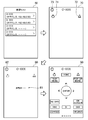
- the display control unit 52 causes the display unit 15 to display a device list screen 60 as shown in FIG.
- a device 20A A-XXX
- a device 20B B-XXX
- a device 20C C-XXX
- a device 20D D-XXX
- the device 20 that is currently in a power-on state or a network standby state can communicate according to TCP / IP and has an IP address assigned to a communication interface. Therefore, the IP address is displayed on the device list screen 60 for these devices 20.
- the device list screen 60 shown in FIG. 5 displays the IP addresses of the devices 20A and 20B, indicating that the devices 20A and 20B are currently in a power-on state or a network standby state.
- the device 20 currently in the WOL standby state cannot communicate in accordance with TCP / IP, and the IP address is not assigned to the communication interface. For this reason, IP addresses are not displayed on the device list screen 60 for these devices 20. In the device list screen 60 shown in FIG. 5, the IP addresses of the devices 20C and 20D are not displayed, indicating that the devices 20C and 20D are currently in the WOL standby state.
- the selection operation receiving unit 53 receives a selection operation for selecting the device 20 displayed on the display unit 15 as a control target. For example, the selection operation receiving unit 53 receives a selection operation for selecting any device 20 displayed on the device list screen 60 as a control target.
- the user selects one of the devices 20 displayed on the device list screen 60 as a control target (device to be operated) by bringing a finger or a touch pen into contact with the touch panel.
- the selection operation reception unit 53 receives the selection operation and specifies the device 20 selected as a control target by the user.
- the state control unit 54 shifts the device 20 specified by the device specifying unit 51 from the WOL standby state to the power-on state. For example, when the device 20 currently in the WOL standby state specified by the specifying unit 53 is selected as a control target, the state control unit 54 shifts the device 20 from the WOL standby state to the power-on state.
- a start instruction screen 70 as shown in FIG. 5 is displayed.
- the activation instruction screen 70 is a screen for shifting the device 20 in the WOL standby state to the power-on state.
- the activation instruction screen illustrated in FIG. 5 assumes a case where the device 20C in the WOL standby state is selected as a control target.
- the case where the device 20C is selected as a control target will be described.
- the start instruction screen 70 includes a power button 71 and an open button 72.
- the power button 71 is a button for instructing to shift the device 20 to the power-on state.
- the open button 72 is displayed when a device 20 having a disc tray, such as a Blu-ray disc player, is selected as a control target.
- the open button 72 is a button for instructing to open the disc tray while shifting the device 20 to the power-on state.
- the activation instruction screen 70 also includes a return button 73.
- the return button 73 is a button for returning to the previous screen (device list screen 60).
- a startup screen 80 as shown in FIG. 5
- a message 81 (or an image) indicating that the device 20C is being activated, that is, the device 20C is being shifted to the power-on state, is displayed on the activation screen 80.
- the start screen 80 also includes a return button 82 for returning to the previous screen (start instruction screen 70).
- the state control unit 54 transmits the magic packet (an example of “predetermined data” and “first predetermined data”) to the device 20C, thereby setting the device 20C to a WOL standby. Transition from state to power-on state.
- the magic packet is transmitted by communication in layer 2.
- the magic packet is transmitted (generated) based on the cache data stored in the cache data storage unit 50. That is, information necessary for transmitting the magic packet to the device 20C is stored in the cache data and is acquired from the cache data. For example, in order to transmit a magic packet to the device 20C, the MAC address of the device 20C is required. In this regard, the MAC address of the device 20C is stored in the cache data and is acquired from the cache data.
- the state control unit 54 determines whether or not the device 20C includes a wired communication interface unit (wired communication function) based on the cache data stored in the cache data storage unit 50.
- the state control unit 54 acquires the MAC address of the wired communication interface unit of the device 20C from the cache data. And the state control part 54 produces
- the state control unit 54 determines whether or not the device 20C includes a wireless communication interface unit (wireless communication function) based on the cache data stored in the cache data storage unit 50.
- the state control unit 54 acquires the MAC address of the wireless interface unit of the device 20C from the cache data. And the state control part 54 produces
- the state control unit 54 transmits a magic packet to each of the wired communication interface unit and the wireless communication interface unit of the device 20C. .
- the wired communication interface unit determines whether or not the MAC address included in the magic packet is its own MAC address.
- the MAC address included in the magic packet is its own MAC address
- a signal for shifting the device 20C to the power-on state is supplied to the device 20C through the wired communication interface, and as a result, the device 20C receives the WOL. Transition from standby state to power-on state.
- the MAC address included in the magic packet is not its own MAC address, the magic packet is ignored and the device 20C maintains the WOL standby state.
- the device 20C when the device 20C includes both the wired communication interface unit and the wireless communication interface unit, a magic packet is transmitted to each of these communication interface units. In this case, among the communication interface units, the device 20C is shifted to the power-on state by the communication interface unit that has received the magic packet first.
- the state determination unit 105 determines whether or not the device 20C has normally shifted to the power-on state after the magic packet is transmitted to the device 20C.
- the state determination unit 55 transmits a predetermined request for requesting a response reply to each device connected to the network, and receives a response returned from each device 20. Specifically, the state determination unit 55 transmits to the network an IP broadcast packet (an example of “predetermined request”) for inquiring about the existence of a UPnP-compatible device on the network, called M-SEARCH defined by the UPnP standard. Then, a response returned from each device 20 in response to the IP broadcast packet is received. The IP broadcast packet and the response from each device 20 are transmitted and received by communication at layer 3 or higher.
- IP broadcast packet an example of “predetermined request”
- the state determination part 55 determines whether the response from the apparatus 20C was received.
- responses are returned from all UPnP compatible devices connected to the network. Since the response in this case includes the device unique information as illustrated in FIG. 2, the state determination unit 55 includes the UUID indicated by the device unique information included in the received response and the device 20C registered in the cache data. It is determined whether or not the response is a response from the device 20C.
- the UPnP function uses the TCP / IP protocol as a communication protocol.
- the device 20C in the WOL standby state cannot perform communication conforming to the TCP / IP protocol.
- the device 20C can perform communication conforming to the TCP / IP protocol. . Therefore, reception of a response from the device 20C indicates that the device 20C has finished shifting to the power-on state. Therefore, when the response from the device 20C is received, the state determination unit 55 determines that the device 20C has shifted to the power-on state. On the other hand, when the response from the device 20C is not received, the state determination unit 55 determines that the device 20C has not shifted to the power-on state.
- an operation screen 90 as shown in FIG. 5 is displayed on the display unit 15.
- the operation screen 90 is a screen for the user to operate the device 20C. For this reason, the user can operate the device 20 ⁇ / b> C via the operation screen 90.
- the operation screen 90 shown in FIG. 5 assumes that the device 20C is a Blu-ray disc player.
- the operation screen 90 is set by imitating the remote control of the device 20C.
- the display content of the operation screen 90 is set according to the device 20 to be operated (controlled).
- the state control unit 54 transmits the predetermined data (an example of “second predetermined data”) to the device 20 by communication according to the TCP / IP protocol, thereby bringing the device 20 out of the network standby state. Transition to the power-on state.
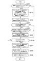
- FIG. 6 is a flowchart showing an example of the processing.
- the control unit 11 executes the process shown in FIG. 6 according to the program stored in the storage unit 12, the device specifying unit 51 and the display control unit 52 are realized.
- the control unit 11 determines whether or not the cache data of the device list exists (S100). That is, the control unit 11 determines whether or not the cache data as illustrated in FIG. 4 is stored in the storage unit 12.
- control unit 11 When the cache data exists, the control unit 11 confirms the existence of each device 20 registered in the cache data, and registers the device 20 that has been confirmed to exist in the detected device list (S101). ).
- the control unit 11 reads the IP address of the device 20 registered in the cache data from the cache data, and transmits an echo request to the device 20 by executing a Ping command on the IP address of the device 20. It is determined whether or not a response is returned from the device 20. When a response is returned from the device 20, the control unit 11 determines that the presence of the device 20 has been confirmed, and registers the device 20 in the detected device list. On the other hand, if no response is returned from the device 20, the control unit 11 determines that the presence of the device 20 has not been confirmed, and does not register the device 20 in the detected device list.
- the detected device list has the same data configuration as the device list (see FIG. 4) stored as cache data, for example.
- the device 20 whose presence can be confirmed in step S101 is the device 20 registered in the cache data (that is, the device 20 that has communicated with the control device 10 in the past), and is currently in the power-on state or the network standby.
- the device 20 that is in the state and to which the same IP address as the IP address registered in the cache data (that is, the IP address when communicating with the control device 10 in the past) is currently assigned. For this reason, when the step S101 is completed, such a device 20 is registered in the detected device list.
- the control unit 11 After execution of step S101 or when it is determined in step S100 that the cache data does not exist, the control unit 11 makes an inquiry about the existence of the device 20 to the network (S102). Specifically, the control unit 11 transmits an IP broadcast packet (M-SEARCH) for inquiring about the existence of a UPnP-compatible device on the network defined by the UPnP standard to the network. The UPnP-compatible device that has received the packet (M-SEARCH) returns a response to the control device 10. Therefore, the control unit 11 monitors whether or not a response from any of the devices 20 has been received (S103).
- M-SEARCH IP broadcast packet
- the control unit 11 determines whether or not the device 20 is already registered in the detected device list (S104). This determination is performed by comparing the UUID indicated by the device unique information included in the response from the device 20 with the UUID of each device 20 registered in the detected device list. When the UUID indicated by the device specific information included in the response does not match the UUID of any device 20 registered in the detected device list, the control unit 11 indicates that the device 20 is not registered in the detected device list. judge.
- the control unit 11 When the device 20 is not registered in the detected device list, the control unit 11 registers the device 20 in the detected device list (S105). Thereafter, the control unit 11 determines whether or not the standby timeout time has elapsed (S106). In other words, the control unit 11 determines whether or not the elapsed time since the execution of step S102 has reached the standby timeout time. Even when it is determined in step S104 that the device 20 has already been registered in the detected device list, or when it is determined in step S103 that no response has been received from any device 20, The control unit 11 determines whether or not the standby timeout time has elapsed (S106).
- the control unit 11 continues to monitor whether or not a response from any of the devices 20 has been received (S103). On the other hand, when the standby time-out time has elapsed, the control unit 11 stops waiting for a response from the device 20.
- the device 20 that is currently in the power-on state or the network standby state but could not be confirmed in step S101 is additionally registered in the detected device list.
- a device 20 that has not been registered in the cache data that is, a device 20 that has not communicated with the control device 10 in the past
- is currently in a power-on state or a network standby state
- the device 20 that is registered in the cache data and is currently in the power-on state or the network standby state, but is currently assigned an IP address different from the IP address registered in the cache data is detected. Added to the list of used devices.
- FIG. 7 is a flowchart showing an example of the process of step S107.
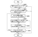
- control unit 11 first determines whether or not the cache data of the device list exists (S200). This process is the same as step S101 in FIG.
- the control unit 11 determines whether or not a WOL compatible device is registered in the cache data (S201). Whether or not the device 20 registered in the cache data is a WOL compatible device is determined by referring to the item “yamaha: X_magicPacketWakeSupported” of the terminal specific information (see FIG. 2) included in the cache data. Can do.
- the control unit 11 acquires information on the WOL compatible device from the cache data (S202). Then, the control unit 11 determines whether or not the WOL-compatible device is already registered in the detected device list (S203). This determination is performed by comparing the UUID registered in the information acquired in step S202 with the UUID of each device 20 registered in the detected device list. When the UUID registered in the information acquired in step S202 does not match the UUID of any device 20 registered in the detected device list, the control unit 11 registers the WOL-compatible device in the detected device list. Judge that it is not. When the WOL compatible device is not registered in the detected device list, the control unit 11 registers the WOL compatible device in the detected device list (S204).
- step S204 After execution of step S204, or when it is determined in step S203 that the WOL compatible device is registered in the detected device list, the control unit 11 determines whether another WOL compatible device is registered in the cache data. Is determined (S205). When another WOL compatible device is registered in the cache data, the control unit 11 acquires information on the WOL compatible device from the cache data (S202), and executes the processes of steps S203 to S205 again. On the other hand, if no other WOL-compatible device is registered in the cache data, the control unit 11 ends this processing and executes step S108 in FIG.
- the control unit 11 updates the cache data based on the detected device list (S108). For example, when there is a device 20 not registered in the cache data among the devices 20 registered in the detected device list, the control unit 11 adds information on the device 20 to the cache data. Further, for example, when the IP address of the device 20 registered in the detected device list is different from the IP address of the device 20 registered in the cache data, the control unit 11 performs the same operation registered in the cache data. The IP address of the device 20 is replaced with the IP address of the device 20 registered in the detected device list.
- control unit 11 After execution of step S108, the control unit 11 displays the device list screen 60 on the display unit 15 (S109). In this case, the control unit 11 displays a list of devices 20 registered in the detected device list on the device list screen 60.
- FIGS. 8A and 8B are flowcharts showing an example of the processing.
- the control unit 11 executes the processes shown in FIGS. 8A and 8B according to the program stored in the storage unit 12, the state control unit 54 and the state determination unit 55 are realized.
- the power button 71 is selected to shift the device 20C to the power-on state. 8A and 8B will be described on the assumption that the above-described process is performed.
- the control unit 11 displays a startup screen 80 on the display unit 15 (S300). Thereafter, the control unit 11 sets an overall timeout time (S301).
- the “total timeout period” is the timeout period for the entire process.
- the total timeout time is set to a time longer than a standby timeout time in step S312 described later. For example, the total timeout time is set to a time longer than three times the standby timeout time in step S312 described later. The significance of setting the overall timeout time in this way will be described later.
- the control unit 11 determines whether or not the MAC address of the wired communication interface unit of the device 20C is registered in the cache data (S302). That is, the control unit 11 determines whether or not the device 20C includes a wired communication interface unit. This determination can be made by referring to the item “yamaha: X_macAddressWired” of the terminal specific information included in the cache data.
- the control unit 11 transmits a magic packet specifying the MAC address of the wired communication interface unit of the device 20C (S303). That is, the control unit 11 sets the destination address to “FF: FF: FF: FF: FF: FF” (layer 2 broadcast address), and the MAC address of the wired communication interface unit of the device 20C is repeated 16 times. Send a magic packet.
- step S303 After execution of step S303 or when it is determined in step S302 that the MAC address of the wired communication interface unit of the device 20C is not registered in the cache data, the control unit 11 determines that the MAC address of the wireless communication interface unit of the device 20C is It is determined whether or not it is registered in the cache data (S304). That is, the control unit 11 determines whether the device 20C includes a wireless communication interface unit. This determination can be made by referring to the item “yamaha: X_macAddressWireless” of the terminal specific information included in the cache data.
- the control unit 11 transmits a magic packet specifying the MAC address of the wireless communication interface unit of the device 20C. (S303). That is, the control unit 11 sets the destination address to “FF: FF: FF: FF: FF: FF” (layer 2 broadcast address), and the MAC address of the wireless communication interface unit of the device 20C is repeated 16 times. Send a magic packet.
- step S305 After executing step S305, or when it is determined in step S304 that the MAC address of the wireless communication interface unit of the device 20C is not registered in the cache data, the control unit 11 has successfully shifted the device 20C to the power-on state. Check whether or not. Specifically, as shown in FIG. 8B, the control unit 11 makes an inquiry about the presence of the device 20 to the network (S306), and then monitors whether a response from any of the devices 20 has been received. (S307). The processes in steps S306 and S307 are the same as steps S102 and S103 in FIG.
- the control unit 11 determines whether or not the response is a response from the device 20C (magic packet transmission destination device 20) (S308). This determination is performed by comparing the UUID indicated by the device unique information included in the response with the UUID indicated by the device unique information of the device 20C included in the cache data. When the UUID indicated by the device unique information included in the response matches the UUID indicated by the device unique information of the device 20C included in the cache data, the control unit 11 determines that the response is a response from the device 20C.
- the case where the response is determined to be a response from the device 20C is a case where the device 20C can communicate according to the TCP / IP protocol. This is a case where the normal transition from the standby state to the power-on state has been completed.
- the control unit 11 updates the detected device list (S309).
- the control unit 11 also updates the cache data of the device list (S310). For example, the control unit 11 registers the IP address information of the device 20C in the detected device list and cache data. After executing steps S309 and S310, the control unit 11 displays the operation screen 90 of the device 20C on the display unit 15 (S311).
- step S307 If it is determined in step S307 that no response has been received from any device 20, or if it is determined in step S308 that the received response is not a response from the device 20C, the control unit 11 waits for a standby timeout. It is determined whether or not elapses (S312). In other words, the control unit 11 determines whether or not the elapsed time after executing step S306 is equal to or longer than the standby timeout time.
- the control unit 11 continues to monitor whether or not a response from any of the devices 20 has been received (S307). On the other hand, when the standby timeout time has elapsed, the control unit 11 stops waiting for a response from the device 20, and determines whether or not the overall timeout time has elapsed (S313). That is, the control unit 11 determines whether or not the elapsed time since the execution of this process has started is equal to or greater than the overall timeout time. If the entire timeout time has not elapsed, the control unit 11 makes an inquiry about the presence of the device 20 to the network again (S306).
- the processing in steps S306 to S308 (the device 20C normally shifts to the power-on state before the overall timeout time elapses).
- the process of confirming whether or not the process has been completed is executed a plurality of times. For example, by setting the overall timeout time to a time longer than three times the standby timeout time, the processes in steps S306 to S308 are executed a maximum of three times.
- the control device 10 executes the processes in steps S306 to S308 a plurality of times, so that such inconvenience is less likely to occur. .
- the case where it is determined in step 313 that the total timeout time has elapsed is a case where it has not been possible to confirm that the device 20C has successfully shifted to the power-on state before the total timeout time has elapsed.
- the control unit 11 determines that the device 20C has not shifted to the power-on state, and displays the activation instruction screen 70 on the display unit 15 (S314). At this time, the control unit 11 displays an error message indicating that the device 20 ⁇ / b> C could not be shifted to the power-on state on the activation instruction screen 70.
- the user can operate the devices 20A to 20D using the control device 10.
- the control device 10 even if the device 20 (WOL-compatible device) is in the WOL standby state, the user can shift the device 20 to the power-on state and start operating the device 20.
- the control device 10 since the device 20 is shifted from the WOL standby state to the power-on state based on the information (MAC address or the like) of the device 20 stored as cache data, the user can change the MAC address of the device 20. There is no need to check in advance or input the MAC address to the control device 10. For this reason, according to the control device 10, the user can easily shift the device 20 in the WOL standby state to the power-on state. In other words, it is possible to reduce the user's effort to shift the device 20 in the WOL standby state to the power-on state.
- the device 20 in the WOL standby state is identified and displayed on the device list screen 60.
- the device 20 in the WOL standby state is not in a state in which communication according to the IP protocol (TCP / IP protocol) is possible, so the power-on state or the network standby state
- the device 20 in the WOL standby state cannot be specified by a method similar to the method for specifying the device 20 in the WOL standby state.
- the device 20 in the WOL standby state is identified and displayed on the device list screen 60 based on the information of the device 20 stored as cache data. As a result, the user can grasp that there is a device 20 in the WOL standby state.
- the control device 10 when the device 20 in the WOL standby state includes both the wired communication interface unit and the wireless communication interface unit, the control device 10 transmits a magic packet to each of the communication interface units. According to the control device 10, by doing so, it is difficult for the magic packet to reach the device 20, and as a result, the device 20 in the WOL standby state is shifted to the power-on state. It becomes difficult to fail.
- control device 10 checks whether or not the device 20 has normally shifted to the power-on state after transmitting a magic packet to the device 20 in the WOL standby state (FIG. 8B). Steps S306 to S308). If the operation screen 90 is displayed when the device 20 is not in the power-on state, the device 20 will not operate as operated even if the user operates the operation screen 90. There is a risk of feeling. In this regard, according to the control device 10, it is possible to prevent the operation screen 90 from being displayed when the device 20 is not in the power-on state by performing the above-described confirmation.
- control device 10 even if a network standby compatible device and a WOL compatible device are mixed, the user can operate the device 20 without being particularly aware of the difference between them.
- the present invention is not limited to the embodiment described above.
- the activation instruction screen 70 may be omitted.
- the processing shown in FIGS. 8A and 8B may be executed when the device 20 in the WOL standby state is selected as the control target on the device list screen 60.
- the processing shown in FIGS. 8A and 8B is executed after the device 20 in the WOL standby state is selected as the control target.
- the device 20 is in the WOL standby state. You may make it perform the process shown to FIG. 8A and FIG. 8B before the apparatus 20 is selected as a control object.
- the processing shown in FIGS. 8A and 8B may be executed for the device 20 as a target. .
- both the network standby compatible device and the WOL compatible device are mixed in the device 20 controlled by the control device 10, but the device 20 controlled by the control device 10 includes A network standby device may not be included.
- the device 20 controlled by the control device 10 may be only a WOL compatible device.
- the device 20 may not be an audio device or an audiovisual device. Moreover, the some apparatus 20 controlled by the control apparatus 10 does not need to be the same kind of apparatus. The plurality of devices 20 controlled by the control device 10 may include different types of devices.
- the network between the control device 10 and the device 20 does not need to include both the wired LAN 30 and the wireless LAN, and may include only one of them.
- the present invention can be applied to cases other than such a case. . That is, the present invention can also be applied to devices other than WOL compatible devices.
- the present invention describes a device from a “restricted state in which control of the device by the first type communication is restricted by restricting the communication possible by the device to the second type of communication” from the “first type. It is possible to apply to the case of shifting to a “controllable state in which the device can be controlled by communication”.
- 1 device control system 10 control device, 11 control unit, 12 storage unit, 13 communication unit, 14 operation unit, 15 display unit, 20A, 20B, 20C, 20D device, 30 wired LAN, 32 wireless LAN access point, 40th 1 part, 41 2nd part, 50 cache data storage part, 51 device identification part, 52 display control part, 53 selection operation reception part, 54 state control part, 55 state determination part, 60 equipment list screen, 70 start instruction screen, 71 power button, 72 open button, 73 return button, 80 startup screen, 81 message, 82 return button, 90 operation screen.
Landscapes
- Engineering & Computer Science (AREA)
- Automation & Control Theory (AREA)
- Computer Networks & Wireless Communication (AREA)
- Signal Processing (AREA)
- Theoretical Computer Science (AREA)
- Computer Security & Cryptography (AREA)
- Physics & Mathematics (AREA)
- General Engineering & Computer Science (AREA)
- General Physics & Mathematics (AREA)
- Small-Scale Networks (AREA)
Abstract
機器特定部(51)は、過去に制御可能状態(第1種の通信により当該機器を制御することが可能な状態)であった機器に関する機器情報に基づき、当該機器情報に含まれる機器を特定する。状態制御部(54)は、機器特定部(51)によって特定された機器に対し、第2種の通信によって所定データを送信することによって、当該機器を制限状態(当該機器が可能な通信が第2種の通信に制限され、第1種の通信により当該機器を制御することが制限される状態)から制御可能状態に移行させる。
Description
本発明は機器制御方法、プログラム、制御装置、及び機器制御システムに関する。
ネットワークスタンバイ機能を備えたネットワークスタンバイ対応機器や、Wake-On-LAN機能を備えたWOL対応機器が知られている。ネットワークスタンバイ対応機器では、TCP/IPプロトコルに則った通信機能を保持しつつ、機器の消費電力が軽減されたスタンバイ状態となる。このようなネットワークスタンバイ対応機器では、スタンバイ状態においても上記通信機能が保持されるため、機器をスタンバイ状態から通常の電源オン状態へと移行させるのが容易である反面、スタンバイ状態でも上記通信機能が保持されることによって機器の消費電力を軽減するという点で十分でない場合がある。一方、WOL対応機器のスタンバイ状態では、TCP/IPプロトコルに則った通信機能も制限されるため、ネットワークスタンバイ対応機器のスタンバイ状態よりも機器の消費電力が軽減される。
しかしながら、WOL対応機器をスタンバイ状態から通常の電源オン状態に移行させるためには、マジックパケットと呼ばれる、WOL対応機器の通信インタフェース部のMACアドレスが指定された所定のパケットを送信する必要がある。このため、WOL対応機器をスタンバイ状態から電源オン状態に移行させるために、ユーザはWOL対応機器の通信インタフェース部のMACアドレスを事前に調べたり、当該MACアドレスを入力したりする必要がある。この点、ネットワーク技術に十分に精通していないユーザにとって、WOL対応機器の通信インタフェース部のMACアドレスを調べることは困難である場合があった。また、ネットワーク技術に精通しているユーザにとっても、WOL対応機器の通信インタフェース部のMACアドレスを事前に調べたり、当該MACアドレスを入力したりする手順を行うことは煩雑である場合があった。
本発明は上記課題に鑑みてなされたものであって、その目的は、例えば、WOL対応機器をスタンバイ状態から通常の電源オン状態に容易に移行させることが可能な機器制御方法、プログラム、制御装置、及び機器制御システムを提供することにある。
上記課題を解決するために、本発明に係る機器制御方法は、ネットワークを介して機器を制御する機器制御方法において、前記機器は、前記ネットワークを介した第1種の通信により当該機器を制御することが可能な制御可能状態と、当該機器によって可能な通信が第2種の通信に制限され、前記第1種の通信により当該機器を制御することが制限される制限状態と、になり得るものであり、前記機器制御方法は、記憶手段に記憶された過去に前記制御可能状態であった機器に関する機器情報に基づき、前記機器情報に含まれる機器を特定する特定ステップと、前記特定ステップによって特定された機器に対し、前記第2種の通信によって前記機器情報に基づく所定データを送信することによって、当該機器を前記制限状態から前記制御可能状態に移行させる状態制御ステップと、を含む。
また、本発明に係るプログラムは、ネットワークを介して機器を制御する制御装置としてコンピュータを機能させるためのプログラムにおいて、前記機器は、前記ネットワークを介した第1種の通信により当該機器を制御することが可能な制御可能状態と、当該機器によって可能な通信が第2種の通信に制限され、前記第1種の通信により当該機器を制御することが制限される制限状態と、になり得るものであり、前記プログラムは、記憶手段に記憶された過去に前記制御可能状態であった機器に関する機器情報に基づき、前記機器情報に含まれる機器を特定する特定手段、及び、前記特定手段によって特定された機器に対し、前記第2種の通信によって前記機器情報に基づく所定データを送信することによって、当該機器を前記制限状態から前記制御可能状態に移行させる状態制御手段、として前記コンピュータを機能させるプログラムである。
また、本発明に係る情報記憶媒体は、上記プログラムを記録したコンピュータ読み取り可能な情報記憶媒体である。
また、本発明に係る制御装置は、ネットワークを介して機器を制御する制御装置において、前記機器は、前記ネットワークを介した第1種の通信により当該機器を制御することが可能な制御可能状態と、当該機器によって可能な通信が第2種の通信に制限され、前記第1種の通信により当該機器を制御することが制限される制限状態と、になり得るものであり、前記制御装置は、記憶手段に記憶された過去に前記制御可能状態であった機器に関する機器情報に基づき、前記機器情報に含まれる機器を特定する特定手段と、前記特定手段によって特定された機器に対し、前記第2種の通信によって前記機器情報に基づく所定データを送信することによって、当該機器を前記制限状態から前記制御可能状態に移行させる状態制御手段と、を含む。
また、本発明に係る機器制御システムは、機器と、ネットワークを介して前記機器を制御する制御装置とを含む機器制御システムにおいて、前記機器は、前記ネットワークを介した第1種の通信により当該機器を制御することが可能な制御可能状態と、当該機器によって可能な通信が第2種の通信に制限され、前記第1種の通信により当該機器を制御することが制限される制限状態と、になり得るものであり、前記制御装置は、記憶手段に記憶された過去に前記制御可能状態であった機器に関する機器情報に基づき、前記機器情報に含まれる機器を特定する特定手段と、前記特定手段によって特定された機器に対し、前記第2種の通信によって前記機器情報に基づく所定データを送信することによって、当該機器を前記制限状態から前記制御可能状態に移行させる状態制御手段と、を含む。
また、本発明の一態様では、前記特定ステップは、前記機器情報に含まれる各機器に対し、前記第1種の通信によって所定要求を送信し、当該所定要求に応じて当該各機器から前記第1種の通信によって返信される応答を受信することによって、前記制御可能状態にある機器を特定するステップと、前記制御可能状態にある機器の特定結果と、前記記憶手段に記憶された機器情報と、に基づき、前記機器情報に含まれる機器のうちの、前記制限状態にある機器を特定するステップと、を含むようにしてもよい。
また、本発明の一態様では、前記特定ステップは、前記ネットワークに接続される各機器に対し、前記第1種の通信によって所定要求を送信し、当該所定要求に応じて当該各機器から前記第1種の通信によって返信される応答を受信することによって、前記制御可能状態にある機器を特定するステップと、前記制御可能状態にある機器の特定結果と、前記記憶手段に記憶された機器情報と、に基づき、前記機器情報に含まれる機器のうちの、前記制限状態にある機器を特定するステップと、を含むようにしてもよい。
また、本発明の一態様では、前記記憶手段に記憶された機器情報に基づき、前記特定ステップによって特定された機器に関する情報を表示手段に表示させる表示制御ステップと、前記表示手段に表示される機器を制御対象として選択する選択操作を受け付ける選択操作受付ステップと、を含み、前記状態制御ステップでは、前記特定ステップによって特定された機器が前記制御対象として選択された場合に、当該機器に対し、前記第2種の通信によって前記所定データを送信するようにしてもよい。
また、本発明の一態様では、前記機器制御方法は、前記ネットワークを介して第1機器と第2機器とを制御する方法であり、前記第1機器は、前記制御可能状態と、当該機器への電力供給が制限されることにより、当該機器によって可能な通信が前記第2種の通信に制限され、前記第1種の通信により当該機器を制御することが制限される第1制限状態と、になり得るものであり、前記第2機器は、前記制御可能状態と、当該機器への電力供給が制限されるが、前記第1種の通信により当該機器を制御することが可能な第2制限状態と、になり得るものであり、前記特定ステップは、前記機器情報に含まれる各機器と、前記ネットワークに接続される各機器と、の少なくとも一方に対し、前記第1種の通信によって所定要求を送信し、当該所定要求に応じて当該各機器から前記第1種の通信によって返信される応答を受信することによって、前記制御可能状態にある前記第1機器と、前記制御可能状態又は前記第2制限状態にある前記第2機器と、のリストを取得するステップと、過去に前記制御可能状態であった機器であって、かつ、前記リストに含まれていない機器を特定することによって、前記第1制限状態にある前記第1機器を特定するステップと、を含み、前記表示制御ステップでは、前記制御可能状態にある前記第1機器に関する情報と、前記制御可能状態又は前記第2制限状態にある前記第2機器に関する情報と、前記第1制限状態にある前記第1機器に関する情報と、を前記表示手段に表示させ、前記状態制御ステップは、前記第2制限状態にある前記第2機器が前記制御対象として選択された場合に、当該第2機器に対し、前記第1種の通信によって第2所定データを送信することによって、当該第2機器を前記第2制限状態から前記制御可能状態に移行させるステップと、前記第1制限状態にある前記第1機器が前記制御対象として選択された場合に、当該第1機器に対し、前記第2種の通信によって前記機器情報に基づく第1所定データを送信することによって、当該第1機器を前記第1制限状態から前記制御可能状態に移行させるステップと、を含むようにしてもよい。
また、本発明の一態様では、前記機器は、有線ネットワークを介して前記第1種の通信及び前記第2種の通信を行うことが可能な有線通信機能と、無線ネットワークを介して前記第1種の通信及び前記第2種の通信を行うことが可能な無線通信機能と、の少なくとも一方を備え、前記記憶手段に記憶される機器情報は、過去に前記制御可能状態であった機器が前記有線通信機能を備えている否かの情報と、過去に前記制御可能状態であった機器が前記無線通信機能を備えている否かの情報と、を含み、前記状態制御ステップでは、前記特定ステップによって特定された機器が前記有線通信機能と前記無線通信機能との両方を備えている場合、当該機器に対し、前記有線通信機能を用いた前記第2種の通信と、前記無線通信機能を用いた前記第2種の通信と、の各々によって前記所定データを送信するようにしてもよい。
また、本発明の一態様では、前記状態制御ステップによって、前記特定ステップによって特定された機器に対して前記第2種の通信によって前記所定データが送信された後において、前記ネットワークに接続される各機器に対し、前記第1種の通信によって所定要求を送信し、当該所定要求に応じて当該各機器から前記第1種の通信によって返信される応答を受信するステップと、前記特定ステップによって特定された機器から前記応答が受信されたか否かを判定することによって、当該機器が前記制御可能状態に移行したか否かを判定する状態判定ステップと、を含むようにしてもよい。
また、本発明の一態様では、前記制御可能状態は、前記第1種の通信により、当該機器に関する情報を当該機器から取得することと、当該機器を制御することとが可能な状態であり、前記制限状態は、前記機器への電力供給が制限されることにより、当該機器によって可能な通信が前記第2種の通信に制限され、前記第1種の通信によって、当該機器に関する情報を当該機器から取得することと、当該機器を制御することとが制限される状態であってもよい。
本発明によれば、例えば、WOL対応機器をスタンバイ状態から通常の電源オン状態に容易に移行させることが可能になる。
以下、本発明の実施形態について図面を参照しながら説明する。図面では同一又は同等の要素に同一の符号を付し、重複する説明を省略する。
図1は、本発明の実施形態に係る制御装置10を含む機器制御システム1の構成の一例を示す。図1に示すように、機器制御システム1は制御装置10と機器20A,20B,20C,20Dとを含む。図1に示す例では、4台の機器20A~20Dが含まれているが、3台以下の機器が含まれていてもよいし、5台以上の機器が含まれていてもよい。
制御装置10はネットワークを介して機器20A~20Dを制御するためのものであり、ユーザが機器20A~20Dを操作するために用いられる。制御装置10は、例えば、スマートフォン、タブレット型コンピュータ、ラップトップ型コンピュータ、又はデスクトップ型コンピュータ等によって実現される。ただし、制御装置10は、このような汎用装置を用いて実現されなくてもよく、専用装置として実現されてもよい。
図1に示すように、制御装置10は制御部11、記憶部12、通信部13、操作部14、及び表示部15を含む。制御部11は1又は複数のマイクロプロセッサを含み、記憶部12に記憶されたプログラムに従って処理を実行する。記憶部12は、例えば主記憶(RAM等)及び補助記憶(ハードディスクドライブ又はソリッドステートドライブ等)の情報記憶媒体を含み、制御部11によって実行されるプログラムを記憶する。記憶部12は制御部11のワークメモリとしても動作する。
例えば、プログラム又はデータはネットワークを介して制御装置10に提供される。なお、制御装置10は、例えばメモリカード又は光ディスク等のコンピュータで読み取り可能な情報記憶媒体に記憶されたプログラム又はデータを読み出すための構成要素を含むようにしてもよい。そして、プログラム又はデータが情報記憶媒体を介して制御装置10に提供されるようにしてもよい。すなわち、後述の図6,7,8A,8Bに示す処理を実行するためのプログラムはネットワークを介して提供されるようにしてもよいし、情報記憶媒体に記憶されて提供されるようにしてもよい。
通信部13は他の装置とネットワークを介してデータ通信するためのものである。例えば、通信部13は、無線LANを介して通信を行うための無線通信インタフェース部を含んでおり、図1に示すように、制御装置10は、有線LAN30と接続された無線LANアクセスポイント32と無線通信を行うことが可能であり、無線LANアクセスポイント32及び有線LAN30を介して機器20A~20Dと通信を行うことが可能である。なお、通信部13は、有線LANを介して通信を行うための有線通信インタフェース部を含むようにしてもよい。
操作部14はユーザが各種操作を行うためのものである。表示部15は、例えば液晶ディスプレイ又は有機ELディスプレイ等であり、制御部11からの指示に従い画面を表示する。なお、図1では操作部14と表示部15とが別個に示されているが、操作部14と表示部15とはいわゆるタッチパネルとして一体的に構成されてもよい。この場合、ユーザは指又はタッチペン等でタッチパネルに接触することによって各種操作を行うことが可能である。タッチパネルとしては、例えば、タッチされた部分の容量変化を検出する静電容量結合方式、抵抗値変化を検出する抵抗膜方式、又はタッチにより遮蔽された部分の光量変化を検出する光センサ方式等の各種方式のタッチパネルを用いることが可能である。
以下では、タッチパネルを備えたスマートフォン又はタブレット型コンピュータによって制御装置10が実現される場合を主に想定する。ただし、操作部14と表示部15とをタッチパネルとして一体的に構成することは必須ではなく、操作部14は、例えばボタン、キー、レバー(スティック)、マウス、又はトラックパッド等のような表示部15と別個に設けられる操作子であってもよい。
機器20A~20Dは、制御装置10による制御の対象となる機器である。言い換えれば、機器20A~20Dは、ユーザが制御装置10を用いて操作する対象となる機器である。例えば、機器20A~20Dはオーディオ機器又はオーディオビジュアル機器である。具体的には、機器20A~20Dはブルーレイディスクプレーヤやアンプ等であり、制御装置10はコンテンツの再生指示や音量調整等の操作を行うために用いられる。以下では、機器20A~20Dがオーディオ機器又はオーディオビジュアル機器である場合を想定して説明するが、機器20A~20Dはオーディオ機器又はオーディオビジュアル機器に限られず、他の用途の機器であってもよい。
機器20A~20Dの各々は有線通信インタフェース部と無線通信インタフェース部との少なくとも一方を備える。図1に示す例では、機器20A~20Cは有線通信インタフェース部を備えており、機器20A~20Cは有線LAN30に接続されている。また、機器20C,20Dは無線通信インタフェース部を備えており、機器20C,20Dは無線LANアクセスポイント32と無線通信を行うことが可能になっている。機器20A~20Dの各々は、IPプロトコル(TCP/IPプロトコル)に則った通信を行うことが可能である。
また、機器20A~20Dは、UPnP(Universal Plug and Play)機能を備えたUPnP対応機器である。UPnP機能を備えることによって、機器20A~20Dは、ネットワークに接続されると、複雑な設定を要することなく、他の装置と通信することが可能になる。また、機器20A~20DがUPnP機能を備えていることにより、制御装置10から機器20A~20Dの存在を確認したり、機器20A~20Dの情報(例えば機器20Aの状態や機能等)を取得したり、機器20A~20Dを操作したり、機器20A~20Dの機能を利用したりすることが可能になる。
例えば、制御装置10が、UPnP規格で規定された、ネットワーク上のUPnP対応機器の存在を問い合わせるためのIPブロードキャストパケット(M-SEARCH)をネットワーク(有線LAN30及び無線LAN)に対して送信すると、UPnP対応機器である機器20A~20Dの各々から応答が制御装置10に返信される。この場合、例えば、機器固有の情報を示す機器固有情報が上記応答として制御装置10に返信される。
図2は機器固有情報の一例を示す。図2は、機器20Cから制御装置10に返信される機器固有情報の一例を示す。図2に示すように、機器固有情報は、機器20Cのモデル名や製造元等の情報をXML形式で示す。機器固有情報は第1部分40と第2部分41とを含む。第1部分40は、UPnP規格で予め定められた項目を示し、第2部分41は、UPnP規格に則って機器20Cの製造元によって追加された項目を示す。なお、第1部分40内の項目「modelName」はモデル名を示し、項目「UDN」は、個々の機器を一意に識別する識別情報であるUUIDを示す。同じモデル名(C-XXX)の機器であっても、UUIDは個々の機器ごとに異なる。また、第2部分41内の項目「yamaha:X_macAddressWired」は有線通信インタフェース部のMACアドレスを示す。また、項目「yamaha:X_macAddressWireless」は無線通信インタフェース部のMACアドレスを示す。さらに、項目「yamaha:X_fwVersion」はファームウェアのバージョンを示し、項目「yamaha:X_destination」は仕向地域を示し、項目「yamaha:X_featureExistence」は機器の有する機能を示す。なお、項目「yamaha:X_magicPacketWakeSupported」に関しては後述する。
機器20A~20Dには、Wake-On-LAN機能を備えたWOL対応機器(「第1機器」の一例)と、ネットワークスタンバイ機能を備えたネットワークスタンバイ対応機器(「第2機器」の一例)とが含まれる。以下では、機器20A,20Bがネットワークスタンバイ対応機器であり、機器20C,20DがWOL対応機器であることとして説明する。
ネットワークスタンバイ対応機器は通常の電源オン状態(「制御可能状態」の一例)とスタンバイ状態(「第2制限状態」の一例)とになり得る。例えば、ネットワークスタンバイ対応機器は、一定時間にわたって使用されなかった場合に、消費電力を軽減すべく、電源オン状態からスタンバイ状態へと変化する。スタンバイ状態では、ネットワークスタンバイ対応機器への電力供給が制限され、電源オン状態と比べて機器全体の消費電力が軽減される。すなわち、スタンバイ状態では、通信機能以外の機能に関する電力供給が制限され、通信機能以外の機能の利用が制限されることによって、機器全体の消費電力が軽減される。
ネットワークスタンバイ対応機器におけるスタンバイ状態では、電源オン状態と同様に、IPプロトコルに則った通信(レイヤ3以上での通信)を行うことが可能である。すなわち、有線通信インタフェース部又は無線通信インタフェース部にIPアドレスが割り当てられた状態が維持され、IPネットワーク上に機器が存在していることになる。
ネットワークスタンバイ対応機器におけるスタンバイ状態ではUPnP機能も有効になっている。UPnP機能では通信プロトコルとしてTCP/IPプロトコルを利用するが、ネットワークスタンバイ対応機器では、電源オン状態とスタンバイ状態とのいずれにおいても、TCP/IPプロトコルに則った通信(「第1種の通信」の一例)を行うことが可能である。このため、電源オン状態とスタンバイ状態とのいずれにおいても、TCP/IPプロトコルに則った通信により、制御装置10からネットワークスタンバイ対応機器の存在を確認したり、ネットワークスタンバイ対応機器に関する情報を取得したり、ネットワークスタンバイ対応機器を制御したりすることが可能である。例えば、TCP/IPプロトコルに則った通信により、制御装置10からネットワークスタンバイ対応機器をスタンバイ状態から電源オン状態に移行させることができる。
一方、WOL対応機器も通常の電源オン状態(「制御可能状態」の一例)とスタンバイ状態(「制限状態」又は「第1制限状態」の一例)とをとる。スタンバイ状態では、通常の電源オン状態と比べて機器全体の消費電力が軽減される。しかしながら、ネットワークスタンバイ対応機器におけるスタンバイ状態とは異なり、WOL対応機器におけるスタンバイ状態では、通信機能も制限することによって、ネットワークスタンバイ対応機器におけるスタンバイ状態よりも消費電力が軽減される。
すなわち、ネットワークスタンバイ対応機器におけるスタンバイ状態と異なり、WOL対応機器におけるスタンバイ状態では、WOL対応機器への電力供給が制限され、IPプロトコルに則った通信(レイヤ3以上での通信)が制限される。すなわち、WOL対応機器におけるスタンバイ状態では、有線通信インタフェース部又は無線通信インタフェース部にIPアドレスが割り当てられておらず、IPネットワーク上に機器が存在していないことになる。このため、WOL対応機器におけるスタンバイ状態ではUPnP機能が無効になる。
WOL対応機器における電源オン状態では、TCP/IPプロトコルに則った通信を行うことが可能であるため、制御装置10からWOL対応機器の存在を確認したり、WOL対応機器に関する情報を取得したり、WOL対応機器を制御したりすることが可能である。これに対し、先述の通り、WOL対応機器におけるスタンバイ状態では、TCP/IPプロトコルに則った通信を行うことが可能でないため、TCP/IPプロトコルに則った通信によって、制御装置10からWOL対応機器の存在を確認したり、WOL対応機器に関する情報を取得したり、WOL対応機器を制御したりすることができない。
WOL対応機器におけるスタンバイ状態では、通信インタフェース部(有線通信インタフェース部又は無線通信インタフェース部)に最低限の電力が供給されており、レイヤ2での通信(「第2種の通信」の一例)は可能になっている。すなわち、通信インタフェースは自分のMACアドレス宛てのパケットを受信可能な状態になっており、自分のMACアドレスが指定されたマジックパケットと呼ばれる特定のパケットが通信インタフェースによって受信されると、WOL対応機器はスタンバイ状態から電源オン状態に移行する。なお、「マジックパケット」とは、宛先アドレスが「FF:FF:FF:FF:FF:FF」(レイヤ2のブロードキャストアドレス)に設定され、かつ、通信インタフェースのMACアドレスが16回繰り返されてなるパケットである。
図2に示した機器固有情報の第2部分41内の項目「yamaha:X_magicPacketWakeSupported」は、WOL対応機器であるか否かを示す。すなわち、上記項目は、マジックパケットによってスタンバイ状態から通常の電源オン状態に移行させることが可能であるか否かを示す。例えば、値「0」又は「1」が上記項目に設定される。値「0」はWOL対応機器でないことを示し、値「1」はWOL対応機器であることを示す。
上記の機器制御システム1では、ユーザは制御装置10を用いて機器20A~20Dを操作することができる。例えば、WOL対応機器である機器20Cがスタンバイ状態であったとしても、マジックパケットによって機器20Cをスタンバイ状態から電源オン状態に移行させ、ユーザは機器20Cの操作を開始することができる。しかしながら、従来、マジックパケットによってWOL対応機器をスタンバイ状態から電源オン状態に移行させるために、ユーザはWOL対応機器の通信インタフェースのMACアドレスを事前に調べておく必要があり、かつ、当該MACアドレスを入力する必要があった。この点、ネットワーク技術に十分に精通していないユーザにとって、通信インタフェースのMACアドレスを調べることは困難である場合があった。また、ネットワーク技術に精通しているユーザにとっても、通信インタフェースのMACアドレスを調べておいて、当該MACアドレスを入力する手順を行うことは煩雑である場合があった。
この点、上記の機器制御システム1(制御装置10)では、ユーザがスタンバイ状態にあるWOL対応機器の操作を容易に開始できるようになっている。以下、この点について詳細に説明する。なお以下では、ネットワークスタンバイ対応機器におけるスタンバイ状態と、WOL対応機器におけるスタンバイ状態とを区別すべく、便宜上、前者を「ネットワークスタンバイ状態」と記載し、後者を「WOLスタンバイ状態」と記載する。また以下では、機器20A~20Dを総称して「機器20」と記載する場合がある。
図3は、制御装置10で実現される機能のうち、本発明に関連するものを主に示す機能ブロック図である。図3に示すように、制御装置10は、キャッシュデータ記憶部50、機器特定部51、表示制御部52、選択操作受付部53、状態制御部54、及び状態判定部55を含む。
キャッシュデータ記憶部50は例えば記憶部12によって実現される。キャッシュデータ記憶部50は、過去に電源オン状態であった機器20に関する機器情報を記憶する。すなわち、キャッシュデータ記憶部50は、過去に電源オン状態であった機器20のリストのキャッシュデータ(「機器情報」の一例)を記憶する。
図4は、キャッシュデータ記憶部50に記憶されるキャッシュデータの一例を示す。図4の「A-XXX」、「B-XXX」、「C-XXX」、及び「D-XXX」はそれぞれ機器20A、機器20B、機器20C、及び機器20Dのモデル名を示しており、図4に示すキャッシュデータは機器20A~20Dの各々の情報を含んでいる。なお、機器20A~20Dの各々の情報は、例えば、過去に当該機器20が電源オン状態であった際に当該機器20から取得した当該機器20の機器固有情報(図2参照)や、過去に当該機器20が電源オン状態であった際に当該機器20に割り当てられていたIPアドレスに関するIPアドレス情報を含む。
なお、キャッシュデータ記憶部50は、制御装置10からアクセス可能な他の記憶装置によって実現されるようにしてよい。例えば、上述のキャッシュデータは、インターネット上の記憶装置(いわゆるクラウド)に記憶されるようにしてもよい。
機器特定部51、表示制御部52、選択操作受付部53、状態制御部54、及び状態判定部55は主に制御部11によって実現される。すなわち、制御部11がプログラムに従って処理を実行することによって、制御部11がこれらの機能ブロックとして機能する。なお、図5は表示部15に表示される画面の遷移の一例を示す。以下では図5を参照しながら、これらの機能ブロックについて説明する。
機器特定部51は、キャッシュデータ記憶部50に記憶されたキャッシュデータに基づき、機器特定部51はキャッシュデータに含まれる機器20を特定する。
例えば下記のようにして、機器特定部51は、キャッシュデータに含まれる機器20(過去に電源オン状態であった機器20)であって、かつ、現在はWOLスタンバイ状態にある機器20(WOL対応機器)を特定する。
まず、機器特定部51は、現在電源オン状態にある機器20(ネットワークスタンバイ対応機器及びWOL対応機器)と、現在ネットワークスタンバイ状態である機器20(ネットワークスタンバイ対応機器)とを特定する。
例えば、機器特定部51は、キャッシュデータに登録された個々の機器20のIPアドレスに対してPingコマンドを実行することによってエコー要求(「所定要求」の一例)を当該機器20に送信し、当該エコー要求に応じて当該機器20から返信される応答を受信することによって、現在電源オン状態又はネットワークスタンバイ状態にある機器20を特定する。
また例えば、機器特定部51は、UPnP規格で規定されたM-SEARCHと呼ばれる、ネットワーク上のUPnP対応機器の存在を問い合わせるためのIPブロードキャストパケット(「所定要求」の一例)をネットワークに送信し、当該IPブロードキャストパケットに応じて各機器20から返信される応答を受信することによって、現在電源オン状態又はネットワークスタンバイ状態にある機器20を特定する。
現在電源オン状態又はネットワークスタンバイ状態にある機器20は、IPプロトコルに則った通信が可能であるため、上記のエコー要求又はIPブロードキャストパケットに対する応答を制御装置10に返信する。このため、応答を返信してきた機器20は、現在電源オン状態又はネットワークスタンバイ状態にある機器20ということになる。したがって、上記方法によって、機器特定部51は現在電源オン状態又はネットワークスタンバイ状態にある機器20を特定し、当該機器20のリストを取得する。なお、上記方法のいずれか一方を使用してもよいし、両方を使用してもよい。ただし、両方を使用すれば、電源オン状態又はネットワークスタンバイ状態にある機器20の特定漏れが生じる可能性を低減できる。
一方、WOLスタンバイ状態にある機器20は、IPプロトコルに則った通信が可能でないため、上記のエコー要求又はIPブロードキャストパケットに対する応答を制御装置10に返信できない。このため、上記方法では、現在WOLスタンバイ状態にある機器20を特定することはできない。そこで、機器特定部51は、キャッシュデータ記憶部50に記憶されるキャッシュデータに基づき、現在WOLスタンバイ状態にある機器20を特定する。すなわち、機器特定部51は、キャッシュデータに登録されたWOL対応機器(過去に電源オン状態であったWOL対応機器)であって、かつ、上記リストに含まれていない機器20(上記応答を返信してこなかった機器20)を特定する。このようにして、機器特定部51は現在WOLスタンバイ状態にある機器20を特定する。
表示制御部52は、キャッシュデータ記憶部50に記憶されるキャッシュデータに基づき、機器特定部51によって特定された機器20に関する情報を表示部15に表示させる。すなわち、表示制御部52は、機器特定部51によって特定された、現在WOLスタンバイ状態にある機器20に関する情報を表示部15に表示させる。なお、表示制御部52は、現在電源オン状態又はネットワークスタンバイ状態にある機器20に関する情報も表示部15に表示させるようにしてもよい。
例えば、表示制御部52は、図5に示すような機器リスト画面60を表示部15に表示させる。図5に示す機器リスト画面60には、機器20A(A-XXX)、機器20B(B-XXX)、機器20C(C-XXX)、及び機器20D(D-XXX)が表示されている。
現在電源オン状態又はネットワークスタンバイ状態にある機器20に関しては、TCP/IPに則った通信が可能であり、IPアドレスが通信インタフェースに割り当てられた状態になっている。このため、これらの機器20に関してはIPアドレスが機器リスト画面60に表示される。図5に示す機器リスト画面60では、機器20A,20BのIPアドレスが表示されており、機器20A,20Bが現在電源ON状態又はネットワークスタンバイ状態にあることが示されている。
一方、現在WOLスタンバイ状態にある機器20に関しては、TCP/IPに則った通信が可能でなく、IPアドレスが通信インタフェースに割り当てられた状態になっていない。このため、これらの機器20に関してはIPアドレスが機器リスト画面60に表示されない。図5に示す機器リスト画面60では、機器20C,20DのIPアドレスが表示されておらず、機器20C,20Dが現在WOLスタンバイ状態にあることが示されている。
選択操作受付部53は、表示部15に表示される機器20を制御対象として選択する選択操作を受け付ける。例えば、選択操作受付部53は、機器リスト画面60に表示されるいずれかの機器20を制御対象として選択する選択操作を受け付ける。
例えば、ユーザはタッチパネルに指又はタッチペン等を接触させることによって、機器リスト画面60に表示されるいずれかの機器20を制御対象(操作したい機器)として選択する。選択操作受付部53は当該選択操作を受け付けて、ユーザによって制御対象として選択された機器20を特定する。
状態制御部54は、機器特定部51によって特定された機器20をWOLスタンバイ状態から電源オン状態に移行させる。例えば、状態制御部54は、特定部53によって特定された現在WOLスタンバイ状態にある機器20が制御対象として選択された場合に、当該機器20をWOLスタンバイ状態から電源オン状態に移行させる。
ユーザによって制御対象として選択された機器20がWOLスタンバイ状態にある場合、図5に示すような起動指示画面70が表示される。起動指示画面70は、WOLスタンバイ状態にある機器20を電源オン状態に移行させるための画面である。図5に示す起動指示画面は、WOLスタンバイ状態にある機器20Cが制御対象として選択された場合を想定している。以下でも、機器20Cが制御対象として選択された場合を想定して説明する。
図5に示すように、起動指示画面70は電源ボタン71及び開くボタン72を含む。電源ボタン71は、機器20を電源オン状態に移行させることを指示するためのボタンである。開くボタン72は、例えばブルーレイディスクプレーヤのような、ディスクトレイを備えた機器20が制御対象として選択された場合に表示される。開くボタン72は、機器20を電源オン状態に移行させるとともに、ディスクトレイを開かせることを指示するためのボタンである。なお、起動指示画面70は戻るボタン73も含む。戻るボタン73は一つ前の画面(機器リスト画面60)に戻るためのボタンである。
電源ボタン71がユーザによって選択された場合、図5に示すような起動画面80が表示部15に表示される。図5に示すように、起動画面80には、機器20Cを起動中であること、すなわち、機器20Cを電源オン状態に移行中であることを示すメッセージ81(又は画像)が表示される。なお、起動画面80は、一つ前の画面(起動指示画面70)に戻るための戻るボタン82も含んでいる。
また、電源ボタン71がユーザによって選択された場合、状態制御部54は、機器20Cに対するマジックパケット(「所定データ」及び「第1所定データ」の一例)を送信することによって、機器20CをWOLスタンバイ状態から電源オン状態に移行させる。先述の通り、マジックパケットはレイヤ2での通信によって送信される。また、このマジックパケットは、キャッシュデータ記憶部50に記憶されたキャッシュデータに基づいて送信(生成)される。すなわち、マジックパケットを機器20Cに送信するために必要な情報はキャッシュデータに記憶されており、キャッシュデータから取得される。例えば、マジックパケットを機器20Cに送信するためには機器20CのMACアドレスが必要となる。この点、機器20CのMACアドレスはキャッシュデータに記憶されており、キャッシュデータから取得される。
具体的には、まず、状態制御部54は、キャッシュデータ記憶部50に記憶されたキャッシュデータに基づき、機器20Cが有線通信インタフェース部(有線通信機能)を備えているか否かを判定する。機器20Cが有線通信インタフェース部を備えている場合、状態制御部54は機器20Cの有線通信インタフェース部のMACアドレスをキャッシュデータから取得する。そして、状態制御部54は、取得されたMACアドレスに基づいてマジックパケットを生成して送信する。すなわち、状態制御部54は、宛先アドレスが「FF:FF:FF:FF:FF:FF」(レイヤ2のブロードキャストアドレス)に設定され、かつ、取得されたMACアドレスが16回繰り返されてなるマジックパケットを生成して送信する。
また、状態制御部54は、キャッシュデータ記憶部50に記憶されたキャッシュデータに基づき、機器20Cが無線通信インタフェース部(無線通信機能)を備えているか否かを判定する。機器20Cが無線通信インタフェース部を備えている場合、状態制御部54は機器20Cの無線インタフェース部のMACアドレスをキャッシュデータから取得する。そして、状態制御部54は、取得されたMACアドレスに基づいてマジックパケットを生成して送信する。
なお、機器20Cが有線通信インタフェース部と無線通信インタフェース部との両方を備えている場合、状態制御部54は機器20Cの有線通信インタフェース部及び無線通信インタフェース部の各々に対してマジックパケットを送信する。
マジックパケットが機器20Cの有線通信インタフェース部で受信された場合、有線通信インタフェース部は、マジックパケットに含まれるMACアドレスが自分のMACアドレスであるか否かを判定する。そして、マジックパケットに含まれるMACアドレスが自分のMACアドレスである場合には、機器20Cを電源オン状態に移行させるための信号が有線通信インタフェースによって機器20Cに供給され、その結果、機器20CがWOLスタンバイ状態から電源オン状態に移行する。一方、マジックパケットに含まれるMACアドレスが自分のMACアドレスでない場合には当該マジックパケットは無視され、機器20CはWOLスタンバイ状態を維持する。
マジックパケットが機器20Cの無線通信インタフェース部で受信された場合にも、無線通信インタフェース部によって同様の処理が実行される。
なお、先述の通り、機器20Cが有線通信インタフェース部と無線通信インタフェース部との両方を備えている場合には、それらの通信インタフェース部の各々に対してマジックパケットが送信される。この場合、それらの通信インタフェース部のうちで、先にマジックパケットを受信した通信インタフェース部によって機器20Cが電源オン状態に移行される。
状態判定部105は、マジックパケットが機器20Cに送信された後において、機器20Cが正常に電源オン状態に移行したか否かを判定する。
例えば、状態判定部55は、応答の返信を要求する所定要求をネットワークに接続される各機器に送信し、各機器20から返信される応答を受信する。具体的には、状態判定部55は、UPnP規格で規定されたM-SEARCHと呼ばれる、ネットワーク上のUPnP対応機器の存在を問い合わせるためのIPブロードキャストパケット(「所定要求」の一例)をネットワークに送信し、当該IPブロードキャストパケットに応じて各機器20から返信される応答を受信する。なお、IPブロードキャストパケットや各機器20からの応答は、レイヤ3以上での通信によって送受信される。
そして、状態判定部55は、機器20Cからの応答が受信されたか否かを判定する。上記IPブロードキャストパケットがネットワークに送信された場合、ネットワークに接続されたすべてのUPnP対応機器から応答が返信される。この場合の応答には図2に示したような機器固有情報が含まれるため、状態判定部55は、受信された応答に含まれる機器固有情報が示すUUIDと、キャッシュデータに登録された機器20CのUUIDとを比較することによって、当該応答が機器20Cからの応答であるか否かを判定する。
先述の通り、UPnP機能では通信プロトコルとしてTCP/IPプロトコルを利用する。WOLスタンバイ状態にある機器20CはTCP/IPプロトコルに則った通信を行うことができないが、通常の電源オン状態に移行すると、機器20CはTCP/IPプロトコルに則った通信を行うことが可能になる。このため、機器20Cからの応答が受信されたということは、機器20Cが電源オン状態に移行し終えたことを示す。したがって、機器20Cからの応答が受信された場合、状態判定部55は機器20Cが電源オン状態に移行したと判定する。一方、機器20Cからの応答が受信されなかった場合、状態判定部55は機器20Cが電源オン状態に移行しなかったと判定する。
機器20Cが電源オン状態に移行したと判定された場合、図5に示すような操作画面90が表示部15に表示される。操作画面90は、ユーザが機器20Cを操作するための画面である。このため、ユーザは操作画面90を介して機器20Cを操作できる。なお、図5に示す操作画面90は、機器20Cがブルーレイディスクプレーヤである場合を想定している。例えば、操作画面90は機器20Cのリモコンを模して設定される。操作画面90の表示内容は操作対象(制御対象)の機器20に応じて設定される。
なお、以上では、機器リスト画面60において、WOLスタンバイ状態にある機器20Cが制御対象として選択された場合について説明したが、ネットワークスタンバイ状態にある機器20(ネットワークスタンバイ対応機器)が制御対象として選択された場合には、状態制御部54は、TCP/IPプロトコルに則った通信によって当該機器20に所定データ(「第2所定データ」の一例)を送信することによって、当該機器20をネットワークスタンバイ状態から電源オン状態に移行させる。
次に、制御装置10で実行される処理(機器制御方法)の一例について説明する。
まず、機器リスト画面60を表示する際に制御装置10で実行される処理について説明する。図6は当該処理の一例を示すフロー図である。制御部11が記憶部12に記憶されたプログラムに従って図6に示す処理を実行することによって、機器特定部51及び表示制御部52が実現される。
図6に示すように、まず、制御部11は機器リストのキャッシュデータが存在しているか否かを判定する(S100)。すなわち、制御部11は、図4に示したようなキャッシュデータが記憶部12に記憶されているか否かを判定する。
上記キャッシュデータが存在している場合、制御部11は、キャッシュデータに登録された個々の機器20に対して存在確認を行い、存在を確認できた機器20を検出済み機器リストに登録する(S101)。
例えば、制御部11は、キャッシュデータに登録された機器20のIPアドレスをキャッシュデータから読み出し、当該機器20のIPアドレスに対してPingコマンドを実行することによってエコー要求を当該機器20に送信し、当該機器20から応答が返信されてくるか否かを判定する。機器20から応答が返信されてきた場合、制御部11は当該機器20の存在を確認できたと判定し、当該機器20を検出済み機器リストに登録する。一方、機器20から応答が返信されてこなかった場合、制御部11は当該機器20の存在を確認できなかったと判定し、当該機器20を検出済み機器リストに登録しない。なお、検出済み機器リストは、例えばキャッシュデータとして保存された機器リスト(図4参照)と同様のデータ構成を有する。
ところで、ステップS101で存在を確認できる機器20とは、キャッシュデータに登録された機器20(すなわち、過去に制御装置10と通信したことのある機器20)であって、現在電源オン状態又はネットワークスタンバイ状態にあり、かつ、キャッシュデータに登録されたIPアドレス(すなわち、過去に制御装置10と通信した際のIPアドレス)と同じIPアドレスが現在も割り当てられている機器20である。このため、ステップS101が完了した時点ではこのような機器20が検出済み機器リストに登録されている。
ステップS101の実行後、又は、上記キャッシュデータが存在していないとステップS100で判定された場合、制御部11はネットワークに対して機器20の存在問合せを行う(S102)。具体的には、制御部11は、UPnP規格で規定された、ネットワーク上のUPnP対応機器の存在を問い合わせるためのIPブロードキャストパケット(M-SEARCH)をネットワークに送信する。上記パケット(M-SEARCH)を受信したUPnP対応機器は応答を制御装置10に返信する。このため、制御部11はいずれかの機器20からの応答を受信したか否かを監視する(S103)。
いずれかの機器20からの応答が受信された場合、制御部11は、当該機器20がすでに検出済み機器リストに登録されているか否かを判定する(S104)。この判定は、当該機器20からの応答に含まれる機器固有情報が示すUUIDと、検出済み機器リストに登録されている個々の機器20のUUIDとを比較することによって行われる。応答に含まれる機器固有情報が示すUUIDが、検出済み機器リストに登録されているいずれの機器20のUUIDとも一致しない場合、制御部11は上記機器20が検出済み機器リストに登録されていないと判定する。
上記機器20が検出済み機器リストに登録されていない場合、制御部11は、当該機器20を検出済み機器リストに登録する(S105)。その後、制御部11は待ち受けタイムアウト時間が経過したか否かを判定する(S106)。すなわち、制御部11は、ステップS102を実行してからの経過時間が待ち受けタイムアウト時間以上になったか否かを判定する。なお、上記機器20がすでに検出済み機器リストに登録されているとステップS104で判定された場合、又は、いずれの機器20からの応答も受信していないとステップS103で判定された場合にも、制御部11は待ち受けタイムアウト時間が経過したか否かを判定する(S106)。
待ち受けタイムアウト時間が経過していない場合、制御部11は、いずれかの機器20からの応答を受信したか否かの監視を続行する(S103)。一方、待ち受けタイムアウト時間が経過した場合、制御部11は機器20からの応答を待つのを止める。
なお、ステップS102~S106では、現在電源オン状態又はネットワークスタンバイ状態にあるが、ステップS101では存在を確認することができなった機器20が検出済み機器リストに追加登録される。例えば、(1)キャッシュデータに登録されていなかった機器20(すなわち、過去に制御装置10と通信したことのない機器20)であって、かつ、現在電源オン状態又はネットワークスタンバイ状態にある機器20や、(2)キャッシュデータに登録されており、かつ、現在電源オン状態又はネットワークスタンバイ状態にあるが、キャッシュデータに登録されたIPアドレスとは異なるIPアドレスが現在割り当てられている機器20が検出済み機器リストに追加登録される。
待ち受けタイムアウト時間が経過した場合、制御部11は、キャッシュデータに登録されたWOL対応機器を検出済み機器リストに登録するための処理を実行する(S107)。図7はステップS107の処理の一例を示すフロー図である。
図7に示すように、まず制御部11は、機器リストのキャッシュデータが存在しているか否かを判定する(S200)。この処理は図6のステップS101と同様である。
機器リストのキャッシュデータが存在していない場合、制御部11は本処理を終了し、図6のステップS108を実行する。一方、機器リストのキャッシュデータが存在している場合、制御部11は、キャッシュデータにWOL対応機器が登録されているか否かを判定する(S201)。なお、キャッシュデータに登録されている機器20がWOL対応機器であるか否かは、キャッシュデータに含まれる端末固有情報(図2参照)の項目「yamaha:X_magicPacketWakeSupported」を参照することによって判定することができる。
キャッシュデータにWOL対応機器が登録されていた場合、制御部11は当該WOL対応機器の情報をキャッシュデータから取得する(S202)。そして、制御部11は、当該WOL対応機器がすでに検出済み機器リストに登録されているか否かを判定する(S203)。この判定は、ステップS202で取得された情報に登録されているUUIDと、検出済み機器リストに登録されている個々の機器20のUUIDとを比較することによって行われる。ステップS202で取得された情報に登録されているUUIDが、検出済み機器リストに登録されているいずれの機器20のUUIDとも一致しない場合、制御部11は上記WOL対応機器が検出済み機器リストに登録されていないと判定する。上記WOL対応機器が検出済み機器リストに登録されていない場合、制御部11は当該WOL対応機器を検出済み機器リストに登録する(S204)。
ステップS204の実行後、又は、上記WOL対応機器が検出済み機器リストに登録されているとステップS203で判定された場合、制御部11は、キャッシュデータに他のWOL対応機器が登録されているか否かを判定する(S205)。キャッシュデータに他のWOL対応機器が登録されている場合、制御部11は当該WOL対応機器の情報をキャッシュデータから取得し(S202)、ステップS203~S205の処理を再度実行する。一方、キャッシュデータに他のWOL対応機器が登録されていない場合、制御部11は本処理を終了し、図6のステップS108を実行する。
ステップS107の実行後、制御部11は、検出済み機器リストに基づいてキャッシュデータを更新する(S108)。例えば、検出済み機器リストに登録された機器20のうちに、キャッシュデータに登録されていない機器20が存在している場合に、制御部11は当該機器20の情報をキャッシュデータに追加する。また例えば、検出済み機器リストに登録された機器20のIPアドレスと、キャッシュデータに登録された同機器20のIPアドレスとが異なっている場合に、制御部11は、キャッシュデータに登録された同機器20のIPアドレスを、検出済み機器リストに登録された同機器20のIPアドレスに置き換える。
ステップS108の実行後、制御部11は機器リスト画面60を表示部15に表示する(S109)。この場合、制御部11は、検出済み機器リストに登録された機器20のリストを機器リスト画面60に表示する。
次に、起動指示画面70の電源ボタン71が選択された場合に実行される処理について説明する。すなわち、WOLスタンバイ状態にある機器20が制御対象として機器リスト画面60で選択され、かつ、起動指示画面70で電源ボタン71が選択された場合に実行される処理について説明する。図8A及び図8Bは当該処理の一例を示すフロー図である。制御部11が記憶部12に記憶されたプログラムに従って図8A及び図8Bに示す処理を実行することによって、状態制御部54及び状態判定部55が実現される。なお以下では、便宜上、機器20Cを電源オン状態に移行させる場合(すなわち、WOLスタンバイ状態にある機器20Cが制御対象として選択されて、機器20Cを電源オン状態に移行させるべく、電源ボタン71が選択された場合)を想定して、図8A及び図8Bに示す処理について説明する。
図8Aに示すように、まず制御部11は起動画面80を表示部15に表示する(S300)。その後、制御部11は全体タイムアウト時間を設定する(S301)。「全体タイムアウト時間」とは、本処理全体のタイムアウト時間である。全体タイムアウト時間は、後述のステップS312における待ち受けタイムアウト時間よりも長い時間に設定される。例えば、全体タイムアウト時間は、後述のステップS312における待ち受けタイムアウト時間の3倍よりも長い時間に設定される。全体タイムアウト時間をこのように設定する意義については後述する。
ステップS301の実行後、制御部11は機器20Cの有線通信インタフェース部のMACアドレスがキャッシュデータに登録されているか否かを判定する(S302)。すなわち、制御部11は機器20Cが有線通信インタフェース部を備えているか否かを判定する。この判定は、キャッシュデータに含まれる端末固有情報の項目「yamaha:X_macAddressWired」を参照することによって判定することができる。
機器20Cの有線通信インタフェース部のMACアドレスがキャッシュデータに登録されている場合、制御部11は、機器20Cの有線通信インタフェース部のMACアドレスを指定したマジックパケットを送信する(S303)。すなわち、制御部11は、宛先アドレスが「FF:FF:FF:FF:FF:FF」(レイヤ2のブロードキャストアドレス)に設定され、かつ、機器20Cの有線通信インタフェース部のMACアドレスが16回繰り返されてなるマジックパケットを送信する。
ステップS303の実行後、又は、機器20Cの有線通信インタフェース部のMACアドレスがキャッシュデータに登録されていないとステップS302で判定された場合、制御部11は機器20Cの無線通信インタフェース部のMACアドレスがキャッシュデータに登録されているか否かを判定する(S304)。すなわち、制御部11は機器20Cが無線通信インタフェース部を備えているか否かを判定する。この判定は、キャッシュデータに含まれる端末固有情報の項目「yamaha:X_macAddressWireless」を参照することによって判定することができる。
機器20Cの無線通信インタフェース部のMACアドレスがキャッシュデータ(又は検出済み機器リスト)に登録されている場合、制御部11は、機器20Cの無線通信インタフェース部のMACアドレスを指定したマジックパケットを送信する(S303)。すなわち、制御部11は、宛先アドレスが「FF:FF:FF:FF:FF:FF」(レイヤ2のブロードキャストアドレス)に設定され、かつ、機器20Cの無線通信インタフェース部のMACアドレスが16回繰り返されてなるマジックパケットを送信する。
ステップS305の実行後、又は、機器20Cの無線通信インタフェース部のMACアドレスがキャッシュデータに登録されていないとステップS304で判定された場合、制御部11は機器20Cが正常に電源オン状態に移行したか否かを確認する。具体的には、図8Bに示すように、制御部11はネットワークに対して機器20の存在問合せを行い(S306)、その後、いずれかの機器20からの応答を受信したか否かを監視する(S307)。これらのステップS306,S307の処理は図6のステップS102,S103と同様である。
いずれかの機器20からの応答が受信された場合、制御部11は、当該応答が機器20C(マジックパケットの送信先の機器20)からの応答であるか否かを判定する(S308)。この判定は、当該応答に含まれる機器固有情報が示すUUIDと、キャッシュデータに含まれる機器20Cの機器固有情報が示すUUIDとを比較することによって行われる。応答に含まれる機器固有情報が示すUUIDが、キャッシュデータに含まれる機器20Cの機器固有情報が示すUUIDと一致する場合、制御部11は当該応答が機器20Cからの応答であると判定する。
先述したように、上記応答が機器20Cからの応答であると判定される場合とは、機器20CがTCP/IPプロトコルに則った通信を行うことが可能になった場合であり、機器20CがWOLスタンバイ状態から電源オン状態に正常に移行し終えた場合である。この場合、制御部11は検出済み機器リストを更新する(S309)。また、制御部11は機器リストのキャッシュデータも更新する(S310)。例えば、制御部11は機器20CのIPアドレス情報を検出済み機器リスト及びキャッシュデータに登録する。ステップS309,S310の実行後、制御部11は機器20Cの操作画面90を表示部15に表示する(S311)。
いずれの機器20からの応答も受信していないとステップS307で判定された場合、又は、受信された応答が機器20Cからの応答でないとステップS308で判定された場合、制御部11は待ち受けタイムアウト時間が経過したか否かを判定する(S312)。すなわち、制御部11は、ステップS306を実行してからの経過時間が待ち受けタイムアウト時間以上になったか否かを判定する。
待ち受けタイムアウト時間が経過していない場合、制御部11は、いずれかの機器20からの応答を受信したか否かの監視を続行する(S307)。一方、待ち受けタイムアウト時間が経過した場合、制御部11は機器20からの応答を待つのを止め、全体タイムアウト時間が経過したか否かを判定する(S313)。すなわち、制御部11は、本処理の実行を開始してからの経過時間が全体タイムアウト時間以上になったか否かを判定する。全体タイムアウト時間が経過していない場合、制御部11は、再度、ネットワークに対して機器20の存在問合せを行う(S306)。
制御装置10では、全体タイムアウト時間が待ち受けタイムアウト時間よりも長い時間に設定されているため、全体タイムアウト時間が経過するまでに、ステップS306~S308の処理(機器20Cが電源オン状態に正常に移行し終えたか否かを確認する処理)が複数回実行される。例えば、全体タイムアウト時間が待ち受けタイムアウト時間の3倍よりも長い時間に設定されることによって、ステップS306~S308の処理が最大で3回実行される。ネットワークの混雑等の原因により、実際には機器20Cが電源オン状態に正常に移行し終えているにもかかわらず、機器20Cからの応答が制御装置10によって受信されないことによって、機器20Cが電源オン状態に正常に移行し終えていないと判定されてしまう場合も起こり得るが、制御装置10では、ステップS306~S308の処理が複数回実行されることによって、このような不都合が起こり難くなっている。
一方、全体タイムアウト時間が経過したとステップ313で判定された場合とは、全体タイムアウト時間が経過するまでに、機器20Cが電源オン状態に正常に移行し終えたことを確認できなかった場合である。この場合、制御部11は機器20Cが電源オン状態に移行しなかったと判定し、起動指示画面70を表示部15に表示する(S314)。この際、制御部11は、機器20Cを電源オン状態に移行させることができなかった旨を示すエラーメッセージを起動指示画面70に表示する。
以上説明した制御装置10によれば、ユーザは制御装置10を用いて機器20A~20Dを操作することができる。制御装置10によれば、機器20(WOL対応機器)がWOLスタンバイ状態であったとしても、ユーザは当該機器20を電源オン状態に移行させて、当該機器20の操作を開始することができる。特に制御装置10では、キャッシュデータとして保存された当該機器20の情報(MACアドレス等)に基づいて、当該機器20がWOLスタンバイ状態から電源オン状態に移行されるため、ユーザは機器20のMACアドレスを事前に調べたり、当該MACアドレスを制御装置10に入力したりする必要がない。このため、制御装置10によれば、ユーザがWOLスタンバイ状態にある機器20を容易に電源オン状態に移行させることが可能になる。言い換えれば、WOLスタンバイ状態にある機器20を電源オン状態に移行させるためのユーザの手間を軽減することが可能になる。
また制御装置10では、WOLスタンバイ状態にある機器20が特定されて機器リスト画面60に表示される。電源オン状態又はネットワークスタンバイ状態にある機器20と異なり、WOLスタンバイ状態にある機器20では、IPプロトコル(TCP/IPプロトコル)に則った通信が可能な状態にないため、電源オン状態又はネットワークスタンバイ状態にある機器20を特定するための方法と同様の方法によって、WOLスタンバイ状態にある機器20を特定することはできない。この点、制御装置10では、キャッシュデータとして保存された当該機器20の情報に基づいて、WOLスタンバイ状態にある機器20が特定されて機器リスト画面60に表示される。そして、その結果、ユーザはWOLスタンバイ状態にある機器20が存在することを把握できる。
また制御装置10では、WOLスタンバイ状態にある機器20が有線通信インタフェース部と無線通信インタフェース部との両方が備えられている場合、それら通信インタフェース部の各々に対してマジックパケットを送信する。制御装置10によれば、このようにすることによって、マジックパケットが機器20に届かないという事態が発生し難くなり、その結果として、WOLスタンバイ状態にある機器20を電源オン状態に移行させることに失敗し難くなる。
また制御装置10では、WOLスタンバイ状態にある機器20に対してマジックパケットを送信した後で、当該機器20が正常に電源オン状態に移行したか否かを確認するようになっている(図8BのステップS306~S308)。機器20が電源オン状態になっていない状態で操作画面90を表示してしまうと、ユーザが操作画面90を操作しても機器20が操作通りに動作しないことになってしまうため、ユーザが不満を感じてしまうおそれがある。この点、制御装置10によれば、上記のような確認を行うことによって、機器20が電源オン状態になっていない状態で操作画面90を表示させないようにすることが可能になる。
また制御装置10によれば、ネットワークスタンバイ対応機器とWOL対応機器とが混在していたとしても、ユーザはそれらの違いを特に意識することなく、機器20の操作を行うことができる。
本発明は以上に説明した実施形態に限定されるものではない。
(1)起動指示画面70を省略してもよい。すなわち、機器リスト画面60において、WOLスタンバイ状態にある機器20が制御対象として選択された時点で図8A及び図8Bに示す処理を実行するようにしてもよい。
また、以上に説明した実施形態では、WOLスタンバイ状態にある機器20が制御対象として選択された後で、図8A及び図8Bに示す処理を実行するようになっていたが、WOLスタンバイ状態にある機器20が制御対象として選択される前の時点で、図8A及び図8Bに示す処理を実行するようにしてもよい。例えば、機器リスト画面60を表示する際に、WOLスタンバイ状態にある機器20が存在しているのであれば、当該機器20を対象として図8A及び図8Bに示す処理を実行するようにしてもよい。
(2)以上に説明した例では、制御装置10によって制御される機器20に、ネットワークスタンバイ対応機器とWOL対応機器との両方が混在していたが、制御装置10によって制御される機器20にはネットワークスタンバイ対応機器が含まれていなくてもよい。制御装置10によって制御される機器20はWOL対応機器のみであってもよい。
(3)機器20はオーディオ機器又はオーディオビジュアル機器でなくてもよい。また、制御装置10によって制御される複数の機器20は同種の機器でなくてもよい。制御装置10によって制御される複数の機器20には別種の機器が含まれていてもよい。
(4)制御装置10と機器20との間のネットワークには、有線LAN30と無線LANとの両方が含まれている必要はなく、いずれか一方のみが含まれていてもよい。
(5)また、以上では、WOLスタンバイ状態にある機器20(WOL対応機器)を電源オン状態に移行させる場合について説明したが、本発明はこのような場合以外にも適用することが可能である。すなわち、本発明はWOL対応機器以外の機器に適用することも可能である。本発明は、機器を「当該機器によって可能な通信が第2種の通信に制限されることにより、第1種の通信により当該機器を制御することが制限される制限状態」から「第1種の通信により当該機器を制御することが可能な制御可能状態」へと移行させる場合に適用することが可能である。
1 機器制御システム、10 制御装置、11 制御部、12 記憶部、13 通信部、14 操作部、15 表示部、20A,20B,20C,20D 機器、30 有線LAN、32 無線LANアクセスポイント、40 第1部分、41 第2部分、50 キャッシュデータ記憶部、51 機器特定部、52 表示制御部、53 選択操作受付部、54 状態制御部、55 状態判定部、60 機器リスト画面、70 起動指示画面、71 電源ボタン、72 開くボタン、73 戻るボタン、80 起動画面、81 メッセージ、82 戻るボタン、90 操作画面。
Claims (11)
- ネットワークを介して機器を制御する機器制御方法において、
前記機器は、
前記ネットワークを介した第1種の通信により当該機器を制御することが可能な制御可能状態と、
当該機器によって可能な通信が第2種の通信に制限され、前記第1種の通信により当該機器を制御することが制限される制限状態と、になり得るものであり、
前記機器制御方法は、
記憶手段に記憶された過去に前記制御可能状態であった機器に関する機器情報に基づき、前記機器情報に含まれる機器を特定する特定ステップと、
前記特定ステップによって特定された機器に対し、前記第2種の通信によって前記機器情報に基づく所定データを送信することによって、当該機器を前記制限状態から前記制御可能状態に移行させる状態制御ステップと、を含む
ことを特徴とする機器制御方法。 - 請求項1に記載の機器制御方法において、
前記特定ステップは、
前記機器情報に含まれる各機器に対し、前記第1種の通信によって所定要求を送信し、当該所定要求に応じて当該各機器から前記第1種の通信によって返信される応答を受信することによって、前記制御可能状態にある機器を特定するステップと、
前記制御可能状態にある機器の特定結果と、前記記憶手段に記憶された機器情報と、に基づき、前記機器情報に含まれる機器のうちの、前記制限状態にある機器を特定するステップと、を含む、
ことを特徴とする機器制御方法。 - 請求項1又は2に記載の機器制御方法において、
前記特定ステップは、
前記ネットワークに接続される各機器に対し、前記第1種の通信によって所定要求を送信し、当該所定要求に応じて当該各機器から前記第1種の通信によって返信される応答を受信することによって、前記制御可能状態にある機器を特定するステップと、
前記制御可能状態にある機器の特定結果と、前記記憶手段に記憶された機器情報と、に基づき、前記機器情報に含まれる機器のうちの、前記制限状態にある機器を特定するステップと、を含む、
ことを特徴とする機器制御方法。 - 請求項1乃至3のいずれかに記載の機器制御方法において、
前記記憶手段に記憶された機器情報に基づき、前記特定ステップによって特定された機器に関する情報を表示手段に表示させる表示制御ステップと、
前記表示手段に表示される機器を制御対象として選択する選択操作を受け付ける選択操作受付ステップと、を含み、
前記状態制御ステップでは、前記特定ステップによって特定された機器が前記制御対象として選択された場合に、当該機器に対し、前記第2種の通信によって前記所定データを送信する、
ことを特徴とする機器制御方法。 - 請求項4に記載の機器制御方法において、
前記機器制御方法は、前記ネットワークを介して第1機器と第2機器とを制御する方法であり、
前記第1機器は、
前記制御可能状態と、
当該機器への電力供給が制限されることにより、当該機器によって可能な通信が前記第2種の通信に制限され、前記第1種の通信により当該機器を制御することが制限される第1制限状態と、になり得るものであり、
前記第2機器は、
前記制御可能状態と、
当該機器への電力供給が制限されるが、前記第1種の通信により当該機器を制御することが可能な第2制限状態と、になり得るものであり、
前記特定ステップは、
前記機器情報に含まれる各機器と、前記ネットワークに接続される各機器と、の少なくとも一方に対し、前記第1種の通信によって所定要求を送信し、当該所定要求に応じて当該各機器から前記第1種の通信によって返信される応答を受信することによって、前記制御可能状態にある前記第1機器と、前記制御可能状態又は前記第2制限状態にある前記第2機器と、のリストを取得するステップと、
過去に前記制御可能状態であった機器であって、かつ、前記リストに含まれていない機器を特定することによって、前記第1制限状態にある前記第1機器を特定するステップと、を含み、
前記表示制御ステップでは、前記制御可能状態にある前記第1機器に関する情報と、前記制御可能状態又は前記第2制限状態にある前記第2機器に関する情報と、前記第1制限状態にある前記第1機器に関する情報と、を前記表示手段に表示させ、
前記状態制御ステップは、
前記第2制限状態にある前記第2機器が前記制御対象として選択された場合に、当該第2機器に対し、前記第1種の通信によって第2所定データを送信することによって、当該第2機器を前記第2制限状態から前記制御可能状態に移行させるステップと、
前記第1制限状態にある前記第1機器が前記制御対象として選択された場合に、当該第1機器に対し、前記第2種の通信によって前記機器情報に基づく第1所定データを送信することによって、当該第1機器を前記第1制限状態から前記制御可能状態に移行させるステップと、を含む、
ことを特徴とする機器制御方法。 - 請求項1乃至5のいずれかに記載の機器制御方法において、
前記機器は、有線ネットワークを介して前記第1種の通信及び前記第2種の通信を行うことが可能な有線通信機能と、無線ネットワークを介して前記第1種の通信及び前記第2種の通信を行うことが可能な無線通信機能と、の少なくとも一方を備え、
前記記憶手段に記憶される機器情報は、過去に前記制御可能状態であった機器が前記有線通信機能を備えている否かの情報と、過去に前記制御可能状態であった機器が前記無線通信機能を備えている否かの情報と、を含み、
前記状態制御ステップでは、前記特定ステップによって特定された機器が前記有線通信機能と前記無線通信機能との両方を備えている場合、当該機器に対し、前記有線通信機能を用いた前記第2種の通信と、前記無線通信機能を用いた前記第2種の通信と、の各々によって前記所定データを送信する、
ことを特徴とする機器制御方法。 - 請求項1乃至6のいずれかに記載の機器制御方法において、
前記状態制御ステップによって、前記特定ステップによって特定された機器に対して前記第2種の通信によって前記所定データが送信された後において、前記ネットワークに接続される各機器に対し、前記第1種の通信によって所定要求を送信し、当該所定要求に応じて当該各機器から前記第1種の通信によって返信される応答を受信するステップと、
前記特定ステップによって特定された機器から前記応答が受信されたか否かを判定することによって、当該機器が前記制御可能状態に移行したか否かを判定する状態判定ステップと、を含む、
ことを特徴とする機器制御方法。 - 請求項1乃至7のいずれかに記載の機器制御方法において、
前記制御可能状態は、前記第1種の通信により、当該機器に関する情報を当該機器から取得することと、当該機器を制御することとが可能な状態であり、
前記制限状態は、前記機器への電力供給が制限されることにより、当該機器によって可能な通信が前記第2種の通信に制限され、前記第1種の通信により、当該機器に関する情報を当該機器から取得することと、当該機器を制御することとが制限される状態である、
ことを特徴とする機器制御方法。 - ネットワークを介して機器を制御する制御装置としてコンピュータを機能させるためのプログラムにおいて、
前記機器は、
前記ネットワークを介した第1種の通信により、当該機器を制御することが可能な制御可能状態と、
当該機器によって可能な通信が第2種の通信に制限され、前記第1種の通信により当該機器を制御することが制限される制限状態と、になり得るものであり、
前記プログラムは、
記憶手段に記憶された過去に前記制御可能状態であった機器に関する機器情報に基づき、前記機器情報に含まれる機器を特定する特定手段、及び、
前記特定手段によって特定された機器に対し、前記第2種の通信によって前記機器情報に基づく所定データを送信することによって、当該機器を前記制限状態から前記制御可能状態に移行させる状態制御手段、
として前記コンピュータを機能させるプログラム。 - ネットワークを介して機器を制御する制御装置において、
前記機器は、
前記ネットワークを介した第1種の通信により、当該機器を制御することが可能な制御可能状態と、
当該機器によって可能な通信が第2種の通信に制限され、前記第1種の通信により当該機器を制御することが制限される制限状態と、になり得るものであり、
前記制御装置は、
記憶手段に記憶された過去に前記制御可能状態であった機器に関する機器情報に基づき、前記機器情報に含まれる機器を特定する特定手段と、
前記特定手段によって特定された機器に対し、前記第2種の通信によって前記機器情報に基づく所定データを送信することによって、当該機器を前記制限状態から前記制御可能状態に移行させる状態制御手段と、を含む、
ことを特徴とする制御装置。 - 機器と、ネットワークを介して前記機器を制御する制御装置とを含む機器制御システムにおいて、
前記機器は、
前記ネットワークを介した第1種の通信により、当該機器を制御することが可能な制御可能状態と、
当該機器によって可能な通信が第2種の通信に制限され、前記第1種の通信により当該機器を制御することが制限される制限状態と、になり得るものであり、
前記制御装置は、
記憶手段に記憶された過去に前記制御可能状態であった機器に関する機器情報に基づき、前記機器情報に含まれる機器を特定する特定手段と、
前記特定手段によって特定された機器に対し、前記第2種の通信によって前記機器情報に基づく所定データを送信することによって、当該機器を前記制限状態から前記制御可能状態に移行させる状態制御手段と、を含む、
ことを特徴とする機器制御システム。
Priority Applications (3)
| Application Number | Priority Date | Filing Date | Title |
|---|---|---|---|
| JP2018523255A JP6614346B2 (ja) | 2016-06-24 | 2016-06-24 | 機器制御方法、プログラム、制御装置、及び機器制御システム |
| PCT/JP2016/068830 WO2017221406A1 (ja) | 2016-06-24 | 2016-06-24 | 機器制御方法、プログラム、制御装置、及び機器制御システム |
| US15/716,937 US10574471B2 (en) | 2016-06-24 | 2017-09-27 | Device control method, information storage medium, control apparatus, and device control system |
Applications Claiming Priority (1)
| Application Number | Priority Date | Filing Date | Title |
|---|---|---|---|
| PCT/JP2016/068830 WO2017221406A1 (ja) | 2016-06-24 | 2016-06-24 | 機器制御方法、プログラム、制御装置、及び機器制御システム |
Related Child Applications (1)
| Application Number | Title | Priority Date | Filing Date |
|---|---|---|---|
| US15/716,937 Continuation US10574471B2 (en) | 2016-06-24 | 2017-09-27 | Device control method, information storage medium, control apparatus, and device control system |
Publications (1)
| Publication Number | Publication Date |
|---|---|
| WO2017221406A1 true WO2017221406A1 (ja) | 2017-12-28 |
Family
ID=60783309
Family Applications (1)
| Application Number | Title | Priority Date | Filing Date |
|---|---|---|---|
| PCT/JP2016/068830 Ceased WO2017221406A1 (ja) | 2016-06-24 | 2016-06-24 | 機器制御方法、プログラム、制御装置、及び機器制御システム |
Country Status (3)
| Country | Link |
|---|---|
| US (1) | US10574471B2 (ja) |
| JP (1) | JP6614346B2 (ja) |
| WO (1) | WO2017221406A1 (ja) |
Citations (3)
| Publication number | Priority date | Publication date | Assignee | Title |
|---|---|---|---|---|
| JP2005175625A (ja) * | 2003-12-08 | 2005-06-30 | Hitachi Ltd | リモート制御システム及び方法 |
| JP2008295002A (ja) * | 2007-04-26 | 2008-12-04 | Toshiba Corp | Ip再送信装置、ip再送信方法、ゲートウェイ装置及びテレビジョン受信機 |
| JP2012073894A (ja) * | 2010-09-29 | 2012-04-12 | Toshiba Corp | 通信機器管理装置、ユーザ機器及びサービス機器 |
Family Cites Families (6)
| Publication number | Priority date | Publication date | Assignee | Title |
|---|---|---|---|---|
| US7077427B2 (en) * | 2003-07-16 | 2006-07-18 | Autoliv Asp, Inc. | Steering wheel assembly |
| JP2008085687A (ja) * | 2006-09-28 | 2008-04-10 | Nec Corp | 遠隔制御システム、方法並びに遠隔制御装置及び制御パケット送信装置並びにそれらの制御方法及びプログラム |
| US8332869B2 (en) * | 2007-11-21 | 2012-12-11 | Dell Products L.P. | Systems and methods for providing wake on LAN (WoL) support |
| JP2011151592A (ja) | 2010-01-21 | 2011-08-04 | Nec Access Technica Ltd | 通信装置 |
| JP5696564B2 (ja) * | 2011-03-30 | 2015-04-08 | 富士通株式会社 | 情報処理装置および認証回避方法 |
| JP5734788B2 (ja) * | 2011-08-19 | 2015-06-17 | 株式会社東芝 | 通信装置及びプログラム |
-
2016
- 2016-06-24 JP JP2018523255A patent/JP6614346B2/ja active Active
- 2016-06-24 WO PCT/JP2016/068830 patent/WO2017221406A1/ja not_active Ceased
-
2017
- 2017-09-27 US US15/716,937 patent/US10574471B2/en active Active
Patent Citations (3)
| Publication number | Priority date | Publication date | Assignee | Title |
|---|---|---|---|---|
| JP2005175625A (ja) * | 2003-12-08 | 2005-06-30 | Hitachi Ltd | リモート制御システム及び方法 |
| JP2008295002A (ja) * | 2007-04-26 | 2008-12-04 | Toshiba Corp | Ip再送信装置、ip再送信方法、ゲートウェイ装置及びテレビジョン受信機 |
| JP2012073894A (ja) * | 2010-09-29 | 2012-04-12 | Toshiba Corp | 通信機器管理装置、ユーザ機器及びサービス機器 |
Also Published As
| Publication number | Publication date |
|---|---|
| US10574471B2 (en) | 2020-02-25 |
| JP6614346B2 (ja) | 2019-12-04 |
| US20180019885A1 (en) | 2018-01-18 |
| JPWO2017221406A1 (ja) | 2019-02-21 |
Similar Documents
| Publication | Publication Date | Title |
|---|---|---|
| JP3886934B2 (ja) | 無線通信装置、通信制御プログラム及び通信制御方法 | |
| US10164844B2 (en) | Device cooperation service execution apparatus, device cooperation service execution method, and computer-readable recording medium | |
| KR102168572B1 (ko) | 컴퓨팅 디바이스 사이에서의 디바이스 연관 데이터의 동기화 | |
| JP5952301B2 (ja) | 移動通信端末における周辺デバイスを遠隔制御するための装置及び方法 | |
| US9189182B2 (en) | Method and apparatus for activating device | |
| JP4314297B2 (ja) | 情報処理装置、機器選択処理方法およびプログラム | |
| JP5007343B2 (ja) | ネットワークシステム、制御機器、端末機器および接続状態判別方法 | |
| JP2011070511A (ja) | 端末装置、サーバ装置、表示制御方法、及びプログラム | |
| CN105100848A (zh) | 智能设备、智能设备控制系统及其实现方法 | |
| US11298613B2 (en) | Information processing device, data acquisition method, and program | |
| JP2006318329A (ja) | 通信システム、通信方法、通信プログラムおよび記録媒体、遠隔制御装置、コマンドセット格納装置、ならびに、電子または電気機器 | |
| WO2010119522A1 (ja) | 画像共有システム | |
| JP2008102872A (ja) | 情報処理装置及び情報処理方法、プログラム、記憶媒体 | |
| JP6614346B2 (ja) | 機器制御方法、プログラム、制御装置、及び機器制御システム | |
| JP2013197696A (ja) | 携帯端末、情報表示システムおよび情報表示方法 | |
| JP5786997B2 (ja) | リモコン装置、カラオケシステム、及びプログラム | |
| JP5344188B2 (ja) | 可搬型情報処理端末及び可搬型情報処理端末用プログラム | |
| JP2003198871A (ja) | 家電機器制御システム及び方法並びにそのシステムに用いられるリモコン装置及び家電機器 | |
| JP4835511B2 (ja) | ホームネットワークシステム | |
| US20050246595A1 (en) | Network system, information processing apparatus, master apparatus, and apparatus information display method | |
| TWI257783B (en) | Virtual remote control using universal plug and play technique in wireless LAN | |
| JP5373590B2 (ja) | ツールバー・アプリケーションを管理するシステム及び方法 | |
| JP5516634B2 (ja) | リモコン装置、カラオケシステム、プログラム及び楽曲予約方法 | |
| JP2006338291A (ja) | 電子機器およびアクセス管理用プログラム | |
| JP2013050888A (ja) | デバイス制御装置、デバイス制御システム及びデバイス情報表示方法 |
Legal Events
| Date | Code | Title | Description |
|---|---|---|---|
| ENP | Entry into the national phase |
Ref document number: 2018523255 Country of ref document: JP Kind code of ref document: A |
|
| 121 | Ep: the epo has been informed by wipo that ep was designated in this application |
Ref document number: 16906323 Country of ref document: EP Kind code of ref document: A1 |
|
| NENP | Non-entry into the national phase |
Ref country code: DE |
|
| 122 | Ep: pct application non-entry in european phase |
Ref document number: 16906323 Country of ref document: EP Kind code of ref document: A1 |