WO2017221394A1 - 押し込み量測定装置、押し込み量測定方法および押し込み量測定プログラム - Google Patents
押し込み量測定装置、押し込み量測定方法および押し込み量測定プログラム Download PDFInfo
- Publication number
- WO2017221394A1 WO2017221394A1 PCT/JP2016/068770 JP2016068770W WO2017221394A1 WO 2017221394 A1 WO2017221394 A1 WO 2017221394A1 JP 2016068770 W JP2016068770 W JP 2016068770W WO 2017221394 A1 WO2017221394 A1 WO 2017221394A1
- Authority
- WO
- WIPO (PCT)
- Prior art keywords
- speed
- amount
- measurement
- pushing
- acceleration
- Prior art date
- Legal status (The legal status is an assumption and is not a legal conclusion. Google has not performed a legal analysis and makes no representation as to the accuracy of the status listed.)
- Ceased
Links
Images




Classifications
-
- A—HUMAN NECESSITIES
- A61—MEDICAL OR VETERINARY SCIENCE; HYGIENE
- A61B—DIAGNOSIS; SURGERY; IDENTIFICATION
- A61B5/00—Measuring for diagnostic purposes; Identification of persons
Definitions
- the present invention relates to an indentation amount measuring device, an indentation amount measuring method, and an indentation amount measuring program.
- a pulse wave detection unit in which an acceleration sensor, a light emitting unit, and a light receiving unit are integrated is attached to a fingertip of a subject's finger. Press information when a person presses an object is detected based on the light reception level of the light receiving unit. Further, displacement information is generated by a double integration process of acceleration information by the acceleration sensor.
- a method of measuring the push-in amount by a compact device configuration using a three-dimensional acceleration sensor is also conceivable.
- the doctor pushes the patient's abdomen with the finger while the acceleration sensor is attached to the finger.
- the pressing amount can theoretically be obtained as the finger displacement.
- this method has a problem that the measurement accuracy is likely to be lowered due to the influence of the other axis sensitivity.
- an object of the present invention is to provide an indentation amount measurement device, an indentation amount measurement method, and an indentation amount measurement program capable of improving the accuracy of measurement of an indentation amount with respect to a human body part.
- This indentation amount measuring apparatus has an acquisition unit, a speed calculation unit, and an indentation amount calculation unit.
- the acquisition unit includes a detection result obtained by the acceleration sensor attached to the first part and a first result during execution of a pushing operation in which the first part of the body of the measurer pushes the second part of the body of the subject.
- the speed calculation unit integrates acceleration detected by the acceleration sensor to calculate a plurality of first velocities of the first part at each of a plurality of measurement timings from the start of the pushing operation.
- the speed calculation unit corrects the plurality of first speeds so that the speed at a specific timing at which the pressure detected by the pressure sensor is maximum among the plurality of measurement timings becomes zero.
- the speed of 2 is calculated.
- the pushing amount calculating unit calculates the pushing amount of the first part by integrating the plurality of second speeds.
- an indentation amount measuring method in which processing similar to that of the indentation amount measuring apparatus is executed by a computer. Furthermore, in one proposal, a push amount measurement program that causes a computer to execute the same processing as that of the push amount measurement device described above is provided.
- FIG. 1 is a diagram illustrating a configuration example and a processing example of an indentation amount measuring apparatus according to the first embodiment.
- the indentation amount measuring apparatus 10 measures the indentation amount of the part 1 when the part 1 of the body of the measurer performs a pushing operation of pushing in the part 2 of the body of the subject.
- the indentation amount measuring apparatus 10 measures the indentation amount (maximum indentation amount) when the part 1 is pushed into the part 2 as far as possible.
- the part 1 is, for example, the finger of the measurer.
- the part 2 is, for example, the abdomen of the subject. In the present embodiment, as an example, it is assumed that the part 1 of the measurer is pushed downward with the surface of the part 2 of the subject facing upward.
- Accelerometer 1a and pressure sensor 1b are attached to the part 1 of the measurer.
- the acceleration sensor 1a detects the acceleration of the part 1 during execution of the pushing operation.
- the pressure sensor 1b is attached to the pushing surface of the part 1 and detects the pressure applied to the pushing surface during the pushing operation.
- the indentation amount measuring apparatus 10 includes an acquisition unit 11, a speed calculation unit 12, and an indentation amount calculation unit 13.
- the processing of the acquisition unit 11, the speed calculation unit 12, and the push amount calculation unit 13 is realized, for example, when the push amount measurement device 10 executes a predetermined program.
- the acquisition unit 11 acquires the detection results of the acceleration sensor 1a and the pressure sensor 1b during execution of the pushing operation. Each detection result is acquired a plurality of times at regular intervals, for example.
- the speed calculation unit 12 calculates the speed of the part 1 at each of a plurality of measurement timings from the start of the pushing operation by integrating the acceleration detected by the acceleration sensor 1a.
- speed before correction the speed calculated at each measurement timing is referred to as “speed before correction”.
- the speed before correction is calculated, for example, as shown in the graph 21 of FIG.
- the speed calculation unit 12 determines a timing T at which the pressure detected by the pressure sensor 1b is maximized from the plurality of measurement timings.
- the speed of the part 1 should be zero.
- the speed V at the timing T calculated based on the acceleration may not be zero.
- the main cause is that a noise component due to the influence of other axis sensitivity is included in the detected acceleration value, and this noise component appears in the calculated speed value.
- the speed calculation unit 12 corrects the calculated pre-correction speeds so that the speed at the timing T becomes zero.
- speed after correction the speed in which each speed before correction is corrected.
- the corrected speed is calculated, for example, as shown in the graph 22 of FIG.
- the pushing amount calculation unit 13 calculates the pushing amount of the part 1 by integrating the calculated speeds after correction.
- the pushing amount calculation unit 13 may output the pushing amount of the part 1 at each measurement timing as the final output value, or may output the pushing amount at the timing T1, that is, the maximum pushing amount in the pushing operation.
- the indentation amount is calculated using the principle that the displacement of the part 1 (that is, the indentation amount) is obtained by double integration of the acceleration of the part 1.
- the acceleration detected by the acceleration sensor 1a is easily affected by the sensitivity of the other axis. For this reason, when the acceleration is integrated twice, a noise component due to the influence of the other-axis sensitivity is amplified, and a large error may occur in the calculated value of the push amount due to the amplified noise component.
- the push-in amount measuring apparatus 10 determines the timing T at which the pressure detected by the pressure sensor 1b is maximum, and corrects each pre-correction speed calculated from the acceleration so that the speed at the timing T becomes zero. . Then, the indentation amount measuring apparatus 10 calculates the indentation amount of the region 1 by integrating the corrected speed obtained by the correction. Thereby, an error appearing in the calculated value of the push-in amount can be reduced, and the calculation accuracy can be improved.
- the graph 23 in FIG. 1 shows an example of the push amount before correction calculated based on the speed before correction and the push amount after correction calculated based on the speed after correction.
- FIG. 2 is a diagram illustrating a configuration example of a measurement system according to the second embodiment.
- the measurement system shown in FIG. 2 includes an acceleration sensor 81, a pressure sensor 82, a detection circuit 83, and a measurement control device 100.
- the acceleration sensor 81 is a sensor that detects acceleration in three axis directions.
- the acceleration sensor 81 is mounted on the fingernail side of a measurer (for example, a doctor).
- the pressure sensor 82 is attached to the abdomen of the same finger, and can detect the pressure that the finger receives from the abdomen when the abdomen of the subject is pushed by the finger. In the following description, it is assumed that the subject's finger pushes the abdomen downward with the subject lying on his back.
- the detection signals of the acceleration sensor 81 and the pressure sensor 82 are supplied to the detection circuit 83 through signal lines.
- the detection circuit 83 is mounted at a position that does not interfere with the operation of the abdominal examination, such as the back of the measurer's hand, wrist, or arm.
- the detection circuit 83 converts each detection signal supplied from the acceleration sensor 81 and the pressure sensor 82 into digital measurement data.
- the detection circuit 83 wirelessly transmits the converted measurement data to the measurement control device 100.
- a wireless communication method for example, Bluetooth (registered trademark) can be used.
- the acceleration sensor 81, the pressure sensor 82, and the detection circuit 83 are mounted on the surface of the globe, for example. When the measurer wears the glove on his / her hand, the acceleration sensor 81, the pressure sensor 82, and the detection circuit 83 are arranged at positions as shown in FIG.
- a large-scale apparatus such as a plurality of cameras for motion capture, a gauge for measuring displacement, and a mechanism for fixing them around the examination bed is not used. Instead, measurement is performed by a compact configuration of an acceleration sensor 81, a pressure sensor 82, and a detection circuit 83 that are worn on the hand of the measurer.
- the measurement control device 100 receives acceleration and pressure measurement data from the detection circuit 83.
- the measurement control device 100 acquires acceleration and pressure measurement data from the detection circuit 83 at regular sampling time intervals during the abdominal examination.
- the acquisition timing of measurement data of acceleration and pressure may be referred to as “measurement point”.
- the measurement control device 100 calculates the displacement of the measurer's finger, that is, the amount of pressing into the abdomen and the transition of the pressure.
- FIG. 3 is a diagram illustrating a hardware configuration example of the measurement control apparatus.
- the measurement control device 100 is realized as a computer as shown in FIG. 3, for example.
- the measurement control apparatus 100 is controlled by the processor 101 as a whole.
- the processor 101 may be a multiprocessor.
- the processor 101 is, for example, a CPU (Central Processing Unit), an MPU (Micro Processing Unit), a DSP (Digital Signal Processor), an ASIC (Application Specific Integrated Circuit), a GPU (Graphics Processing Unit), or a PLD (Programmable Logic Device).
- the processor 101 may be a combination of two or more elements among CPU, MPU, DSP, ASIC, GPU, and PLD.
- a RAM (Random Access Memory) 102 and a plurality of peripheral devices are connected to the processor 101 via a bus 108.
- the RAM 102 is used as a main storage device of the measurement control device 100.
- the RAM 102 temporarily stores at least part of an OS (Operating System) program and application programs to be executed by the processor 101.
- the RAM 102 stores various data necessary for processing by the processor 101.
- Peripheral devices connected to the bus 108 include an HDD (Hard Disk Drive) 103, a graphic processing device 104, an input interface 105, a reading device 106, and a wireless communication interface 107.
- HDD Hard Disk Drive
- Peripheral devices connected to the bus 108 include an HDD (Hard Disk Drive) 103, a graphic processing device 104, an input interface 105, a reading device 106, and a wireless communication interface 107.
- the HDD 103 is used as an auxiliary storage device of the measurement control device 100.
- the HDD 103 stores an OS program, application programs, and various data.
- As the auxiliary storage device other types of nonvolatile storage devices such as SSD (SolidSoState Drive) can be used.
- the graphic processing device 104 is connected to a display device 104a.
- the graphic processing device 104 displays an image on the screen of the display device 104a in accordance with an instruction from the processor 101.
- Examples of the display device 104a include a liquid crystal display and an organic EL (ElectroLuminescence) display.
- the input device 105 a is connected to the input interface 105.
- the input interface 105 transmits a signal output from the input device 105a to the processor 101.
- Examples of the input device 105a include a keyboard and a pointing device.
- Examples of pointing devices include a mouse, a touch panel, a tablet, a touch pad, and a trackball.
- the portable recording medium 106a is detached from the reading device 106.
- the reading device 106 reads the data recorded on the portable recording medium 106 a and transmits it to the processor 101.
- Examples of the portable recording medium 106a include an optical disk, a magneto-optical disk, and a semiconductor memory.
- the wireless communication interface 107 transmits / receives data to / from the detection circuit 83.
- the processing function of the measurement control apparatus 100 can be realized.
- FIG. 4 is a diagram illustrating an example of measurement results of acceleration, speed, and displacement based on the detection signal of the acceleration sensor.
- the acceleration shown in FIG. 4 shows the acceleration with respect to the up-down direction along the pushing direction of a finger
- the measurement control device 100 can calculate the speed of the finger by integrating the measured acceleration. Moreover, the measurement control apparatus 100 can calculate the amount of finger displacement by further integrating the calculated speed. The transition of the velocity and the displacement amount shown in FIG. 4 is calculated based on the transition of the acceleration in such a procedure. By measuring acceleration from a state where the finger is touched without applying pressure to the surface of the abdomen, the relative displacement of the finger is calculated based on the position at the start of pressing.
- the measurer's finger is first displaced in the downward direction, and after being pushed all the way back, the displacement direction is reversed upward.
- the speed originally takes a negative value at the beginning, changes to a positive value when the finger is pushed all the way in, and becomes zero when the finger returns to the original position at the start of pushing. become. Therefore, the amount of finger displacement originally takes a negative value while the finger is pressed, and returns to zero when the finger returns to the original position at the start of pressing.
- the speed and the amount of displacement at the time when the finger returns to the original position at the start of pressing are not 0, but are shifted in the positive direction.
- Acceleration measured by the acceleration sensor 81 is easily affected by the sensitivity of other axes.
- the noise component due to the influence of the other axis sensitivity is amplified, and it is considered that a large error occurs in the displacement amount due to the amplified noise component.
- the measurement control apparatus 100 reduces an error occurring in the displacement amount by correcting the speed calculated based on the acceleration by the method described in FIG. To do.
- FIG. 5 is a diagram showing an example of measurement results of acceleration, speed and pressure. From the clinical data so far, in the abdominal examination, when the pushing pressure on the abdomen becomes the maximum, the finger is pushed all the way in, the pushing amount (depth) becomes the maximum, and the pushing speed becomes 0 It has been found that
- the measurement control device 100 uses the velocity value calculated based on the acceleration (deviation from 0) at the time Tp when the pressure measured by the pressure sensor 82 reaches the maximum value (peak value). ) Is estimated as the cumulative error Verr of speed. Then, the measurement control apparatus 100 divides the accumulated error Verr by the pressing time TM from the pressing start time (T0) when the pressing of the finger starts from the stationary state to the time Tp. Thereby, a speed error estimated value per unit time is calculated. The measurement control device 100 corrects the speed calculated for each measurement point after the push-in start time T0 using the speed error estimated value, and calculates the displacement based on the corrected speed. Thereby, the error which arises in displacement amount can be reduced.
- FIG. 6 is a block diagram illustrating a configuration example of processing functions provided in the measurement control apparatus.
- the measurement control apparatus 100 includes a measurement data acquisition unit 111, a speed calculation unit 112, a displacement calculation unit 113, and a storage unit 114.
- the processing of the measurement data acquisition unit 111, the speed calculation unit 112, and the displacement calculation unit 113 is realized by the processor 101 executing a predetermined application program, for example.
- the storage unit 114 is realized as a storage area of the RAM 102 or the HDD 103, for example.
- the measurement data acquisition unit 111, the speed calculation unit 112, and the displacement calculation unit 113 are examples of the acquisition unit 11, the speed calculation unit 12, and the push-in amount calculation unit 13 illustrated in FIG.
- the measurement data acquisition unit 111 receives the measurement data of acceleration and pressure from the detection circuit 83 at regular sampling time intervals and stores them in the storage unit 114. Further, the measurement data acquisition unit 111 calculates a three-dimensional acceleration vector from which the gravitational acceleration component is removed based on the acceleration detection data, and stores it in the storage unit 114. Thereby, the measured pressure value and the acceleration vector are stored in the storage unit 114 for each measurement point.
- the speed calculation unit 112 determines a push-in start time T0 and a time Tp at which the push-in amount is maximum based on the pressure measurement value. Specifically, the speed calculation unit 112 sets the time when the pressure measurement value exceeds a predetermined threshold from the start of measurement as the indentation start time T0. Further, the speed calculation unit 112 sets the time at which the pressure measurement value is maximum as the time Tp at which the push amount is maximum.
- the speed calculation unit 112 calculates a velocity vector at each measurement point by an integration operation using an acceleration vector at each measurement point after the push start time T0. Further, the speed calculation unit 112 calculates the magnitude of the vertical component (vertical speed) of the calculated speed vectors. Further, the speed calculation unit 112 extracts the speed at the time Tp as the accumulated error Verr. Then, the speed calculation unit 112 corrects the speed at each measurement point using the accumulated error Verr.
- the displacement calculation unit 113 calculates a displacement amount (push-in amount) at each measurement point by an integral operation using the corrected speed. For example, the displacement calculation unit 113 writes the displacement amount and pressure transition at each measurement point from the push start time T0 to the time Tp into a data file, and stores the data file in the storage unit 114 as information to be finally output. .
- the storage unit 114 uses the measurement data acquired from the detection circuit 83 and the processing of the measurement data acquisition unit 111, the speed calculation unit 112, and the displacement calculation unit 113, such as the speed and displacement calculated based on the measurement data. Various data to be stored are stored.
- FIG. 7 is a flowchart illustrating an example of a processing procedure at the time of abdominal examination.
- the measurement control device 100 starts a measurement process. For example, the measurement is started in response to an operation for instructing the measurement control device 100 to start measurement by the measurer.
- the measurement data acquisition unit 111 receives acceleration and pressure measurement data from the detection circuit 83. The measurement data acquisition unit 111 stores the received measurement data in the storage unit 114 together with the measurement time.
- Step S13 The measurement data acquisition unit 111 determines whether or not to end the measurement. For example, if the measurement operator instructs the measurement control apparatus 100 to end the measurement, it is determined that the measurement is to be ended. When the measurement is finished, the process of step S14 is executed. On the other hand, when the measurement is continued, the process of step S12 is executed again after a predetermined time has elapsed.
- the measurement data acquisition unit 111 calculates a three-dimensional acceleration vector from which the gravitational acceleration component is removed, based on the acceleration measurement data stored at each measurement point.
- the measurement data acquisition unit 111 stores the calculated acceleration vector in the storage unit 114 in association with the measurement time.
- the speed calculation unit 112 refers to the stored pressure measurement data, and determines the time when the pressure exceeds a predetermined threshold from the start of measurement as the indentation start time T0. Moreover, the speed calculation part 112 discriminate
- the speed calculation unit 112 calculates a speed vector for each measurement point by integration using the acceleration vector at each measurement point after the push start time T0. For example, when the measurement point at the push start time T0 is the first measurement point, the velocity vector of the nth measurement point is the acceleration vector at each of the first to nth measurement points added for each axis component. It is calculated by doing.
- the speed calculation unit 112 calculates the speed of the component in the finger pressing direction based on each calculated speed vector. In the present embodiment, since the pushing direction is the vertical direction, the velocity of the component in the vertical direction is calculated.
- Step S17 The speed calculation unit 112 extracts the speed at the time Tp as the accumulated error Verr.
- Step S18 The speed calculation unit 112 corrects the speed for each measurement point calculated in Step S16 using the accumulated error Verr.
- the speed calculation unit 112 calculates the corrected speed by v (t) ⁇ Verr ⁇ TM ⁇ t.
- the displacement calculation unit 113 calculates a displacement amount (push-in amount) at each measurement point by an integral operation using the corrected speed for each measurement point. For example, if the measurement point at the push-in start time T0 is the first measurement point, the displacement amount of the nth measurement point is calculated by adding the corrected speed at each of the first to nth measurement points. Is done.
- the displacement calculation unit 113 outputs a displacement amount at least at the time Tp as final output information.
- This amount of displacement corresponds to the distance from the position at which the finger is pushed down to the position when the finger is pushed all the way back, that is, the maximum amount of pushing.
- This displacement amount is calculated in step S19 by adding the corrected speed for each measurement point from the push start time T0 to time Tp.
- the displacement calculation unit 113 may generate the following information including the above displacement amount (maximum push amount) as final output information. For example, the displacement calculation unit 113 writes the displacement amount and pressure at the time Tp in the data file and stores them in the storage unit 114. Alternatively, the displacement calculation unit 113 writes the displacement amount and the pressure transition at each measurement point from the push start time T0 to the time Tp into a data file and stores them in the storage unit 114.
- the measurement data by the acceleration sensor 81 and the measurement data by the pressure sensor 82 are acquired for each measurement point at a certain time interval.
- the interval between measurement points may be determined in consideration of the sampling rates of the acceleration sensor 81 and the pressure sensor 82.
- FIG. 8 is a diagram showing an example of the relationship between the sampling rate of each sensor and the interval between measurement points.
- FIG. 8 shows an example in which the sampling rate of the acceleration sensor 81 is twice the sampling rate of the pressure sensor 82. Further, the interval between the measurement points is matched with the sampling interval of the pressure sensor 82.
- the measurement data acquisition unit 111 receives acceleration measurement data every time measurement is performed by the acceleration sensor 81, and receives pressure measurement data every time measurement is performed by the pressure sensor 82.
- the measurement data acquisition unit 111 sets one measurement data received from the pressure sensor 82 as a pressure measurement value at one measurement point.
- the measurement data acquisition unit 111 calculates an average value of two measurement data continuously received from the acceleration sensor 81, and sets the calculated average value as a measurement value of acceleration at one measurement point. Accordingly, even when the sampling interval of the pressure sensor 82 and the interval of the measurement points are shorter than the sampling interval of the acceleration sensor 81, the indentation amount can be calculated using all the measurement data measured by the pressure sensor 82. The amount calculation accuracy can be improved.
- FIG. 9 is a diagram illustrating a calculation example of the displacement amount based on the speed before correction.
- FIG. 10 is a diagram illustrating a calculation example of the displacement amount based on the corrected speed.
- FIG. 9 also shows the speed before correction
- FIG. 10 also shows the speed after correction.
- the corrected speed is corrected in the negative direction as a whole by correcting the speed before correction at time Tp to be close to zero. Accordingly, the displacement amount based on the corrected speed is also corrected in the negative direction as a whole. Furthermore, the displacement amount based on the corrected speed is corrected so as to approach 0 when the finger returns to the original position at the start of pressing, and it can be seen that the accuracy of the displacement amount is increased.
- the speed calculated based on the acceleration measurement value can be corrected by using the pressure measurement value.
- the amount of finger displacement that is, the amount of pushing into the abdomen can be measured with high accuracy.
- the amount of pressing of the finger is reduced by a system having a simple configuration using compact measuring devices such as the acceleration sensor 81, the pressure sensor 82, and the detection circuit 83 that are worn on the hand of the measurer. It can measure with high accuracy.
- the processing functions of the devices can be realized by a computer.
- a program describing the processing contents of the functions that each device should have is provided, and the processing functions are realized on the computer by executing the program on the computer.
- the program describing the processing contents can be recorded on a computer-readable recording medium.
- the computer-readable recording medium include a magnetic storage device, an optical disk, a magneto-optical recording medium, and a semiconductor memory.
- the magnetic storage device include a hard disk device (HDD), a flexible disk (FD), and a magnetic tape.
- Optical discs include DVD (Digital Versatile Disc), DVD-RAM, CD-ROM (Compact Disc-Read Only Memory), CD-R (Recordable) / RW (ReWritable), and the like.
- Magneto-optical recording media include MO (Magneto-Optical disk).
- a portable recording medium such as a DVD or CD-ROM in which the program is recorded is sold. It is also possible to store the program in a storage device of a server computer and transfer the program from the server computer to another computer via a network.
- the computer that executes the program stores, for example, the program recorded on the portable recording medium or the program transferred from the server computer in its own storage device. Then, the computer reads the program from its own storage device and executes processing according to the program. The computer can also read the program directly from the portable recording medium and execute processing according to the program. In addition, each time a program is transferred from a server computer connected via a network, the computer can sequentially execute processing according to the received program.
Landscapes
- Life Sciences & Earth Sciences (AREA)
- Health & Medical Sciences (AREA)
- Medical Informatics (AREA)
- Molecular Biology (AREA)
- Pathology (AREA)
- Engineering & Computer Science (AREA)
- Biomedical Technology (AREA)
- Heart & Thoracic Surgery (AREA)
- Physics & Mathematics (AREA)
- Biophysics (AREA)
- Surgery (AREA)
- Animal Behavior & Ethology (AREA)
- General Health & Medical Sciences (AREA)
- Public Health (AREA)
- Veterinary Medicine (AREA)
- Measuring And Recording Apparatus For Diagnosis (AREA)
- Measurement Of The Respiration, Hearing Ability, Form, And Blood Characteristics Of Living Organisms (AREA)
Abstract
人体の部位に対する押し込み量の測定精度を向上させる。 取得部(11)は、測定者の部位(1)が被検者の部位(2)を押し込む押し込み動作の実行中に、部位(1)に装着された加速度センサ(1a)による検出結果と、部位(1)の押し込み面に装着された圧力センサ(1b)による検出結果とを取得する。速度算出部(12)は、加速度センサ(1a)によって検出された加速度を積分することで、押し込み動作の開始からの複数の測定タイミングのそれぞれにおける部位(1)の複数の第1の速度を算出し、複数の測定タイミングのうち、圧力センサ(1b)によって検出された圧力が最大となるタイミング(T)における速度が0になるように、複数の第1の速度をそれぞれ補正して複数の第2の速度を算出する。押し込み量算出部(13)は、複数の第2の速度を積分することで、部位(1)の押し込み量を算出する。
Description
本発明は、押し込み量測定装置、押し込み量測定方法および押し込み量測定プログラムに関する。
漢方医学の診断方法の1つとして、腹部を押し込んで押し込み量や圧力などを測る「腹診」がある。腹診は、漢方医によって経験的・感覚的に実施されていたが、近年、各種のセンサを用いて腹診の診断結果を客観化する方法が研究されている。
また、センサを用いた人体に関する測定技術として、次のような測定方法が提案されている。この方法では、被検者の指の指尖部に、加速度センサ、発光部および受光部が一体化された脈波検出部が装着される。受光部の受光レベルによって、人が物を押圧する際の押圧情報が検知される。また、加速度センサによる加速度情報の二重積分処理により、変位情報が生成される。
腹診における押し込み量の測定では、例えば、治具によって固定されたゲージやモーションキャプチャカメラを用いる方法が考えられる。しかし、この方法は、診察ベッドの周囲にカメラやゲージを固定するための大がかりな固定機構が必要となる。
これに対して、3次元加速度センサを用いたコンパクトな装置構成によって押し込み量を測定する方法も考えられる。例えば、医師は、指に加速度センサを取り付けた状態で、患者の腹部を指で押し込む。押し込みの動きに応じて加速度センサから得られた測定値を2回積分することで、理論的には押し込み量を指の変位量として得ることができる。しかし、この方法は、他軸感度の影響によって測定精度が低下しやすいという問題がある。
また、以上の問題は腹部に限らず、人体の他の部位に対する押し込みを行う際にも起こり得る。
1つの側面では、本発明は、人体の部位に対する押し込み量の測定精度を向上させることが可能な押し込み量測定装置、押し込み量測定方法および押し込み量測定プログラムを提供することを目的とする。
1つの側面では、本発明は、人体の部位に対する押し込み量の測定精度を向上させることが可能な押し込み量測定装置、押し込み量測定方法および押し込み量測定プログラムを提供することを目的とする。
1つの案では、次のような押し込み量測定装置が提供される。この押し込み量測定装置は、取得部、速度算出部および押し込み量算出部を有する。取得部は、測定者の身体の第1の部位が被検者の身体の第2の部位を押し込む押し込み動作の実行中に、第1の部位に装着された加速度センサによる検出結果と、第1の部位の押し込み面に装着された圧力センサによる検出結果とを取得する。速度算出部は、加速度センサによって検出された加速度を積分することで、押し込み動作の開始からの複数の測定タイミングのそれぞれにおける第1の部位の複数の第1の速度を算出する。また、速度算出部は、複数の測定タイミングのうち、圧力センサによって検出された圧力が最大となる特定タイミングにおける速度が0になるように、複数の第1の速度をそれぞれ補正して複数の第2の速度を算出する。押し込み量算出部は、複数の第2の速度を積分することで、第1の部位の押し込み量を算出する。
また、1つの案では、上記の押し込み量測定装置と同様の処理がコンピュータによって実行される押し込み量測定方法が提供される。
さらに、1つの案では、上記の押し込み量測定装置と同様の処理をコンピュータに実行させる押し込み量測定プログラムが提供される。
さらに、1つの案では、上記の押し込み量測定装置と同様の処理をコンピュータに実行させる押し込み量測定プログラムが提供される。
1つの側面では、人体の部位に対する押し込み量の測定精度を向上させることができる。
本発明の上記および他の目的、特徴および利点は本発明の例として好ましい実施の形態を表す添付の図面と関連した以下の説明により明らかになるであろう。
本発明の上記および他の目的、特徴および利点は本発明の例として好ましい実施の形態を表す添付の図面と関連した以下の説明により明らかになるであろう。
以下、本発明の実施の形態について図面を参照して説明する。
〔第1の実施の形態〕
図1は、第1の実施の形態に係る押し込み量測定装置の構成例および処理例を示す図である。押し込み量測定装置10は、測定者の身体の部位1が、被検者の身体の部位2を押し込む押し込み動作が行われた際に、部位1の押し込み量を測定する。例えば、押し込み量測定装置10は、部位1が部位2に対して最も奥まで押し込まれたときの押し込み量(最大押し込み量)を測定する。部位1は、例えば、測定者の手指である。部位2は、例えば、被検者の腹部である。なお、本実施の形態では、例として、被検者の部位2の表面が上方向を向いた状態で、測定者の部位1が下方向に対して押し込まれるものとする。
〔第1の実施の形態〕
図1は、第1の実施の形態に係る押し込み量測定装置の構成例および処理例を示す図である。押し込み量測定装置10は、測定者の身体の部位1が、被検者の身体の部位2を押し込む押し込み動作が行われた際に、部位1の押し込み量を測定する。例えば、押し込み量測定装置10は、部位1が部位2に対して最も奥まで押し込まれたときの押し込み量(最大押し込み量)を測定する。部位1は、例えば、測定者の手指である。部位2は、例えば、被検者の腹部である。なお、本実施の形態では、例として、被検者の部位2の表面が上方向を向いた状態で、測定者の部位1が下方向に対して押し込まれるものとする。
測定者の部位1には、加速度センサ1aと圧力センサ1bとが装着される。加速度センサ1aは、押し込み動作の実行中における部位1の加速度を検出する。圧力センサ1bは、部位1の押し込み面に装着され、押し込み動作の実行中に押し込み面にかかる圧力を検出する。
押し込み量測定装置10は、取得部11、速度算出部12および押し込み量算出部13を有する。取得部11、速度算出部12および押し込み量算出部13の処理は、例えば、押し込み量測定装置10が所定のプログラムを実行することで実現される。
取得部11は、押し込み動作の実行中における加速度センサ1aおよび圧力センサ1bのそれぞれの検出結果を取得する。各検出結果は、例えば一定間隔を空けて、複数回取得される。
速度算出部12は、加速度センサ1aによって検出された加速度を積分することで、押し込み動作の開始からの複数の測定タイミングのそれぞれにおける部位1の速度を算出する。以下、各測定タイミングで算出された速度を「補正前速度」と記載する。補正前速度は、例えば、図1のグラフ21に示すように算出される。
また、速度算出部12は、上記の複数の測定タイミングの中から、圧力センサ1bによって検出された圧力が最大となるタイミングTを判別する。ここで、押し込み動作では、部位2の最も奥まで部位1が押し込まれたとき、押し込み面の圧力が最大となる。この時点、すなわちタイミングTでは、部位1の速度は0になるはずである。しかし、グラフ21の例のように、加速度に基づいて算出されたタイミングTにおける速度Vは、0にならない場合がある。この主な原因は、他軸感度の影響によるノイズ成分が加速度の検出値に含まれており、このノイズ成分が速度の算出値に現れることにある。
そこで、速度算出部12は、タイミングTにおける速度が0になるように、算出された各補正前速度を補正する。以下、各補正前速度が補正された速度を「補正後速度」と記載する。補正後速度は、例えば、図1のグラフ22に示すように算出される。
押し込み量算出部13は、算出された各補正後速度を積分することで、部位1の押し込み量を算出する。押し込み量算出部13は、最終出力値として、各測定タイミングにおける部位1の押し込み量を出力してもよいし、タイミングT1における押し込み量、すなわち押し込み動作における最大押し込み量を出力してもよい。
以上の押し込み量測定装置10では、部位1の加速度を二重積分することで部位1の変位(すなわち押し込み量)が得られる、という原理を用いて、押し込み量が算出される。ただし、加速度センサ1aによって検出される加速度は、他軸感度の影響を受けやすい。このため、加速度が2回積分されることで、他軸感度の影響によるノイズ成分が増幅され、増幅されたノイズ成分によって押し込み量の算出値に大きな誤差が生じ得る。
そこで、押し込み量測定装置10は、圧力センサ1bによって検出された圧力が最大となるタイミングTを判別し、タイミングTにおける速度が0になるように、加速度から算出された各補正前速度を補正する。そして、押し込み量測定装置10は、補正によって得られた補正後速度を積分することで、部位1の押し込み量を算出する。これにより、押し込み量の算出値に現れる誤差を低減でき、算出精度を向上させることができる。
図1のグラフ23は、補正前速度を基に算出された、補正前の押し込み量と、補正後速度を基に算出された、補正後の押し込み量の例を示している。補正後速度を用いることで、各測定タイミングにおける押し込み量の算出精度が高められる。また、補正後速度が用いられた場合、部位1が部位2を押し込んだ後、押し込み開始時の位置に戻った時点での押し込み量は、0に近づくように補正される。
〔第2の実施の形態〕
次に、第2の実施の形態として、腹診における腹部への指の押し込み量および圧力を測定可能な測定システムについて説明する。
次に、第2の実施の形態として、腹診における腹部への指の押し込み量および圧力を測定可能な測定システムについて説明する。
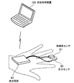
図2は、第2の実施の形態に係る測定システムの構成例を示す図である。図2に示す測定システムは、加速度センサ81、圧力センサ82、検出回路83および測定制御装置100を含む。
加速度センサ81は、3軸方向の加速度を検出するセンサである。加速度センサ81は、測定者(例えば医師)の指の爪側に装着される。圧力センサ82は、同じ指の腹側に装着され、その指によって被検者の腹部を押し込んだときに、指が腹部から受ける圧力を検出可能になっている。なお、以下の説明では、被検者が仰向けに寝た状態で、測定者の指が腹部を下方向に押し込むものとする。
加速度センサ81および圧力センサ82の各検出信号は、信号線を通じて検出回路83に供給される。検出回路83は、例えば、測定者の手の甲や手首、腕など、腹診の動作の邪魔にならない位置に装着される。検出回路83は、加速度センサ81および圧力センサ82から供給された各検出信号を、デジタル方式の測定データに変換する。検出回路83は、変換された測定データを、測定制御装置100に無線送信する。無線による通信方式としては、例えば、Bluetooth(登録商標)を用いることができる。
なお、加速度センサ81、圧力センサ82および検出回路83は、例えば、グローブの表面に装着される。測定者がそのグローブを手に装着することで、加速度センサ81、圧力センサ82および検出回路83は、図2に示すような位置に配置される。
このように、本実施の形態では、モーションキャプチャ用の複数のカメラや変位測定用のゲージ、それらを診察ベッドの周囲に固定するための機構といった大がかりな装置は使用されない。その代わり、測定者の手に装着される加速度センサ81、圧力センサ82および検出回路83というコンパクトな構成によって測定が行われる。
測定制御装置100は、検出回路83から加速度および圧力の測定データを受信する。測定制御装置100は、腹診が行われる間、加速度および圧力の測定データを一定のサンプリング時間間隔で検出回路83から取得する。以下、加速度および圧力の測定データの取得タイミングを「測定ポイント」と記載する場合がある。測定制御装置100は、取得した測定データに基づいて、測定者の指の変位量、すなわち腹部への押し込み量と、圧力のそれぞれの推移を算出する。
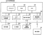
図3は、測定制御装置のハードウェア構成例を示す図である。測定制御装置100は、例えば、図3に示すようなコンピュータとして実現される。
測定制御装置100は、プロセッサ101によって装置全体が制御されている。プロセッサ101は、マルチプロセッサであってもよい。プロセッサ101は、例えばCPU(Central Processing Unit)、MPU(Micro Processing Unit)、DSP(Digital Signal Processor)、ASIC(Application Specific Integrated Circuit)、GPU(Graphics Processing Unit)、またはPLD(Programmable Logic Device)である。また、プロセッサ101は、CPU、MPU、DSP、ASIC、GPU、PLDのうちの2以上の要素の組み合わせであってもよい。
測定制御装置100は、プロセッサ101によって装置全体が制御されている。プロセッサ101は、マルチプロセッサであってもよい。プロセッサ101は、例えばCPU(Central Processing Unit)、MPU(Micro Processing Unit)、DSP(Digital Signal Processor)、ASIC(Application Specific Integrated Circuit)、GPU(Graphics Processing Unit)、またはPLD(Programmable Logic Device)である。また、プロセッサ101は、CPU、MPU、DSP、ASIC、GPU、PLDのうちの2以上の要素の組み合わせであってもよい。
プロセッサ101には、バス108を介して、RAM(Random Access Memory)102と複数の周辺機器が接続されている。
RAM102は、測定制御装置100の主記憶装置として使用される。RAM102には、プロセッサ101に実行させるOS(Operating System)プログラムやアプリケーションプログラムの少なくとも一部が一時的に格納される。また、RAM102には、プロセッサ101による処理に必要な各種データが格納される。
RAM102は、測定制御装置100の主記憶装置として使用される。RAM102には、プロセッサ101に実行させるOS(Operating System)プログラムやアプリケーションプログラムの少なくとも一部が一時的に格納される。また、RAM102には、プロセッサ101による処理に必要な各種データが格納される。
バス108に接続されている周辺機器としては、HDD(Hard Disk Drive)103、グラフィック処理装置104、入力インタフェース105、読み取り装置106および無線通信インタフェース107がある。
HDD103は、測定制御装置100の補助記憶装置として使用される。HDD103には、OSプログラム、アプリケーションプログラム、および各種データが格納される。なお、補助記憶装置としては、SSD(Solid State Drive)などの他の種類の不揮発性記憶装置を使用することもできる。
グラフィック処理装置104には、表示装置104aが接続されている。グラフィック処理装置104は、プロセッサ101からの命令にしたがって、画像を表示装置104aの画面に表示させる。表示装置104aとしては、液晶ディスプレイや有機EL(ElectroLuminescence)ディスプレイなどがある。
入力インタフェース105には、入力装置105aが接続されている。入力インタフェース105は、入力装置105aから出力される信号をプロセッサ101に送信する。入力装置105aとしては、キーボードやポインティングデバイスなどがある。ポインティングデバイスとしては、マウス、タッチパネル、タブレット、タッチパッド、トラックボールなどがある。
読み取り装置106には、可搬型記録媒体106aが脱着される。読み取り装置106は、可搬型記録媒体106aに記録されたデータを読み取ってプロセッサ101に送信する。可搬型記録媒体106aとしては、光ディスク、光磁気ディスク、半導体メモリなどがある。
無線通信インタフェース107は、検出回路83との間でデータを送受信する。
以上のようなハードウェア構成によって、測定制御装置100の処理機能を実現することができる。
以上のようなハードウェア構成によって、測定制御装置100の処理機能を実現することができる。
次に、図4を用いて、加速度センサ81の検出信号に基づいて変位量(押し込み量)を算出する場合の問題点について説明する。
図4は、加速度センサの検出信号に基づく加速度、速度および変位の測定結果の例を示す図である。なお、図4に示す加速度は、指の押し込み方向に沿った上下方向に対する加速度を示す。
図4は、加速度センサの検出信号に基づく加速度、速度および変位の測定結果の例を示す図である。なお、図4に示す加速度は、指の押し込み方向に沿った上下方向に対する加速度を示す。
測定制御装置100は、測定された加速度を積分することで、指の速度を算出できる。また、測定制御装置100は、算出された速度をさらに積分することで、指の変位量を算出できる。図4に示す速度および変位量の推移は、このような手順で加速度の推移に基づいて算出されたものである。腹部の表面に圧力をかけずに指を触れて静止した状態から加速度の測定を行うことで、押し込み開始時の位置を基準とした相対的な指の変位量が算出される。
ここで、腹診の際には、測定者の指は、まず、下方向に対して変位し、最も奥まで押し込まれた後、変位方向が上方向に逆転する。このため、速度は本来、最初のうち負の値をとり、指が最も奥まで押し込まれたときを境に正の値に変化し、指が押し込み開始時の元の位置に戻った時点で0になる。したがって、指の変位量は本来、押し込みが行われている間は負の値をとり、指が押し込み開始時の元の位置に戻った時点で0に戻る。しかし、図4の例では、指が押し込み開始時の元の位置に戻った時点での速度と変位量はともに0になっておらず、正の方向にずれている。
加速度センサ81による加速度の測定値は、他軸感度の影響を受けやすい。上記のように加速度が2回積分されることで、他軸感度の影響によるノイズ成分が増幅され、増幅されたノイズ成分によって変位量に大きな誤差が生じると考えられる。
このような問題に対して、本実施の形態の測定制御装置100は、次の図5で説明する方法によって、加速度を基に算出された速度を補正することで、変位量に生じる誤差を低減する。
図5は、加速度、速度および圧力の測定結果の例を示す図である。これまでの臨床データから、腹診では、腹部に対する押し込み圧力が最大になったとき、指が最も奥まで押し込まれて、その押し込み量(深さ)が最大になるとともに、押し込みの速度が0になることが判明している。
このことを利用して、測定制御装置100は、圧力センサ82によって測定された圧力が最大値(ピーク値)になった時刻Tpにおいて、加速度を基に算出された速度の値(0からのずれ量)を、速度の累積誤差Verrと推定する。そして、測定制御装置100は、静止状態から指の押し込みを開始した押し込み開始時刻(T0とする)から、時刻Tpまでの押し込み時間TMによって、累積誤差Verrを除算する。これによって、単位時間当たりの速度誤差推定値が算出される。測定制御装置100は、押し込み開始時刻T0以降の各測定ポイントについて算出された速度を、速度誤差推定値を用いて補正し、補正後の速度に基づいて変位量を算出する。これにより、変位量に生じる誤差を低減できる。
なお、図5では、説明をわかりやすくするために、時刻Tpにおける速度のずれ量を誇張して描いている。
次に、測定制御装置100の詳細について説明する。
次に、測定制御装置100の詳細について説明する。
図6は、測定制御装置が備える処理機能の構成例を示すブロック図である。測定制御装置100は、測定データ取得部111、速度算出部112、変位算出部113および記憶部114を有する。測定データ取得部111、速度算出部112および変位算出部113の処理は、例えば、プロセッサ101が所定のアプリケーションプログラムを実行することで実現される。記憶部114は、例えば、RAM102またはHDD103の記憶領域として実現される。なお、測定データ取得部111、速度算出部112、変位算出部113は、それぞれ図1に示した取得部11、速度算出部12、押し込み量算出部13の一例である。
測定データ取得部111は、加速度および圧力の測定データを、一定のサンプリング時間間隔で検出回路83から受信し、記憶部114に保存する。また、測定データ取得部111は、加速度の検出データを基に、重力加速度の成分を除去した3次元の加速度ベクトルを算出し、記憶部114に保存する。これにより、測定ポイントごとに、圧力の測定値と加速度ベクトルとが記憶部114に保存される。
速度算出部112は、圧力の測定値に基づいて、押し込み開始時刻T0と、押し込み量が最大となる時刻Tpとを判別する。具体的には、速度算出部112は、測定開始から、圧力の測定値が所定の閾値を超えた時刻を、押し込み開始時刻T0とする。また、速度算出部112は、圧力の測定値が最大の時刻を、押し込み量が最大となる時刻Tpとする。
速度算出部112は、押し込み開始時刻T0以後の各測定ポイントでの加速度ベクトルを用いた積分演算により、各測定ポイントでの速度ベクトルを算出する。また、速度算出部112は、算出された各速度ベクトルのうち上下方向の成分の大きさ(上下方向の速度)を算出する。さらに、速度算出部112は、時刻Tpでの速度を、累積誤差Verrとして抽出する。そして、速度算出部112は、累積誤差Verrを用いて、各測定ポイントでの速度を補正する。
変位算出部113は、補正された速度を用いた積分演算により、各測定ポイントでの変位量(押し込み量)を算出する。変位算出部113は、例えば、押し込み開始時刻T0から時刻Tpまでの各測定ポイントにおける変位量および圧力の推移をデータファイルに書き込み、そのデータファイルを最終的に出力する情報として記憶部114に保存する。
記憶部114には、検出回路83から取得された測定データや、測定データを基に算出された速度や変位量など、測定データ取得部111、速度算出部112、変位算出部113の処理で利用される各種のデータが格納される。
次に、腹診時における測定制御装置100の処理手順について、フローチャートを用いて説明する。
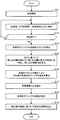
図7は、腹診時における処理手順の例を示すフローチャートである。
図7は、腹診時における処理手順の例を示すフローチャートである。
[ステップS11]測定制御装置100は、測定処理を開始する。例えば、測定者による測定制御装置100に対する測定開始の指示操作に応じて、測定が開始される。
[ステップS12]測定データ取得部111は、加速度および圧力の測定データを検出回路83から受信する。測定データ取得部111は、受信した各測定データを、測定時刻とともに記憶部114に保存する。
[ステップS12]測定データ取得部111は、加速度および圧力の測定データを検出回路83から受信する。測定データ取得部111は、受信した各測定データを、測定時刻とともに記憶部114に保存する。
[ステップS13]測定データ取得部111は、測定を終了するか否かを判定する。例えば、測定者によって測定制御装置100に対する測定終了の指示操作が行われた場合、測定を終了すると判定される。測定を終了する場合、ステップS14の処理が実行される。一方、測定を継続する場合、一定時間が経過した後にステップS12の処理が再度実行される。
[ステップS14]測定データ取得部111は、保存された各測定ポイントにおける加速度の測定データを基に、重力加速度の成分を除去した3次元の加速度ベクトルを算出する。測定データ取得部111は、算出された加速度ベクトルを、測定時刻に対応付けて記憶部114に保存する。
[ステップS15]速度算出部112は、保存された圧力の測定データを参照し、測定開始から圧力が所定の閾値を超えた時刻を、押し込み開始時刻T0と判別する。また、速度算出部112は、押し込み開始時刻T0の後、圧力が最大となった時刻を、押し込み量が最大となる時刻Tpと判別する。さらに、速度算出部112は、押し込み開始時刻T0から時刻Tpまでの押し込み時間TMを算出する。
[ステップS16]速度算出部112は、押し込み開始時刻T0以後の各測定ポイントでの加速度ベクトルを用いた積分演算により、測定ポイントごとの速度ベクトルを算出する。例えば、押し込み開始時刻T0の測定ポイントを1番目の測定ポイントとした場合、n番目の測定ポイントの速度ベクトルは、1番目からn番目の各測定ポイントでの加速度ベクトルを各軸の成分ごとに加算することで算出される。
また、速度算出部112は、算出された各速度ベクトルを基に、指の押し込み方向の成分の速度を算出する。本実施の形態では、押し込み方向は上下方向であるので、上下方向の成分の速度が算出される。
[ステップS17]速度算出部112は、時刻Tpにおける速度を、累積誤差Verrとして抽出する。
[ステップS18]速度算出部112は、ステップS16で算出された、測定ポイントごとの速度を、累積誤差Verrを用いて補正する。
[ステップS18]速度算出部112は、ステップS16で算出された、測定ポイントごとの速度を、累積誤差Verrを用いて補正する。
ここで、押し込み開始時刻T0から測定ポイントまでの時間をtとし、測定ポイントでの補正前の速度をv(t)とする。速度算出部112は、補正後の速度を、v(t)-Verr÷TM×tによって算出する。
[ステップS19]変位算出部113は、測定ポイントごとの補正後の速度を用いた積分演算により、各測定ポイントでの変位量(押し込み量)を算出する。例えば、押し込み開始時刻T0の測定ポイントを1番目の測定ポイントとした場合、n番目の測定ポイントの変位量は、1番目からn番目の各測定ポイントでの補正後の速度を加算することで算出される。
変位算出部113は、最終的な出力情報として、少なくとも時刻Tpにおける変位量を出力する。この変位量は、指の押し込み開始位置から指が最も奥まで押し込まれたときの位置までの距離、すなわち最大押し込み量に相当する。この変位量は、ステップS19において、押し込み開始時刻T0から時刻Tpまでの各測定ポイントについての補正後の速度を加算することで算出される。
また、変位算出部113は、上記の変位量(最大押し込み量)を含む次のような情報を、最終的な出力情報として生成してもよい。例えば、変位算出部113は、時刻Tpにおける変位量と圧力とをデータファイルに書き込み、記憶部114に保存する。あるいは、変位算出部113は、押し込み開始時刻T0から時刻Tpまでの各測定ポイントにおける変位量および圧力の推移をデータファイルに書き込み、記憶部114に保存する。
なお、上記の図7の処理では、一定時間間隔の測定ポイントごとに、加速度センサ81による測定データと圧力センサ82による測定データが取得される。しかし、他の例として、加速度センサ81および圧力センサ82のそれぞれのサンプリングレートを加味して、測定ポイントの間隔が決定されてもよい。
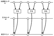
図8は、各センサのサンプリングレートと測定ポイントの間隔との関係の例を示す図である。図8では、加速度センサ81のサンプリングレートが圧力センサ82のサンプリングレートの2倍である例を示している。また、測定ポイントの間隔は、圧力センサ82のサンプリング間隔と一致させている。
この場合、測定データ取得部111は、加速度センサ81での計測のたびに加速度の測定データを受信し、圧力センサ82での計測のたびに圧力の測定データを受信する。測定データ取得部111は、圧力センサ82から受信した1つの測定データを、1つの測定ポイントでの圧力の測定値とする。一方、測定データ取得部111は、加速度センサ81から連続して受信した2つの測定データの平均値を算出し、算出された平均値を、1つの測定ポイントでの加速度の測定値とする。これにより、圧力センサ82のサンプリングの間隔や測定ポイントの間隔が加速度センサ81のサンプリングの間隔より短い場合でも、圧力センサ82で測定されたすべての測定データを利用して押し込み量を算出でき、押し込み量の算出精度を向上させることができる。
次に、補正前の速度および補正後の速度をそれぞれ用いた場合の変位量の算出例について説明する。
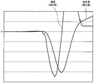
図9は、補正前の速度に基づく変位量の算出例を示す図である。また、図10は、補正後の速度に基づく変位量の算出例を示す図である。なお、参考のために、図9には補正前の速度も示しており、図10には補正後の速度も示している。
図9は、補正前の速度に基づく変位量の算出例を示す図である。また、図10は、補正後の速度に基づく変位量の算出例を示す図である。なお、参考のために、図9には補正前の速度も示しており、図10には補正後の速度も示している。
この例では、時刻Tpにおける補正前の速度に正の誤差が生じているものとする。この場合、時刻Tpにおける補正前の速度を0に近づけるような補正により、補正後の速度は全体的に負の方向に補正される。また、これに伴って、補正後の速度に基づく変位量も全体的に負の方向に補正される。さらに、補正後の速度に基づく変位量については、指が押し込み開始時の元の位置に戻った時点で0に近づくように補正されており、変位量の正確性が高まっていることがわかる。
以上説明した第2の実施の形態に係る測定システムによれば、圧力の測定値を利用することで、加速度の測定値を基に算出された速度を補正できる。その結果、指の変位量、すなわち腹部への押し込み量を高精度に測定できる。
ここで、押し込み量の他の測定方法の例として、モーションキャプチャを用いる方法がある。モーションキャプチャを用いることで、押し込み量を高い分解能で測定できる。しかし、測定者の手や被検者の腹部自体の変形によって生じる死角の影響を回避するために、多数のカメラを用いてさまざまな方向から撮影する必要がある。さらに、カメラ同士の位置関係が変化しないようにするため、大がかりなカメラフレームが必要となる。
これに対して、本実施の形態では、測定者の手に装着される加速度センサ81、圧力センサ82および検出回路83というコンパクトな測定機器を用いたシンプルな構成のシステムにより、指の押し込み量を高精度に測定できる。
なお、上記の各実施の形態に示した装置(押し込み量測定装置10および測定制御装置100)の処理機能は、コンピュータによって実現することができる。その場合、各装置が有すべき機能の処理内容を記述したプログラムが提供され、そのプログラムをコンピュータで実行することにより、上記処理機能がコンピュータ上で実現される。処理内容を記述したプログラムは、コンピュータで読み取り可能な記録媒体に記録しておくことができる。コンピュータで読み取り可能な記録媒体としては、磁気記憶装置、光ディスク、光磁気記録媒体、半導体メモリなどがある。磁気記憶装置には、ハードディスク装置(HDD)、フレキシブルディスク(FD)、磁気テープなどがある。光ディスクには、DVD(Digital Versatile Disc)、DVD-RAM、CD-ROM(Compact Disc-Read Only Memory)、CD-R(Recordable)/RW(ReWritable)などがある。光磁気記録媒体には、MO(Magneto-Optical disk)などがある。
プログラムを流通させる場合には、例えば、そのプログラムが記録されたDVD、CD-ROMなどの可搬型記録媒体が販売される。また、プログラムをサーバコンピュータの記憶装置に格納しておき、ネットワークを介して、サーバコンピュータから他のコンピュータにそのプログラムを転送することもできる。
プログラムを実行するコンピュータは、例えば、可搬型記録媒体に記録されたプログラムまたはサーバコンピュータから転送されたプログラムを、自己の記憶装置に格納する。そして、コンピュータは、自己の記憶装置からプログラムを読み取り、プログラムにしたがった処理を実行する。なお、コンピュータは、可搬型記録媒体から直接プログラムを読み取り、そのプログラムにしたがった処理を実行することもできる。また、コンピュータは、ネットワークを介して接続されたサーバコンピュータからプログラムが転送されるごとに、逐次、受け取ったプログラムにしたがった処理を実行することもできる。
上記については単に本発明の原理を示すものである。さらに、多数の変形、変更が当業者にとって可能であり、本発明は上記に示し、説明した正確な構成および応用例に限定されるものではなく、対応するすべての変形例および均等物は、添付の請求項およびその均等物による本発明の範囲とみなされる。
1,2 部位
1a 加速度センサ
1b 圧力センサ
10 押し込み量測定装置
11 取得部
12 速度算出部
13 押し込み量算出部
21~23 グラフ
1a 加速度センサ
1b 圧力センサ
10 押し込み量測定装置
11 取得部
12 速度算出部
13 押し込み量算出部
21~23 グラフ
Claims (6)
- 測定者の身体の第1の部位が被検者の身体の第2の部位を押し込む押し込み動作の実行中に、前記第1の部位に装着された加速度センサによる検出結果と、前記第1の部位の押し込み面に装着された圧力センサによる検出結果とを取得する取得部と、
前記加速度センサによって検出された加速度を積分することで、前記押し込み動作の開始からの複数の測定タイミングのそれぞれにおける前記第1の部位の複数の第1の速度を算出し、前記複数の測定タイミングのうち、前記圧力センサによって検出された圧力が最大となる特定タイミングにおける速度が0になるように、前記複数の第1の速度をそれぞれ補正して複数の第2の速度を算出する速度算出部と、
前記複数の第2の速度を積分することで、前記第1の部位の押し込み量を算出する押し込み量算出部と、
を有する押し込み量測定装置。 - 前記速度算出部は、前記複数の第1の速度のうち、前記特定タイミングにおける速度を第3の速度として抽出し、前記第3の速度に基づいて単位時間当たりの誤差の発生量を算出し、前記誤差の発生量に基づいて前記複数の第1の速度を補正する、
請求項1記載の押し込み量測定装置。 - 前記押し込み量算出部は、前記特定タイミングにおける前記第1の部位の押し込み量を算出する、
請求項1または2記載の押し込み量測定装置。 - 前記速度算出部は、前記圧力センサによって検出された圧力が所定の閾値を超えたとき、前記押し込み動作が開始されたと判定する、
請求項1乃至3のいずれか1項に記載の押し込み量測定装置。 - コンピュータが、
測定者の身体の第1の部位が被検者の身体の第2の部位を押し込む押し込み動作の実行中に、前記第1の部位に装着された加速度センサによる検出結果と、前記第1の部位の押し込み面に装着された圧力センサによる検出結果とを取得し、
前記加速度センサによって検出された加速度を積分することで、前記押し込み動作の開始からの複数の測定タイミングのそれぞれにおける前記第1の部位の複数の第1の速度を算出し、
前記複数の測定タイミングのうち、前記圧力センサによって検出された圧力が最大となる特定タイミングにおける速度が0になるように、前記複数の第1の速度をそれぞれ補正して複数の第2の速度を算出し、
前記複数の第2の速度を積分することで、前記第1の部位の押し込み量を算出する、
押し込み量測定方法。 - コンピュータに、
測定者の身体の第1の部位が被検者の身体の第2の部位を押し込む押し込み動作の実行中に、前記第1の部位に装着された加速度センサによる検出結果と、前記第1の部位の押し込み面に装着された圧力センサによる検出結果とを取得し、
前記加速度センサによって検出された加速度を積分することで、前記押し込み動作の開始からの複数の測定タイミングのそれぞれにおける前記第1の部位の複数の第1の速度を算出し、
前記複数の測定タイミングのうち、前記圧力センサによって検出された圧力が最大となる特定タイミングにおける速度が0になるように、前記複数の第1の速度をそれぞれ補正して複数の第2の速度を算出し、
前記複数の第2の速度を積分することで、前記第1の部位の押し込み量を算出する、
処理を実行させる押し込み量測定プログラム。
Priority Applications (2)
| Application Number | Priority Date | Filing Date | Title |
|---|---|---|---|
| PCT/JP2016/068770 WO2017221394A1 (ja) | 2016-06-24 | 2016-06-24 | 押し込み量測定装置、押し込み量測定方法および押し込み量測定プログラム |
| JP2018523245A JP6649594B2 (ja) | 2016-06-24 | 2016-06-24 | 押し込み量測定装置、押し込み量測定方法および押し込み量測定プログラム |
Applications Claiming Priority (1)
| Application Number | Priority Date | Filing Date | Title |
|---|---|---|---|
| PCT/JP2016/068770 WO2017221394A1 (ja) | 2016-06-24 | 2016-06-24 | 押し込み量測定装置、押し込み量測定方法および押し込み量測定プログラム |
Publications (1)
| Publication Number | Publication Date |
|---|---|
| WO2017221394A1 true WO2017221394A1 (ja) | 2017-12-28 |
Family
ID=60783941
Family Applications (1)
| Application Number | Title | Priority Date | Filing Date |
|---|---|---|---|
| PCT/JP2016/068770 Ceased WO2017221394A1 (ja) | 2016-06-24 | 2016-06-24 | 押し込み量測定装置、押し込み量測定方法および押し込み量測定プログラム |
Country Status (2)
| Country | Link |
|---|---|
| JP (1) | JP6649594B2 (ja) |
| WO (1) | WO2017221394A1 (ja) |
Citations (3)
| Publication number | Priority date | Publication date | Assignee | Title |
|---|---|---|---|---|
| JP2001037740A (ja) * | 1999-05-31 | 2001-02-13 | Laerdal Medical As | 救命状況又はその練習状況における胸部圧縮の際にパラメータを測定及び利用する装置 |
| WO2012073900A1 (ja) * | 2010-11-29 | 2012-06-07 | 株式会社日立製作所 | 圧迫深度計算システムおよび圧迫深度計算方法 |
| JP2015058286A (ja) * | 2013-09-20 | 2015-03-30 | 富士通株式会社 | 触診センサおよび触診システム |
Family Cites Families (2)
| Publication number | Priority date | Publication date | Assignee | Title |
|---|---|---|---|---|
| JP3867331B2 (ja) * | 1997-01-28 | 2007-01-10 | セイコーエプソン株式会社 | 弾性係数測定装置および触診装置 |
| JP6164641B2 (ja) * | 2012-07-20 | 2017-07-19 | 株式会社タニタ | 粘弾性測定装置 |
-
2016
- 2016-06-24 JP JP2018523245A patent/JP6649594B2/ja not_active Expired - Fee Related
- 2016-06-24 WO PCT/JP2016/068770 patent/WO2017221394A1/ja not_active Ceased
Patent Citations (3)
| Publication number | Priority date | Publication date | Assignee | Title |
|---|---|---|---|---|
| JP2001037740A (ja) * | 1999-05-31 | 2001-02-13 | Laerdal Medical As | 救命状況又はその練習状況における胸部圧縮の際にパラメータを測定及び利用する装置 |
| WO2012073900A1 (ja) * | 2010-11-29 | 2012-06-07 | 株式会社日立製作所 | 圧迫深度計算システムおよび圧迫深度計算方法 |
| JP2015058286A (ja) * | 2013-09-20 | 2015-03-30 | 富士通株式会社 | 触診センサおよび触診システム |
Also Published As
| Publication number | Publication date |
|---|---|
| JP6649594B2 (ja) | 2020-02-19 |
| JPWO2017221394A1 (ja) | 2019-04-18 |
Similar Documents
| Publication | Publication Date | Title |
|---|---|---|
| US10383531B2 (en) | Physiological signals measurement systems and methods thereof | |
| US10219752B2 (en) | Apparatus and method for analyzing living body information | |
| WO2015186586A1 (ja) | リハビリテーション支援システム | |
| KR102505348B1 (ko) | 생체 정보 처리 장치 및 방법 | |
| TW201305884A (zh) | 觸控裝置及使用該觸控裝置的滑鼠 | |
| JP2016515742A (ja) | ジェスチャタッチジオメトリのid追跡 | |
| CN111816292A (zh) | 一种诊脉系统与方法 | |
| JP6366463B2 (ja) | 血圧測定装置 | |
| JP2016087005A (ja) | 血圧測定装置 | |
| KR20150114285A (ko) | 초음파 진단 장치 및 그 동작방법 | |
| KR20200050905A (ko) | 사용자의 의도 예측 방법 및 이를 수행하기 위한 장치 | |
| JP2009128969A5 (ja) | ||
| JP7030700B2 (ja) | 超音波システム及び方法 | |
| CN108024743B (zh) | 血压分析装置、血压测定装置、血压分析方法、血压分析程序 | |
| JP6649594B2 (ja) | 押し込み量測定装置、押し込み量測定方法および押し込み量測定プログラム | |
| US11717184B2 (en) | Tracking head motion for medical imaging | |
| JP2021129628A (ja) | 超音波診断装置、方法およびプログラム | |
| US20250190073A1 (en) | Finger tapping measurement processing terminal, system, method, and computer program | |
| CN105615861B (zh) | 一种测量脉搏的方法及电子设备 | |
| US20260020777A1 (en) | Obtaining Biometric Information of a User Based on a Ballistocardiogram Signal Obtained When a Mobile Computing Devie is Held Against the Head of the User | |
| JP7335046B2 (ja) | 歩行分析装置、歩行分析方法、及びプログラム | |
| EP3677175A1 (en) | Artery sensing | |
| JP6627971B2 (ja) | 情報処理装置、情報処理方法、および情報処理プログラム | |
| KR102008496B1 (ko) | 단일 센서를 이용하여 기구물의 이동 방향 및 속도를 검출하는 방법 및 장치. | |
| WO2024118687A1 (en) | Mobile device based oscillometric blood pressure measurement |
Legal Events
| Date | Code | Title | Description |
|---|---|---|---|
| ENP | Entry into the national phase |
Ref document number: 2018523245 Country of ref document: JP Kind code of ref document: A |
|
| 121 | Ep: the epo has been informed by wipo that ep was designated in this application |
Ref document number: 16906311 Country of ref document: EP Kind code of ref document: A1 |
|
| NENP | Non-entry into the national phase |
Ref country code: DE |
|
| 122 | Ep: pct application non-entry in european phase |
Ref document number: 16906311 Country of ref document: EP Kind code of ref document: A1 |