WO2017213005A1 - 磁界測定装置 - Google Patents
磁界測定装置 Download PDFInfo
- Publication number
- WO2017213005A1 WO2017213005A1 PCT/JP2017/020331 JP2017020331W WO2017213005A1 WO 2017213005 A1 WO2017213005 A1 WO 2017213005A1 JP 2017020331 W JP2017020331 W JP 2017020331W WO 2017213005 A1 WO2017213005 A1 WO 2017213005A1
- Authority
- WO
- WIPO (PCT)
- Prior art keywords
- magnetic field
- magnetic
- measurement
- sensor
- coil
- Prior art date
- Legal status (The legal status is an assumption and is not a legal conclusion. Google has not performed a legal analysis and makes no representation as to the accuracy of the status listed.)
- Ceased
Links
Images






Classifications
-
- G—PHYSICS
- G01—MEASURING; TESTING
- G01N—INVESTIGATING OR ANALYSING MATERIALS BY DETERMINING THEIR CHEMICAL OR PHYSICAL PROPERTIES
- G01N27/00—Investigating or analysing materials by the use of electric, electrochemical, or magnetic means
- G01N27/72—Investigating or analysing materials by the use of electric, electrochemical, or magnetic means by investigating magnetic variables
-
- G—PHYSICS
- G01—MEASURING; TESTING
- G01R—MEASURING ELECTRIC VARIABLES; MEASURING MAGNETIC VARIABLES
- G01R33/00—Arrangements or instruments for measuring magnetic variables
- G01R33/02—Measuring direction or magnitude of magnetic fields or magnetic flux
Definitions
- the present invention relates to a magnetic field measurement apparatus including a magnetic field generation unit that generates a magnetic field that acts on a measurement object and a magneto-impedance sensor that measures the magnetic field generated from the measurement object.
- the present invention relates to a magnetic field measuring apparatus that can measure a magnetic field of a measurement object with high accuracy even when a strong magnetic field from a magnetic field generating unit acts on a magneto-impedance sensor.
- a magnetic field measuring apparatus such as a magnetic inspection apparatus, which includes a magnetic field generating unit that generates a magnetic field for measurement, which is a magnetic field acting on a measurement object, and a magneto-impedance sensor (hereinafter also referred to as MI sensor) is known.
- MI sensor magneto-impedance sensor
- the magnetic field measurement device is used, for example, as a foreign matter detection device that detects foreign matter made of metal or a magnetic substance contained in food or the like, or a rotational speed calculation device that calculates the rotational speed of a metal gear (see FIG. 8). .
- the MI sensor includes a magnetic sensor made of an amorphous wire and a detection coil wound around the magnetic sensor.
- the detection coil outputs an output voltage corresponding to the magnetic field acting on the magnetic sensitive body.
- the MI sensor is configured to measure the strength of the magnetic field generated from the measurement object by measuring the output voltage.
- the magnetic field measuring apparatus since the magnetic field measuring apparatus generates a relatively strong magnetic field for measurement from the magnetic field generator, the magnetic field for measurement also acts on the magnetic sensitive body. Unlike the other magnetic sensors, the output voltage of the MI sensor does not saturate even if a strong magnetic field acts in a direction perpendicular to the magnetic sensing direction (axial direction) of the magnetic sensor. Therefore, the MI sensor can be used without any problem even when a strong measurement magnetic field acts in a direction perpendicular to the magnetic sensitive body. However, even if the MI sensor is consciously arranged so that the magnetic field for measurement acts in the direction perpendicular to the magnetic sensitive direction and not in the magnetic sensitive direction, the measurement magnetic field is measured in the magnetic sensitive direction due to some misalignment.
- the present invention has been made in view of such a background, and even if the magnetic field generated from the magnetic field generator acts in the magnetic sensing direction of the magnetic sensor of the MI sensor, the MI sensor is not adjusted without adjusting the position of the MI sensor. It is an object of the present invention to provide a magnetic field measuring apparatus that can be adjusted so as not to saturate its output.
- One aspect of the present invention is a magnetic field generation unit that generates a measurement magnetic field that is a magnetic field acting on a measurement object;
- a magneto-impedance sensor for measuring a magnetic field to be measured which is a magnetic field generated from the measurement object by the action of the measurement magnetic field;
- the magneto-impedance sensor has a magnetic sensor, a detection coil wound around the magnetic sensor, and a measurement circuit that measures an output voltage of the detection coil.
- the magneto-impedance sensor is arranged at a position where the measurement magnetic field acts on the magnetic sensitive body,
- a canceling coil is wound around the magnetosensitive body, and the magnetic field generated by energizing the canceling coil is configured to cancel the component of the measuring magnetic field acting on the magnetic sensitive body in the magnetic sensing direction of the magnetosensitive body.
- the magnetic field measuring apparatus is characterized in that (Claim 1).
- the canceling coil capable of canceling a predetermined amount of the magnetosensitive direction component of the magnetic field for measurement is wound around the magnetic sensitive body. Therefore, the component in the magnetic sensing direction of the measurement magnetic field acting on the magnetic sensitive body can be canceled by the magnetic field generated by energizing the cancellation coil. Therefore, even if a magnetic field acts on the magnetic sensing element in the direction of magnetic sensing, it can be adjusted so that the output of the MI sensor does not saturate even if the position of the MI sensor is not adjusted by canceling the action by the cancellation coil. can do. Therefore, the magnetic field generated from the measurement object can be accurately measured by the MI sensor.
- “cancel” in the present invention does not necessarily mean that the value is completely zero. Of course, even if it is completely zero, there is no problem, but if it is canceled to the extent that the output of the MI sensor does not saturate, measurement can be performed without any problem.
- the magnetic field measurement can be adjusted so that the output of the MI sensor is not saturated.
- An apparatus can be provided.
- FIG. 1 is a conceptual diagram of a magnetic field measurement device in Embodiment 1.
- FIG. FIG. 3 is a plan view of a magnetoimpedance element in the first embodiment.
- 3 is a graph showing a relationship between a magnetic sensing direction component of a magnetic field acting on a magnetic sensing body and an output voltage in the first embodiment.
- 1 is a schematic circuit diagram of a magnetic field measuring apparatus in Embodiment 1.
- FIG. 1 is a schematic circuit diagram of a magnetic field measuring apparatus in Embodiment 1.
- FIG. 10 is a plan view of a magnetoimpedance element in the fifth embodiment. XI-XI sectional drawing of FIG.
- FIG. 7 The conceptual diagram of the magnetic field measuring apparatus in Embodiment 7.
- the orientation of the magnetic sensitive body is determined so that a component in the magnetic sensitive direction of the magnetic field for measurement acting on the magnetic sensitive body is smaller than a component in a direction perpendicular to the magnetic sensitive direction.
- the MI sensor is basically arranged so that the magnetic field for measurement does not act in the magnetosensitive direction.
- a canceling coil is provided in the present invention, even if the MI sensor is arranged so that a large magnetic field for measurement acts in the magnetosensitive direction by adjusting the strength of the current flowing through the canceling coil. It is possible to adjust so that the output voltage of the MI sensor does not saturate.
- the magnetic field generator is an electromagnetic coil, preferably configured to flow an alternating current through the electromagnetic coil, and configured to flow a current synchronized with the alternating current through the cancellation coil. .
- an alternating magnetic field can be generated from the electromagnetic coil. Therefore, for example, when the measurement object is a non-magnetic material and is a conductive material, an eddy current can be passed through the measurement object, and the magnetic field generated along with this can be measured by the MI sensor. become. Therefore, even if the measurement object is not a magnetic material, the magnetic field generated from the measurement object can be measured.
- an AC magnetic field (measurement magnetic field) generated from the electromagnetic coil acts on the magnetic sensitive body. That is, a measurement magnetic field that changes with time acts on the magnetic sensitive body.
- the current synchronized with the alternating current flowing through the electromagnetic coil is passed through the cancellation coil, even if the magnetically sensitive direction component of the magnetic field for measurement acting on the magnetic sensitive body changes over time, Can be canceled accurately.
- the magnetic field generator is preferably a permanent magnet. In this case, a magnetic field can be generated without supplying power to the magnetic field generator. Therefore, it is possible to save power in the magnetic field measuring device.
- the detection coil and the cancellation coil are wound concentrically around the magnetic sensitive body.
- the axial length of the magnetic sensitive body can be shortened compared to the case where the detection coil and the cancellation coil are formed at positions adjacent to each other in the axial direction. Therefore, the manufacturing cost of the MI sensor can be reduced.
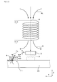
- the magnetic field measurement apparatus 1 of this embodiment includes a magnetic field generation unit 2 and a magnetoimpedance sensor 3 (MI sensor).
- the magnetic field generator 2 generates a measurement magnetic field H 1 that is a magnetic field acting on the measurement object 4.
- the MI sensor 3 measures a magnetic field H 2 to be measured, which is a magnetic field generated from the measurement object 4 by the action of the measurement magnetic field H 1 .
- the MI sensor 3 includes a magnetosensitive body 31, a detection coil 32, and a measurement circuit 33.
- the detection coil 32 is wound around the magnetic sensitive body 31.
- the measurement circuit 33 measures the output voltage V o of the detection coil 32.
- the MI sensor 3 is arranged at a position where the measurement magnetic field H 1 acts on the magnetic sensitive body 31.
- the MI sensor 3 is disposed immediately below the magnetic field generator 3.
- a cancellation coil 34 is wound around the magnetic sensitive body 31.
- a component in the magnetic sensing direction (axial direction: X direction) of the magnetic sensing element 31 of the measurement magnetic field H 1 acting on the magnetic sensing element 31 by the magnetic field H 3 generated by energizing the cancellation coil 34 hereinafter referred to as the magnetic sensing direction).
- component H 1X component
- an electromagnetic coil 2 E is used as the magnetic field generator 2.
- an electromagnetic coil 2 E By passing an alternating current i to the electromagnetic coil 2, an electromagnetic coil 2 E, it is generating the coil magnetic field H 1 (AC magnetic field).
- the measurement magnetic field H 1 is applied to the inspection object 11 such as food.
- a measured magnetic field H 2 is generated around the measurement object 4. That is, for example, when the measurement object 4 is a magnetic body, the measurement object 4 is magnetized by the measurement magnetic field H 1 , and a measured magnetic field H 2 is generated around it.
- the measurement object 4 is a metal
- an eddy current flows through the measurement object 4, and as a result, a magnetic field (measured magnetic field H 2 ) caused by the eddy current is generated around the object.
- the magnetic field H 2 By measuring the magnetic field H 2 to be measured by the MI sensor 3, it is configured to determine whether or not a foreign object (measurement object 4) is mixed in the inspection object 11.
- the magnetic sensitive member 31 is disposed on the central axis A of the electromagnetic coil 2 E.
- the coil magnetic field H 1 generated from the electromagnetic coil 2 E it is desirable to be perfectly symmetrical with respect to the central axis A of the electromagnetic coils 2 E, complete alignment is difficult. Therefore, even if the magnetic sensitive body 31 is arranged on the central axis A, the magnetic sensitive direction component H 1X is always generated due to a slight deviation. Further, when the magnetic field measuring apparatus 1 is manufactured, the magnetic sensitive body 31 may be arranged at a position shifted from the central axis A. This also becomes a factor of the magnetism-sensitive direction component H 1X occurs. In the present embodiment, this magnetosensitive direction component H 1X can be canceled by the magnetic field H 3 of the cancellation coil 34.
- the MI sensor 3 includes a magneto-impedance element 30 (hereinafter also referred to as MI element 30), an IC 35, and a wiring board 39 on which these are mounted.
- the MI element 30 includes a magnetosensitive body 31, a detection coil 32, a cancellation coil 34, and a sensor substrate 301 on which these are placed.
- the magnetic sensitive body 31 is made of an amorphous wire having zero magnetostriction.
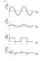
- FIG. 4 is a graph showing temporal changes of the current i flowing through the electromagnetic coil 2 E , the current I flowing through the cancellation coil 34, the current I P flowing through the magnetic sensitive body 31, and the output voltage V O of the detection coil 32. Indicates. As shown in the figure, the current i flowing through the electromagnetic coil 2 E and the current I flowing through the cancellation coil 34 are synchronized. By passing a current I through the canceling coil 34, a magnetic field H 3 (see FIG. 2) is generated, and the magnetic sensing direction component H 1X of the measurement magnetic field H 1 acting on the magnetic sensitive body 31 is canceled.
- the inspection object 11 acting on the MI sensor 3 becomes closer as the inspection object 11 approaches the MI sensor 3.
- the strength of the measurement magnetic field H 2 increases. Therefore, as shown in FIG. 3, the output voltage V O has a peak value at a predetermined time t 0 and then decreases.
- the MI sensor 3 determines that the measurement object 4 (foreign matter) is mixed in the inspection object 11 when the output voltage V O exceeds a predetermined threshold value V th .
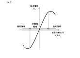
- the magnetosensitive direction component H 1X of the measuring magnetic field H 1 acting on the magnetic sensitive body 31 is canceled by the magnetic field H 3 generated by energizing the cancellation coil 34. Therefore, the output voltage V O resulting from the measured magnetic field H 2 can be accurately measured. That is, as shown in FIG. 5, the output voltage V O of the MI sensor 3 does not saturate when the magnetic direction component H X of the magnetic field applied to the magnetic body 31 is small. That is, an output voltage V O proportional to the magnetic sensitive direction component H X can be obtained. On the other hand, when the magnetosensitive direction component H X becomes high, the MI sensor 3 enters the saturation region, and the output voltage V O proportional to the magnetosensitive direction component H X cannot be obtained.
- the MI sensor 3 can be used in the non-saturated region because the magnetosensitive direction component H 1X of the measurement magnetic field H 1 acting on the magnetic sensitive body 31 is canceled by the cancellation coil 34. . Therefore, it is possible to accurately measure the magnetically sensitive direction component of the magnetic field H 2 generated from the measurement object 4 and acting on the magnetic sensitive body 31.
- the MI sensor 3 of the present embodiment includes the MI element 30, the IC 35, and the wiring board 39.
- a pulse generation circuit 351 a measurement circuit 33, a synchronization circuit 36, a CPU 353, a ROM 354, and a RAM 355 are formed.
- the pulse generation circuit 351 is connected to the magnetic sensitive body 31.
- a pulse wave (current I P ) is passed from the pulse generation circuit 351 to the magnetic sensitive body 31.
- the measurement circuit 33 measures the output voltage V O of the detection coil 32.
- the measurement circuit 33 includes a sample hold circuit (not shown) that holds the output voltage V O for a certain period, and an A / D converter (not shown) that converts the held output voltage V O into a digital value.
- the electromagnetic coil 2 E is connected to the drive circuit 12.
- a current i (alternating current) is passed from the drive circuit 12 to the electromagnetic coil 2 E.
- the synchronization circuit 36 formed in the IC 35 causes the current I synchronized with the current i to flow through the electromagnetic coil 2 E to flow through the cancellation coil 34.
- the magnetosensitive component H 1X of the measurement magnetic field H 1 acting on the magnetosensitive body 31 is canceled out.
- the ROM 354 stores a determination program 356.
- the CPU 353 reads out and executes the determination program 356. Thereby, it is comprised so that it may be judged whether the foreign material (measurement object 4) is mixed in the test object 11 (refer FIG. 1).
- a cancellation coil 34 is wound around the magnetic sensitive body 31. Therefore, the magnetosensitive direction component H 1X of the measurement magnetic field H 1 acting on the magnetic sensitive body 31 can be canceled by the magnetic field H 3 generated by energizing the cancellation coil 34. Therefore, even if a strong magnetic field acts on the magnetic sensitive body 31 in the magnetic sensitive direction, the output of the MI sensor 3 can be adjusted not to be saturated by canceling the magnetic sensitive direction component. Therefore, the magnetic field H 2 to be measured generated from the measuring object 4 can be accurately measured by the MI sensor 3.
- the position and orientation of the MI sensor 3 are adjusted so that the component H 1X of the measurement magnetic field H 1 acting on the magnetic sensitive body 31 is as close to 0 as possible. ing.
- the magnetosensitive direction component H 1X is made smaller than the component (orthogonal direction component H 1Z ) in the direction (Z direction) orthogonal to the magnetosensitive direction.
- the magnetic sensing direction component H 1X of the magnetic field for measurement H 1 acting on the magnetic sensing body 31 is small, the magnetic sensing direction component H 1X can be canceled without passing a large current through the cancellation coil 31. it can. Therefore, it is possible to save power in the magnetic field measuring apparatus 1.
- the output voltage V O of the MI sensor 3 does not saturate, so that no significant problem occurs.
- the magnetic field generator 2 of this embodiment is an electromagnetic coil 2 E , and is configured to pass an alternating current i through the electromagnetic coil 2 E. And it is comprised so that the electric current I synchronizing with the alternating current i may be sent through the cancellation coil 34. FIG. Therefore, it generates an AC magnetic field from the electromagnetic coil 2 E. Therefore, for example, when the measuring object 4 is a non-magnetic material and is a conductive material, an eddy current can be passed through the measuring object 4 and the magnetic field generated thereby is measured by the MI sensor 3. It becomes possible to do. Therefore, even if the measuring object 4 is not a magnetic body, the magnetic field generated from the measuring object 4 can be measured.
- an alternating magnetic field (measurement magnetic field H 1 ) generated from the electromagnetic coil 2 acts on the magnetic sensitive body 31. That is, the measurement magnetic field H 1 that changes with time acts on the magnetic sensitive body 31.
- the magnetically sensitive direction component H 1X of the measuring magnetic field H 1 acting on the magnetic sensitive body 31 is temporal. Even if it changes to, this can be canceled accurately.
- the MI element 30 of this embodiment includes two detection coils 32, a first detection coil 32a and a second detection coil 32b.
- a canceling coil 34 is formed between the two detection coils 32a and 32b. Therefore, the two detection coils 32a and 32b can be arranged at positions where the cancellation coil 34 is sandwiched from both sides, and the symmetry of the MI element 30 can be enhanced. Therefore, the measurement accuracy of the measured magnetic field H 2 can be increased.
- the present embodiment it is possible to provide a magnetic field measuring apparatus in which the output of the magneto-impedance sensor is less likely to be saturated even when a magnetic field generated from the magnetic field generator acts.
- Embodiment 2 This embodiment is an example in which the configuration of the magnetic field generator 2 is changed.
- a permanent magnet 2 P is used as the magnetic field generator 2.
- a measurement magnetic field H 1 generated from the permanent magnet 2 P is applied to the detection target 11.
- the measured magnetic field H 2 generated from the foreign matter (measurement target 4) existing in the detection target 11 is measured by the MI sensor 3. Accordingly, it is configured to check whether or not foreign matter is mixed in the detection target 11.
- the measurement magnetic field H 1 can be generated without supplying power to the magnetic field generator 2. Therefore, it is possible to save power in the magnetic field measuring apparatus 1.
- the same configuration and operational effects as those of the first embodiment are provided.
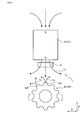
- the magnetic field measurement device 1 is used as a rotation speed measurement device that measures the rotation speed of the gear 49 (measurement object 4).
- the gear 49 is made of a magnetic material.
- the measurement magnetic field H 1 generated from the magnetic field generator 2 is applied to the gear 49.
- the gear 49 is magnetized, and the magnetic field H 2 to be measured is generated from the gear 49.
- the magnetic field H 2 to be measured generated from the teeth 48 of the gear 49 is periodically measured by the MI sensor 3.
- the output voltage V o of the MI sensor 3 periodically increases or decreases depending on the shape of the tooth shape of the gear 49. By measuring the period of the output voltage V o , the rotational speed of the gear 49 is detected.
- the same configuration and operational effects as those of the first embodiment are provided.
- the MI element 30 of this embodiment includes two canceling coils 34, a first canceling coil 34a and a second canceling coil 34b.
- a detection coil 32 is formed between the two canceling coils 34a and 34b.
- the two canceling coils 34a and 34b are arranged at positions sandwiching the detection coil 32 from both sides, so that the symmetry of the MI element 30 can be increased. Therefore, the detection accuracy of the magnetic field H 2 to be measured by the MI element 30 can be increased.
- This embodiment is an example in which the configuration of the MI element 30 is changed.
- the detection coil 32 and the cancellation coil 34 are concentrically wound around the magnetic sensitive body 31.
- the cancellation coil 34 is wound around the outside of the detection coil 32.
- An insulating layer (not shown) is interposed between the magnetic sensitive body 31 and the detection coil 32 and between the detection coil 32 and the cancellation coil 34.
- the length of the magnetic sensitive body 31 in the X direction can be shortened compared to the case where the two coils 32 and 34 are formed at positions adjacent to each other in the X direction (see FIG. 2). Therefore, the manufacturing cost of MI element 30 can be reduced. Moreover, if it is set as the said structure, compared with Embodiment 1 (refer FIG. 2), the number of turns of the cancellation coil 34 can be increased, without lengthening the X direction length of the magnetic body 31. FIG. Therefore, the magnetic field H 3 generated from the cancellation coil 34 can be increased without increasing the length of the magnetic sensitive body 31 in the X direction.
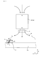
- This embodiment is an example in which the arrangement position of the MI sensor 3 is changed. As shown in FIG. 12, in this embodiment, the MI sensor 3 is arranged at a position closer to the belt conveyor 19 than the magnetic field generator 2. When the inspection object 11 is closest to the MI sensor 3, the distance from the MI sensor 3 to the detection object 11 is shorter than the distance from the MI sensor 3 to the magnetic field generator 2.
- the MI sensor 3 are arranged on the extension of the center axis A of the electromagnetic coil 2 E.
- the magnetic sensing direction component H 1X of the measurement magnetic field H 1 acting on the magnetic sensing body 31 in the MI sensor 3 is smaller than the vertical direction component H 1Z .
- the magnetic field H 2 to be measured generated from the object to be measured 4 can be made to act strongly on the MI sensor 3. Therefore, the measurement sensitivity of the magnetic field H 2 to be measured by the MI sensor 3 can be increased.
- the same configuration and operational effects as those of the first embodiment are provided.
- This embodiment is an example in which the arrangement position of the MI sensor 3 is changed. As shown in FIG. 13, in this embodiment the MI sensor 3, is arranged at a position deviated from the extension of the center axis A of the electromagnetic coil 2 E. In this embodiment, the magnetic sensing direction component H 1X of the measurement magnetic field H 1 acting on the magnetic sensing body 31 in the MI sensor 3 is larger than the vertical direction component H 1Z .
- the degree of freedom of the arrangement position of the MI sensor 3 can be increased. Therefore, it becomes easy to design the magnetic field measuring apparatus 1.
- the canceling coil 34 is wound around the magnetic sensitive body 31 as in the first embodiment. Therefore, even if the magnetic sensitive direction component H 1X of the measurement magnetic field H 1 acting on the magnetic sensitive body 31 is large, This magnetosensitive direction component H 1X can be sufficiently canceled out. Therefore, the MI sensor 3 can be disposed at an arbitrary location.
- the same configuration and operational effects as those of the first embodiment are provided.
Landscapes
- Physics & Mathematics (AREA)
- General Physics & Mathematics (AREA)
- Chemical & Material Sciences (AREA)
- General Health & Medical Sciences (AREA)
- Health & Medical Sciences (AREA)
- Life Sciences & Earth Sciences (AREA)
- Analytical Chemistry (AREA)
- Biochemistry (AREA)
- Electrochemistry (AREA)
- Chemical Kinetics & Catalysis (AREA)
- Immunology (AREA)
- Pathology (AREA)
- Condensed Matter Physics & Semiconductors (AREA)
- Measuring Magnetic Variables (AREA)
- Investigating Or Analyzing Materials By The Use Of Magnetic Means (AREA)
Abstract
磁界発生部から発生した磁界が作用しても、マグネトインピーダンスセンサが飽和しにくい磁界測定装置を提供すること。磁界発生部(2)と、MIセンサ(3)とを備える。磁界発生部(2)は、測定対象物(4)に作用する磁界である測定用磁界(H1)を発生する。また、MIセンサ(3)は、測定対象物(4)から発生した磁界である被測定磁界(H2)を測定する。MIセンサ(3)は、感磁体(31)と、検出コイル(32)と、測定回路(33)と、打消コイル(34)とを備える。MIセンサ(3)は、感磁体(31)に測定用磁界(H1)が作用する位置に配されている。打消コイル(34)への通電により発生した磁界(H3)により、感磁体(31)に作用する測定用磁界(H1)の、感磁体(31)の感磁方向における成分(H1X)を打ち消すよう構成されている。
Description
本発明は、測定対象物に作用する磁界を発生する磁界発生部と、上記測定対象物から発生した磁界を測定するマグネトインピーダンスセンサとを備える磁界測定装置に関する。特に、磁界発生部から強い磁界がマグネトインピーダンスセンサに作用しても、測定対象物の磁界を高い精度で測定できる磁界測定装置に関する。
従来から、測定対象物に作用する磁界である測定用磁界を発生する磁界発生部と、マグネトインピーダンスセンサ(以下、MIセンサとも記す)とを備えた、磁気検査装置等の磁界測定装置が知られている(下記特許文献1参照)。この磁界測定装置では、上記測定用磁界を上記測定対象物に作用させ、この測定対象物を磁化させたり、測定対象物内に渦電流を流したりしている。これによって測定対象物の周囲に発生した磁界を、MIセンサによって測定することにより、測定対象物の有無等を検出するように構成されている。磁界測定装置は、例えば、食品等に含まれる、金属や磁性体からなる異物を検出する異物検出装置や、金属製の歯車(図8参照)の回転速度を算出する回転速度算出装置として用いられる。
MIセンサは、アモルファスワイヤからなる感磁体と、該感磁体に巻回した検出コイルとを備える。検出コイルは、感磁体に作用する磁界に対応した出力電圧を出力する。MIセンサは、この出力電圧を測定することにより、上記測定対象物から発生した磁界の強さを測定するよう構成されている。
しかしながら、上記磁界測定装置では、磁界発生部から比較的強い測定用磁界を発生しているため、この測定用磁界は、感磁体にも作用することとなる。MIセンサは、感磁体の感磁方向(軸方向)に直交する方向へ強い磁界が作用しても、他の磁気センサとは異なり、センサの特性上、出力電圧は飽和しない。そのため、感磁体に直交する方向に強い測定用磁界が作用する状態であっても、MIセンサを問題なく使用することが可能である。しかし、測定用磁界が、感磁方向に直交する方向に作用し、感磁方向には作用しないように、意識してMIセンサを配置しても、何らかの調整のズレにより感磁方向に測定用磁界が作用してしまう場合が生じる。MIセンサは、感磁方向に測定用磁界が作用すると、上記調整のズレ量が比較的小さくても、作用させている測定用磁界が強いため、出力電圧が飽和してしまうことがある。そのため、測定対象物から発生した磁界を正確に測定できなくなるおそれがある。
本発明は、かかる背景に鑑みてなされたものであり、磁界発生部から発生した磁界がMIセンサの感磁体の感磁方向に作用しても、MIセンサの位置調整を行うことなく、MIセンサの出力が飽和しないように調整可能な磁界測定装置を提供しようとするものである。
本発明の一態様は、測定対象物に作用する磁界である測定用磁界を発生する磁界発生部と、
上記測定用磁界が作用することによって上記測定対象物から発生した磁界である被測定磁界を測定するマグネトインピーダンスセンサとを備え、
該マグネトインピーダンスセンサは、感磁体と、該感磁体に巻回した検出コイルと、該検出コイルの出力電圧を測定する測定回路とを有し、
上記マグネトインピーダンスセンサは、上記感磁体に上記測定用磁界が作用する位置に配されており、
上記感磁体に打消コイルを巻回してあり、該打消コイルへの通電によって発生した磁界により、上記感磁体に作用する上記測定用磁界の、上記感磁体の感磁方向における成分を打ち消すよう構成されていることを特徴とする磁界測定装置にある(請求項1)。
上記測定用磁界が作用することによって上記測定対象物から発生した磁界である被測定磁界を測定するマグネトインピーダンスセンサとを備え、
該マグネトインピーダンスセンサは、感磁体と、該感磁体に巻回した検出コイルと、該検出コイルの出力電圧を測定する測定回路とを有し、
上記マグネトインピーダンスセンサは、上記感磁体に上記測定用磁界が作用する位置に配されており、
上記感磁体に打消コイルを巻回してあり、該打消コイルへの通電によって発生した磁界により、上記感磁体に作用する上記測定用磁界の、上記感磁体の感磁方向における成分を打ち消すよう構成されていることを特徴とする磁界測定装置にある(請求項1)。
上記磁界測定装置では、上記感磁体に、測定用磁界の感磁方向成分を所定量キャンセル可能な上記打消コイルを巻回してある。
そのため、感磁体に作用する上記測定用磁界の上記感磁方向における成分を、打消コイルへの通電によって発生した磁界により打ち消すことができる。したがって、感磁体に感磁方向へ磁界が作用しても、その作用分を打消コイルによってキャンセルすることにより、MIセンサの位置を調整しなくても、MIセンサの出力が飽和しないように、調整することができる。そのため、測定対象物から発生した磁界をMIセンサによって正確に測定することが可能になる。なお、本発明で言う「打ち消す」とは、必ずしも完全に0にすることまでは意味しない。勿論完全に0にしても問題ないが、MIセンサの出力が飽和しない程度に打ち消せば問題なく測定が可能となるからである。
そのため、感磁体に作用する上記測定用磁界の上記感磁方向における成分を、打消コイルへの通電によって発生した磁界により打ち消すことができる。したがって、感磁体に感磁方向へ磁界が作用しても、その作用分を打消コイルによってキャンセルすることにより、MIセンサの位置を調整しなくても、MIセンサの出力が飽和しないように、調整することができる。そのため、測定対象物から発生した磁界をMIセンサによって正確に測定することが可能になる。なお、本発明で言う「打ち消す」とは、必ずしも完全に0にすることまでは意味しない。勿論完全に0にしても問題ないが、MIセンサの出力が飽和しない程度に打ち消せば問題なく測定が可能となるからである。
以上のごとく、本態様によれば、磁界発生部から発生した磁界がMIセンサの感磁体の感磁方向に作用した場合であっても、MIセンサの出力が飽和しないように調整可能な磁界測定装置を提供することができる。
上記磁界測定装置では、上記感磁体に作用する上記測定用磁界の、上記感磁方向における成分が、該感磁方向に直交する方向における成分よりも小さくなるように、上記感磁体の向きが定められていることが好ましい(請求項2)。
上述しように、磁界測定装置では、本来は、測定用磁界が感磁方向に作用しないように、MIセンサを配置するのが基本である。しかし、本発明では打消コイルを設けているため、打消コイルに流す電流の強さの調整により、仮に、感磁方向に大きな測定用磁界が作用するようにMIセンサを配置した場合であっても、MIセンサの出力電圧が飽和しないように調整することは可能である。しかし、打消コイルに流す電流が大きいと、消費電力が大きくなるという問題がある。これに対し、請求項2の発明のように、感磁体に作用する測定用磁界を調整した場合には、感磁体に作用する測定用磁界の感磁方向成分が小さいため、打消コイルに大きな電流を流さなくても、この感磁方向成分を打ち消すことができる。そのため、磁界測定装置を省電力化することができる。
なお、上述したように、感磁体に、感磁方向に直交する方向へ強い磁界が作用しても、MIセンサの特性上、出力電圧は飽和しないため、特に大きな問題は生じない。
上述しように、磁界測定装置では、本来は、測定用磁界が感磁方向に作用しないように、MIセンサを配置するのが基本である。しかし、本発明では打消コイルを設けているため、打消コイルに流す電流の強さの調整により、仮に、感磁方向に大きな測定用磁界が作用するようにMIセンサを配置した場合であっても、MIセンサの出力電圧が飽和しないように調整することは可能である。しかし、打消コイルに流す電流が大きいと、消費電力が大きくなるという問題がある。これに対し、請求項2の発明のように、感磁体に作用する測定用磁界を調整した場合には、感磁体に作用する測定用磁界の感磁方向成分が小さいため、打消コイルに大きな電流を流さなくても、この感磁方向成分を打ち消すことができる。そのため、磁界測定装置を省電力化することができる。
なお、上述したように、感磁体に、感磁方向に直交する方向へ強い磁界が作用しても、MIセンサの特性上、出力電圧は飽和しないため、特に大きな問題は生じない。
また、上記磁界発生部は電磁コイルであり、該電磁コイルに交流電流を流すよう構成され、該交流電流に同期した電流を上記打消コイルに流すよう構成されていることが好ましい(請求項3)。
この場合には、電磁コイルから交流磁界を発生できる。そのため、例えば測定対象物が非磁性体であり、かつ導電性材料である場合、この測定対象物に渦電流を流すことができ、これに伴って発生した磁界をMIセンサによって測定することが可能になる。そのため、測定対象物が磁性体でなくても、測定対象物から発生した磁界を測定することができる。
なお、この場合、感磁体には、電磁コイルから発生した交流磁界(測定用磁界)が作用することになる。つまり、感磁体に、時間的に変化する測定用磁界が作用することになる。しかしながら、上記磁界測定装置では、電磁コイルに流す交流電流と同期した電流を打消コイルに流しているため、感磁体に作用する測定用磁界の感磁方向成分が時間的に変化しても、これを正確に打ち消すことができる。
この場合には、電磁コイルから交流磁界を発生できる。そのため、例えば測定対象物が非磁性体であり、かつ導電性材料である場合、この測定対象物に渦電流を流すことができ、これに伴って発生した磁界をMIセンサによって測定することが可能になる。そのため、測定対象物が磁性体でなくても、測定対象物から発生した磁界を測定することができる。
なお、この場合、感磁体には、電磁コイルから発生した交流磁界(測定用磁界)が作用することになる。つまり、感磁体に、時間的に変化する測定用磁界が作用することになる。しかしながら、上記磁界測定装置では、電磁コイルに流す交流電流と同期した電流を打消コイルに流しているため、感磁体に作用する測定用磁界の感磁方向成分が時間的に変化しても、これを正確に打ち消すことができる。
また、上記磁界発生部は永久磁石であることが好ましい(請求項4)。
この場合には、磁界発生部に電力を供給しなくても、磁界を発生することができる。そのため、磁界測定装置を省電力化できる。
この場合には、磁界発生部に電力を供給しなくても、磁界を発生することができる。そのため、磁界測定装置を省電力化できる。
また、上記検出コイルと上記打消コイルとを、上記感磁体に同心状に巻回してあることが好ましい(請求項5)
この場合には、検出コイルと打消コイルとを軸方向に隣り合う位置に形成した場合と比べて、感磁体の軸方向長さを短くすることができる。そのため、MIセンサの製造コストを低減することができる。
この場合には、検出コイルと打消コイルとを軸方向に隣り合う位置に形成した場合と比べて、感磁体の軸方向長さを短くすることができる。そのため、MIセンサの製造コストを低減することができる。
(実施形態1)
上記磁界測定装置に係る実施形態につき、図1~図6を用いて説明する。図1に示すごとく、本形態の磁界測定装置1は、磁界発生部2と、マグネトインピーダンスセンサ3(MIセンサ)とを備える。磁界発生部2は、測定対象物4に作用する磁界である測定用磁界H1を発生する。MIセンサ3は、測定用磁界H1が作用することにより測定対象物4から発生した磁界である被測定磁界H2を測定する。
上記磁界測定装置に係る実施形態につき、図1~図6を用いて説明する。図1に示すごとく、本形態の磁界測定装置1は、磁界発生部2と、マグネトインピーダンスセンサ3(MIセンサ)とを備える。磁界発生部2は、測定対象物4に作用する磁界である測定用磁界H1を発生する。MIセンサ3は、測定用磁界H1が作用することにより測定対象物4から発生した磁界である被測定磁界H2を測定する。
MIセンサ3は、図2、図6に示すごとく、感磁体31と、検出コイル32と、測定回路33とを備える。検出コイル32は、感磁体31に巻回されている。測定回路33は、検出コイル32の出力電圧Voを測定する。
図1に示すごとく、MIセンサ3は、感磁体31に測定用磁界H1が作用する位置に配されている。MIセンサ3は、磁界発生部3の直下に配置されている。
図2に示すごとく、感磁体31に、打消コイル34を巻回してある。この打消コイル34への通電により発生した磁界H3により、感磁体31に作用する測定用磁界H1の、感磁体31の感磁方向(軸方向:X方向)における成分(以下、感磁方向成分H1Xとも記す)を打ち消すよう構成されている。
図2に示すごとく、感磁体31に、打消コイル34を巻回してある。この打消コイル34への通電により発生した磁界H3により、感磁体31に作用する測定用磁界H1の、感磁体31の感磁方向(軸方向:X方向)における成分(以下、感磁方向成分H1Xとも記す)を打ち消すよう構成されている。
図1に示すごとく、本形態では、磁界発生部2として電磁コイル2Eを用いている。電磁コイル2に交流電流iを流すことにより、電磁コイル2Eから、測定用磁界H1(交流磁界)を発生している。そして、この測定用磁界H1を、食品等の検査対象11に作用させている。検査対象11内に異物(測定対象物4)が混入している場合、測定対象物4の周囲に被測定磁界H2が発生する。すなわち、例えば測定対象物4が磁性体である場合、測定用磁界H1によって測定対象物4が磁化され、周囲に被測定磁界H2が発生する。また、測定対象物4が金属である場合、測定対象物4に渦電流が流れ、その結果、渦電流に起因した磁界(被測定磁界H2)が周囲に発生する。この被測定磁界H2をMIセンサ3によって測定することにより、検査対象11内に異物(測定対象物4)が混入しているか否かを判断するよう構成されている。
本形態では、上記感磁体31を、電磁コイル2Eの中心軸A上に配置してある。電磁コイル2Eから発生する測定用磁界H1は、電磁コイル2Eの中心軸Aに関して完全に対称になることが望ましいが、完全な位置調整は難しい。そのため、感磁体31を中心軸A上に配置しても、微小なズレによって、上記感磁方向成分H1Xは必ず発生する。また、磁界測定装置1を製造すると、感磁体31が中心軸Aからずれた位置に配されることもある。これも、上記感磁方向成分H1Xが発生する要因となる。本形態では、この感磁方向成分H1Xを、上記打消コイル34の磁界H3によって打ち消すことができる。
図6に示すごとく、MIセンサ3は、マグネトインピーダンス素子30(以下、MI素子30とも記す)と、IC35と、これらを載置した配線基板39とを備える。MI素子30は、図2に示すごとく、感磁体31と、検出コイル32と、打消コイル34と、これらを載置したセンサ用基板301とを備える。感磁体31は、零磁歪のアモルファスワイヤからなる。
図4に、電磁コイル2Eに流す電流iと、打消コイル34に流す電流Iと、感磁体31に流す電流IPと、検出コイル32の出力電圧VOとの、時間変化を表したグラフを示す。同図に示すごとく、電磁コイル2Eに流す電流iと、打消コイル34に流す電流Iとは、同期している。打消コイル34に電流Iを流すことにより、磁界H3(図2参照)を発生させ、感磁体31に作用する測定用磁界H1の感磁方向成分H1Xを打ち消している。
また、図4に示すごとく、本形態では、感磁体31にパルス状の電流IPを流している。電流IPが立ち上がるとき(時刻tu)と立ち下がるとき(時刻td)に、検出コイル32に、感磁体31に作用する被測定磁界H2の強さに対応した出力電圧VOが発生する。この出力電圧VOを測定することにより、測定対象物4(異物)の有無を検査している。
図1に示すごとく、ベルトコンベア19によって運ばれる検査対象11内に、測定対象物4(異物)が混入していた場合、検査対象11がMIセンサ3に近づくにつれて、MIセンサ3に作用する被測定磁界H2の強度が高くなる。そのため、図3に示すごとく、出力電圧VOは、所定の時刻t0にピーク値となり、その後、低減する。MIセンサ3は、出力電圧VOが予め定められた閾値Vthを超えた場合、検査対象11内に測定対象物4(異物)が混入していると判断する。
上述したように、本形態では、感磁体31に作用する測定用磁界H1の感磁方向成分H1Xを、打消コイル34への通電によって発生した磁界H3によって打ち消している。そのため、被測定磁界H2に起因する出力電圧VOを正確に測定することができる。すなわち、図5に示すごとく、MIセンサ3の出力電圧VOは、感磁体31に加わる磁界の感磁方向成分HXが小さい場合は、飽和しない。つまり、感磁方向成分HXに比例した出力電圧VOを得ることができる。これに対して、感磁方向成分HXが高くなると、MIセンサ3が飽和領域に入ってしまい、感磁方向成分HXに比例した出力電圧VOを得ることができなくなる。本形態では上述したように、感磁体31に作用する測定用磁界H1の感磁方向成分H1Xを、打消コイル34によって打ち消しているため、MIセンサ3を非飽和領域で使用することができる。したがって、測定対象物4から発生し感磁体31に作用する被測定磁界H2の感磁方向成分を、正確に測定することができる。
次に、図6を用いて、MIセンサ3の構造をより詳細に説明する。上述したように、本形態のMIセンサ3は、MI素子30と、IC35と、配線基板39とを備える。IC35には、パルス発生回路351と、測定回路33と、同期回路36と、CPU353と、ROM354と、RAM355とが形成されている。パルス発生回路351は、感磁体31に接続している。パルス発生回路351から感磁体31にパルス波(電流IP)を流している。また、測定回路33は、検出コイル32の出力電圧VOを測定する。測定回路33は、出力電圧VOを一定期間保持するサンプルホールド回路(図示しない)と、保持された出力電圧VOをデジタル値に変換するA/Dコンバータ(図示しない)とを備える。
また、図6に示すごとく、電磁コイル2Eは、駆動回路12に接続している。この駆動回路12から電磁コイル2Eへ電流i(交流電流)を流している。IC35内に形成された同期回路36は、電磁コイル2Eに流す電流iと同期した電流Iを、打消コイル34に流す。これにより、感磁体31に作用する測定用磁界H1の感磁方向成分H1Xを打ち消している。
また、ROM354には判断プログラム356が記憶されている。CPU353は、判断プログラム356を読み出して実行する。これにより、検査対象11(図1参照)に異物(測定対象物4)が混入しているか否かを判断するよう構成されている。
次に、本形態の作用効果について説明する。図2に示すごとく、本形態では、感磁体31に打消コイル34を巻回してある。
そのため、感磁体31に作用する測定用磁界H1の感磁方向成分H1Xを、打消コイル34への通電によって発生した磁界H3により打ち消すことができる。したがって、感磁体31に感磁方向へ強い磁界が作用しても、その感磁方向成分をキャンセルすることで、MIセンサ3の出力が飽和しないように調整することができる。そのため、測定対象物4から発生した被測定磁界H2を、MIセンサ3によって正確に測定することが可能になる。
そのため、感磁体31に作用する測定用磁界H1の感磁方向成分H1Xを、打消コイル34への通電によって発生した磁界H3により打ち消すことができる。したがって、感磁体31に感磁方向へ強い磁界が作用しても、その感磁方向成分をキャンセルすることで、MIセンサ3の出力が飽和しないように調整することができる。そのため、測定対象物4から発生した被測定磁界H2を、MIセンサ3によって正確に測定することが可能になる。
また、本形態では図1に示すごとく、感磁体31に作用する測定用磁界H1の、感磁方向における成分H1Xが、できるだけ0に近づくように、MIセンサ3の位置および向きを調整している。これにより、感磁方向成分H1Xが、感磁方向とは直交する方向(Z方向)における成分(直交方向成分H1Z)よりも小さくなるようにしている。
このようにすると、感磁体31に作用する測定用磁界H1の感磁方向成分H1Xが小さいため、打消コイル31に大きな電流を流さなくても、この感磁方向成分H1Xを打ち消すことができる。そのため、磁界測定装置1を省電力化することができる。
なお、上述したように、感磁体31に、感磁方向に直交する方向へ強い磁界が作用しても、MIセンサ3の出力電圧VOは飽和しないため、特に大きな問題は生じない。
このようにすると、感磁体31に作用する測定用磁界H1の感磁方向成分H1Xが小さいため、打消コイル31に大きな電流を流さなくても、この感磁方向成分H1Xを打ち消すことができる。そのため、磁界測定装置1を省電力化することができる。
なお、上述したように、感磁体31に、感磁方向に直交する方向へ強い磁界が作用しても、MIセンサ3の出力電圧VOは飽和しないため、特に大きな問題は生じない。
また、図1に示すごとく、本形態の磁界発生部2は電磁コイル2Eであり、該電磁コイル2Eに交流電流iを流すよう構成されている。そして、交流電流iに同期した電流Iを打消コイル34に流すよう構成されている。
そのため、電磁コイル2Eから交流磁界を発生できる。したがって、例えば測定対象物4が非磁性体であり、かつ導電性材料である場合、この測定対象物4に渦電流を流すことができ、これに伴って発生した磁界を、MIセンサ3によって測定することが可能になる。そのため、測定対象物4が磁性体でなくても、測定対象物4から発生した磁界を測定することができる。
なお、この場合、感磁体31には、電磁コイル2から発生した交流磁界(測定用磁界H1)が作用することになる。つまり、感磁体31に、時間的に変化する測定用磁界H1が作用することになる。しかしながら、本形態では、電磁コイル2に流す交流電流iと同期した電流Iを打消コイル34に流しているため、感磁体31に作用する測定用磁界H1の感磁方向成分H1Xが時間的に変化しても、これを正確に打ち消すことができる。
そのため、電磁コイル2Eから交流磁界を発生できる。したがって、例えば測定対象物4が非磁性体であり、かつ導電性材料である場合、この測定対象物4に渦電流を流すことができ、これに伴って発生した磁界を、MIセンサ3によって測定することが可能になる。そのため、測定対象物4が磁性体でなくても、測定対象物4から発生した磁界を測定することができる。
なお、この場合、感磁体31には、電磁コイル2から発生した交流磁界(測定用磁界H1)が作用することになる。つまり、感磁体31に、時間的に変化する測定用磁界H1が作用することになる。しかしながら、本形態では、電磁コイル2に流す交流電流iと同期した電流Iを打消コイル34に流しているため、感磁体31に作用する測定用磁界H1の感磁方向成分H1Xが時間的に変化しても、これを正確に打ち消すことができる。
また、図2に示すごとく、本形態のMI素子30は、第1検出コイル32aと第2検出コイル32bとの、2個の検出コイル32を備える。これら2個の検出コイル32a,32bの間に、打消コイル34を形成してある。
そのため、打消コイル34を両側から挟む位置に2個の検出コイル32a,32bを配することができ、MI素子30の対称性を高めることができる。したがって、被測定磁界H2の測定精度を高めることができる。
そのため、打消コイル34を両側から挟む位置に2個の検出コイル32a,32bを配することができ、MI素子30の対称性を高めることができる。したがって、被測定磁界H2の測定精度を高めることができる。
以上のごとく、本形態によれば、磁界発生部から発生した磁界が作用しても、マグネトインピーダンスセンサの出力が飽和しにくい磁界測定装置を提供することができる。
以下の実施形態においては、図面に用いた符号のうち、実施形態1において用いた符号と同一のものは、特に示さない限り、実施形態1と同様の構成要素等を表す。
(実施形態2)
本形態は、磁界発生部2の構成を変更した例である。図7に示すごとく、本形態では、磁界発生部2として永久磁石2Pを用いている。この永久磁石2Pから発生した測定用磁界H1を検出対象11に作用させている。そして実施形態1と同様に、検出対象11内に存在する異物(測定対象物4)から発生する被測定磁界H2を、MIセンサ3によって測定している。これにより、検出対象11に異物が混入しているか否かを確認するよう構成されている。
本形態は、磁界発生部2の構成を変更した例である。図7に示すごとく、本形態では、磁界発生部2として永久磁石2Pを用いている。この永久磁石2Pから発生した測定用磁界H1を検出対象11に作用させている。そして実施形態1と同様に、検出対象11内に存在する異物(測定対象物4)から発生する被測定磁界H2を、MIセンサ3によって測定している。これにより、検出対象11に異物が混入しているか否かを確認するよう構成されている。
上記構成にすると、磁界発生部2として永久磁石2Pを用いているため、磁界発生部2に電力を供給しなくても、測定用磁界H1を発生することができる。そのため、磁界測定装置1を省電力化することができる。
その他、実施形態1と同様の構成および作用効果を備える。
その他、実施形態1と同様の構成および作用効果を備える。
(実施形態3)
本形態は、磁界測定装置1の使用方法を変更した例である。図8に示すごとく、本形態では、磁界測定装置1を、歯車49(測定対象物4)の回転速度を測定する回転速度測定装置として用いている。歯車49は磁性体からなる。本形態では、磁界発生部2から発生した測定用磁界H1を歯車49に作用させている。これにより、歯車49を磁化させ、歯車49から被測定磁界H2を発生させている。歯車49が回転すると、歯車49の歯48から発生する被測定磁界H2が、MIセンサ3によって周期的に測定される。すなわち、歯車49の歯型の形状に応じて、MIセンサ3の出力電圧Voが周期的に強くなったり弱くなったりする。この出力電圧Voの周期を測定することにより、歯車49の回転速度を検出するよう構成されている。
その他、実施形態1と同様の構成および作用効果を備える。
本形態は、磁界測定装置1の使用方法を変更した例である。図8に示すごとく、本形態では、磁界測定装置1を、歯車49(測定対象物4)の回転速度を測定する回転速度測定装置として用いている。歯車49は磁性体からなる。本形態では、磁界発生部2から発生した測定用磁界H1を歯車49に作用させている。これにより、歯車49を磁化させ、歯車49から被測定磁界H2を発生させている。歯車49が回転すると、歯車49の歯48から発生する被測定磁界H2が、MIセンサ3によって周期的に測定される。すなわち、歯車49の歯型の形状に応じて、MIセンサ3の出力電圧Voが周期的に強くなったり弱くなったりする。この出力電圧Voの周期を測定することにより、歯車49の回転速度を検出するよう構成されている。
その他、実施形態1と同様の構成および作用効果を備える。
(実施形態4)
本形態は、MI素子30の構成を変更した例である。図9に示すごとく、本形態のMI素子30は、第1打消コイル34aと第2打消コイル34bとの、2個の打消コイル34を備える。これら2個の打消コイル34a,34bの間に、検出コイル32を形成してある。
本形態は、MI素子30の構成を変更した例である。図9に示すごとく、本形態のMI素子30は、第1打消コイル34aと第2打消コイル34bとの、2個の打消コイル34を備える。これら2個の打消コイル34a,34bの間に、検出コイル32を形成してある。
このようにすると、検出コイル32を両側から挟む位置に2個の打消コイル34a,34bが配置されるため、MI素子30の対称性を高くすることができる。したがって、MI素子30による、被測定磁界H2の検出精度を高めることができる。
(実施形態5)
本形態は、MI素子30の構成を変更した例である。図10、図11に示すごとく、本形態では、検出コイル32と打消コイル34とを、感磁体31に同心状に巻回してある。打消コイル34は、検出コイル32の外側に巻回されている。感磁体31と検出コイル32との間、および検出コイル32と打消コイル34との間には、図示しない絶縁層が介在している。
本形態は、MI素子30の構成を変更した例である。図10、図11に示すごとく、本形態では、検出コイル32と打消コイル34とを、感磁体31に同心状に巻回してある。打消コイル34は、検出コイル32の外側に巻回されている。感磁体31と検出コイル32との間、および検出コイル32と打消コイル34との間には、図示しない絶縁層が介在している。
上記構成にすると、2つのコイル32,34をX方向に隣り合う位置に形成した場合(図2参照)と比べて、感磁体31のX方向長さを短くすることができる。そのため、MI素子30の製造コストを低減することができる。
また、上記構成にすると、実施形態1(図2参照)と比べて、感磁体31のX方向長さを長くすることなく、打消コイル34の巻数を増やすことができる。そのため、感磁体31のX方向長さを長くすることなく、打消コイル34から発生する磁界H3を強くすることができる。従って、感磁体31に、測定用磁界H1の感磁方向成分H1Xが強く作用しても、これを充分に打ち消すことができ、MIセンサ3が飽和することを抑制できる。
その他、実施形態1と同様の構成および作用効果を備える。
また、上記構成にすると、実施形態1(図2参照)と比べて、感磁体31のX方向長さを長くすることなく、打消コイル34の巻数を増やすことができる。そのため、感磁体31のX方向長さを長くすることなく、打消コイル34から発生する磁界H3を強くすることができる。従って、感磁体31に、測定用磁界H1の感磁方向成分H1Xが強く作用しても、これを充分に打ち消すことができ、MIセンサ3が飽和することを抑制できる。
その他、実施形態1と同様の構成および作用効果を備える。
(実施形態6)
本形態は、MIセンサ3の配置位置を変更した例である。図12に示すごとく、本形態では、MIセンサ3を、磁界発生部2よりもベルトコンベア19に近い位置に配置してある。検査対象11がMIセンサ3に最も接近したときには、MIセンサ3から磁界発生部2までの距離よりも、MIセンサ3から検出対象11までの距離の方が短くなる。
本形態は、MIセンサ3の配置位置を変更した例である。図12に示すごとく、本形態では、MIセンサ3を、磁界発生部2よりもベルトコンベア19に近い位置に配置してある。検査対象11がMIセンサ3に最も接近したときには、MIセンサ3から磁界発生部2までの距離よりも、MIセンサ3から検出対象11までの距離の方が短くなる。
また、本形態では、MIセンサ3を、電磁コイル2Eの中心軸線Aの延長線上に配置してある。実施形態1と同様に、MIセンサ3内の感磁体31に作用する、測定用磁界H1の感磁方向成分H1Xは、垂直方向成分H1Zよりも小さい。
本形態の作用効果について説明する。上記構成にすると、被測定物4から発生した被測定磁界H2を、MIセンサ3に強く作用させることができる。したがって、MIセンサ3による、被測定磁界H2の測定感度を高めることができる。
その他、実施形態1と同様の構成および作用効果を備える。
その他、実施形態1と同様の構成および作用効果を備える。
(実施形態7)
本形態は、MIセンサ3の配置位置を変更した例である。図13に示すごとく、本形態ではMIセンサ3を、電磁コイル2Eの中心軸線Aの延長線上から外れた位置に配置してある。本形態では、MIセンサ3内の感磁体31に作用する測定用磁界H1の、感磁方向成分H1Xが、垂直方向成分H1Zよりも大きくなっている。
本形態は、MIセンサ3の配置位置を変更した例である。図13に示すごとく、本形態ではMIセンサ3を、電磁コイル2Eの中心軸線Aの延長線上から外れた位置に配置してある。本形態では、MIセンサ3内の感磁体31に作用する測定用磁界H1の、感磁方向成分H1Xが、垂直方向成分H1Zよりも大きくなっている。
本形態の作用効果について説明する。上記構成にすると、MIセンサ3の配置位置の自由度を高めることができる。そのため、磁界測定装置1を設計しやすくなる。なお、本形態では、実施形態1と同様に、感磁体31に打消コイル34を巻回してあるため、感磁体31に作用する測定用磁界H1の感磁方向成分H1Xが大きくても、この感磁方向成分H1Xを充分に打ち消すことができる。そのため、MIセンサ3を任意の場所に配置することができる。
その他、実施形態1と同様の構成および作用効果を備える。
その他、実施形態1と同様の構成および作用効果を備える。
Claims (5)
- 測定対象物に作用する磁界である測定用磁界を発生する磁界発生部と、
上記測定用磁界が作用することによって上記測定対象物から発生した磁界である被測定磁界を測定するマグネトインピーダンスセンサとを備え、
該マグネトインピーダンスセンサは、感磁体と、該感磁体に巻回した検出コイルと、該検出コイルの出力電圧を測定する測定回路とを有し、
上記マグネトインピーダンスセンサは、上記感磁体に上記測定用磁界が作用する位置に配されており、
上記感磁体に打消コイルを巻回してあり、該打消コイルへの通電によって発生した磁界により、上記感磁体に作用する上記測定用磁界の、上記感磁体の感磁方向における成分を打ち消すよう構成されていることを特徴とする磁界測定装置。 - 上記感磁体に作用する上記測定用磁界の、上記感磁方向における成分が、該感磁方向に直交する方向における成分よりも小さくなるように、上記感磁体の向きが定められていることを特徴とする、請求項1に記載の磁界測定装置。
- 上記磁界発生部は電磁コイルであり、該電磁コイルに交流電流を流すよう構成され、該交流電流に同期した電流を上記打消コイルに流すよう構成されていることを特徴とする、請求項1又は2に記載の磁界測定装置。
- 上記磁界発生部は永久磁石であることを特徴とする請求項1又は2に記載の磁界測定装置。
- 上記検出コイルと上記打消コイルとを、上記感磁体に同心状に巻回してあることを特徴とする、請求項1~4のいずれか一項に記載の磁界測定装置。
Applications Claiming Priority (2)
| Application Number | Priority Date | Filing Date | Title |
|---|---|---|---|
| JP2016-114993 | 2016-06-09 | ||
| JP2016114993A JP6701995B2 (ja) | 2016-06-09 | 2016-06-09 | 磁界測定装置 |
Publications (1)
| Publication Number | Publication Date |
|---|---|
| WO2017213005A1 true WO2017213005A1 (ja) | 2017-12-14 |
Family
ID=60578702
Family Applications (1)
| Application Number | Title | Priority Date | Filing Date |
|---|---|---|---|
| PCT/JP2017/020331 Ceased WO2017213005A1 (ja) | 2016-06-09 | 2017-05-31 | 磁界測定装置 |
Country Status (2)
| Country | Link |
|---|---|
| JP (1) | JP6701995B2 (ja) |
| WO (1) | WO2017213005A1 (ja) |
Citations (4)
| Publication number | Priority date | Publication date | Assignee | Title |
|---|---|---|---|---|
| JPH07198770A (ja) * | 1993-12-28 | 1995-08-01 | Tokyo Kogyo Kk | 改良された非接触超伝導臨界電流測定プローブ装置及び方法 |
| JP2001027676A (ja) * | 1999-07-14 | 2001-01-30 | Tokin Corp | 電磁誘導式検出装置 |
| JP2015010902A (ja) * | 2013-06-27 | 2015-01-19 | 愛知製鋼株式会社 | 磁気検査装置および磁気検査方法 |
| JP2015102513A (ja) * | 2013-11-27 | 2015-06-04 | 横河電機株式会社 | 金属異物検出装置および渦電流探傷装置 |
-
2016
- 2016-06-09 JP JP2016114993A patent/JP6701995B2/ja active Active
-
2017
- 2017-05-31 WO PCT/JP2017/020331 patent/WO2017213005A1/ja not_active Ceased
Patent Citations (4)
| Publication number | Priority date | Publication date | Assignee | Title |
|---|---|---|---|---|
| JPH07198770A (ja) * | 1993-12-28 | 1995-08-01 | Tokyo Kogyo Kk | 改良された非接触超伝導臨界電流測定プローブ装置及び方法 |
| JP2001027676A (ja) * | 1999-07-14 | 2001-01-30 | Tokin Corp | 電磁誘導式検出装置 |
| JP2015010902A (ja) * | 2013-06-27 | 2015-01-19 | 愛知製鋼株式会社 | 磁気検査装置および磁気検査方法 |
| JP2015102513A (ja) * | 2013-11-27 | 2015-06-04 | 横河電機株式会社 | 金属異物検出装置および渦電流探傷装置 |
Also Published As
| Publication number | Publication date |
|---|---|
| JP2017219456A (ja) | 2017-12-14 |
| JP6701995B2 (ja) | 2020-05-27 |
Similar Documents
| Publication | Publication Date | Title |
|---|---|---|
| US11680996B2 (en) | Methods and apparatus for magnetic sensor having integrated coil | |
| US10393775B2 (en) | Current-measuring device and method for determining an electric current | |
| JP6477684B2 (ja) | 電流量検出器 | |
| JP5174879B2 (ja) | 導電物体の検出装置 | |
| JP2009210406A (ja) | 電流センサ及び電力量計 | |
| EP2653875B1 (en) | Current transducer of the rogowski type and arrangement for measuring a current | |
| JP5156432B2 (ja) | 渦電流式試料測定方法と渦電流センサ | |
| CN103674075A (zh) | 用于感应产生电测量信号的方法和相关的传感器装置 | |
| KR20160111438A (ko) | 표면 특성 검사 장치 및 표면 특성 검사 방법 | |
| JP4321412B2 (ja) | 電流計測装置 | |
| JP2009186433A (ja) | 渦電流式試料測定方法と、渦電流センサと、渦電流式試料測定システム | |
| JP2009180608A (ja) | Icチップ形電流センサ | |
| CN113710997A (zh) | 磁感测系统、检测装置以及磁干扰的偏置方法 | |
| JP5173472B2 (ja) | 磁界校正方法 | |
| JP6388672B2 (ja) | 硬貨検出システム | |
| JP6701995B2 (ja) | 磁界測定装置 | |
| Abdallh et al. | A Rogowski–Chattock coil for local magnetic field measurements: Sources of error | |
| US10884076B2 (en) | MI magnetic field sensor | |
| US10191123B2 (en) | Magnetic field measurement device | |
| JP2013053914A (ja) | 電流測定装置 | |
| JP4267389B2 (ja) | 非接触流速測定方法および装置 | |
| RU2492459C1 (ru) | Магнитоупругий датчик для определения механических напряжений в ферромагнитных материалах | |
| JP2663767B2 (ja) | 変態率測定方法及びその装置 | |
| RU2777878C1 (ru) | Способ калибровки измерительного преобразователя тока | |
| JP2005300510A (ja) | 検出センサ |
Legal Events
| Date | Code | Title | Description |
|---|---|---|---|
| 121 | Ep: the epo has been informed by wipo that ep was designated in this application |
Ref document number: 17810183 Country of ref document: EP Kind code of ref document: A1 |
|
| NENP | Non-entry into the national phase |
Ref country code: DE |
|
| 122 | Ep: pct application non-entry in european phase |
Ref document number: 17810183 Country of ref document: EP Kind code of ref document: A1 |