WO2017212875A1 - 摩擦攪拌接合方法 - Google Patents
摩擦攪拌接合方法 Download PDFInfo
- Publication number
- WO2017212875A1 WO2017212875A1 PCT/JP2017/018171 JP2017018171W WO2017212875A1 WO 2017212875 A1 WO2017212875 A1 WO 2017212875A1 JP 2017018171 W JP2017018171 W JP 2017018171W WO 2017212875 A1 WO2017212875 A1 WO 2017212875A1
- Authority
- WO
- WIPO (PCT)
- Prior art keywords
- metal member
- friction stir
- stir welding
- rotary tool
- inner corner
- Prior art date
- Legal status (The legal status is an assumption and is not a legal conclusion. Google has not performed a legal analysis and makes no representation as to the accuracy of the status listed.)
- Ceased
Links
Images

















Classifications
-
- B—PERFORMING OPERATIONS; TRANSPORTING
- B23—MACHINE TOOLS; METAL-WORKING NOT OTHERWISE PROVIDED FOR
- B23K—SOLDERING OR UNSOLDERING; WELDING; CLADDING OR PLATING BY SOLDERING OR WELDING; CUTTING BY APPLYING HEAT LOCALLY, e.g. FLAME CUTTING; WORKING BY LASER BEAM
- B23K20/00—Non-electric welding by applying impact or other pressure, with or without the application of heat, e.g. cladding or plating
- B23K20/12—Non-electric welding by applying impact or other pressure, with or without the application of heat, e.g. cladding or plating the heat being generated by friction; Friction welding
Definitions
- the present invention relates to a friction stir welding method.
- Patent Document 1 describes a friction stir welding method in which a temporary joining process is performed with a small rotating tool on a butted portion where metal members are butted together, and then a main joining process is performed with a large rotating tool. Yes. By performing the temporary joining step, it is possible to prevent the opening of the butt portion during the main joining step.
- the temporary joining step of the friction stir welding method involves joining the shoulder portion of a small rotating tool by pushing it into a metal member about several millimeters.
- the joining method there is a problem that a load acting on the friction stirrer increases because the shoulder portion is pushed into the metal member.
- an object of the present invention is to provide a friction stir welding method that can reduce the load acting on the friction stirrer.
- the present invention is a friction stir welding method for joining two metal members, inserting a stirring pin of a rotating tool for temporary joining rotated into a butt portion of the metal member, Temporary joining step of performing spot tacking in a state where only the stirring pin is in contact with the metal member, and inserting the stirring pin of the rotating rotating tool for main joining into the butting portion, and inserting only the stirring pin into the metal member And a main joining step in which friction stir welding is performed by relatively moving along the abutting portion in a contact state.
- the present invention provides a butting step in which metal members whose surface heights change are abutted to form a butt part whose height changes, and rotation for temporary bonding rotated with respect to the butt part whose height changes.
- Insert a stirring pin of a tool insert a stirring pin of a rotating tool for main joining rotated to the butting portion, a temporary joining step of performing spot tacking in a state where only the stirring pin is in contact with the metal member, And a main joining step of performing friction stir welding by relatively moving along the abutting portion in a state where only the stirring pin is in contact with the metal member.
- the load acting on the friction stirrer can be reduced by performing spot tacking of the butt portion with only the stirring pin in contact with the metal member. Moreover, the process time can be shortened compared with the case where temporary joining is performed on the entire length of the butt portion as in the prior art. Also in this joining step, the load acting on the friction stirrer can be reduced by performing the friction stir welding with only the stirring pin in contact with the metal member.
- the friction stir is performed while the insertion depth of the stirring pin with respect to the butt portion where the height changes is kept substantially constant. Also, in the main joining step, it is preferable to adjust the insertion depth of the stirring pin with respect to the butt portion where the height changes so that the depth of the plasticized region formed by friction stirring is substantially constant. .
- the joint strength of the joint can be kept substantially constant.
- the temporary welding rotary tool and the main welding rotary tool are the same rotary tool. According to this friction stir welding method, it is not necessary to replace the rotary tool, so that the working efficiency can be improved.
- the present invention is a friction stir welding method for joining two metal members, a temporary joining step of performing spot tacking by welding to a butt portion of the metal member, and the butt portion Inserting a stirring pin of a rotating tool that has been rotated, and performing a friction stir welding by relatively moving along the abutting portion in a state in which only the stirring pin is in contact with the metal member.
- the present invention provides a butt process for forming a butt portion where the height changes by abutting metal members whose surface height changes, and spot tacking by welding to the butt portion where the height changes.
- Friction stir welding by performing a temporary joining step to be performed and inserting a stirring pin of a rotating tool rotated into the abutting portion and moving only the agitating pin in contact with the metal member along the abutting portion. And a main bonding step of performing the steps.
- this friction stir welding method in the temporary joining process, spot spot attachment of the butt portion is performed by welding, so that the process time is shortened compared with the case where temporary joining is performed for the entire length of the butt portion as in the past. be able to. Further, in the main joining step, the load acting on the friction stirrer can be reduced by performing the friction stir welding with only the stirring pin in contact with the metal member.
- the temporary joining step it is preferable to perform MIG welding, TIG welding, or laser welding.
- welding is performed while supplying a filler metal to form a weld metal in the butt portion, and in the main joining step, only the stirring pin is brought into contact with the metal member and the weld metal. It is preferable to perform friction stir welding in the state.
- the friction stir is performed while the insertion depth of the stirring pin with respect to the butt portion where the height changes is kept substantially constant. Also, in the main joining step, it is preferable to adjust the insertion depth of the stirring pin with respect to the butt portion where the height changes so that the depth of the plasticized region formed by friction stirring is substantially constant. .
- the joint strength of the joint can be kept substantially constant.
- the present invention is a friction stir welding method for joining a plate-like first metal member and a second metal member using a rotary tool provided with a stirring pin, wherein the first metal member The end surface of the second metal member and the end surface of the second metal member to form an abutting portion, and an inner corner located at the end of the abutting portion between the end surface of the first metal member and the surface of the second metal member.
- the present invention for solving the above-mentioned problems is a friction stir welding method for joining a plate-like first metal member and a second metal member using a rotary tool equipped with a stirring pin,
- the overlapping portion is formed by a superimposing step of overlapping a surface of the metal member and a back surface of the second metal member to form a superposed portion, and a surface of the first metal member and an end face of the second metal member,
- a temporary joining step in which only the stirrer pin of the rotary tool for temporary joining is inserted into the front inner corner located at one end of the joint and friction stir welding is performed with a spot, and the rotary tool for main joining is installed in the front inner corner that has been temporarily joined.
- a main joining step of inserting only a stirring pin and performing friction stir welding along the inner corner of the table.
- a second temporary joining step in which friction stir welding is performed with a spot, and only the stirring pin of the rotary tool for main joining is inserted into the back inner corner, which is temporarily joined, and friction stir welding is performed along the back inner corner. It is preferable to further include a second main joining step.
- the load acting on the friction stirrer when joining the inner corners, is reduced by performing spot spotting of the butt portion with only the stirring pin in contact with the metal member. be able to. Moreover, the process time can be shortened compared with the case where temporary joining is performed on the entire length of the butt portion as in the prior art. Also in this joining step, the load acting on the friction stirrer can be reduced by performing the friction stir welding with only the stirring pin in contact with the metal member.
- the temporary welding rotary tool and the main welding rotary tool are preferably the same rotary tool. According to this friction stir welding method, it is not necessary to replace the rotary tool, so that the working efficiency can be improved.
- the present invention is a friction stir welding method for joining a plate-like first metal member and a second metal member using a rotary tool provided with a stirring pin, wherein the first metal member The end surface of the second metal member and the end surface of the second metal member to form an abutting portion, and an inner corner located at the end of the abutting portion between the end surface of the first metal member and the surface of the second metal member.
- the present invention provides a friction stir welding method for joining a plate-like first metal member and a second metal member using a rotary tool having a stirring pin,
- the overlapping portion is formed by a superimposing step of overlapping a surface of the metal member and a back surface of the second metal member to form a superposed portion, and a surface of the first metal member and an end face of the second metal member,
- a temporary joining step in which spot welding by MIG, TIG or laser is performed at the inner corner of the front surface located at one end of the inner surface, and only the stirring pin of the rotary tool for main joining is inserted into the inner corner of the front surface which is temporarily joined.
- a main joining step in which friction stir welding is performed along the corners.
- the second metal member is formed by the end surface of the first metal member and the back surface of the plate-like second metal member, and is second spot welded by MIG, TIG, or laser to the inner inner corner located at the other end of the overlapping portion.
- a second main joining step in which only the stirring pin of the rotary tool for main welding is inserted into the temporarily joined back inner corner and friction stir welding is performed along the back inner corner. It is preferable to include.
- the present invention is a friction stir welding method in which a first metal member and a second metal member are joined using a main joining rotary tool having a stirring pin. Then, the first metal member and the second metal member whose surface height changes are abutted to form an inner corner formed by the end surface of the first metal member and the surface of the second metal member.
- the present invention is a friction stir welding method for joining a first metal member and a second metal member using a main welding rotary tool having a stirring pin. Then, the front surface of the first metal member and the back surface of the second metal member whose height changes on the back surface are overlapped with each other, and the front surface of the first metal member and the second metal member are overlapped with each other.
- a superposition step for forming a superposed portion whose height changes while forming an inner corner formed by the end face of the member, and only the stirring pin of the rotary tool for main joining is inserted into the inner corner.
- a main joining step of performing friction stir welding along the inner corners of the table is performed by a main welding rotary tool having a stirring pin.
- the stirring pin of the rotary tool for main bonding is inserted into a back inner corner formed by the end surface of the first metal member and the back surface of the second metal member, It is preferable to perform friction stir welding along the inner corner.
- the load acting on the friction stirrer is performed by performing the friction stir welding in a state where only the stirring pin of the rotating tool for main joining is in contact with the metal member. Can be reduced.
- the temporary joining process which inserts only the stirring pin of the rotary tool for temporary joining in the said inner corner, and performs friction stir welding by a spot before the said main joining process.
- the temporary joining process which inserts only the stirring pin of the rotary tool for temporary joining in the said table
- the spot acting on the butt portion is temporarily attached while only the stirring pin is in contact with the metal member, thereby reducing the load acting on the friction stirrer. Moreover, the process time can be shortened compared with the case where temporary joining is performed on the entire length of the butt portion as in the prior art.
- the temporary joining process which performs the spot welding by MIG, TIG, or a laser in the said inner corner before the said main joining process it is preferable to include the temporary joining process which performs the spot welding by MIG, TIG, or a laser in the said table
- the temporary welding rotary tool and the main welding rotary tool are preferably the same rotary tool. According to this friction stir welding method, it is not necessary to replace the rotary tool, so that the working efficiency can be improved.
- the load acting on the friction stirrer can be reduced.
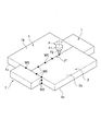
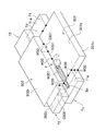
- the butting process is a process of matching the metal members 1 and 2 as shown in FIG.
- the metal members 1 and 2 are aluminum alloy plate-like members.
- the materials of the metal members 1 and 2 are appropriately selected from metals capable of friction stirring such as aluminum, aluminum alloy, copper, copper alloy, titanium, titanium alloy, magnesium, and magnesium alloy.
- the end surface 1a of the metal member 1 and the end surface 2a of the metal member 2 are butted to form a butting portion J1.
- the surfaces 1b and 2b, the back surfaces 1c and 2c, and the side surfaces 1d and 2d of the metal members 1 and 2 are flush with each other.
- the tab materials T and T are arranged at both ends of the butt portion J1.
- the surface Ta of the tab material T is flush with the surfaces 1b and 2b of the metal members 1 and 2.
- the back surface Tb of the tab material T is flush with the back surfaces 1c and 2c of the metal members 1 and 2.
- the temporary joining step is a step of temporarily joining the butt portion J1 using a rotating tool F (temporary joining rotating tool).
- the rotary tool F is made of, for example, tool steel.
- the connecting part F1 is a part connected to the rotating shaft of the friction stirrer.
- the connecting part F1 has a cylindrical shape.
- the stirring pin F2 hangs down from the connecting part F1, and is coaxial with the connecting part F1.
- the stirring pin F2 is tapered as it is separated from the connecting portion F1.
- a spiral groove is formed on the outer peripheral surface of the stirring pin F2. In the present embodiment, in order to rotate the rotary tool F to the right, the spiral groove is formed in a counterclockwise direction from the proximal end toward the distal end.
- spot welding is performed by bringing only the stirring pin F2 of the rotated rotary tool F into contact with the butting portion J1.
- only the stirring pin F2 is shallowly pushed into the butt portion J1 with a predetermined interval.
- a plasticized region W0 is formed at the trace of pushing of the stirring pin F2.
- spot tacking is also performed on the abutting portion between the metal members 1 and 2 and the tab material T, and the inner corner formed by the tab material T and the metal members 1 and 2
- spot tacking is performed, and the tab material T and the metal members 1 and 2 are temporarily joined.
- the rotary tool F is preferably attached to an arm robot having a driving unit such as a spindle unit at the tip.
- the main joining step is a step of performing the main joining to the butt joint J1 using the rotating tool F (the main joining rotating tool) as shown in FIG.
- the rotating tool F rotated to the right at the start position Sp set on one of the tab members T is inserted
- the rotating tool F is relatively moved along the abutting portion J1.
- the friction stir welding is performed in a state where only the stirring pin F2 is brought into contact with the metal members 1 and 2 and the proximal end side of the stirring pin F2 is exposed.
- a plasticizing region W1 is formed on the movement trajectory of the rotary tool F.
- the spot abutting portion J1 is temporarily attached while only the stirring pin F2 is in contact with the metal members 1 and 2, thereby acting on the friction stirrer.
- the load can be reduced.
- the process time can be shortened compared with the case where temporary joining is performed with respect to the full length of the butt
- the joining process of this embodiment is particularly effective when the total length of the butt J1 is long.
- the friction stir welding is performed with only the stirring pin F2 in contact with the metal members 1 and 2, thereby reducing the load acting on the friction stirrer and reducing the deep position of the butt J1 Can be joined.
- the same rotary tool is used for the rotary tool F (temporary joining rotary tool) that performs the temporary joining process and the rotating tool (main joining rotational tool) that performs the main joining process.
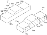
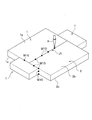
- the butting step is a step of matching the metal members 101 and 101 having the same shape, as shown in FIG.
- the metal members 101, 101 are made of an aluminum alloy in this embodiment, but may be appropriately selected from metals capable of friction stir welding.
- the metal member 101 includes a main body portion 102 that has a rectangular parallelepiped shape and a convex portion 103 that is formed on the main body portion 102 and has a trapezoidal cross section.
- the surface 103 a of the convex portion 103 is located above the surfaces 102 a and 102 b of the main body portion 102.
- the first surface 103 b of the convex part 103 is inclined and connects the surface 102 a of the main body part 102 and the surface 103 a of the convex part 103.
- the second surface 103 c of the convex portion 103 is inclined and connects the surface 102 b of the main body portion 102 and the surface 103 a of the convex portion 103.
- the metal members 101 and 101 are butted so that the surfaces thereof are flush with each other.
- the end faces 101a and 101a come into surface contact with each other in the abutting process to form the abutting portion J2.
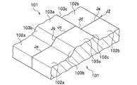
- the butting portion J2 is formed such that its height position changes. That is, in the butt portion J2, if the height (elevation) of the starting point (insertion position) of the friction stirrer is the reference height, there are sections having different reference heights and heights from the starting point to the end point.
- matching part J2 is comprised by the 1st flat part Ja, the 1st inclination part Jb, the 2nd flat part Jc, the 2nd inclination part Jd, and the 3rd flat part Je.
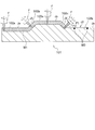
- spot tacking is performed by bringing only the stirring pin F2 of the rotating tool F (temporary joining rotating tool) into contact with the abutting portion J2, as shown in FIG.
- the temporary joining step only the agitation pin F2 rotated at a predetermined interval is shallowly pushed into the abutting portion J2.
- a plasticized region W0 is formed at the trace of pushing of the stirring pin F2.
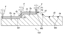
- the main joining process is a process of performing friction stir welding on the butt joint J ⁇ b> 2 using the rotary tool F (main welding rotary tool).
- the agitating pin F2 of the rotated rotating tool F is inserted into the end of the first flat portion Ja of the butting portion J2, and the rotating tool F is relatively moved along the butting portion J2.
- friction stirring is performed in a state where the rotation center axis of the rotary tool F is always parallel to the vertical axis.
- the periphery of the agitation pin F2 is frictionally agitated to join the metal members 101, 101.
- a plasticizing region W1 is formed on the movement locus of the rotary tool F.
- friction stirring is performed in a state where only the stirring pin F2 is in contact with the metal members 101, 101 while the insertion depth of the stirring pin F2 with respect to the abutting portion J2 is kept substantially constant.
- friction stirring is performed by moving the rotary tool F up and down with respect to a gantry (not shown) to which the metal members 101 and 101 are fixed.
- the “insertion depth” of the stirring pin F2 means the distance from the surface of the metal member 101 on the rotation center axis of the rotating tool F to the tip of the stirring pin F2.
- the rotary tool F is moved up and down with respect to the gantry (not shown), but the friction is caused by moving the gantry up and down while fixing the height position of the rotary tool F. Stirring may be performed.
- tab materials may be provided at both ends of the abutting portion J2, and the start position and the end position of the main joining process may be set on the tab material.
- the spot abutting portion J2 is temporarily attached while only the stirring pin F2 is in contact with the metal members 101, 101, thereby acting on the friction stirrer.
- the load can be reduced.
- the process time can be shortened compared with the case where temporary joining is performed with respect to the full length of the butt
- the temporary joining process according to the present embodiment is particularly effective when the total length of the butt portion J2 is long.
- the friction stir welding is performed in a state where only the stirring pin F2 is in contact with the metal members 101, 101, thereby reducing the load acting on the friction stirrer, and the deep position of the butt J2 Can be joined.
- the same rotary tool is used for the rotary tool F (temporary joining rotary tool) that performs the temporary joining process and the rotating tool (main joining rotational tool) that performs the main joining process.
- FIG. 8 is a cross-sectional view showing a main joining step of a modification of the friction stir welding method according to the second embodiment.
- the modification when performing the main joining process, friction stirring is performed while inserting the rotary tool F perpendicular to the joining surface.
- the rotation center axis of the rotary tool F is parallel to the vertical axis as in the second embodiment. Friction stir with.
- the rotary tool F is inclined with respect to the vertical axis, and the joint surfaces (the first surface 103b, the first surface 103b, the first inclined portion Jd, and the second inclined portion Jd). Friction stirring is performed in a state where the rotation center axis of the rotary tool F is perpendicular to the two surfaces 103c).
- the temporary joining step is a step of performing temporary joining by welding to the butt portion J1.
- the type of welding is not particularly limited.
- arc welding such as MIG welding or TIG welding or laser welding can be used.
- Laser welding is illustrated in the temporary joining process of this embodiment.
- spot tacking is performed at a predetermined interval while bringing the welding torch H close to the butt portion J1.
- a weld mark W10 is formed at the spot spot-attached portion.
- spot tacking is also performed on the abutting portion between the metal members 1 and 2 and the tab material T, and the inner corner formed by the tab material T and the metal members 1 and 2 Also, spot tacking is performed, and the tab material T and the metal members 1 and 2 are temporarily joined.
- the main joining step is a step of performing the main joining to the butt joint J1 using the rotating tool F (the main joining rotating tool) as shown in FIG.
- the rotating tool F is relatively moved along the abutting portion J1.
- the friction stir welding is performed in a state where only the stirring pin F2 is brought into contact with the metal members 1 and 2 and the proximal end side of the stirring pin F2 is exposed.
- a plasticizing region W1 is formed on the movement trajectory of the rotary tool F.
- the temporary bonding step spot bonding of the butt portion J1 is performed by welding so that temporary bonding is performed on the entire length of the butt portion J1 as in the past.
- the process time can be shortened compared with the case where it carries out.
- the temporary joining process of the present embodiment is particularly effective when the total length of the butt portion J1 is long.
- the load acting on the friction stirrer can be reduced by performing the friction stir welding with only the stirring pin in contact with the metal members 1 and 2.
- the friction stir welding is performed in a state where only the stirring pin F2 is in contact with the metal members 1 and 2, thereby reducing the load acting on the friction stirrer and reducing the deep position of the butt portion J1. Can be joined.
- a weld metal is formed at the butt portion J1.
- friction stir welding is performed in a state where the metal members 1 and 2 and the weld metal are in contact with only the stirring pin F2.
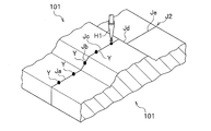
- the temporary joining step is a step of performing temporary joining by welding to the butt portion J2, as shown in FIG.
- the type of welding is not particularly limited.
- arc welding such as MIG welding or TIG welding or laser welding can be used.
- TIG welding facing welding
- spot welding is performed at a predetermined interval while supplying a filler metal (not shown) with the welding torch H1 brought close to the butt portion J1.
- the weld metal Y is formed in the spot spot-attached portion.
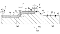
- the main joining step is a step of performing friction stir welding on the butt joint J2 using the rotary tool F (rotary tool for main joining) as shown in FIG.
- the agitating pin F2 of the rotated rotating tool F is inserted into the end of the first flat portion Ja of the butting portion J2, and the rotating tool F is relatively moved along the butting portion J2.
- friction stirring is performed in a state where the rotation center axis of the rotary tool F is always parallel to the vertical axis.
- the metal members 101 and 101 around the stirring pin F2 are frictionally stirred, and the metal members 101 and 101 are joined.
- a plasticizing region W1 is formed on the movement locus of the rotary tool F.
- the friction stir is performed in a state where only the stirring pin F2 is in contact with the metal members 101, 101 and the weld metal Y while the insertion depth of the stirring pin F2 with respect to the abutting portion J2 is kept substantially constant. I do.
- friction stirring is performed by moving the rotary tool F up and down with respect to a gantry (not shown) to which the metal members 101 and 101 are fixed.
- region W1 of the 2nd flat part Jc can be made substantially equivalent.
- the rotary tool F is moved up and down with respect to the gantry (not shown), but the friction is caused by moving the gantry up and down while fixing the height position of the rotary tool F. Stirring may be performed.
- tab materials may be provided at both ends of the abutting portion J2, and the start position and the end position of the main joining process may be set on the tab material.
- the friction stir welding method in the provisional joining step, spot joining of the butt portion J2 is performed by welding, so that provisional joining is performed on the entire length of the butt portion J2 as in the past.
- the process time can be shortened compared with the case where it carries out.
- the temporary joining process of the present embodiment is particularly effective when the total length of the butt portion J2 is long.
- the friction acting on the friction stirrer can be reduced by performing the friction stir welding with only the stirring pin in contact with the metal members 101 and 101 and the weld metal Y.
- the friction stir welding is performed in a state where only the stirring pin F2 is in contact with the metal members 101 and 101 and the weld metal Y, so that the load acting on the friction stirrer is reduced, and the butting portion J2 Can be joined in deep positions.
- FIG. 13 is a cross-sectional view showing a main joining step of a modification of the friction stir welding method according to the fourth embodiment.
- the modification when performing the main joining step, friction stirring is performed while inserting the rotary tool F perpendicular to the joining surface.
- the rotation center axis of the rotary tool F is in parallel with the vertical axis as in the third embodiment. Friction stir with.
- the rotary tool F is inclined with respect to the vertical axis, and the joint surfaces (the first surface 103b, the first surface 103b, the first inclined portion Jd, and the second inclined portion Jd). Friction stirring is performed in a state where the rotation center axis of the rotary tool F is perpendicular to the two surfaces 103c).
- the matching process is a process of matching the first metal member 201 and the second metal member 202 having different thicknesses as shown in FIG.
- the first metal member 201 and the second metal member 202 are made of aluminum alloy plate members.
- the material of the first metal member 201 and the second metal member 202 is appropriately selected from metals capable of frictional stirring such as aluminum, aluminum alloy, copper, copper alloy, titanium, titanium alloy, magnesium, and magnesium alloy.
- the second metal member 202 is thinner than the first metal member 201.
- the end surface 201a of the first metal member 201 and the end surface 202a of the second metal member 202 are butted to form a butting portion J21.
- the back surface (lower surface) 201c of the first metal member 201 and the back surface (lower surface) 202c of the second metal member 202 are flush with each other.
- the metal member 202 is positioned above the surface (upper surface) 202b.
- the side surface 201d of the first metal member 201 and the side surface 202d of the second metal member 202 are flush with each other.
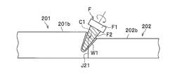
- an inner corner C ⁇ b> 1 is formed by the end surface 201 a of the first metal member 201 and the surface 202 b of the second metal member 202 at the end portion (end portion in the thickness direction of the first metal member 201) of the butting portion J ⁇ b> 21.
- the inner corner C ⁇ b> 1 extends along the edge of the surface 202 b of the second metal member 202 that abuts the end surface 201 a of the first metal member 201.
- the tab materials T and T are arranged at both ends in the extending direction of the inner corner C1.
- the surface Ta of the tab material T is flush with the surface 2b of the second metal member 202.
- the back surface Tb of the tab material T is flush with the back surface 201 c of the first metal member 201 and the back surface 202 c of the second metal member 202.
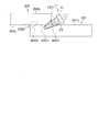
- the temporary joining step is a step of temporarily joining the inner corner C1 using the rotary tool F (temporary joining rotary tool) as shown in FIG.
- spot rotation is performed by bringing only the stirring pin F2 of the rotated rotary tool F into contact with the inner corner C1 of the end of the butting portion J21.
- only the stirring pin F2 is shallowly pushed into the butt portion J21 with a predetermined interval.
- the rotation tool F is inclined so that the stirring pin F2 does not interfere with the upper part of the end surface 201a of the first metal member 201.
- the rotary tool F is inclined so that the connecting portion F1 is on the second metal member 202 side.
- a plasticized region W0 is formed in the trace of pushing of the stirring pin F2.
- the rotary tool F is preferably attached to an arm robot (not shown) having a driving means such as a spindle unit at the tip.
- a driving means such as a spindle unit at the tip.
- spot tacking is also performed on the abutting portion between the first metal member 201 and the tab material T and the abutting portion between the second metal member 202 and the tab material T, and the tab material T
- the first metal member 201 and the second metal member 202 are temporarily joined.
- an inner corner C2 formed by the side surface 201d of the first metal member 201 and the surface Ta of the tab material T, and the first metal member 201 An inner corner C3 formed by the side surface 201d and the side surface Tc of the tab material T is formed.
- the rotation center axis of the rotary tool F is orthogonal to the surface 202 b of the second metal member 202.
- the rotary tool F is inclined so that the stirring pin F2 does not interfere with the side surface 201d of the first metal member 201 or the side surface 202d of the second metal member 202.
- the rotation tool F is inclined so that the connecting portion F1 is on the tab material T side.
- the main joining step is a step of performing the main joining with respect to the inner corner C1 of the abutting portion J21 using the rotary tool F (rotary tool for main joining) as shown in FIG.
- the rotating tool F rotary tool for main joining
- the rotating tool F is relatively moved along the inner corner C1 of the abutting portion J21.
- the friction stir welding is performed in a state where only the stirring pin F2 is brought into contact with the first metal member 201 and the second metal member 202 and the proximal end side of the stirring pin F2 is exposed.
- the rotation tool F On the tab material T, the rotation tool F is moved in a state where the rotation center axis of the rotation tool F is orthogonal to the surface Ta of the tab material T.
- the rotary tool F moves to the vicinity of the inner corner C1, the rotary tool F is inclined to the second metal member 202 side (the metal member side having a low surface).
- the inclination angle of the rotary tool F is appropriately set according to the height dimension of the step between the surface 201b of the first metal member 201 and the surface 202b of the second metal member 202. As shown in FIG.
- the rotation center axis of the rotary tool F is inclined by about 60 ° with respect to the surface 202b of the second metal member 202, and the tip of the stirring pin F2 is The metal member 201 and the second metal member 202 are not too far apart from the butting surface (the contact surface between the end surface 201a of the first metal member 201 and the end surface 202a of the second metal member 202).
- the rotation center axis of the rotary tool F is returned to a state orthogonal to the surface Ta of the tab member T.
- the rotary tool F reaches the end position Ep set on the other tab material T, the rotary tool F is detached from the tab material T.
- the plasticized region W1 is formed in the movement locus of the rotary tool F.
- the plasticized region W1 can be formed around the stirring pin F2 in a well-balanced manner. it can. Further, the inclination angle of the rotary tool F is set according to the height dimension of the step. The inclination angle is set so that the tip of the stirring pin F ⁇ b> 2 is not too far from the abutting surface between the first metal member 201 and the second metal member 202. As a result, the plasticized region W1 is formed over a wide range of the butted surfaces, so that the bonding strength can be increased.
- the same rotary tool is used for the rotary tool F (temporary joining rotary tool) that performs the temporary joining process and the rotational tool (main joining rotational tool) that performs the main joining process.
- the first metal member 201 and the second metal member 202 having different thicknesses are abutted to form the inner corner C1, but the end of the first metal member and the second metal member having the same thickness are formed.
- the inner corner may be formed by offsetting and matching the end of the inner corner.
- the superimposing step is a step of superposing the first metal member 301 and the second metal member 302 as shown in FIG.
- the first metal member 301 and the second metal member 302 are made of aluminum alloy plate members.
- the material of the first metal member 301 and the second metal member 302 is appropriately selected from metals capable of friction stirring such as aluminum, aluminum alloy, copper, copper alloy, titanium, titanium alloy, magnesium, and magnesium alloy.
- the thickness dimension of the first metal member 301 is the same as the thickness dimension of the second metal member 302.
- the thickness dimension of the first metal member 301 and the thickness dimension of the second metal member 302 may be different.
- the overlap portion K301 is formed by superimposing the front surface 301b of the first metal member 301 and the back surface 302c of the second metal member 302.
- the surface 301b of the first metal member 301 and the end surface 302a of the second metal member 302 are The inner corner C301 is formed.
- the front inner corner C301 extends along the lower edge of the end surface 302a of the second metal member 302 that intersects the surface 301b of the first metal member 301.
- the end surface 301a of the first metal member 301 and the second metal are disposed at the other end of the overlapping portion K301 (the end portion on the end surface 301a side of the first metal member 301 in the direction orthogonal to the end surface 302a of the second metal member 302).
- a back inner corner C302 is formed with the back surface 302c of the member 302. The back inner corner C302 extends along the upper edge of the end surface 301a of the first metal member 301 that intersects the back surface 302c of the second metal member 302.
- the tab materials T1 and T1 are arranged at both ends in the extending direction of the front corner C301.
- the tab material T1 is brought into contact with the side surface 301d of the first metal member 301.
- the surface T1a of the tab material T1 is flush with the surface 301b of the first metal member 301 and the back surface 302c of the second metal member 302.
- the back surface T1b of the tab material T1 is flush with the back surface 301c of the first metal member 301.
- the tab materials T2 and T2 are disposed at both ends in the extending direction of the back inner corner C302.
- the tab material T2 is brought into contact with the side surface 302d of the second metal member 302.
- the surface T2a of the tab material T2 is flush with the surface 302b of the second metal member 302. Further, the back surface T2b of the tab material T1 is flush with the front surface 301b of the first metal member 301 and the back surface 302c of the second metal member 302.
- the temporary joining step is a step of temporarily joining the front inner corner C301 and the back inner corner C302 using a rotary tool F (temporary joining rotary tool) as shown in FIG.
- the rotary tool F is the same as that of the fifth embodiment, and is attached to an arm robot (not shown) having a driving means such as a spindle unit at the tip.
- spot rotation is performed by bringing only the stirring pin F2 of the rotated rotary tool F into contact with the front inner corner C301 and the rear inner corner C302.
- only the stirring pin F2 is shallowly pushed into the overlapping portion K301 with a predetermined interval.
- the rotary tool F is inclined so that the connecting portion F1 is on the first metal member 301 side.
- a plasticized region W0 is formed in the trace of pushing of the stirring pin F2.
- spot tacking is also performed on the abutting portion between the first metal member 301 and the tab material T1 and the abutting portion between the second metal member 302 and the tab material T2, and the tab materials T1, T2
- the first metal member 301 and the second metal member 302 are temporarily joined.
- An inner corner C304 formed by the side surface 301d and the side surface T1c of the tab material T1, and a part of the surface formed by the surface 301b of the first metal member 301 and the surface T1a of the tab material T1 are formed.
- the rotation center axis of the rotary tool F is orthogonal to the surface 301 b of the first metal member 301.
- the rotary tool F When spotting the inner corners C303 and C304, the rotary tool F is inclined so that the stirring pin F2 does not interfere with the first metal member 301, the second metal member 302, and the tab material T1.
- the rotary tool F is inclined so that the connecting portion F1 is on the tab material T1 side.
- An inner corner C306 formed by the side surface 302d and the side surface T2c of the tab material T2, and a part of the surface formed by the back surface 302c of the second metal member 302 and the back surface T2b of the tab material T2 are formed.
- the rotation center axis of the rotary tool F is orthogonal to the back surface 302 c of the second metal member 302.
- the rotary tool F When spotting the inner corners C305 and C306, the rotary tool F is inclined so that the stirring pin F2 does not interfere with the first metal member 301, the second metal member 302, and the tab material T2.
- the rotation tool F is inclined so that the connecting portion F1 is on the tab material T2 side.
- the main joining step is a step of performing main joining to the front inner corner C301 and the back inner corner C302 of the overlapping portion K301 by using the rotary tool F (main welding rotary tool).
- the main joining of the front inner corner C301 is performed.
- the rotation tool F is relatively moved along the inner corner C301.
- the friction stir welding is performed in a state where only the stirring pin F2 is brought into contact with the first metal member 301 and the second metal member 302 and the proximal end side of the stirring pin F2 is exposed.
- the rotation tool F On the tab material T1, the rotation tool F is moved in a state where the rotation center axis of the rotation tool F is orthogonal to the surface T1a of the tab material T1.
- the rotary tool F moves to the vicinity of the front inner corner C301, the rotary tool F is inclined to the first metal member 301 side (lower metal member side).
- the inclination angle of the rotary tool F is appropriately set according to the shape of the rotary tool F.
- the connecting portion F ⁇ b> 1 of the rotary tool F is inclined toward the first metal member 301 as long as it does not interfere with the first metal member 301.
- the rotation center axis of the rotary tool F is inclined by about 30 ° with respect to the surface 301b of the first metal member 301, and the tip of the stirring pin F2 is formed between the first metal member 301 and the second metal.
- the overlapping surface with the member 302 (the contact surface between the front surface 301b of the first metal member 301 and the back surface 302c of the second metal member 302) is not too far away.
- the first metal member 301, the second metal member 302, and the tab materials T1, T2 are turned upside down, and the main joining is performed to the back inner corner C302.
- the rotation tool F is relatively moved along the back inner corner C302, and the other The rotary tool F is detached from the end position set on the tab material T2.
- the inclination angle and insertion depth of the rotating tool F in the middle are equivalent to the main joining of the front inner corner C301.
- a plasticized region W302 (indicated by a two-dot chain line in FIG. 21) is formed on the movement locus of the rotary tool F. Note that if the bottom of the plasticized region W301 formed in the front inner corner C301 overlaps the bottom of the plasticized region W302 formed in the back inner corner C302, the bonding strength is further increased.
- the front inner corner C301 and the inner back of the overlapping portion K301 in a state where only the stirring pin F2 is in contact with the first metal member 301 and the second metal member 302.
- the load acting on the friction stirrer can be reduced.
- process time can be shortened compared with the case where temporary joining is performed with respect to the full length of the superposition
- the joining process of this embodiment is particularly effective when the total length of the front inner corner C301 and the back inner corner C302 of the overlapping portion K301 is long.
- the load acting on the friction stirrer is reduced. A deep position of the overlapping portion K301 can be joined.
- the plasticized region W302. can be formed around the stirring pin F2 in a well-balanced manner.
- the inclination angle of the rotary tool F is set according to the shape of the rotary tool F. The inclination angle is set so that the tip of the stirring pin F ⁇ b> 2 is not too far from the overlapping surface of the first metal member 301 and the second metal member 302. As a result, the plasticized regions W301 and W302 are formed over a wide range of the overlapping surface, so that the bonding strength can be increased.
- the same rotary tool is used for the rotary tool F (temporary joining rotary tool) that performs the temporary joining process and the rotational tool (main joining rotational tool) that performs the main joining process.
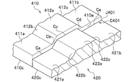
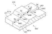
- the matching process is a process of matching the first metal member 410 and the second metal member 420 having different thicknesses as shown in FIG.
- the first metal member 410 and the second metal member 420 are made of an aluminum alloy in this embodiment, but may be appropriately selected from metals capable of friction stir welding.
- the 1st metal member 410 is comprised by the main-body part 411 which exhibits a rectangular parallelepiped, and the convex part 412 which is formed on the main-body part 411 and exhibits a cross-sectional trapezoid shape.
- the convex portion 412 is disposed in the middle of the main body portion 411.
- the upper surface 412a of the convex portion 412 is located above the surfaces 411a and 411b of the main body portion 411.
- the first inclined surface 412 b of the convex portion 412 is a portion corresponding to a trapezoidal hypotenuse and connects the surface 411 a of the main body portion 411 and the upper surface 412 a of the convex portion 412.
- the second surface 412c of the convex portion 412 is a portion corresponding to a trapezoidal hypotenuse and connects the surface 411b of the main body portion 411 and the upper surface 412a of the convex portion 412.
- the second metal member 420 includes a main body portion 421 that has a rectangular parallelepiped shape and a convex portion 422 that is formed on the main body portion 421 and has a trapezoidal cross section.
- the convex part 422 is arranged in the middle of the main body part 421.
- the thickness of the main body 421 of the second metal member 420 is thinner than the thickness of the main body 411 of the first metal member 410.
- the shape of the convex portion 422 is the same as that of the convex portion 412.
- the upper surface 422a of the convex part 422 is located above the surfaces 421a and 421b of the main body part 421.
- the first inclined surface 422b of the convex portion 422 is a portion corresponding to a trapezoidal hypotenuse and connects the surface 421a of the main body portion 421 and the upper surface 422a of the convex portion 422.
- the second surface 422c of the convex part 422 is a part corresponding to a trapezoidal hypotenuse and connects the surface 421b of the main body part 421 and the upper surface 422a of the convex part 422.
- the end surface 410a of the first metal member 410 and the end surface 420a of the second metal member 420 are butted.
- the back surface (lower surface) 410c of the first metal member 410 and the back surface (lower surface) 420c of the second metal member 420 are flush with each other, and thus each surface (upper surface) 411a of the main body portion 411 of the first metal member 410.
- 411b are located above the respective surfaces (upper surfaces) 421a, 421b of the main body 421 of the second metal member 420.
- each surface (upper surface) 412a, 412b, 412c of the convex part 412 of the first metal member 410 is respectively higher than each surface (upper surface) 422a, 422b, 422c of the corresponding convex part 422 of the second metal member 420. positioned.
- the end faces 410a and 420a are brought into surface contact with each other in the abutting process to form the abutting portion J401.
- Butt portion J401 is formed such that its height position changes.
- the end surface 410a of the first metal member 410 and the respective surfaces 421a, 422b, 422a, 422c, 421b of the second metal member 420
- An inner corner C401 is formed.
- the inner corner C401 when the height (elevation) of the starting point (insertion position) of friction stirring is a reference height, there are sections having different reference heights and heights from the starting point to the end point.
- the inner corner C401 includes a first flat portion Ca, a first inclined portion Cb, a second flat portion Cc, a second inclined portion Cd, and a third flat portion Ce.
- the insertion position is in the first flat portion Ca.
- spot tacking is performed by bringing only the stirring pin F2 of the rotating tool F (temporary joining rotating tool) into contact with the inner corner C401 of the abutting portion J401 as shown in FIG.
- the temporary joining step only the stirring pin F2 rotated at a predetermined interval is shallowly pushed into each part of the inner corner C401.
- a plasticized region W0 is formed at the trace of pushing of the stirring pin F2.
- the rotation tool F is inclined so that the stirring pin F2 does not interfere with the upper part of the end surface 410a of the first metal member 410.
- the rotary tool F is inclined so that the connecting portion F1 is on the second metal member 420 side.
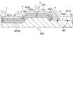
- the main joining step is a step of performing friction stir welding with respect to the inner corner C401 of the abutting portion J401 using the rotating tool F (rotating tool for main joining) as shown in FIG.
- the stirring pin F2 of the rotated tool F is inserted into the end of the first flat portion Ca of the inner corner C401, and the rotating tool F is relatively moved along the inner corner C401.
- the rotary tool F is inclined to the second metal member 420 side (metal member side having a low surface). The inclination angle of the rotary tool F is appropriately set according to the height of the step between the surface 411a of the first metal member 410 and the surface 421a of the second metal member 420.
- the rotation center axis of the rotary tool F is orthogonal to the traveling direction of the rotary tool F on the surface 421a of the main body 421.
- the rotary tool F performs friction stirring while maintaining this angle.
- the periphery of the agitating pin F2 is frictionally agitated, and the first metal member 410 and the second metal member 420 are joined.
- a plasticizing region W401 is formed on the movement locus of the rotary tool F.
- Friction stir is performed in the state of being allowed to stand.
- friction stirring is performed by moving the rotary tool F up and down with respect to a gantry (not shown) to which the first metal member 410 and the second metal member 420 are fixed.
- the rotary tool F is moved up and down with respect to the gantry (not shown), but the friction is caused by moving the gantry up and down while fixing the height position of the rotary tool F. Stirring may be performed.
- tab materials may be provided at both ends of the inner corner C401, and the start position and the end position of the main joining process may be set on the tab material.
- spot tacking of the inner corner C401 of the abutting portion J401 is performed with only the stirring pin F2 in contact with the first metal member 410 and the second metal member 420.
- the load acting on the friction stirrer can be reduced.
- the process time can be shortened compared with the case where temporary joining is performed with respect to the full length of the butt
- the temporary joining process according to the present embodiment is particularly effective when the total length of the butt portion J401 is long.
- by performing friction stir welding with only the stirring pin F2 in contact with the first metal member 410 and the second metal member 420 the load acting on the friction stirrer is reduced, A deep position of the butt J401 can be joined.
- the same rotary tool is used for the rotary tool F (temporary joining rotary tool) that performs the temporary joining process and the rotating tool (main joining rotational tool) that performs the main joining process.
- FIG. 26 is a cross-sectional view showing the main joining step of a modification of the friction stir welding method according to the seventh embodiment.
- the rotational axis of the rotary tool F is inserted while being perpendicular to the inner corner line (line extending along the inner corner C401).
- the rotary tool F is placed on the second metal member 420 side (the surface is low) as in the seventh embodiment. Tilt to the metal member side. That is, the rotary tool F is made to stand upright with respect to the surface 421a of the second metal member 420 when the rotary tool F is viewed from the side of the second metal member 420 (in the state shown in FIG. 26).
- the rotation tool F is made from the 2nd metal member 420 side. Inclined even when viewed from the side. Specifically, when the rotary tool F is viewed from the side of the second metal member 420, the rotary tool F is inclined to the surfaces 422 b and 422 c of the convex portions 422 of the second metal member 420 and the first metal member 410. It is made to stand upright with respect to each inner corner line constituted by the end face of each. Friction stirring is performed in the above state.
- the rotary tool F can be inserted perpendicularly to each inner corner line, even with an inclined surface, friction stirring can be performed up to a deep position of the inner corner C401 of the abutting portion J401.
- the friction stir may be performed while overlapping the vertical surface with respect to each inner corner line and the rotation center axis of the rotary tool F when viewed from the second metal member 420 side.
- the temporary joining step is a step of temporarily joining the inner corner C1 by welding as shown in FIG.
- the type of welding is not particularly limited.
- arc welding such as MIG welding or TIG welding or laser welding can be used.
- Laser welding is illustrated in the temporary joining process of this embodiment.
- spot tacking is performed at a predetermined interval while bringing the welding torch H close to the inner corner C1.
- the upper part of the welding torch H is inclined toward the second metal member 202 so that the tip of the welding torch H faces the inner corner C1.
- a weld mark W20 is formed in the spot spot-attached portion.
- temporary bonding is also performed by spot welding on the butted portion between the first metal member 201 and the tab material T and the butted portion between the second metal member 202 and the tab material T.
- the first metal member 201 and the second metal member 202 are temporarily joined.
- an inner corner C2 formed by the side surface 201d of the first metal member 201 and the surface Ta of the tab material T, and the first metal member 201 An inner corner C3 formed by the side surface 201d and the side surface Tc of the tab material T is formed.
- the welding torch H is orthogonal to the surface 202 b of the second metal member 202.
- the welding torch H is inclined so that the tip of the welding torch H faces the inner corners C2, C3, and C4, respectively.
- the main joining step is a step of performing the main joining to the inner corner C1 of the butt joint J21 using the rotary tool F as shown in FIG.
- the rotating tool F rotated to the right at the start position Sp set on one of the tab members T is inserted, the rotating tool F is relatively moved along the inner corner C1 of the butt portion J21.
- the friction stir welding is performed in a state where only the stirring pin F2 is brought into contact with the first metal member 201 and the second metal member 202 and the proximal end side of the stirring pin F2 is exposed.
- the rotation tool F is moved in a state where the rotation center axis of the rotation tool F is orthogonal to the surface Ta of the tab material T.
- the rotary tool F moves to the vicinity of the inner corner C1
- the rotary tool F is inclined to the second metal member 202 side (the metal member side having a low surface).
- the inclination angle of the rotary tool F is appropriately set according to the height dimension of the step between the surface 201b of the first metal member 201 and the surface 202b of the second metal member 202. As shown in FIG.
- the rotation center axis of the rotary tool F is inclined by about 60 ° with respect to the surface 202b of the second metal member 202, and the tip of the stirring pin F2 is The metal member 201 and the second metal member 202 are not too far apart from the butting surface (the contact surface between the end surface 201a of the first metal member 201 and the end surface 202a of the second metal member 202).
- the rotation center axis of the rotary tool F returns to a state orthogonal to the surface Ta of the tab member T.
- the rotary tool F reaches the end position Ep set on the other tab material T, the rotary tool F is detached from the tab material T.
- the friction stirrer by performing spot tacking of the inner corner C1 of the butt portion J21 by laser welding, the friction stirrer is more effective than when performing tacking by friction stirring.
- the burden that acts on the can be reduced.
- the process time can be shortened as compared with the conventional case where temporary joining is performed on the entire length of the inner corner C1 of the butt portion J21.
- the joining process of this embodiment is particularly effective when the total length of the inner corner C1 is long.
- this bonding step by performing friction stir welding with only the stirring pin F2 in contact with the first metal member 201 and the second metal member 202, the load acting on the friction stirrer is reduced, A deep position of the butt J21 can be joined.
- the plasticized region W1 can be formed around the stirring pin F2 in a well-balanced manner. it can. Further, the inclination angle of the rotary tool F is set according to the height dimension of the step. The inclination angle is set so that the tip of the stirring pin F ⁇ b> 2 is not too far from the abutting surface between the first metal member 201 and the second metal member 202. As a result, the plasticized region W1 is formed over a wide range of the butted surfaces, so that the bonding strength can be increased.
- a rotating tool including a shoulder portion and a stirring pin may be used as the rotating tool F.
- this main joining process was performed only from the surface 201b of the 1st metal member 201 and the surface 202b side of the 2nd metal member 202, you may perform from the back surfaces 201c and 202c side.
- the plasticized region W1 formed on the front surfaces 201b and 202b overlaps with the plasticized region (not shown) formed on the back surfaces 201c and 202c, the bonding strength of the butt joint J21 is increased. Can do.
- the first metal member 201 and the second metal member 202 having different thicknesses are abutted to form the inner corner C1, but the end of the first metal member and the second metal member having the same thickness are formed.
- the inner corner may be formed by offsetting and matching the end of the inner corner.
- the temporary joining step is a step of temporarily joining the front inner corner C301 and the rear inner corner C302 by welding as shown in FIG.
- the type of welding is not particularly limited.
- arc welding such as MIG welding or TIG welding or laser welding can be used.
- Laser welding is illustrated in the temporary joining process of this embodiment.
- spot tacking is performed at predetermined intervals while the welding torch H is brought close to the front inner corner C301 and the rear inner corner C302. At this time, the upper part of the welding torch H is inclined so that the front end of the welding torch H faces the front inner corner C301 and the rear inner corner C302. A weld mark W30 is formed in the spot spot-attached portion.
- temporary bonding is performed by spot welding to the butted portion between the first metal member 301 and the tab material T1 and the butted portion between the second metal member 302 and the tab material T2, and the tab materials T1 and T2 are bonded.
- the first metal member 301 and the second metal member 302 are temporarily joined.
- An inner corner C304 formed by the side surface 301d and the side surface T1c of the tab material T1, and a part of the surface formed by the surface 301b of the first metal member 301 and the surface T1a of the tab material T1 are formed.
- the welding torch H is orthogonal to the surface 301 b of the first metal member 301.
- the welding torch H is inclined so that the tip of the welding torch H faces the inner corners C303 and C304, respectively.
- An inner corner C306 formed by the side surface 302d and the side surface T2c of the tab material T2, and a part of the surface formed by the back surface 302c of the second metal member 302 and the back surface T2b of the tab material T2 are formed.
- the welding torch H is orthogonal to the back surface 302 c of the second metal member 302.
- the welding torch H is inclined so that the tip of the welding torch H faces the inner corners C305 and C306, respectively.
- the main joining step is a step of performing main joining to the front inner corner C301 and the back inner corner C302 of the overlapping portion K301 using the rotary tool F as shown in FIG.
- the main joining of the front inner corner C301 is performed.
- the rotation tool F is relatively moved along the inner corner C301.
- the friction stir welding is performed in a state where only the stirring pin F2 is brought into contact with the first metal member 301 and the second metal member 302 and the proximal end side of the stirring pin F2 is exposed.
- the rotation tool F On the tab material T1, the rotation tool F is moved in a state where the rotation center axis of the rotation tool F is orthogonal to the surface T1a of the tab material T1.
- the rotary tool F moves to the vicinity of the front inner corner C301, the rotary tool F is inclined to the first metal member 301 side (lower metal member side).
- the inclination angle of the rotary tool F is appropriately set according to the shape of the rotary tool F.
- the connecting portion F ⁇ b> 1 of the rotary tool F is inclined toward the first metal member 301 as long as it does not interfere with the first metal member 301.
- the rotation center axis of the rotary tool F is inclined by about 30 ° with respect to the surface 301b of the first metal member 301, and the tip of the stirring pin F2 is formed between the first metal member 301 and the second metal.
- the overlapping surface with the member 302 (the contact surface between the front surface 301b of the first metal member 301 and the back surface 302c of the second metal member 302) is not too far away.
- the first metal member 301, the second metal member 302, and the tab materials T1, T2 are turned upside down, and the main joining is performed to the back inner corner C302.
- the rotation tool F is relatively moved along the back inner corner C302, and the other The rotary tool F is detached from the end position set on the tab material T2.
- the inclination angle and insertion depth of the rotating tool F in the middle are equivalent to the main joining of the front inner corner C301.
- a plasticized region W302 (indicated by a two-dot chain line in FIG. 32) is formed on the movement locus of the rotary tool F. Note that if the bottom of the plasticized region W301 formed in the front inner corner C301 overlaps the bottom of the plasticized region W302 formed in the back inner corner C302, the bonding strength is further increased.
- the tacking is performed by friction stir by performing spot tacking of the front inner corner C301 and the back inner corner C302 of the overlapping portion K301 by laser welding.
- the burden on the friction stirrer can be reduced.
- process time can be shortened compared with the case where it temporarily joins with respect to the full length of a superposition
- the joining process of this embodiment is particularly effective when the total length of the front inner corner C301 and the back inner corner C302 of the overlapping portion K301 is long.
- by performing friction stir welding with only the stirring pin F2 in contact with the first metal member 301 and the second metal member 302, the load acting on the friction stirrer is reduced. A deep position of the overlapping portion K301 can be joined.
- the plasticized region W301. , W302 can be formed around the stirring pin F2 in a well-balanced manner.
- the inclination angle of the rotary tool F is set according to the shape of the rotary tool F. The inclination angle is set so that the tip of the stirring pin F ⁇ b> 2 is not too far from the overlapping surface of the first metal member 301 and the second metal member 302. As a result, the plasticized regions W301 and W302 are formed over a wide range of the overlapping surface, so that the bonding strength can be increased.
- spot tacking is performed by welding on the inner corner C401 of the butt J401 as shown in FIG.
- the type of welding is not particularly limited.
- arc welding such as MIG welding or TIG welding or laser welding can be used.
- Laser welding is illustrated in the temporary joining process of this embodiment.
- spot tacking is performed at a predetermined interval while bringing the welding torch H close to the inner corner C401. At this time, the upper part of the welding torch H is inclined toward the second metal member 420 so that the tip of the welding torch H faces the inner corner C401.
- a weld mark W40 is formed at the spot spot-attached portion.
- the main joining step is a step of performing friction stir welding to the inner corner C401 of the butt joint J401 using the rotary tool F as shown in FIG.
- the stirring pin F2 of the rotated tool F is inserted into the end of the first flat portion Ca of the inner corner C401, and the rotating tool F is relatively moved along the inner corner C401.
- the rotary tool F is inclined to the second metal member 420 side (metal member side having a low surface).
- the inclination angle of the rotary tool F is appropriately set according to the height of the step between the surface 411a of the first metal member 410 and the surface 421a of the second metal member 420.
- the rotation center axis of the rotary tool F is orthogonal to the traveling direction of the rotary tool F on the surface 421a of the main body 421.
- the rotary tool F performs friction stirring while maintaining this angle.
- the periphery of the agitating pin F2 is frictionally agitated, and the first metal member 410 and the second metal member 420 are joined.
- a plasticizing region W401 is formed on the movement locus of the rotary tool F.
- Friction stir is performed in the state of being allowed to stand.
- friction stirring is performed by moving the rotary tool F up and down with respect to a gantry (not shown) to which the first metal member 410 and the second metal member 420 are fixed.
- the “insertion depth” of the stirring pin F2 means the distance from the surface of the second metal member 420 on the rotation center axis of the rotary tool F to the tip of the stirring pin F2.
- the rotary tool F is moved up and down with respect to the gantry (not shown), but the friction is caused by moving the gantry up and down while fixing the height position of the rotary tool F. Stirring may be performed.
- tab materials may be provided at both ends of the inner corner C401, and the start position and the end position of the main joining process may be set on the tab material.
- the friction stirrer by performing spot tacking of the inner corner C401 of the butt portion J401 by laser welding, the friction stirrer can be used in comparison with the case where tacking is performed by friction stirring.
- the burden of acting can be reduced.
- process time can be shortened compared with the case where temporary joining is performed with respect to the full length of the butt
- the temporary joining process according to the present embodiment is particularly effective when the total length of the butt portion J401 is long.
- the load acting on the friction stirrer is reduced, A deep position of the butt J401 can be joined.
- a rotating tool including a shoulder portion and a stirring pin may be used as the rotating tool F.
- different rotary tools may be used in the temporary joining step and the main joining step.
- FIG. 35 is a cross-sectional view showing a main joining step of a modification of the friction stir welding method according to the tenth embodiment.
- the rotation axis of the rotary tool F is frictionally inserted perpendicularly to the inner corner line (line extending along the inner corner C401).
- the rotary tool F is placed on the second metal member 420 side (the surface is low) as in the tenth embodiment. Tilt to the metal member side. That is, the rotary tool F is made to stand upright with respect to the surface 421a of the second metal member 420 when the rotary tool F is viewed from the side of the second metal member 420 (in the state shown in FIG. 35).
- the rotation tool F is made from the 2nd metal member 420 side. Inclined even when viewed from the side. Specifically, when the rotary tool F is viewed from the side of the second metal member 420, the rotary tool F is inclined to the surfaces 422 b and 422 c of the convex portions 422 of the second metal member 420 and the first metal member 410. It is made to stand upright with respect to each inner corner line constituted by the end face of each. Friction stirring is performed in the above state.
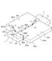
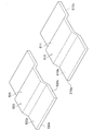
- the overlapping step is a step of overlapping the first metal member 510 and the second metal member 520 as shown in FIGS.
- the first metal member 510 and the second metal member 520 are made of aluminum alloy plate members.
- the material of the first metal member 510 and the second metal member 520 is appropriately selected from metals capable of friction stirring such as aluminum, aluminum alloy, copper, copper alloy, titanium, titanium alloy, magnesium, magnesium alloy, and the like.
- the thickness dimension of the first metal member 510 is the same as the thickness dimension of the second metal member 520.
- the thickness dimension of the first metal member 510 and the thickness dimension of the second metal member 520 may be different.
- the intermediate portion 511 of the front surface 510b of the first metal member 510 has a convex shape
- the intermediate portion 511 of the back surface 510c of the first metal member 510 has a concave shape.
- the intermediate portion 511 of the first metal member 510 is formed in a trapezoidal shape when viewed from the front.
- the height of the intermediate portion 521 of the surface 520b of the second metal member 520 changes in a convex shape
- the height of the intermediate portion 521 of the back surface 520c of the second metal member 520 changes in a concave shape.
- the intermediate part 521 of the second metal member 520 is formed in a trapezoidal shape when viewed from the front.
- the intermediate part 511 of the first metal member 510 and the intermediate part 521 of the second metal member 520 have the same shape.
- the surface 510b of the first metal member 510 and the back surface 520c of the second metal member 520 are overlapped to form the overlapping portion K1.
- a front inner corner C510 is formed by the surface 510b of the first metal member 510 and the end surface 520a of the second metal member 520.
- the front inner corner C510 extends along the lower end edge of the end surface 520a of the second metal member 520 that intersects the surface 510b of the first metal member 510.
- a back inner corner C520 is formed in the overlapping portion K1 by the end surface 510a of the first metal member 510 and the back surface 520c of the second metal member 520.
- the back inner corner C520 extends along the upper edge of the end surface 510a of the first metal member 510 that intersects the back surface 520c of the second metal member 520.
- the overlapping portion K1 is formed such that its height position changes on the front surface side and the back surface side.
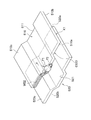
- the temporary joining step is a step of temporarily joining the inner corner C510 with the rotary tool F (temporary joining rotary tool).
- the rotary tool F is attached to an arm robot (not shown) having a driving unit such as a spindle unit at the tip.
- spot welding is performed by bringing only the stirring pin F2 of the rotated rotary tool F into contact with the inner corner C510.
- only the stirring pin F2 is shallowly pushed into the overlapping portion K1 with a predetermined interval.
- the rotary tool F is inclined so that the connecting portion F1 is on the first metal member 510 side.
- a plasticized region W50 is formed at the trace of pushing of the stirring pin F2.
- the main joining step is a step of performing the main joining to the front inner corner C510 and the back inner corner C520 of the overlapping portion K1 using the rotary tool F (main welding rotary tool). It is.
- the main joining of the front inner corner C510 is first performed.
- the rotated rotary tool F is inserted into one end of the front inner corner C510, and the rotary tool F is relatively moved along the front inner corner C510.
- friction stir welding is performed with only the stirring pin F2 in contact with the first metal member 510 and the second metal member 520 and the base end side of the stirring pin F2 is exposed.
- the tip portion of the stirring pin F2 is a superposed surface of the first metal member 510 and the second metal member 520. Do not be too far away from the contact surface between the front surface 510b of the first metal member 510 and the back surface 520c of the second metal member 520. In this way, when the rotary tool F is moved from one end of the front inner corner C510 to the other end, a plasticized region W51 is formed on the movement trajectory of the rotary tool F.
- the first metal member 510 and the second metal member 520 are turned upside down to perform the main joining to the back inner corner C520.
- the rotated rotating tool F is inserted into one end of the back inner corner C520, and the rotating tool F is inclined to the second metal member 520 side (the lower metal member side).
- the rotary tool F is moved from one end of the inner corner C520 to the other end.
- the inclination angle and insertion depth of the rotating tool F on the way are the same as the main joining at the front inner corner C510.
- a plasticizing region W52 is formed on the movement locus of the rotary tool F.
- the bottom of the plasticized region W51 formed in the front inner corner C510 (see FIG. 38) and the bottom of the plasticized region W52 formed in the back inner corner C520 are provided. You may overlap. Thereby, joint strength can be raised further.
- the overlapping portion K1 with only the stirring pin F2 in contact with the first metal member 510 and the second metal member 520 By performing the spot tacking of the inner corner C510, the load acting on the friction stirrer can be reduced. Moreover, process time can be shortened compared with the case where temporary joining is performed with respect to the full length of the superposition
- the temporary joining process of the present embodiment is particularly effective when the total length of the front inner corner C510 of the overlapping portion K1 is long. Further, also in the main joining step, as shown in FIGS.
- the friction stir welding apparatus performs the friction stir welding with only the stirring pin in contact with the first metal member 510 and the second metal member 520.
- a deep position of the overlapping portion K1 can be joined in a state where the load acting on the surface is reduced.
- the head of the rotary tool F when the front inner corner C510 is finally joined, the head of the rotary tool F is inclined toward the surface 510b of the first metal member 510 that is the bottom side of the step. Further, when the back inner corner C520 is finally joined, the head of the rotary tool F is inclined toward the back surface 520c of the second metal member 520 that is the bottom side of the step.
- regions W51 and W52 can be formed with sufficient balance around the stirring pin F2.
- the tip end portion of the stirring pin F2 is the overlapping surface of the first metal member 510 and the second metal member 520. Not too far from As a result, the plasticized regions W51 and W52 are formed over a wide range of the polymerization surface, so that the bonding strength can be increased.
- the same rotary tool is used for the rotary tool F (temporary joining rotary tool) that performs the temporary joining process and the rotating tool (main joining rotational tool) that performs the main joining process.
- the friction tool can be continuously stirred while the rotary tool F is always perpendicular to the inner corner line. Good.
- friction stirring can be performed to a deep position of the overlapping portion K1 even on an inclined surface.
- the main bonding is performed with respect to the front inner corner C510 and the back inner corner C520, but the main bonding may be performed only on the front inner corner C510.
- temporary bonding is performed only on the front inner corner C510, but temporary bonding may also be performed on the back inner corner C520 (see FIG. 39). Alternatively, temporary bonding may be performed only on the back inner corner C520.
- the rotary tool F is used to temporarily join the inner corner C510.
- the welding torch H is used.
- spot tacking may be performed on the inner corner C510.
- temporary joining may be performed on the inner corner C510 by arc welding such as MIG welding or TIG welding or laser welding.
- a welding mark W53 is formed at the welding location.
- the heights of the front surface 510b and the back surface 510c of the first metal member 510 are changed, and the heights of the front surface 520b and the back surface 520c of the second metal member 520 are changed.
- the member 510 may be formed such that only the height of the front surface 510b changes, and the second metal member 520 may change only the height of the back surface 520c.
Landscapes
- Engineering & Computer Science (AREA)
- Mechanical Engineering (AREA)
- Pressure Welding/Diffusion-Bonding (AREA)
Abstract
摩擦攪拌装置に作用する負荷を軽減することができる摩擦攪拌接合方法を提供することを課題とする。金属部材(1,2)を接合する摩擦攪拌接合方法であって、金属部材(1,2)の突合せ部(J1)に回転した回転ツール(仮接合用回転ツール)(F)の攪拌ピン(F2)を挿入し、攪拌ピン(F2)のみを金属部材(1,2)に接触させた状態でスポット仮付けを行う仮接合工程と、突合せ部(J1)に回転した回転ツール(本接合用回転ツール)(F)の攪拌ピン(F2)を挿入し、攪拌ピン(F2)のみを金属部材(1,2)に接触させた状態で突合せ部(J1)に沿って相対移動させて摩擦攪拌接合を行う本接合工程と、を含むことを特徴とする。
Description
本発明は、摩擦攪拌接合方法に関する。
特許文献1には、金属部材同士が突き合わされた突合せ部に対して、小型の回転ツールで仮接合工程を行った後、大型の回転ツールで本接合工程を行う摩擦攪拌接合方法が記載されている。仮接合工程を行うことにより、本接合工程の際に、突合せ部の目開きを防ぐことができる。
当該摩擦攪拌接合方法の仮接合工程は、小型の回転ツールのショルダ部を数ミリ程度金属部材に押し込んで接合するというものである。当該接合方法であると、ショルダ部を金属部材に押し込むため摩擦攪拌装置に作用する負荷が大きくなるという問題がある。
そこで、本発明は、摩擦攪拌装置に作用する負荷を軽減することができる摩擦攪拌接合方法を提供することを課題とする。
このような課題を解決するために本発明は、二つの金属部材を接合する摩擦攪拌接合方法であって、前記金属部材の突合せ部に回転した仮接合用回転ツールの攪拌ピンを挿入し、前記攪拌ピンのみを前記金属部材に接触させた状態でスポット仮付けを行う仮接合工程と、前記突合せ部に回転した本接合用回転ツールの攪拌ピンを挿入し、前記攪拌ピンのみを前記金属部材に接触させた状態で前記突合せ部に沿って相対移動させて摩擦攪拌接合を行う本接合工程と、を含むことを特徴とする。
また、本発明は、表面の高さが変化する金属部材同士を突き合わせて高さが変化する突合せ部を形成する突合せ工程と、高さが変化する前記突合せ部に対して回転した仮接合用回転ツールの攪拌ピンを挿入し、前記攪拌ピンのみを前記金属部材に接触させた状態でスポット仮付けを行う仮接合工程と、前記突合せ部に回転した本接合用回転ツールの攪拌ピンを挿入し、前記攪拌ピンのみを前記金属部材に接触させた状態で前記突合せ部に沿って相対的に移動させて摩擦攪拌接合を行う本接合工程と、を含むことを特徴とする。
また、本発明は、表面の高さが変化する金属部材同士を突き合わせて高さが変化する突合せ部を形成する突合せ工程と、高さが変化する前記突合せ部に対して回転した仮接合用回転ツールの攪拌ピンを挿入し、前記攪拌ピンのみを前記金属部材に接触させた状態でスポット仮付けを行う仮接合工程と、前記突合せ部に回転した本接合用回転ツールの攪拌ピンを挿入し、前記攪拌ピンのみを前記金属部材に接触させた状態で前記突合せ部に沿って相対的に移動させて摩擦攪拌接合を行う本接合工程と、を含むことを特徴とする。
かかる摩擦攪拌接合方法によれば、攪拌ピンのみを金属部材に接触させた状態で突合せ部のスポット仮付けを行うことにより、摩擦攪拌装置に作用する負荷を軽減することができる。また、従来のように突合せ部の全長に対して仮接合を行う場合に比べて工程時間を短くすることができる。また、本接合工程においても攪拌ピンのみを金属部材に接触させた状態で摩擦攪拌接合を行うことにより、摩擦攪拌装置に作用する負荷を軽減することができる。
また、前記本接合工程では、高さが変化する前記突合せ部に対する前記攪拌ピンの挿入深さをほぼ一定に保ちつつ摩擦攪拌を行うことが好ましい。
また、前記本接合工程では、摩擦攪拌によって形成される塑性化領域の深さがほぼ一定になるように、高さが変化する前記突合せ部に対する前記攪拌ピンの挿入深さを調節することが好ましい。
また、前記本接合工程では、摩擦攪拌によって形成される塑性化領域の深さがほぼ一定になるように、高さが変化する前記突合せ部に対する前記攪拌ピンの挿入深さを調節することが好ましい。
かかる摩擦攪拌接合方法によれば、接合部の接合強度をほぼ一定に保つことができる。
また、前記仮接合用回転ツール及び前記本接合用回転ツールは同一の回転ツールであることが好ましい。かかる摩擦攪拌接合方法によれば、回転ツールの交換を行う必要が無いため作業効率を高めることができる。
このような課題を解決するために本発明は、二つの金属部材を接合する摩擦攪拌接合方法であって、前記金属部材の突合せ部に溶接でスポット仮付けを行う仮接合工程と、前記突合せ部に回転した回転ツールの攪拌ピンを挿入し、前記攪拌ピンのみを前記金属部材に接触させた状態で前記突合せ部に沿って相対移動させて摩擦攪拌接合を行う本接合工程と、を含むことを特徴とする。
また、本発明は、表面の高さが変化する金属部材同士を突き合わせて高さが変化する突合せ部を形成する突合せ工程と、高さが変化する前記突合せ部に対して溶接でスポット仮付けを行う仮接合工程と、前記突合せ部に回転した回転ツールの攪拌ピンを挿入し、前記攪拌ピンのみを前記金属部材に接触させた状態で前記突合せ部に沿って相対的に移動させて摩擦攪拌接合を行う本接合工程と、を含むことを特徴とする。
また、本発明は、表面の高さが変化する金属部材同士を突き合わせて高さが変化する突合せ部を形成する突合せ工程と、高さが変化する前記突合せ部に対して溶接でスポット仮付けを行う仮接合工程と、前記突合せ部に回転した回転ツールの攪拌ピンを挿入し、前記攪拌ピンのみを前記金属部材に接触させた状態で前記突合せ部に沿って相対的に移動させて摩擦攪拌接合を行う本接合工程と、を含むことを特徴とする。
かかる摩擦攪拌接合方法によれば、仮接合工程においては溶接で突合せ部のスポット仮付けを行うため、従来のように突合せ部の全長に対して仮接合を行う場合に比べて工程時間を短くすることができる。また、本接合工程においては攪拌ピンのみを金属部材に接触させた状態で摩擦攪拌接合を行うことにより、摩擦攪拌装置に作用する負荷を軽減することができる。
また、前記仮接合工程では、MIG溶接、TIG溶接又はレーザー溶接を行うことが好ましい。また、前記仮接合工程では、溶加材を供給しつつ溶接を行い前記突合せ部に溶接金属を形成し、前記本接合工程では、前記攪拌ピンのみを前記金属部材及び前記溶接金属に接触させた状態で摩擦攪拌接合を行うことが好ましい。
また、前記本接合工程では、高さが変化する前記突合せ部に対する前記攪拌ピンの挿入深さをほぼ一定に保ちつつ摩擦攪拌を行うことが好ましい。
また、前記本接合工程では、摩擦攪拌によって形成される塑性化領域の深さがほぼ一定になるように、高さが変化する前記突合せ部に対する前記攪拌ピンの挿入深さを調節することが好ましい。
また、前記本接合工程では、摩擦攪拌によって形成される塑性化領域の深さがほぼ一定になるように、高さが変化する前記突合せ部に対する前記攪拌ピンの挿入深さを調節することが好ましい。
かかる摩擦攪拌接合方法によれば、接合部の接合強度をほぼ一定に保つことができる。
前記課題を解決するために本発明は、攪拌ピンを備えた回転ツールを用いて板状の第一金属部材と第二金属部材とを接合する摩擦攪拌接合方法であって、前記第一金属部材の端面と前記第二金属部材の端面とを突き合わせて突合せ部を形成するとともに、前記第一金属部材の端面と前記第二金属部材の表面とで前記突合せ部の端部に位置する内隅を形成する突合せ工程と、前記内隅に仮接合用回転ツールの攪拌ピンのみを挿入してスポットで摩擦攪拌接合を行う仮接合工程と、仮接合された前記内隅に本接合用回転ツールの攪拌ピンのみを挿入して摩擦攪拌接合を行う本接合工程と、を含むことを特徴とする。
また、前記課題を解決するための本発明は、攪拌ピンを備えた回転ツールを用いて板状の第一金属部材と第二金属部材とを接合する摩擦攪拌接合方法であって、前記第一金属部材の表面と前記第二金属部材の裏面とを重ね合わせて重合部を形成する重ね合せ工程と、前記第一金属部材の表面と前記第二金属部材の端面とで形成され、前記重合部の一端部に位置する表内隅に仮接合用回転ツールの攪拌ピンのみを挿入してスポットで摩擦攪拌接合を行う仮接合工程と、仮接合された前記表内隅に本接合用回転ツールの攪拌ピンのみを挿入して前記表内隅に沿って摩擦攪拌接合を行う本接合工程と、を含むことを特徴とする。
また、前記第一金属部材の端面と板状の第二金属部材の裏面とで形成され、前記重合部の他端部に位置する裏内隅に仮接合用回転ツールの攪拌ピンのみを挿入してスポットで摩擦攪拌接合を行う第二の仮接合工程と、仮接合された前記裏内隅に本接合用回転ツールの攪拌ピンのみを挿入して前記裏内隅に沿って摩擦攪拌接合を行う第二の本接合工程と、をさらに含むことが好ましい。
かかる摩擦攪拌接合方法によれば、内隅を接合する場合において、攪拌ピンのみを金属部材に接触させた状態で突合せ部のスポット仮付けを行うことにより、摩擦攪拌装置に作用する負荷を軽減することができる。また、従来のように突合せ部の全長に対して仮接合を行う場合に比べて工程時間を短くすることができる。また、本接合工程においても攪拌ピンのみを金属部材に接触させた状態で摩擦攪拌接合を行うことにより、摩擦攪拌装置に作用する負荷を軽減することができる。
また、摩擦攪拌接合方法において、前記仮接合用回転ツール及び前記本接合用回転ツールは同一の回転ツールであることが好ましい。かかる摩擦攪拌接合方法によれば、回転ツールの交換を行う必要が無いため作業効率を高めることができる。
前記課題を解決するために本発明は、攪拌ピンを備えた回転ツールを用いて板状の第一金属部材と第二金属部材とを接合する摩擦攪拌接合方法であって、前記第一金属部材の端面と前記第二金属部材の端面とを突き合わせて突合せ部を形成するとともに、前記第一金属部材の端面と前記第二金属部材の表面とで前記突合せ部の端部に位置する内隅を形成する突合せ工程と、前記内隅にMIG、TIGまたはレーザーによるスポット溶接を行う仮接合工程と、仮接合された前記内隅に本接合用回転ツールの攪拌ピンのみを挿入して摩擦攪拌接合を行う本接合工程と、を含むことを特徴とする。
また、前記課題を解決するために本発明は、攪拌ピンを備えた回転ツールを用いて板状の第一金属部材と第二金属部材とを接合する摩擦攪拌接合方法であって、前記第一金属部材の表面と前記第二金属部材の裏面とを重ね合わせて重合部を形成する重ね合せ工程と、前記第一金属部材の表面と前記第二金属部材の端面とで形成され、前記重合部の一端部に位置する表内隅にMIG、TIGまたはレーザーによるスポット溶接を行う仮接合工程と、仮接合された前記表内隅に本接合用回転ツールの攪拌ピンのみを挿入して前記表内隅に沿って摩擦攪拌接合を行う本接合工程と、を含むことを特徴とする。
また、前記第一金属部材の端面と板状の第二金属部材の裏面とで形成され、前記重合部の他端部に位置する裏内隅にMIG、TIGまたはレーザーによるスポット溶接を行う第二の仮接合工程と、仮接合された前記裏内隅に本接合用回転ツールの攪拌ピンのみを挿入して前記裏内隅に沿って摩擦攪拌接合を行う第二の本接合工程と、をさらに含むことが好ましい。
かかる摩擦攪拌接合方法によれば、内隅を接合する場合の仮接合工程においては溶接で突合せ部のスポット仮付けを行うため、仮付けを摩擦攪拌にて行う場合より、摩擦攪拌装置に作用する負担を軽減できる。さらに、従来のように突合せ部の全長に対して仮接合を行う場合に比べて工程時間を短くすることができる。また、本接合工程においても攪拌ピンのみを金属部材に接触させた状態で摩擦攪拌接合を行うことにより、摩擦攪拌装置に作用する負荷を軽減することができる。
前記課題を解決するために本発明は、攪拌ピンを備えた本接合用回転ツールを用いて第一金属部材と第二金属部材とを接合する摩擦攪拌接合方法である。そして、表面の高さが変化する前記第一金属部材および前記第二金属部材を突き合わせて、前記第一金属部材の端面と前記第二金属部材の表面とで形成される内隅を形成しつつ、高さが変化する突合せ部を形成する突合せ工程と、前記内隅に前記本接合用回転ツールの前記攪拌ピンのみを挿入して、前記内隅に沿って摩擦攪拌接合を行う本接合工程と、を含むことを特徴としている。
前記課題を解決するために本発明は、攪拌ピンを備えた本接合用回転ツールを用いて第一金属部材と第二金属部材とを接合する摩擦攪拌接合方法である。そして、表面の高さが変化する前記第一金属部材の表面と、裏面の高さが変化する前記第二金属部材の裏面とを重ね合わせて、前記第一金属部材の表面と前記第二金属部材の端面とで形成される表内隅を形成しつつ、高さが変化する重合部を形成する重ね合せ工程と、前記表内隅に前記本接合用回転ツールの前記攪拌ピンのみを挿入して、前記表内隅に沿って摩擦攪拌接合を行う本接合工程と、を含むことを特徴としている。
また、前記本接合工程において、前記第一金属部材の端面と前記第二金属部材の裏面とで形成される裏内隅に前記本接合用回転ツールの前記攪拌ピンのみを挿入して、前記裏内隅に沿って摩擦攪拌接合を行うことが好ましい。
また、前記本接合工程において、前記第一金属部材の端面と前記第二金属部材の裏面とで形成される裏内隅に前記本接合用回転ツールの前記攪拌ピンのみを挿入して、前記裏内隅に沿って摩擦攪拌接合を行うことが好ましい。
かかる摩擦攪拌接合方法によれば、内隅を接合する場合において、本接合用回転ツールの攪拌ピンのみを金属部材に接触させた状態で摩擦攪拌接合を行うことにより、摩擦攪拌装置に作用する負荷を軽減することができる。
また、前記本接合工程の前に、前記内隅に仮接合用回転ツールの攪拌ピンのみを挿入してスポットで摩擦攪拌接合を行う仮接合工程を含むことが好ましい。
また、前記本接合工程の前に、前記表内隅に仮接合用回転ツールの攪拌ピンのみを挿入してスポットで摩擦攪拌接合を行う仮接合工程を含むことが好ましい。
また、前記本接合工程の前に、前記裏内隅に仮接合用回転ツールの攪拌ピンのみを挿入してスポットで摩擦攪拌接合を行う仮接合工程を含むことが好ましい。
かかる摩擦攪拌接合方法によれば、攪拌ピンのみを金属部材に接触させた状態で突合せ部のスポット仮付けを行うことにより、摩擦攪拌装置に作用する負荷を軽減することができる。また、従来のように突合せ部の全長に対して仮接合を行う場合に比べて工程時間を短くすることができる。
また、前記本接合工程の前に、前記表内隅に仮接合用回転ツールの攪拌ピンのみを挿入してスポットで摩擦攪拌接合を行う仮接合工程を含むことが好ましい。
また、前記本接合工程の前に、前記裏内隅に仮接合用回転ツールの攪拌ピンのみを挿入してスポットで摩擦攪拌接合を行う仮接合工程を含むことが好ましい。
かかる摩擦攪拌接合方法によれば、攪拌ピンのみを金属部材に接触させた状態で突合せ部のスポット仮付けを行うことにより、摩擦攪拌装置に作用する負荷を軽減することができる。また、従来のように突合せ部の全長に対して仮接合を行う場合に比べて工程時間を短くすることができる。
また、前記本接合工程の前に、前記内隅にMIG、TIGまたはレーザーによるスポット溶接を行う仮接合工程を含むことが好ましい。
また、前記本接合工程の前に、前記表内隅にMIG、TIGまたはレーザーによるスポット溶接を行う仮接合工程を含むことが好ましい。
また、前記本接合工程の前に、前記裏内隅にMIG、TIGまたはレーザーによるスポット溶接を行う仮接合工程を含むことが好ましい。
かかる摩擦攪拌接合方法によれば、仮接合工程において、溶接で突合せ部のスポット仮付けを行うため、仮付けを摩擦攪拌にて行う場合より、摩擦攪拌装置に作用する負担を軽減できる。また、従来のように突合せ部の全長に対して仮接合を行う場合に比べて工程時間を短くすることができる。
また、前記本接合工程の前に、前記表内隅にMIG、TIGまたはレーザーによるスポット溶接を行う仮接合工程を含むことが好ましい。
また、前記本接合工程の前に、前記裏内隅にMIG、TIGまたはレーザーによるスポット溶接を行う仮接合工程を含むことが好ましい。
かかる摩擦攪拌接合方法によれば、仮接合工程において、溶接で突合せ部のスポット仮付けを行うため、仮付けを摩擦攪拌にて行う場合より、摩擦攪拌装置に作用する負担を軽減できる。また、従来のように突合せ部の全長に対して仮接合を行う場合に比べて工程時間を短くすることができる。
また、摩擦攪拌接合方法において、前記仮接合用回転ツールおよび前記本接合用回転ツールは同一の回転ツールであることが好ましい。かかる摩擦攪拌接合方法によれば、回転ツールの交換を行う必要が無いため作業効率を高めることができる。
本発明に係る摩擦攪拌接合方法によれば、摩擦攪拌装置に作用する負荷を軽減することができる。
[第一実施形態]
本発明の第一実施形態に係る摩擦攪拌接合方法について、図面を参照して詳細に説明する。本実施形態に係る摩擦攪拌接合方法では、突合せ工程と、仮接合工程と、本接合工程と、を行う。なお、以下の説明における「表面」とは、「裏面」の反対側の面という意味である。
本発明の第一実施形態に係る摩擦攪拌接合方法について、図面を参照して詳細に説明する。本実施形態に係る摩擦攪拌接合方法では、突合せ工程と、仮接合工程と、本接合工程と、を行う。なお、以下の説明における「表面」とは、「裏面」の反対側の面という意味である。
突合せ工程は、図1に示すように、金属部材1,2を突き合わせる工程である。金属部材1,2は、アルミニウム合金製の板状部材である。金属部材1,2の材料は、例えば、アルミニウム、アルミニウム合金、銅、銅合金、チタン、チタン合金、マグネシウム、マグネシウム合金等の摩擦攪拌可能な金属から適宜選択される。突合せ工程では、金属部材1の端面1aと、金属部材2の端面2aとを突き合わせて突合せ部J1を形成する。また、突合せ工程では、金属部材1,2の表面1b,2b、裏面1c,2c及び側面1d,2dをそれぞれ面一にする。
また、突合せ工程では、タブ材T,Tを突合せ部J1の両端に配置する。タブ材Tの表面Taは、金属部材1,2の表面1b,2bと面一にする。また、タブ材Tの裏面Tbは、金属部材1,2の裏面1c,2cと面一にする。
仮接合工程は、図2に示すように、回転ツールF(仮接合用回転ツール)を用いて突合せ部J1に対して仮接合を行う工程である。回転ツールFは、例えば工具鋼で形成されている。連結部F1は、摩擦攪拌装置の回転軸に連結される部位である。連結部F1は円柱状を呈する。
攪拌ピンF2は、連結部F1から垂下しており、連結部F1と同軸になっている。攪拌ピンF2は連結部F1から離間するにつれて先細りになっている。攪拌ピンF2の外周面には螺旋溝が刻設されている。本実施形態では、回転ツールFを右回転させるため、螺旋溝は、基端から先端に向かうにつれて左回りに形成されている。
なお、回転ツールFを左回転させる場合は、螺旋溝を基端から先端に向かうにつれて右回りに形成することが好ましい。螺旋溝をこのように設定することで、摩擦攪拌の際に塑性流動化した金属が螺旋溝によって攪拌ピンF2の先端側に導かれる。これにより、被接合金属部材(金属部材1,2)の外部に溢れ出る金属の量を少なくすることができる。
仮接合工程では、回転させた回転ツールFの攪拌ピンF2のみを突合せ部J1に接触させてスポット仮付けを行う。仮接合工程では、所定の間隔をあけて攪拌ピンF2のみを突合せ部J1に浅く押し込んでいく。攪拌ピンF2の押し込み跡には塑性化領域W0が形成される。また、仮接合工程では、金属部材1,2とタブ材Tとの突合せ部に対してもスポット仮付けを行うとともに、タブ材Tと金属部材1,2とで構成された内隅に対してもスポット仮付けを行い、タブ材Tと金属部材1,2とを仮接合する。回転ツールFは、先端にスピンドルユニット等の駆動手段を備えたアームロボットに取り付けられることが好ましい。これにより、回転ツールFの回転中心軸を容易に傾けることができるため、内隅等も容易にスポット仮付けを行うことができる。
本接合工程は、図3に示すように、回転ツールF(本接合用回転ツール)を用いて突合せ部J1に対して本接合を行う工程である。本接合工程では、一方のタブ材Tに設定した開始位置Spに右回転させた回転ツールFを挿入した後、突合せ部J1に沿って回転ツールFを相対移動させる。本接合工程では、攪拌ピンF2のみを金属部材1,2に接触させ、攪拌ピンF2の基端側は露出させた状態で摩擦攪拌接合を行う。回転ツールFの移動軌跡には塑性化領域W1が形成される。回転ツールFが他方のタブ材Tに設定した終了位置Epに達したら、タブ材Tから回転ツールFを離脱させる。
以上説明した本実施形態に係る摩擦攪拌接合方法によれば、攪拌ピンF2のみを金属部材1,2に接触させた状態で突合せ部J1のスポット仮付けを行うことにより、摩擦攪拌装置に作用する負荷を軽減することができる。また、従来のように突合せ部J1の全長に対して仮接合を行う場合に比べて工程時間を短くすることができる。本実施形態の接合工程は、突合せ部J1の全長が長い場合等においては特に有効である。さらに、本接合工程においても攪拌ピンF2のみを金属部材1,2に接触させた状態で摩擦攪拌接合を行うことにより、摩擦攪拌装置に作用する負荷を軽減した状態で、突合せ部J1の深い位置を接合できる。
また、本実施形態では、仮接合工程を行う回転ツールF(仮接合用回転ツール)と、本接合工程を行う回転ツール(本接合用回転ツール)は同一の回転ツールを用いている。これにより、各工程で回転ツールの交換を行う必要が無いため作業効率を高めることができる。
以上本発明の実施形態について説明したが、本発明の趣旨に反しない範囲において適宜設計変更が可能である。例えば、仮接合用回転ツール又は本接合用回転ツールに、ショルダ部及び攪拌ピンを備えた回転ツールを用いてもよい。また、仮接合工程と、本接合工程とで異なる回転ツールを用いてもよい。また、本接合工程は、金属部材1,2の表面1b,2b側からのみ行ったが、裏面1c,2c側からも行ってもよい。このとき、表面1b,2bに形成された塑性化領域W1と裏面1c、2c側に形成された塑性化領域とが重複するようにすれば突合せ部J1の接合強度を高めることができる。
[第二実施形態]
次に、本発明の第二実施形態に係る摩擦攪拌接合方法について説明する。本実施形態に係る摩擦攪拌接合方法では、突合せ工程と、仮接合工程と、本接合工程と、を行う。
次に、本発明の第二実施形態に係る摩擦攪拌接合方法について説明する。本実施形態に係る摩擦攪拌接合方法では、突合せ工程と、仮接合工程と、本接合工程と、を行う。
突合せ工程は、図4に示すように、同形状からなる金属部材101,101を突き合わせる工程である。金属部材101,101は、本実施形態ではアルミニウム合金製であるが、摩擦攪拌接合が可能な金属から適宜選択すればよい。
金属部材101は、直方体を呈する本体部102と、本体部102の上に形成され断面台形状を呈する凸部103とで構成されている。凸部103の表面103aは、本体部102の表面102a,102bよりも上方に位置している。凸部103の第一表面103bは、傾斜しており本体部102の表面102aと凸部103の表面103aとを連結している。また、凸部103の第二表面103cは、傾斜しており本体部102の表面102bと凸部103の表面103aとを連結している。
突合せ工程では、金属部材101,101の各表面同士が面一になるように突き合わせる。図5に示すように、突合せ工程によって端面101a,101aが面接触して突合せ部J2が形成される。突合せ部J2はその高さ位置が変化するように形成される。つまり、突合せ部J2は、摩擦攪拌の始点(挿入位置)の高さ(標高)を基準高さとすると、始点から終点に至るまでに基準高さと高さの異なる区間が存在している。本実施形態では、突合せ部J2は、第一平部Jaと、第一傾斜部Jbと、第二平部Jcと、第二傾斜部Jdと、第三平部Jeとで構成されている。
仮接合工程では、図6に示すように、回転ツールF(仮接合用回転ツール)の攪拌ピンF2のみを突合せ部J2に接触させてスポット仮付けを行う。仮接合工程では、所定の間隔をあけて回転させた攪拌ピンF2のみを突合せ部J2に浅く押し込んでいく。攪拌ピンF2の押し込み跡には塑性化領域W0が形成される。
本接合工程は、図7に示すように、回転ツールF(本接合用回転ツール)を用いて突合せ部J2に対して摩擦攪拌接合を行う工程である。本接合工程では、突合せ部J2の第一平部Jaの端部に回転した回転ツールFの攪拌ピンF2を挿入し、突合せ部J2に沿って回転ツールFを相対移動させる。本実施形態では、回転ツールFの回転中心軸が、常に鉛直軸と平行となる状態で摩擦攪拌を行う。本接合工程によって攪拌ピンF2の周囲が摩擦攪拌され金属部材101,101が接合される。回転ツールFの移動軌跡には、塑性化領域W1が形成される。
本実施形態に係る本接合工程では、突合せ部J2に対する攪拌ピンF2の挿入深さをほぼ一定に保ちつつ、攪拌ピンF2のみを金属部材101,101に接触させた状態で摩擦攪拌を行う。本実施形態に係る本接合工程では、金属部材101,101が固定された架台(図示省略)に対して回転ツールFを上下動させることにより摩擦攪拌を行う。
これにより、第一平部Jaの塑性化領域W1の深さZa、第一傾斜部Jbの塑性化領域W1の深さZb(第一表面103bと直交する線上における塑性化領域W1の深さ)及び第二平部Jcの塑性化領域W1の深さZcをほぼ同等にすることができる。攪拌ピンF2の「挿入深さ」とは、回転ツールFの回転中心軸上における金属部材101の表面から攪拌ピンF2の先端までの距離を意味する。
なお、本実施形態に係る本接合工程では、架台(図示省略)に対して回転ツールFを上下動させたが、回転ツールFの高さ位置を固定して、架台を上下動させることにより摩擦攪拌を行ってもよい。また、第二実施形態では、第一実施形態と同様に突合せ部J2の両端にタブ材を設け、当該タブ材に本接合工程の開始位置及び終了位置を設定してもよい。
以上説明した本実施形態に係る摩擦攪拌接合方法によれば、攪拌ピンF2のみを金属部材101,101に接触させた状態で突合せ部J2のスポット仮付けを行うことにより、摩擦攪拌装置に作用する負荷を軽減することができる。また、従来のように突合せ部J2の全長に対して仮接合を行う場合に比べて工程時間を短くすることができる。本実施形態に係る仮接合工程は、突合せ部J2の全長が長い場合等においては特に有効である。さらに、本接合工程においても攪拌ピンF2のみを金属部材101,101に接触させた状態で摩擦攪拌接合を行うことにより、摩擦攪拌装置に作用する負荷を軽減した状態で、突合せ部J2の深い位置を接合することができる。
また、本実施形態では、仮接合工程を行う回転ツールF(仮接合用回転ツール)と、本接合工程を行う回転ツール(本接合用回転ツール)は同一の回転ツールを用いている。これにより、各工程で回転ツールの交換を行う必要が無いため作業効率を高めることができる。
また、本接合工程では、高さが変化する突合せ部J2に対する攪拌ピンF2の挿入深さをほぼ一定に保ちつつ摩擦攪拌を行っているため、接合部の接合強度をほぼ一定に保つことができる。
以上本発明の実施形態について説明したが、本発明の趣旨に反しない範囲において適宜設計変更が可能である。例えば、仮接合用回転ツール又は本接合用回転ツールに、ショルダ部及び攪拌ピンを備えた回転ツールを用いてもよい。また、仮接合工程と、本接合工程とで異なる回転ツールを用いてもよい。
図8は、第二実施形態に係る摩擦攪拌接合方法の変形例の本接合工程を示す断面図である。図8に示すように、変形例では、本接合工程を行う際に、回転ツールFを接合面に対して垂直に挿入しつつ摩擦攪拌を行う。変形例の本接合工程では、第一平部Ja、第二平部Jc及び第三平部Jeにおいては、第二実施形態と同様に回転ツールFの回転中心軸を鉛直軸と平行にした状態で摩擦攪拌を行う。一方、第一傾斜部Jb及び第二傾斜部Jdにおいては、回転ツールFを鉛直軸に対して傾斜させて、第一傾斜部Jb及び第二傾斜部Jdの接合面(第一表面103b、第二表面103c)に対して回転ツールFの回転中心軸を垂直にした状態で摩擦攪拌を行う。
変形例を行う場合は、例えば、先端にスピンドルユニット等の駆動手段を備えたロボットアームに回転ツールFを取り付けて摩擦攪拌を行うことが好ましい。このような摩擦攪拌装置によれば、鉛直軸に対する回転ツールFの回転中心軸の角度を容易に変更することができる。これにより、突合せ部J2の高さが変化する場合においても、摩擦攪拌中に鉛直軸に対する回転ツールFの回転中心軸の角度を変更することで、接合面に対して回転ツールFを常に垂直にした状態で連続して摩擦攪拌を行うことができる。
前記した変形例であっても、第二実施形態と略同等の効果を奏することができる。また、回転ツールFを各接合面に対して垂直に挿入することができるため、傾斜面であっても突合せ部J2の深い位置まで摩擦攪拌を行うことができる。なお、接合面が曲面である場合は、その接合面の法線と回転ツールFの回転中心軸とを重ね合わせつつ摩擦攪拌を行えばよい。
[第三実施形態]
本発明の第三実施形態に係る摩擦攪拌接合方法について、図面を参照して詳細に説明する。本実施形態に係る摩擦攪拌接合方法では、突合せ工程と、仮接合工程と、本接合工程と、を行う。第三実施形態では、第一実施形態と相違する部分を中心に説明する。
本発明の第三実施形態に係る摩擦攪拌接合方法について、図面を参照して詳細に説明する。本実施形態に係る摩擦攪拌接合方法では、突合せ工程と、仮接合工程と、本接合工程と、を行う。第三実施形態では、第一実施形態と相違する部分を中心に説明する。
仮接合工程は、図9に示すように、突合せ部J1に対して溶接で仮接合を行う工程である。溶接の種類は特に制限されないが、例えば、MIG溶接、TIG溶接等のアーク溶接やレーザー溶接で行うことができる。本実施形態の仮接合工程では、レーザー溶接を例示している。
仮接合工程では、溶接トーチHを突合せ部J1に近接させつつ、所定の間隔をあけてスポット仮付けを行う。スポット仮付けを行った部分には、溶接痕W10が形成される。また、仮接合工程では、金属部材1,2とタブ材Tとの突合せ部に対してもスポット仮付けを行うとともに、タブ材Tと金属部材1,2とで構成された内隅に対してもスポット仮付けを行い、タブ材Tと金属部材1,2とを仮接合する。
本接合工程は、図10に示すように、回転ツールF(本接合用回転ツール)を用いて突合せ部J1に対して本接合を行う工程である。
本接合工程では、一方のタブ材Tに設定した開始位置Spに右回転させた回転ツールFを挿入した後、突合せ部J1に沿って回転ツールFを相対移動させる。本接合工程では、攪拌ピンF2のみを金属部材1,2に接触させ、攪拌ピンF2の基端側は露出させた状態で摩擦攪拌接合を行う。回転ツールFの移動軌跡には塑性化領域W1が形成される。回転ツールFが他方のタブ材Tに設定した終了位置Epに達したら、タブ材Tから回転ツールFを離脱させる。
以上説明した本実施形態に係る摩擦攪拌接合方法によれば、仮接合工程においては溶接で突合せ部J1のスポット仮付けを行うことで、従来のように突合せ部J1の全長に対して仮接合を行う場合に比べて工程時間を短くすることができる。本実施形態の仮接合工程は、突合せ部J1の全長が長い場合等においては特に有効である。また、本接合工程においては攪拌ピンのみを金属部材1,2に接触させた状態で摩擦攪拌接合を行うことにより、摩擦攪拌装置に作用する負荷を軽減することができる。さらに、本接合工程では攪拌ピンF2のみを金属部材1,2に接触させた状態で摩擦攪拌接合を行うことにより、摩擦攪拌装置に作用する負荷を軽減した状態で、突合せ部J1の深い位置を接合できる。
以上本発明の実施形態について説明したが、本発明の趣旨に反しない範囲において適宜設計変更が可能である。また、本接合工程は、金属部材1,2の表面1b,2b側からのみ行ったが、裏面1c,2c側からも行ってもよい。このとき、表面1b,2bに形成された塑性化領域W1と裏面1c、2c側に形成された塑性化領域とが重複するようにすれば突合せ部J1の接合強度を高めることができる。
また、仮接合工程のTIG溶接、MIG溶接又はレーザ溶接等において、溶加材を用いて溶接を行う場合は、突合せ部J1に溶接金属が形成される。この場合は、本接合工程において、攪拌ピンF2のみに金属部材1,2及び溶接金属を接触させた状態で摩擦攪拌接合を行う。
[第四実施形態]
次に、本発明の第四実施形態に係る摩擦攪拌接合方法について説明する。本実施形態に係る摩擦攪拌接合方法では、突合せ工程と、仮接合工程と、本接合工程と、を行う。本実施形態では、第二実施形態と相違する部分を中心に説明する。
次に、本発明の第四実施形態に係る摩擦攪拌接合方法について説明する。本実施形態に係る摩擦攪拌接合方法では、突合せ工程と、仮接合工程と、本接合工程と、を行う。本実施形態では、第二実施形態と相違する部分を中心に説明する。
仮接合工程は、図11に示すように、突合せ部J2に対して溶接で仮接合を行う工程である。溶接の種類は特に制限されないが、例えば、MIG溶接、TIG溶接等のアーク溶接やレーザー溶接で行うことができる。本実施形態の仮接合工程では、TIG溶接(肉盛溶接)を例示している。
仮接合工程では、溶接トーチH1を突合せ部J1に近接させ溶加材(図示省略)を供給しつつ、所定の間隔をあけてスポット仮付けを行う。スポット仮付けを行った部分には、溶接金属Yが形成される。
本接合工程は、図12に示すように、回転ツールF(本接合用回転ツール)を用いて突合せ部J2に対して摩擦攪拌接合を行う工程である。本接合工程では、突合せ部J2の第一平部Jaの端部に回転した回転ツールFの攪拌ピンF2を挿入し、突合せ部J2に沿って回転ツールFを相対移動させる。本実施形態では、回転ツールFの回転中心軸が、常に鉛直軸と平行となる状態で摩擦攪拌を行う。本接合工程によって攪拌ピンF2の周囲の金属部材101,101が摩擦攪拌され金属部材101,101が接合される。回転ツールFの移動軌跡には、塑性化領域W1が形成される。
本実施形態に係る本接合工程では、突合せ部J2に対する攪拌ピンF2の挿入深さをほぼ一定に保ちつつ、攪拌ピンF2のみを金属部材101,101及び溶接金属Yに接触させた状態で摩擦攪拌を行う。本実施形態に係る本接合工程では、金属部材101,101が固定された架台(図示省略)に対して回転ツールFを上下動させることにより摩擦攪拌を行う。
これにより、第一平部Jaの塑性化領域W1の深さZa、第一傾斜部Jbの塑性化領域W1の深さZb(第一表面103bと直交する線上における塑性化領域W1の深さ)及び第二平部Jcの塑性化領域W1の深さZcをほぼ同等にすることができる。
なお、本実施形態に係る本接合工程では、架台(図示省略)に対して回転ツールFを上下動させたが、回転ツールFの高さ位置を固定して、架台を上下動させることにより摩擦攪拌を行ってもよい。また、第二実施形態では、第一実施形態と同様に突合せ部J2の両端にタブ材を設け、当該タブ材に本接合工程の開始位置及び終了位置を設定してもよい。
以上説明した本実施形態に係る摩擦攪拌接合方法によれば、仮接合工程においては溶接で突合せ部J2のスポット仮付けを行うことで、従来のように突合せ部J2の全長に対して仮接合を行う場合に比べて工程時間を短くすることができる。本実施形態の仮接合工程は、突合せ部J2の全長が長い場合等においては特に有効である。また、本接合工程においては攪拌ピンのみを金属部材101,101及び溶接金属Yに接触させた状態で摩擦攪拌接合を行うことにより、摩擦攪拌装置に作用する負荷を軽減することができる。さらに、本接合工程では攪拌ピンF2のみを金属部材101,101及び溶接金属Yに接触させた状態で摩擦攪拌接合を行うことにより、摩擦攪拌装置に作用する負荷を軽減した状態で、突合せ部J2の深い位置を接合できる。
また、本接合工程では、高さが変化する突合せ部J2に対する攪拌ピンF2の挿入深さをほぼ一定に保ちつつ摩擦攪拌を行っているため、接合部の接合強度をほぼ一定に保つことができる。
以上本発明の実施形態について説明したが、本発明の趣旨に反しない範囲において適宜設計変更が可能である。図13は、第四実施形態に係る摩擦攪拌接合方法の変形例の本接合工程を示す断面図である。図13に示すように、変形例では、本接合工程を行う際に、回転ツールFを接合面に対して垂直に挿入しつつ摩擦攪拌を行う。変形例の本接合工程では、第一平部Ja、第二平部Jc及び第三平部Jeにおいては、第三実施形態と同様に回転ツールFの回転中心軸を鉛直軸と平行にした状態で摩擦攪拌を行う。一方、第一傾斜部Jb及び第二傾斜部Jdにおいては、回転ツールFを鉛直軸に対して傾斜させて、第一傾斜部Jb及び第二傾斜部Jdの接合面(第一表面103b、第二表面103c)に対して回転ツールFの回転中心軸を垂直にした状態で摩擦攪拌を行う。
変形例を行う場合は、例えば、先端にスピンドルユニット等の駆動手段を備えたロボットアームに回転ツールFを取り付けて摩擦攪拌を行うことが好ましい。このような摩擦攪拌装置によれば、鉛直軸に対する回転ツールFの回転中心軸の角度を容易に変更することができる。これにより、突合せ部J2の高さが変化する場合においても、摩擦攪拌中に鉛直軸に対する回転ツールFの回転中心軸の角度を変更することで、接合面に対して回転ツールFを常に垂直にした状態で連続して摩擦攪拌を行うことができる。
前記した変形例であっても、第三実施形態と略同等の効果を奏することができる。また、回転ツールFを各接合面に対して垂直に挿入することができるため、傾斜面であっても突合せ部J2の深い位置まで摩擦攪拌を行うことができる。なお、接合面が曲面である場合は、その接合面の法線と回転ツールFの回転中心軸とを重ね合わせつつ摩擦攪拌を行えばよい。
[第五実施形態]
次に、本発明の第五実施形態に係る摩擦攪拌接合方法について説明する。第五実施形態では、厚さの異なる二つの金属板(第一金属部材と第二金属部材)を接合する。本実施形態に係る摩擦攪拌接合方法では、突合せ工程と、仮接合工程と、本接合工程と、を行う。
次に、本発明の第五実施形態に係る摩擦攪拌接合方法について説明する。第五実施形態では、厚さの異なる二つの金属板(第一金属部材と第二金属部材)を接合する。本実施形態に係る摩擦攪拌接合方法では、突合せ工程と、仮接合工程と、本接合工程と、を行う。
突合せ工程は、図14に示すように、厚さの異なる第一金属部材201と第二金属部材202とを突き合わせる工程である。第一金属部材201および第二金属部材202は、アルミニウム合金製の板状部材からなる。第一金属部材201および第二金属部材202の材料は、例えば、アルミニウム、アルミニウム合金、銅、銅合金、チタン、チタン合金、マグネシウム、マグネシウム合金等の摩擦攪拌可能な金属から適宜選択される。第二金属部材202は、第一金属部材201よりも薄い。突合せ工程では、第一金属部材201の端面201aと、第二金属部材202の端面202aとを突き合わせて突合せ部J21を形成する。
突合せ工程では、第一金属部材201の裏面(下面)201cと第二金属部材202の裏面(下面)202cとを面一とするので、第一金属部材201の表面(上面)201bが、第二金属部材202の表面(上面)202bより上方に位置している。また、第一金属部材201の側面201dと第二金属部材202の側面202dとを面一とする。ここで、突合せ部J21の端部(第一金属部材201の厚さ方向端部)には、第一金属部材201の端面201aと第二金属部材202の表面202bとで内隅C1が形成される。内隅C1は、第一金属部材201の端面201aに突き当たる第二金属部材202の表面202bの端縁に沿って延在している。
また、突合せ工程では、タブ材T,Tを内隅C1の延在方向の両端に配置する。タブ材Tの表面Taは、第二金属部材202の表面2bと面一にする。また、タブ材Tの裏面Tbは、第一金属部材201の裏面201cおよび第二金属部材202の裏面202cと面一にする。
仮接合工程は、図15に示すように、回転ツールF(仮接合用回転ツール)を用いて内隅C1に対して仮接合を行う工程である。
仮接合工程では、回転させた回転ツールFの攪拌ピンF2のみを突合せ部J21の端部の内隅C1に接触させてスポット仮付けを行う。仮接合工程では、所定の間隔をあけて攪拌ピンF2のみを突合せ部J21に浅く押し込んでいく。このとき、攪拌ピンF2が第一金属部材201の端面201aの上部に干渉しないように、回転ツールFを傾斜させる。回転ツールFは、連結部F1が第二金属部材202側になるように傾斜させる。攪拌ピンF2の押し込み跡には、塑性化領域W0が形成される。回転ツールFは、先端にスピンドルユニット等の駆動手段を備えたアームロボット(図示せず)に取り付けられることが好ましい。これにより、回転ツールFの回転中心軸を容易に傾けることができるため、容易に内隅C1のスポット仮付けを行うことができる。
また、仮接合工程では、第一金属部材201とタブ材Tとの突合せ部、および第二金属部材202とタブ材Tとの突合せ部に対してもスポット仮付けを行い、タブ材Tと第一金属部材201および第二金属部材202とを仮接合する。第一金属部材201とタブ材Tとの突合せ部の端部には、第一金属部材201の側面201dとタブ材Tの表面Taとで形成される内隅C2と、第一金属部材201の側面201dとタブ材Tの側面Tcとで形成される内隅C3が形成されている。第二金属部材202とタブ材Tとの突合せ部の端部には、第二金属部材202の表面202bとタブ材Tの表面Taとで形成される面一部と、第二金属部材202の側面202dとタブ材Tの側面Tcとで形成される内隅C4とが形成されている。面一部をスポット仮付けする際には、回転ツールFの回転中心軸を、第二金属部材202の表面202bに直交させる。内隅C2,C3,C4をスポット仮付けする際には、攪拌ピンF2が第一金属部材201の側面201dまたは第二金属部材202の側面202dに干渉しないように、回転ツールFを傾斜させる。回転ツールFは、連結部F1がタブ材T側になるように傾ける。
本接合工程は、図16に示すように、回転ツールF(本接合用回転ツール)を用いて突合せ部J21の内隅C1に対して本接合を行う工程である。本接合工程では、一方のタブ材Tに設定した開始位置Spに右回転させた回転ツールFを挿入した後、突合せ部J21の内隅C1に沿って回転ツールFを相対移動させる。本接合工程では、攪拌ピンF2のみを第一金属部材201および第二金属部材202に接触させ、攪拌ピンF2の基端側は露出させた状態で摩擦攪拌接合を行う。タブ材T上では、回転ツールFの回転中心軸がタブ材Tの表面Taに直交した状態で回転ツールFを移動させる。回転ツールFが内隅C1の近傍まで移動すると、回転ツールFを第二金属部材202側(表面が低い金属部材側)に傾斜させる。回転ツールFの傾斜角度は、第一金属部材201の表面201bと第二金属部材202の表面202bとの段差の高さ寸法に応じて適宜設定される。図17に示すように、本実施形態では、回転ツールFの回転中心軸が、第二金属部材202の表面202bに対して60°程度傾斜しており、攪拌ピンF2の先端部が、第一金属部材201と第二金属部材202との突合せ面(第一金属部材201の端面201aと第二金属部材202の端面202aとの当接面)から離れすぎないようになっている。回転ツールFが内隅C1から離反して他方のタブ材T上に移動すると、回転ツールFの回転中心軸をタブ材Tの表面Taに直交する状態に戻す。回転ツールFが他方のタブ材Tに設定した終了位置Epに達したら、タブ材Tから回転ツールFを離脱させる。以上の工程によって、回転ツールFの移動軌跡には塑性化領域W1が形成される。
以上説明した第五実施形態に係る摩擦攪拌接合方法によれば、攪拌ピンF2のみを第一金属部材201および第二金属部材202に接触させた状態で突合せ部J21の内隅C1のスポット仮付けを行うことにより、摩擦攪拌装置に作用する負荷を軽減することができる。また、従来のように突合せ部J21の内隅C1の全長に対して仮接合を行う場合に比べて工程時間を短くすることができる。本実施形態の接合工程は、内隅C1の全長が長い場合等においては特に有効である。さらに、本接合工程においても攪拌ピンF2のみを第一金属部材201および第二金属部材202に接触させた状態で摩擦攪拌接合を行うことにより、摩擦攪拌装置に作用する負荷を軽減した状態で、突合せ部J21の深い位置を接合できる。
また、本実施形態では、回転ツールFの頭部を段差の下側となる第二金属部材202側に傾斜させているので、塑性化領域W1を攪拌ピンF2の周囲にバランスよく形成することができる。また、回転ツールFの傾斜角度を段差の高さ寸法に応じて設定している。攪拌ピンF2の先端部が、第一金属部材201と第二金属部材202との突合せ面から離れすぎないように傾斜角度を設定している。これによって、突合せ面の広い範囲に亘って塑性化領域W1が形成されるので、接合強度を高めることができる。
さらに、本実施形態では、仮接合工程を行う回転ツールF(仮接合用回転ツール)と、本接合工程を行う回転ツール(本接合用回転ツール)は同一の回転ツールを用いている。これにより、各工程で回転ツールの交換を行う必要が無いため作業効率を高めることができる。
以上本発明の実施形態について説明したが、本発明の趣旨に反しない範囲において適宜設計変更が可能である。例えば、仮接合用回転ツール又は本接合用回転ツールに、ショルダ部及び攪拌ピンを備えた回転ツールを用いてもよい。また、仮接合工程と、本接合工程とで異なる回転ツールを用いてもよい。また、本接合工程は、第一金属部材201の表面201bおよび第二金属部材202の表面202b側からのみ行ったが、裏面201c,202c側からも行ってもよい。このとき、表面201b,202bに形成された塑性化領域W1と裏面201c,202c側に形成された塑性化領域(図示せず)とが重複するようにすれば突合せ部J21の接合強度を高めることができる。
また、本実施形態では、厚さの異なる第一金属部材201と第二金属部材202とを突き合わせて内隅C1を形成したが、厚さが等しい第一金属部材の端部と第二金属部材の端部とをオフセットして突き合わせることで、内隅を形成してもよい。
[第六実施形態]
次に、本発明の第六実施形態に係る摩擦攪拌接合方法について、詳細に説明する。第六実施形態では、重ね合わされた二つの金属板(第一金属部材と第二金属部材)を接合する。本実施形態に係る摩擦攪拌接合方法では、重ね合せ工程と、仮接合工程と、本接合工程と、を行う。
次に、本発明の第六実施形態に係る摩擦攪拌接合方法について、詳細に説明する。第六実施形態では、重ね合わされた二つの金属板(第一金属部材と第二金属部材)を接合する。本実施形態に係る摩擦攪拌接合方法では、重ね合せ工程と、仮接合工程と、本接合工程と、を行う。
重ね合せ工程は、図18に示すように、第一金属部材301と第二金属部材302とを重ね合わせる工程である。第一金属部材301および第二金属部材302は、アルミニウム合金製の板状部材からなる。第一金属部材301および第二金属部材302の材料は、例えば、アルミニウム、アルミニウム合金、銅、銅合金、チタン、チタン合金、マグネシウム、マグネシウム合金等の摩擦攪拌可能な金属から適宜選択される。本実施形態では、第一金属部材301の厚さ寸法は、第二金属部材302の厚さ寸法と同じである。なお、第一金属部材301の厚さ寸法と第二金属部材302の厚さ寸法は異なっていてもよい。
重ね合せ工程では、第一金属部材301の表面301bと、第二金属部材302の裏面302cとを重ね合わせて重合部K301を形成する。ここで、重合部K301の一端部(第二金属部材302の端面302aの直交方向の端面302a側の端部)には、第一金属部材301の表面301bと第二金属部材302の端面302aとで表内隅C301が形成されている。表内隅C301は、第一金属部材301の表面301bに交差する第二金属部材302の端面302aの下端縁に沿って延在している。また、重合部K301の他端部(第二金属部材302の端面302aの直交方向の第一金属部材301の端面301a側の端部)には、第一金属部材301の端面301aと第二金属部材302の裏面302cとで裏内隅C302が形成されている。裏内隅C302は、第二金属部材302の裏面302cに交差する第一金属部材301の端面301aの上端縁に沿って延在している。
また、重ね合せ工程では、タブ材T1,T1を表内隅C301の延在方向の両端に配置する。タブ材T1は、第一金属部材301の側面301dに当接させる。タブ材T1の表面T1aは、第一金属部材301の表面301bおよび第二金属部材302の裏面302cと面一にする。また、タブ材T1の裏面T1bは、第一金属部材301の裏面301cと面一にする。さらに、重ね合せ工程では、タブ材T2,T2を裏内隅C302の延在方向の両端に配置する。タブ材T2は、第二金属部材302の側面302dに当接させる。タブ材T2の表面T2aは、第二金属部材302の表面302bと面一にする。また、タブ材T1の裏面T2bは、第一金属部材301の表面301bおよび第二金属部材302の裏面302cと面一にする。
仮接合工程は、図19に示すように、回転ツールF(仮接合用回転ツール)を用いて表内隅C301および裏内隅C302に対して仮接合を行う工程である。回転ツールFは、第五実施形態と同様のものであって、先端にスピンドルユニット等の駆動手段を備えたアームロボット(図示せず)に取り付けられている。
仮接合工程では、回転させた回転ツールFの攪拌ピンF2のみを表内隅C301および裏内隅C302に接触させてスポット仮付けを行う。仮接合工程では、所定の間隔をあけて攪拌ピンF2のみを重合部K301に浅く押し込んでいく。このとき、連結部F1が第一金属部材301側になるように回転ツールFを傾斜させる。攪拌ピンF2の押し込み跡には、塑性化領域W0が形成される。
仮接合工程では、第一金属部材301とタブ材T1との突合せ部、および第二金属部材302とタブ材T2との突合せ部に対してもスポット仮付けを行い、タブ材T1,T2と第一金属部材301および第二金属部材302とを仮接合する。第一金属部材301とタブ材T1との突合せ部の端部には、第二金属部材302の側面302dとタブ材T1の表面T1aとで形成される内隅C303と、第一金属部材301の側面301dとタブ材T1の側面T1cとで形成される内隅C304と、第一金属部材301の表面301bとタブ材T1の表面T1aとで形成される面一部とが形成されている。面一部をスポット仮付けする際には、回転ツールFの回転中心軸を、第一金属部材301の表面301bに直交させる。各内隅C303,C304をスポット仮付けする際には、攪拌ピンF2が第一金属部材301、第二金属部材302およびタブ材T1に干渉しないように、回転ツールFを傾斜させる。回転ツールFは、連結部F1がタブ材T1側になるように傾ける。
第二金属部材302とタブ材T2との突合せ部の端部には、第一金属部材301の側面301dとタブ材T2の裏面T2bとで形成される内隅C305と、第二金属部材302の側面302dとタブ材T2の側面T2cとで形成される内隅C306と、第二金属部材302の裏面302cとタブ材T2の裏面T2bとで形成される面一部とが形成されている。面一部をスポット仮付けする際には、回転ツールFの回転中心軸を、第二金属部材302の裏面302cに直交させる。各内隅C305,C306をスポット仮付けする際には、攪拌ピンF2が第一金属部材301、第二金属部材302およびタブ材T2に干渉しないように、回転ツールFを傾斜させる。回転ツールFは、連結部F1がタブ材T2側になるように傾ける。
本接合工程は、図20に示すように、回転ツールF(本接合用回転ツール)を用いて重合部K301の表内隅C301および裏内隅C302に対して本接合を行う工程である。本実施形態では、まず、表内隅C301の本接合を行う。一方のタブ材T1に設定した開始位置Spに右回転させた回転ツールFを挿入した後、表内隅C301に沿って回転ツールFを相対移動させる。本接合工程では、攪拌ピンF2のみを第一金属部材301および第二金属部材302に接触させ、攪拌ピンF2の基端側は露出させた状態で摩擦攪拌接合を行う。タブ材T1上では、回転ツールFの回転中心軸がタブ材T1の表面T1aに直交した状態で回転ツールFを移動させる。回転ツールFが表内隅C301の近傍まで移動すると、回転ツールFを第一金属部材301側(下側の金属部材側)に傾斜させる。図21に示すように、回転ツールFの傾斜角度は、回転ツールFの形状に応じて、適宜設定される。回転ツールFの連結部F1が第一金属部材301に干渉しない範囲で、第一金属部材301側に傾斜している。本実施形態では、回転ツールFの回転中心軸が、第一金属部材301の表面301bに対して30°程度傾斜しており、攪拌ピンF2の先端部が、第一金属部材301と第二金属部材302との重合面(第一金属部材301の表面301bと第二金属部材302の裏面302cとの当接面)から離れすぎないようになっている。回転ツールFが表内隅C301から離反して他方のタブ材T1上に移動すると、回転ツールFの回転中心軸をタブ材T1の表面T1aに直交する状態に戻す。回転ツールFが他方のタブ材T1に設定した終了位置Epに達したら、タブ材T1から回転ツールFを離脱させる。以上の工程によって、回転ツールFの移動軌跡には塑性化領域W301が形成される。
その後、第一金属部材301、第二金属部材302およびタブ材T1,T2を上下反転させて、裏内隅C302に対して本接合を行う。ここでは、一方のタブ材T2の裏面T2bに設定した開始位置(図示せず)に右回転させた回転ツールを挿入した後、裏内隅C302に沿って回転ツールFを相対移動させ、他方のタブ材T2に設定した終了位置から回転ツールFを離脱させる。途中の回転ツールFの傾斜角度や挿入深さは、表内隅C301の本接合と同等である。以上の工程によって、回転ツールFの移動軌跡には塑性化領域W302(図21の二点鎖線にて示す)が形成される。なお、表内隅C301に形成された塑性化領域W301の底部と、裏内隅C302に形成された塑性化領域W302の底部とを重複させると、接合強度がより一層高まる。
以上説明した第六実施形態に係る摩擦攪拌接合方法によれば、攪拌ピンF2のみを第一金属部材301および第二金属部材302に接触させた状態で重合部K301の表内隅C301と裏内隅C302のスポット仮付けを行うことにより、摩擦攪拌装置に作用する負荷を軽減することができる。また、従来のように重合部の全長に対して仮接合を行う場合に比べて工程時間を短くすることができる。本実施形態の接合工程は、重合部K301の表内隅C301と裏内隅C302の全長が長い場合等においては特に有効である。さらに、本接合工程においても攪拌ピンF2のみを第一金属部材301および第二金属部材302に接触させた状態で摩擦攪拌接合を行うことにより、摩擦攪拌装置に作用する負荷を軽減した状態で、重合部K301の奥深い位置を接合できる。
また、本実施形態では、回転ツールFの頭部を段差の底側となる第一金属部材301の表面301b側または第二金属部材302の裏面302c側に傾斜させているので、塑性化領域W302を攪拌ピンF2の周囲にバランスよく形成することができる。また、回転ツールFの傾斜角度を回転ツールFの形状に応じて設定している。攪拌ピンF2の先端部が、第一金属部材301と第二金属部材302との重合面から離れすぎないように傾斜角度を設定している。これによって、重合面の広い範囲に亘って塑性化領域W301,W302が形成されるので、接合強度を高めることができる。
さらに、本実施形態では、仮接合工程を行う回転ツールF(仮接合用回転ツール)と、本接合工程を行う回転ツール(本接合用回転ツール)は同一の回転ツールを用いている。これにより、各工程で回転ツールの交換を行う必要が無いため作業効率を高めることができる。
[第七実施形態]
次に、本発明の第七実施形態に係る摩擦攪拌接合方法について説明する。本実施形態に係る摩擦攪拌接合方法では、厚さの異なる二つの金属板(第一金属部材と第二金属部材)を接合する。第一金属部材と第二金属部材は、とともに表面に凸部を有する。かかる摩擦攪拌接合方法では、突合せ工程と、仮接合工程と、本接合工程と、を行う。
次に、本発明の第七実施形態に係る摩擦攪拌接合方法について説明する。本実施形態に係る摩擦攪拌接合方法では、厚さの異なる二つの金属板(第一金属部材と第二金属部材)を接合する。第一金属部材と第二金属部材は、とともに表面に凸部を有する。かかる摩擦攪拌接合方法では、突合せ工程と、仮接合工程と、本接合工程と、を行う。
突合せ工程は、図22に示すように、厚さの異なる第一金属部材410と第二金属部材420を突き合わせる工程である。第一金属部材410および第二金属部材420は、本実施形態ではアルミニウム合金製であるが、摩擦攪拌接合が可能な金属から適宜選択すればよい。
第一金属部材410は、直方体を呈する本体部411と、本体部411の上に形成され断面台形状を呈する凸部412とで構成されている。凸部412は、本体部411の中間に配置されている。凸部412の上部表面412aは、本体部411の表面411a,411bよりも上方に位置している。凸部412の第一傾斜表面412bは、台形の斜辺部に相当する部分であって本体部411の表面411aと凸部412の上部表面412aとを連結している。また、凸部412の第二表面412cは、台形の斜辺部に相当する部分であって本体部411の表面411bと凸部412の上部表面412aとを連結している。
第二金属部材420は、直方体を呈する本体部421と、本体部421の上に形成され断面台形状を呈する凸部422とで構成されている。凸部422は、本体部421の中間に配置されている。第二金属部材420の本体部421の厚さは、第一金属部材410の本体部411の厚さより薄い。凸部422の形状は、凸部412と同等である。凸部422の上部表面422aは、本体部421の表面421a,421bよりも上方に位置している。凸部422の第一傾斜表面422bは、台形の斜辺部に相当する部分であって本体部421の表面421aと凸部422の上部表面422aとを連結している。また、凸部422の第二表面422cは、台形の斜辺部に相当する部分であって本体部421の表面421bと凸部422の上部表面422aとを連結している。
突合せ工程では、第一金属部材410の端面410aと第二金属部材420の端面420aとを突き合わせる。このとき、第一金属部材410の裏面(下面)410cと第二金属部材420の裏面(下面)420cとを面一とするので、第一金属部材410の本体部411の各表面(上面)411a,411bが、第二金属部材420の本体部421の各表面(上面)421a,421bより上方に位置している。また、第一金属部材410の凸部412の各表面(上面)412a,412b,412cが、対応する第二金属部材420の凸部422の各表面(上面)422a,422b,422cよりそれぞれ上方に位置している。
図23に示すように、突合せ工程によって端面410a,420aが面接触して突合せ部J401が形成される。突合せ部J401はその高さ位置が変化するように形成される。突合せ部J401の端部(第二金属部材420の厚さ方向上端部)には、第一金属部材410の端面410aと第二金属部材420の各表面421a,422b,422a,422c,421bとで内隅C401が形成される。内隅C401は、摩擦攪拌の始点(挿入位置)の高さ(標高)を基準高さとすると、始点から終点に至るまでに基準高さと高さの異なる区間が存在している。本実施形態では、内隅C401は、第一平部Caと、第一傾斜部Cbと、第二平部Ccと、第二傾斜部Cdと、第三平部Ceとで構成されている。挿入位置は、第一平部Caにある。
仮接合工程では、図24に示すように、回転ツールF(仮接合用回転ツール)の攪拌ピンF2のみを突合せ部J401の内隅C401に接触させてスポット仮付けを行う。仮接合工程では、所定の間隔をあけて回転させた攪拌ピンF2のみを内隅C401の各部に浅く押し込んでいく。攪拌ピンF2の押し込み跡には塑性化領域W0が形成される。このとき、攪拌ピンF2が第一金属部材410の端面410aの上部に干渉しないように、回転ツールFを傾斜させる。回転ツールFは、連結部F1が第二金属部材420側になるように傾斜させる。
本接合工程は、図25に示すように、回転ツールF(本接合用回転ツール)を用いて突合せ部J401の内隅C401に対して摩擦攪拌接合を行う工程である。本接合工程では、内隅C401の第一平部Caの端部に回転した回転ツールFの攪拌ピンF2を挿入し、内隅C401に沿って回転ツールFを相対移動させる。回転ツールFは、第二金属部材420側(表面が低い金属部材側)に傾斜させる。回転ツールFの傾斜角度は、第一金属部材410の表面411aと第二金属部材420の表面421aとの段差の高さ寸法に応じて適宜設定される。また、回転ツールFの回転中心軸は、本体部421の表面421a上における回転ツールFの進行方向に対しては直交している。回転ツールFは、この角度を維持しながら摩擦攪拌を行う。この本接合工程によって攪拌ピンF2の周囲が摩擦攪拌され第一金属部材410と第二金属部材420とが接合される。回転ツールFの移動軌跡には、塑性化領域W401が形成される。
本実施形態に係る本接合工程では、突合せ部J401の内隅C401に対する攪拌ピンF2の挿入深さをほぼ一定に保ちつつ、攪拌ピンF2のみを第一金属部材410および第二金属部材420に接触させた状態で摩擦攪拌を行う。本実施形態に係る本接合工程では、第一金属部材410と第二金属部材420が固定された架台(図示省略)に対して回転ツールFを上下動させることにより摩擦攪拌を行う。
これにより、第一平部Caの塑性化領域W401の深さZa、第一傾斜部Cbの塑性化領域W401の深さZb(第一傾斜表面422bと直交する線上における塑性化領域W401の深さ)及び第二平部Ccの塑性化領域W401の深さZcをほぼ同等にすることができる。
なお、本実施形態に係る本接合工程では、架台(図示省略)に対して回転ツールFを上下動させたが、回転ツールFの高さ位置を固定して、架台を上下動させることにより摩擦攪拌を行ってもよい。また、第七実施形態で、第五実施形態と同様に内隅C401の両端にタブ材を設け、当該タブ材に本接合工程の開始位置及び終了位置を設定してもよい。
以上説明した本実施形態に係る摩擦攪拌接合方法によれば、攪拌ピンF2のみを第一金属部材410と第二金属部材420に接触させた状態で突合せ部J401の内隅C401のスポット仮付けを行うことにより、摩擦攪拌装置に作用する負荷を軽減することができる。また、従来のように突合せ部J401の全長に対して仮接合を行う場合に比べて工程時間を短くすることができる。本実施形態に係る仮接合工程は、突合せ部J401の全長が長い場合等においては特に有効である。さらに、本接合工程においても攪拌ピンF2のみを第一金属部材410と第二金属部材420に接触させた状態で摩擦攪拌接合を行うことにより、摩擦攪拌装置に作用する負荷を軽減した状態で、突合せ部J401の深い位置を接合することができる。
また、本実施形態では、仮接合工程を行う回転ツールF(仮接合用回転ツール)と、本接合工程を行う回転ツール(本接合用回転ツール)は同一の回転ツールを用いている。これにより、各工程で回転ツールの交換を行う必要が無いため作業効率を高めることができる。
また、本接合工程では、高さが変化する突合せ部J401の内隅C401に対する攪拌ピンF2の挿入深さをほぼ一定に保ちつつ摩擦攪拌を行っているため、接合部の接合強度をほぼ一定に保つことができる。
以上本発明の実施形態について説明したが、本発明の趣旨に反しない範囲において適宜設計変更が可能である。例えば、仮接合用回転ツール又は本接合用回転ツールに、ショルダ部及び攪拌ピンを備えた回転ツールを用いてもよい。また、仮接合工程と、本接合工程とで異なる回転ツールを用いてもよい。
図26は、第七実施形態に係る摩擦攪拌接合方法の変形例の本接合工程を示す断面図である。図26に示すように、変形例では、本接合工程を行う際に、回転ツールFの回転軸を内隅線(内隅C401に沿って延在する線)に対して垂直に挿入しつつ摩擦攪拌を行う。変形例の本接合工程では、第一平部Ca、第二平部Cc及び第三平部Ceにおいては、第七実施形態と同様に、回転ツールFを第二金属部材420側(表面が低い金属部材側)に傾斜させる。つまり、回転ツールFを第二金属部材420側から見た側面視(図26の状態)で、回転ツールFを第二金属部材420の表面421aに対して直立させる。
一方、第一傾斜部Cb及び第二傾斜部Cdにおいては、回転ツールFを第二金属部材420側(表面が低い金属部材側)に傾斜させるとともに、回転ツールFを第二金属部材420側から見た側面視でも傾斜させる。具体的には、回転ツールFを第二金属部材420側から見た側面視で、回転ツールFを第二金属部材420の凸部422の各表面422b,422cの傾斜面と第一金属部材410の端面とで構成される各内隅線に対してそれぞれ直立させる。以上の状態で、摩擦攪拌を行う。
変形例を行う場合は、例えば、先端にスピンドルユニット等の駆動手段を備えたロボットアームに回転ツールFを取り付けて摩擦攪拌を行うことが好ましい。このような摩擦攪拌装置によれば、鉛直軸に対する回転ツールFの回転中心軸の角度を容易に変更することができる。これにより、突合せ部J401の高さが変化する場合においても、摩擦攪拌中に鉛直軸に対する回転ツールFの回転中心軸の角度を変更することで、各内隅線に対して回転ツールFを常に垂直にした状態で連続して摩擦攪拌を行うことができる。
前記した変形例であっても、第七実施形態と略同等の効果を奏することができる。また、回転ツールFを各内隅線に対して垂直に挿入することができるため、傾斜面であっても突合せ部J401の内隅C401の深い位置まで摩擦攪拌を行うことができる。なお、接合面が曲面である場合は、第二金属部材420側から見て、各内隅線に対する垂直面と回転ツールFの回転中心軸とを重ね合わせつつ摩擦攪拌を行えばよい。
[第八実施形態]
次に、本発明の第八実施形態に係る摩擦攪拌接合方法について説明する。第八実施形態では、厚さの異なる二つの金属板(第一金属部材と第二金属部材)を接合する。本実施形態に係る摩擦攪拌接合方法では、突合せ工程と、仮接合工程と、本接合工程と、を行う。本実施形態では、第五実施形態に近い発明であるため、第五実施形態と異なる部分を中心に説明する。突合せ工程は、第五実施形態と共通である。
次に、本発明の第八実施形態に係る摩擦攪拌接合方法について説明する。第八実施形態では、厚さの異なる二つの金属板(第一金属部材と第二金属部材)を接合する。本実施形態に係る摩擦攪拌接合方法では、突合せ工程と、仮接合工程と、本接合工程と、を行う。本実施形態では、第五実施形態に近い発明であるため、第五実施形態と異なる部分を中心に説明する。突合せ工程は、第五実施形態と共通である。
仮接合工程は、図27に示すように、内隅C1に対して溶接で仮接合を行う工程である。溶接の種類は特に制限されないが、例えば、MIG溶接、TIG溶接等のアーク溶接やレーザー溶接で行うことができる。本実施形態の仮接合工程では、レーザー溶接を例示している。
仮接合工程では、溶接トーチHを内隅C1に近接させつつ、所定の間隔をあけてスポット仮付けを行う。このとき、溶接トーチHの先端部が内隅C1に対向するように、溶接トーチHは、その上部を第二金属部材202側に傾斜させる。スポット仮付けを行った部分には、溶接痕W20が形成される。
また、仮接合工程では、第一金属部材201とタブ材Tとの突合せ部、および第二金属部材202とタブ材Tとの突合せ部に対してもスポット溶接による仮付けを行い、タブ材Tと第一金属部材201および第二金属部材202とを仮接合する。第一金属部材201とタブ材Tとの突合せ部の端部には、第一金属部材201の側面201dとタブ材Tの表面Taとで形成される内隅C2と、第一金属部材201の側面201dとタブ材Tの側面Tcとで形成される内隅C3が形成されている。第二金属部材202とタブ材Tとの突合せ部の端部には、第二金属部材202の表面202bとタブ材Tの表面Taとで形成される面一部と、第二金属部材202の側面202dとタブ材Tの側面Tcとで形成される内隅C4とが形成されている。面一部をスポット溶接する際には、溶接トーチHを、第二金属部材202の表面202bに直交させる。内隅C2,C3,C4をスポット溶接する際には、溶接トーチHの先端部が内隅C2,C3,C4にそれぞれ対向するように、溶接トーチHを傾斜させる。
本接合工程は、図28に示すように、回転ツールFを用いて突合せ部J21の内隅C1に対して本接合を行う工程である。
本接合工程では、一方のタブ材Tに設定した開始位置Spに右回転させた回転ツールFを挿入した後、突合せ部J21の内隅C1に沿って回転ツールFを相対移動させる。本接合工程では、攪拌ピンF2のみを第一金属部材201および第二金属部材202に接触させ、攪拌ピンF2の基端側は露出させた状態で摩擦攪拌接合を行う。タブ材T上では、回転ツールFの回転中心軸がタブ材Tの表面Taに直交した状態で回転ツールFを移動させる。回転ツールFが内隅C1の近傍まで移動すると、回転ツールFを第二金属部材202側(表面が低い金属部材側)に傾斜させる。回転ツールFの傾斜角度は、第一金属部材201の表面201bと第二金属部材202の表面202bとの段差の高さ寸法に応じて適宜設定される。図29に示すように、本実施形態では、回転ツールFの回転中心軸が、第二金属部材202の表面202bに対して60°程度傾斜しており、攪拌ピンF2の先端部が、第一金属部材201と第二金属部材202との突合せ面(第一金属部材201の端面201aと第二金属部材202の端面202aとの当接面)から離れすぎないようになっている。回転ツールFが内隅C1から離反して他方のタブ材T上に移動すると、回転ツールFの回転中心軸がタブ材Tの表面Taに直交する状態に戻す。回転ツールFが他方のタブ材Tに設定した終了位置Epに達したら、タブ材Tから回転ツールFを離脱させる。以上の工程によって、回転ツールFの移動軌跡には塑性化領域W1が形成される。
以上説明した第一実施形態に係る摩擦攪拌接合方法によれば、レーザー溶接で突合せ部J21の内隅C1のスポット仮付けを行うことにより、仮付けを摩擦攪拌にて行う場合より、摩擦攪拌装置に作用する負担を軽減できる。さらに、従来のように突合せ部J21の内隅C1の全長に対して仮接合を行う場合に比べて工程時間を短くすることができる。本実施形態の接合工程は、内隅C1の全長が長い場合等においては特に有効である。さらに、本接合工程においても攪拌ピンF2のみを第一金属部材201および第二金属部材202に接触させた状態で摩擦攪拌接合を行うことにより、摩擦攪拌装置に作用する負荷を軽減した状態で、突合せ部J21の深い位置を接合できる。
また、本実施形態では、回転ツールFの頭部を段差の下側となる第二金属部材202側に傾斜させているので、塑性化領域W1を攪拌ピンF2の周囲にバランスよく形成することができる。また、回転ツールFの傾斜角度を段差の高さ寸法に応じて設定している。攪拌ピンF2の先端部が、第一金属部材201と第二金属部材202との突合せ面から離れすぎないように傾斜角度を設定している。これによって、突合せ面の広い範囲に亘って塑性化領域W1が形成されるので、接合強度を高めることができる。
以上本発明の実施形態について説明したが、本発明の趣旨に反しない範囲において適宜設計変更が可能である。例えば、回転ツールFに、ショルダ部及び攪拌ピンを備えた回転ツールを用いてもよい。また、本接合工程は、第一金属部材201の表面201bおよび第二金属部材202の表面202b側からのみ行ったが、裏面201c,202c側からも行ってもよい。このとき、表面201b,202bに形成された塑性化領域W1と裏面201c,202c側に形成された塑性化領域(図示せず)とが重複するようにすれば突合せ部J21の接合強度を高めることができる。
また、本実施形態では、厚さの異なる第一金属部材201と第二金属部材202とを突き合わせて内隅C1を形成したが、厚さが等しい第一金属部材の端部と第二金属部材の端部とをオフセットして突き合わせることで、内隅を形成してもよい。
[第九実施形態]
次に、本発明の第九実施形態に係る摩擦攪拌接合方法について、詳細に説明する。第九実施形態では、重ね合わされた二つの金属板(第一金属部材と第二金属部材)を接合する。第九実施形態では、第六実施形態と相違する部分を中心に説明する。本実施形態に係る摩擦攪拌接合方法では、重ね合せ工程と、仮接合工程と、本接合工程と、を行う。重ね合せ工程は、第六実施形態と共通である。
次に、本発明の第九実施形態に係る摩擦攪拌接合方法について、詳細に説明する。第九実施形態では、重ね合わされた二つの金属板(第一金属部材と第二金属部材)を接合する。第九実施形態では、第六実施形態と相違する部分を中心に説明する。本実施形態に係る摩擦攪拌接合方法では、重ね合せ工程と、仮接合工程と、本接合工程と、を行う。重ね合せ工程は、第六実施形態と共通である。
仮接合工程は、図30に示すように、表内隅C301および裏内隅C302に対して溶接で仮接合を行う工程である。溶接の種類は特に制限されないが、例えば、MIG溶接、TIG溶接等のアーク溶接やレーザー溶接で行うことができる。本実施形態の仮接合工程では、レーザー溶接を例示している。
仮接合工程では、溶接トーチHを表内隅C301および裏内隅C302に近接させつつ、所定の間隔をあけてスポット仮付けを行う。このとき、溶接トーチHの先端部が表内隅C301および裏内隅C302に対向するように、溶接トーチHの上部を傾斜させる。スポット仮付けを行った部分には、溶接痕W30が形成される。
仮接合工程では、第一金属部材301とタブ材T1との突合せ部、および第二金属部材302とタブ材T2との突合せ部に対してもスポット溶接による仮付けを行い、タブ材T1,T2と第一金属部材301および第二金属部材302とを仮接合する。第一金属部材301とタブ材T1との突合せ部の端部には、第二金属部材302の側面302dとタブ材T1の表面T1aとで形成される内隅C303と、第一金属部材301の側面301dとタブ材T1の側面T1cとで形成される内隅C304と、第一金属部材301の表面301bとタブ材T1の表面T1aとで形成される面一部とが形成されている。面一部をスポット溶接する際には、溶接トーチHを、第一金属部材301の表面301bに直交させる。各内隅C303,C304をスポット溶接する際には、溶接トーチHの先端部が内隅C303,C304にそれぞれ対向するように、溶接トーチHを傾斜させる。
第二金属部材302とタブ材T2との突合せ部の端部には、第一金属部材301の側面301dとタブ材T2の裏面T2bとで形成される内隅C305と、第二金属部材302の側面302dとタブ材T2の側面T2cとで形成される内隅C306と、第二金属部材302の裏面302cとタブ材T2の裏面T2bとで形成される面一部とが形成されている。面一部をスポット溶接する際には、溶接トーチHを、第二金属部材302の裏面302cに直交させる。各内隅C305,C306をスポット溶接する際には、溶接トーチHの先端部が内隅C305,C306にそれぞれ対向するように、溶接トーチHを傾斜させる。
本接合工程は、図31に示すように、回転ツールFを用いて重合部K301の表内隅C301および裏内隅C302に対して本接合を行う工程である。本実施形態では、まず、表内隅C301の本接合を行う。一方のタブ材T1に設定した開始位置Spに右回転させた回転ツールFを挿入した後、表内隅C301に沿って回転ツールFを相対移動させる。本接合工程では、攪拌ピンF2のみを第一金属部材301および第二金属部材302に接触させ、攪拌ピンF2の基端側は露出させた状態で摩擦攪拌接合を行う。タブ材T1上では、回転ツールFの回転中心軸がタブ材T1の表面T1aに直交した状態で回転ツールFを移動させる。回転ツールFが表内隅C301の近傍まで移動すると、回転ツールFを第一金属部材301側(下側の金属部材側)に傾斜させる。図32に示すように、回転ツールFの傾斜角度は、回転ツールFの形状に応じて、適宜設定される。回転ツールFの連結部F1が第一金属部材301に干渉しない範囲で、第一金属部材301側に傾斜している。本実施形態では、回転ツールFの回転中心軸が、第一金属部材301の表面301bに対して30°程度傾斜しており、攪拌ピンF2の先端部が、第一金属部材301と第二金属部材302との重合面(第一金属部材301の表面301bと第二金属部材302の裏面302cとの当接面)から離れすぎないようになっている。回転ツールFが表内隅C301から離反して他方のタブ材T1上に移動すると、回転ツールFの回転中心軸をタブ材T1の表面T1aに直交する状態に戻す。回転ツールFが他方のタブ材T1に設定した終了位置Epに達したら、タブ材T1から回転ツールFを離脱させる。以上の工程によって、回転ツールFの移動軌跡には塑性化領域W301が形成される。
その後、第一金属部材301、第二金属部材302およびタブ材T1,T2を上下反転させて、裏内隅C302に対して本接合を行う。ここでは、一方のタブ材T2の裏面T2bに設定した開始位置(図示せず)に右回転させた回転ツールを挿入した後、裏内隅C302に沿って回転ツールFを相対移動させ、他方のタブ材T2に設定した終了位置から回転ツールFを離脱させる。途中の回転ツールFの傾斜角度や挿入深さは、表内隅C301の本接合と同等である。以上の工程によって、回転ツールFの移動軌跡には塑性化領域W302(図32の二点鎖線にて示す)が形成される。なお、表内隅C301に形成された塑性化領域W301の底部と、裏内隅C302に形成された塑性化領域W302の底部とを重複させると、接合強度がより一層高まる。
以上説明した第九実施形態に係る摩擦攪拌接合方法によれば、レーザー溶接で重合部K301の表内隅C301と裏内隅C302のスポット仮付けを行うことにより、仮付けを摩擦攪拌にて行う場合より、摩擦攪拌装置に作用する負担を軽減できる。さらに、従来のように重合部の全長に対して仮接合を行う場合に比べて工程時間を短くすることができる。本実施形態の接合工程は、重合部K301の表内隅C301と裏内隅C302の全長が長い場合等においては特に有効である。さらに、本接合工程においても攪拌ピンF2のみを第一金属部材301および第二金属部材302に接触させた状態で摩擦攪拌接合を行うことにより、摩擦攪拌装置に作用する負荷を軽減した状態で、重合部K301の奥深い位置を接合できる。
また、本実施形態では、回転ツールFの頭部を段差の底側となる第一金属部材301の表面301b側または第二金属部材302の裏面302c側に傾斜させているので、塑性化領域W301,W302を攪拌ピンF2の周囲にバランスよく形成することができる。また、回転ツールFの傾斜角度を回転ツールFの形状に応じて設定している。攪拌ピンF2の先端部が、第一金属部材301と第二金属部材302との重合面から離れすぎないように傾斜角度を設定している。これによって、重合面の広い範囲に亘って塑性化領域W301,W302が形成されるので、接合強度を高めることができる。
[第十実施形態]
次に、本発明の第十実施形態に係る摩擦攪拌接合方法について図面を参照して説明する。本実施形態に係る摩擦攪拌接合方法では、厚さの異なる二つの金属板(第一金属部材と第二金属部材)を接合する。第一金属部材と第二金属部材は、とともに表面に凸部を有する。本実施形態は、第七実施形態と近い発明であるため、第七実施形態と相違する部分を中心に説明する。かかる摩擦攪拌接合方法では、突合せ工程と、仮接合工程と、本接合工程と、を行う。突合せ工程は、第七実施形態と共通するため説明を省略する。
次に、本発明の第十実施形態に係る摩擦攪拌接合方法について図面を参照して説明する。本実施形態に係る摩擦攪拌接合方法では、厚さの異なる二つの金属板(第一金属部材と第二金属部材)を接合する。第一金属部材と第二金属部材は、とともに表面に凸部を有する。本実施形態は、第七実施形態と近い発明であるため、第七実施形態と相違する部分を中心に説明する。かかる摩擦攪拌接合方法では、突合せ工程と、仮接合工程と、本接合工程と、を行う。突合せ工程は、第七実施形態と共通するため説明を省略する。
仮接合工程では、図33に示すように、突合せ部J401の内隅C401に対して溶接でスポット仮付けを行う。溶接の種類は特に制限されないが、例えば、MIG溶接、TIG溶接等のアーク溶接やレーザー溶接で行うことができる。本実施形態の仮接合工程では、レーザー溶接を例示している。仮接合工程では、溶接トーチHを内隅C401に近接させつつ、所定の間隔をあけてスポット仮付けを行う。このとき、溶接トーチHの先端部が内隅C401に対向するように、溶接トーチHの上部を第二金属部材420側に傾斜させる。スポット仮付けを行った部分には、溶接痕W40が形成される。
本接合工程は、図34に示すように、回転ツールFを用いて突合せ部J401の内隅C401に対して摩擦攪拌接合を行う工程である。本接合工程では、内隅C401の第一平部Caの端部に回転した回転ツールFの攪拌ピンF2を挿入し、内隅C401に沿って回転ツールFを相対移動させる。回転ツールFは、第二金属部材420側(表面が低い金属部材側)に傾斜させる。回転ツールFの傾斜角度は、第一金属部材410の表面411aと第二金属部材420の表面421aとの段差の高さ寸法に応じて適宜設定される。また、回転ツールFの回転中心軸は、本体部421の表面421a上における回転ツールFの進行方向に対しては直交している。回転ツールFは、この角度を維持しながら摩擦攪拌を行う。この本接合工程によって攪拌ピンF2の周囲が摩擦攪拌され第一金属部材410と第二金属部材420とが接合される。回転ツールFの移動軌跡には、塑性化領域W401が形成される。
本実施形態に係る本接合工程では、突合せ部J401の内隅C401に対する攪拌ピンF2の挿入深さをほぼ一定に保ちつつ、攪拌ピンF2のみを第一金属部材410および第二金属部材420に接触させた状態で摩擦攪拌を行う。本実施形態に係る本接合工程では、第一金属部材410と第二金属部材420が固定された架台(図示省略)に対して回転ツールFを上下動させることにより摩擦攪拌を行う。
これにより、第一平部Caの塑性化領域W401の深さZa、第一傾斜部Cbの塑性化領域W401の深さZb(第一傾斜表面422bと直交する線上における塑性化領域W401の深さ)及び第二平部Ccの塑性化領域W401の深さZcをほぼ同等にすることができる。攪拌ピンF2の「挿入深さ」とは、回転ツールFの回転中心軸上における第二金属部材420の表面から攪拌ピンF2の先端までの距離を意味する。
なお、本実施形態に係る本接合工程では、架台(図示省略)に対して回転ツールFを上下動させたが、回転ツールFの高さ位置を固定して、架台を上下動させることにより摩擦攪拌を行ってもよい。また、第十実施形態で、第八実施形態と同様に内隅C401の両端にタブ材を設け、当該タブ材に本接合工程の開始位置及び終了位置を設定してもよい。
以上説明した本実施形態に係る摩擦攪拌接合方法によれば、レーザー溶接で突合せ部J401の内隅C401のスポット仮付けを行うことにより、仮付けを摩擦攪拌にて行う場合より、摩擦攪拌装置に作用する負担を軽減できる。さらに、従来のように突合せ部J401の全長に対して仮接合を行う場合に比べて工程時間を短くすることができる。本実施形態に係る仮接合工程は、突合せ部J401の全長が長い場合等においては特に有効である。さらに、本接合工程においても攪拌ピンF2のみを第一金属部材410と第二金属部材420に接触させた状態で摩擦攪拌接合を行うことにより、摩擦攪拌装置に作用する負荷を軽減した状態で、突合せ部J401の深い位置を接合することができる。
また、本接合工程では、高さが変化する突合せ部J401の内隅C401に対する攪拌ピンF2の挿入深さをほぼ一定に保ちつつ摩擦攪拌を行っているため、接合部の接合強度をほぼ一定に保つことができる。
以上本発明の実施形態について説明したが、本発明の趣旨に反しない範囲において適宜設計変更が可能である。例えば、回転ツールFに、ショルダ部及び攪拌ピンを備えた回転ツールを用いてもよい。また、仮接合工程と、本接合工程とで異なる回転ツールを用いてもよい。
図35は、第十実施形態に係る摩擦攪拌接合方法の変形例の本接合工程を示す断面図である。図35に示すように、変形例では、本接合工程を行う際に、回転ツールFの回転軸を内隅線(内隅C401に沿って延在する線)に対して垂直に挿入しつつ摩擦攪拌を行う。変形例の本接合工程では、第一平部Ca、第二平部Cc及び第三平部Ceにおいては、第十実施形態と同様に、回転ツールFを第二金属部材420側(表面が低い金属部材側)に傾斜させる。つまり、回転ツールFを第二金属部材420側から見た側面視(図35の状態)で、回転ツールFを第二金属部材420の表面421aに対して直立させる。
一方、第一傾斜部Cb及び第二傾斜部Cdにおいては、回転ツールFを第二金属部4220側(表面が低い金属部材側)に傾斜させるとともに、回転ツールFを第二金属部材420側から見た側面視でも傾斜させる。具体的には、回転ツールFを第二金属部材420側から見た側面視で、回転ツールFを第二金属部材420の凸部422の各表面422b,422cの傾斜面と第一金属部材410の端面とで構成される各内隅線に対してそれぞれ直立させる。以上の状態で、摩擦攪拌を行う。
変形例を行う場合は、例えば、先端にスピンドルユニット等の駆動手段を備えたロボットアームに回転ツールFを取り付けて摩擦攪拌を行うことが好ましい。このような摩擦攪拌装置によれば、鉛直軸に対する回転ツールFの回転中心軸の角度を容易に変更することができる。これにより、突合せ部J401の高さが変化する場合においても、摩擦攪拌中に鉛直軸に対する回転ツールFの回転中心軸の角度を変更することで、各内隅線に対して回転ツールFを常に垂直にした状態で連続して摩擦攪拌を行うことができる。
前記した変形例であっても、第十実施形態と略同等の効果を奏することができる。また、回転ツールFを各内隅線に対して垂直に挿入することができるため、傾斜面であっても突合せ部J401の内隅C401の深い位置まで摩擦攪拌を行うことができる。なお、接合面が曲面である場合は、第二金属部材420側から見て、各内隅線に対する垂直面と回転ツールFの回転中心軸とを重ね合わせつつ摩擦攪拌を行えばよい。
[第十一実施形態]
次に、本発明の第十一実施形態に係る摩擦攪拌接合方法について詳細に説明する。第十一実施形態では、重ね合わされた二つの金属板(第一金属部材と第二金属部材)を接合する。本実施形態に係る摩擦攪拌接合方法では、重ね合せ工程と、仮接合工程と、本接合工程と、を行う。
次に、本発明の第十一実施形態に係る摩擦攪拌接合方法について詳細に説明する。第十一実施形態では、重ね合わされた二つの金属板(第一金属部材と第二金属部材)を接合する。本実施形態に係る摩擦攪拌接合方法では、重ね合せ工程と、仮接合工程と、本接合工程と、を行う。
重ね合せ工程は、図36及び図37に示すように、第一金属部材510と第二金属部材520とを重ね合わせる工程である。第一金属部材510および第二金属部材520は、アルミニウム合金製の板状部材からなる。第一金属部材510および第二金属部材520の材料は、例えば、アルミニウム、アルミニウム合金、銅、銅合金、チタン、チタン合金、マグネシウム、マグネシウム合金等の摩擦攪拌可能な金属から適宜選択される。
第十一実施形態では、第一金属部材510の厚さ寸法は、第二金属部材520の厚さ寸法と同じである。なお、第一金属部材510の厚さ寸法と第二金属部材520の厚さ寸法は異なっていてもよい。
第十一実施形態では、第一金属部材510の厚さ寸法は、第二金属部材520の厚さ寸法と同じである。なお、第一金属部材510の厚さ寸法と第二金属部材520の厚さ寸法は異なっていてもよい。
第一金属部材510の表面510bの中間部511は、図36に示すように、凸状に高さが変化しているとともに、第一金属部材510の裏面510cの中間部511は、凹状に高さが変化している。第一金属部材510の中間部511は正面視で台形状に形成されている。
第二金属部材520の表面520bの中間部521は、凸状に高さが変化しているとともに、第二金属部材520の裏面520cの中間部521は、凹状に高さが変化している。第二金属部材520の中間部521は正面視で台形状に形成されている。
第一金属部材510の中間部511と、第二金属部材520の中間部521とは、同じ形状である。
第二金属部材520の表面520bの中間部521は、凸状に高さが変化しているとともに、第二金属部材520の裏面520cの中間部521は、凹状に高さが変化している。第二金属部材520の中間部521は正面視で台形状に形成されている。
第一金属部材510の中間部511と、第二金属部材520の中間部521とは、同じ形状である。
重ね合せ工程では、図37に示すように、第一金属部材510の表面510bと、第二金属部材520の裏面520cとを重ね合わせて重合部K1を形成する。
重合部K1には、第一金属部材510の表面510bと第二金属部材520の端面520aとによって表内隅C510が形成されている。表内隅C510は、第一金属部材510の表面510bに交差する第二金属部材520の端面520aの下端縁に沿って延在している。
また、重合部K1には、第一金属部材510の端面510aと第二金属部材520の裏面520cとによって裏内隅C520が形成されている。裏内隅C520は、第二金属部材520の裏面520cに交差する第一金属部材510の端面510aの上端縁に沿って延在している。重合部K1は、表面側および裏面側において、その高さ位置が変化するように形成される。
重合部K1には、第一金属部材510の表面510bと第二金属部材520の端面520aとによって表内隅C510が形成されている。表内隅C510は、第一金属部材510の表面510bに交差する第二金属部材520の端面520aの下端縁に沿って延在している。
また、重合部K1には、第一金属部材510の端面510aと第二金属部材520の裏面520cとによって裏内隅C520が形成されている。裏内隅C520は、第二金属部材520の裏面520cに交差する第一金属部材510の端面510aの上端縁に沿って延在している。重合部K1は、表面側および裏面側において、その高さ位置が変化するように形成される。
仮接合工程は、回転ツールF(仮接合用回転ツール)を用いて表内隅C510に対して仮接合を行う工程である。回転ツールFは、先端にスピンドルユニット等の駆動手段を備えたアームロボット(図示せず)に取り付けられている。
仮接合工程では、回転させた回転ツールFの攪拌ピンF2のみを表内隅C510に接触させてスポット仮付けを行う。仮接合工程では、所定の間隔をあけて攪拌ピンF2のみを重合部K1に浅く押し込んでいく。このとき、連結部F1が第一金属部材510側になるように回転ツールFを傾斜させる。攪拌ピンF2の押し込み跡には、塑性化領域W50が形成される。
本接合工程は、図38および図39に示すように、回転ツールF(本接合用回転ツール)を用いて、重合部K1の表内隅C510および裏内隅C520に対して本接合を行う工程である。
第十一実施形態では、図38に示すように、最初に表内隅C510の本接合を行う。表内隅C510の一方の端部に、回転させた回転ツールFを挿入し、その回転ツールFを表内隅C510に沿って相対移動させる。本接合工程では、攪拌ピンF2のみを第一金属部材510および第二金属部材520に接触させ、攪拌ピンF2の基端側は露出させた状態で摩擦攪拌接合を行う。このとき、回転ツールFを第一金属部材510側(下側の金属部材側)に傾斜させることで、攪拌ピンF2の先端部が、第一金属部材510と第二金属部材520との重合面(第一金属部材510の表面510bと第二金属部材520の裏面520cとの当接面)から離れすぎないようにする。このようにして、表内隅C510の一方の端部から他方の端部に回転ツールFを移動させると、回転ツールFの移動軌跡には塑性化領域W51が形成される。
第十一実施形態では、図38に示すように、最初に表内隅C510の本接合を行う。表内隅C510の一方の端部に、回転させた回転ツールFを挿入し、その回転ツールFを表内隅C510に沿って相対移動させる。本接合工程では、攪拌ピンF2のみを第一金属部材510および第二金属部材520に接触させ、攪拌ピンF2の基端側は露出させた状態で摩擦攪拌接合を行う。このとき、回転ツールFを第一金属部材510側(下側の金属部材側)に傾斜させることで、攪拌ピンF2の先端部が、第一金属部材510と第二金属部材520との重合面(第一金属部材510の表面510bと第二金属部材520の裏面520cとの当接面)から離れすぎないようにする。このようにして、表内隅C510の一方の端部から他方の端部に回転ツールFを移動させると、回転ツールFの移動軌跡には塑性化領域W51が形成される。
その後、図39に示すように、第一金属部材510および第二金属部材520を上下反転させて、裏内隅C520に対して本接合を行う。ここでは、裏内隅C520の一方の端部に、回転させた回転ツールFを挿入し、回転ツールFを第二金属部材520側(下側の金属部材側)に傾斜させた状態で、裏内隅C520の一方の端部から他方の端部に回転ツールFを移動させる。途中の回転ツールFの傾斜角度や挿入深さは、表内隅C510の本接合と同等である。そして、回転ツールFの移動軌跡には塑性化領域W52が形成される。
なお、重合部K1の重ね代を短くしつつ、表内隅C510(図38参照)に形成された塑性化領域W51の底部と、裏内隅C520に形成された塑性化領域W52の底部とを重複させてもよい。これにより、接合強度をより一層高めることができる。
なお、重合部K1の重ね代を短くしつつ、表内隅C510(図38参照)に形成された塑性化領域W51の底部と、裏内隅C520に形成された塑性化領域W52の底部とを重複させてもよい。これにより、接合強度をより一層高めることができる。
以上説明した第十一実施形態に係る摩擦攪拌接合方法によれば、図37に示すように、攪拌ピンF2のみを第一金属部材510および第二金属部材520に接触させた状態で重合部K1の表内隅C510のスポット仮付けを行うことにより、摩擦攪拌装置に作用する負荷を軽減することができる。
また、従来のように重合部の全長に対して仮接合を行う場合に比べて工程時間を短くすることができる。本実施形態の仮接合工程は、重合部K1の表内隅C510の全長が長い場合等においては特に有効である。
さらに、本接合工程においても、図37および図38に示すように、攪拌ピンのみを第一金属部材510および第二金属部材520に接触させた状態で摩擦攪拌接合を行うことにより、摩擦攪拌装置に作用する負荷を軽減した状態で、重合部K1の奥深い位置を接合することができる。
また、従来のように重合部の全長に対して仮接合を行う場合に比べて工程時間を短くすることができる。本実施形態の仮接合工程は、重合部K1の表内隅C510の全長が長い場合等においては特に有効である。
さらに、本接合工程においても、図37および図38に示すように、攪拌ピンのみを第一金属部材510および第二金属部材520に接触させた状態で摩擦攪拌接合を行うことにより、摩擦攪拌装置に作用する負荷を軽減した状態で、重合部K1の奥深い位置を接合することができる。
第十一実施形態では、表内隅C510を本接合するときに、回転ツールFの頭部を段差の底側となる第一金属部材510の表面510b側に傾斜させている。また、裏内隅C520を本接合するときに、回転ツールFの頭部を段差の底側となる第二金属部材520の裏面520c側に傾斜させている。これにより、塑性化領域W51,W52を攪拌ピンF2の周囲にバランスよく形成することができる。
さらに、回転ツールFの回転中心軸の傾斜角度を回転ツールFの形状に応じて設定しているので、攪拌ピンF2の先端部が、第一金属部材510と第二金属部材520との重合面から離れすぎない。これによって、重合面の広い範囲に亘って塑性化領域W51,W52が形成されるので、接合強度を高めることができる。
さらに、回転ツールFの回転中心軸の傾斜角度を回転ツールFの形状に応じて設定しているので、攪拌ピンF2の先端部が、第一金属部材510と第二金属部材520との重合面から離れすぎない。これによって、重合面の広い範囲に亘って塑性化領域W51,W52が形成されるので、接合強度を高めることができる。
第十一実施形態では、仮接合工程を行う回転ツールF(仮接合用回転ツール)と、本接合工程を行う回転ツール(本接合用回転ツール)は同一の回転ツールを用いている。これにより、各工程で回転ツールの交換を行う必要が無いため作業効率を高めることができる。
以上本発明の第十一実施形態について説明したが、本発明の趣旨に反しない範囲において適宜設計変更が可能である。
例えば、仮接合用回転ツールまたは本接合用回転ツールに、ショルダ部および攪拌ピンを備えた回転ツールを用いてもよい。また、仮接合工程と、本接合工程とで異なる回転ツールを用いてもよい。
また、本実施形態で、図38および図39に示す表内隅C510および裏内隅C520の両端にタブ材を設け、このタブ材に本接合工程の開始位置および終了位置を設定してもよい。
例えば、仮接合用回転ツールまたは本接合用回転ツールに、ショルダ部および攪拌ピンを備えた回転ツールを用いてもよい。また、仮接合工程と、本接合工程とで異なる回転ツールを用いてもよい。
また、本実施形態で、図38および図39に示す表内隅C510および裏内隅C520の両端にタブ材を設け、このタブ材に本接合工程の開始位置および終了位置を設定してもよい。
さらに、摩擦攪拌中に内隅線に対する回転ツールFの回転中心軸の角度を変更することで、内隅線に対して回転ツールFを常に垂直にした状態で連続して摩擦攪拌を行ってもよい。この構成では、回転ツールFを内隅線に対して垂直に挿入することができるため、傾斜面であっても重合部K1の深い位置まで摩擦攪拌を行うことができる。
本実施形態の本接合工程では、表内隅C510および裏内隅C520に対して本接合しているが、表内隅C510のみに本接合を行ってもよい。
また、本実施形態の仮接合工程では、表内隅C510のみに対して仮接合を行っているが、裏内隅C520(図39参照)に対しても仮接合を行ってもよい。また、裏内隅C520のみに対して仮接合を行ってもよい。
また、本実施形態の仮接合工程では、表内隅C510のみに対して仮接合を行っているが、裏内隅C520(図39参照)に対しても仮接合を行ってもよい。また、裏内隅C520のみに対して仮接合を行ってもよい。
本実施形態の仮接合工程では、図37に示すように、回転ツールFを用いて表内隅C510に対して仮接合を行っているが、図40に示すように、、溶接トーチHを用いて表内隅C510にスポット仮付けを行ってもよい。このように、表内隅C510に対してMIG溶接、TIG溶接等のアーク溶接やレーザー溶接で仮接合を行ってもよい。溶接箇所には、溶接痕W53が形成される。
図37に示すように、第一金属部材510の表面510bおよび裏面510cの高さが変化するとともに、第二金属部材520の表面520bおよび裏面520cの高さが変化しているが、第一金属部材510は表面510bの高さのみが変化し、第二金属部材520は裏面520cの高さのみが変化するように形成してもよい。
1 金属部材
1b 表面
1c 裏面
2 金属部材
2b 表面
2c 裏面
F 回転ツール(仮接合用回転ツール、本接合用回転ツール)
F2 攪拌ピン
J1 突合せ部
T タブ材
W0 塑性化領域
W1 塑性化領域
1b 表面
1c 裏面
2 金属部材
2b 表面
2c 裏面
F 回転ツール(仮接合用回転ツール、本接合用回転ツール)
F2 攪拌ピン
J1 突合せ部
T タブ材
W0 塑性化領域
W1 塑性化領域
Claims (29)
- 二つの金属部材を接合する摩擦攪拌接合方法であって、
前記金属部材の突合せ部に回転した仮接合用回転ツールの攪拌ピンを挿入し、前記攪拌ピンのみを前記金属部材に接触させた状態でスポット仮付けを行う仮接合工程と、
前記突合せ部に回転した本接合用回転ツールの攪拌ピンを挿入し、前記攪拌ピンのみを前記金属部材に接触させた状態で前記突合せ部に沿って相対移動させて摩擦攪拌接合を行う本接合工程と、を含むことを特徴とする摩擦攪拌接合方法。 - 表面の高さが変化する金属部材同士を突き合わせて高さが変化する突合せ部を形成する突合せ工程と、
高さが変化する前記突合せ部に対して回転した仮接合用回転ツールの攪拌ピンを挿入し、前記攪拌ピンのみを前記金属部材に接触させた状態でスポット仮付けを行う仮接合工程と、
前記突合せ部に回転した本接合用回転ツールの攪拌ピンを挿入し、前記攪拌ピンのみを前記金属部材に接触させた状態で前記突合せ部に沿って相対的に移動させて摩擦攪拌接合を行う本接合工程と、を含むことを特徴とする摩擦攪拌接合方法。 - 前記本接合工程では、高さが変化する前記突合せ部に対する前記攪拌ピンの挿入深さをほぼ一定に保ちつつ摩擦攪拌を行うことを特徴とする請求項2に記載の摩擦攪拌接合方法。
- 前記本接合工程では、摩擦攪拌によって形成される塑性化領域の深さがほぼ一定になるように、高さが変化する前記突合せ部に対する前記攪拌ピンの挿入深さを調節することを特徴とする請求項2に記載の摩擦攪拌接合方法。
- 前記仮接合用回転ツール及び前記本接合用回転ツールは同一の回転ツールであることを特徴とする請求項1又は請求項2に記載の摩擦攪拌接合方法。
- 二つの金属部材を接合する摩擦攪拌接合方法であって、
前記金属部材の突合せ部に溶接でスポット仮付けを行う仮接合工程と、
前記突合せ部に回転した回転ツールの攪拌ピンを挿入し、前記攪拌ピンのみを前記金属部材に接触させた状態で前記突合せ部に沿って相対移動させて摩擦攪拌接合を行う本接合工程と、を含むことを特徴とする摩擦攪拌接合方法。 - 表面の高さが変化する金属部材同士を突き合わせて高さが変化する突合せ部を形成する突合せ工程と、
高さが変化する前記突合せ部に対して溶接でスポット仮付けを行う仮接合工程と、
前記突合せ部に回転した回転ツールの攪拌ピンを挿入し、前記攪拌ピンのみを前記金属部材に接触させた状態で前記突合せ部に沿って相対的に移動させて摩擦攪拌接合を行う本接合工程と、を含むことを特徴とする摩擦攪拌接合方法。 - 前記仮接合工程では、MIG溶接、TIG溶接又はレーザー溶接を行うことを特徴とする請求項6又は請求項7に記載の摩擦攪拌接合方法。
- 前記仮接合工程では、溶加材を供給しつつ溶接を行い前記突合せ部に溶接金属を形成し、
前記本接合工程では、前記攪拌ピンのみを前記金属部材及び前記溶接金属に接触させた状態で摩擦攪拌接合を行うことを特徴とする請求項6又は請求項7に記載の摩擦攪拌接合方法。 - 前記本接合工程では、高さが変化する前記突合せ部に対する前記攪拌ピンの挿入深さをほぼ一定に保ちつつ摩擦攪拌を行うことを特徴とする請求項7に記載の摩擦攪拌接合方法。
- 前記本接合工程では、摩擦攪拌によって形成される塑性化領域の深さがほぼ一定になるように、高さが変化する前記突合せ部に対する前記攪拌ピンの挿入深さを調節することを特徴とする請求項7に記載の摩擦攪拌接合方法。
- 攪拌ピンを備えた回転ツールを用いて板状の第一金属部材と第二金属部材とを接合する摩擦攪拌接合方法であって、
前記第一金属部材の端面と前記第二金属部材の端面とを突き合わせて突合せ部を形成するとともに、前記第一金属部材の端面と前記第二金属部材の表面とで前記突合せ部の端部に位置する内隅を形成する突合せ工程と、
前記内隅に仮接合用回転ツールの攪拌ピンのみを挿入してスポットで摩擦攪拌接合を行う仮接合工程と、
仮接合された前記内隅に本接合用回転ツールの攪拌ピンのみを挿入して摩擦攪拌接合を行う本接合工程と、を含むことを特徴とする摩擦攪拌接合方法。 - 攪拌ピンを備えた回転ツールを用いて板状の第一金属部材と第二金属部材とを接合する摩擦攪拌接合方法であって、
前記第一金属部材の表面と前記第二金属部材の裏面とを重ね合わせて重合部を形成する重ね合せ工程と、
前記第一金属部材の表面と前記第二金属部材の端面とで形成され、前記重合部の一端部に位置する表内隅に仮接合用回転ツールの攪拌ピンのみを挿入してスポットで摩擦攪拌接合を行う仮接合工程と、
仮接合された前記表内隅に本接合用回転ツールの攪拌ピンのみを挿入して前記表内隅に沿って摩擦攪拌接合を行う本接合工程と、を含むことを特徴とする摩擦攪拌接合方法。 - 前記第一金属部材の端面と前記第二金属部材の裏面とで形成され、前記重合部の他端部に位置する裏内隅に仮接合用回転ツールの攪拌ピンのみを挿入してスポットで摩擦攪拌接合を行う第二の仮接合工程と、
仮接合された前記裏内隅に本接合用回転ツールの攪拌ピンのみを挿入して前記裏内隅に沿って摩擦攪拌接合を行う第二の本接合工程と、をさらに含むことを特徴とする請求項13に記載の摩擦攪拌接合方法。 - 前記仮接合用回転ツール及び前記本接合用回転ツールは同一の回転ツールであることを特徴とする請求項12又は請求項13に記載の摩擦攪拌接合方法。
- 攪拌ピンを備えた回転ツールを用いて板状の第一金属部材と第二金属部材とを接合する摩擦攪拌接合方法であって、
前記第一金属部材の端面と前記第二金属部材の端面とを突き合わせて突合せ部を形成するとともに、前記第一金属部材の端面と前記第二金属部材の表面とで前記突合せ部の端部に位置する内隅を形成する突合せ工程と、
前記内隅にMIG、TIGまたはレーザーによるスポット溶接を行う仮接合工程と、
仮接合された前記内隅に本接合用回転ツールの攪拌ピンのみを挿入して摩擦攪拌接合を行う本接合工程と、を含むことを特徴とする摩擦攪拌接合方法。 - 攪拌ピンを備えた回転ツールを用いて板状の第一金属部材と第二金属部材とを接合する摩擦攪拌接合方法であって、
前記第一金属部材の表面と前記第二金属部材の裏面とを重ね合わせて重合部を形成する重ね合せ工程と、
前記第一金属部材の表面と前記第二金属部材の端面とで形成され、前記重合部の一端部に位置する表内隅にMIG、TIGまたはレーザーによるスポット溶接を行う仮接合工程と、
仮接合された前記表内隅に本接合用回転ツールの攪拌ピンのみを挿入して前記表内隅に沿って摩擦攪拌接合を行う本接合工程と、を含むことを特徴とする摩擦攪拌接合方法。 - 前記第一金属部材の端面と前記第二金属部材の裏面とで形成され、前記重合部の他端部に位置する裏内隅にMIG、TIGまたはレーザーによるスポット溶接を行う第二の仮接合工程と、
仮接合された前記裏内隅に本接合用回転ツールの攪拌ピンのみを挿入して前記裏内隅に沿って摩擦攪拌接合を行う第二の本接合工程と、をさらに含む
ことを特徴とする請求項17に記載の摩擦攪拌接合方法。 - 攪拌ピンを備えた本接合用回転ツールを用いて第一金属部材と第二金属部材とを接合する摩擦攪拌接合方法であって、
表面の高さが変化する前記第一金属部材および前記第二金属部材を突き合わせて、前記第一金属部材の端面と前記第二金属部材の表面とで形成される内隅を形成しつつ、高さが変化する突合せ部を形成する突合せ工程と、
前記内隅に前記本接合用回転ツールの前記攪拌ピンのみを挿入して、前記内隅に沿って摩擦攪拌接合を行う本接合工程と、を含むことを特徴とする摩擦攪拌接合方法。 - 前記本接合工程の前に、前記内隅に仮接合用回転ツールの攪拌ピンのみを挿入してスポットで摩擦攪拌接合を行う仮接合工程を含むことを特徴とする請求項19に記載の摩擦攪拌接合方法。
- 前記本接合工程の前に、前記内隅にMIG、TIGまたはレーザーによるスポット溶接を行う仮接合工程を含むことを特徴とする請求項19に記載の摩擦攪拌接合方法。
- 前記仮接合用回転ツールおよび前記本接合用回転ツールは同一の回転ツールであることを特徴とする請求項20に記載の摩擦攪拌接合方法。
- 攪拌ピンを備えた本接合用回転ツールを用いて第一金属部材と第二金属部材とを接合する摩擦攪拌接合方法であって、
表面の高さが変化する前記第一金属部材の表面と、裏面の高さが変化する前記第二金属部材の裏面とを重ね合わせて、前記第一金属部材の表面と前記第二金属部材の端面とで形成される表内隅を形成しつつ、高さが変化する重合部を形成する重ね合せ工程と、
前記表内隅に前記本接合用回転ツールの前記攪拌ピンのみを挿入して、前記表内隅に沿って摩擦攪拌接合を行う本接合工程と、を含むことを特徴とする摩擦攪拌接合方法。 - 前記本接合工程の前に、前記表内隅に仮接合用回転ツールの攪拌ピンのみを挿入してスポットで摩擦攪拌接合を行う仮接合工程を含むことを特徴とする請求項23に記載の摩擦攪拌接合方法。
- 前記本接合工程の前に、前記表内隅にMIG、TIGまたはレーザーによるスポット溶接を行う仮接合工程を含むことを特徴とする請求項23に記載の摩擦攪拌接合方法。
- 前記本接合工程において、前記第一金属部材の端面と前記第二金属部材の裏面とで形成される裏内隅に前記本接合用回転ツールの前記攪拌ピンのみを挿入して、前記裏内隅に沿って摩擦攪拌接合を行うことを特徴とする請求項23に記載の摩擦攪拌接合方法。
- 前記本接合工程の前に、前記裏内隅に仮接合用回転ツールの攪拌ピンのみを挿入してスポットで摩擦攪拌接合を行う仮接合工程を含むことを特徴とする請求項26に記載の摩擦攪拌接合方法。
- 前記本接合工程の前に、前記裏内隅にMIG、TIGまたはレーザーによるスポット溶接を行う仮接合工程を含むことを特徴とする請求項26に記載の摩擦攪拌接合方法。
- 前記仮接合用回転ツール及び前記本接合用回転ツールは同一の回転ツールであることを特徴とする請求項24または請求項27に記載の摩擦攪拌接合方法。
Priority Applications (1)
| Application Number | Priority Date | Filing Date | Title |
|---|---|---|---|
| CN201780004341.8A CN108367382A (zh) | 2016-06-10 | 2017-05-15 | 摩擦搅拌接合方法 |
Applications Claiming Priority (10)
| Application Number | Priority Date | Filing Date | Title |
|---|---|---|---|
| JP2016-116095 | 2016-06-10 | ||
| JP2016116096A JP2017217691A (ja) | 2016-06-10 | 2016-06-10 | 摩擦攪拌接合方法 |
| JP2016116095A JP2017217690A (ja) | 2016-06-10 | 2016-06-10 | 摩擦攪拌接合方法 |
| JP2016-116096 | 2016-06-10 | ||
| JP2016152642A JP2018020346A (ja) | 2016-08-03 | 2016-08-03 | 摩擦攪拌接合方法 |
| JP2016-152642 | 2016-08-03 | ||
| JP2016-152648 | 2016-08-03 | ||
| JP2016152648A JP2018020347A (ja) | 2016-08-03 | 2016-08-03 | 摩擦攪拌接合方法 |
| JP2016-152637 | 2016-08-03 | ||
| JP2016152637A JP2018020345A (ja) | 2016-08-03 | 2016-08-03 | 摩擦攪拌接合方法 |
Publications (1)
| Publication Number | Publication Date |
|---|---|
| WO2017212875A1 true WO2017212875A1 (ja) | 2017-12-14 |
Family
ID=60578535
Family Applications (1)
| Application Number | Title | Priority Date | Filing Date |
|---|---|---|---|
| PCT/JP2017/018171 Ceased WO2017212875A1 (ja) | 2016-06-10 | 2017-05-15 | 摩擦攪拌接合方法 |
Country Status (2)
| Country | Link |
|---|---|
| CN (1) | CN108367382A (ja) |
| WO (1) | WO2017212875A1 (ja) |
Cited By (1)
| Publication number | Priority date | Publication date | Assignee | Title |
|---|---|---|---|---|
| DE102020207116A1 (de) | 2020-06-05 | 2021-12-09 | Volkswagen Aktiengesellschaft | Verfahren und Vorrichtung zum Fügen von Bauteilen mittels Reibpunktschweißen im Stumpfstoß |
Families Citing this family (2)
| Publication number | Priority date | Publication date | Assignee | Title |
|---|---|---|---|---|
| JP2023073646A (ja) * | 2021-11-16 | 2023-05-26 | 本田技研工業株式会社 | 摩擦攪拌接合方法および摩擦攪拌接合装置 |
| CN115770943A (zh) * | 2022-12-09 | 2023-03-10 | 大陆芯智驾(上海)智能科技有限公司 | 搅拌摩擦焊接方法及系统 |
Citations (5)
| Publication number | Priority date | Publication date | Assignee | Title |
|---|---|---|---|---|
| JP2001269779A (ja) * | 2000-03-24 | 2001-10-02 | Nippon Light Metal Co Ltd | 接合方法及びテーラードブランク板材並びに接合ツール |
| JP2002011583A (ja) * | 2000-06-30 | 2002-01-15 | Showa Denko Kk | 摩擦撹拌接合法 |
| JP2007237187A (ja) * | 2006-03-06 | 2007-09-20 | Nippon Sharyo Seizo Kaisha Ltd | 摩擦攪拌接合の仮付け方法及び仮付け装置 |
| JP2013255946A (ja) * | 2013-08-29 | 2013-12-26 | Nippon Light Metal Co Ltd | 接合方法 |
| JP2015155118A (ja) * | 2015-06-04 | 2015-08-27 | 日本軽金属株式会社 | 摩擦攪拌接合方法 |
Family Cites Families (1)
| Publication number | Priority date | Publication date | Assignee | Title |
|---|---|---|---|---|
| KR101881679B1 (ko) * | 2013-10-21 | 2018-07-24 | 니폰게이긴조쿠가부시키가이샤 | 전열판의 제조 방법 |
-
2017
- 2017-05-15 CN CN201780004341.8A patent/CN108367382A/zh active Pending
- 2017-05-15 WO PCT/JP2017/018171 patent/WO2017212875A1/ja not_active Ceased
Patent Citations (5)
| Publication number | Priority date | Publication date | Assignee | Title |
|---|---|---|---|---|
| JP2001269779A (ja) * | 2000-03-24 | 2001-10-02 | Nippon Light Metal Co Ltd | 接合方法及びテーラードブランク板材並びに接合ツール |
| JP2002011583A (ja) * | 2000-06-30 | 2002-01-15 | Showa Denko Kk | 摩擦撹拌接合法 |
| JP2007237187A (ja) * | 2006-03-06 | 2007-09-20 | Nippon Sharyo Seizo Kaisha Ltd | 摩擦攪拌接合の仮付け方法及び仮付け装置 |
| JP2013255946A (ja) * | 2013-08-29 | 2013-12-26 | Nippon Light Metal Co Ltd | 接合方法 |
| JP2015155118A (ja) * | 2015-06-04 | 2015-08-27 | 日本軽金属株式会社 | 摩擦攪拌接合方法 |
Cited By (1)
| Publication number | Priority date | Publication date | Assignee | Title |
|---|---|---|---|---|
| DE102020207116A1 (de) | 2020-06-05 | 2021-12-09 | Volkswagen Aktiengesellschaft | Verfahren und Vorrichtung zum Fügen von Bauteilen mittels Reibpunktschweißen im Stumpfstoß |
Also Published As
| Publication number | Publication date |
|---|---|
| CN108367382A (zh) | 2018-08-03 |
Similar Documents
| Publication | Publication Date | Title |
|---|---|---|
| CN105358285A (zh) | 摩擦搅拌接合方法 | |
| JP6052237B2 (ja) | 摩擦攪拌接合方法 | |
| JP2016078087A (ja) | 接合方法 | |
| WO2017212875A1 (ja) | 摩擦攪拌接合方法 | |
| US20060278325A1 (en) | Method of joining together end portions of superposed members | |
| JP2018065164A (ja) | 中空容器の製造方法 | |
| JP2018039017A (ja) | 接合方法 | |
| JP6052236B2 (ja) | 摩擦攪拌接合方法 | |
| KR101145447B1 (ko) | 접합 구조물의 제조 방법 | |
| JP6658469B2 (ja) | 摩擦攪拌接合方法 | |
| WO2018216248A1 (ja) | 接合方法 | |
| JP6740964B2 (ja) | 接合方法 | |
| JP6777020B2 (ja) | 接合方法 | |
| JP2018187672A (ja) | 接合方法 | |
| JP5447583B2 (ja) | 接合方法 | |
| JP6756253B2 (ja) | 接合方法 | |
| JP2008194732A (ja) | 接合方法 | |
| JP2018020345A (ja) | 摩擦攪拌接合方法 | |
| JP2017121639A (ja) | 接合方法 | |
| JP2019025489A (ja) | 接合方法 | |
| JP2018020347A (ja) | 摩擦攪拌接合方法 | |
| JP2018020346A (ja) | 摩擦攪拌接合方法 | |
| JP6740963B2 (ja) | 接合方法 | |
| JP6756252B2 (ja) | 接合方法 | |
| JP2009136884A (ja) | 接合方法 |
Legal Events
| Date | Code | Title | Description |
|---|---|---|---|
| 121 | Ep: the epo has been informed by wipo that ep was designated in this application |
Ref document number: 17810056 Country of ref document: EP Kind code of ref document: A1 |
|
| NENP | Non-entry into the national phase |
Ref country code: DE |
|
| 122 | Ep: pct application non-entry in european phase |
Ref document number: 17810056 Country of ref document: EP Kind code of ref document: A1 |