WO2017212835A1 - 複合材部品用の強化基材、複合材部品およびそれらの製造方法 - Google Patents
複合材部品用の強化基材、複合材部品およびそれらの製造方法 Download PDFInfo
- Publication number
- WO2017212835A1 WO2017212835A1 PCT/JP2017/017169 JP2017017169W WO2017212835A1 WO 2017212835 A1 WO2017212835 A1 WO 2017212835A1 JP 2017017169 W JP2017017169 W JP 2017017169W WO 2017212835 A1 WO2017212835 A1 WO 2017212835A1
- Authority
- WO
- WIPO (PCT)
- Prior art keywords
- knitted
- reinforced
- base material
- composite material
- reinforcing fiber
- Prior art date
- Legal status (The legal status is an assumption and is not a legal conclusion. Google has not performed a legal analysis and makes no representation as to the accuracy of the status listed.)
- Ceased
Links
Images



Classifications
-
- D—TEXTILES; PAPER
- D04—BRAIDING; LACE-MAKING; KNITTING; TRIMMINGS; NON-WOVEN FABRICS
- D04B—KNITTING
- D04B1/00—Weft knitting processes for the production of fabrics or articles not dependent on the use of particular machines; Fabrics or articles defined by such processes
-
- C—CHEMISTRY; METALLURGY
- C08—ORGANIC MACROMOLECULAR COMPOUNDS; THEIR PREPARATION OR CHEMICAL WORKING-UP; COMPOSITIONS BASED THEREON
- C08J—WORKING-UP; GENERAL PROCESSES OF COMPOUNDING; AFTER-TREATMENT NOT COVERED BY SUBCLASSES C08B, C08C, C08F, C08G or C08H
- C08J5/00—Manufacture of articles or shaped materials containing macromolecular substances
- C08J5/24—Impregnating materials with prepolymers which can be polymerised in situ, e.g. manufacture of prepregs
- C08J5/246—Impregnating materials with prepolymers which can be polymerised in situ, e.g. manufacture of prepregs using polymer based synthetic fibres
-
- C—CHEMISTRY; METALLURGY
- C08—ORGANIC MACROMOLECULAR COMPOUNDS; THEIR PREPARATION OR CHEMICAL WORKING-UP; COMPOSITIONS BASED THEREON
- C08J—WORKING-UP; GENERAL PROCESSES OF COMPOUNDING; AFTER-TREATMENT NOT COVERED BY SUBCLASSES C08B, C08C, C08F, C08G or C08H
- C08J5/00—Manufacture of articles or shaped materials containing macromolecular substances
- C08J5/24—Impregnating materials with prepolymers which can be polymerised in situ, e.g. manufacture of prepregs
- C08J5/241—Impregnating materials with prepolymers which can be polymerised in situ, e.g. manufacture of prepregs using inorganic fibres
- C08J5/244—Impregnating materials with prepolymers which can be polymerised in situ, e.g. manufacture of prepregs using inorganic fibres using glass fibres
-
- C—CHEMISTRY; METALLURGY
- C08—ORGANIC MACROMOLECULAR COMPOUNDS; THEIR PREPARATION OR CHEMICAL WORKING-UP; COMPOSITIONS BASED THEREON
- C08J—WORKING-UP; GENERAL PROCESSES OF COMPOUNDING; AFTER-TREATMENT NOT COVERED BY SUBCLASSES C08B, C08C, C08F, C08G or C08H
- C08J5/00—Manufacture of articles or shaped materials containing macromolecular substances
- C08J5/24—Impregnating materials with prepolymers which can be polymerised in situ, e.g. manufacture of prepregs
- C08J5/241—Impregnating materials with prepolymers which can be polymerised in situ, e.g. manufacture of prepregs using inorganic fibres
- C08J5/243—Impregnating materials with prepolymers which can be polymerised in situ, e.g. manufacture of prepregs using inorganic fibres using carbon fibres
-
- D—TEXTILES; PAPER
- D04—BRAIDING; LACE-MAKING; KNITTING; TRIMMINGS; NON-WOVEN FABRICS
- D04B—KNITTING
- D04B1/00—Weft knitting processes for the production of fabrics or articles not dependent on the use of particular machines; Fabrics or articles defined by such processes
- D04B1/22—Weft knitting processes for the production of fabrics or articles not dependent on the use of particular machines; Fabrics or articles defined by such processes specially adapted for knitting goods of particular configuration
-
- D—TEXTILES; PAPER
- D04—BRAIDING; LACE-MAKING; KNITTING; TRIMMINGS; NON-WOVEN FABRICS
- D04B—KNITTING
- D04B21/00—Warp knitting processes for the production of fabrics or articles not dependent on the use of particular machines; Fabrics or articles defined by such processes
Definitions
- the present invention relates to a reinforced base material for composite parts, composite parts, and methods for producing them.
- Fiber reinforced plastic is a composite material that uses fibers as a reinforcing material and a thermoplastic resin or a thermosetting resin as a matrix. Since fiber reinforced plastic is lightweight and has high strength, it is widely used as a structural member for aircraft, automobiles, ships, etc. (Patent Document 1).
- a paper pattern 11 is created in accordance with the shape of the molded product 10 (FIGS. 6A and 6B).
- the sheet-like preform 12 is cut according to the pattern paper 11 (FIG. 6C).
- the cut preform 12 ' is pressed against the mold 13 to create a three-dimensional shape (FIG. 6 (d)).
- the preform 12 is made of a unidirectional fiber reinforcing material or a woven material.
- the unidirectional fiber reinforcement is a composite material in which the fiber direction is aligned only in one direction.
- the woven material is a composite material including a fiber woven fabric formed by crossing fiber threads.
- Unidirectional fiber reinforcements and woven materials have the characteristics that they are difficult to adapt to complex curved surfaces and have poor flexibility and moldability. For this reason, if the sheet of the unidirectional fiber reinforcing material and the woven material is pressed against the complicated curved surface as it is, the fiber orientation is deviated or wrinkles occur. Therefore, when a structural member having a complicated curved surface is manufactured, parts are created by dividing, or a part of fibers difficult to be molded is cut and molded (see FIG. 6C). .
- the present invention has been made in view of such circumstances, and a method of manufacturing a composite material part capable of improving moldability while suppressing manufacturing cost even for a composite material part having a complicated curved surface.
- the purpose is to provide.
- the following means are employed in the reinforced base material for composite material parts, the composite material parts and the manufacturing method thereof according to the present invention.
- a first aspect of the present invention is a method for producing a reinforced base material used for a composite part made of a fiber reinforced composite material, wherein the contour of the composite part has a target shape, and the first reinforcing fiber yarn is used.
- a continuous loop is formed, a knitted layer having a curved surface following the target shape is knitted by combining the continuous loops, and a second reinforcing fiber yarn is knitted into the knitted layer through the continuous loop.
- the manufacturing method of the reinforced base material which forms is provided.
- a step of laminating the reinforcing base material on a mold and shaping may be provided.
- the second aspect of the present invention provides a method for manufacturing a composite part comprising a step of impregnating a matrix into the reinforced base material manufactured in the first aspect.
- a knitted fabric layer having a curved surface following the target shape, the curved surface being knitted by combining continuous loops of the first reinforcing fiber yarn, and the second reinforcing fiber yarn are the above-mentioned
- a reinforced base material for a composite part comprising a reinforced portion that is passed through a continuous loop and knitted into the knitted layer.
- a knitted layer having a curved surface that follows the target shape, the curved surface being knitted by combining continuous loops of the first reinforcing fiber yarn, and the second reinforcing fiber yarn.
- a composite part including a reinforced base material including a reinforcing part that is passed through the continuous loop and knitted into the knitted layer, and a matrix.
- the knitted layer By knitting the knitted layer so as to have a curved surface that follows the contour of the composite material part, it is possible to suppress a fiber orientation shift or wrinkle of the reinforcing base material when it is pressed against a mold and shaped. Therefore, an operation for cutting the reinforcing base material for shaping is unnecessary, or the number of times can be greatly reduced. Since the knitted layer is composed of a combination of continuous loops, it has stretch performance. Thereby, it can be set as the knitted layer provided with the high softness
- Knitting the second reinforcing fiber into the knitted layer makes it possible to realize a high-strength reinforcing substrate. As a result, the number of laminations of the reinforced base material can be reduced, so that the manufacturing cost can be suppressed.
- a reinforced base material formed by a knitting technique even a composite material part having a complicated curved surface can be manufactured by improving the formability while suppressing the manufacturing cost. it can.
- the composite part is made of fiber reinforced composite material.
- the fiber reinforced composite material includes a matrix and a reinforced substrate.
- the composite material component may have a configuration in which a plurality of reinforcing substrates are laminated.
- the matrix is a thermosetting resin, a thermoplastic resin, or the like.
- the thermosetting resin include unsaturated polyester and epoxy resin.
- the thermoplastic resin is polyether ether ketone (PEEK), polyether ketone ketone (PEKK), polyphenylene sulfide (PPS), or the like.
- the reinforced base material includes a knitted layer and a reinforced portion.
- the reinforced substrate is formed by a knitting technique.
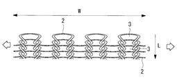
- Fig. 1 shows a diagram illustrating the configuration of the knitted layer.
- the knitted layer 1 is a layer knitted by combining continuous loops 3 of the first reinforcing fiber yarns 2.
- the loop 3 may be bound in either the vertical direction (length direction L) or the horizontal direction (width direction W).
- FIG. 1 illustrates the knitted material layer 1 when the loop 3 is bound in the vertical direction (weft knitting).
- the knitted layer 1 has a stretching performance of stretching in at least two directions of the length direction L and the width direction W. Thereby, flexibility is generated in the length direction L and the width direction W.
- FIG. 2 illustrates a state when the knitted layer 1 of FIG. 1 is pulled in the width direction W.
- the shape of the loop 3 is deformed and extends in the width direction W.
- the loop 3 can be deformed not only in the width direction W but also in other directions.
- Knitting layer 1 has a single layer structure.
- the knitted layer 1 is knitted to have a curved surface that follows the target shape.
- the target shape is the contour of the composite material part.
- the curved surface that follows the target shape may be any shape that is close to the contour of the composite material part when it is designed, and does not necessarily need to completely match the contour of the composite material part. “Near” means a difference that is within the range of the stretch performance of the knitted layer 1.
- the first reinforcing fiber yarn 2 is made of a material that is flexible enough to knit the knitted layer 1 and can be bonded to the matrix material.
- the material of the first reinforcing fiber yarn 2 is resin fiber, carbon fiber, glass fiber or the like.
- Resin fibers include polyamide fibers.
- the polyamide-based fiber is an aliphatic polyamide or aromatic polyamide fiber.
- the aliphatic polyamide is, for example, nylon (registered trademark).
- the aromatic polyamide is, for example, aramid.
- the first reinforcing fiber yarn 2 has a thickness (diameter) that can withstand the knitting of the knitted layer 1.
- the reinforcing part is formed by knitting the second reinforcing fiber yarn into the knitted layer 1 through the loop 3.
- a plurality of second reinforcing fiber yarns are knitted in the knitted layer 1.
- the plurality of second reinforcing fiber yarns knitted are oriented in one direction or two directions in the knitted layer 1.
- the plurality of second reinforcing fiber yarns knitted may be oriented in a plurality of directions in the knitted layer 1.
- FIG. 3 and FIG. 4 illustrate the orientation of the second reinforcing fiber yarn.
- FIG. 3 is a diagram in which the second reinforcing fiber yarns 4 are oriented in the width direction W of the knitted knitted fabric layer 1.
- FIG. 3 is a diagram in which the second reinforcing fiber yarns 4 are oriented in the width direction W of the knitted knitted fabric layer 1.
- the second reinforcing fiber yarns 4 are oriented in the length direction L of the knitted knitted fabric layer 1. As shown in FIGS. 3 and 4, the knitting cycle of the second reinforcing fiber yarn 4 may be the same or different in the knitted layer. In addition to the length direction L and the width direction W, the second reinforcing fiber yarn 4 may be oriented in an oblique direction.
- the material of the second reinforcing fiber yarn 4 is carbon fiber, glass fiber, resin fiber, or the like.
- the second reinforcing fiber yarn 4 has a thickness (diameter) enough to be knitted into the loop 3 of the knitted layer 1.
- the fiber bundle preferably has a thickness of 12000 or more and 30000 or less, but this is not restrictive.
- a continuous loop 3 is formed with the first reinforcing fiber yarns 2 and the knitted layer 1 is knitted.
- the knitted layer 1 can be knitted by weft knitting or warp knitting.
- the weft knitting is a flat knitting, rubber knitting, pearl knitting, lace knitting or the like.
- the warp knitting includes single / Denby and single / Bandike.
- the knitting method may be appropriately changed according to the shape of the curved surface.
- a three-dimensional structure that is partially stereoscopic can be provided by increasing or decreasing the stitches.
- the target shape is the contour of the composite part to be manufactured.
- the curved surface does not need to completely match the target shape, but is preferably a shape close to the target shape.
- the second reinforcing fiber yarns 4 are knitted into the knitted layer 1 in parallel to form the reinforced substrate 5 or the knitted reinforced substrate 6.
- the knitted layer 1 can be knitted by inlay knitting.
- Inlay knitting is a knitting method in which a yarn is inlayed (inserted) into a base knitted fabric, and is realized by passing the yarn through a loop of the knitted fabric.
- the second reinforcing fiber yarn 4 may be knitted in parallel with the knitted layer 1, or may be knitted after forming a part or all of the knitted layer 1.
- the second reinforcing fiber yarns 4 are arranged in one direction or two directions.
- the second reinforcing fiber yarns 4 are arranged in the length direction L as shown in FIG.
- the second reinforcing fiber yarns 4 are arranged in the width direction W as shown in FIG.
- the direction of some of the second reinforcing fiber yarns 4 may be aligned in the length direction L, and the direction of the remaining second reinforcing fiber yarns 4 may be aligned in the width direction W.
- a reinforced substrate 5 having a curved surface following the target shape is laminated on a mold.
- the contour of the mold is substantially the same as the contour of the composite part. Therefore, when the reinforced substrate 5 is laminated on the mold, alignment is performed so that the curved surface is aligned with the corresponding portion.
- the reinforcing substrate 5 is pressed against the mold and shaped. Since the reinforced base material 5 already has a curved surface that follows the target shape, the reinforced base material 5 can be directly pressed against the mold without being cut or the like. Since the deformation amount of the reinforced base material 5 at the time of shaping is small, even if there is a curved surface portion that does not match the contour of the mold, the stretch performance of the knitted layer 1 can cope with it. For example, when the curved surface portion is smaller than the contour of the mold, the knitted layer 1 can be stretched to make the reinforced substrate 5 conform to the contour of the mold. Thereby, even if it is a composite material part which has a complicated curved surface, a moldability can be improved.
- the reinforcing substrate 5 is laminated in a plurality of layers on the mold. The shaping is performed every time the layers are stacked or after a plurality of layers are stacked.
- FIG. 5 shows an example of lamination.
- FIG. 5A shows a molded product shape 8.
- FIG. 5B shows the reinforced base materials 7A, 7B, and 7C before shaping.
- the first reinforcing substrate 7A, the second reinforcing substrate 7B, and the third reinforcing substrate 7C have different orientations of the second reinforcing fiber yarns 4, respectively.
- the second reinforcing fiber yarn 4 is oriented at 0 °.
- the second reinforcing fiber yarns 4 are oriented at 90 °.
- the third reinforcing substrate 7C the second reinforcing fiber yarn is oriented at + 45 °.
- the first reinforcing base material 7A is laminated on a mold and then shaped
- the second reinforcing base material 7B is laminated on the shaped first reinforcing base material 7A, and then the second reinforcing base material 7B is shaped.
- the third reinforced substrate 7C is laminated on the shaped second reinforced substrate 7B, the third reinforced substrate 7C is shaped.
- the strength of the composite material component can be improved with respect to loads from a plurality of directions.
- intensively orienting the second reinforcing fiber yarn 4 in a predetermined direction it is possible to have a necessary strength in a particularly necessary direction.
- the matrix is impregnated into the reinforced base material (in FIG. 5, the first reinforced base material 7A, the second reinforced base material 7B, and the third reinforced base material 7C are deposited).
- the mold and the reinforced substrate can be covered with a bag, and the reinforced substrate can be impregnated with the matrix in a state where the inside of the bag is decompressed.
- the reinforcing base material can be fitted into a molding die composed of an upper die and a lower die, and the inside of the molding die can be decompressed to be impregnated with the matrix.
- the thicknesses of the first reinforced substrate 7A, the second reinforced substrate 7B, and the third reinforced substrate 7C impregnated with the matrix are, for example, about 0.1 mm to 0.5 mm, respectively, and the total thickness of the reinforced substrate. Is, for example, about 0.5 mm to 10 mm.
- the matrix is cured.
- the reinforced base material impregnated with the matrix is heated to a curing temperature (180 ° C. or higher) to be cured. Thereby, a composite material part can be obtained.
- the matrix is impregnated after the reinforced base material is laminated on the mold, but the present invention is not limited to this.
- the prepreg in which the reinforced base material is impregnated is formed, the prepreg is molded into the mold. It may be laminated and shaped.
Landscapes
- Chemical & Material Sciences (AREA)
- Engineering & Computer Science (AREA)
- Materials Engineering (AREA)
- Chemical Kinetics & Catalysis (AREA)
- Manufacturing & Machinery (AREA)
- Health & Medical Sciences (AREA)
- Medicinal Chemistry (AREA)
- Polymers & Plastics (AREA)
- Organic Chemistry (AREA)
- Inorganic Chemistry (AREA)
- Textile Engineering (AREA)
- Reinforced Plastic Materials (AREA)
- Knitting Of Fabric (AREA)
- Moulding By Coating Moulds (AREA)
Abstract
複雑な曲面を有する複合材部品であっても、製造コストを抑制しつつ、成形性を向上させられる強化基材、複合材部品およびそれらの製造方法を提供することを目的とする。本発明は、繊維強化複合材料製の複合材部品に用いられる強化基材(6)を製造する方法であって、前記複合材部品の輪郭を目的形状とし、第1の強化繊維糸(2)で連続的ループ(3)を作り、該連続的ループ(3)を組み合せて前記目的形状に倣った曲面を有する編物層を編成し、第2の強化繊維糸(4)を前記連続的ループ(3)に通して前記編物層に編み込んで強化部を形成する。
Description
本発明は、複合材部品用の強化基材、複合材部品およびそれらの製造方法に関するものである。
繊維強化プラスチック(FRP:Fiber Reinforced Plastics)は、繊維を強化材とし、熱可塑性樹脂または熱硬化性樹脂をマトリックスとする複合材料である。繊維強化プラスチックは、軽量かつ高強度であるため、航空機、自動車、船舶等の構造部材として広く用いられている(特許文献1)。
繊維強化プラスチックを用いて構造部材を製作する場合、まず、成形品10の形状に合わせて型紙11を作成する(図6(a)および図6(b))。次に、型紙11に合わせてシート状のプレフォーム12を裁断(図6(c))する。裁断したプレフォーム12’を成形型13に押し当て、立体形状を作り出す(図6(d))。
プレフォーム12には、一方向繊維強化材(Unidirectional fibre rein forced composite)または織物材が用いられる。一方向繊維強化材は、一方向のみに繊維方向を揃えた複合材料である。織物材は、繊維の糸を交差させてなる繊維織物を含む複合材料である。
一方向繊維強化材および織物材は、複雑な曲面に対して馴染みにくく、柔軟性および成形性が悪いという特性を有する。そのため、一方向繊維強化材および織物材のシートをそのまま複雑な曲面に押し付けて賦形しようとすると繊維配向がずれるもしくは皺が生じてしまう。そこで複雑な曲面を有する構造部材を製作する場合、部品を分割作成するか、または、成形が困難な部分については一部の繊維を切断して成形を行っている(図6(c)参照)。
繊維を切断する操作は、プレフォーム12の一体性を損ない、強度低下の原因となるため好ましくない。特許文献1では、織られた繊維プレフォームを用いて補強することで、端部結合を不要とし、かつ、等方性を確保して、複合構造物の強度を向上させている。
一方向繊維強化材または織物材を用いる場合、必要な方向に必要な分だけ繊維を配向して、構造部材の強度を確保する。そのため、分割作成や繊維裁断による強度低下があると一方向繊維強化材または織物材の積層回数が増えてしまい、製造コストの悪化につながる。
本発明は、このような事情に鑑みてなされたものであって、複雑な曲面を有する複合材部品であっても、製造コストを抑制しつつ、成形性を向上させられる複合材部品の製造方法を提供することを目的とする。
上記課題を解決するために、本発明の複合材部品用の強化基材、複合材部品およびそれらの製造方法は以下の手段を採用する。
本発明の第一の態様は、繊維強化複合材料製の複合材部品に用いられる強化基材を製造する方法であって、前記複合材部品の輪郭を目的形状とし、第1の強化繊維糸で連続的ループを作り、該連続的ループを組み合せて前記目的形状に倣った曲面を有する編物層を編成し、第2の強化繊維糸を前記連続的ループに通して前記編物層に編み込んで強化部を形成する強化基材の製造方法を提供する。
上記第一の態様では、前記強化基材を型に積層して賦形する工程を備えていてもよい。
上記第一の態様では、前記強化基材を型に積層して賦形する工程を備えていてもよい。
本発明の第二の態様は、上記第一の態様で製造された強化基材に、マトリックスを含浸させる工程を備えた複合材部品の製造方法を提供する。
本発明の第三の態様は、目的形状に倣った曲面を有し、該曲面が第1の強化繊維糸の連続的ループを組み合せて編成された編物層と、第2の強化繊維糸が前記連続的ループに通されて前記編物層に編み込まれてなる強化部と、を備えた複合材部品用の強化基材を提供する。
本発明の第四の態様は、目的形状に倣った曲面を有し、該曲面が第1の強化繊維糸の連続的ループを組み合せて編成されている編物層と、第2の強化繊維糸が前記連続的ループに通されて前記編物層に編み込まれてなる強化部と、を備えた強化基材と、マトリックスと、を含む複合材部品を提供する。
複合材部品の輪郭に倣った曲面を有するよう編物層を編み上げることで、型に押し付けて賦形する際に、強化基材の繊維配向のずれや皺を抑えることができる。そのため、賦形のために強化基材を切断する作業が不要となる、あるいはその回数を大幅に減らすことができる。編物層は連続的ループの組み合せからなるため、伸張性能を有する。これにより高い柔軟性と成形性を備えた編物層とすることができる。
編物層に第2の強化繊維を編み込むことで、高強度な強化基材とすることを実現可能とする。それにより強化基材の積層回数を低減できるため、製造コストも抑制できる。
本発明によれば、編み技術により形成した強化基材を用いることにより、複雑な曲面を有する複合材部品であっても、製造コストを抑制しつつ、成形性を向上させて複合材部品を製造できる。
以下に、本発明に係る複合材部品用の強化基材、複合材部品およびそれらの製造方法の一実施形態について、図面を参照して説明する。
複合材部品は、繊維強化複合材料製である。繊維強化複合材料は、マトリックスおよび強化基材を含んでいる。複合材部品は、複数の強化基材が積層された構成であってよい。
マトリックスは、熱硬化性樹脂、熱可塑性樹脂等である。熱硬化性樹脂は、例えば、不飽和ポリエステル、エポキシ樹脂などである。熱可塑性樹脂はポリエーテルエーテルケトン(PEEK)やポリエーテルケトンケトン(PEKK)、ポリフェニレンサルファイド(PPS)などである。
強化基材は、編物層と強化部とを備えている。強化基材は、編み技術で形成されたものである。
図1に編物層の構成を説明する図を示す。編物層1は、第1の強化繊維糸2の連続的なループ3を組み合せて編成された層である。ループ3はたて方向(長さ方向L)またはよこ方向(幅方向W)のどちらに連綴させてもよい。図1ではループ3をたて方向に連綴させた場合(緯編)の編物層1を例示している。
編物層1は、長さ方向Lおよび幅方向Wの少なくとも2方向に伸張する伸張性能を有する。それにより、長さ方向L、および、幅方向Wに柔軟性が生まれる。図2に、図1の編物層1を幅方向Wに引っ張った時の状態を例示する。緯編の編物層1を幅方向Wに引っ張ると、ループ3の形状が変形して幅方向Wに伸びる。ループ3は幅方向Wだけでなく、他の方向にも変形可能である。
編物層1は1層構成である。編物層1は目的形状に倣った曲面を有するよう編まれている。目的形状とは、複合材部品の輪郭である。目的形状に倣った曲面とは、複合材部品の設計時の輪郭に近い形状であればよく、必ずしも複合材部品の輪郭に完全に一致する必要はない。「近い」とは、編物層1の伸張性能の範囲内に収まる程度の差を意味する。
第1の強化繊維糸2は、編物層1を編める程度の柔軟性を有し、且つ、マトリックスの材料と接着可能な材料からなる。第1の強化繊維糸2の材料は、樹脂系繊維、炭素繊維、ガラス繊維などである。樹脂系繊維にはポリアミド系繊維などがある。ポリアミド系繊維は、脂肪族ポリアミドまたは芳香族ポリアミドの繊維である。脂肪族ポリアミドは、例えばナイロン(登録商標)である。芳香族ポリアミドは、例えばアラミドである。
第1の強化繊維糸2は、編物層1の編成に耐え得る程度の太さ(直径)を有する。
強化部は、第2の強化繊維糸がループ3に通されて編物層1に編み込まれてなる。第2の強化繊維糸は、編物層1に複数本、編み込まれている。編み込まれた複数の第2の強化繊維糸は、編物層1中で一方向または二方向に配向されている。編み込まれた複数の第2の強化繊維糸は、編物層1中で複数方向に配向されていてもよい。図3および図4に第2の強化繊維糸の配向を例示する。図3は、緯編した編物層1の幅方向Wに第2の強化繊維糸4を配向した図である。図4は、緯編した編物層1の長さ方向Lに第2の強化繊維糸4を配向した図である。図3,4で示すように第2の強化繊維糸4の編み込みの周期は編物層内で同一であってもよいし、異なる周期であってもよい。第2の強化繊維糸4は長さ方向L、幅方向W以外にも、斜め方向に配向してもよい。
第2の強化繊維糸4の材料は、炭素繊維、ガラス繊維、樹脂系繊維などである。第2の強化繊維糸4は、編物層1のループ3に編み込める程度の太さ(直径)を有する。第2の強化繊維糸4が炭素繊維の場合、繊維束が12000本以上30000本以下の太さを有することが好ましいが、この限りでない。
次に、強化基材および複合材部品の製造方法について説明する。
(強化基材の形成)
第1の強化繊維糸2で連続的なループ3を作り、編物層1を編成する。編物層1は、緯編または経編で編むことができる。緯編は、平編、ゴム編、パール編、レース編等である。経編は、シングル・デンビー編、シングル・バンダイク編等である。
(強化基材の形成)
第1の強化繊維糸2で連続的なループ3を作り、編物層1を編成する。編物層1は、緯編または経編で編むことができる。緯編は、平編、ゴム編、パール編、レース編等である。経編は、シングル・デンビー編、シングル・バンダイク編等である。
編物層1を編む際、目的形状に倣った曲面を編物層1に付与する。編物層1を編む際、曲面の形状に応じて適宜編み方を変えてもよい。例えば、編目を増減させることで部分的に立体的となる三次元構造を付与できる。例えば、目移しなどの手法により組織全体の幅を絞る、または、編み方を違う様式に変更することで部分的に長さや幅を変えて曲面を付与することができる。目的形状は、製造対象の複合材部品の輪郭である。曲面は、目的形状に完全に一致する必要はないが、目的形状に近い形状であることが好ましい。
編物層1を編む際、並行して第2の強化繊維糸4を編物層1に編み込み強化基材5または編み込み強化基材6とする。例えばインレイ編みで編物層1に編み込むことができる。インレイ編みとは、ベースとなる編地に糸をインレイ(挿入)する編み方で、編地のループに糸を通すことで実現する。第2の強化繊維糸4は編物層1と並行して編んでもよいし、編物層1の一部または全てを形成した後で編んでもよい。
編物層1に編み込む際、第2の強化繊維糸4の向きは一方向または二方向に揃えて配置する。例えば、図4のように第2の強化繊維糸4を長さ方向Lに揃えて配置する。例えば、図3のように第2の強化繊維糸4を幅方向Wに揃えて配置する。例えば一部の第2の強化繊維糸4の向きを長さ方向Lに揃え、残りの第2の強化繊維糸4の向きを幅方向Wに揃えて配置してもよい。
(強化基材の成形)
目的形状に倣った曲面を有する強化基材5を、型に積層する。型の輪郭は、複合材部品の輪郭と略同じである。よって、強化基材5を型に積層する際には、対応する部分に曲面が整合するよう位置合わせする。
目的形状に倣った曲面を有する強化基材5を、型に積層する。型の輪郭は、複合材部品の輪郭と略同じである。よって、強化基材5を型に積層する際には、対応する部分に曲面が整合するよう位置合わせする。
位置合わせができたら、強化基材5を型に押し付けて賦形する。強化基材5は既に目的形状に倣った曲面を有しているため、強化基材5に切り込み等を入れなくても直接型に押し付けて賦形することができる。賦形時の強化基材5の変形量が小さいため、型の輪郭に合致しない曲面部分があっても、編物層1の伸長性能で対応することができる。例えば、型の輪郭よりも曲面部分が小さい場合には、編物層1が伸びることで強化基材5を型の輪郭に馴染ませることができる。これにより複雑曲面を有する複合材部品であっても成形性を向上させることができる。
強化基材5は、型上に複数層積層する。賦形は、積層の都度行うあるいは複数層重ねてから行う。図5に、積層例を示す。図5(a)は、成形品形状8である。図5(b)は、賦形前の強化基材7A,7B,7Cである。第1強化基材7A,第2強化基材7B,第3強化基材7Cは、それぞれ第2の強化繊維糸4の配向が異なる。第1強化基材7Aは、第2の強化繊維糸4が0°に配向する。第2強化基材7Bは、第2の強化繊維糸4が90°に配向する。第3強化基材7Cは第2の強化繊維糸が+45°に配向する。例えば、第1強化基材7Aを型上に積層した後賦形し、賦形した第1強化基材7A上に第2強化基材7Bを積層した後第2強化基材7Bを賦形し、賦形した第2強化基材7B上に第3強化基材7Cを積層した後、第3強化基材7Cを賦形する。
配向の異なる第1強化基材7A,第2強化基材7B,第3強化基材7Cを重ねることで、複数方向からの荷重に対して複合材部品の強度を向上させることができる。第2の強化繊維糸4を所定方向に重点的に配向することで、特に必要な方向に必要な強度を持たせることができる。
(マトリックス含浸)
賦型後、強化基材(図5では第1強化基材7A,第2強化基材7B,第3強化基材7Cを堆積させたもの)にマトリックスを含浸させる。例えば、型および強化基材をバッグで被覆し、バッグ内部を減圧した状態で強化基材にマトリックスを含浸させることができる。例えば、上型と下型とから構成される成形型内に強化基材をはめ込み、成形型内を減圧してマトリックスを含浸させることができる。
賦型後、強化基材(図5では第1強化基材7A,第2強化基材7B,第3強化基材7Cを堆積させたもの)にマトリックスを含浸させる。例えば、型および強化基材をバッグで被覆し、バッグ内部を減圧した状態で強化基材にマトリックスを含浸させることができる。例えば、上型と下型とから構成される成形型内に強化基材をはめ込み、成形型内を減圧してマトリックスを含浸させることができる。
マトリックスを含浸させた第1強化基材7A,第2強化基材7B,第3強化基材7Cの厚さは、それぞれ例えば0.1mmから0.5mm程度であり、強化基材の総厚さは例えば0.5mmから10mm程度である。
含浸後、マトリックスを硬化させる。例えば、マトリックスとしてエポキシ樹脂を用いた場合、マトリックスを含浸させた強化基材を硬化温度(180℃以上)に加熱して、硬化させる。これにより複合材部品を得ることができる。
なお、上記実施形態では、強化基材を型に積層した後、マトリックスを含浸させているが、これに限定されず、マトリックスを強化基材に含浸させたプリプレグを形成した後、該プリプレグを型に積層して賦形してもよい。
1 編物層
2 第1の強化繊維糸
3 ループ
4 第2の強化繊維糸
5,6 強化基材
7A 第1強化基材
7B 第2強化基材
7C 第3強化基材
8 成形品形状
2 第1の強化繊維糸
3 ループ
4 第2の強化繊維糸
5,6 強化基材
7A 第1強化基材
7B 第2強化基材
7C 第3強化基材
8 成形品形状
Claims (5)
- 繊維強化複合材料製の複合材部品に用いられる強化基材を製造する方法であって、
前記複合材部品の輪郭を目的形状とし、
第1の強化繊維糸で連続的ループを作り、該連続的ループを組み合せて前記目的形状に倣った曲面を有する編物層を編成し、
第2の強化繊維糸を前記連続的ループに通して前記編物層に編み込んで強化部を形成する強化基材の製造方法。 - 前記強化基材を型に積層して賦形する工程を備えた請求項1に記載の強化基材の製造方法。
- 請求項1または請求項2に記載された方法で製造された強化基材に、マトリックスを含浸させる工程を備えた複合材部品の製造方法。
- 目的形状に倣った曲面を有し、該曲面が第1の強化繊維糸の連続的ループを組み合せて編成された編物層と、
第2の強化繊維糸が前記連続的ループに通されて前記編物層に編み込まれてなる強化部と、
を備えた複合材部品用の強化基材。 - 目的形状に倣った曲面を有し、該曲面が第1の強化繊維糸の連続的ループを組み合せて編成されている編物層と、第2の強化繊維糸が前記連続的ループに通されて前記編物層に編み込まれてなる強化部と、を備えた強化基材と、
マトリックスと、
を含む複合材部品。
Applications Claiming Priority (2)
| Application Number | Priority Date | Filing Date | Title |
|---|---|---|---|
| JP2016-113532 | 2016-06-07 | ||
| JP2016113532A JP2017218688A (ja) | 2016-06-07 | 2016-06-07 | 複合材部品用の強化基材、複合材部品およびそれらの製造方法 |
Publications (1)
| Publication Number | Publication Date |
|---|---|
| WO2017212835A1 true WO2017212835A1 (ja) | 2017-12-14 |
Family
ID=60578546
Family Applications (1)
| Application Number | Title | Priority Date | Filing Date |
|---|---|---|---|
| PCT/JP2017/017169 Ceased WO2017212835A1 (ja) | 2016-06-07 | 2017-05-01 | 複合材部品用の強化基材、複合材部品およびそれらの製造方法 |
Country Status (2)
| Country | Link |
|---|---|
| JP (1) | JP2017218688A (ja) |
| WO (1) | WO2017212835A1 (ja) |
Cited By (5)
| Publication number | Priority date | Publication date | Assignee | Title |
|---|---|---|---|---|
| US20190344477A1 (en) * | 2018-05-09 | 2019-11-14 | Fabdesigns, Inc. | System and method for knitting composite panel structures |
| CN112481797A (zh) * | 2020-12-18 | 2021-03-12 | 安踏(中国)有限公司 | 一种峰谷结构的经编鞋面织物工艺及其鞋面 |
| CN113085052A (zh) * | 2021-03-15 | 2021-07-09 | 江南大学 | 一种横编全成形头盔壳体预制件、制备方法及其头盔壳体 |
| WO2022071455A1 (ja) * | 2020-09-30 | 2022-04-07 | 日鉄ケミカル&マテリアル株式会社 | メッシュ状繊維強化複合材、メッシュ状編み構造体、メッシュ状繊維強化複合材成形用材料及びメッシュ状繊維強化複合材成形体 |
| JPWO2022071454A1 (ja) * | 2020-09-30 | 2022-04-07 |
Citations (5)
| Publication number | Priority date | Publication date | Assignee | Title |
|---|---|---|---|---|
| JPH04131682U (ja) * | 1991-05-20 | 1992-12-03 | ユニチカ株式会社 | 立体構造編地 |
| JP2008106391A (ja) * | 2006-10-25 | 2008-05-08 | Shindo Seni Kogyo Kk | シート状炭素繊維編物およびその製造方法 |
| JP2011202328A (ja) * | 2010-03-26 | 2011-10-13 | Shima Seiki Mfg Ltd | マルチレイヤ編地の編成方法とその編地及び構造体 |
| JP2014133960A (ja) * | 2013-01-10 | 2014-07-24 | Shima Seiki Mfg Ltd | 編物基材の形成方法、および編物基材 |
| JP2015017149A (ja) * | 2013-07-09 | 2015-01-29 | 三菱電機株式会社 | 繊維強化プラスチック成形体用プリフォーム、その製造方法、繊維強化プラスチック成形体の製造方法及びエレベータ用アクティブローラーガイドカバーの製造方法 |
-
2016
- 2016-06-07 JP JP2016113532A patent/JP2017218688A/ja active Pending
-
2017
- 2017-05-01 WO PCT/JP2017/017169 patent/WO2017212835A1/ja not_active Ceased
Patent Citations (5)
| Publication number | Priority date | Publication date | Assignee | Title |
|---|---|---|---|---|
| JPH04131682U (ja) * | 1991-05-20 | 1992-12-03 | ユニチカ株式会社 | 立体構造編地 |
| JP2008106391A (ja) * | 2006-10-25 | 2008-05-08 | Shindo Seni Kogyo Kk | シート状炭素繊維編物およびその製造方法 |
| JP2011202328A (ja) * | 2010-03-26 | 2011-10-13 | Shima Seiki Mfg Ltd | マルチレイヤ編地の編成方法とその編地及び構造体 |
| JP2014133960A (ja) * | 2013-01-10 | 2014-07-24 | Shima Seiki Mfg Ltd | 編物基材の形成方法、および編物基材 |
| JP2015017149A (ja) * | 2013-07-09 | 2015-01-29 | 三菱電機株式会社 | 繊維強化プラスチック成形体用プリフォーム、その製造方法、繊維強化プラスチック成形体の製造方法及びエレベータ用アクティブローラーガイドカバーの製造方法 |
Cited By (12)
| Publication number | Priority date | Publication date | Assignee | Title |
|---|---|---|---|---|
| US20190344477A1 (en) * | 2018-05-09 | 2019-11-14 | Fabdesigns, Inc. | System and method for knitting composite panel structures |
| WO2022071455A1 (ja) * | 2020-09-30 | 2022-04-07 | 日鉄ケミカル&マテリアル株式会社 | メッシュ状繊維強化複合材、メッシュ状編み構造体、メッシュ状繊維強化複合材成形用材料及びメッシュ状繊維強化複合材成形体 |
| JPWO2022071454A1 (ja) * | 2020-09-30 | 2022-04-07 | ||
| JPWO2022071455A1 (ja) * | 2020-09-30 | 2022-04-07 | ||
| WO2022071454A1 (ja) * | 2020-09-30 | 2022-04-07 | 日鉄ケミカル&マテリアル株式会社 | メッシュ状繊維強化複合材、メッシュ状編み構造体、メッシュ状繊維強化複合材成形用材料及びメッシュ状繊維強化複合材成形体 |
| CN116390840A (zh) * | 2020-09-30 | 2023-07-04 | 日铁化学材料株式会社 | 网状纤维增强复合件、网状针织构造体、网状纤维增强复合件成形用材料和网状纤维增强复合件成形体 |
| JP7686658B2 (ja) | 2020-09-30 | 2025-06-02 | 日鉄ケミカル&マテリアル株式会社 | メッシュ状繊維強化複合材、メッシュ状編み構造体、メッシュ状繊維強化複合材成形用材料及びメッシュ状繊維強化複合材成形体 |
| JP7723001B2 (ja) | 2020-09-30 | 2025-08-13 | 日鉄ケミカル&マテリアル株式会社 | メッシュ状繊維強化複合材、メッシュ状繊維強化複合材成形用材料及びメッシュ状繊維強化複合材成形体 |
| CN112481797A (zh) * | 2020-12-18 | 2021-03-12 | 安踏(中国)有限公司 | 一种峰谷结构的经编鞋面织物工艺及其鞋面 |
| CN113085052A (zh) * | 2021-03-15 | 2021-07-09 | 江南大学 | 一种横编全成形头盔壳体预制件、制备方法及其头盔壳体 |
| CN113085052B (zh) * | 2021-03-15 | 2022-07-22 | 江南大学 | 一种横编全成形头盔壳体预制件、制备方法及其头盔壳体 |
| US12442112B2 (en) | 2021-03-15 | 2025-10-14 | Jiangnan University | Full-form flat-knitted helmet shell preform, preparation method, and helmet shell thereof |
Also Published As
| Publication number | Publication date |
|---|---|
| JP2017218688A (ja) | 2017-12-14 |
Similar Documents
| Publication | Publication Date | Title |
|---|---|---|
| CN102648080B (zh) | 编织预制件、复合材料、及其制造方法 | |
| CN104718320B (zh) | 碳纤维增强复合材料用织物及其制造方法 | |
| CN107428033B (zh) | 片状增强纤维基材、预成型体及纤维增强树脂成型品 | |
| WO2017212835A1 (ja) | 複合材部品用の強化基材、複合材部品およびそれらの製造方法 | |
| KR20080076954A (ko) | 복합 구조물 응용을 위한 하이브리드 3차원 직조/적층스트럿 | |
| US20140342630A1 (en) | Woven fabric preforms and process for making the same | |
| KR20110002009A (ko) | 복합재 구조의 강화를 위한 프리폼과 이의 제조방법 | |
| US11173687B2 (en) | Reinforced substrate for composite material, composite material, and method for manufacturing reinforced substrate for composite material | |
| KR20120091168A (ko) | 직조 모재, 복합물 및 그 제조방법 | |
| JP2011074207A (ja) | 繊維強化複合材料のプリフォーム及びその製造方法 | |
| JP6835225B2 (ja) | 繊維構造体及び繊維強化複合材 | |
| JP2012096475A (ja) | 強化繊維基材、強化繊維複合材のプリフォームおよび強化繊維複合材 | |
| CN113329866A (zh) | 制备夹层形式的复合材料的方法 | |
| JP6650296B2 (ja) | 繊維強化プラスチック用基材、繊維強化プラスチック用多層基材、繊維強化プラスチック用プリフォーム及びその製造方法 | |
| JP4019822B2 (ja) | 繊維強化複合材の製造方法 | |
| JP6729712B2 (ja) | 複合材料用強化基材、複合材料および複合材料用強化基材の製造方法 | |
| Varshney et al. | Innovations in textile composite designing and their applications | |
| WO2018020945A1 (ja) | サンドイッチ構造用の多層織物及びサンドイッチ構造繊維強化複合材 | |
| JP2014058090A (ja) | 強化繊維プリフォームおよび強化繊維複合材 | |
| JP2018066086A (ja) | Rtm成形用繊維プリフォーム及び繊維強化複合材 | |
| JP2008246675A (ja) | Frp中空成形品の内圧成形法 | |
| US20210069995A1 (en) | Fiber reinforced materials with improved fatigue performance | |
| JP2020001171A (ja) | 樹脂注入成形品およびその製造方法 | |
| KR102401275B1 (ko) | 중공 단면을 가진 섬유강화복합재료 및 이의 제조방법 | |
| WO2014034606A1 (ja) | 三次元繊維構造体、それを使用したプリプレグ、及び、三次元繊維構造体の製造方法 |
Legal Events
| Date | Code | Title | Description |
|---|---|---|---|
| 121 | Ep: the epo has been informed by wipo that ep was designated in this application |
Ref document number: 17810017 Country of ref document: EP Kind code of ref document: A1 |
|
| NENP | Non-entry into the national phase |
Ref country code: DE |
|
| 122 | Ep: pct application non-entry in european phase |
Ref document number: 17810017 Country of ref document: EP Kind code of ref document: A1 |