WO2017209252A1 - Dispositif d'imagerie, procédé de commande de focalisation et programme de commande de focalisation - Google Patents
Dispositif d'imagerie, procédé de commande de focalisation et programme de commande de focalisation Download PDFInfo
- Publication number
- WO2017209252A1 WO2017209252A1 PCT/JP2017/020474 JP2017020474W WO2017209252A1 WO 2017209252 A1 WO2017209252 A1 WO 2017209252A1 JP 2017020474 W JP2017020474 W JP 2017020474W WO 2017209252 A1 WO2017209252 A1 WO 2017209252A1
- Authority
- WO
- WIPO (PCT)
- Prior art keywords
- focus control
- phase difference
- contrast
- focus
- area
- Prior art date
Links
- 238000000034 method Methods 0.000 title claims abstract description 191
- 238000003384 imaging method Methods 0.000 title claims abstract description 115
- 238000001514 detection method Methods 0.000 claims abstract description 117
- 230000003287 optical effect Effects 0.000 claims abstract description 35
- 230000005484 gravity Effects 0.000 claims description 13
- 210000001747 pupil Anatomy 0.000 claims description 13
- 230000004907 flux Effects 0.000 claims description 5
- 230000006870 function Effects 0.000 description 19
- 238000004891 communication Methods 0.000 description 17
- 230000000875 corresponding effect Effects 0.000 description 17
- 238000010586 diagram Methods 0.000 description 16
- 230000008569 process Effects 0.000 description 16
- 238000006243 chemical reaction Methods 0.000 description 14
- 230000004048 modification Effects 0.000 description 12
- 238000012986 modification Methods 0.000 description 12
- 230000001133 acceleration Effects 0.000 description 10
- 230000033001 locomotion Effects 0.000 description 6
- 230000001276 controlling effect Effects 0.000 description 4
- 230000008859 change Effects 0.000 description 3
- 238000010295 mobile communication Methods 0.000 description 3
- 230000007423 decrease Effects 0.000 description 2
- 230000004044 response Effects 0.000 description 2
- 239000004065 semiconductor Substances 0.000 description 2
- 230000005540 biological transmission Effects 0.000 description 1
- 230000000295 complement effect Effects 0.000 description 1
- 230000002596 correlated effect Effects 0.000 description 1
- 238000005401 electroluminescence Methods 0.000 description 1
- 230000005674 electromagnetic induction Effects 0.000 description 1
- 239000007788 liquid Substances 0.000 description 1
- 239000004973 liquid crystal related substance Substances 0.000 description 1
- 238000004519 manufacturing process Methods 0.000 description 1
- 239000011159 matrix material Substances 0.000 description 1
- 230000007246 mechanism Effects 0.000 description 1
- 229910044991 metal oxide Inorganic materials 0.000 description 1
- 150000004706 metal oxides Chemical class 0.000 description 1
- 230000000630 rising effect Effects 0.000 description 1
- 238000005070 sampling Methods 0.000 description 1
- 238000004611 spectroscopical analysis Methods 0.000 description 1
- 238000010897 surface acoustic wave method Methods 0.000 description 1
Images


Classifications
-
- G—PHYSICS
- G02—OPTICS
- G02B—OPTICAL ELEMENTS, SYSTEMS OR APPARATUS
- G02B7/00—Mountings, adjusting means, or light-tight connections, for optical elements
- G02B7/02—Mountings, adjusting means, or light-tight connections, for optical elements for lenses
- G02B7/04—Mountings, adjusting means, or light-tight connections, for optical elements for lenses with mechanism for focusing or varying magnification
- G02B7/09—Mountings, adjusting means, or light-tight connections, for optical elements for lenses with mechanism for focusing or varying magnification adapted for automatic focusing or varying magnification
-
- G—PHYSICS
- G02—OPTICS
- G02B—OPTICAL ELEMENTS, SYSTEMS OR APPARATUS
- G02B7/00—Mountings, adjusting means, or light-tight connections, for optical elements
- G02B7/28—Systems for automatic generation of focusing signals
- G02B7/36—Systems for automatic generation of focusing signals using image sharpness techniques, e.g. image processing techniques for generating autofocus signals
-
- G—PHYSICS
- G02—OPTICS
- G02B—OPTICAL ELEMENTS, SYSTEMS OR APPARATUS
- G02B7/00—Mountings, adjusting means, or light-tight connections, for optical elements
- G02B7/28—Systems for automatic generation of focusing signals
- G02B7/34—Systems for automatic generation of focusing signals using different areas in a pupil plane
- G02B7/346—Systems for automatic generation of focusing signals using different areas in a pupil plane using horizontal and vertical areas in the pupil plane, i.e. wide area autofocusing
-
- G—PHYSICS
- G03—PHOTOGRAPHY; CINEMATOGRAPHY; ANALOGOUS TECHNIQUES USING WAVES OTHER THAN OPTICAL WAVES; ELECTROGRAPHY; HOLOGRAPHY
- G03B—APPARATUS OR ARRANGEMENTS FOR TAKING PHOTOGRAPHS OR FOR PROJECTING OR VIEWING THEM; APPARATUS OR ARRANGEMENTS EMPLOYING ANALOGOUS TECHNIQUES USING WAVES OTHER THAN OPTICAL WAVES; ACCESSORIES THEREFOR
- G03B13/00—Viewfinders; Focusing aids for cameras; Means for focusing for cameras; Autofocus systems for cameras
- G03B13/32—Means for focusing
- G03B13/34—Power focusing
- G03B13/36—Autofocus systems
-
- H—ELECTRICITY
- H04—ELECTRIC COMMUNICATION TECHNIQUE
- H04N—PICTORIAL COMMUNICATION, e.g. TELEVISION
- H04N23/00—Cameras or camera modules comprising electronic image sensors; Control thereof
- H04N23/10—Cameras or camera modules comprising electronic image sensors; Control thereof for generating image signals from different wavelengths
-
- H—ELECTRICITY
- H04—ELECTRIC COMMUNICATION TECHNIQUE
- H04N—PICTORIAL COMMUNICATION, e.g. TELEVISION
- H04N23/00—Cameras or camera modules comprising electronic image sensors; Control thereof
- H04N23/50—Constructional details
- H04N23/55—Optical parts specially adapted for electronic image sensors; Mounting thereof
-
- H—ELECTRICITY
- H04—ELECTRIC COMMUNICATION TECHNIQUE
- H04N—PICTORIAL COMMUNICATION, e.g. TELEVISION
- H04N23/00—Cameras or camera modules comprising electronic image sensors; Control thereof
- H04N23/60—Control of cameras or camera modules
- H04N23/667—Camera operation mode switching, e.g. between still and video, sport and normal or high- and low-resolution modes
-
- H—ELECTRICITY
- H04—ELECTRIC COMMUNICATION TECHNIQUE
- H04N—PICTORIAL COMMUNICATION, e.g. TELEVISION
- H04N23/00—Cameras or camera modules comprising electronic image sensors; Control thereof
- H04N23/60—Control of cameras or camera modules
- H04N23/67—Focus control based on electronic image sensor signals
- H04N23/672—Focus control based on electronic image sensor signals based on the phase difference signals
-
- H—ELECTRICITY
- H04—ELECTRIC COMMUNICATION TECHNIQUE
- H04N—PICTORIAL COMMUNICATION, e.g. TELEVISION
- H04N23/00—Cameras or camera modules comprising electronic image sensors; Control thereof
- H04N23/60—Control of cameras or camera modules
- H04N23/67—Focus control based on electronic image sensor signals
- H04N23/673—Focus control based on electronic image sensor signals based on contrast or high frequency components of image signals, e.g. hill climbing method
-
- H—ELECTRICITY
- H04—ELECTRIC COMMUNICATION TECHNIQUE
- H04N—PICTORIAL COMMUNICATION, e.g. TELEVISION
- H04N23/00—Cameras or camera modules comprising electronic image sensors; Control thereof
- H04N23/60—Control of cameras or camera modules
- H04N23/67—Focus control based on electronic image sensor signals
- H04N23/675—Focus control based on electronic image sensor signals comprising setting of focusing regions
-
- H—ELECTRICITY
- H04—ELECTRIC COMMUNICATION TECHNIQUE
- H04N—PICTORIAL COMMUNICATION, e.g. TELEVISION
- H04N25/00—Circuitry of solid-state image sensors [SSIS]; Control thereof
- H04N25/70—SSIS architectures; Circuits associated therewith
- H04N25/703—SSIS architectures incorporating pixels for producing signals other than image signals
- H04N25/704—Pixels specially adapted for focusing, e.g. phase difference pixel sets
Definitions
- the present invention relates to an imaging apparatus, a focus control method, and a focus control program.
- an imaging device such as a digital still camera, a digital video camera, or a smartphone with an increase in resolution of an imaging element such as a CCD (Charge Coupled Device) image sensor or a CMOS (Complementary Metal Oxide Semiconductor) image sensor. Demand is rising rapidly. Note that an information device having the above imaging function is referred to as an imaging device.
- CCD Charge Coupled Device
- CMOS Complementary Metal Oxide Semiconductor
- These imaging apparatuses employ a contrast AF (Auto Focus) method or a phase difference AF method as a focusing control method for focusing on a main subject.
- a contrast AF Auto Focus
- a phase difference AF method as a focusing control method for focusing on a main subject.
- Patent Document 1 and Patent Document 2 describe an imaging apparatus that performs focusing control by a contrast AF method.
- Patent Document 3 describes an imaging apparatus that shifts to focus control using a contrast AF method when a defocus amount calculated using a phase difference AF method is less than or equal to a threshold value.
- Patent Document 4 describes an imaging apparatus that performs focus control by the phase difference AF method until the subject enters the depth of field, and then shifts to focus control by the contrast AF method.
- Patent Document 5 discloses a mode for performing focus control by the phase difference AF method, a mode for selectively performing focus control combining the phase difference AF method and the contrast AF method, and focus control by the contrast AF method, An image pickup apparatus capable of setting is described.
- Japanese Unexamined Patent Publication No. 2011-215482 Japanese Unexamined Patent Publication No. 2014-149540 Japanese Unexamined Patent Publication No. 2013-041075 Japanese Unexamined Patent Publication No. 2006-350188 Japanese Unexamined Patent Publication No. 2007-179029
- phase difference AF method and the contrast AF method have advantages and disadvantages, focusing accuracy can be improved by using the phase difference AF method and the contrast AF method separately.
- the imaging apparatus described in Patent Document 5 is high-speed when a mode for selectively performing focus control using the contrast AF method and focus control combining the contrast AF method and the phase difference AF method is set. In an imaging scene that keeps focusing on a moving subject, focusing accuracy decreases. In addition, when the mode for performing the focus control by the phase difference AF method is set, the focus accuracy decreases when the subject that is not good at the phase difference AF method is imaged.
- the present invention has been made in view of the above circumstances, and an object thereof is to provide an imaging device, a focus control method, and a focus control program capable of realizing high-speed and high-precision focus control. To do.
- An imaging device detects a signal corresponding to one of a pair of light beams that have passed through different portions of a pupil region of the imaging optical system and an imaging element that captures an object through an imaging optical system including a focus lens.
- the signal detection unit, the second signal detection unit for detecting a signal corresponding to the other of the pair of light beams, and the focus control for driving the focus lens to focus on the main subject is continuously performed a plurality of times.
- focusing control by the phase difference AF method using the correlation calculation result of the detection signal of the first signal detection unit and the detection signal of the second signal detection unit, and imaging captured by the imaging element An in-focus control unit that selectively performs in-focus control using a contrast AF method that uses the contrast of an image, and the in-focus control unit performs in-focus by the phase difference AF method. If the state in which the reliability of the focus control by the phase difference AF method is not more than a threshold value continues N times while N is an arbitrary natural number of 2 or more during continuous control, the contrast AF method Is used to perform focusing control.
- the focus control method of the present invention provides a pupil region of the imaging optical system when the focus lens of the imaging optical system including the focus lens is driven to perform focusing control to focus on a main subject a plurality of times.
- the detection signal of the first signal detection unit that detects a signal corresponding to one of the pair of light beams that have passed through different parts of the pair and the detection before the second signal detection unit that detects a signal corresponding to the other of the pair of light beams Focus control by the phase difference AF method using the result of signal correlation calculation and focus control by the contrast AF method using the contrast of the captured image captured by the image sensor that captures the subject through the imaging optical system.
- the focus control program provides a pupil region of the imaging optical system when the focus lens of the imaging optical system including the focus lens is driven to perform focusing control to focus on a main subject a plurality of times.
- the detection signal of the first signal detection unit that detects a signal corresponding to one of the pair of light beams that have passed through different parts of the pair and the detection before the second signal detection unit that detects a signal corresponding to the other of the pair of light beams Focus control by the phase difference AF method using the result of signal correlation calculation and focus control by the contrast AF method using the contrast of the captured image captured by the image sensor that captures the subject through the imaging optical system.
- a focusing control program for causing a computer to execute a focusing control step for selectively performing any one of the above-described phase differences.
- N is continued N times as an arbitrary natural number of 2 or more while the focus control by the F method is continuously performed. Performs focus control by the contrast AF method.
- an imaging apparatus a focus control method, and a focus control program that can realize high-speed and high-precision focus control.
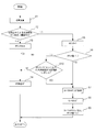
- FIG. 1 is a diagram illustrating a schematic configuration of a digital camera that is an embodiment of an imaging apparatus of the present invention.
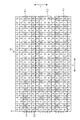
- FIG. 2 is a schematic plan view illustrating a configuration of an image sensor 5 mounted on the digital camera illustrated in FIG. 1.
- FIG. 3 is a partially enlarged view of one AF area 53 shown in FIG. 2. It is the figure which showed the pixel for a phase difference detection which comprises the arbitrary pair rows shown in FIG. It is a figure showing the section composition of pixel 52A for phase contrast detection. It is a figure which shows the structure which made all the pixels contained in the image pick-up element 5 an imaging pixel, and divided
- 3 is a flowchart for explaining an operation in a continuous AF mode of the digital camera shown in FIG. 1.
- FIG. 6 is a flowchart for explaining a modification example of the operation of the digital camera shown in FIG. 1 in the continuous AF mode. It is a schematic diagram for demonstrating another example of a setting of a contrast AF area. It is a schematic diagram for demonstrating another example of a setting of a contrast AF area. It is a figure which shows the modification of the digital camera shown in FIG. 13 is a flowchart for explaining the operation of the digital camera shown in FIG. 12 in the continuous AF mode. It is a schematic diagram for demonstrating the example of a setting of the contrast AF area of the digital camera shown in FIG.
- FIG. 200 It is a schematic diagram for demonstrating the example of a setting of the contrast AF area of the digital camera shown in FIG.
- the external appearance of the smart phone 200 which is one Embodiment of the imaging device of this invention is shown.
- FIG. 1 is a diagram showing a schematic configuration of a digital camera which is an embodiment of an imaging apparatus of the present invention.
- the digital camera shown in FIG. 1 includes a lens device 40 having an imaging lens 1, an aperture 2, a lens control unit 4, a lens driving unit 8, and an aperture driving unit 9.
- the lens device 40 may be detachable from the digital camera body, or may be fixed to the digital camera body.
- the imaging lens 1 and the diaphragm 2 constitute an imaging optical system, and the imaging optical system includes at least a focus lens.
- This focus lens is a lens for adjusting the focal position of the imaging optical system, and is composed of a single lens or a plurality of lenses. The focus position is adjusted by moving the focus lens in the optical axis direction of the imaging optical system.
- a liquid lens capable of changing the focal position by variably controlling the curved surface of the lens may be used.
- the lens control unit 4 of the lens device 40 is configured to be able to communicate with the system control unit 11 of the digital camera body by wire or wirelessly.
- the lens control unit 4 drives the focus lens included in the imaging lens 1 through the lens driving unit 8 or drives the diaphragm 2 through the diaphragm driving unit 9 according to a command from the system control unit 11. .
- the digital camera body includes an image sensor 5 such as a CCD image sensor or a CMOS image sensor that images a subject through an imaging optical system, and an analog signal that performs analog signal processing such as correlated double sampling connected to the output of the image sensor 5.
- the analog signal processing unit 6, the analog-digital conversion circuit 7, and the image sensor driving unit 10 are controlled by the system control unit 11.
- the system control unit 11 drives the image sensor 5 through the image sensor driving unit 10 and outputs a subject image captured through the imaging optical system as a captured image signal.
- An instruction signal from the user is input to the system control unit 11 through the operation unit 14.
- the system control unit 11 includes various processors and a memory such as a RAM (Random Access Memory) and a ROM (Read Only Memory).
- a RAM Random Access Memory
- ROM Read Only Memory
- programmable logic which is a processor whose circuit configuration can be changed after manufacturing, such as a CPU (Central Processing Unit) and an FPGA (Field Programmable Gate Array), which are general-purpose processors that execute programs and perform various processes Examples include a dedicated electrical circuit that is a processor having a circuit configuration that is specifically designed to execute a specific process such as a device (Programmable Logic Device: PLD) or an ASIC (Application Specific Integrated Circuit).
- PLD Programmable Logic Device
- ASIC Application Specific Integrated Circuit
- the structures of these various processors are electric circuits in which circuit elements such as semiconductor elements are combined.
- the system control unit 11 may be configured by one of various types of processors, or a combination of two or more processors of the same type or different types (for example, a combination of a plurality of FPGAs or a combination of a CPU and an FPGA). May be.
- the system control unit 11 implements each function described later by executing a program including a focusing control program stored in a built-in ROM.
- the electric control system of this digital camera performs signal processing on the captured image signal output from the main memory 16, the memory control unit 15 connected to the main memory 16, and the analog-digital conversion circuit 7.
- a digital signal processing unit 17 that generates data
- a contrast AF processing unit 18 that determines a focus position by a contrast AF method
- a phase difference AF processing unit 19 that calculates a defocus amount by a phase difference AF method
- a detachable An external memory control unit 20 to which a recording medium 21 is connected, and a display control unit 22 to which a display unit 23 mounted on the back of the camera or the like is connected.
- the memory control unit 15, digital signal processing unit 17, contrast AF processing unit 18, phase difference AF processing unit 19, external memory control unit 20, and display control unit 22 are connected to each other by a control bus 24 and a data bus 25. It is controlled by a command from the system control unit 11.
- the contrast AF processing unit 18 and the phase difference AF processing unit 19 are functional blocks formed by the processor of the system control unit 11 executing a focusing control program and cooperating with various types of hard air.
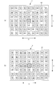
- FIG. 2 is a schematic plan view showing the configuration of the image sensor 5 mounted on the digital camera shown in FIG.
- the imaging element 5 has a light receiving surface 50 on which a large number of pixels arranged in a two-dimensional manner are arranged in a row direction X and a column direction Y orthogonal to the row direction X.
- the light receiving surface 50 has 63 focus detection areas (hereinafter referred to as AF areas) 53 that are areas to be focused (areas on which subject images to be focused are formed). Is provided.
- AF areas focus detection areas
- one or a plurality of consecutively arranged AF areas 53 shown in FIG. 2 are selected, and the object captured by the selected AF area 53 is focused. In-focus control is performed.
- the AF area 53 is an area including imaging pixels and phase difference detection pixels as pixels. Only the imaging pixels are arranged on the light receiving surface 50 excluding the AF area 53.
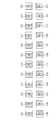
- FIG. 3 is a partially enlarged view of one AF area 53 shown in FIG.
- pixels 51 are two-dimensionally arranged.
- Each pixel 51 includes a photoelectric conversion unit such as a photodiode and a color filter formed above the photoelectric conversion unit.
- Each pixel 51 may be configured to perform spectroscopy using a photodiode structure without using a color filter.
- the letter “R” is attached to the pixel 51 (R pixel 51) including the color filter (R filter) that transmits red light.
- the letter “G” is attached to the pixel 51 (G pixel 51) including the color filter (G filter) that transmits green light.
- the letter “B” is attached to the pixel 51 (B pixel 51) including the color filter (B filter) that transmits blue light.
- the color filter array is a Bayer array over the entire light receiving surface 50.
- phase difference detection pixels 52A and 52B In the AF area 53, part of the G pixel 51 (the shaded pixels in FIG. 3) are phase difference detection pixels 52A and 52B.
- each G pixel 51 in an arbitrary pixel row among the pixel rows including the R pixel 51 and the G pixel 51 is a phase difference detection pixel 52 ⁇ / b> A.
- the G pixel 51 of the same color closest to the direction Y is the phase difference detection pixel 52B.
- phase difference detection pixel 52A and a phase difference detection pixel 52B of the same color closest to the column direction Y form a pair.
- phase difference detection pixels 52A in the third pixel row from the top in FIG. 3 and the phase difference detection pixels 52B in the fifth pixel row from the top in FIG. 3 are arranged in the row direction X.
- a pair row PL1 constituted by a plurality of pairs is formed.
- phase difference detection pixels 52A in the seventh pixel row from the top in FIG. 3 and the phase difference detection pixels 52B in the ninth pixel row from the top in FIG. A pair row PL2 composed of a plurality of pairs is formed.
- phase difference detection pixels 52A in the eleventh pixel row from the top in FIG. 3 and the phase difference detection pixels 52B in the thirteenth pixel row from the top in FIG. A pair row PL3 composed of a plurality of pairs is formed.
- a plurality of pair rows are arranged in the column direction Y.
- FIG. 4 is a diagram showing the phase difference detection pixels constituting any pair row shown in FIG.
- the phase difference detection pixel 52A is a first signal detection unit that receives a light beam that has passed through one divided region of the pupil region of the imaging lens 1 divided into two in the row direction X and detects a signal corresponding to the amount of received light. is there.
- the phase difference detection pixel 52B is a second signal detection unit that receives the light beam that has passed through the other divided region of the pupil region and detects a signal corresponding to the amount of received light.
- the plurality of pixels 51 other than the phase difference detection pixels 52A and 52B are imaging pixels.
- the imaging pixel receives a light beam that has passed through both of the two divided regions of the pupil region of the imaging lens 1 and detects a signal corresponding to the amount of received light.
- a light shielding film is provided above the photoelectric conversion unit of each pixel 51, and an opening that defines a light receiving area of the photoelectric conversion unit is formed in the light shielding film.
- the center of the aperture of the imaging pixel coincides with the center of the photoelectric conversion unit of the imaging pixel.
- the center of the opening (outlined portion in FIG. 4) of the phase difference detection pixel 52A is eccentric to the right side with respect to the center of the photoelectric conversion unit of the phase difference detection pixel 52A.
- the center of the opening (outlined portion in FIG. 4) of the phase difference detection pixel 52B is decentered to the left with respect to the center of the photoelectric conversion unit of the phase difference detection pixel 52B.
- FIG. 5 is a diagram showing a cross-sectional configuration of the phase difference detection pixel 52A. As shown in FIG. 5, in the phase difference detection pixel 52A, the opening c is eccentric to the right with respect to the photoelectric conversion unit PD.
- each of these two pixel groups includes a pixel group including the phase difference detection pixels 52A constituting an arbitrary pair row and a pixel group including the phase difference detection pixels 52B constituting the pair row.
- the phase difference in the row direction X in the image to be picked up can be detected.
- the pixel configuration of the image sensor 5 is not limited to the configuration shown in FIGS.
- all the pixels included in the imaging device 5 are imaging pixels, each imaging pixel is divided into two in the row direction X, one division is the phase difference detection pixel 52A, and the other division is The phase difference detection pixel 52B may be used.
- FIG. 6 is a diagram illustrating a configuration in which all the pixels 51 included in the image sensor 5 are imaging pixels, and each pixel 51 is divided into two.
- the pixel 51 with R in the image sensor 5 is divided into two, and the divided two are used as a phase difference detection pixel r ⁇ b> 1 and a phase difference detection pixel r ⁇ b> 2, respectively.
- the pixel 51 given G in the image pickup device 5 is divided into two, and the two divided parts are used as a phase difference detection pixel g1 and a phase difference detection pixel g2, respectively.
- the pixel 51 with B in the image sensor 5 is divided into two, and the two divided parts are used as a phase difference detection pixel b1 and a phase difference detection pixel b2, respectively.
- phase difference detection pixels r1, g1, and b1 are each a first signal detection unit
- the phase difference detection pixels r2, g2, and b2 are each a second signal detection unit.
- two phase difference detection pixels included in one pixel 51 constitute a pair.
- the system control unit 11 selectively performs either focus control by the phase difference AF method or focus control by the contrast method.
- the system control unit 11 constitutes a focusing control unit.
- the phase difference AF processing unit 19 is responsive to an instruction from the system control unit 11 to select one or a plurality of AF areas 53 (hereinafter referred to as phase difference AF areas) selected from among 63 AF areas 53 by a user operation or the like. ) Is used to calculate a phase difference, which is a relative positional deviation amount between the two images formed by the pair of light beams, using the detection signal group read from the phase difference detection pixel 52A and the phase difference detection pixel 52B. To do.
- the phase difference AF area constitutes a second subject area.
- the phase difference AF processing unit 19 determines the focus adjustment state of the imaging lens 1, here the amount away from the in-focus state and the direction away from the in-focus state, that is, the defocus amount. Ask.
- the system control unit 11 drives the focus lens based on the defocus amount, thereby performing focus control by the phase difference AF method using the result of the correlation calculation.
- the contrast AF processing unit 18 analyzes a captured image captured by the image sensor 5 and determines a focus position of the imaging lens 1 by a contrast AF method.
- the contrast AF processing unit 18 obtains the contrast (brightness / darkness difference) of the captured image obtained for each moved position (a plurality of positions) while moving the focus lens position of the imaging lens 1 under the control of the system control unit 11. Then, the focus lens position where the contrast is maximized is determined as the focus position.
- the system control unit 11 drives the focus lens based on the focus position determined by the contrast AF processing unit 18 to perform focus control by the contrast AF method using the contrast of the captured image.
- the digital camera configured as described above is equipped with a continuous AF mode in which focus control for focusing on a main subject is performed a plurality of times in succession.
- the operation of the digital camera in the continuous AF mode will be described below.
- FIG. 7 is a flowchart for explaining the operation of the digital camera shown in FIG. 1 in the continuous AF mode.
- the user of the digital camera operates the operation unit 14 in a state where any one of the 63 AF areas 53 (hereinafter referred to as one AF area 53) is selected, and gives an instruction to perform AF. Done.
- the phase difference AF processing unit 19 calculates the average value of the detection signals of the phase difference detection pixels 52A having the same position in the row direction X included in all pair rows included in the phase difference AF area.
- the correlation value is calculated by calculating the correlation value between the average values of the detection signals of the phase difference detection pixels 52B having the same position in the row direction X included in all the pair rows, and the phase difference is calculated based on the correlation value.
- the defocus amount is calculated based on the phase difference (step S1).
- the system control unit 11 determines the reliability of the defocus amount calculated in step S1, that is, the reliability of focus control by the phase difference AF method (step S2).
- the vertical axis is the correlation value calculated in step S1
- the horizontal axis is the shift amount in the row direction X of the two detection signal groups for which the correlation value is obtained
- the system control unit 11 performs focusing control by the phase difference AF method when only one minimum point exists in the above graph and the correlation value at the minimum point is lower than a predetermined value. Is determined to exceed the threshold value TH.
- Other known methods can be adopted as the reliability determination method.
- the system control unit 11 drives the focus lens based on the defocus amount calculated in step S1 (performs focus control using the phase difference AF method), and moves the focus lens to the focus position (step S4). ).
- the system control unit 11 returns the processing to step S1 after completing the focus control by the phase difference AF method, and shifts to the operation for the next AF.
- step S2 determines that the reliability of focus control by the phase difference AF method is equal to or less than the threshold value TH (step S2: NO)
- the system control unit 11 increases the count value of the built-in counter by one (step S5). Thereafter, it is determined whether or not the count value has reached N (step S6).
- N is an arbitrary natural number of 2 or more.
- the system control unit 11 performs the process of step S4 when the count value has not reached N (step S6: NO).
- step S6 If the count value has reached N (step S6: YES), the system control unit 11 performs focusing on the subject when performing focus control using the contrast AF method based on the phase difference AF area.
- a contrast AF area which is an area on which is formed, is set (step S7).
- the contrast AF area constitutes the first subject area.
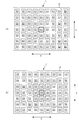
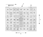
- FIG. 8 is a schematic diagram for explaining a setting example of the contrast AF area.
- phase difference AF area is an AF area 53 (enclosed by a thick frame in the figure) at the center of the 63 AF areas 53 as shown in FIG. 8A, for example.
- the system control unit 11 in step S7 as shown in FIG. 8B, the center AF area 53 and the eight AF areas 53 around the AF area 53 (in the broken line frame in the figure).
- An area surrounded by the nine AF areas 53 (the area including the nine AF areas 53 and the gap between the nine AF areas 53) is set as a contrast AF area.
- the contrast AF area may be any area that includes the phase difference AF area and is larger than the phase difference AF area, and is not limited to the setting example shown in FIG.
- the contrast AF processing unit 18 determines the focus position based on the contrast of the captured image captured by the contrast AF area. Then, the system control unit 11 moves the focus lens to this focus position and performs focus control by the contrast AF method (step S8).
- the system control unit 11 After performing the focus control by the contrast AF method, the system control unit 11 resets the setting of the contrast AF area and the count value of the built-in counter (step S9), and then returns to step S1 to perform the next process. The operation proceeds to AF operation.
- the focus control by the phase difference AF method is continuously performed. For this reason, it is possible to continue focusing even on a subject moving at high speed.
- the focus control by the phase difference AF method is continuously performed.
- the alignment by the contrast AF method is performed. Focus control is performed for the first time.
- the focus control by the contrast AF method is performed for the first time when the reliability of the focus control by the phase difference AF method is low for a certain period of time. Balance can be maintained.
- the value of N is set to about 10 to 15.
- N may be configured such that an arbitrary value can be set by the user via the operation unit 14. According to this configuration, it is possible to perform continuous AF according to the user's preference.
- the probability that the focus control by the phase difference AF method is performed is higher than the probability that the focus control by the contrast AF method is performed. For this reason, power consumption can be reduced.
- the contrast AF when performing the focus control by the contrast AF method, the contrast AF larger than the phase difference AF area used when performing the focus control by the phase difference AF method. An area is set.
- the system control unit 11 uniquely determines the focus position without performing focus control by the contrast AF method. The process of enlarging the contrast AF area and determining the in-focus position is repeated until it is done.
- the system control unit 11 may return the process to step S1 by moving the focus lens to the in-focus position when the in-focus position is uniquely determined. In this way, the focusing accuracy can be improved.
- step S7 is not essential. In this case, if the determination in step S6 is YES, the process in step S8 is performed. In step S8, the contrast AF processing unit 18 is based on the contrast of the captured image captured by the phase difference AF area. What is necessary is just to determine a focus position.
- system control unit 11 may variably control the number N described above.
- the digital camera shown in FIG. 1 assumes a first mode (e.g., a mode assuming imaging of a running train or car) assuming that the same subject is imaged with a long time in focus, and a focus. It is assumed that a second mode (for example, a mode assuming imaging of a sports landscape such as a ball game performed by a large number of people) can be set assuming that the subject to be matched is frequently switched and imaged.
- a first mode e.g., a mode assuming imaging of a running train or car
- a second mode for example, a mode assuming imaging of a sports landscape such as a ball game performed by a large number of people
- the system control unit 11 makes the value of N when set to the first mode larger than the value of N when set to the second mode.
- the value of N can be reduced to facilitate the focus control by the contrast AF method, thereby improving the captured image quality.
- the value of N is increased so that the focus control by the phase difference AF method is easily performed, so that the subject that moves at high speed is focused with high accuracy. And the quality of the captured image can be improved.
- FIG. 9 is a flowchart for explaining a modified example of the operation of the digital camera shown in FIG. 1 in the continuous AF mode. In FIG. 9, the same processing as that shown in FIG.
- the system control part 11 performs the process of step S10, when determination of step S6 is NO.
- step S10 the system control unit 11 calculates the elapsed time from the time when the count value becomes 1 (the time when the reliability of the focusing control by the phase difference AF method becomes equal to or less than the threshold value TH) to the present time. It is determined whether the elapsed time has reached a time threshold.
- step S10 NO
- the system control unit 11 determines that the elapsed time has not reached the time threshold (step S10: NO)
- the system control unit 11 performs the process of step S4.
- step S10 determines that the elapsed time has reached the time threshold value (step S10: YES)
- the system control unit 11 performs the processing after step S7.
- the reliability of the focus control by the phase difference AF method is not more than the threshold value TH, this reliability is initially less than or equal to the threshold value TH.
- focusing control by the contrast AF method is performed.
- the system controller 11 determines that the difference between the width in the row direction X of the contrast AF area and the width in the row direction X of the phase difference AF area is such that the width in the column direction Y of the contrast AF area and the column direction Y in the phase difference AF area. It is preferable to set the contrast AF area so as to be larger than the difference from the width.
- the row direction X constitutes the first direction
- the column direction Y constitutes the second direction
- the width in any direction of the phase difference AF area is the sum of the plurality of AF areas 53 and the gaps between the plurality of AF areas 53. This refers to the width of this region in any direction.
- FIG. 10 is a schematic diagram for explaining another setting example of the contrast AF area.
- phase difference AF area is an AF area 53 (enclosed by a thick frame in the figure) at the center of 63 AF areas 53 as shown in FIG. 10A, for example.
- step S7 of FIG. 7 or FIG. 9 the system control unit 11, as shown in FIG. 10B, the center AF area 53 and the two adjacent to the AF area 53 in the row direction X.
- the system control unit 11 Surrounded by five AF areas 53 including an AF area 53 and four AF areas 53 (enclosed by a broken-line frame in the drawing) including the AF area 53 adjacent to each of the two AF areas 53.
- the area is set as a contrast AF area.
- FIG. 11 is a schematic diagram for explaining still another setting example of the contrast AF area.
- phase difference AF area is an AF area 53 (enclosed by a thick frame in the figure) at the center of 63 AF areas 53 as shown in FIG. 11A, for example.
- An area surrounded by 15 AF areas 53 including those enclosed by a broken line frame in the drawing is set as a contrast AF area.
- the contrast AF area is set to a shape that is long in the row direction X in which the change in the subject distance is relatively small, so that the subject captured by the contrast AF area Therefore, it is possible to reduce the possibility of including a subject that is at a significantly different distance from the main subject. Therefore, it is possible to improve the accuracy of focusing control by the contrast AF method.
- FIG. 12 is a diagram showing a modification of the digital camera shown in FIG.
- the digital camera shown in FIG. 12 has the same configuration as that of FIG. 1 except that an acceleration sensor 26 is added.
- the acceleration sensor 26 is, for example, a sensor that detects acceleration in the three-axis directions of the x-axis, y-axis, and z-axis, and can detect the direction of gravity based on the output signal of this sensor.
- the system control unit 11 detects the direction of gravity based on the output signal of the acceleration sensor 26.
- the system control unit 11 constitutes a detection unit.
- FIG. 13 is a flowchart for explaining the operation of the digital camera shown in FIG. 12 in the continuous AF mode.
- FIG. 13 the same processes as those in FIG. 13
- the system control unit 11 detects the direction of gravity based on the output signal of the acceleration sensor 26 (step S11).
- the system control unit 11 sets a contrast AF area based on the detected gravity direction and the phase difference AF area (step S12).
- the system control unit 11 determines the width of the contrast AF area in the row direction X and the phase difference AF area as illustrated in FIG.
- the contrast AF area is set so that the difference between the width in the row direction X is greater than the difference between the width in the column direction Y of the contrast AF area and the width in the column direction Y of the phase difference AF area.
- the row direction X constitutes the first direction and the column direction Y constitutes the second direction.
- the system control unit 11 when the detected gravity direction is orthogonal to the column direction Y, the system control unit 11, as illustrated in FIG. 15, the width in the column direction Y of the contrast AF area and the column direction of the phase difference AF area.
- the contrast AF area is set such that the difference between the width of Y and the width of the contrast AF area in the row direction X is greater than the difference between the width of the phase difference AF area in the row direction X.
- the two directions being orthogonal to each other is not limited to the case where the angle formed by the two directions is completely 90 degrees, and this angle is approximately 90 degrees (for example, a range of 80 degrees to 100 degrees). Say state.
- step S12 the processing after step S8 is performed.
- the contrast AF area is set in accordance with the posture of the digital camera, so that the focus control by the contrast AF method can be performed in both the vertical shooting and the horizontal shooting.
- the focusing accuracy can be improved.
- step S10 is not essential.
- step S10 is omitted, the process of step S4 is performed when the determination of step S6 is NO.
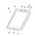
- FIG. 16 shows an appearance of a smartphone 200 that is an embodiment of the imaging apparatus of the present invention.
- a smartphone 200 illustrated in FIG. 16 includes a flat housing 201, and a display input in which a display panel 202 as a display unit and an operation panel 203 as an input unit are integrated on one surface of the housing 201. Part 204 is provided.
- Such a casing 201 includes a speaker 205, a microphone 206, an operation unit 207, and a camera unit 208.
- the configuration of the housing 201 is not limited to this, and for example, a configuration in which the display unit and the input unit are independent may be employed, or a configuration having a folding structure and a slide mechanism may be employed.
- FIG. 17 is a block diagram showing a configuration of the smartphone 200 shown in FIG.
- the main components of the smartphone include a wireless communication unit 210, a display input unit 204, a call unit 211, an operation unit 207, a camera unit 208, a storage unit 212, and an external input / output unit. 213, a GPS (Global Positioning System) receiving unit 214, a motion sensor unit 215, a power supply unit 216, and a main control unit 220.
- a wireless communication function for performing mobile wireless communication via a base station device BS (not shown) and a mobile communication network NW (not shown) is provided.
- the wireless communication unit 210 performs wireless communication with the base station apparatus BS accommodated in the mobile communication network NW according to an instruction from the main control unit 220. Using this wireless communication, transmission and reception of various file data such as audio data and image data, e-mail data, and reception of Web data and streaming data are performed.
- the display input unit 204 controls the main control unit 220 to display images (still images and moving images), character information, and the like to visually transmit information to the user and to detect user operations on the displayed information.
- a so-called touch panel which includes a display panel 202 and an operation panel 203.
- the display panel 202 uses an LCD (Liquid Crystal Display), an OELD (Organic Electro-Luminescence Display), or the like as a display device.
- LCD Liquid Crystal Display
- OELD Organic Electro-Luminescence Display
- the operation panel 203 is a device that is placed so that an image displayed on the display surface of the display panel 202 is visible and detects one or more coordinates operated by a user's finger or stylus.
- a detection signal generated due to the operation is output to the main control unit 220.
- the main control unit 220 detects an operation position (coordinates) on the display panel 202 based on the received detection signal.
- the display panel 202 and the operation panel 203 of the smartphone 200 illustrated as an embodiment of the imaging apparatus of the present invention integrally constitute a display input unit 204.
- the arrangement 203 covers the display panel 202 completely.
- the operation panel 203 may have a function of detecting a user operation even in an area outside the display panel 202.
- the operation panel 203 includes a detection area (hereinafter referred to as a display area) for an overlapping portion that overlaps the display panel 202 and a detection area (hereinafter, a non-display area) for an outer edge portion that does not overlap the other display panel 202. May be included).
- the size of the display area and the size of the display panel 202 may be completely matched, it is not always necessary to match the two.
- the operation panel 203 may include two sensitive areas of the outer edge portion and the other inner portion.
- the width of the outer edge portion is appropriately designed according to the size of the housing 201 and the like.
- examples of the position detection method employed in the operation panel 203 include a matrix switch method, a resistance film method, a surface acoustic wave method, an infrared method, an electromagnetic induction method, a capacitance method, and the like. You can also
- the call unit 211 includes a speaker 205 and a microphone 206, converts user's voice input through the microphone 206 into voice data that can be processed by the main control unit 220, and outputs the voice data to the main control unit 220. 210 or the audio data received by the external input / output unit 213 is decoded and output from the speaker 205.
- the speaker 205 can be mounted on the same surface as the surface on which the display input unit 204 is provided, and the microphone 206 can be mounted on the side surface of the housing 201.
- the operation unit 207 is a hardware key using a key switch or the like, and receives an instruction from the user.
- the operation unit 207 is mounted on the side surface of the housing 201 of the smartphone 200 and is turned on when pressed with a finger or the like, and is turned off by a restoring force such as a spring when the finger is released. It is a push button type switch.
- the storage unit 212 includes a control program and control data of the main control unit 220, application software, address data that associates the name and telephone number of a communication partner, transmitted / received e-mail data, Web data downloaded by Web browsing, The downloaded content data is stored, and streaming data and the like are temporarily stored.
- the storage unit 212 includes an internal storage unit 217 built in the smartphone and an external storage unit 218 having an external memory slot that can be freely attached and detached.
- Each of the internal storage unit 217 and the external storage unit 218 constituting the storage unit 212 includes a flash memory type (hard memory type), a hard disk type (hard disk type), a multimedia card micro type (multimedia card micro type), This is realized using a storage medium such as a card type memory (for example, MicroSD (registered trademark) memory), a RAM (Random Access Memory), a ROM (Read Only Memory), or the like.
- a flash memory type hard memory type
- hard disk type hard disk type
- multimedia card micro type multimedia card micro type
- a storage medium such as a card type memory (for example, MicroSD (registered trademark) memory), a RAM (Random Access Memory), a ROM (Read Only Memory), or the like.
- the external input / output unit 213 serves as an interface with all external devices connected to the smartphone 200, and communicates with other external devices (for example, universal serial bus (USB), IEEE 1394, etc.) or a network.
- external devices for example, universal serial bus (USB), IEEE 1394, etc.
- a network for example, Internet, wireless LAN, Bluetooth (registered trademark), RFID (Radio Frequency Identification), Infrared Data Association (IrDA) (registered trademark), UWB (Ultra Wideband) (registered trademark) ZigBee) (registered trademark, etc.) for direct or indirect connection.
- an external device connected to the smartphone 200 for example, a wired / wireless headset, a wired / wireless external charger, a wired / wireless data port, a memory card (Memory card) connected via a card socket, or a SIM (Subscriber).
- Identity Module Card / UIM (User Identity Module Card) card external audio / video equipment connected via audio / video I / O (Input / Output) terminal, external audio / video equipment connected wirelessly, yes / no
- the external input / output unit 213 transmits data received from such an external device to each component inside the smartphone 200, or allows the data inside the smartphone 200 to be transmitted to the external device. Can do.
- the GPS receiving unit 214 receives GPS signals transmitted from the GPS satellites ST1 to STn in accordance with instructions from the main control unit 220, executes a positioning calculation process based on the received plurality of GPS signals, A position consisting of longitude and altitude is detected.
- the GPS receiving unit 214 can acquire position information from the wireless communication unit 210 or the external input / output unit 213 (for example, a wireless LAN), the GPS receiving unit 214 can also detect the position using the position information.
- the motion sensor unit 215 includes, for example, a three-axis acceleration sensor, and detects the physical movement of the smartphone 200 in accordance with an instruction from the main control unit 220. By detecting the physical movement of the smartphone 200, the moving direction and acceleration of the smartphone 200 are detected. The detection result is output to the main control unit 220.
- the power supply unit 216 supplies power stored in a battery (not shown) to each unit of the smartphone 200 in accordance with an instruction from the main control unit 220.
- the main control unit 220 includes a microprocessor, operates according to a control program and control data stored in the storage unit 212, and controls each unit of the smartphone 200 in an integrated manner.
- main control unit 220 includes a mobile communication control function for controlling each unit of the communication system and an application processing function in order to perform voice communication and data communication through the wireless communication unit 210.
- the application processing function is realized by the main control unit 220 operating according to the application software stored in the storage unit 212.
- Examples of the application processing function include an infrared communication function for controlling the external input / output unit 213 to perform data communication with the opposite device, an e-mail function for transmitting / receiving e-mails, and a web browsing function for browsing web pages. .
- the main control unit 220 has an image processing function such as displaying video on the display input unit 204 based on image data (still image or moving image data) such as received data or downloaded streaming data.
- the image processing function is a function in which the main control unit 220 decodes the image data, performs image processing on the decoding result, and displays an image on the display input unit 204.
- the main control unit 220 executes display control for the display panel 202 and operation detection control for detecting a user operation through the operation unit 207 and the operation panel 203.
- the main control unit 220 By executing the display control, the main control unit 220 displays an icon for starting application software, a software key such as a scroll bar, or a window for creating an e-mail.
- scroll bar refers to a software key for accepting an instruction to move the display portion of a large image that does not fit in the display area of the display panel 202.
- the main control unit 220 detects a user operation through the operation unit 207 or accepts an operation on the icon or an input of a character string in the input field of the window through the operation panel 203. Or a display image scroll request through a scroll bar.
- the main control unit 220 causes the operation position with respect to the operation panel 203 to overlap with the display panel 202 (display area) or other outer edge part (non-display area) that does not overlap with the display panel 202.
- a touch panel control function for controlling the sensitive area of the operation panel 203 and the display position of the software key.
- the main control unit 220 can also detect a gesture operation on the operation panel 203 and execute a preset function in accordance with the detected gesture operation.
- Gesture operation is not a conventional simple touch operation, but an operation that draws a trajectory with a finger or the like, designates a plurality of positions at the same time, or combines these to draw a trajectory for at least one of a plurality of positions. means.
- the camera unit 208 includes configurations other than the external memory control unit 20, the recording medium 21, the display control unit 22, the display unit 23, and the operation unit 14 in the digital camera shown in FIG. 1 or FIG.
- the captured image data generated by the camera unit 208 can be recorded in the storage unit 212 or output through the external input / output unit 213 or the wireless communication unit 210.
- the camera unit 208 is mounted on the same surface as the display input unit 204, but the mounting position of the camera unit 208 is not limited thereto, and may be mounted on the back surface of the display input unit 204. .
- the camera unit 208 can be used for various functions of the smartphone 200.
- an image acquired by the camera unit 208 can be displayed on the display panel 202, or the image of the camera unit 208 can be used as one of operation inputs of the operation panel 203.
- the position can also be detected with reference to an image from the camera unit 208.
- the optical axis direction of the camera unit 208 of the smartphone 200 is determined without using the triaxial acceleration sensor or in combination with the triaxial acceleration sensor. It is also possible to determine the current usage environment.
- the image from the camera unit 208 can also be used in the application software.
- the position information acquired by the GPS receiver 214 to the image data of the still image or the moving image, the voice information acquired by the microphone 206 (the text information may be converted into voice information by the main control unit or the like), Posture information and the like acquired by the motion sensor unit 215 can be added and recorded in the storage unit 212, or can be output through the external input / output unit 213 and the wireless communication unit 210.
- the system control unit 11 illustrated in FIG. 1 or 12 performs the above-described processing, thereby enabling high-quality imaging.
- the case where the phase difference is detected in the row direction X is taken as an example, but the present invention can be similarly applied to the case where the phase difference is detected in the column direction Y.
- An image sensor that images a subject through an imaging optical system including a focus lens, and a first signal detection unit that detects a signal corresponding to one of a pair of light beams that have passed through different portions of the pupil region of the imaging optical system And a second signal detection unit that detects a signal corresponding to the other of the pair of light fluxes, and a mode in which focus control for driving the focus lens to focus on the main subject is performed a plurality of times in succession.
- Focus control by the phase difference AF method using the correlation calculation result of the detection signal of the first signal detection unit and the detection signal of the second signal detection unit, and the contrast of the captured image captured by the image sensor A focus control unit that selectively performs any of focus control using the contrast AF method, and the focus control unit continuously performs focus control using the phase difference AF method. If the state in which the reliability of the focus control by the phase difference AF method is not more than a threshold value continues N times with an arbitrary natural number of 2 or more, the focus control by the contrast AF method is performed.
- the focusing control unit includes a width of the second subject area in a first direction and a width of the first subject area in the first direction.
- An imaging device that makes the difference between the second subject area larger than the difference between the width in the second direction orthogonal to the first direction and the width in the second direction of the first subject area.
- the imaging apparatus further including a detection unit that detects a gravitational direction, wherein the focusing control unit uses the direction orthogonal to the gravitational direction as the first direction.
- An imaging device that sets a subject area.
- focus control for focusing the main subject by driving the focus lens of the imaging optical system including the focus lens is performed a plurality of times in succession, it passes through different parts of the pupil region of the imaging optical system.
- the result of correlation calculation of the detection signal of the first signal detection unit that detects a signal corresponding to one of the pair of light beams and the detection signal before the second signal detection unit that detects a signal corresponding to the other of the pair of light beams Focus control by phase difference AF method using the image pickup method and focus control by contrast AF method using the contrast of the captured image captured by the image sensor that captures the subject through the imaging optical system are selectively performed.
- Focusing control method for performing focus control by the contrast AF method if the state control of reliability is equal to or less than the threshold value has continued N times N as two or more arbitrary natural number.
- a focus control program for causing a computer to execute a focus control step to be performed, wherein the focus control step includes focus control by the phase difference AF method. If the state in which the focus control reliability by the phase difference AF method is not more than a threshold value continues N times while N is performed as an arbitrary natural number of 2 or more during continuous operation, the focusing by the contrast AF method is performed. Focus control program that performs focus control.
- An image sensor that images a subject through an imaging optical system including a focus lens, and a first signal detection unit that detects a signal corresponding to one of a pair of light beams that have passed through different parts of the pupil region of the imaging optical system And a second signal detection unit that detects a signal corresponding to the other of the pair of light fluxes, and a mode in which focus control for driving the focus lens to focus on the main subject is performed a plurality of times in succession.
- a processor that selectively performs focusing control using the contrast AF method, and the processor continuously performs focusing control using the phase difference AF method. If the state in which the reliability of the focus control by the phase difference AF method is not more than a threshold value continues N times while N is an arbitrary natural number of 2 or more, the focus control by the contrast AF method is performed.
- the present invention is particularly convenient and effective when applied to a digital camera or the like.
Landscapes
- Engineering & Computer Science (AREA)
- Physics & Mathematics (AREA)
- Multimedia (AREA)
- Signal Processing (AREA)
- General Physics & Mathematics (AREA)
- Optics & Photonics (AREA)
- Computer Vision & Pattern Recognition (AREA)
- Studio Devices (AREA)
- Automatic Focus Adjustment (AREA)
- Focusing (AREA)
Abstract
L'invention concerne un dispositif d'imagerie, un procédé de commande de focalisation et un programme de commande de focalisation avec lesquels il est possible de réaliser une commande de focalisation à grande vitesse et de haute précision. Une caméra numérique renferme : un élément d'imagerie (5) comprenant des pixels comportant des pixels de détection de déphasage (52A, 52B), l'élément d'imagerie (5) imageant un sujet par l'intermédiaire d'un système optique d'imagerie comportant une lentille de focalisation ; et un contrôleur de système (11) permettant d'effectuer sélectivement une commande de focalisation par un procédé d'AF de déphasage ou une commande de focalisation par un procédé d'AF de contraste, dans un mode dans lequel la commande de focalisation, dans lequel la lentille de focalisation est amenée à focaliser sur un sujet principal, est exécutée plusieurs fois de manière consécutive. Si un état dans lequel la fiabilité de la commande de focalisation par le procédé d'AF de déphasage est inférieur ou égal à une valeur seuil se produit N fois successivement (où N est un nombre entier naturel supérieur ou égal à 2) tout en effectuant une commande de focalisation par le procédé d'AF de déphasage d'une manière consécutive, le contrôleur de système (11) effectue une commande de focalisation par le procédé d'AF de contraste.
Priority Applications (8)
| Application Number | Priority Date | Filing Date | Title |
|---|---|---|---|
| JP2018520999A JP6476349B2 (ja) | 2016-06-01 | 2017-06-01 | 撮像装置、合焦制御方法、及び、合焦制御プログラム |
| CN201780033311.XA CN109196403B (zh) | 2016-06-01 | 2017-06-01 | 摄像装置、对焦控制方法及对焦控制程序 |
| US16/203,641 US10578830B2 (en) | 2016-06-01 | 2018-11-29 | Imaging device, focusing control method, and computer readable non-transitory recording medium |
| US16/795,588 US10746958B2 (en) | 2016-06-01 | 2020-02-20 | Imaging device, focusing control method, and focusing control program |
| US16/931,466 US10859791B2 (en) | 2016-06-01 | 2020-07-17 | Imaging device |
| US17/035,724 US11372196B2 (en) | 2016-06-01 | 2020-09-29 | Imaging device and focusing control method |
| US17/751,616 US11693207B2 (en) | 2016-06-01 | 2022-05-23 | Imaging device, focusing control method, and computer readable non-transitory recording medium storing a focusing control program |
| US18/313,376 US20230273398A1 (en) | 2016-06-01 | 2023-05-08 | Imaging device, focusing control method, and computer readable non-transitory recording medium storing a focusing control program |
Applications Claiming Priority (2)
| Application Number | Priority Date | Filing Date | Title |
|---|---|---|---|
| JP2016110391 | 2016-06-01 | ||
| JP2016-110391 | 2016-06-01 |
Related Child Applications (1)
| Application Number | Title | Priority Date | Filing Date |
|---|---|---|---|
| US16/203,641 Continuation US10578830B2 (en) | 2016-06-01 | 2018-11-29 | Imaging device, focusing control method, and computer readable non-transitory recording medium |
Publications (1)
| Publication Number | Publication Date |
|---|---|
| WO2017209252A1 true WO2017209252A1 (fr) | 2017-12-07 |
Family
ID=60478850
Family Applications (1)
| Application Number | Title | Priority Date | Filing Date |
|---|---|---|---|
| PCT/JP2017/020474 WO2017209252A1 (fr) | 2016-06-01 | 2017-06-01 | Dispositif d'imagerie, procédé de commande de focalisation et programme de commande de focalisation |
Country Status (4)
| Country | Link |
|---|---|
| US (6) | US10578830B2 (fr) |
| JP (1) | JP6476349B2 (fr) |
| CN (1) | CN109196403B (fr) |
| WO (1) | WO2017209252A1 (fr) |
Families Citing this family (4)
| Publication number | Priority date | Publication date | Assignee | Title |
|---|---|---|---|---|
| CN107124557A (zh) * | 2017-05-31 | 2017-09-01 | 广东欧珀移动通信有限公司 | 对焦方法、装置、计算机可读存储介质和终端 |
| CN111131703A (zh) * | 2019-12-25 | 2020-05-08 | 北京东宇宏达科技有限公司 | 一种连续变焦红外相机全程自动对焦方法 |
| KR20210105056A (ko) * | 2020-02-18 | 2021-08-26 | 에스케이하이닉스 주식회사 | 이미지 센서 및 이를 포함하는 촬영 장치 |
| US11477364B1 (en) * | 2021-04-01 | 2022-10-18 | Visera Technologies Company Limited | Solid-state image sensor |
Citations (4)
| Publication number | Priority date | Publication date | Assignee | Title |
|---|---|---|---|---|
| JP2013003486A (ja) * | 2011-06-21 | 2013-01-07 | Nikon Corp | 焦点検出装置および撮像装置 |
| WO2015045704A1 (fr) * | 2013-09-27 | 2015-04-02 | 富士フイルム株式会社 | Dispositif d'imagerie et procédé de commande de focalisation |
| JP2015087558A (ja) * | 2013-10-31 | 2015-05-07 | キヤノン株式会社 | 撮像装置、撮像システム、撮像装置の制御方法、プログラム、および、記憶媒体 |
| JP2016090816A (ja) * | 2014-11-05 | 2016-05-23 | キヤノン株式会社 | 撮像装置およびその制御方法 |
Family Cites Families (28)
| Publication number | Priority date | Publication date | Assignee | Title |
|---|---|---|---|---|
| US6445409B1 (en) * | 1997-05-14 | 2002-09-03 | Hitachi Denshi Kabushiki Kaisha | Method of distinguishing a moving object and apparatus of tracking and monitoring a moving object |
| US6272291B2 (en) * | 1998-03-13 | 2001-08-07 | Canon Kabushiki Kaisha | Focus detecting device |
| JP3592147B2 (ja) * | 1998-08-20 | 2004-11-24 | キヤノン株式会社 | 固体撮像装置 |
| US6819360B1 (en) * | 1999-04-01 | 2004-11-16 | Olympus Corporation | Image pickup element and apparatus for focusing |
| JP4324402B2 (ja) * | 2003-04-08 | 2009-09-02 | Hoya株式会社 | カメラの自動焦点調節装置 |
| JP2006350188A (ja) | 2005-06-20 | 2006-12-28 | Nikon Corp | オートフォーカス装置 |
| JP5003121B2 (ja) | 2005-11-30 | 2012-08-15 | 株式会社ニコン | 焦点調節装置、焦点調節方法、およびカメラ |
| US7728903B2 (en) | 2005-11-30 | 2010-06-01 | Nikon Corporation | Focus adjustment device, focus adjustment method and camera |
| US7751700B2 (en) * | 2006-03-01 | 2010-07-06 | Nikon Corporation | Focus adjustment device, imaging device and focus adjustment method |
| US7989745B2 (en) * | 2007-10-01 | 2011-08-02 | Nikon Corporation | Solid-state imaging device with focus detection and electronic camera with focus adjustment |
| JP5448731B2 (ja) * | 2009-11-09 | 2014-03-19 | キヤノン株式会社 | 焦点検出装置 |
| JP5610818B2 (ja) | 2010-04-01 | 2014-10-22 | キヤノン株式会社 | 撮像装置及びその制御方法 |
| CN103460103B (zh) * | 2011-03-31 | 2015-06-17 | 富士胶片株式会社 | 成像装置及其驱动方法 |
| CN103430073B (zh) * | 2011-03-31 | 2014-12-31 | 富士胶片株式会社 | 摄像装置及摄像装置的控制方法 |
| JP2013008018A (ja) * | 2011-05-25 | 2013-01-10 | Canon Inc | 撮像装置およびその制御方法 |
| JP5858683B2 (ja) | 2011-08-15 | 2016-02-10 | キヤノン株式会社 | 焦点検出装置および撮像装置 |
| EP2762942B1 (fr) * | 2011-09-28 | 2016-11-23 | Fujifilm Corporation | Elément de capture d'image à semi-conducteurs, dispositif de capture d'image et procédé de commande de focalisation |
| JP5959923B2 (ja) * | 2012-04-26 | 2016-08-02 | キヤノン株式会社 | 検出装置、その制御方法、および制御プログラム、並びに撮像装置および表示装置 |
| JP6045214B2 (ja) * | 2012-06-19 | 2016-12-14 | キヤノン株式会社 | 焦点調節装置及びその制御方法 |
| JP6149369B2 (ja) * | 2012-09-27 | 2017-06-21 | 株式会社ニコン | 撮像素子 |
| JP5705270B2 (ja) * | 2013-05-27 | 2015-04-22 | キヤノン株式会社 | 撮像装置、撮像システム、撮像装置の制御方法、プログラム、および、記憶媒体 |
| JP5990665B2 (ja) * | 2014-03-25 | 2016-09-14 | 富士フイルム株式会社 | 撮像装置及び合焦制御方法 |
| JP2014149540A (ja) | 2014-03-28 | 2014-08-21 | Canon Inc | 焦点調節装置、撮像装置、及びその制御方法 |
| KR102268712B1 (ko) * | 2014-06-23 | 2021-06-28 | 삼성전자주식회사 | 자동 초점 이미지 센서 및 이를 포함하는 디지털 영상 처리 장치 |
| CN104065885B (zh) * | 2014-06-27 | 2018-02-13 | 宇龙计算机通信科技(深圳)有限公司 | 一种终端、视频摄像装置及方法 |
| JP6429546B2 (ja) * | 2014-09-11 | 2018-11-28 | キヤノン株式会社 | 撮像装置、制御方法、プログラム、および、記憶媒体 |
| EP3018516B1 (fr) | 2014-11-05 | 2019-06-19 | Canon Kabushiki Kaisha | Appareil de capture d'image et procede pour commander un tel appareil |
| US9804357B2 (en) * | 2015-09-25 | 2017-10-31 | Qualcomm Incorporated | Phase detection autofocus using masked and unmasked photodiodes |
-
2017
- 2017-06-01 WO PCT/JP2017/020474 patent/WO2017209252A1/fr active Application Filing
- 2017-06-01 JP JP2018520999A patent/JP6476349B2/ja active Active
- 2017-06-01 CN CN201780033311.XA patent/CN109196403B/zh active Active
-
2018
- 2018-11-29 US US16/203,641 patent/US10578830B2/en active Active
-
2020
- 2020-02-20 US US16/795,588 patent/US10746958B2/en active Active
- 2020-07-17 US US16/931,466 patent/US10859791B2/en active Active
- 2020-09-29 US US17/035,724 patent/US11372196B2/en active Active
-
2022
- 2022-05-23 US US17/751,616 patent/US11693207B2/en active Active
-
2023
- 2023-05-08 US US18/313,376 patent/US20230273398A1/en active Pending
Patent Citations (4)
| Publication number | Priority date | Publication date | Assignee | Title |
|---|---|---|---|---|
| JP2013003486A (ja) * | 2011-06-21 | 2013-01-07 | Nikon Corp | 焦点検出装置および撮像装置 |
| WO2015045704A1 (fr) * | 2013-09-27 | 2015-04-02 | 富士フイルム株式会社 | Dispositif d'imagerie et procédé de commande de focalisation |
| JP2015087558A (ja) * | 2013-10-31 | 2015-05-07 | キヤノン株式会社 | 撮像装置、撮像システム、撮像装置の制御方法、プログラム、および、記憶媒体 |
| JP2016090816A (ja) * | 2014-11-05 | 2016-05-23 | キヤノン株式会社 | 撮像装置およびその制御方法 |
Also Published As
| Publication number | Publication date |
|---|---|
| US10746958B2 (en) | 2020-08-18 |
| US20220283402A1 (en) | 2022-09-08 |
| US20190094487A1 (en) | 2019-03-28 |
| US20200348486A1 (en) | 2020-11-05 |
| US11693207B2 (en) | 2023-07-04 |
| JP6476349B2 (ja) | 2019-02-27 |
| US10859791B2 (en) | 2020-12-08 |
| US10578830B2 (en) | 2020-03-03 |
| CN109196403B (zh) | 2020-11-24 |
| US20200192056A1 (en) | 2020-06-18 |
| US20230273398A1 (en) | 2023-08-31 |
| US11372196B2 (en) | 2022-06-28 |
| US20210011251A1 (en) | 2021-01-14 |
| JPWO2017209252A1 (ja) | 2019-05-16 |
| CN109196403A (zh) | 2019-01-11 |
Similar Documents
| Publication | Publication Date | Title |
|---|---|---|
| JP6165680B2 (ja) | 撮像装置 | |
| JP5799178B2 (ja) | 撮像装置及び合焦制御方法 | |
| JP5982601B2 (ja) | 撮像装置及び合焦制御方法 | |
| JP6307526B2 (ja) | 撮像装置及び合焦制御方法 | |
| JP6028112B2 (ja) | 撮像装置及び合焦制御方法 | |
| US11372196B2 (en) | Imaging device and focusing control method | |
| JP5978411B2 (ja) | 撮像装置及び合焦制御方法 | |
| WO2017057071A1 (fr) | Dispositif de commande de mise au point, procédé de commande de mise au point, programme de commande de mise au point, dispositif d'objectif, et dispositif d'imagerie | |
| JP5982600B2 (ja) | 撮像装置及び合焦制御方法 | |
| JP5542248B2 (ja) | 撮像素子及び撮像装置 | |
| JP5990665B2 (ja) | 撮像装置及び合焦制御方法 | |
| WO2017110260A1 (fr) | Dispositif de commande de mise au point, dispositif d'imagerie, procédé de commande de mise au point et programme de commande de mise au point | |
| JP6171105B2 (ja) | 撮像装置及び合焦制御方法 | |
| JP6446599B2 (ja) | 合焦制御装置、レンズ装置、撮像装置、合焦制御方法、合焦制御プログラム | |
| WO2022145322A1 (fr) | Dispositif d'imagerie, procédé de commande de focalisation et programme de commande de focalisation | |
| WO2013145887A1 (fr) | Dispositif d'imagerie et procédé d'imagerie |
Legal Events
| Date | Code | Title | Description |
|---|---|---|---|
| 121 | Ep: the epo has been informed by wipo that ep was designated in this application |
Ref document number: 17806802 Country of ref document: EP Kind code of ref document: A1 |
|
| ENP | Entry into the national phase |
Ref document number: 2018520999 Country of ref document: JP Kind code of ref document: A |
|
| NENP | Non-entry into the national phase |
Ref country code: DE |
|
| 122 | Ep: pct application non-entry in european phase |
Ref document number: 17806802 Country of ref document: EP Kind code of ref document: A1 |