WO2017208453A1 - 除電装置 - Google Patents
除電装置 Download PDFInfo
- Publication number
- WO2017208453A1 WO2017208453A1 PCT/JP2016/066647 JP2016066647W WO2017208453A1 WO 2017208453 A1 WO2017208453 A1 WO 2017208453A1 JP 2016066647 W JP2016066647 W JP 2016066647W WO 2017208453 A1 WO2017208453 A1 WO 2017208453A1
- Authority
- WO
- WIPO (PCT)
- Prior art keywords
- discharge
- discharge needle
- static eliminator
- unit
- needles
- Prior art date
- Legal status (The legal status is an assumption and is not a legal conclusion. Google has not performed a legal analysis and makes no representation as to the accuracy of the status listed.)
- Ceased
Links
Images




Classifications
-
- H—ELECTRICITY
- H05—ELECTRIC TECHNIQUES NOT OTHERWISE PROVIDED FOR
- H05F—STATIC ELECTRICITY; NATURALLY-OCCURRING ELECTRICITY
- H05F3/00—Carrying-off electrostatic charges
- H05F3/04—Carrying-off electrostatic charges by means of spark gaps or other discharge devices
Definitions
- the present invention relates to a static eliminator that neutralizes and removes static electricity from a charged object by applying a high voltage to a discharge needle and discharging from the discharge needle.
- static neutralization is used to neutralize and remove the static electricity from the manufacturing equipment and products.
- a high voltage is applied to the discharge needle for discharge, and air containing ions generated by the discharge is blown onto the object to neutralize and remove static electricity from the object.
- Patent Document 1 discloses a static eliminator that allows replacement of a discharge needle and improves maintainability.
- a rectifying duct having a cylindrical portion provided with a counter electrode and a boss portion; and a discharge module detachably attached to the cylindrical portion, the discharge module being a holder fitted to the boss portion;
- a plurality of discharge electrodes attached to the holder and projecting outward in the heel direction toward the counter electrode are provided.
- Patent Document 2 discloses a static eliminator that installs a plurality of groups of discharge needles and generates positive and negative ions to improve the static eliminability.
- a first power supply circuit for applying a high-voltage alternating voltage to the first electrode needle group; and a second power supply circuit for applying a high-voltage alternating voltage to the second electrode needle group.
- the power supply circuits output alternating voltages whose polarities are reversed.
- JP 2006-196380 A Japanese Patent Laying-Open No. 2015-015234
- the present invention has been made in view of such circumstances, and can clean the discharge needle without contaminating the work area, and can reduce the labor and time for cleaning the discharge needle.
- An object is to provide a static eliminator.
- the static eliminator according to the present invention includes a plurality of sets of discharge needles, a voltage circuit that applies a voltage for discharging to the set of discharge needles, and the voltage circuit applies the voltage to the set of discharge needles.
- the timer includes a timer, and the voltage circuit includes a discharge needle switching unit that switches a set of discharge needles to which the voltage is applied when the timer measures a predetermined time.
- the static eliminator it is possible to realize a static eliminator capable of cleaning the discharge needle without contaminating the work area and reducing the time and effort for cleaning the discharge needle. it can.
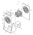
- FIG. 1 is an exploded perspective view illustrating an external configuration of a static eliminator according to Embodiment 1.
- FIG. It is an expansion perspective view which expands and shows the external appearance structure of a discharge needle unit.
- 1 is a block diagram illustrating an example of a circuit configuration of a static eliminator according to Embodiment 1.
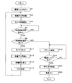
- FIG. 3 is a flowchart illustrating an operation of the static eliminator according to Embodiment 1.
- FIG. 6 is an exploded perspective view illustrating an external configuration of a static eliminator according to Embodiment 2.
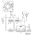
- 6 is a block diagram illustrating an example of a circuit configuration of a static eliminator according to Embodiment 2.
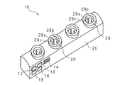
- FIG. 10 is a perspective view illustrating an external configuration of a static eliminator according to Embodiment 3.
- 10 is a block diagram illustrating an example of a circuit configuration of a static eliminator according to Embodiment 3.
- FIG. 9 is a perspective view illustrating an external configuration of a static eliminator according to a fourth embodiment
- FIG. 1 is an exploded perspective view showing an external configuration of the static eliminator 1 according to the first embodiment.
- FIG. 2 is an enlarged perspective view showing the external configuration of the discharge needle unit 7 in an enlarged manner.
- the static eliminator 1 includes a housing 2, a fan 6, a fan motor 6a, a discharge needle unit 7, a discharge needle switching motor 8, a gear mechanism 9, a power supply circuit unit 4, and a control circuit unit 5. Yes.
- the static eliminator 1 is housed in a rectangular housing 2. Circular openings 2 a and 3 a are provided in the upper part of the front surface of the housing 2 and the upper part of the cover 3 on the back surface. A radial wire mesh is fitted in each of the openings 2a and 3a.
- a leg portion 17 is attached to the lower portion of the housing 2 to support the front surface of the housing 2 so as to be rotatable in the vertical direction.
- a fan 6 is provided between the openings 2a and 3a to cause an air flow from the back side to the front side. The fan 6 is driven by a fan motor 6a.
- a discharge needle unit 7 is provided on the front side of the fan 6. Ions generated by the discharge of the discharge needle unit 7 ride on the airflow of the fan 6 and are discharged from the opening 2a.
- the rotation speed of the fan 6 can be changed by a fan adjustment volume 10 provided in the lower front portion of the housing 2, and the air flow rate of the fan 6 can be adjusted.
- the discharge needle unit 7 is a wheel-shaped insulator having eight spokes, and is supported by the outer peripheral portion in the middle of each spoke and protrudes toward the center. Eight discharge needles are provided.
- the eight discharge needles are grouped into alternately arranged discharge needles 7a and 7b, and one set of discharge needles 7a or 7b passes through four energization electrodes 24 fixed to the housing 2 side. A high voltage is applied to each.
- the discharge needles 7a and 7b are made of metal such as tungsten or stainless steel, for example.
- the discharge needle unit 7 is provided with a gear (or partial gear) (not shown) on the outer peripheral portion, and the discharge needle switching motor 8 has a gear fixed to the rotating shaft.
- a gear mechanism 9 shown in FIG. 1 includes a gear (or a partial gear) on the outer peripheral portion of the discharge needle unit 7, a gear of a rotating shaft of the discharge needle switching motor 8, and a gear meshing with both gears.
- the discharge needle switching motor (discharge needle switching unit) 8 rotates the discharge needle unit 7 by 45 degrees via a gear mechanism (discharge needle switching unit) 9 to thereby provide four discharge needles 7a and four energizing electrodes.
- the connection to 24 is switched to the connection between the four discharge needles 7 b and the four energization electrodes 24.
- the central portion of the opening 2a is connected to the discharge needle unit 7, and the discharge needle unit 7 is manually rotated 45 degrees to connect the discharge needle 7a and the energization electrode 24, and the discharge needle 7b and the energization electrode 24.
- a discharge needle switching handle 11 is provided for switching to the connection.
- the power supply circuit unit 4 includes a high voltage circuit 19 (FIG. 3) that boosts the commercial AC voltage to a high voltage, and a DC power source 22 (FIG. 3) that steps down and rectifies the commercial AC power.
- the control circuit unit 5 includes a control unit 20 (FIG. 3), receives an operation, and controls each unit of the static eliminator 1 according to the received operation.
- the static eliminator 1 is provided with a safety mechanism. For example, the cover 3 of the housing 2 is removed when the discharge needle unit 7 is cleaned or replaced, but the safety mechanism forcibly stops the discharge when the cover 3 is removed during discharge.
- the power switch 12 is a switch for turning on or off the power of the static eliminator 1.
- the timer adjustment switch 13 is a switch for setting a time (hereinafter referred to as a set operation time) (predetermined time) during which one set of discharge needles 7a or 7b operates from the start of use to switching.
- a set operation time for example, a time that is assumed to be required from the start of use of one set of discharge needles 7a or 7b until the discharge efficiency starts to be contaminated with dust is set.
- the alarm speaker (notification unit) 14 is for urging the cleaning of the discharge needles 7a and 7b when the discharge needles 7a and 7b are set for the set operating time set by the timer adjustment switch 13 (2 in this case). Is notified.
- the alarm speaker 14 also issues a warning when an abnormality occurs.
- the notification in the present embodiment is performed by sounding an alarm, but instead may be performed by, for example, turning on an LED lamp.
- the timer display unit 16 displays a set value (set operation time) set via the timer adjustment switch 13 or a count-up / count-down value (actual operation time described later). Even when the power switch 12 is turned off, the actual operation time counted up / down is stored. When the discharge needle unit 7 is cleaned or replaced, the timer reset switch 15 resets (acts to 0) the actual operation time that has been counted and displayed on the timer display unit 16 by the operation.
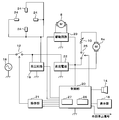
- FIG. 3 is a block diagram illustrating an example of a circuit configuration of the static eliminator 1 according to the first embodiment.
- the static eliminator 1 includes a fan motor 6a, a discharge needle switching motor 8, a fan adjustment volume 10, a power switch 12, an alarm speaker 14, a (timer) display unit 16, a high voltage circuit 19, a control unit 20, an operation unit 21, A DC power source 22, a drive circuit 23, four energization electrodes 24, and a switch 25 are provided.
- the discharge needles connected to the four energizing electrodes 24 are not shown.
- the operation unit 21 includes a power switch 12, a timer adjustment switch 13, and a timer reset switch 15 provided on the upper surface of the housing 2 (FIG. 1). Based on the operation in the operation unit 21, the power switch 12 turns on or off the connection between the commercial AC power supply 18, the high voltage circuit 19, and the DC power supply 22. When the power switch 12 is turned off, the commercial AC power supply 18 is disconnected from the high voltage circuit 19 and the DC power supply 22 after a delay time (for example, 1 second), and when it is turned on, the power switch 12 is delayed. It works without.
- the high-voltage circuit (voltage circuit) 19 is controlled by the control unit 20 to boost the voltage of the commercial AC power supply 18 to a high voltage that can be discharged by the discharge needles 7 a and 7 b and apply it to the four energizing electrodes 24.
- the DC power source 22 steps down and rectifies the power of the commercial AC power source 18 to convert it into DC power, and supplies the converted DC power to the fan motor 6a through the switch 25 and the fan adjustment volume 10.
- the switch 25 is turned on or off by the control unit 20 in accordance with an operation on the operation unit 21.
- the DC power converted by the DC power supply 22 is also supplied to the control unit 20 and the drive circuit 23.
- the drive circuit (discharge needle switching unit) 23 is controlled by the control unit (discharge needle switching unit) 20 to drive the discharge needle switching motor 8.
- the control unit 20 is composed of a microcomputer or the like, and includes a timer 26 and a nonvolatile memory 27 such as a flash memory.
- the timer 26 measures the time during which the high-voltage circuit 19 applies a voltage to the set of discharge needles 7a or 7b, that is, the time when the set of discharge needles 7a or 7b is actually operated (hereinafter referred to as actual operation time).
- the non-volatile memory 27 stores data necessary for control, such as an intermediate timing time of the timer 26 when the static eliminator 1 is powered off. When the static eliminator 1 is powered on, the timer 26 restarts the actual operation time from the intermediate time stored in the nonvolatile memory 27.
- the control unit 20 also controls the alarm speaker 14 and the display of the timer display unit 16 described above, and transmits a stop signal to the external device that is the target of static elimination when the static elimination device 1 is turned off.
- the control unit 20 When the power switch 12 is turned on (S1), the high voltage circuit 19 applies a high voltage to the four discharge needles 7a through the energizing electrodes 24, the control unit 20 turns on the switch 25, and the fan motor 6a is turned on.
- the neutralizing blower (fan 6 and discharge needle unit 7) is started by driving (S3).
- the control unit 20 causes the timer 26 to start measuring the actual operation time (S5).
- the control unit 20 continues to determine whether or not the actual operation time counted by the timer 26 has reached the set operation time (S7).
- the actual operation time counted by the timer 26 has reached the set operation time (predetermined time) (S7: YES)
- the control unit 20 resets the timer 26, that is, sets the actual operation time counted by the timer 26 to 0 (S11).
- the presence or absence of an unused discharge needle is determined by the control unit 20 based on whether or not a flag is set in the nonvolatile memory 27.
- the control unit 20 sets a flag in the nonvolatile memory 27 (S17), and when the presence or absence of an unused discharge needle is determined (S9), the flag is set. If standing, it is determined that there is no unused discharge needle, and if the flag is not standing, it is determined that there is an unused discharge needle.
- the nonvolatile memory 27 resets the flag when the discharge needle unit 7 is cleaned or replaced, the timer reset switch 15 is operated, and the actual operation time displayed on the timer display unit 16 is reset (to 0). Is done.
- the control unit 20 When there are N ( ⁇ 3) sets of discharge needles, the control unit 20 adds 1 to the variable (initial value is 0) stored in the nonvolatile memory 27 every time the discharge needles are switched. It ’s fine. That is, the value of this variable indicates the number of times the discharge needle has been switched. When determining whether or not there is an unused discharge needle, the control unit 20 determines that the value of the variable (the number of times the discharge needle is switched) in the nonvolatile memory 27 is N ⁇ 1 (1 is subtracted from the total number of discharge needle pairs). Value), it is determined that there are no unused discharge needles.
- the control unit 20 determines that an unused discharge needle still remains.
- the values of the variables in the nonvolatile memory 27 are reset when the discharge needle unit 7 is cleaned or replaced, the timer reset switch 15 is operated, and the actual operation time displayed on the timer display unit 16 is reset ( To 0).
- the control unit 20 resets the timer 26 (S11), and then stops the high-voltage circuit 19 and the fan motor 6a to stop the static elimination blower (S13).
- the control unit 20 causes the drive circuit 23 to drive the discharge needle switching motor 8 to rotate the discharge needle unit 7 by 45 degrees, to connect the energization electrode 24 and the four discharge needles 7b, and to discharge the discharge needle.
- Switching S15.
- the control unit 20 sets a flag to update the nonvolatile memory 27 (S17), activates the high-voltage circuit 19, applies a high voltage to the four discharge needles 7b, drives the fan motor 6a,
- the neutralizing blower is activated (S3).
- the control unit 20 When it is determined that there is no unused discharge needle (S9: NO), the control unit 20 issues an alarm speaker 14 to notify that the discharge needle unit 7 needs to be cleaned or replaced ( S19).
- the control unit 20 transmits a stop signal to the external device to be neutralized (S23), and then turns off the static neutralizer 1 and stops it. (S25).
- the commercial AC power supply 18 is cut off after a delay time.
- the discharge needle unit 7 is attached and cleaning such as wiping off the dust from the discharge needle is performed, or the discharge needle unit 7 is replaced with a new or cleaned discharge needle unit 7.
- the static eliminator 1 requires a predetermined set operating time (from the start of use of one set of the discharge needles 7a or 7b until it is contaminated with dust and discharge efficiency starts to decrease. Then, the discharge needle is automatically switched when the estimated time) elapses. Therefore, even if the set operation time has elapsed, if the unused discharge needle remains, the static eliminator 1 can continue to operate without cleaning, and the static eliminator 1 can be continuously operated without cleaning. The operating time can be extended.
- FIG. 5 is an exploded perspective view showing an external configuration of the static eliminator 1a according to the second embodiment.
- the static eliminator 1a has a configuration in which the discharge needle switching motor 8 and the gear mechanism 9 are omitted from the configuration of the static eliminator 1 shown in FIG. 1, and the discharge needle unit 7 is not provided with a gear.
- the needle switching handle 11 does not function. Since the other structure of the static elimination apparatus 1a is the same as that of the static elimination apparatus 1 demonstrated in FIG. 1, description is abbreviate
- FIG. 6 is a block diagram illustrating an example of a circuit configuration of the static eliminator 1a according to the second embodiment.
- the discharge needle switching motor 8 and the drive circuit 23 are omitted from the circuit configuration of the static eliminator 1 shown in FIG. 3, and instead of the four energization electrodes 24, four energization electrodes 24 a and four energizations are performed.
- the electrode 24b is provided.
- the four energization electrodes 24a are respectively connected to the four discharge needles 7a of the discharge needle unit 7 shown in FIG. 2, and the four energization electrodes 24b are respectively connected to the four discharge needles 7b of the discharge needle unit 7. is doing.
- the connection between the four discharge needles 7a and the high-voltage circuit 19 and the connection between the four discharge needles 7b and the high-voltage circuit 19 are switched by a changeover switch 28 that is controlled by the control unit 20.
- the other circuit configuration of the static eliminator 1a is the same as the circuit configuration of the static eliminator 1 described with reference to FIG.
- the operation of the static eliminator 1a configured as described above is based on the operation of the static eliminator 1 described with reference to the flow chart of FIG. 4 when the discharge needle is switched (S15), the connection between the energizing electrode 24 and the discharge needles 7a and 7b. In contrast to the switching, the static eliminator 1a is different in that the connection is switched by the switch 28 of the electric circuit.
- Other operations of the static eliminator 1a are the same as the operations of the static eliminator 1 described in the flowchart of FIG. In the static eliminator 1a of the second embodiment, the structure can be simplified, and it is possible not to stop the static elimination when the discharge needle is switched.
- FIG. 7 is a perspective view illustrating an external configuration of the static eliminator 1b according to the third embodiment.
- the static eliminator 1b is a bar-type static eliminator, and four discharge needle units 29 are arranged at equal intervals on the upper surface of an elongated rectangular housing 2b.
- the discharge needle unit 29 three discharge needles 29a, 29b, and 29c are arranged at the apexes of an equilateral triangle within a cylindrical cover.
- the three discharge needles 29a, 29b, and 29c can be replaced together.
- the neutralizing device 1b has a compressed air pipe (not shown) connected to the housing 2b, and diffuses ions for neutralization using the compressed air.
- a power switch 12 On the side surface of the housing 2b, a power switch 12, a timer adjustment switch 13, an alarm speaker 14, a timer reset switch 15, and a timer display unit 16 having functions equivalent to those of the static eliminator 1 according to the first embodiment are provided.
- FIG. 8 is a block diagram illustrating an example of a circuit configuration of the static eliminator 1b according to the third embodiment.
- the circuit related to the fan motor 6a including the discharge needle switching motor 8, the drive circuit 23, and the DC power source 22 is omitted from the circuit configuration of the static eliminator 1 shown in FIG. Instead, four energization electrodes 24c, four energization electrodes 24d, and four energization electrodes 24e are provided.
- the four energization electrodes 24c are connected to the four discharge needles 29a of the discharge needle unit 29, respectively.
- the four energization electrodes 24d are connected to the four discharge needles 29b of the discharge needle unit 29, respectively.
- the energizing electrodes 24e are connected to the four discharge needles 29c of the discharge needle unit 29, respectively.
- Each discharge needle unit 29 (FIG. 7) is configured as a connector that can be inserted and removed together with a cylindrical cover, and in the inserted state, the discharge needles 29a, 29b, and 29c and the energizing electrodes 24c on the housing 2b side. 24d and 24e are connected to each other.
- the other circuit configuration of the static eliminator 1b is the same as the circuit configuration of the static eliminator 1 described in FIG.
- the operation of the static eliminator 1b configured as described above is based on the operation of the static eliminator 1 described with reference to the flowchart of FIG. 4 when the discharge needle is switched (S15), and the connection between the energizing electrode 24 and the discharge needles 7a and 7b is established.
- the static eliminator 1b is different in that the connection is switched by the switch 28a of the electric circuit.
- the number of times of switching the connection is different (in the case of the first embodiment, it is once in the present embodiment, but twice in the present embodiment), and the fan motor 6a does not exist in the static elimination blower start (S3) and static elimination blower stop (S13). The point is different.
- the static eliminator 1b of the third embodiment by installing a plurality of discharge needles in the discharge needle unit, the static eliminator 1b is stopped by switching from the discharge needle that has reached the expiration date to the unused discharge needle by an electric circuit. The discharge needle can be switched without doing so, and the cleaning time of the discharge needle can be shortened.
- FIG. 9 is a perspective view illustrating an external configuration of the static eliminator 1c according to the fourth embodiment.
- the static eliminator 1c is a spot-type static eliminator, and a discharge needle unit 29d is installed on the top of the bowl-shaped casing 2c.
- a discharge needle unit 29d In the discharge needle unit 29d, three discharge needles 29a, 29b, and 29c are arranged at the vertices of an equilateral triangle in a cylinder forming the upper part of the housing 2c, and are covered with a funnel-shaped cover 3c that restricts the flow of air. ing.
- the three discharge needles 29a, 29b, and 29c can be replaced together.
- the neutralizing device 1c has a compressed air pipe (not shown) connected to the housing 2c, and diffuses ions for neutralization using the compressed air.
- a power switch 12 On the side surface of the housing 2c, a power switch 12, a timer adjustment switch 13, an alarm speaker 14, a timer reset switch 15, and a timer display unit 16 having functions equivalent to those of the static eliminator 1 according to the first embodiment are provided.
- the static eliminator 1c includes one each of energization electrodes 24c, 24d, and 24e in the circuit configuration of the static eliminator 1b shown in FIG.
- the energization electrode 24c is connected to the discharge needle 29a of the discharge needle unit 29d
- the energization electrode 24d is connected to the discharge needle 29b of the discharge needle unit 29d
- the energization electrode 24e is connected to the discharge needle 29c of the discharge needle unit 29d. Connected to.
- the discharge needle unit 29d (FIG. 9) is inserted from the back side of the housing 2c together with the discs fixing the discharge needles 29a, 29b, and 29c, and is fixed in the cylinder.
- each discharge needle and each energization electrode can be connected in a state where the plate is fixed in the cylinder.
- the other circuit configuration of the static eliminator 1c is the same as the circuit configuration of the static eliminator 1b described with reference to FIG.
- the operation of the static eliminator 1c having such a configuration is the same as the operation of the static eliminator 1 described with reference to the flowchart of FIG. 4, when the discharge needle is switched (S15), the connection between the energizing electrode 24 and the discharge needles 7a and 7b is established.
- the static eliminator 1c is different in that the connection is switched by the switch 28a of the electric circuit.
- the number of times of switching the connection is different (in the case of the first embodiment, it is once in the present embodiment, but twice in the present embodiment), and the fan motor 6a does not exist in the static elimination blower start (S3) and static elimination blower stop (S13). The point is different.
- the static eliminator 1c of the fourth embodiment by installing a plurality of discharge needles in the discharge needle unit, the static eliminator 1c is stopped by switching from a discharge needle that has reached the expiration date to an unused discharge needle by an electric circuit. The discharge needle can be switched without doing so, and the cleaning time of the discharge needle can be shortened.
- the static eliminator includes a plurality of sets of discharge needles 7, a voltage circuit 19 that applies a voltage for discharging to the set of discharge needles 7, and the voltage circuit 19 sets the voltage to 1 A timer 26 that counts the time applied to the pair of discharge needles 7 and a discharge needle switching unit that switches the set of discharge needles 7 to which the voltage circuit 19 applies the voltage when the timer 26 counts a predetermined time. 8, 9, 20, 23 (or 20, 28 or 20, 28a).
- the static eliminator has elapsed for a predetermined time (for example, a time required for a set of discharge needles to start being used due to contamination with dust and a decrease in discharge efficiency). If this happens, the discharge needle is automatically switched. Accordingly, if unused discharge needles remain even after a predetermined time has elapsed, the static eliminator can continue to operate without being cleaned, and the static eliminator can be continuously operated without cleaning. Can be extended. Therefore, it is possible to avoid a troublesome operation of cleaning the discharge needle every time the discharge needle is contaminated with dust (a predetermined time elapses), and it is possible to reduce labor and time for cleaning the discharge needle. Moreover, since the static eliminator does not automatically clean, the cleanliness of the clean room (working area) can be maintained.
- a predetermined time for example, a time required for a set of discharge needles to start being used due to contamination with dust and a decrease in discharge efficiency.
- the timer 26 may further include a notification unit 14 that performs notification for prompting cleaning of the discharge needle when the timer 26 measures the predetermined time for the plurality of sets.
- the plurality of sets of discharge needles 7 may be provided detachably in a lump.
Landscapes
- Elimination Of Static Electricity (AREA)
Abstract
作業エリアを汚染することなく、放電針を清掃することができると共に、放電針の清掃の手間と時間とを削減することができる除電装置を提供する。 複数組の放電針と、放電する為の電圧を1組の前記放電針に印加する電圧回路と、該電圧回路が前記電圧を1組の前記放電針に印加する時間を計時するタイマと、該タイマが所定時間を計時したときに、前記電圧回路が前記電圧を印加する放電針の組を切替える放電針切替部とを備えている。
Description
本発明は、高電圧を放電針に印加して、放電針から放電させ、帯電した物体の静電気を中和除去する除電装置に関するものである。
製造工場では、製造設備及び製造物等が帯電すると、不具合の原因となるので、除電装置を使用して、製造設備及び製造物等の静電気を中和除去している。除電装置では、放電針に高電圧を印加して放電させ、放電により発生したイオンを含む空気を対象物に吹き付けて、対象物の静電気を中和除去する。
特許文献1には、放電針の交換を可能とし、メンテナンス性を向上させる除電装置が開示されている。対向電極が設けられた筒状部及びボス部を有する整流ダクトと、筒状部に着脱自在に装着される放電モジュールとを有しており、放電モジュールはボス部に嵌合されるホルダーと、このホルダーに取り付けられ、対向電極に向けて徑方向外方に突出する複数の放電電極とを有している。放電電極の先端に異物等が付着した場合、及び放電電極が劣化した場合には、放電モジュールはボス部から取り外される。
特許文献2には、複数グループの放電針を設置し、プラスとマイナスのイオンを発生させ除電能力を向上させる除電装置が開示されている。第1の電極針グループに高圧の交番電圧を印加する第1の電源回路と、第2の電極針グループに高圧の交番電圧を印加する第2の電源回路とを備え、第1及び第2の電源回路は互いにその極性が反転した交番電圧を出力する。
上述した除電装置では、使用しているうちに、空気中に浮遊している塵挨が帯電して、放電針に引き寄せられて付着し、除電能力が低下する為、定期的に放電針の清掃を行う必要があり、手間と時間が必要であるという問題がある。
このような問題に対して、稼働中に自動的にブラシを使用して清掃する除電装置が存在するが、稼働中に清掃した場合、放電針に付着していた塵挨が、ファンの気流によって作業エリアに撒き散らされ汚染してしまう問題がある。
このような問題に対して、稼働中に自動的にブラシを使用して清掃する除電装置が存在するが、稼働中に清掃した場合、放電針に付着していた塵挨が、ファンの気流によって作業エリアに撒き散らされ汚染してしまう問題がある。
本発明は、このような事情に鑑みてなされたものであり、作業エリアを汚染することなく、放電針を清掃することができると共に、放電針の清掃の手間と時間とを削減することができる除電装置を提供することを目的とする。
本発明に係る除電装置は、複数組の放電針と、放電する為の電圧を1組の前記放電針に印加する電圧回路と、該電圧回路が前記電圧を1組の前記放電針に印加する時間を計時するタイマと、該タイマが所定時間を計時したときに、前記電圧回路が前記電圧を印加する放電針の組を切替える放電針切替部とを備えることを特徴とする。
本発明に係る除電装置によれば、作業エリアを汚染することなく、放電針を清掃することができると共に、放電針の清掃の手間と時間とを削減することができる除電装置を実現することができる。
以下に、本発明の実施例について図面に基づいて説明する。
図1は、実施例1に係る除電装置1の外観構成を示す分解斜視図である。図2は、放電針ユニット7の外観構成を拡大して示す拡大斜視図である。
図1に示すように、除電装置1は、筺体2、ファン6、ファンモータ6a、放電針ユニット7、放電針切替用モータ8、歯車機構9、電源回路部4及び制御回路部5を備えている。除電装置1は、方形の筺体2に収納されている。筺体2の正面の上部及び裏面のカバー3の上部には、円形の開口部2a及び3aが設けられている。開口部2a,3aには、それぞれ放射状の金網が嵌められている。筺体2下部には、筺体2の正面を上下方向に回動可能に支持する脚部17が取付られている。開口部2a,3aの間には、裏面側から正面側への空気の流れを起こすファン6が設けられている。ファン6は、ファンモータ6aにより駆動される。
ファン6の正面側には、放電針ユニット7が設けられる。放電針ユニット7の放電により発生したイオンは、ファン6の気流に乗って、開口部2aから吐き出される。ファン6は、筺体2の正面下部に設けられたファン調整用ボリューム10により、その回転速度を変更可能であり、ファン6の気流量を調整することができる。放電針ユニット7は、図2の拡大斜視図に示すように、8本のスポークを有する車輪形状の絶縁体であり、スポークの各中間において外周部に支持され中心方向へ向けて突設された8本の放電針を備えている。
8本の放電針は、交互に配置された放電針7a及び7bに組分けされており、1組の放電針7a又は7bは、筺体2側に固定された4つの通電用電極24を介してそれぞれ高電圧が印加される。放電針7a,7bは、例えばタングステン又はステンレス等の金属製である。
本実施例において、放電針ユニット7には、外周部に図示しない歯車(又は部分歯車)が設けられ、放電針切替用モータ8には、回転軸に歯車が固定されている。図1に示す歯車機構9は、放電針ユニット7の外周部の歯車(又は部分歯車)、放電針切替用モータ8の回転軸の歯車、及び両歯車に噛み合う歯車を含む。放電針切替用モータ(放電針切替部)8は、歯車機構(放電針切替部)9を介して放電針ユニット7を45度回転させることにより、4本の放電針7aと4つの通電用電極24との接続を、4本の放電針7bと4つの通電用電極24との接続に切替える。
開口部2aの中央部には、放電針ユニット7に連結され、手動で放電針ユニット7を45度回転させて、放電針7a及び通電用電極24の接続を、放電針7b及び通電用電極24の接続に切替える為の放電針切替ハンドル11が設けられている。電源回路部4は、商用交流電圧を高電圧に昇圧する高圧回路19(図3)と、商用交流電力を降圧して整流する直流電源22(図3)とを備えている。制御回路部5は、制御部20(図3)を備えており、操作を受付け、受付けた操作に従って除電装置1の各部を制御する。除電装置1には、安全機構が設けられている。例えば、筺体2のカバー3は、放電針ユニット7が清掃又は交換される際に取り外されるが、安全機構は、カバー3が放電中に取り外されたときに、強制的に放電を停止する。
筺体2の上面には、電源スイッチ12、タイマ調整スイッチ13、アラーム用スピーカ14、タイマリセットスイッチ15及びタイマ表示部16が設けられている。電源スイッチ12は、除電装置1の電源をオン又はオフにする為のスイッチである。タイマ調整スイッチ13は、1組の放電針7a又は7bがその使用開始から切替えまでに稼働する時間(以下、設定稼働時間という)(所定時間)を設定する為のスイッチである。設定稼働時間としては、例えば、1組の放電針7a又は7bがその使用が開始されてから塵埃に汚染されて放電効率が低下し始めるまでに要すると想定される時間が設定される。
アラーム用スピーカ(報知部)14は、タイマ調整スイッチ13で設定された設定稼働時間の放電針7a,7bの組数分(ここでは2)稼働したとき、放電針7a,7bの清掃を促す為の報知を行う。また、アラーム用スピーカ14は、異常時にも発報する。本実施例における報知は、アラームを鳴動させることにより行うが、これに代えて、例えばLEDランプを点灯させることにより行っても良い。
タイマ表示部16は、タイマ調整スイッチ13を介して設定された設定値(設定稼働時間)、又はカウントアップ/カウントダウンの数値(後述する実稼働時間)を表示する。電源スイッチ12がオフにされても、カウントアップ/カウントダウンされた実稼働時間は記憶されている。タイマリセットスイッチ15は、放電針ユニット7が清掃又は交換されたときに、操作により、それ迄に計時されタイマ表示部16に表示された実稼働時間をリセット(0に)する。
図3は、実施例1に係る除電装置1の回路構成の例を示すブロック図である。
除電装置1は、ファンモータ6a、放電針切替用モータ8、ファン調整用ボリューム10、電源スイッチ12、アラーム用スピーカ14、(タイマ)表示部16、高圧回路19、制御部20、操作部21、直流電源22、駆動回路23、4つの通電用電極24、及びスイッチ25を備えている。尚、ここでは、4つの通電用電極24にそれぞれ接続される放電針は、図示を省略している。
操作部21は、筺体2(図1)の上面に設けられた電源スイッチ12、タイマ調整スイッチ13及びタイマリセットスイッチ15を備えている。操作部21における操作に基づき、電源スイッチ12は、商用交流電源18と高圧回路19及び直流電源22との接続をオン又はオフする。電源スイッチ12は、オフに操作されたときは、遅延時間(例えば1秒間)を経て、商用交流電源18を高圧回路19及び直流電源22から遮断し、また、オンに操作されたときは、遅延なく作動する。高圧回路(電圧回路)19は、制御部20から制御されて、商用交流電源18の電圧を放電針7a,7bが放電可能な高電圧に昇圧して、4つの通電用電極24に印加する。
直流電源22は、商用交流電源18の電力を降圧、整流して直流電力に変換し、スイッチ25及びファン調整用ボリューム10を通じて変換後の直流電力をファンモータ6aに与える。スイッチ25は、操作部21における操作に応じて、制御部20がオン又はオフにする。直流電源22が変換した直流電力は、制御部20及び駆動回路23へも与えられる。駆動回路(放電針切替部)23は、制御部(放電針切替部)20から制御されて、放電針切替用モータ8を駆動する。
制御部20は、マイクロコンピュータ等で構成されており、タイマ26と、フラッシュメモリ等の不揮発性メモリ27とを備えている。タイマ26は、高圧回路19が1組の放電針7a又は7bに電圧を印加する時間、すなわち1組の放電針7a又は7bが実際に稼働した時間(以下、実稼働時間という)を計時する。不揮発性メモリ27は、除電装置1の電源オフ時におけるタイマ26の途中計時時間等、制御に必要なデータを記憶する。除電装置1の電源オン時には、タイマ26は、不揮発性メモリ27が記憶している途中計時時間から実稼働時間の計時を再開する。制御部20は、また、上述したアラーム用スピーカ14の発報、及びタイマ表示部16の表示を制御し、除電装置1の電源オフ時には、除電対象である外部機器に停止信号を発信する。
以下に、このような構成の除電装置1の動作を、図4のフローチャートを参照しながら説明する。
電源スイッチ12がオンに操作されると(S1)、高圧回路19が通電用電極24を通じて高電圧を4つの放電針7aに印加し、制御部20がスイッチ25をオンにして、ファンモータ6aを駆動させて、除電ブロア(ファン6及び放電針ユニット7)を起動させる(S3)。次いで、制御部20は、タイマ26に実稼働時間の計時を開始させる(S5)。
制御部20は、次に、タイマ26が計時した実稼働時間が設定稼働時間に到達したか否かを判定し続ける(S7)。タイマ26が計時した実稼働時間が設定稼働時間(所定時間)に到達したときは(S7:YES)、未使用の放電針が有るか否かを判定する(S9)。制御部20は、未使用の放電針が有ると判定したときは(S9:YES)、タイマ26をリセット、つまりタイマ26が計時した実稼働時間を0に設定する(S11)。
ここで、未使用の放電針の有無は、制御部20が、不揮発性メモリ27にフラグが立っているか否かで判定する。制御部20は、後述する放電針を切替えたときに(S15)、不揮発性メモリ27にフラグを立てておき(S17)、未使用の放電針の有無を判定するときに(S9)、フラグが立っていれば、未使用の放電針が無いと判定し、フラグが立っていなければ、未使用の放電針が有ると判定する。不揮発性メモリ27は、放電針ユニット7が清掃又は交換され、タイマリセットスイッチ15が操作されて、タイマ表示部16に表示された実稼働時間がリセット(0に)されたときに、フラグもリセットされる。
尚、放電針がN(≧3)組存在する場合は、制御部20は、放電針を切替える都度、不揮発性メモリ27に記憶された変数(初期値は0)に1を加算するようにしておけば良い。すなわち、この変数の値は、放電針の切り替えを行った回数を示している。制御部20は、未使用の放電針の有無を判定するときに、不揮発性メモリ27の上記変数の値(放電針の切り替え回数)がN-1(放電針の全組数から1を減算した値)となった場合に、未使用の放電針が無くなったと判定する。一方、制御部20は、不揮発性メモリ27の上記変数の値がN-1よりも小さければ、未使用の放電針が未だ残っていると判定する。不揮発性メモリ27の上記変数の値は、放電針ユニット7が清掃又は交換され、タイマリセットスイッチ15が操作されて、タイマ表示部16に表示された実稼働時間がリセットされたときに、リセット(0に)される。
制御部20は、タイマ26をリセットした後(S11)、高圧回路19及びファンモータ6aを停止させて、除電ブロアを停止させる(S13)。次いで、制御部20は、駆動回路23に放電針切替用モータ8を駆動させて、放電針ユニット7を45度回転させ、通電用電極24及び4つの放電針7bを接続させて、放電針を切替える(S15)。制御部20は、次に、フラグを立てて不揮発性メモリ27を更新し(S17)、高圧回路19を起動して高電圧を4つの放電針7bに印加し、ファンモータ6aを駆動させて、除電ブロアを起動させる(S3)。
制御部20は、未使用の放電針が無いと判定したときは(S9:NO)、アラーム用スピーカ14を発報させて、放電針ユニット7の清掃又は交換が必要であることを報知させる(S19)。制御部20は、次いで、電源スイッチ12がオフに操作されると(S21:YES)、除電対象である外部機器に停止信号を発信した後(S23)、除電装置1の電源をオフにして停止する(S25)。このとき、電源スイッチ12は、オフに操作されると、遅延時間を経て、商用交流電源18を遮断する。
除電装置1が停止した場合は(S25)、放電針ユニット7が取り付けられた状態で、放電針の塵挨を拭き取る等の清掃が行われるか、新品又は清掃済みの放電針ユニット7と交換される。
このように、本実施例1の除電装置1は、所定の設定稼働時間(1組の放電針7a又は7bがその使用が開始されてから塵埃に汚染されて放電効率が低下し始めるまでに要すると想定される時間)が経過した場合に、自動で放電針を切替える。従って、設定稼働時間が経過した場合であっても未使用の放電針が残っていれば、除電装置1は、清掃せずに稼働し続けることができ、除電装置1を清掃なしで連続して稼働できる時間を引き延ばすことができる。よって、放電針7a,7bが塵埃により汚染されるごと(設定稼働時間が経過するごと)に清掃するといった煩雑な作業を回避でき、放電針7a,7bの清掃の手間と時間とを削減することができる。また、除電装置1は自動清掃しないので、クリーンルーム(作業エリア)の清浄度を保つことができる。
図5は、実施例2に係る除電装置1aの外観構成を示す分解斜視図である。
除電装置1aは、図1で示す除電装置1の構成から、放電針切替用モータ8及び歯車機構9を省いた構成であり、放電針ユニット7には歯車は設けられておらず、また、放電針切替ハンドル11は機能しない。除電装置1aのその他の構成は、図1で説明した除電装置1の構成と同様であるので、説明を省略する。
図6は、実施例2に係る除電装置1aの回路構成の例を示すブロック図である。
除電装置1aは、図3で示す除電装置1の回路構成から、放電針切替用モータ8及び駆動回路23を省き、4つの通電用電極24に代えて、4つの通電用電極24a及び4つの通電用電極24bを備えている。4つの通電用電極24aは、図2に示す放電針ユニット7の4本の放電針7aにそれぞれ接続し、4つの通電用電極24bは、放電針ユニット7の4本の放電針7bにそれぞれ接続している。
4本の放電針7aと高圧回路19との接続、及び4本の放電針7bと高圧回路19との接続の切替えは、制御部20によってその切替えが制御される切替スイッチ28により行われる。除電装置1aのその他の回路構成は、図3で説明した除電装置1の回路構成と同様であるので、説明を省略する。
このような構成の除電装置1aの動作は、図4のフローチャートで説明した除電装置1の動作では、放電針を切替える際に(S15)、通電用電極24と放電針7a,7bとの接続を切替えるのに対して、除電装置1aでは、電気回路の切替スイッチ28により接続を切替える点が異なっている。除電装置1aのその他の動作は、図4のフローチャートで説明した除電装置1の動作と同様であるので、説明を省略する。本実施例2の除電装置1aでは、構造を単純化でき、放電針切替え時に、除電を停止しないことも可能である。
図7は、実施例3に係る除電装置1bの外観構成を示す斜視図である。
除電装置1bは、バー型除電装置であり、細長い方形の筺体2bの上面に、放電針ユニット29が4つ等間隔に並べて設置されている。放電針ユニット29は、円筒形状のカバー内で3本の放電針29a,29b,29cが正三角形の各頂点に配置されている。3本の放電針29a,29b,29cは、一括して交換することが可能である。
除電装置1bは、筺体2bに図示しない圧縮空気の配管が接続されており、圧縮空気を利用して、除電用のイオンを拡散する。筺体2bの側面には、実施例1に係る除電装置1と同等の機能を有する電源スイッチ12、タイマ調整スイッチ13、アラーム用スピーカ14、タイマリセットスイッチ15及びタイマ表示部16が設けられている。
図8は、実施例3に係る除電装置1bの回路構成の例を示すブロック図である。
除電装置1bは、図3で示す除電装置1の回路構成から、放電針切替用モータ8、駆動回路23、及び直流電源22を含むファンモータ6a関係の回路を省き、4つの通電用電極24に代えて、4つの通電用電極24c、4つの通電用電極24d、及び4つの通電用電極24eを備えている。4つの通電用電極24cは、放電針ユニット29の4本の放電針29aにそれぞれ接続し、4つの通電用電極24dは、放電針ユニット29の4本の放電針29bにそれぞれ接続し、4つの通電用電極24eは、放電針ユニット29の4本の放電針29cにそれぞれ接続している。
4本の放電針29aと高圧回路19との接続、4本の放電針29bと高圧回路19との接続,及び4本の放電針29cと高圧回路19との接続の切替えは、制御部20によってその切替えが制御される切替スイッチ28aにより行われる。各放電針ユニット29(図7)は、円筒形状のカバーごと抜き差し可能なコネクタに構成されており、差し込まれた状態で、放電針29a,29b,29cと、筺体2b側の通電用電極24c,24d,24eとがそれぞれ接続される。除電装置1bのその他の回路構成は、図3で説明した除電装置1の回路構成と同様であるので、説明を省略する。
このような構成の除電装置1bの動作は、図4のフローチャートで説明した除電装置1の動作では、放電針を切替える際に(S15)、通電用電極24と放電針7a,7bとの接続を切替えるのに対して、除電装置1bでは、電気回路の切替スイッチ28aにより接続を切替える点が異なっている。また、接続を切替える回数が異なり(実施例1の場合は1回であるが、本実施例では2回)、除電ブロア起動(S3)及び除電ブロア停止(S13)において、ファンモータ6aが存在しない点が異なっている。
除電装置1bのその他の動作は、図4のフローチャートで説明した除電装置1の動作と同様であるので、説明を省略する。本実施例3の除電装置1bでは、放電針ユニットに複数の放電針を設置することにより、使用期限に達した放電針から未使用の放電針に電気回路で切替えることで、除電装置1bを停止することなく、放電針を切替えることもでき、放電針の清掃時間を短縮することができる。
図9は、実施例4に係る除電装置1cの外観構成を示す斜視図である。
除電装置1cは、スポット型除電装置であり、蒲鉾形の筺体2cの上部に、放電針ユニット29dが設置されている。放電針ユニット29dは、筺体2c上部を形成する円筒内で3本の放電針29a,29b,29cが正三角形の各頂点に配置されており、空気の流れを絞る漏斗形状のカバー3cにより覆われている。3本の放電針29a,29b,29cは、一括して交換することが可能である。
除電装置1cは、筺体2cに図示しない圧縮空気の配管が接続されており、圧縮空気を利用して、除電用のイオンを拡散する。筺体2cの側面には、実施例1に係る除電装置1と同等の機能を有する電源スイッチ12、タイマ調整スイッチ13、アラーム用スピーカ14、タイマリセットスイッチ15及びタイマ表示部16が設けられている。
除電装置1cは、図8で示す除電装置1bの回路構成において、通電用電極24c,24d,24eをそれぞれ1つずつ備えている。通電用電極24cは、放電針ユニット29dの放電針29aに接続し、通電用電極24dは、放電針ユニット29dの放電針29bに接続し、通電用電極24eは、放電針ユニット29dの放電針29cに接続している。
放電針29aと高圧回路19との接続、放電針29bと高圧回路19との接続,及び放電針29cと高圧回路19との接続の切替えは、制御部20によってその切替えが制御される切替スイッチ28aにより行われる。放電針ユニット29d(図9)は、放電針29a,29b,29cを固定する円板ごと、筺体2cの背面側から差込まれ、円筒内に固定される。
例えば、円板の外周部に放電針29a,29b,29cの各電極を個別に露出させておき、円筒の内周部に通電用電極24c,24d,24eを個別に露出させておけば、円板が円筒内に固定された状態で、各放電針と各通電用電極とを接続することが可能である。その他、円板が円筒内に固定された状態で、コネクタにより各放電針と各通電用電極とを接続することも可能である。除電装置1cのその他の回路構成は、図8で説明した除電装置1bの回路構成と同様であるので、説明を省略する。
このような構成の除電装置1cの動作は、図4のフローチャートで説明した除電装置1の動作では、放電針を切替える際に(S15)、通電用電極24と放電針7a,7bとの接続を切替えるのに対して、除電装置1cでは、電気回路の切替スイッチ28aにより接続を切替える点が異なっている。また、接続を切替える回数が異なり(実施例1の場合は1回であるが、本実施例では2回)、除電ブロア起動(S3)及び除電ブロア停止(S13)において、ファンモータ6aが存在しない点が異なっている。
除電装置1cのその他の動作は、図4のフローチャートで説明した除電装置1の動作と同様であるので、説明を省略する。本実施例4の除電装置1cでは、放電針ユニットに複数の放電針を設置することにより、使用期限に達した放電針から未使用の放電針に電気回路で切替えることで、除電装置1cを停止することなく、放電針を切替えることもでき、放電針の清掃時間を短縮することができる。
以上、本発明の幾つかの実施例について説明した。このように、実施例に係る除電装置は、複数組の放電針7と、放電する為の電圧を1組の前記放電針7に印加する電圧回路19と、該電圧回路19が前記電圧を1組の前記放電針7に印加する時間を計時するタイマ26と、該タイマ26が所定時間を計時したときに、前記電圧回路19が前記電圧を印加する放電針7の組を切替える放電針切替部8,9,20,23(又は20,28又は20,28a)とを備える。
上記構成によれば、除電装置は、所定時間(例えば、1組の放電針がその使用が開始されてから塵埃に汚染されて放電効率が低下し始めるまでに要すると想定される時間)が経過した場合に、自動で放電針を切替える。従って、所定時間が経過した場合であっても未使用の放電針が残っていれば、除電装置は、清掃せずに稼働し続けることができ、除電装置を清掃なしで連続して稼働できる時間を引き延ばすことができる。よって、放電針が塵埃により汚染されるごと(所定時間が経過するごと)に清掃するといった煩雑な作業を回避でき、放電針の清掃の手間と時間とを削減することができる。また、除電装置は自動清掃しないので、クリーンルーム(作業エリア)の清浄度を保つことができる。
上記実施例に係る除電装置において、前記タイマ26が、前記複数組分の前記所定時間を計時したときに、放電針の清掃を促す為の報知を行う報知部14を更に備えてもよい。
上記実施例に係る除電装置において、前記複数組の放電針7は、一括して着脱可能に設けられていてもよい。
本実施例1~4は、全ての点で例示であって制限的なものではないと考えるべきである。本発明の範囲は上述の説明ではなく請求の範囲によって示され、請求の範囲と均等の意味及び範囲内での全ての変更が含まれることが意図される。
1,1a,1b,1c 除電装置
2,2b,2c 筺体
3,3c カバー
4 電源回路部
5 制御回路部
6 ファン
6a ファンモータ
7,29,29d 放電針ユニット
7a,7b,29a,29b,29c 放電針
8 放電針切替用モータ(放電針切替部)
9 歯車機構(放電針切替部)
11 放電針切替ハンドル
14 アラーム用スピーカ(報知部)
19 高圧回路(電圧回路)
20 制御部(放電針切替部)
21 操作部
23 駆動回路(放電針切替部)
24,24a,24b,24c,24d,24e 通電用電極
26 タイマ
28,28a 切替スイッチ(放電針切替部)
2,2b,2c 筺体
3,3c カバー
4 電源回路部
5 制御回路部
6 ファン
6a ファンモータ
7,29,29d 放電針ユニット
7a,7b,29a,29b,29c 放電針
8 放電針切替用モータ(放電針切替部)
9 歯車機構(放電針切替部)
11 放電針切替ハンドル
14 アラーム用スピーカ(報知部)
19 高圧回路(電圧回路)
20 制御部(放電針切替部)
21 操作部
23 駆動回路(放電針切替部)
24,24a,24b,24c,24d,24e 通電用電極
26 タイマ
28,28a 切替スイッチ(放電針切替部)
Claims (3)
- 複数組の放電針と、
放電する為の電圧を1組の前記放電針に印加する電圧回路と、
該電圧回路が前記電圧を1組の前記放電針に印加する時間を計時するタイマと、
該タイマが所定時間を計時したときに、前記電圧回路が前記電圧を印加する放電針の組を切替える放電針切替部と
を備えることを特徴とする除電装置。 - 前記タイマが、前記複数組分の前記所定時間を計時したときに、放電針の清掃を促す為の報知を行う報知部を更に備える請求項1に記載の除電装置。
- 前記複数組の放電針は、一括して着脱可能に設けられている請求項1又は2に記載の除電装置。
Priority Applications (1)
| Application Number | Priority Date | Filing Date | Title |
|---|---|---|---|
| PCT/JP2016/066647 WO2017208453A1 (ja) | 2016-06-03 | 2016-06-03 | 除電装置 |
Applications Claiming Priority (1)
| Application Number | Priority Date | Filing Date | Title |
|---|---|---|---|
| PCT/JP2016/066647 WO2017208453A1 (ja) | 2016-06-03 | 2016-06-03 | 除電装置 |
Publications (1)
| Publication Number | Publication Date |
|---|---|
| WO2017208453A1 true WO2017208453A1 (ja) | 2017-12-07 |
Family
ID=60478119
Family Applications (1)
| Application Number | Title | Priority Date | Filing Date |
|---|---|---|---|
| PCT/JP2016/066647 Ceased WO2017208453A1 (ja) | 2016-06-03 | 2016-06-03 | 除電装置 |
Country Status (1)
| Country | Link |
|---|---|
| WO (1) | WO2017208453A1 (ja) |
Cited By (1)
| Publication number | Priority date | Publication date | Assignee | Title |
|---|---|---|---|---|
| CN115243436A (zh) * | 2022-08-01 | 2022-10-25 | 深圳市东华计量检测技术有限公司 | 一种除屏幕静电的离子风机及其使用方法 |
Citations (4)
| Publication number | Priority date | Publication date | Assignee | Title |
|---|---|---|---|---|
| JP2007012422A (ja) * | 2005-06-30 | 2007-01-18 | Sharp Corp | イオン発生装置 |
| JP2007080663A (ja) * | 2005-09-14 | 2007-03-29 | Fuiisa Kk | 微細電極体並びにこれを用いたイオン発生器及び除電器 |
| JP2012114042A (ja) * | 2010-11-26 | 2012-06-14 | Sharp Corp | イオン発生装置 |
| US20140268475A1 (en) * | 2013-03-15 | 2014-09-18 | Samsung Display Co., Ltd. | Ionizer |
-
2016
- 2016-06-03 WO PCT/JP2016/066647 patent/WO2017208453A1/ja not_active Ceased
Patent Citations (4)
| Publication number | Priority date | Publication date | Assignee | Title |
|---|---|---|---|---|
| JP2007012422A (ja) * | 2005-06-30 | 2007-01-18 | Sharp Corp | イオン発生装置 |
| JP2007080663A (ja) * | 2005-09-14 | 2007-03-29 | Fuiisa Kk | 微細電極体並びにこれを用いたイオン発生器及び除電器 |
| JP2012114042A (ja) * | 2010-11-26 | 2012-06-14 | Sharp Corp | イオン発生装置 |
| US20140268475A1 (en) * | 2013-03-15 | 2014-09-18 | Samsung Display Co., Ltd. | Ionizer |
Cited By (1)
| Publication number | Priority date | Publication date | Assignee | Title |
|---|---|---|---|---|
| CN115243436A (zh) * | 2022-08-01 | 2022-10-25 | 深圳市东华计量检测技术有限公司 | 一种除屏幕静电的离子风机及其使用方法 |
Similar Documents
| Publication | Publication Date | Title |
|---|---|---|
| EP2084027B1 (en) | Ionizer and air conditioning system for automotive vehicles using the same | |
| US20060187597A1 (en) | Static eliminator and electric discharge module | |
| US20090205498A1 (en) | Air cleaner | |
| JP6495642B2 (ja) | イオン発生機 | |
| US7892501B2 (en) | Air sanitizer | |
| CN101022876A (zh) | 具有增强型杀菌灯的空气调节装置 | |
| JP2021513640A (ja) | 自己洗浄イオン生成装置 | |
| CN1504006A (zh) | 离子产生器和空调装置 | |
| JP2011112283A (ja) | 空気調和機及びイオン発生装置 | |
| CN113786137A (zh) | 基站、清洁设备及控制方法 | |
| CA2660020C (en) | Air cleaner and shut-down method | |
| US20150255961A1 (en) | Ionizer with needle cleaning device | |
| WO2019038837A1 (ja) | 空気調和機、および、報知方法 | |
| JP3161251B2 (ja) | 空気清浄機 | |
| US20050199125A1 (en) | Air transporter and/or conditioner device with features for cleaning emitter electrodes | |
| RU199055U1 (ru) | Устройство для обеззараживания воздуха | |
| KR20140113187A (ko) | 정전기 제거 장치 | |
| JP2004093019A (ja) | 空気清浄機 | |
| JP2005207675A (ja) | 空気調和機 | |
| JP2014159957A (ja) | 設備機器 | |
| KR101534266B1 (ko) | 제균 제어 기능을 향상시킨 공기 제균기 및 제균 기능을 구비한 객석용 의자 | |
| KR20140128598A (ko) | 전기 집진기 및 그 제어 방법 | |
| JP6921434B2 (ja) | 除電装置 | |
| JP2010244839A (ja) | イオン発生装置及び放電装置 | |
| KR100251472B1 (ko) | 전기집진기 및 그 제어방법 |
Legal Events
| Date | Code | Title | Description |
|---|---|---|---|
| NENP | Non-entry into the national phase |
Ref country code: DE |
|
| 121 | Ep: the epo has been informed by wipo that ep was designated in this application |
Ref document number: 16904078 Country of ref document: EP Kind code of ref document: A1 |
|
| 122 | Ep: pct application non-entry in european phase |
Ref document number: 16904078 Country of ref document: EP Kind code of ref document: A1 |
|
| NENP | Non-entry into the national phase |
Ref country code: JP |