WO2017204141A1 - 被覆切削工具 - Google Patents
被覆切削工具 Download PDFInfo
- Publication number
- WO2017204141A1 WO2017204141A1 PCT/JP2017/018987 JP2017018987W WO2017204141A1 WO 2017204141 A1 WO2017204141 A1 WO 2017204141A1 JP 2017018987 W JP2017018987 W JP 2017018987W WO 2017204141 A1 WO2017204141 A1 WO 2017204141A1
- Authority
- WO
- WIPO (PCT)
- Prior art keywords
- layer
- cutting tool
- coated cutting
- compound layer
- cracks
- Prior art date
- Legal status (The legal status is an assumption and is not a legal conclusion. Google has not performed a legal analysis and makes no representation as to the accuracy of the status listed.)
- Ceased
Links
Images



Classifications
-
- B—PERFORMING OPERATIONS; TRANSPORTING
- B23—MACHINE TOOLS; METAL-WORKING NOT OTHERWISE PROVIDED FOR
- B23B—TURNING; BORING
- B23B27/00—Tools for turning or boring machines; Tools of a similar kind in general; Accessories therefor
- B23B27/14—Cutting tools of which the bits or tips or cutting inserts are of special material
-
- C—CHEMISTRY; METALLURGY
- C23—COATING METALLIC MATERIAL; COATING MATERIAL WITH METALLIC MATERIAL; CHEMICAL SURFACE TREATMENT; DIFFUSION TREATMENT OF METALLIC MATERIAL; COATING BY VACUUM EVAPORATION, BY SPUTTERING, BY ION IMPLANTATION OR BY CHEMICAL VAPOUR DEPOSITION, IN GENERAL; INHIBITING CORROSION OF METALLIC MATERIAL OR INCRUSTATION IN GENERAL
- C23C—COATING METALLIC MATERIAL; COATING MATERIAL WITH METALLIC MATERIAL; SURFACE TREATMENT OF METALLIC MATERIAL BY DIFFUSION INTO THE SURFACE, BY CHEMICAL CONVERSION OR SUBSTITUTION; COATING BY VACUUM EVAPORATION, BY SPUTTERING, BY ION IMPLANTATION OR BY CHEMICAL VAPOUR DEPOSITION, IN GENERAL
- C23C16/00—Chemical coating by decomposition of gaseous compounds, without leaving reaction products of surface material in the coating, i.e. chemical vapour deposition [CVD] processes
- C23C16/22—Chemical coating by decomposition of gaseous compounds, without leaving reaction products of surface material in the coating, i.e. chemical vapour deposition [CVD] processes characterised by the deposition of inorganic material, other than metallic material
- C23C16/30—Deposition of compounds, mixtures or solid solutions, e.g. borides, carbides, nitrides
-
- C—CHEMISTRY; METALLURGY
- C23—COATING METALLIC MATERIAL; COATING MATERIAL WITH METALLIC MATERIAL; CHEMICAL SURFACE TREATMENT; DIFFUSION TREATMENT OF METALLIC MATERIAL; COATING BY VACUUM EVAPORATION, BY SPUTTERING, BY ION IMPLANTATION OR BY CHEMICAL VAPOUR DEPOSITION, IN GENERAL; INHIBITING CORROSION OF METALLIC MATERIAL OR INCRUSTATION IN GENERAL
- C23C—COATING METALLIC MATERIAL; COATING MATERIAL WITH METALLIC MATERIAL; SURFACE TREATMENT OF METALLIC MATERIAL BY DIFFUSION INTO THE SURFACE, BY CHEMICAL CONVERSION OR SUBSTITUTION; COATING BY VACUUM EVAPORATION, BY SPUTTERING, BY ION IMPLANTATION OR BY CHEMICAL VAPOUR DEPOSITION, IN GENERAL
- C23C16/00—Chemical coating by decomposition of gaseous compounds, without leaving reaction products of surface material in the coating, i.e. chemical vapour deposition [CVD] processes
- C23C16/22—Chemical coating by decomposition of gaseous compounds, without leaving reaction products of surface material in the coating, i.e. chemical vapour deposition [CVD] processes characterised by the deposition of inorganic material, other than metallic material
- C23C16/30—Deposition of compounds, mixtures or solid solutions, e.g. borides, carbides, nitrides
- C23C16/34—Nitrides
-
- C—CHEMISTRY; METALLURGY
- C23—COATING METALLIC MATERIAL; COATING MATERIAL WITH METALLIC MATERIAL; CHEMICAL SURFACE TREATMENT; DIFFUSION TREATMENT OF METALLIC MATERIAL; COATING BY VACUUM EVAPORATION, BY SPUTTERING, BY ION IMPLANTATION OR BY CHEMICAL VAPOUR DEPOSITION, IN GENERAL; INHIBITING CORROSION OF METALLIC MATERIAL OR INCRUSTATION IN GENERAL
- C23C—COATING METALLIC MATERIAL; COATING MATERIAL WITH METALLIC MATERIAL; SURFACE TREATMENT OF METALLIC MATERIAL BY DIFFUSION INTO THE SURFACE, BY CHEMICAL CONVERSION OR SUBSTITUTION; COATING BY VACUUM EVAPORATION, BY SPUTTERING, BY ION IMPLANTATION OR BY CHEMICAL VAPOUR DEPOSITION, IN GENERAL
- C23C16/00—Chemical coating by decomposition of gaseous compounds, without leaving reaction products of surface material in the coating, i.e. chemical vapour deposition [CVD] processes
- C23C16/22—Chemical coating by decomposition of gaseous compounds, without leaving reaction products of surface material in the coating, i.e. chemical vapour deposition [CVD] processes characterised by the deposition of inorganic material, other than metallic material
- C23C16/30—Deposition of compounds, mixtures or solid solutions, e.g. borides, carbides, nitrides
- C23C16/36—Carbonitrides
-
- C—CHEMISTRY; METALLURGY
- C23—COATING METALLIC MATERIAL; COATING MATERIAL WITH METALLIC MATERIAL; CHEMICAL SURFACE TREATMENT; DIFFUSION TREATMENT OF METALLIC MATERIAL; COATING BY VACUUM EVAPORATION, BY SPUTTERING, BY ION IMPLANTATION OR BY CHEMICAL VAPOUR DEPOSITION, IN GENERAL; INHIBITING CORROSION OF METALLIC MATERIAL OR INCRUSTATION IN GENERAL
- C23C—COATING METALLIC MATERIAL; COATING MATERIAL WITH METALLIC MATERIAL; SURFACE TREATMENT OF METALLIC MATERIAL BY DIFFUSION INTO THE SURFACE, BY CHEMICAL CONVERSION OR SUBSTITUTION; COATING BY VACUUM EVAPORATION, BY SPUTTERING, BY ION IMPLANTATION OR BY CHEMICAL VAPOUR DEPOSITION, IN GENERAL
- C23C16/00—Chemical coating by decomposition of gaseous compounds, without leaving reaction products of surface material in the coating, i.e. chemical vapour deposition [CVD] processes
- C23C16/22—Chemical coating by decomposition of gaseous compounds, without leaving reaction products of surface material in the coating, i.e. chemical vapour deposition [CVD] processes characterised by the deposition of inorganic material, other than metallic material
- C23C16/30—Deposition of compounds, mixtures or solid solutions, e.g. borides, carbides, nitrides
- C23C16/40—Oxides
Definitions
- the present invention relates to a coated cutting tool.
- a coated cutting tool in which a coating layer composed of layers is formed by vapor deposition with a total film thickness of 3 to 20 ⁇ m by chemical vapor deposition is used for cutting of steel, cast iron and the like.
- the present invention has been made in order to solve these problems, and has excellent chipping resistance, wear resistance and chipping resistance by devising a crack generation mode of a coated cutting tool, and has a tool life.
- An object of the present invention is to provide a long coated cutting tool.
- the present inventors have conducted research on the extension of the tool life of the coated cutting tool, and when the number density of intermittent cracks on the flank surface is high, the work material and the coated cutting tool are rubbed during processing. It was found that rubbing wear occurs. And it discovered that abrasion resistance was not enough as a result of the particle
- the gist of the present invention is as follows.
- a coated cutting tool comprising a substrate and a coating layer formed on the surface of the substrate, The coated cutting tool has a rake face, a flank face, and a cutting edge ridge line portion between the rake face and the flank face,
- the coating layer includes at least one Ti compound layer;
- the Ti compound layer is a compound layer containing Ti or Ti and Al and at least one element selected from the group consisting of C, N, O and B,
- the Ti compound layer when the polished surface substantially parallel to the surface of the substrate is viewed from above, the Ti compound layer has a region surrounded by cracks, Inside the region, the crack surrounding the region, and intermittent cracks that do not contact at one or both ends, At least part of the rake face, meet the average number density A r of the region and the average number density B r of the intermittent cracks 0.7 ⁇ B r / A r ⁇ 4.0, In at least a part of the flank, the average number density A f of
- At least part of the rake face meet the average number density A r of the region and the average number density B r of the intermittent cracks 1.2 ⁇ B r / A r ⁇ 3.0, The average number density A f of the region and the average number density B f of the intermittent cracks satisfy 0.1 ⁇ B f / A f ⁇ 1.2 in at least a part of the flank, according to (1).
- Coated cutting tool (3) The coated cutting tool according to any one of (1) and (2), wherein the Ti compound layer is formed on a surface of the base material and has an average thickness of 2.0 ⁇ m to 20.0 ⁇ m.
- the Ti compound layer includes at least one TiCN layer;
- an atomic ratio [C / (C + N)] of carbon to a total of carbon and nitrogen contained in the TiCN layer is 0.50 or more and 0.75 or less.
- coated cutting tool of the present invention can improve the wear resistance without impairing the chipping resistance and chipping resistance, the tool life can be extended more than before.
- the present embodiment a mode for carrying out the present invention (hereinafter simply referred to as “the present embodiment”) will be described in detail, but the present invention is not limited to the present embodiment described below.
- the present invention can be variously modified without departing from the gist thereof.
- the coated cutting tool of this embodiment includes a base material and a coating layer formed on the surface of the base material.
- the coated cutting tool has a rake face, a flank face, and a cutting edge ridge line portion between the rake face and the flank face.
- Specific examples of the coated cutting tool include milling or turning cutting edge exchangeable cutting inserts, drills, and end mills.
- FIG. 1 is a schematic cross-sectional view showing an aspect of the coated cutting tool of the present embodiment.
- the coated cutting tool 100 includes a base material 1 and a coating layer 2 formed on the surface of the base material 1, and a cutting blade between the rake face 3, the flank face 4, and the rake face 3 and the flank face 4. And a ridge line portion 5.
- the coating layer 2 is a two-layer structure in which a Ti compound layer 11 and an aluminum oxide layer 12 described later are laminated on the surface of the substrate 1 in this order.
- the substrate in the present embodiment is not particularly limited as long as it can be used as a substrate for a coated cutting tool.
- the base material include at least one selected from the group consisting of cemented carbide, cermet, ceramics, cubic boron nitride sintered body, diamond sintered body, and high-speed steel.
- the base material is at least one selected from the group consisting of cemented carbide, cermet, ceramics, and cubic boron nitride sintered body, the wear resistance and fracture resistance of the coated cutting tool are further improved. It is more preferable because it is more excellent.
- These base materials may have a modified surface.
- a de- ⁇ layer may be formed on the surface of the substrate, and when the substrate is a cermet, a surface hardened layer may be formed. .
- a surface hardened layer may be formed.
- the wear resistance tends to be further improved.
- the average thickness of the entire coating layer is 30.0 ⁇ m or less.
- the chipping resistance tends to be further improved.
- the overall average thickness of the coating layer is preferably 3.0 ⁇ m or more and 30.0 ⁇ m or less. It is more preferably 2 ⁇ m or more and 25.0 ⁇ m or less, further preferably 3.4 ⁇ m or more and 22.0 ⁇ m or less, and particularly preferably 3.5 ⁇ m or more and 18.0 ⁇ m or less.
- the coating layer includes at least one Ti compound layer.
- the Ti compound layer is a compound layer containing Ti element or Ti element and Al element, and further containing at least one element selected from the group consisting of C, N, O and B, and Ti element or Ti element And at least one element selected from the group consisting of C, N, and O is preferable.
- the Ti compound layer include a TiC layer, a TiN layer, a TiCN layer, a TiCO layer, a TiCNO layer, a TiAlCO layer, and a TiAlCNO layer.
- the Ti compound layer may be composed of one layer or may be composed of multiple layers (for example, two layers or three layers).
- the TiC layer or TiN layer is formed as the first layer on the surface of the substrate, and the TiCN layer is formed as the second layer on the surface of the first layer. May be.
- a TiCO layer, a TiCNO layer, a TiAlCO layer, or a TiAlCNO layer is provided on the surface of the second layer as a third layer. You may form as.
- the Ti compound layer is formed on the surface of the base material because the adhesion between the base material and the coating layer is further improved. Further, when the average thickness of the Ti compound layer is 2.0 ⁇ m or more, the wear resistance tends to be further improved. On the other hand, when the average thickness of the Ti compound layer is 20.0 ⁇ m or less, the chipping resistance tends to be further improved. For this reason, the average thickness of the Ti compound layer is preferably 2.0 ⁇ m or more and 20.0 ⁇ m or less, and from the same viewpoint, it is more preferably 3.0 ⁇ m or more and 15.0 ⁇ m or less, and 4.0 ⁇ m or more. More preferably, it is 14.0 ⁇ m or less.
- the “average thickness of the Ti compound layer” here refers to the average thickness of one layer when the Ti compound layer is composed of one layer, and the Ti compound layer is composed of multiple layers. The average thickness of the entire Ti compound layer.
- the Ti compound layer has a region surrounded by cracks in the Ti compound layer when the polished surface substantially parallel to the surface of the substrate is viewed from above, and inside the region. Has a crack surrounding the region and an intermittent crack that does not contact at one or both ends.
- “seen from the top surface” means that the polished surface of the Ti compound layer is viewed from a substantially normal direction of the surface. In other words, it means a case where the surface of the coating layer is viewed from the surface side before polishing, that is, a case where the surface is viewed from the opposite side of the substrate.
- B r / A r is less than 4.0, it is possible to prevent the cracks surrounding the region from being easily connected to the intermittent cracks. Thereby, the covering cutting tool can suppress a fall of fracture resistance.
- B r / A r is more preferably 0.9 ⁇ B r / A r ⁇ 3.5, and further preferably 1.2 ⁇ B r / A r ⁇ 3.0. preferable.
- coated cutting tool of the present embodiment at least a portion of the flank face, and the average number density A f in the region and the average number density B f intermittent crack satisfies 0.1 ⁇ B f / A f ⁇ 1.5 Thereby, it can suppress that the particle
- B f / A f exceeds 0.1, an effect of stopping the progress of the crack generated in the coating layer during cutting by the intermittent crack due to the appropriate distribution of the intermittent crack is obtained. Thereby, chipping resistance and chipping resistance of the coated cutting tool are improved.
- B f / A f is less than 1.5, rubbing wear on the flank face can be suppressed, so that the coated cutting tool is excellent in wear resistance.
- B f / A f is more preferably 0.1 ⁇ B f / A f ⁇ 1.3, and further preferably 0.1 ⁇ B f / A f ⁇ 1.2. preferable.
- the coated cutting tool of the present embodiment when B r / A r and B f / A f have a relationship of B r / A r > B f / A f , cracks generated in the coated layer during cutting Is excellent in balance between the effect of stopping with intermittent cracks and the effect of suppressing rubbing wear on the flank. Thereby, the coated cutting tool is excellent in wear resistance, chipping resistance, and fracture resistance.
- the average number density B r of average number density A r intermittent crack region satisfies 1.2 ⁇ B r / A r ⁇ 3.0, escape at least a portion of the surface, and the average number density a f in the region and the average number density B f intermittent cracks preferably satisfies 0.1 ⁇ B f / a f ⁇ 1.2.
- the polishing surface of the Ti compound layer is polished until the surface or the inside of the Ti compound layer is exposed in a direction substantially parallel to the surface of the base material in at least a part of the rake face or the flank face. It is the surface of the Ti compound layer obtained by the above. At this time, it is preferable to obtain the polished surface at a position where 50% or more of the average thickness of the Ti compound layer remains.
- the coated cutting tool in which the Ti compound layer having a plurality of compositions is formed measures the region of the layer having the thickest average thickness and intermittent cracks.
- the region observed on the polished surface of the Ti compound layer on the rake face or the flank face is a crack generated in the coating layer upon cooling after forming the coating layer, dry blasting, It is a range surrounded by cracks generated in the coating layer by processing such as shot peening.
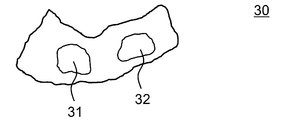
- “Number of regions” is, for example, “region surrounded by cracks”, and a small unit in which no region surrounded by cracks is further formed is defined as one region. However, if there are n small regions that do not share a crack in the “region surrounded by cracks”, the number is (n + 1) regions. Specifically, in the case of the region 20 shown in FIG.
- the “number of regions” in this example is There are three. In this example, it can be said that the small units 21 and 22 (or 22 and 23, or 21, 22, and 23) form one region. However, since these regions are not small units, It is not included in the “number of regions” in the embodiment. On the other hand, in the case of the region 30 shown in FIG. 3, there are two small regions 31 and 32 that do not share a crack surrounding the region 30, and therefore, the “number of regions” in this example is three.
- the average number density of the regions on the rake face or the flank face can be obtained by the following method. That is, the number density of the regions can be obtained by measuring the number of regions observed on the polished surface of the Ti compound layer and dividing the measured number of regions by the area of the measured Ti compound layer. And the number density of each area
- the rake face, the average number density of the area observed on the polished surface of the Ti compound layer and A r, the flank, the mean number density of the area observed on the polished surface of the Ti compound layer and A f, below, Ar and A f are collectively referred to as A.
- intermittent crack refers to a crack that surrounds a region and a crack that does not contact at one or both ends.
- the mode of the intermittent crack is, for example, a mode in which no crack is in contact with the region, a crack progresses from the crack surrounding the region toward the inside of the region, but progresses in the middle without crossing the region. The aspect which has stopped is mentioned.
- the average number density of intermittent cracks on the rake face or flank face can be obtained by the following method. That is, the number of interrupted cracks observed on the polished surface of the Ti compound layer is measured, and the number of interrupted cracks measured is divided by the measured area of the Ti compound layer, whereby the number density of interrupted cracks is obtained. Each number density of the measured visual fields is summed, and the average number density is obtained by dividing the total of each number density by the number of measured visual fields.
- the rake face, the average number density of intermittent cracks observed on the polished surface of the Ti compound layer and B r, in the flank, the mean number density of the intermittent cracks observed on the polished surface of the Ti compound layer and B f, Br and Bf are collectively referred to as B.
- the Ti compound layer includes at least one TiCN layer because the wear resistance is further improved.
- the average particle size of the TiCN layer is 0.3 ⁇ m or more, the chipping resistance tends to be further improved.
- the average particle size of the TiCN layer is 2.0 ⁇ m or less, the wear resistance on the flank surface tends to be further improved.
- the average particle size of the TiCN layer is preferably 0.3 ⁇ m or more and 2.0 ⁇ m or less from the viewpoint of further improving the fracture resistance and wear resistance in a balanced manner. From the same viewpoint, the average particle size of the TiCN layer is more preferably 0.3 ⁇ m or more and 1.5 ⁇ m or less.
- the average particle size of the TiCN layer can be obtained by the following method. That is, the coated cutting tool is heated at 1200 ° C. for 10 minutes in a vacuum, and the binder phase component of the cemented carbide base material is diffused into the grain boundaries of the TiCN layer. Thereafter, the mirror-polished surface of the cross section in the orthogonal direction of the coated cutting tool is observed with a scanning electron microscope (SEM), and a photograph is taken. At this time, it is preferable to observe a backscattered electron image of 5000 to 20000 times.
- SEM scanning electron microscope
- a straight line is drawn in a parallel direction with respect to the interface between the cemented carbide base material and the coating layer, and the number of grain boundaries of the TiCN layer crossing the straight line is measured.
- the average particle size of the TiCN layer is calculated.
- the straight line may be drawn at a position of 40% or more and 60% of the average thickness of the TiCN layer.
- the wear resistance tends to be further improved. It is in.
- the atomic ratio [C / (C + N)] is 0.75 or less, the fracture resistance tends to be further improved.
- the atomic ratio [C / (C + N)] is preferably 0.50 or more and 0.75 or less. From the same viewpoint, the atomic ratio [C / (C + N)] is more preferably 0.50 or more and 0.70 or less.
- the atomic ratio [C / (C + N)] of carbon to the total of carbon and nitrogen contained in the TiCN layer is, for example, the amount of C in the TiCN layer by an electron probe microanalyzer (EPMA). And N amount.
- the coating layer includes an aluminum oxide layer (hereinafter referred to as “Al 2 O 3 layer”) on the surface of the Ti compound layer
- Al 2 O 3 layer an aluminum oxide layer
- the crystal type of the Al 2 O 3 layer is not particularly limited, and examples include ⁇ -type, ⁇ -type, ⁇ -type, ⁇ -type, ⁇ -type, ⁇ -type, pseudo- ⁇ -type, ⁇ -type, and ⁇ -type.
- the crystal type of the Al 2 O 3 layer is preferably ⁇ type from the viewpoint of being more stable even at high temperatures, and from the viewpoint of further improving the adhesion between the Ti compound layer and the Al 2 O 3 layer.
- the ⁇ type is preferred.
- the Al 2 O 3 layer is an ⁇ -type Al 2 O 3 layer because defects and chipping are less likely to occur.
- the average thickness of the Al 2 O 3 layer is 1.0 ⁇ m or more, the crater wear resistance on the rake face tends to be further improved.
- the average thickness of the Al 2 O 3 layer is 15.0 ⁇ m or less, the fracture resistance tends to be further improved.
- the average thickness of the Al 2 O 3 layer is preferably 1.0 ⁇ m or more and 15.0 ⁇ m or less, from the same viewpoint. More preferably, it is 3.0 ⁇ m or more and 12.0 ⁇ m or less, and further preferably 5.0 ⁇ m or more and 12.0 ⁇ m or less.
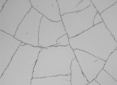
- FIG. 4 shows an example of a photograph of the polished surface substantially parallel to the surface of the rake face of the substrate in the Ti compound layer of the present embodiment viewed from above, and the flank of the substrate in the Ti compound layer of the present embodiment.
- An example of a photograph of a polished surface substantially parallel to the surface viewed from the top is shown in FIG.
- each layer constituting the coating layer in the coated cutting tool of the present embodiment for example, the following method can be exemplified.
- the TiN layer When the TiN layer is included in the Ti compound layer, for example, the TiN layer has a raw material gas composition of TiCl 4 : 3.0 to 10.0 mol%, N 2 : 20 to 60 mol%, H 2 : the balance, and temperature: It can be formed by chemical vapor deposition at 850 to 920 ° C. and pressure: 100 to 350 hPa.
- the TiCN layer When the TiCN layer is included in the Ti compound layer, for example, the TiCN layer has a raw material gas composition of TiCl 4 : 10 to 15 mol%, CH 3 CN: 1 to 3 mol%, N 2 : 0 to 20 mol%, H 2 : The remainder can be formed by chemical vapor deposition at a temperature of 850 to 920 ° C. and a pressure of 60 to 80 hPa.
- C / (C + N) in the TiCN layer can be adjusted only to less than 0.65.
- the raw material gas composition is TiCl 4 : 1.0 to 8.0 mol%, CH 3 CN: 1.0 to 2.0 mol %, C 3 H 6 : 1.0 to 2.0 mol%, N 2 : 10 to 50 mol%, H 2 : balance, temperature: 700 to 900 ° C., pressure: 50 to 100 hPa. be able to.
- the TiC layer When the TiC layer is included in the Ti compound layer, the TiC layer has, for example, a raw material gas composition of TiCl 4 : 1.0 to 3.0 mol%, CH 4 : 4.0 to 6.0 mol%, H 2 : balance And a temperature of 990 to 1030 ° C. and a pressure of 50 to 100 hPa.
- the ⁇ -type Al 2 O 3 layer has a raw material gas composition of AlCl 3 : 2.1 to 5.0 mol%, CO 2 : 2. 5 to 4.0 mol%, HCl: 2.0 to 3.0 mol%, H 2 S: 0.28 to 0.45 mol%, H 2 : balance, temperature: 900 to 1000 ° C., pressure: 60 to 80 hPa It can be formed by chemical vapor deposition.
- the ⁇ -type Al 2 O 3 layer has, for example, a material gas composition of AlCl 3 : 2.1 to 5.0 mol%, CO 2 : 2. 0 to 6.0 mol%, CO: 3.0 to 5.5 mol%, HCl: 3.0 to 5.0 mol%, H 2 S: 0.3 to 0.5 mol%, H 2 : remainder, temperature: It can be formed by chemical vapor deposition at 900 to 1000 ° C. and pressure: 60 to 80 hPa.
- the TiAlCNO layer has, for example, a raw material gas composition of TiCl 4 : 3.0 to 5.0 mol%, AlCl 3 : 1.0 to 2.0 mol%, CO: 0.00. It can be formed by chemical vapor deposition using 4 to 1.0 mol%, N 2 : 30 to 40 mol%, H 2 : balance, temperature: 975 to 1025 ° C., and pressure: 90 to 120 hPa.
- the TiAlCO layer has, for example, a material gas composition of TiCl 4 : 0.5 to 1.5 mol%, AlCl 3 : 3.0 to 5.0 mol%, CO: 2. It can be formed by a chemical vapor deposition method with 0 to 4.0 mol%, H 2 : the balance, temperature: 975 to 1025 ° C., and pressure: 60 to 100 hPa.
- the TiCNO layer has, for example, a raw material gas composition of TiCl 4 : 3.0 to 5.0 mol%, CO: 0.4 to 1.0 mol%, N 2 : 30 to It can be formed by chemical vapor deposition with 40 mol%, H 2 : balance, temperature: 975 to 1025 ° C., and pressure: 90 to 110 hPa.
- the TiCO layer When the TiCO layer is included in the Ti compound layer, for example, the TiCO layer has a raw material gas composition of TiCl 4 : 0.5 to 1.5 mol%, CO: 2.0 to 4.0 mol%, H 2 : balance. , Temperature: 975 to 1025 ° C., pressure: 60 to 100 hPa.
- a coated cutting tool that satisfies the relationship between the average number density of regions and the average number density of intermittent cracks in each Ti compound layer on the rake face and the flank face can be obtained by, for example, the following method.
- the average number density B of intermittent cracks in the Ti compound layer can be easily controlled.
- the aspect ratio of the projection material is preferably 1.5 or more and 3.0 or less, and more preferably, the projection material has a sharp convex portion.
- the dry shot blasting conditions are such that the projection angle is 80 ° to 90 ° with respect to the surface of the rake face coating layer, and the projection material is 80 m / sec to The projection may be performed at a projection speed of 100 m / sec and a projection time of 0.5 minutes to 1.0 minutes.
- the dry shot blasting projection material is preferably made of a material such as Al 2 O 3 or ZrO 2 having an average particle diameter of 160 ⁇ m to 200 ⁇ m.
- dry shot blasting conditions are such that the projection angle is 80 ° to 90 ° with respect to the surface of the flank coating layer, and the projection material is 40 to 60 m / sec. It is better to project at a projection speed of 0.5 to 1.0 minutes.
- the dry shot blasting projection material is preferably made of a material such as Al 2 O 3 or ZrO 2 having an average particle size of 100 to 140 ⁇ m. At this time, the form of cracks can be easily controlled by masking the surface not subjected to dry shot blasting.
- the aspect ratio of the projection material is a value obtained by dividing the maximum diameter value of the projection material by the minimum diameter value.
- the average particle diameter of the projection material is an average value of the maximum diameter value and the minimum diameter value in the projection material.
- the projection angle is an angle formed by the surface of the coating layer and the angle at which the projection material is projected. Therefore, when dry shot blasting is applied to the rake face, it refers to the angle formed by the surface of the coating layer of the rake face and the angle at which the projection material is projected.When dry shot blasting is applied to the flank face, It refers to the angle between the surface of the coating layer and the angle at which the projection material is projected.
- the thickness of each layer can be measured from the cross-sectional structure of the coated cutting tool using an optical microscope, SEM, field emission scanning electron microscope (FE-SEM) or the like.
- the thickness of the coated cutting tool may be determined by measuring three or more thicknesses of each layer at a position in the vicinity of 50 ⁇ m from the cutting edge toward the rake face of the coated cutting tool, and obtaining an average value thereof.
- the composition of each layer can be measured from the cross-sectional structure of the coated cutting tool of the present embodiment using an energy dispersive X-ray spectrometer (EDS), a wavelength dispersive X-ray spectrometer (WDS), or the like.
- EDS energy dispersive X-ray spectrometer
- WDS wavelength dispersive X-ray spectrometer
- Examples of the method for measuring the average number density in the region of the Ti compound layer and the intermittent cracks include the following methods.
- the coated cutting tool is polished in a direction substantially parallel to the surface of the substrate until the surface or the inside of the Ti compound layer is exposed to obtain a polished surface of the Ti compound layer.
- the polished surface is etched with hydrofluoric acid, cracks can be easily observed.
- the polished surface is observed at 300 to 750 times using an optical microscope, and a photograph of the polished surface is taken. Using this photograph of the polished surface, the number of Ti compound layer regions and the number of intermittent cracks are measured. By dividing the number of measured regions and the number of intermittent cracks by the measured area, the number density of the regions and intermittent cracks can be obtained.
- the total number density of the areas of each visual field and the number of interrupted cracks is summed and divided by the number of measured fields of view, respectively, to obtain the average number density A of the areas and the average number density B of the intermittent cracks. It is preferable to measure a range of 0.2 mm 2 or more using a photograph of the polished surface, more preferably to measure a range of 0.25 mm 2 or more, and further to measure a range of 0.3 mm 2 or more. preferable.
- the region in which it is not possible to confirm whether or not the region has been formed due to the break of the crack at the end of the photograph is 0.5 region.
- the average number density A of regions and the average number density B of interrupted cracks on the rake face and flank face can be obtained by the measurement method described above.
- a cemented carbide cutting insert of 86.0WC-1.0TiCN-1.0TaC-0.5NbC-0.5ZrC-11.0Co (more than by mass) composition having a JIS standard CNMG120212 shape was prepared as a base material.
- the surface of the base material was cleaned after round honing was performed on the cutting edge ridge line portion of the base material with a SiC brush.
- the base material is inserted into an external heating chemical vapor deposition apparatus, and the coating layer is formed on the surface of the base material so as to have the composition and average thickness of the coating layer shown in Table 3 under the film forming conditions shown in Table 1. Formed.
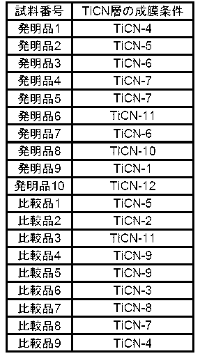
- the TiCN layer of each sample was formed under the film forming conditions shown in Table 2.
- the TiCN layer deposition conditions shown in Table 2 correspond to the types of coating layers shown in Table 1. Ten samples were prepared each. ⁇ in the crystal form of the aluminum oxide layer (Al 2 O 3 layer) shown in Table 3 represents an ⁇ -type Al 2 O 3 layer, and ⁇ represents a ⁇ -type Al 2 O 3 layer.
- each layer of the obtained sample was measured with three SEM cross sections near the position of 50 ⁇ m from the cutting edge of the coated cutting tool toward the center of the rake face, and the average value (arithmetic average value) was measured. Asked.
- the obtained sample was polished until the Ti compound layer was exposed in a direction substantially parallel to the surface of the substrate. At this time, a rake face and a flank polished face were prepared.
- the polished surface of the Ti compound layer was adjusted to a position where 70% of the average thickness of the Ti compound layer remained, and the polished surface of the Ti compound layer was etched with hydrofluoric acid.
- the polished surface of the Ti compound layer was observed at 300 times using an optical microscope, and a photograph of the polished surface in the range of 0.33 mm 2 was taken.
- the atomic ratio [C / (C + N)] of C with respect to the total of C and N contained in the TiCN layer of the obtained sample is about 50 ⁇ m from the edge of the coated cutting tool toward the center of the rake face. It measured using EPMA from the cross section. The results obtained are shown in Table 6.
- the obtained sample is held at 1200 ° C. for 10 minutes in a vacuum and heat-treated to diffuse the binder phase component of the cemented carbide substrate into the grain boundaries of the TiCN layer, and then the vertical section of the coated cutting tool.
- the mirror polished surface was observed with an SEM, and a photograph was taken.
- draw a straight line in a parallel direction with respect to the interface between the cemented carbide base material and the coating layer and measure the number of grain boundaries of the TiCN layer across the straight line.
- the average particle size of the TiCN layer was calculated. At this time, a straight line was drawn at a position of 50% of the average thickness of the TiCN layer. The results obtained are shown in Table 7.
- the coated cutting tool of the present invention can improve wear resistance without impairing chipping resistance and chipping resistance, and can extend the tool life as compared with the prior art. High availability on.
- SYMBOLS 1 Base material, 2 ... Coating layer, 3 ... Rake face, 4 ... Flank face, 5 ... Cutting edge ridge part, 11 ... Ti compound layer, 12 ... Aluminum oxide layer, 20, 30 ... Area, 21-23 ... Small Units 31, 32 ... small area, 100 ... coated cutting tool.
Landscapes
- Chemical & Material Sciences (AREA)
- Engineering & Computer Science (AREA)
- Mechanical Engineering (AREA)
- Inorganic Chemistry (AREA)
- General Chemical & Material Sciences (AREA)
- Chemical Kinetics & Catalysis (AREA)
- Materials Engineering (AREA)
- Metallurgy (AREA)
- Organic Chemistry (AREA)
- Cutting Tools, Boring Holders, And Turrets (AREA)
- Chemical Vapour Deposition (AREA)
- Drilling Tools (AREA)
Abstract
基材と、前記基材の表面に形成された被覆層とを備える被覆切削工具であって、 前記被覆切削工具は、すくい面と、逃げ面と、すくい面と逃げ面との間に切刃稜線部とを有し、 前記被覆層が、少なくとも1層のTi化合物層を含み、 前記Ti化合物層が、TiまたはTiおよびAlと、C、N、OおよびBから成る群より選ばれる少なくとも1種の元素とを含む化合物層であり、 前記Ti化合物層における、前記基材の表面と略平行な研磨面を上面から見たとき、前記Ti化合物層はクラックによって囲まれた領域を有し、 前記領域の内側に、前記領域を囲む前記クラックと、一端または両端で接しない断続クラックを有し、 前記すくい面の少なくとも一部において、前記領域の平均数密度Arと前記断続クラックの平均数密度Brとが0.7<Br/Ar<4.0を満たし、 前記逃げ面の少なくとも一部において、前記領域の平均数密度Afと前記断続クラックの平均数密度Bfとが0.1<Bf/Af<1.5を満たし、 かつ、Br/Ar>Bf/Afである、被覆切削工具。
Description
本発明は、被覆切削工具に関するものである。
従来、超硬合金からなる基材の表面に、例えばTiの炭化物、窒化物、炭窒化物、炭酸化物および炭窒酸化物、並びに酸化アルミニウムの中の1種の単層または2種以上の複層からなる被覆層を、化学蒸着法により3~20μmの総膜厚で蒸着形成してなる被覆切削工具が、鋼や鋳鉄などの切削加工に用いられていることは良く知られている。
通常、炭化タングステン基超硬合金の表面に被膜を形成すると、被膜に引張応力が残留するために、被覆切削工具の破壊強度が低下して欠損し易くなるとされている。これまで、被膜形成後ショットピーニング等を行い、クラックを発生させることにより、引張残留応力を開放することが提案され、かなりの効果が得られている(例えば、特許文献1参照)。
Ti化合物層において、クラックに囲まれた領域と、前記領域の内側に、クラックの一端または前記領域を構成するクラックと接しない断続クラックを有する切削工具が提案されている(例えば、特許文献2参照)。
近年の切削加工では、高速化、高送り化および深切込み化が顕著となり、従来よりも工具寿命が低下する傾向にある。このような背景において、特許文献1に開示された工具であっても、単純に被膜のクラックを増加させると、耐欠損性は向上するが、クラックを起点とした被膜の耐剥離性、耐チッピング性および耐摩耗性は低下する。また、特許文献2で開示された被覆切削工具については、このような背景によりさらなる耐摩耗性の向上が求められる。本発明は、これらの問題を解決するためになされたものであり、被覆切削工具のクラック発生形態を工夫することにより、優れた耐チッピング性、耐摩耗性および耐欠損性を有し、工具寿命の長い被覆切削工具を提供することを目的とする。
本発明者らは、上述の観点から、被覆切削工具の工具寿命の延長について研究を重ねたところ、逃げ面における断続クラックの数密度が高いと、加工時の被削材と被覆切削工具とのこすれによるこすれ摩耗が生じることを見出した。そして、そのこすれ摩耗に起因して、逃げ面のTi化合物層の粒子が脱落する結果、耐摩耗性が十分ではないことを見出した。本発明者らは、この知見を踏まえて、以下の構成にすると、耐チッピング性および耐欠損性を損なうことなく、耐摩耗性を向上させることができ、その結果、工具寿命を延長することができるという知見を得た。
すなわち、本発明の要旨は以下の通りである。
(1)
基材と、前記基材の表面に形成された被覆層とを備える被覆切削工具であって、
前記被覆切削工具は、すくい面と、逃げ面と、すくい面と逃げ面との間に切刃稜線部とを有し、
前記被覆層が、少なくとも1層のTi化合物層を含み、
前記Ti化合物層が、TiまたはTiおよびAlと、C、N、OおよびBから成る群より選ばれる少なくとも1種の元素とを含む化合物層であり、
前記Ti化合物層における、前記基材の表面と略平行な研磨面を上面から見たとき、前記Ti化合物層はクラックによって囲まれた領域を有し、
前記領域の内側に、前記領域を囲む前記クラックと、一端または両端で接しない断続クラックを有し、
前記すくい面の少なくとも一部において、前記領域の平均数密度Arと前記断続クラックの平均数密度Brとが0.7<Br/Ar<4.0を満たし、
前記逃げ面の少なくとも一部において、前記領域の平均数密度Afと前記断続クラックの平均数密度Bfとが0.1<Bf/Af<1.5を満たし、
かつ、Br/Ar>Bf/Afである、被覆切削工具。
(2)
前記すくい面の少なくとも一部において、前記領域の平均数密度Arと前記断続クラックの平均数密度Brとが1.2<Br/Ar<3.0を満たし、
前記逃げ面の少なくとも一部において、前記領域の平均数密度Afと前記断続クラックの平均数密度Bfとが0.1<Bf/Af<1.2を満たす、(1)に記載の被覆切削工具。
(3)
前記Ti化合物層が、前記基材の表面に形成され、平均厚さが2.0μm以上20.0μm以下である、(1)または(2)のいずれかの被覆切削工具。
(4)
前記Ti化合物層が、少なくとも1層のTiCN層を含み、
前記TiCN層の平均粒径は、0.3μm以上2.0μm以下である、(1)~(3)のいずれかの被覆切削工具。
(5)
前記TiCN層に含まれる炭素と窒素との合計に対する炭素の原子比[C/(C+N)]が0.50以上0.75以下である、(4)の被覆切削工具。
(6)
前記被覆層が、前記Ti化合物層の表面に、平均厚さが1.0μm以上15.0μm以下の酸化アルミニウム層を有する、(1)~(5)のいずれかの被覆切削工具。
(7)
前記被覆層の全体の平均厚さが3.0μm以上30.0μm以下である、(1)~(6のいずれかの被覆切削工具。
(8)
前記基材が、超硬合金、サーメット、セラミックスまたは立方晶窒化硼素焼結体のいずれかである、(1)~(7)のいずれかの被覆切削工具。
(1)
基材と、前記基材の表面に形成された被覆層とを備える被覆切削工具であって、
前記被覆切削工具は、すくい面と、逃げ面と、すくい面と逃げ面との間に切刃稜線部とを有し、
前記被覆層が、少なくとも1層のTi化合物層を含み、
前記Ti化合物層が、TiまたはTiおよびAlと、C、N、OおよびBから成る群より選ばれる少なくとも1種の元素とを含む化合物層であり、
前記Ti化合物層における、前記基材の表面と略平行な研磨面を上面から見たとき、前記Ti化合物層はクラックによって囲まれた領域を有し、
前記領域の内側に、前記領域を囲む前記クラックと、一端または両端で接しない断続クラックを有し、
前記すくい面の少なくとも一部において、前記領域の平均数密度Arと前記断続クラックの平均数密度Brとが0.7<Br/Ar<4.0を満たし、
前記逃げ面の少なくとも一部において、前記領域の平均数密度Afと前記断続クラックの平均数密度Bfとが0.1<Bf/Af<1.5を満たし、
かつ、Br/Ar>Bf/Afである、被覆切削工具。
(2)
前記すくい面の少なくとも一部において、前記領域の平均数密度Arと前記断続クラックの平均数密度Brとが1.2<Br/Ar<3.0を満たし、
前記逃げ面の少なくとも一部において、前記領域の平均数密度Afと前記断続クラックの平均数密度Bfとが0.1<Bf/Af<1.2を満たす、(1)に記載の被覆切削工具。
(3)
前記Ti化合物層が、前記基材の表面に形成され、平均厚さが2.0μm以上20.0μm以下である、(1)または(2)のいずれかの被覆切削工具。
(4)
前記Ti化合物層が、少なくとも1層のTiCN層を含み、
前記TiCN層の平均粒径は、0.3μm以上2.0μm以下である、(1)~(3)のいずれかの被覆切削工具。
(5)
前記TiCN層に含まれる炭素と窒素との合計に対する炭素の原子比[C/(C+N)]が0.50以上0.75以下である、(4)の被覆切削工具。
(6)
前記被覆層が、前記Ti化合物層の表面に、平均厚さが1.0μm以上15.0μm以下の酸化アルミニウム層を有する、(1)~(5)のいずれかの被覆切削工具。
(7)
前記被覆層の全体の平均厚さが3.0μm以上30.0μm以下である、(1)~(6のいずれかの被覆切削工具。
(8)
前記基材が、超硬合金、サーメット、セラミックスまたは立方晶窒化硼素焼結体のいずれかである、(1)~(7)のいずれかの被覆切削工具。
本発明の被覆切削工具は、耐チッピング性および耐欠損性を損なうことなく、耐摩耗性を向上させることができるので、従来よりも工具寿命を延長できるという効果を奏する。
以下、本発明を実施するための形態(以下、単に「本実施形態」という。)について詳細に説明するが、本発明は下記本実施形態に限定されるものではない。本発明は、その要旨を逸脱しない範囲で様々な変形が可能である。
本実施形態の被覆切削工具は、基材とその基材の表面に形成された被覆層とを含む。被覆切削工具は、すくい面と、逃げ面と、すくい面と逃げ面との間に切刃稜線部とを有する。被覆切削工具の種類として具体的には、フライス加工用または旋削加工用刃先交換型切削インサート、ドリル、及びエンドミルが挙げられる。
図1は、本実施形態の被覆切削工具の一態様を示す模式断面図である。被覆切削工具100は、基材1と、基材1の表面に形成された被覆層2とを含み、すくい面3と、逃げ面4と、すくい面3と逃げ面4との間に切刃稜線部5とを有する。被覆層2は、後述するTi化合物層11及び酸化アルミニウム層12がこの順序で基材1の表面に積層された二層である。
本実施形態における基材は、被覆切削工具の基材として用いられ得るものであれば、特に限定されない。基材としては、超硬合金、サーメット、セラミックス、立方晶窒化硼素焼結体、ダイヤモンド焼結体、および高速度鋼からなる群より選択される少なくとも1種が挙げられる。これらの中でも、基材が、超硬合金、サーメット、セラミックスおよび立方晶窒化硼素焼結体からなる群より選択される少なくとも1種であると、被覆切削工具の耐摩耗性および耐欠損性がより一層優れるので、さらに好ましい。
これらの基材は、基材の表面が改質されたものであってもよい。例えば、基材が超硬合金である場合には、基材の表面に脱β層が形成されていてもよく、基材がサーメットである場合には、表面硬化層が形成されていてもよい。このように基材の表面が改質されていても、本発明の作用効果が発揮できる。
本実施形態の被覆切削工具において、被覆層全体の平均厚さが3.0μm以上であると、耐摩耗性がより一層向上する傾向にある。一方、被覆層全体の平均厚さが30.0μm以下であると、耐欠損性がより一層向上する傾向にある。このため、耐摩耗性および耐欠損性をバランスよくより一層向上する観点から、被覆層の全体の平均厚さは、3.0μm以上30.0μm以下であることが好ましく、同様の観点から、3.2μm以上25.0μm以下であることがより好ましく、3.4μm以上22.0μm以下であることがさらに好ましく、3.5μm以上18.0μm以下であることが特に好ましい。
本実施形態の被覆切削工具において、被覆層は、少なくとも1層のTi化合物層を含む。Ti化合物層は、Ti元素またはTi元素とAl元素とを含み、さらに、C、N、OおよびBからなる群より選択される少なくとも1種の元素を含む化合物層であり、Ti元素またはTi元素とAl元素とを含み、さらに、C、N、およびOからなる群より選択される少なくとも1種の元素を含むことが好ましい。Ti化合物層としては、例えば、TiC層、TiN層、TiCN層、TiCO層、TiCNO層、TiAlCO層及びTiAlCNO層が挙げられる。Ti化合物層は、1層で構成されてもよく、複層(例えば、2層又は3層)で構成されてもよい。Ti化合物層が2層で構成されている場合には、基材の表面に、TiC層またはTiN層を第1層として形成し、第1層の表面に、TiCN層を第2層として形成してもよい。Ti化合物層が3層で構成されている場合には、上記第1層および第2層に加えて、第2層の表面に、TiCO層、TiCNO層、TiAlCO層、またはTiAlCNO層を第3層として形成してもよい。
本実施形態の被覆切削工具において、Ti化合物層が基材の表面に形成されると、基材と被覆層との密着性がより一層向上するため好ましい。また、Ti化合物層の平均厚さが2.0μm以上であると、耐摩耗性がより一層向上する傾向にある。一方、Ti化合物層の平均厚さが20.0μm以下であると、耐欠損性がより一層向上する傾向にある。このため、Ti化合物層の平均厚さは、2.0μm以上20.0μm以下であることが好ましく、同様の観点から、3.0μm以上15.0μm以下であることがより好ましく、4.0μm以上14.0μm以下であることがさらに好ましい。なお、ここでいう「Ti化合物層の平均厚さ」とは、Ti化合物層が1層で構成されている場合には、1層の平均厚さをいい、Ti化合物層が複層で構成されている場合には、Ti化合物層全体の平均厚さをいう。
本実施形態の被覆切削工具において、Ti化合物層は、基材の表面と略平行な研磨面を上面から見たとき、Ti化合物層にはクラックによって囲まれた領域を有し、領域の内側には、領域を囲むクラックと、一端または両端で接しない断続クラックを有する。ここで、「上面から見た」とは、Ti化合物層の研磨面を面の略法線方向から見たことを意味する。別の言い方をすれば、被覆層表面を研磨する前において被覆層の表面側から見た場合、つまり基材の反対側から見た場合を意味する。
本実施形態の被覆切削工具において、すくい面の少なくとも一部における、領域の平均数密度Arと断続クラックの平均数密度Brとが0.7<Br/Ar<4.0を満たすことにより、切削中に被覆層に発生した亀裂の進展を断続クラックで止める効果が得られるので、耐チッピング性および耐欠損性が優れる。Br/Arが0.7を超えると、断続クラックが十分に分布しているため、切削中に被覆層に発生した亀裂の進展を断続クラックで止める効果が得られる。これにより、耐チッピング性および耐欠損性が向上する。一方、Br/Arが4.0未満であると、領域を囲むクラックと断続クラックとがつながりやすくなるのを防ぐことができる。これにより、被覆切削工具は、耐欠損性の低下を抑制することができる。同様の観点から、Br/Arは、0.9<Br/Ar<3.5であることがより好ましく、1.2<Br/Ar<3.0であることがさらに好ましい。
本実施形態の被覆切削工具において、逃げ面の少なくとも一部における、領域の平均数密度Afと断続クラックの平均数密度Bfとが0.1<Bf/Af<1.5を満たすことにより、逃げ面のTi化合物層の粒子が脱落することを抑制できる。これにより、切削時の被削材と被覆切削工具とのこすれによるこすれ摩耗を抑制できるので、被覆切削工具は、耐摩耗性に優れる。Bf/Afが0.1を超えると、断続クラックが適度に分布することに起因して、切削中に被覆層に発生した亀裂の進展を断続クラックで止める効果が得られる。これにより、被覆切削工具の耐チッピング性および耐欠損性が向上する。一方、Bf/Afが1.5未満であると、逃げ面のこすれ摩耗を抑制することができるので、被覆切削工具は、耐摩耗性に優れる。同様の観点から、Bf/Afは、0.1<Bf/Af<1.3であることがより好ましく、0.1<Bf/Af<1.2であることがさらに好ましい。
本実施形態の被覆切削工具は、Br/Arと、Bf/Afとが、Br/Ar>Bf/Afの関係にあると、切削中に被覆層に発生した亀裂を断続クラックで止める効果と、逃げ面のこすれ摩耗を抑制する効果とのバランスに優れる。これにより、被覆切削工具は、耐摩耗性、耐チッピング性および耐欠損性に優れる。
上記と同様の観点から、すくい面の少なくとも一部における、領域の平均数密度Arと断続クラックの平均数密度Brとが1.2<Br/Ar<3.0を満たし、逃げ面の少なくとも一部における、領域の平均数密度Afと断続クラックの平均数密度Bfとが0.1<Bf/Af<1.2を満たすことが好ましい。
Ti化合物層の研磨面とは、例えば、被覆切削工具において、すくい面または逃げ面の少なくとも一部における、基材の表面と略平行な方向にTi化合物層の表面又は内部が露出するまで研磨して得られたTi化合物層の面である。このとき、Ti化合物層の平均厚さの50%以上の厚さが残るような位置で研磨面を得るのが好ましい。なお、複数の組成のTi化合物層が形成されている被覆切削工具は、最も平均厚さが厚い組成の層の領域および断続クラックを測定するのが好ましい。
本実施形態の被覆切削工具において、すくい面または逃げ面における、Ti化合物層の研磨面に観察される領域とは、被覆層を形成した後の冷却時に被覆層中に発生するクラックおよび乾式ブラストやショットピーニングなどの加工によって被覆層中に生じるクラックによって囲まれた範囲である。「領域の個数」は、例えば、「クラックで囲まれた領域」であって、この領域の中に、クラックで囲まれた領域がさらに形成されていない小単位を1つの領域とする。但し、「クラックで囲まれた領域」の中に、クラックを共有しない小さい領域がn個存在する場合には、(n+1)個の領域とする。具体的には、図2に示す領域20の場合には、領域20の中に、クラックで囲まれた小単位21~23が3つ存在しているので、この例における「領域の個数」は3つである。なお、この例では、小単位21と22(もしくは22と23、又は21、22、及び23)とで1つの領域を形成しているともいえるが、これらの領域は小単位ではないため、本実施形態にいう「領域の個数」に含まれない。一方、図3に示す領域30の場合には、領域30を囲むクラックを共有しない2個の小さい領域31,32が存在しているため、この例における「領域の個数」は3つである。
本実施形態の被覆切削工具において、すくい面または逃げ面における、領域の平均数密度は、以下の方法で求めることができる。すなわち、Ti化合物層の研磨面に観察される領域の個数を測定し、測定した領域の個数を、測定したTi化合物層の面積で割ると、領域の数密度を求めることができる。そして、測定した視野の各領域の数密度を合計し、各領域の数密度の合計を、測定した視野の数で割ると、平均数密度が求められる。すくい面における、Ti化合物層の研磨面に観察される領域の平均数密度をArとし、逃げ面における、Ti化合物層の研磨面に観察される領域の平均数密度をAfとし、以下、ArおよびAfをまとめてAとする。
本明細書にいう「断続クラック」とは、領域を囲むクラックと、一端または両端で接しないクラックをいう。断続クラックの態様は、例えば、領域の中にいずれのクラックとも接していない態様、領域を囲むクラックから領域の内側に向かってクラックが進展しているが、領域を横断せずに途中で進展が停止している態様が挙げられる。
本実施形態の被覆切削工具において、すくい面または逃げ面における、断続クラックの平均数密度は、以下の方法で求めることができる。すなわち、Ti化合物層の研磨面に観察される断続クラックの個数を測定し、測定した断続クラックの個数を、測定したTi化合物層の面積で割ると、断続クラックの数密度が求められる。測定した視野の各数密度を合計し、各数密度の合計を、測定した視野の数で割ると、平均数密度が求められる。すくい面における、Ti化合物層の研磨面に観察される断続クラックの平均数密度をBrとし、逃げ面における、Ti化合物層の研磨面に観察される断続クラックの平均数密度をBfとし、BrおよびBfをまとめてBとする。
本実施形態の被覆切削工具において、Ti化合物層は、少なくとも1層のTiCN層を含むと、耐摩耗性がより一層向上するため、好ましい。TiCN層の平均粒径が0.3μm以上であると、耐欠損性がより一層向上する傾向にある。一方、TiCN層の平均粒径が2.0μm以下であると、逃げ面における耐摩耗性がより一層向上する傾向がみられる。このため、TiCN層の平均粒径は、耐欠損性および耐摩耗性をバランスよくより一層向上する観点から、0.3μm以上2.0μm以下であることが好ましい。同様の観点から、TiCN層の平均粒径は0.3μm以上1.5μm以下であることがより好ましい。
本実施形態の被覆切削工具において、TiCN層の平均粒径は、以下の方法により、求めることができる。すなわち、被覆切削工具を真空中にて1200℃で10分間保持して加熱処理し、TiCN層の結晶粒界に超硬合金基材の結合相の成分を拡散させる。その後、被覆切削工具の直交方向の断面の鏡面研磨面を走査型電子顕微鏡(SEM)で観察し、写真を撮影する。このとき、5000倍~20000倍の反射電子像を観察するとよい。撮影したTiCN層の写真の中央部分で超硬合金の基材と被覆層との界面に対して、平行な方向に直線を引き、この直線を横切るTiCN層の粒界の数を測定して、TiCN層の平均粒径を算出する。直線は、TiCN層の平均厚さの40%以上60%の位置に引くとよい。
本実施形態の被覆切削工具において、TiCN層に含まれる炭素と窒素の合計に対する炭素の原子比[C/(C+N)]が、0.50以上であると、耐摩耗性がより一層向上する傾向にある。一方、原子比[C/(C+N)]が0.75以下であると、耐欠損性がより一層向上する傾向にある。このため、耐摩耗性および耐欠損性をバランスよくより一層向上する観点から、原子比[C/(C+N)]は、0.50以上0.75以下であることが好ましい。同様の観点から、原子比[C/(C+N)]は0.50以上0.70以下であることがより好ましい。
本実施形態の被覆切削工具において、TiCN層に含まれる炭素と窒素の合計に対する炭素の原子比[C/(C+N)]は、例えば、電子プローブ微小分析器(EPMA)によりTiCN層中のC量とN量を定量することにより得られる。
本実施形態の被覆切削工具において、被覆層は、Ti化合物層の表面に酸化アルミニウム層(以下、「Al2O3層」という。)を含むと、被削材との反応による摩耗の進行を抑制することができるため好ましい。Al2O3層の結晶型は特に限定されず、α型、β型、δ型、γ型、κ型、χ型、擬τ型、η型、およびρ型が挙げられる。これらの中でも、Al2O3層の結晶型は、高温でもより一層安定である観点からα型であることが好ましく、Ti化合物層とAl2O3層との密着性がより一層優れる観点からκ型であることが好ましい。特に、高速切削など切削に関与する領域が高温になる場合において、Al2O3層がα型Al2O3層であると、欠損やチッピングを起こしにくくなるため好ましい。Al2O3層の平均厚さが1.0μm以上であると、すくい面における耐クレータ摩耗性がより一層向上する傾向にある。一方、Al2O3層の平均厚さが15.0μm以下であると、耐欠損性がより一層向上する傾向にある。このため、耐クレータ摩耗性および耐欠損性をバランスよくより一層向上する観点から、Al2O3層の平均厚さは、1.0μm以上15.0μm以下であることが好ましく、同様の観点から、3.0μm以上12.0μm以下であることがより好ましく、5.0μm以上12.0μm以下であることがさらに好ましい。
本実施形態のTi化合物層における、基材のすくい面の表面と略平行な研磨面を上面から見た写真の一例を図4に示し、本実施形態のTi化合物層における、基材の逃げ面表面と略平行な研磨面を上面から見た写真の一例を図5に示す。
本実施形態の被覆切削工具における被覆層を構成する各層の形成方法として、例えば、以下の方法を挙げることができる。
Ti化合物層にTiN層が含まれる場合、TiN層は、例えば、原料ガス組成を、TiCl4:3.0~10.0mol%、N2:20~60mol%、H2:残部とし、温度:850~920℃、圧力:100~350hPaとする化学蒸着法で形成することができる。
Ti化合物層にTiCN層が含まれる場合、TiCN層は、例えば、原料ガス組成を、TiCl4:10~15mol%、CH3CN:1~3mol%、N2:0~20mol%、H2:残部とし、温度:850~920℃、圧力:60~80hPaとする化学蒸着法で形成することができる。
なお、上記の方法では、TiCN層中のC/(C+N)を0.65未満までしか調整することができない。TiCN層のC/(C+N)を0.65~0.75にするために、例えば、原料ガス組成をTiCl4:1.0~8.0mol%、CH3CN:1.0~2.0mol%、C3H6:1.0~2.0mol%、N2:10~50mol%、H2:残部とし、温度:700~900℃、圧力:50~100hPaとする化学蒸着法で形成することができる。
このとき、TiCl4に対するCH3CNの原料ガス組成比[CH3CN/TiCl4]を小さくすると、TiCN層の平均粒径を小さくすることができる。また、温度を低くすると、TiCN層の平均粒径を小さくすることができる。
Ti化合物層にTiC層が含まれる場合、TiC層は、例えば、原料ガス組成を、TiCl4:1.0~3.0mol%、CH4:4.0~6.0mol%、H2:残部とし、温度:990~1030℃、圧力:50~100hPaとする化学蒸着法で形成することができる。
Al2O3層がα型Al2O3層である場合、α型Al2O3層は、例えば、原料ガス組成を、AlCl3:2.1~5.0mol%、CO2:2.5~4.0mol%、HCl:2.0~3.0mol%、H2S:0.28~0.45mol%、H2:残部とし、温度:900~1000℃、圧力:60~80hPaとする化学蒸着法で形成することができる。
Al2O3層がκ型Al2O3層である場合、κ型Al2O3層は、例えば、原料ガス組成を、AlCl3:2.1~5.0mol%、CO2:2.0~6.0mol%、CO:3.0~5.5mol%、HCl:3.0~5.0mol%、H2S:0.3~0.5mol%、H2:残部とし、温度:900~1000℃、圧力:60~80hPaとする化学蒸着法で形成することができる。
Ti化合物層にTiAlCNO層が含まれる場合、TiAlCNO層は、例えば、原料ガス組成を、TiCl4:3.0~5.0mol%、AlCl3:1.0~2.0mol%、CO:0.4~1.0mol%、N2:30~40mol%、H2:残部とし、温度:975~1025℃、圧力:90~120hPaとする化学蒸着法で形成することができる。
Ti化合物層にTiAlCO層が含まれる場合、TiAlCO層は、例えば、原料ガス組成を、TiCl4:0.5~1.5mol%、AlCl3:3.0~5.0mol%、CO:2.0~4.0mol%、H2:残部とし、温度:975~1025℃、圧力:60~100hPaとする化学蒸着法で形成することができる。
Ti化合物層にTiCNO層が含まれる場合、TiCNO層は、例えば、原料ガス組成を、TiCl4:3.0~5.0mol%、CO:0.4~1.0mol%、N2:30~40mol%、H2:残部とし、温度:975~1025℃、圧力:90~110hPaとする化学蒸着法で形成することができる。
Ti化合物層にTiCO層が含まれる場合、TiCO層は、例えば、原料ガス組成を、TiCl4:0.5~1.5mol%、CO:2.0~4.0mol%、H2:残部とし、温度:975~1025℃、圧力:60~100hPaとする化学蒸着法で形成することができる。
すくい面と逃げ面の各Ti化合物層における、領域の平均数密度および断続クラックの平均数密度の関係を満たす被覆切削工具は、例えば、以下の方法によって得られる。
被覆層を形成した後、従来よりもアスペクト比が大きい形状を有する投射材を用いて乾式ショットブラストを施すと、Ti化合物層中の断続クラックの平均数密度Bを容易に制御できる。投射材のアスペクト比が、1.5以上3.0以下であることが好ましく、投射材の形状が鋭利な凸部を有していることがさらに好ましい。すくい面のTi化合物層における、クラックの形態を制御する場合、乾式ショットブラストの条件は、すくい面の被覆層の表面に対して投射角度を80°~90°とし、投射材を80m/sec~100m/secの投射速度、0.5分~1.0分の投射時間で投射するとよい。この場合の乾式ショットブラストの投射材は、平均粒径160μm~200μmのAl2O3やZrO2などの材質であると好ましい。逃げ面のTi化合物層における、クラック形態を制御する場合、乾式ショットブラストの条件は、逃げ面の被覆層の表面に対して投射角度を80°~90°とし、投射材を40~60m/secの投射速度、0.5~1.0分の投射時間で投射するとよい。この場合の乾式ショットブラストの投射材は、平均粒径100~140μmのAl2O3やZrO2などの材質であると好ましい。このとき、乾式ショットブラストを施さない面には、マスキングを施すことにより、クラックの形態を容易に制御することができる。
ここで投射材のアスペクト比とは、投射材において最大の直径の値を、最小の直径の値で除した値である。また、投射材の平均粒径とは、投射材において最大の直径の値と最小の直径の値との平均値である。投射角度とは、被覆層の表面と投射材を投射する角度とのなす角度である。よって、すくい面に乾式ショットブラストを施す場合には、すくい面の被覆層の表面と投射材を投射する角度とのなす角度を指し、逃げ面に乾式ショットブラストを施す場合には、逃げ面の被覆層の表面と投射材を投射する角度とのなす角度を指す。
各層の厚さは、被覆切削工具の断面組織から光学顕微鏡、SEM、電界放射型走査電子顕微鏡(FE-SEM)などを用いて測定することができる。なお、被覆切削工具の厚さは、刃先から被覆切削工具のすくい面に向かって50μmの近傍の位置において、各層の厚さを3箇所以上測定し、その平均値を求めるとよい。各層の組成は、本実施形態の被覆切削工具の断面組織からエネルギー分散型X線分光器(EDS)や波長分散型X線分光器(WDS)などを用いて測定することができる。
Ti化合物層の領域および断続クラックにおける平均数密度を測定する方法として、例えば、以下の方法を挙げることができる。被覆切削工具を基材の表面と略平行な方向にTi化合物層の表面又は内部が露出するまで研磨し、Ti化合物層の研磨面を得る。その研磨面をフッ硝酸にてエッチングすると、クラックを容易に観察することができる。その研磨面を、光学顕微鏡を用いて300倍~750倍で観察し、研磨面の写真を撮影する。この研磨面の写真を用いて、Ti化合物層の領域の個数および断続クラックの個数を測定する。測定した領域の個数および断続クラックの個数を、測定した面積でそれぞれ割ると、領域および断続クラックの数密度を求めることができる。測定した各視野の領域および断続クラックの数密度をそれぞれ合計し、測定した視野の数でそれぞれ割ると、領域の平均数密度Aおよび断続クラックの平均数密度Bを求めることができる。研磨面の写真を用いて、0.2mm2以上の範囲を測定することが好ましく、0.25mm2以上の範囲を測定することがより好ましく、0.3mm2以上の範囲を測定することがさらに好ましい。なお、研磨面の写真を用いて領域の個数を測定する場合、クラックが写真の端で途切れていることにより、領域が形成されているか確認できない範囲については、0.5個の領域とする。上述の測定方法により、すくい面および逃げ面における、領域の平均数密度Aおよび断続クラックの平均数密度Bを求めることができる。
以下、実施例によって本発明を更に詳細に説明するが、本発明はこれらの実施例に限定されるものではない。
基材として、JIS規格CNMG120412形状の86.0WC-1.0TiCN-1.0TaC-0.5NbC-0.5ZrC-11.0Co(以上質量%)組成の超硬合金製切削インサートを用意した。この基材の切刃稜線部に、SiCブラシにより丸ホーニングを施した後、基材の表面を洗浄した。次に、基材を外熱式化学蒸着装置に装入し、表1に示す成膜条件で、表3に示す被覆層の構成と平均厚さになるように基材の表面に被覆層を形成した。このとき、各試料のTiCN層は、表2に示す成膜条件で形成した。なお、表2に示すTiCN層の成膜条件は、表1に示す被覆層の種類に対応している。試料は各10個作製した。表3に示す酸化アルミニウム層(Al2O3層)の結晶型におけるαはα型Al2O3層を表し、κはκ型Al2O3層を表す。
得られた試料については、被覆層を形成した後、表4に示す条件で乾式ショットブラストまたは湿式ショットブラストを施した。このとき、発明品1~10、比較品4、5、7~9については、投射材として、アスペクト比が1.5であるAl2O3またはZrO2の粒子を使用した。比較品3、6については、投射材として、アスペクト比が1.0である鋼またはAl2O3の粒子を使用した。

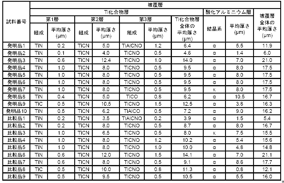
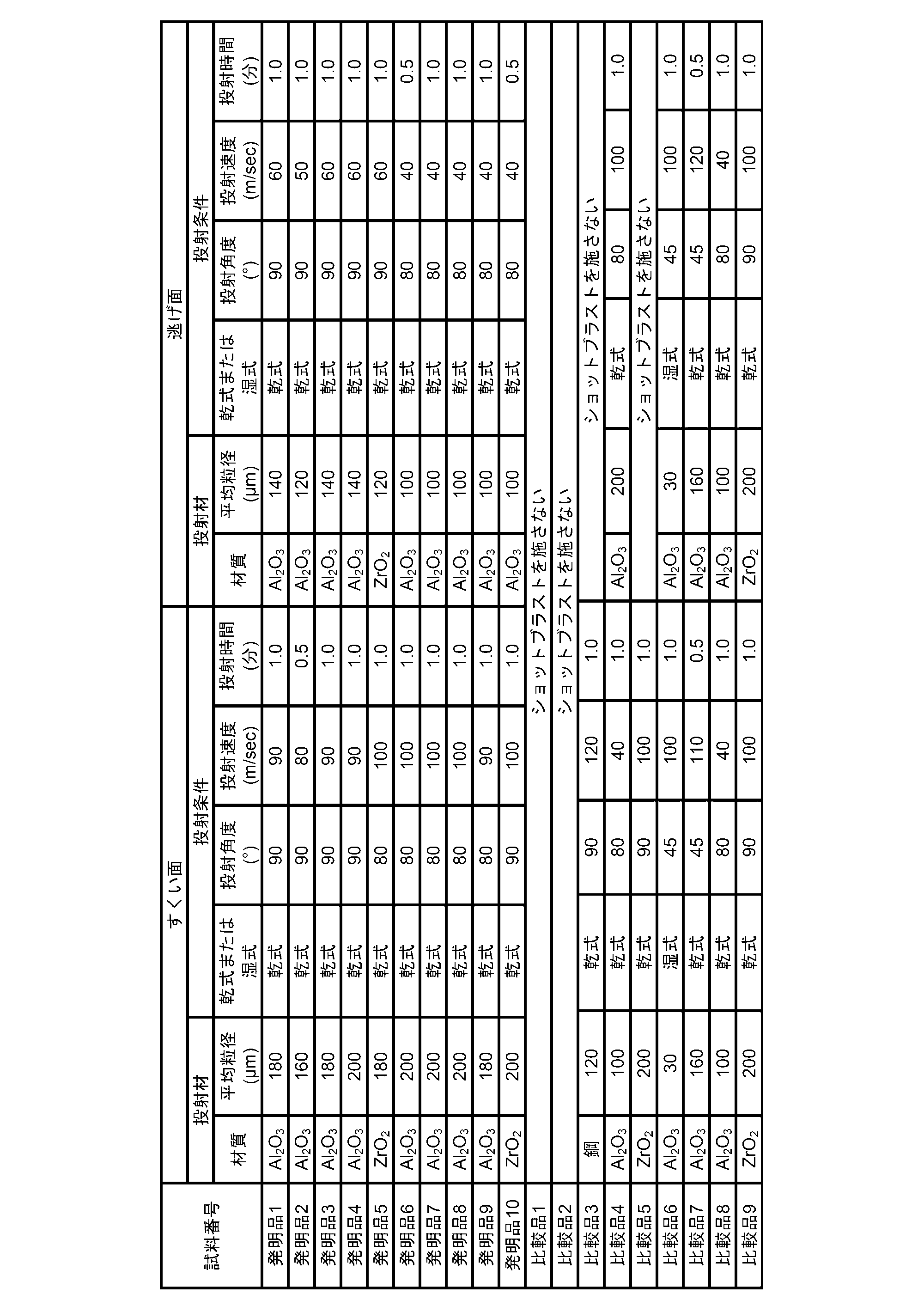
得られた試料の各層の厚さは、被覆切削工具の刃先からすくい面の中心部に向かって50μmの位置の近傍の断面をSEMで3箇所測定し、その平均値(相加平均値)を求めた。
Ti化合物層の領域および断続クラックを測定するため、得られた試料を基材の表面と略平行な方向にTi化合物層が露出するまで研磨した。このとき、すくい面および逃げ面の研磨面をそれぞれ作製した。Ti化合物層の研磨面は、Ti化合物層の平均厚さの70%の厚さが残るような位置となるように調整し、Ti化合物層の研磨面をフッ硝酸にてエッチングした。そのTi化合物層の研磨面を、光学顕微鏡を用いて300倍で観察し、0.33mm2の範囲の研磨面の写真を撮影した。各試料について、3個のインサートを用意し、それぞれ研磨面の写真を用いて、Ti化合物層の領域の個数および断続クラックの個数を求め、それらの値からTi化合物層の領域の平均数密度Aおよび断続クラックの平均数密度Bを求めた。すくい面における、平均数密度をArとし、断続クラックの平均数密度をBrとした。逃げ面における、平均数密度をAfとし、断続クラックの平均数密度をBfとした。それらの結果を表5に示す。

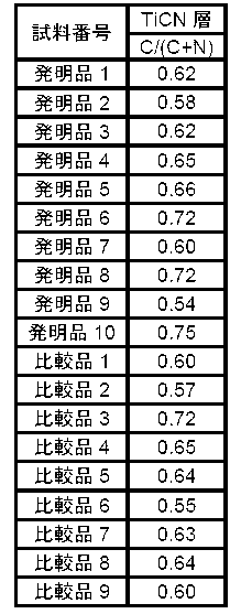
得られた試料のTiCN層に含まれるCとNの合計に対するCの原子比[C/(C+N)]については、被覆切削工具の刃先からすくい面の中心部に向かって50μmの位置の近傍の断面からEPMAを用いて測定した。得られた結果を表6に示す。
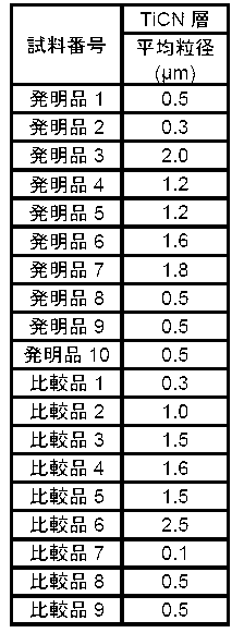
得られた試料を真空中にて1200℃で10分間保持して加熱処理し、TiCN層の結晶粒界に超硬合金基材の結合相の成分を拡散させたのち、被覆切削工具の垂直断面の鏡面研磨面をSEMで観察し、写真を撮影した。撮影したTiCN層の写真の中央部分で超硬合金の基材と被覆層との界面に対して、平行な方向に直線を引き、この直線上を横切るTiCN層の粒界の数を測定して、TiCN層の平均粒径を算出した。このとき、TiCN層の平均厚さの50%の位置に直線を引いた。得られた結果を表7に示す。
得られた試料を用いて、以下の切削試験を行い、評価した。その結果を表8に示す。
[切削試験1:耐摩耗性試験]
被削材:S45Cの丸棒、
切削速度:260m/min、
送り:0.30mm/rev、
切り込み:2.0mm、
クーラント:有り、
評価項目:試料が欠損(表中、「欠損」と記載。)または欠損およびチッピングが生じることなく最大逃げ面摩耗幅が0.2mmに至ったとき(表中、「正常摩耗」と記載。)を工具寿命とし、工具寿命までの加工時間を測定した。
被削材:S45Cの丸棒、
切削速度:260m/min、
送り:0.30mm/rev、
切り込み:2.0mm、
クーラント:有り、
評価項目:試料が欠損(表中、「欠損」と記載。)または欠損およびチッピングが生じることなく最大逃げ面摩耗幅が0.2mmに至ったとき(表中、「正常摩耗」と記載。)を工具寿命とし、工具寿命までの加工時間を測定した。
[切削試験2:耐欠損性試験]
被削材:S45Cの長さ方向に等間隔で2本の溝入り丸棒、
切削速度:220m/min、
送り:0.35mm/rev、
切り込み:1.5mm、
クーラント:有り、
評価項目:試料が欠損に至ったときを工具寿命とし、工具寿命までの衝撃回数を測定した。衝撃回数は、試料と被削材とが接触した回数とし、接触回数が最大で20000回に到達した時点で試験を終了した。なお、各試料について、5個のインサートを用意し、それぞれ衝撃回数を測定し、それらの衝撃回数の値から平均値(相加平均値)を求め、工具寿命とした。
被削材:S45Cの長さ方向に等間隔で2本の溝入り丸棒、
切削速度:220m/min、
送り:0.35mm/rev、
切り込み:1.5mm、
クーラント:有り、
評価項目:試料が欠損に至ったときを工具寿命とし、工具寿命までの衝撃回数を測定した。衝撃回数は、試料と被削材とが接触した回数とし、接触回数が最大で20000回に到達した時点で試験を終了した。なお、各試料について、5個のインサートを用意し、それぞれ衝撃回数を測定し、それらの衝撃回数の値から平均値(相加平均値)を求め、工具寿命とした。
なお、耐摩耗性試験の工具寿命に至るまでの加工時間について、35分以上をA、25分以上35分未満をB、25分未満をCとして評価した。また、耐欠損性試験の工具寿命に至るまでの衝撃回数について、20000回をA、10000回以上20000回未満をB、10000回未満をCとして評価した。この評価では、(優)A>B>C(劣)という順位になり、AまたはBを有するほど切削性能が優れる。

表8の結果より、発明品の耐摩耗性試験および耐欠損性試験の評価は、どちらもB以上の評価であった。一方、比較品は、耐摩耗性試験および耐欠損性試験のいずれかの試験において、評価が、Cであった。また、比較品5および比較品9の耐欠損性試験の評価は、Aであったが、耐摩耗性試験の評価がCであった。よって、発明品は、耐チッピング性および耐欠損性を低下させずに耐摩耗性を向上させたことが分かる。
以上の結果より、耐チッピング性および耐欠損性を低下させずに耐摩耗性を向上させたことにより、発明品の工具寿命が長くなっていることが分かる。
本出願は、2016年5月24日出願の日本特許出願(特願2016-103027)に基づくものであり、その内容はここに参照として取り込まれる。
本発明の被覆切削工具は、耐チッピング性および耐欠損性を損なうことなく、耐摩耗性を向上させることができ、従来よりも工具寿命を延長できるので、そのような要求がある分野において、産業上の利用可能性が高い。
1…基材、2…被覆層、3…すくい面、4…逃げ面、5…切刃稜線部、11…Ti化合物層、12…酸化アルミニウム層、20,30…領域、21~23…小単位、31,32…小さい領域、100…被覆切削工具。
Claims (8)
- 基材と、前記基材の表面に形成された被覆層とを備える被覆切削工具であって、
前記被覆切削工具は、すくい面と、逃げ面と、すくい面と逃げ面との間に切刃稜線部とを有し、
前記被覆層が、少なくとも1層のTi化合物層を含み、
前記Ti化合物層が、TiまたはTiおよびAlと、C、N、OおよびBから成る群より選ばれる少なくとも1種の元素とを含む化合物層であり、
前記Ti化合物層における、前記基材の表面と略平行な研磨面を上面から見たとき、前記Ti化合物層はクラックによって囲まれた領域を有し、
前記領域の内側に、前記領域を囲む前記クラックと、一端または両端で接しない断続クラックを有し、
前記すくい面の少なくとも一部において、前記領域の平均数密度Arと前記断続クラックの平均数密度Brとが0.7<Br/Ar<4.0を満たし、
前記逃げ面の少なくとも一部において、前記領域の平均数密度Afと前記断続クラックの平均数密度Bfとが0.1<Bf/Af<1.5を満たし、
かつ、Br/Ar>Bf/Afである、被覆切削工具。 - 前記すくい面の少なくとも一部において、前記領域の平均数密度Arと前記断続クラックの平均数密度Brとが1.2<Br/Ar<3.0を満たし、
前記逃げ面の少なくとも一部において、前記領域の平均数密度Afと前記断続クラックの平均数密度Bfとが0.1<Bf/Af<1.2を満たす、請求項1に記載の被覆切削工具。 - 前記Ti化合物層が、前記基材の表面に形成され、平均厚さが2.0μm以上20.0μm以下である、請求項1または2に記載の被覆切削工具。
- 前記Ti化合物層が、少なくとも1層のTiCN層を含み、
前記TiCN層の平均粒径は、0.3μm以上2.0μm以下である、請求項1~3のいずれか1項に記載の被覆切削工具。 - 前記TiCN層に含まれる炭素と窒素との合計に対する炭素の原子比[C/(C+N)]が0.50以上0.75以下である、請求項4に記載の被覆切削工具。
- 前記被覆層が、前記Ti化合物層の表面に、平均厚さが1.0μm以上15.0μm以下の酸化アルミニウム層を有する、請求項1~5のいずれか1項に記載の被覆切削工具。
- 前記被覆層の全体の平均厚さが3.0μm以上30.0μm以下である、請求項1~6のいずれか1項に記載の被覆切削工具。
- 前記基材が、超硬合金、サーメット、セラミックスまたは立方晶窒化硼素焼結体のいずれかである、請求項1~7のいずれか1項に記載の被覆切削工具。
Priority Applications (1)
| Application Number | Priority Date | Filing Date | Title |
|---|---|---|---|
| JP2018519525A JP6736032B2 (ja) | 2016-05-24 | 2017-05-22 | 被覆切削工具 |
Applications Claiming Priority (2)
| Application Number | Priority Date | Filing Date | Title |
|---|---|---|---|
| JP2016103027 | 2016-05-24 | ||
| JP2016-103027 | 2016-05-24 |
Publications (1)
| Publication Number | Publication Date |
|---|---|
| WO2017204141A1 true WO2017204141A1 (ja) | 2017-11-30 |
Family
ID=60412318
Family Applications (1)
| Application Number | Title | Priority Date | Filing Date |
|---|---|---|---|
| PCT/JP2017/018987 Ceased WO2017204141A1 (ja) | 2016-05-24 | 2017-05-22 | 被覆切削工具 |
Country Status (2)
| Country | Link |
|---|---|
| JP (1) | JP6736032B2 (ja) |
| WO (1) | WO2017204141A1 (ja) |
Cited By (10)
| Publication number | Priority date | Publication date | Assignee | Title |
|---|---|---|---|---|
| WO2020050260A1 (ja) * | 2018-09-05 | 2020-03-12 | 京セラ株式会社 | 被覆工具及び切削工具 |
| CN113853265A (zh) * | 2019-08-06 | 2021-12-28 | 住友电工硬质合金株式会社 | 切削工具 |
| CN114888975A (zh) * | 2022-05-06 | 2022-08-12 | 东岳机械股份有限公司 | 一种加气混凝土板材刀组自动旋转换刀装置 |
| US11964328B2 (en) | 2018-09-05 | 2024-04-23 | Kyocera Corporation | Coated tool and cutting tool |
| JP7473069B1 (ja) | 2023-12-13 | 2024-04-23 | 株式会社タンガロイ | 被覆切削工具 |
| US11992883B2 (en) | 2018-09-05 | 2024-05-28 | Kyocera Corporation | Coated tool and cutting tool |
| US11998991B2 (en) | 2018-09-05 | 2024-06-04 | Kyocera Corporation | Coated tool and cutting tool |
| US12030127B2 (en) | 2018-09-05 | 2024-07-09 | Kyocera Corporation | Coated tool and cutting tool |
| US12115586B2 (en) | 2018-09-05 | 2024-10-15 | Kyocera Corporation | Coated tool and cutting tool |
| WO2025192090A1 (ja) * | 2024-03-13 | 2025-09-18 | 京セラ株式会社 | 被覆工具及び切削工具 |
Citations (8)
| Publication number | Priority date | Publication date | Assignee | Title |
|---|---|---|---|---|
| US5123934A (en) * | 1989-09-04 | 1992-06-23 | Nippon Steel Corporation | Ceramics coated cemented-carbide tool with high-fracture resistance |
| JP2004216488A (ja) * | 2003-01-14 | 2004-08-05 | Kyocera Corp | 表面被覆切削工具 |
| JP2005205547A (ja) * | 2004-01-23 | 2005-08-04 | Mitsubishi Materials Corp | 硬質被覆層が高速断続切削ですぐれた耐チッピング性を発揮する表面被覆サーメット製切削工具 |
| WO2006011396A1 (ja) * | 2004-07-29 | 2006-02-02 | Kyocera Corporation | 表面被覆切削工具 |
| WO2009041893A1 (en) * | 2007-09-26 | 2009-04-02 | Sandvik Intellectual Property Ab | Cutting tool for chip forming machining of metals |
| WO2015025903A1 (ja) * | 2013-08-21 | 2015-02-26 | 株式会社タンガロイ | 被覆切削工具 |
| JP2015188995A (ja) * | 2014-03-28 | 2015-11-02 | 三菱マテリアル株式会社 | 耐異常損傷性に優れた表面被覆切削工具 |
| JP2016107377A (ja) * | 2014-12-08 | 2016-06-20 | 三菱マテリアル株式会社 | 表面被覆切削工具 |
-
2017
- 2017-05-22 WO PCT/JP2017/018987 patent/WO2017204141A1/ja not_active Ceased
- 2017-05-22 JP JP2018519525A patent/JP6736032B2/ja active Active
Patent Citations (8)
| Publication number | Priority date | Publication date | Assignee | Title |
|---|---|---|---|---|
| US5123934A (en) * | 1989-09-04 | 1992-06-23 | Nippon Steel Corporation | Ceramics coated cemented-carbide tool with high-fracture resistance |
| JP2004216488A (ja) * | 2003-01-14 | 2004-08-05 | Kyocera Corp | 表面被覆切削工具 |
| JP2005205547A (ja) * | 2004-01-23 | 2005-08-04 | Mitsubishi Materials Corp | 硬質被覆層が高速断続切削ですぐれた耐チッピング性を発揮する表面被覆サーメット製切削工具 |
| WO2006011396A1 (ja) * | 2004-07-29 | 2006-02-02 | Kyocera Corporation | 表面被覆切削工具 |
| WO2009041893A1 (en) * | 2007-09-26 | 2009-04-02 | Sandvik Intellectual Property Ab | Cutting tool for chip forming machining of metals |
| WO2015025903A1 (ja) * | 2013-08-21 | 2015-02-26 | 株式会社タンガロイ | 被覆切削工具 |
| JP2015188995A (ja) * | 2014-03-28 | 2015-11-02 | 三菱マテリアル株式会社 | 耐異常損傷性に優れた表面被覆切削工具 |
| JP2016107377A (ja) * | 2014-12-08 | 2016-06-20 | 三菱マテリアル株式会社 | 表面被覆切削工具 |
Cited By (18)
| Publication number | Priority date | Publication date | Assignee | Title |
|---|---|---|---|---|
| US11998991B2 (en) | 2018-09-05 | 2024-06-04 | Kyocera Corporation | Coated tool and cutting tool |
| US12023742B2 (en) | 2018-09-05 | 2024-07-02 | Kyocera Corporation | Coated tool and cutting tool |
| JPWO2020050260A1 (ja) * | 2018-09-05 | 2021-08-30 | 京セラ株式会社 | 被覆工具及び切削工具 |
| US12115586B2 (en) | 2018-09-05 | 2024-10-15 | Kyocera Corporation | Coated tool and cutting tool |
| US12030127B2 (en) | 2018-09-05 | 2024-07-09 | Kyocera Corporation | Coated tool and cutting tool |
| JP7133629B2 (ja) | 2018-09-05 | 2022-09-08 | 京セラ株式会社 | 被覆工具及び切削工具 |
| CN112654450B (zh) * | 2018-09-05 | 2024-02-23 | 京瓷株式会社 | 涂层刀具及切削刀具 |
| US11964328B2 (en) | 2018-09-05 | 2024-04-23 | Kyocera Corporation | Coated tool and cutting tool |
| CN112654450A (zh) * | 2018-09-05 | 2021-04-13 | 京瓷株式会社 | 涂层刀具及切削刀具 |
| WO2020050260A1 (ja) * | 2018-09-05 | 2020-03-12 | 京セラ株式会社 | 被覆工具及び切削工具 |
| US11992883B2 (en) | 2018-09-05 | 2024-05-28 | Kyocera Corporation | Coated tool and cutting tool |
| CN113853265B (zh) * | 2019-08-06 | 2024-03-01 | 住友电工硬质合金株式会社 | 切削工具 |
| CN113853265A (zh) * | 2019-08-06 | 2021-12-28 | 住友电工硬质合金株式会社 | 切削工具 |
| CN114888975B (zh) * | 2022-05-06 | 2024-05-10 | 东岳机械股份有限公司 | 一种加气混凝土板材刀组自动旋转换刀装置 |
| CN114888975A (zh) * | 2022-05-06 | 2022-08-12 | 东岳机械股份有限公司 | 一种加气混凝土板材刀组自动旋转换刀装置 |
| JP7473069B1 (ja) | 2023-12-13 | 2024-04-23 | 株式会社タンガロイ | 被覆切削工具 |
| JP2025094660A (ja) * | 2023-12-13 | 2025-06-25 | 株式会社タンガロイ | 被覆切削工具 |
| WO2025192090A1 (ja) * | 2024-03-13 | 2025-09-18 | 京セラ株式会社 | 被覆工具及び切削工具 |
Also Published As
| Publication number | Publication date |
|---|---|
| JP6736032B2 (ja) | 2020-08-05 |
| JPWO2017204141A1 (ja) | 2019-03-28 |
Similar Documents
| Publication | Publication Date | Title |
|---|---|---|
| WO2017204141A1 (ja) | 被覆切削工具 | |
| KR101722009B1 (ko) | 피복 절삭 공구 | |
| JP6521127B2 (ja) | 被覆切削工具 | |
| KR101843453B1 (ko) | 피복절삭공구 | |
| JP6973026B2 (ja) | 被覆切削工具 | |
| CN110023011B (zh) | 被覆切削工具 | |
| WO2015068792A1 (ja) | 被覆切削工具 | |
| JP6727553B2 (ja) | 被覆切削工具 | |
| JP6708261B2 (ja) | 被覆切削工具 | |
| WO2013042790A1 (ja) | 被覆切削工具 | |
| CN109475945B (zh) | 被覆切削工具 | |
| JP6210347B1 (ja) | 被覆切削工具 | |
| JP6296058B2 (ja) | 被覆切削工具 | |
| JP7137141B2 (ja) | 被覆切削工具 | |
| JP7137143B2 (ja) | 被覆切削工具 | |
| JP2019107720A (ja) | 被覆切削工具 |
Legal Events
| Date | Code | Title | Description |
|---|---|---|---|
| ENP | Entry into the national phase |
Ref document number: 2018519525 Country of ref document: JP Kind code of ref document: A |
|
| NENP | Non-entry into the national phase |
Ref country code: DE |
|
| 121 | Ep: the epo has been informed by wipo that ep was designated in this application |
Ref document number: 17802733 Country of ref document: EP Kind code of ref document: A1 |
|
| 122 | Ep: pct application non-entry in european phase |
Ref document number: 17802733 Country of ref document: EP Kind code of ref document: A1 |