WO2017203875A1 - 画像診断装置、及び画像取得方法 - Google Patents
画像診断装置、及び画像取得方法 Download PDFInfo
- Publication number
- WO2017203875A1 WO2017203875A1 PCT/JP2017/014966 JP2017014966W WO2017203875A1 WO 2017203875 A1 WO2017203875 A1 WO 2017203875A1 JP 2017014966 W JP2017014966 W JP 2017014966W WO 2017203875 A1 WO2017203875 A1 WO 2017203875A1
- Authority
- WO
- WIPO (PCT)
- Prior art keywords
- correction
- image
- unit
- noise reduction
- observation data
- Prior art date
- Legal status (The legal status is an assumption and is not a legal conclusion. Google has not performed a legal analysis and makes no representation as to the accuracy of the status listed.)
- Ceased
Links
Images


Classifications
-
- G—PHYSICS
- G01—MEASURING; TESTING
- G01R—MEASURING ELECTRIC VARIABLES; MEASURING MAGNETIC VARIABLES
- G01R33/00—Arrangements or instruments for measuring magnetic variables
- G01R33/20—Arrangements or instruments for measuring magnetic variables involving magnetic resonance
- G01R33/44—Arrangements or instruments for measuring magnetic variables involving magnetic resonance using nuclear magnetic resonance [NMR]
- G01R33/48—NMR imaging systems
- G01R33/54—Signal processing systems, e.g. using pulse sequences ; Generation or control of pulse sequences; Operator console
- G01R33/56—Image enhancement or correction, e.g. subtraction or averaging techniques, e.g. improvement of signal-to-noise ratio and resolution
- G01R33/5608—Data processing and visualization specially adapted for MR, e.g. for feature analysis and pattern recognition on the basis of measured MR data, segmentation of measured MR data, edge contour detection on the basis of measured MR data, for enhancing measured MR data in terms of signal-to-noise ratio by means of noise filtering or apodization, for enhancing measured MR data in terms of resolution by means for deblurring, windowing, zero filling, or generation of gray-scaled images, colour-coded images or images displaying vectors instead of pixels
-
- A—HUMAN NECESSITIES
- A61—MEDICAL OR VETERINARY SCIENCE; HYGIENE
- A61B—DIAGNOSIS; SURGERY; IDENTIFICATION
- A61B5/00—Measuring for diagnostic purposes; Identification of persons
- A61B5/05—Detecting, measuring or recording for diagnosis by means of electric currents or magnetic fields; Measuring using microwaves or radio waves
- A61B5/055—Detecting, measuring or recording for diagnosis by means of electric currents or magnetic fields; Measuring using microwaves or radio waves involving electronic [EMR] or nuclear [NMR] magnetic resonance, e.g. magnetic resonance imaging
-
- A—HUMAN NECESSITIES
- A61—MEDICAL OR VETERINARY SCIENCE; HYGIENE
- A61B—DIAGNOSIS; SURGERY; IDENTIFICATION
- A61B6/00—Apparatus or devices for radiation diagnosis; Apparatus or devices for radiation diagnosis combined with radiation therapy equipment
- A61B6/02—Arrangements for diagnosis sequentially in different planes; Stereoscopic radiation diagnosis
- A61B6/03—Computed tomography [CT]
- A61B6/032—Transmission computed tomography [CT]
-
- A—HUMAN NECESSITIES
- A61—MEDICAL OR VETERINARY SCIENCE; HYGIENE
- A61B—DIAGNOSIS; SURGERY; IDENTIFICATION
- A61B6/00—Apparatus or devices for radiation diagnosis; Apparatus or devices for radiation diagnosis combined with radiation therapy equipment
- A61B6/52—Devices using data or image processing specially adapted for radiation diagnosis
- A61B6/5205—Devices using data or image processing specially adapted for radiation diagnosis involving processing of raw data to produce diagnostic data
-
- A—HUMAN NECESSITIES
- A61—MEDICAL OR VETERINARY SCIENCE; HYGIENE
- A61B—DIAGNOSIS; SURGERY; IDENTIFICATION
- A61B6/00—Apparatus or devices for radiation diagnosis; Apparatus or devices for radiation diagnosis combined with radiation therapy equipment
- A61B6/52—Devices using data or image processing specially adapted for radiation diagnosis
- A61B6/5258—Devices using data or image processing specially adapted for radiation diagnosis involving detection or reduction of artifacts or noise
-
- A—HUMAN NECESSITIES
- A61—MEDICAL OR VETERINARY SCIENCE; HYGIENE
- A61B—DIAGNOSIS; SURGERY; IDENTIFICATION
- A61B8/00—Diagnosis using ultrasonic, sonic or infrasonic waves
- A61B8/52—Devices using data or image processing specially adapted for diagnosis using ultrasonic, sonic or infrasonic waves
- A61B8/5207—Devices using data or image processing specially adapted for diagnosis using ultrasonic, sonic or infrasonic waves involving processing of raw data to produce diagnostic data, e.g. for generating an image
-
- A—HUMAN NECESSITIES
- A61—MEDICAL OR VETERINARY SCIENCE; HYGIENE
- A61B—DIAGNOSIS; SURGERY; IDENTIFICATION
- A61B8/00—Diagnosis using ultrasonic, sonic or infrasonic waves
- A61B8/52—Devices using data or image processing specially adapted for diagnosis using ultrasonic, sonic or infrasonic waves
- A61B8/5269—Devices using data or image processing specially adapted for diagnosis using ultrasonic, sonic or infrasonic waves involving detection or reduction of artifacts
-
- G—PHYSICS
- G01—MEASURING; TESTING
- G01R—MEASURING ELECTRIC VARIABLES; MEASURING MAGNETIC VARIABLES
- G01R33/00—Arrangements or instruments for measuring magnetic variables
- G01R33/20—Arrangements or instruments for measuring magnetic variables involving magnetic resonance
- G01R33/44—Arrangements or instruments for measuring magnetic variables involving magnetic resonance using nuclear magnetic resonance [NMR]
- G01R33/48—NMR imaging systems
- G01R33/54—Signal processing systems, e.g. using pulse sequences ; Generation or control of pulse sequences; Operator console
- G01R33/56—Image enhancement or correction, e.g. subtraction or averaging techniques, e.g. improvement of signal-to-noise ratio and resolution
- G01R33/565—Correction of image distortions, e.g. due to magnetic field inhomogeneities
- G01R33/56509—Correction of image distortions, e.g. due to magnetic field inhomogeneities due to motion, displacement or flow, e.g. gradient moment nulling
-
- G—PHYSICS
- G06—COMPUTING OR CALCULATING; COUNTING
- G06T—IMAGE DATA PROCESSING OR GENERATION, IN GENERAL
- G06T5/00—Image enhancement or restoration
- G06T5/70—Denoising; Smoothing
-
- G—PHYSICS
- G06—COMPUTING OR CALCULATING; COUNTING
- G06T—IMAGE DATA PROCESSING OR GENERATION, IN GENERAL
- G06T5/00—Image enhancement or restoration
- G06T5/73—Deblurring; Sharpening
-
- G—PHYSICS
- G01—MEASURING; TESTING
- G01R—MEASURING ELECTRIC VARIABLES; MEASURING MAGNETIC VARIABLES
- G01R33/00—Arrangements or instruments for measuring magnetic variables
- G01R33/20—Arrangements or instruments for measuring magnetic variables involving magnetic resonance
- G01R33/44—Arrangements or instruments for measuring magnetic variables involving magnetic resonance using nuclear magnetic resonance [NMR]
- G01R33/48—NMR imaging systems
- G01R33/54—Signal processing systems, e.g. using pulse sequences ; Generation or control of pulse sequences; Operator console
- G01R33/546—Interface between the MR system and the user, e.g. for controlling the operation of the MR system or for the design of pulse sequences
-
- G—PHYSICS
- G06—COMPUTING OR CALCULATING; COUNTING
- G06T—IMAGE DATA PROCESSING OR GENERATION, IN GENERAL
- G06T2207/00—Indexing scheme for image analysis or image enhancement
- G06T2207/10—Image acquisition modality
- G06T2207/10072—Tomographic images
- G06T2207/10088—Magnetic resonance imaging [MRI]
Definitions
- the present invention relates to an image diagnostic apparatus, and relates to a high image quality technology in image processing.
- Magnetic Resonance Imaging which is one of the medical diagnostic imaging systems, is a method that uses nuclear magnetic resonance (Nuclear Magnetic Resonance: NMR) phenomenon to image information on a subject such as a living body. .
- NMR nuclear magnetic resonance
- the MRI system has a principle that the signal-to-noise ratio (SNR) decreases when the resolution is increased.
- SNR signal-to-noise ratio
- the SNR is improved by increasing the number of signal additions (Number of EXcitations: NEX) in which the same part, that is, the same position is imaged and added a plurality of times.
- Patent Document 1 discloses image correction processing using Retinex theory using visual characteristics.
- An object of the present invention is to solve the above-described problems and provide an image diagnostic apparatus and an image acquisition method capable of maintaining image quality and reducing processing time with an MRI image with a small number of additions.
- a diagnostic imaging apparatus for reducing noise in observation data converted into an image, and for reducing noise obtained from the noise reduction unit by humans.
- An image diagnostic apparatus having a configuration including an image correction unit that performs a correction process using the visual characteristics of the image.
- an image diagnostic apparatus includes a noise reduction unit that reduces noise of observation data converted into an image, and noise reduction data obtained by the noise reduction unit.
- a separation unit that separates a global luminance component from a local variation component, an observation data, noise reduction data, a correction degree calculation unit that calculates a correction degree using the global luminance component, an observation data, a local variation component, and
- An image diagnostic apparatus comprising: a correction processing unit that performs correction using a correction degree; and a correction control unit that controls a noise reduction unit, a correction degree calculation unit, and a correction processing unit using parameters at the time of observation data acquisition I will provide a.
- an image acquisition method for an image diagnostic apparatus including noise reduction processing for reducing noise from acquired observation data, and noise reduction obtained by the noise reduction processing. Separation processing that separates the global luminance component and local fluctuation component from the data, correction degree calculation processing that calculates the correction degree using the observation data, noise reduction data, and the global luminance component, observation data, local data
- an image acquisition method for performing correction processing using a fluctuation component and a correction degree is provided.
- the present invention it is possible to acquire a high-quality image while shortening the photographing time in the diagnostic imaging apparatus.
- Example 3 is a diagram illustrating an example of a configuration of an image processing unit in Embodiment 1.
- FIG. It is a figure which shows an example of the processing flow of the noise reduction process in Example 1.
- FIG. 3 is a diagram illustrating an example of a configuration of an image correction unit in Embodiment 1.
- FIG. 6 is a diagram for explaining a correction degree map creation method according to the first embodiment. 6 is a diagram illustrating an example of presentation of an input unit according to Embodiment 1.
- FIG. 6 is a diagram illustrating a display example of a display unit in Embodiment 1.
- FIG. 6 is a diagram illustrating an example of a configuration of an image processing unit in Embodiment 2.
- FIG. 6 is a block diagram illustrating an example of the overall configuration of an ultrasonic diagnostic apparatus according to a third embodiment.
- FIG. 10 is a block diagram illustrating an example of an overall configuration of a CT apparatus according to a fourth embodiment.
- Example 1 includes a noise reduction unit that reduces noise in observation data converted into an image, an image correction unit that performs correction processing using human visual characteristics on noise reduction data obtained by the noise reduction unit, and Image diagnostic apparatus having a configuration including the above, and an image acquisition method of the image diagnostic apparatus, wherein noise reduction processing for reducing noise from acquired observation data and noise reduction data obtained by the noise reduction processing Separation process that separates luminance component and local fluctuation component, correction degree calculation process that calculates correction degree using observation data, noise reduction data, and global luminance component, observation data, local fluctuation component, and correction It is an Example of the image acquisition method which performs a correction process using a degree.
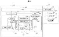
- FIG. 1 is a diagram illustrating an example of the overall configuration of the MRI apparatus according to the first embodiment.
- the MRI apparatus which is a medical image diagnostic apparatus, is roughly divided into an observation unit 100 that observes a subject and outputs observation data, and a reconstructor that reconstructs an image of the subject based on the observation data. Consists of a configuration unit 106.
- the observation unit 100 includes a static magnetic field generation system 102, a gradient magnetic field generation system 103, a transmission system 104, a reception system 105, a sequencer 107, and a central processing unit (CPU) 108.
- the static magnetic field generation system 102 generates a uniform magnetic field in the space around the subject 101.
- the static magnetic field generation system 102 is provided with a permanent magnet or a normal or superconducting magnetic field generating means.
- the gradient magnetic field generation system 103 includes a gradient magnetic field coil 109 and a gradient magnetic field power source 110 that drives the gradient magnetic field coil 109, and applies a gradient magnetic field to the subject 101.
- the sequencer 107 is a control unit that repeatedly applies a high-frequency magnetic field pulse (RF pulse) and a gradient magnetic field pulse in a predetermined pulse sequence.
- the sequencer 107 operates under the control of the CPU 108 and performs various processes necessary for collecting tomographic image data of the subject 101. Is transmitted to the transmission system 104, the gradient magnetic field generation system 103, and the reception system 105.
- the transmission system 104 includes a high-frequency generator 111, a modulator 112, an amplifier 113, and a high-frequency coil 114a, and irradiates an RF pulse that causes nuclear magnetic resonance on the atomic nuclear spins of the subject 101.
- the reception system 105 includes a high-frequency coil 114b, an amplifier 115, a quadrature detector 116, and an analog / digital (A / D) converter 117, receives an echo signal emitted by nuclear magnetic resonance of nuclear spins, and receives observation data. Is transmitted to the reconstruction unit 106.
- the reconstruction unit 106 includes an image processing unit 118, an input unit 119 including a keyboard, mouse, touch panel, buttons, etc., an output unit 120 including a display, a printer, etc., a magnetic disk, an optical disk, etc.
- the storage device 121 stores a program.
- the image processing unit 118 reconstructs an image, causes the output unit 120 to display it, and records it in the storage device 121.
- the image processing unit 118 can be realized by program processing by the CPU 108, but a central processing unit (CPU) different from the CPU 108 is installed and used in the reconstruction unit 106. It is also possible to configure and process with dedicated hardware for image processing.
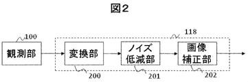
- FIG. 2 is a functional block diagram illustrating an example of processing performed by the image processing unit 118 in the MRI apparatus of the present embodiment.
- the image processing unit 118 according to the present embodiment includes a conversion unit 200 that converts observation data observed by the observation unit 100 into an image by Fourier transform, a noise reduction unit 201 that reduces noise in the observation data converted into an image,
- the image correction unit 202 performs correction processing using human visual characteristics.
- the correction processing using human visual characteristics is correction processing using, for example, Retinex theory, and includes edge enhancement, contrast change, and the like. Correction processing using human visual characteristics will be described later.
- the noise reduction unit 201 reduces noise in the image obtained by converting the observation data.
- Noise reduction processing includes techniques such as a weighted smoothing filter, bilateral filter, non-local mean filter, and guided filter.
- a noise reduction process using the sparsity of an image will be described.
- the sparsity of the image that is, the sparseness, indicates a property in which many zero components are included in an image or a coefficient converted by an arbitrary basis function.
- FIG. 3 is a diagram illustrating an example of processing of the noise reduction unit 201 of the present embodiment. As shown in FIG. 3, the noise reduction unit 201 performs initialization in step ST300 and then repeatedly executes steps ST301 to ST305, thereby reducing noise included in observation data converted into an image.
- step ST301 equation (1) is calculated, and an estimation result u k + 1 is calculated.
- f k represents the frequency component of the image updated by the previous (k-th) iteration
- ⁇ represents the Fourier transform
- ⁇ T represents the inverse transform of ⁇
- I N is an array having all elements of 1 and the same size as f k .
- U C k , u w k , b C k , and b w k are change components calculated in the immediately preceding (k-th) iteration.
- ⁇ is a positive constant as a parameter.
- step ST402 u C k + 1 and u w k + 1 are calculated by equations (2) and (3).
- ⁇ c T and ⁇ w T are a Curvelet inverse transform and a Wavelet inverse transform, respectively.
- Curvelet transform and Wavelet transform are used, but TV (Total Variation), Ridgelet transform, etc. may be used in addition to this. Moreover, you may use combining these.
- S C and S w represents a process called Soft - shrinkage.
- Each expression for S C and S w are all elements (4), the processing shown by (5).
- ⁇ c and ⁇ w are Curvelet transform and Wavelet transform, respectively.
- ⁇ is a constant as a parameter.
- step ST303 b C k + 1 and b w k + 1 are calculated using equations (6) and (7).
- an end determination is made in step ST304.
- the end is determined when the maximum value, total value, etc. of the change components u and b are less than the specified value, or when the number of repetitions reaches a certain number.
- the image correction unit 202 performs correction processing using human visual characteristics, that is, corrects an MRI image based on human visual characteristics.
- correction processing using human visual characteristics is, for example, Retinex that has color constancy and brightness constancy that human eyes can feel color and brightness regardless of illumination light.
- FIG. 4 is a diagram illustrating an example of processing of the image correction unit 202 of the present embodiment.
- the image correction unit 202 is calculated by a separation unit 400 that separates a global luminance component and a local variation component, a correction degree calculation unit 401 that calculates a correction degree at each position of the input image, and
- the image correction unit 402 is configured to correct an image using each component and the degree of correction.
- I (x, y) is a noise reduced image input from the noise reduction unit 201
- G (x, y) is a blur function
- * is a convolution operation.
- a moving average filter a Gaussian filter, a bilateral filter, etc.
- a convolution process may be used as a product-sum operation using Fourier transform.
- the correction degree calculation unit 401 calculates the correction degree at each position of the input image and creates a correction degree map C.
- any one or a combination of luminance, gradient, difference value between the input image and the noise-reduced image, MRI imaging parameters, or the like can be used as an evaluation index.
- the correction degree calculation unit 401 creates a correction degree map for each evaluation index used for calculating the correction degree.
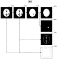
- FIG. 5 is a schematic diagram for explaining an outline of the correction degree map C created by the correction degree calculation unit 401.
- the noise reduction image 501 calculated by the noise reduction unit 201 based on the observation image 500 obtained by converting the observation data by the conversion unit 200 of the image processing unit 118 is input to the separation unit 400 of the image correction unit 202.
- the separation unit 400 separates the global luminance component and the local variation component into a global luminance component 502.
- the degree-of-correction calculation unit 401 to which the global luminance component 502 is input for example, to suppress the noise in the low luminance region, the correction degree is 0 or higher for the region below the predetermined threshold in the global luminance component 502
- a correction degree map 503 is created with the luminance as an evaluation index with a correction degree of 1.
- the brightness range correction degree map 504 is calculated by setting the brightness range such as th1 to th2.
- the correction degree is binary (0 (black) or 1 (white)), but any value may be used.
- the gradient correction degree map 505 is calculated by calculating the gradient by, for example, a difference method, a Sobel filter, etc., and setting a large correction degree in an area having a large gradient. Further, as the evaluation index, a difference value between the input observation image 500 and the noise reduction image 501 can be calculated, and the correction degree map 506 can be calculated by estimating the area reduced as noise. As described above, the correction degree calculation unit 401 according to the present embodiment calculates one or n correction degree maps 503 to 506. By calculating a plurality of correction degree maps, it is possible to control the area for contrast correction and edge enhancement and the strength of each correction effect. That is, in the apparatus of the present embodiment, the correction degree calculation unit 401 can perform a more flexible correction process by calculating a plurality of correction degrees based on a plurality of evaluation indexes.
- the correction processing unit 402 corrects the noise-reduced image by Expression (10) using the local variation component R separated by the separation unit 400 and the correction degree map C calculated by the correction degree calculation unit 401.
- O (x, y) is a corrected image corrected by the correction degree calculation unit 401
- C i (x, y) is a calculated correction degree map
- ⁇ is a positive parameter that controls the correction ratio.
- the final correction degree at each pixel position is calculated by Equation (10), and the input image is corrected.
- the correction degree map is multiplied here, it may be substituted by addition.
- the correction degree is standardized in the range of 0 to 1, the final correction degree falls within the range of 0 to 1 by using multiplication, so that correction can be performed more easily.
- the correction degree can be calculated more flexibly by using a configuration in which addition or a polynomial in which addition and multiplication are combined. That is, in the correction processing unit 402 of the present embodiment, a flexible response can be made by performing a correction process by multiplying or adding a plurality of correction degrees calculated by the correction degree calculating unit 401 or combining the addition and multiplication. Can do.
- the image correction unit 202 corrects using observation data converted into an image by the conversion unit, noise reduction data output from the noise reduction unit, and a general luminance component in the noise reduction data.
- the correction degree calculation unit that calculates the degree of correction, the local fluctuation component in the observation data, the noise reduction data, and the correction processing unit that performs correction using the correction degree enables more flexible calculation of the correction degree. is there.
- the input unit 119 of the reconstruction unit 106 is used to allow the user to set parameters for noise reduction processing and correction processing.
- FIG. 6 shows an example of a screen presented to the user in the input unit 119. As shown in FIG. 6, numerical input 600, radio button input 601, slider input 602, and the like are conceivable. At this time, it is desirable to prepare several parameter sets. Further, the user may be able to select for each imaging region or imaging mode of the subject.
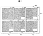
- the output unit 120 includes an output device such as a display, and displays an observation image, a noise reduction image, and a correction image obtained by each functional block shown in FIG.
- FIG. 7 is a display example on an output device such as a display of the output unit 120.
- a combination of correction degree maps and a plurality of correction results 704 to 706 with different correction processes are simultaneously displayed on the output device 700. It may be possible that the user can select.
- an area 707 for displaying the type of correction map, parameters, and the like used for processing may be displayed.
- the configuration of the present embodiment it is possible to capture high-quality MRI images that can withstand clinical use at high speed by correction processing using human visual characteristics, and by shortening the imaging time based on the reduction in the number of additions It is possible to reduce the patient burden and improve the diagnosis efficiency.
- Example 2 is an example in which a user can easily obtain a preferable image by controlling noise removal and correction using various parameters of an MRI apparatus.
- the present embodiment is an image diagnosis apparatus, which includes a noise reduction unit that reduces noise of observation data converted into an image, and a global luminance component and local variation from the noise reduction data obtained by the noise reduction unit.
- a separation unit that separates components, a correction degree calculation unit that calculates a correction degree using observation data, noise reduction data, and a global luminance component, and correction using the observation data, local variation component, and correction degree
- Example of image diagnostic apparatus and image acquisition method configured to include correction processing unit to perform, and noise reduction unit, correction degree calculation unit, and correction control unit for controlling correction processing unit using parameters at the time of observation data acquisition It is.
- the overall configuration of the MRI apparatus is represented in FIG.
- This embodiment differs from the first embodiment in that the observation parameter of the observation unit 100 is used in the noise reduction unit 201 and the image correction unit 202 for performing correction processing using human visual characteristics.
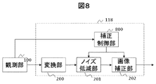
- FIG. 8 is a block diagram showing an example of a main part configuration in the second embodiment.
- a correction control unit 700 that controls the noise reduction unit 201 and the image correction unit 202 is added to the image processing unit 118.
- the correction control unit 800 receives parameter information used during observation from the observation unit 100.
- the parameter information used at the time of observation includes, for example, TR (Repetition Time), flip angle, slice thickness, FOV (Field of View), matrix size, the number of additions of signals to be captured and added, bandwidth, It is site
- TR Reference Time
- FOV Field of View
- matrix size the number of additions of signals to be captured and added
- bandwidth It is site
- the SNR varies depending on these parameters, the user can easily obtain a more suitable image by performing appropriate noise reduction and correction using these parameters. For example, when the number of additions is small, the SNR is expected to decrease, so it is necessary to increase the noise reduction effect and the correction effect.
- the correction control unit 800 calculates appropriate noise reduction and correction parameters from the above parameters, and transmits them to the noise reduction unit 201 and the image correction unit 202, respectively.
- the parameters transmitted to the noise reduction unit 201 are the parameter ⁇ used in Equation (1) and the parameter ⁇ used in Equations (4) and (5).
- SNR decreases when TR is short, flip angle is small, slice pressure is thin, FOV is small, matrix size is large, number of additions is small, bandwidth is wide It is. In practice, it is desirable to determine the final correction parameters using these combinations.
- a correction parameter table for these parameters may be prepared and stored in the storage unit of the CPU 108 or the storage device 121 of the reconstruction unit 106 for use. When a decrease in SNR is expected, the correction controller 800 can improve the noise reduction effect by increasing the parameter ⁇ and the parameter ⁇ .
- a correction degree map calculation parameter for example, a threshold value, a luminance width, correction degree information about each, and the like are transmitted. That is, more appropriate correction is performed by defining in advance a clinically necessary luminance range using mode information and part information in MRI imaging and calculating a defined correction parameter. For example, in the MRI image, when the luminance of the observation target is approximately in the range of th1 to th2, th1 and th2 are transmitted to the correction degree calculation unit 401, and a correction degree map is created. Examples of the correction degree map to be created include a brightness range correction degree map using th1 and th2, and a gradient correction degree map using gradients near th1 and th2.
- the correction processing parameter is the parameter ⁇ used in Equation (10).
- the correction processing parameter ⁇ is transmitted to the correction processing unit 402 of the image correction unit 202.
- the correction control unit 800 increases the correction processing parameter ⁇ so that the correction is executed more strongly and a suitable image can be acquired.
- the user can easily obtain a suitable MRI image by using various parameters of the MRI apparatus.
- Example 3 is an example in which the image diagnostic apparatus is an ultrasonic diagnostic apparatus.
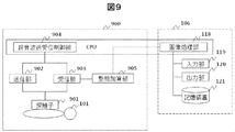
- FIG. 9 is a block diagram illustrating a configuration example of an ultrasonic diagnostic apparatus that is a medical image diagnostic apparatus.
- an ultrasonic observation unit 900 constituting an ultrasonic diagnostic apparatus includes an ultrasonic probe 901, a transmission unit 902, a reception unit 903, an ultrasonic transmission / reception control unit 904, and a phasing addition unit 905. Composed.
- the transmission unit 902 repeatedly transmits ultrasonic waves to the subject 101 via the ultrasonic probe 901 at time intervals.
- the receiving unit 903 receives a time-series reflected echo signal generated from the subject 101.
- the ultrasonic transmission / reception control unit 904 controls the transmission unit 902 and the reception unit 903.
- the phasing addition unit 905 phasing-adds the received reflected echo signals to generate RF signal frame data in time series.
- the phasing / adding unit 905 includes an analog / digital (A / D) converter, and outputs RF signal frame data as observation data to the image processing unit 118 of the reconstruction unit 106.
- the image processing unit 118 converts the RF frame data from the RF frame data. An ultrasonic echo image is generated using the observed data.
- the ultrasonic observation unit 900 transmits observation data to the image processing unit 118.
- the image processing unit 118 in this embodiment is also represented in FIG.
- the conversion unit 200 of the image processing unit 118 converts the RF frame data into an image. Correction processing using the human visual characteristics shown in the first or second embodiment is performed on the converted image, and a high-quality ultrasonic image can be calculated.
- the ultrasonic diagnostic apparatus of this embodiment it is possible to acquire a high-quality ultrasonic image.
- Example 4 is an example of a CT apparatus in which the diagnostic imaging apparatus can acquire a high-quality CT (Computed Tomography) image.
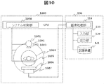
- FIG. 10 is a block diagram showing a configuration example of a CT (Computed Tomography) apparatus as a medical image diagnostic apparatus. Also in the figure, the same components as those shown in FIG. 1 are denoted by the same reference numerals, and the description thereof is omitted.
- the CT observation unit 1000 includes an X-ray tube device 1001, a rotating disk 1002, a collimator 1003, an X-ray detector 1006, a data collection device 1007, a bed 1005, and a system control unit 1008.
- the X-ray tube apparatus 1001 is an apparatus that irradiates a subject placed on a bed 1005 with X-rays.
- the collimator 1003 is a device that limits the radiation range of X-rays emitted from the X-ray tube device 1001.
- the rotating disk 1002 includes an opening 1004 into which a subject placed on a bed 1005 enters, and an X-ray tube device 1001 and an X-ray detector 1006 are mounted to rotate around the subject.
- the X-ray detector 1006 is a device that measures the spatial distribution of transmitted X-rays by detecting X-rays that are arranged opposite to the X-ray tube device 1001 and transmitted through the subject.
- the rotating disk 1002 is arranged in the rotating direction, or the rotating disk 1002 is arranged two-dimensionally in the rotating direction and the rotating shaft direction.
- the data collection device 1007 is a device that collects the X-ray dose detected by the X-ray detector 1006 as digital data.
- the system control unit 1008 controls the rotation of the rotating disk 1002, the up / down / left / right movement of the bed 1005, the electric power input to the X-ray tube apparatus 1001, and the like.
- the CT observation unit 1000 of the CT apparatus of the present embodiment transmits observation data to the image processing unit 118 of the reconstruction unit 106.
- the image processing unit 118 in this embodiment is also represented in FIG.
- the conversion unit 200 converts the observation data into an image by processing such as a filter-corrected back projection method and a successive approximation image reconstruction method.
- the converted image is subjected to correction processing using the human visual characteristics shown in the first or second embodiment, and a high-quality CT image is calculated.
- a high-quality CT image can be acquired. Furthermore, the X-ray dose can be reduced as compared with the conventional case, and a reduction in exposure dose can be expected.
- this invention is not limited to the above-mentioned Example, Various modifications are included.
- the above-described embodiments have been described in detail for better understanding of the present invention, and are not necessarily limited to those having all the configurations described.
- a part of the configuration of one embodiment can be replaced with the configuration of another embodiment, and the configuration of another embodiment can be added to the configuration of one embodiment.
- observation section 101 Subject 102 Static magnetic field generation system 103 Gradient magnetic field generation system 104 Transmission system 105 Reception system 106 Reconstruction part 107 Sequencer 108 Central processing unit (CPU) 109 gradient coil 110 Gradient magnetic field power supply 111 high frequency generator 112 modulator 113, 115 Amplifier 114 high frequency coil 116 Quadrature detector 117 Analog-to-digital (A / D) converter 118 Image processing section 119 Input section 120 Output section 121 Storage device 200 Converter 201 Noise reduction part 202 Image correction unit 400 Separator 401 Correction degree calculator 402 Correction processing section 500 observation images 501 Noise reduction image 502 Global luminance component 503-505 Correction degree map 600 Numeric input 601 Input with radio buttons 602 Input by slider 700 display units 701 Observation image 702 Noise reduction image 703 Corrected image 704 to 706 Noise reduced or corrected image 707 display area 800 Correction control unit 900 Ultrasonic observation section 901 transducer 902 Transmitter 903 Receiver 904 Ultrasonic wave transmission / reception controller
Landscapes
- Health & Medical Sciences (AREA)
- Engineering & Computer Science (AREA)
- Life Sciences & Earth Sciences (AREA)
- Physics & Mathematics (AREA)
- Nuclear Medicine, Radiotherapy & Molecular Imaging (AREA)
- Medical Informatics (AREA)
- General Health & Medical Sciences (AREA)
- Radiology & Medical Imaging (AREA)
- High Energy & Nuclear Physics (AREA)
- Public Health (AREA)
- Animal Behavior & Ethology (AREA)
- Veterinary Medicine (AREA)
- Surgery (AREA)
- Biophysics (AREA)
- Pathology (AREA)
- Biomedical Technology (AREA)
- Heart & Thoracic Surgery (AREA)
- Molecular Biology (AREA)
- Computer Vision & Pattern Recognition (AREA)
- General Physics & Mathematics (AREA)
- Optics & Photonics (AREA)
- Signal Processing (AREA)
- Condensed Matter Physics & Semiconductors (AREA)
- Theoretical Computer Science (AREA)
- Artificial Intelligence (AREA)
- Pulmonology (AREA)
- Image Processing (AREA)
- Magnetic Resonance Imaging Apparatus (AREA)
- Apparatus For Radiation Diagnosis (AREA)
- Ultra Sonic Daignosis Equipment (AREA)
- Image Analysis (AREA)
Priority Applications (2)
| Application Number | Priority Date | Filing Date | Title |
|---|---|---|---|
| US16/093,680 US10732245B2 (en) | 2016-05-26 | 2017-04-12 | Diagnostic imaging device and image acquisition method |
| CN201780031293.1A CN109152549B (zh) | 2016-05-26 | 2017-04-12 | 图像诊断装置以及图像取得方法 |
Applications Claiming Priority (2)
| Application Number | Priority Date | Filing Date | Title |
|---|---|---|---|
| JP2016-105023 | 2016-05-26 | ||
| JP2016105023A JP6744764B2 (ja) | 2016-05-26 | 2016-05-26 | 画像診断装置、及び画像取得方法 |
Publications (1)
| Publication Number | Publication Date |
|---|---|
| WO2017203875A1 true WO2017203875A1 (ja) | 2017-11-30 |
Family
ID=60412333
Family Applications (1)
| Application Number | Title | Priority Date | Filing Date |
|---|---|---|---|
| PCT/JP2017/014966 Ceased WO2017203875A1 (ja) | 2016-05-26 | 2017-04-12 | 画像診断装置、及び画像取得方法 |
Country Status (4)
| Country | Link |
|---|---|
| US (1) | US10732245B2 (enExample) |
| JP (1) | JP6744764B2 (enExample) |
| CN (1) | CN109152549B (enExample) |
| WO (1) | WO2017203875A1 (enExample) |
Cited By (1)
| Publication number | Priority date | Publication date | Assignee | Title |
|---|---|---|---|---|
| WO2020031362A1 (ja) * | 2018-08-10 | 2020-02-13 | 三菱電機株式会社 | 画像処理装置及び画像処理方法 |
Families Citing this family (8)
| Publication number | Priority date | Publication date | Assignee | Title |
|---|---|---|---|---|
| JP7186604B2 (ja) * | 2018-12-25 | 2022-12-09 | キヤノンメディカルシステムズ株式会社 | 医用画像処理装置、医用画像処理方法、およびプログラム |
| JP7455508B2 (ja) | 2018-12-26 | 2024-03-26 | キヤノンメディカルシステムズ株式会社 | 磁気共鳴イメージング装置および医用複素数画像処理装置 |
| JP7297485B2 (ja) * | 2019-03-25 | 2023-06-26 | キヤノンメディカルシステムズ株式会社 | 超音波診断装置、医用画像処理装置および医用画像処理プログラム |
| DE102019217220A1 (de) * | 2019-11-07 | 2021-05-12 | Siemens Healthcare Gmbh | Computerimplementiertes Verfahren zur Bereitstellung eines Ausgangsdatensatzes |
| JP7529892B2 (ja) * | 2020-07-31 | 2024-08-06 | マックス-プランク-ゲゼルシャフト ツール フェルデルンク デル ヴィッセンシャフテン エー.ファウ. | ボリュームを網羅する拡散強調磁気共鳴画像のシーケンスを取得し再構成する方法及び装置 |
| JP7473507B2 (ja) | 2021-06-11 | 2024-04-23 | 富士フイルムヘルスケア株式会社 | 超音波診断装置及び画像処理方法 |
| CN113469919B (zh) * | 2021-07-27 | 2024-05-28 | 深圳市赛禾医疗技术有限公司 | 超声图像的处理方法、装置及电子设备 |
| JP2024114385A (ja) * | 2023-02-13 | 2024-08-23 | 富士フイルムヘルスケア株式会社 | 画像処理装置及びそれを有するmri装置、及び画像処理方法 |
Citations (2)
| Publication number | Priority date | Publication date | Assignee | Title |
|---|---|---|---|---|
| JP2005004506A (ja) * | 2003-06-12 | 2005-01-06 | Minolta Co Ltd | 画像処理プログラム |
| JP2013183834A (ja) * | 2012-03-07 | 2013-09-19 | Hitachi Consumer Electronics Co Ltd | 医療用画像表示システム |
Family Cites Families (5)
| Publication number | Priority date | Publication date | Assignee | Title |
|---|---|---|---|---|
| DE10351928A1 (de) * | 2003-11-07 | 2005-06-16 | MAX-PLANCK-Gesellschaft zur Förderung der Wissenschaften e.V. | Messung am visuellen System eines Probanden |
| US9008749B2 (en) * | 2010-02-08 | 2015-04-14 | Koninklijke Philips N.V. | Apparatus and method for influencing and/or detecting magnetic particles in a field of view having an array of single-sided transmit coil sets |
| US8787638B2 (en) * | 2011-04-07 | 2014-07-22 | The Chinese University Of Hong Kong | Method and device for retinal image analysis |
| JP6071444B2 (ja) * | 2012-11-07 | 2017-02-01 | キヤノン株式会社 | 画像処理装置及びその作動方法、プログラム |
| CN105125176B (zh) * | 2015-09-23 | 2018-07-10 | 博联众科(武汉)科技有限公司 | 一种静脉血管导航装置和方法 |
-
2016
- 2016-05-26 JP JP2016105023A patent/JP6744764B2/ja active Active
-
2017
- 2017-04-12 US US16/093,680 patent/US10732245B2/en active Active
- 2017-04-12 WO PCT/JP2017/014966 patent/WO2017203875A1/ja not_active Ceased
- 2017-04-12 CN CN201780031293.1A patent/CN109152549B/zh active Active
Patent Citations (2)
| Publication number | Priority date | Publication date | Assignee | Title |
|---|---|---|---|---|
| JP2005004506A (ja) * | 2003-06-12 | 2005-01-06 | Minolta Co Ltd | 画像処理プログラム |
| JP2013183834A (ja) * | 2012-03-07 | 2013-09-19 | Hitachi Consumer Electronics Co Ltd | 医療用画像表示システム |
Non-Patent Citations (4)
| Title |
|---|
| HONGQING HU , GUOQIANG NI: "Magetic Resonance Image Enhancement based on Multiscale Retinex Algorithm", 2010 3RD INTERNATIONAL CONFERENCE ON BIOMEDICAL ENGINEERING AND INFORMATICS, vol. 1, 2010, pages 345 - 348, XP031804033 * |
| KATSUMI TSUJIOKA: "60. Chikuji Kinji Gazo Filter to shite no TV-ho", INNERVISION, vol. 28, no. 5, 2013, pages 122 - 123 * |
| NARUOMI YASUDA ET AL.: "Understanding of retinex theory and its application to medical x-ray images", GIFU UNIVERSITY OF MEDICAL SCIENCE KIYO, no. 9, 2015, pages 59 - 65 * |
| ZOHAIR AL-AMEEN ET AL.: "A New Algorithm for Improving the Low Contrast of Computed Tomography Images Using Tuned Brightness Controlled Single-Scale Retinex", SCANNING, vol. 37, no. 2, 6 February 2015 (2015-02-06), pages 116 - 125, XP055600677 * |
Cited By (2)
| Publication number | Priority date | Publication date | Assignee | Title |
|---|---|---|---|---|
| WO2020031362A1 (ja) * | 2018-08-10 | 2020-02-13 | 三菱電機株式会社 | 画像処理装置及び画像処理方法 |
| JPWO2020031362A1 (ja) * | 2018-08-10 | 2021-01-07 | 三菱電機株式会社 | 画像処理装置及び画像処理方法 |
Also Published As
| Publication number | Publication date |
|---|---|
| JP2017209329A (ja) | 2017-11-30 |
| CN109152549A (zh) | 2019-01-04 |
| US20190137589A1 (en) | 2019-05-09 |
| CN109152549B (zh) | 2022-08-02 |
| US10732245B2 (en) | 2020-08-04 |
| JP6744764B2 (ja) | 2020-08-19 |
Similar Documents
| Publication | Publication Date | Title |
|---|---|---|
| JP6744764B2 (ja) | 画像診断装置、及び画像取得方法 | |
| KR101604812B1 (ko) | 의료 영상 처리 장치 및 그에 따른 의료 영상 처리 방법 | |
| JP6855223B2 (ja) | 医用画像処理装置、x線コンピュータ断層撮像装置及び医用画像処理方法 | |
| JP4820582B2 (ja) | ヘリカルマルチスライスctのための回復ノイズを伴うヘリカルウィンドミルアーチファクトを低減する方法 | |
| US11419555B2 (en) | Image capturing apparatus and method | |
| CN103366388B (zh) | 用于双模态ct数据的迭代的图像重建的方法 | |
| WO2005046478A1 (ja) | 画像処理方法、画像処理装置、医用画像診断支援システム、及び時間軸方向フィルタリング方法 | |
| US10885680B2 (en) | Medical imaging device, image processing method, and program | |
| KR20170088681A (ko) | 단층 촬영 장치 및 그에 따른 단층 영상 복원 방법 | |
| KR101665513B1 (ko) | 컴퓨터 단층 촬영 장치 및 그에 따른 ct 영상 복원 방법 | |
| US8503755B2 (en) | Tomosynthesis method with an iterative maximum a posteriori reconstruction | |
| EP3349655B1 (en) | Tomography apparatus and controlling method for the same | |
| KR20160120963A (ko) | 단층 촬영 장치 및 그에 따른 단층 영상 복원 방법 | |
| KR20170030308A (ko) | 단층 촬영 장치 및 그에 따른 단층 영상 복원 방법 | |
| US12458301B2 (en) | X-ray CT apparatus and high-quality image generation device | |
| US20230342995A1 (en) | Patch-based medical image generation for complex input datasets | |
| US12271441B2 (en) | Medical data processing apparatus and method | |
| JP6377712B2 (ja) | 超音波診断装置、及び画像撮像方法 | |
| JP7317655B2 (ja) | 医用画像処理装置および医用画像処理方法 | |
| Malczewski et al. | Semi-propeller compressed sensing MR image super-resolution reconstruction |
Legal Events
| Date | Code | Title | Description |
|---|---|---|---|
| NENP | Non-entry into the national phase |
Ref country code: DE |
|
| 121 | Ep: the epo has been informed by wipo that ep was designated in this application |
Ref document number: 17802474 Country of ref document: EP Kind code of ref document: A1 |
|
| 122 | Ep: pct application non-entry in european phase |
Ref document number: 17802474 Country of ref document: EP Kind code of ref document: A1 |