WO2017203644A1 - 情報処理装置、情報処理装置の支持装置、及び情報処理装置の支持装置の制御プログラム - Google Patents
情報処理装置、情報処理装置の支持装置、及び情報処理装置の支持装置の制御プログラム Download PDFInfo
- Publication number
- WO2017203644A1 WO2017203644A1 PCT/JP2016/065508 JP2016065508W WO2017203644A1 WO 2017203644 A1 WO2017203644 A1 WO 2017203644A1 JP 2016065508 W JP2016065508 W JP 2016065508W WO 2017203644 A1 WO2017203644 A1 WO 2017203644A1
- Authority
- WO
- WIPO (PCT)
- Prior art keywords
- information processing
- processing apparatus
- command
- support device
- shooting
- Prior art date
- Legal status (The legal status is an assumption and is not a legal conclusion. Google has not performed a legal analysis and makes no representation as to the accuracy of the status listed.)
- Ceased
Links
Images











Classifications
-
- G—PHYSICS
- G03—PHOTOGRAPHY; CINEMATOGRAPHY; ANALOGOUS TECHNIQUES USING WAVES OTHER THAN OPTICAL WAVES; ELECTROGRAPHY; HOLOGRAPHY
- G03B—APPARATUS OR ARRANGEMENTS FOR TAKING PHOTOGRAPHS OR FOR PROJECTING OR VIEWING THEM; APPARATUS OR ARRANGEMENTS EMPLOYING ANALOGOUS TECHNIQUES USING WAVES OTHER THAN OPTICAL WAVES; ACCESSORIES THEREFOR
- G03B15/00—Special procedures for taking photographs; Apparatus therefor
-
- G—PHYSICS
- G03—PHOTOGRAPHY; CINEMATOGRAPHY; ANALOGOUS TECHNIQUES USING WAVES OTHER THAN OPTICAL WAVES; ELECTROGRAPHY; HOLOGRAPHY
- G03B—APPARATUS OR ARRANGEMENTS FOR TAKING PHOTOGRAPHS OR FOR PROJECTING OR VIEWING THEM; APPARATUS OR ARRANGEMENTS EMPLOYING ANALOGOUS TECHNIQUES USING WAVES OTHER THAN OPTICAL WAVES; ACCESSORIES THEREFOR
- G03B17/00—Details of cameras or camera bodies; Accessories therefor
- G03B17/56—Accessories
-
- H—ELECTRICITY
- H04—ELECTRIC COMMUNICATION TECHNIQUE
- H04N—PICTORIAL COMMUNICATION, e.g. TELEVISION
- H04N5/00—Details of television systems
- H04N5/222—Studio circuitry; Studio devices; Studio equipment
Definitions
- the present invention relates to an information processing device, a support device for the information processing device, and a control program for the support device for the information processing device.
- Patent Document 1 describes as a problem that “When an image is taken by an electronic camera, the distance to the subject (self) can only be the length of his / her arm. "It is difficult to take a picture of the scenery + yourself”, and the solution is "The gripping unit with the operation unit required for shooting is configured separately from the imaging device itself, Rotation / extension is possible with the faces facing each other in parallel, and a switch is provided to detect the rotation, so that the image display unit switches from the back to the front of the imaging device. It is disclosed that the photographer who wants to monitor can easily monitor (summary excerpt).
- Patent Document 1 it is necessary to manually adjust the length of the selfie stick in order to adjust the distance between the information processing terminal and the subject to the angle of view.
- the information processing terminal may come into contact with a peripheral object, such as a person or an object, and adjustment may be necessary again. is there.
- a peripheral object such as a person or an object
- This invention solves the said subject, and aims at providing the technique which improves the operativity at the time of adjusting the length of the support apparatus of information processing apparatus.
- the present invention includes a plurality of means for solving the above problems.
- the information processing apparatus includes an imaging unit and a support device including a rod-shaped main body that expands and contracts.
- a support device control unit that generates a decompression command to extend or a shortening command to shorten the main body based on a captured image captured by the imaging unit, and a command for the support device generated by the support device control unit, And a communication unit for transmitting to the support device.
- FIG. 9 is a flowchart showing a flow of panoramic shooting processing for imaging a plurality of people. It is a block diagram which shows the internal structure of the information processing apparatus concerning 3rd embodiment. It is a software block diagram which shows the internal structure of the information processing apparatus concerning 3rd embodiment. It is a flowchart explaining the operation example of the selfie stick control execution program in connection with 3rd embodiment.
- an information processing apparatus having an imaging unit and an image pickup communication-connected to a self-shooting stick control device built in a self-taking stick supporting the information processing apparatus (corresponding to a support device of the information processing apparatus)
- the present invention relates to a system, a selfie stick control method using the system, and an information processing device and a selfie stick included in the imaging system.
- FIG. 1A is a block diagram illustrating an example of an internal configuration of the information processing apparatus 100 according to the present embodiment.
- an information processing apparatus 100 includes a CPU (Central Processing Unit) 101, a system bus 102, a ROM (Read Only Memory) 103, a RAM (Random Access Memory) 104, a storage 110, a communication processor 120, an expansion interface 125, It comprises an operating device 130, a video processor 140, an audio processor 150, and a sensor 160.
- a CPU Central Processing Unit
- ROM Read Only Memory
- RAM Random Access Memory
- the CPU 101 is a microprocessor unit that controls the entire information processing apparatus 100.
- a system bus 102 is a data communication path for performing data transmission / reception between the CPU 101 and each operation block in the information processing apparatus 100.
- the ROM 103 is a memory in which a basic operation program such as an operating system and other operation programs are stored. For example, a rewritable ROM such as an EEPROM (Electrically Erasable and Programmable Read Only Memory) or a flash ROM is used.
- the RAM 104 serves as a work area when the basic operation program and other operation programs are executed.
- the ROM 103 and the RAM 104 may be integrated with the CPU 101. Further, the ROM 103 may not use an independent configuration as shown in FIG. 1A but may use a partial storage area in the storage 110.
- the storage 110 stores an operation program and an operation setting value of the information processing apparatus 100, an image captured by the information processing apparatus 100, information on a user of the information processing apparatus 100, and the like.
- All or part of the functions of the ROM 103 may be replaced by a partial area of the storage 110.
- the storage 110 needs to hold stored information even when power is not supplied to the information processing apparatus 100 from the outside. Therefore, for example, devices such as a flash ROM, SSD (Solid State Drive), HDD (Hard Disk Drive) are used.
- each operation program stored in the ROM 103 or the storage 110 can be updated and expanded by a download process from each server device (not shown) on the wide area public network.
- the communication processor 120 includes a LAN (Local Area Network) communication device 121, a telephone network communication device 122, an NFC (Near Field Communication) communication device 123, and a Bluetooth (registered trademark) communication device 124.
- the LAN communication device 121 is connected to a wide area public network via an access point (AP) device (not shown) by wireless connection such as Wi-Fi (registered trademark), and transmits / receives data to / from each server device on the wide area public network. I do.
- the telephone network communicator 122 performs telephone communication (call) and data transmission / reception by wireless communication with a base station (not shown) of the mobile telephone communication network.
- the NFC communicator 123 performs wireless communication when close to the corresponding reader / writer.
- the Bluetooth communication device 124 transmits and receives data by wireless communication with a corresponding terminal.
- the LAN communication device 121, the telephone network communication device 122, the NFC communication device 123, and the Bluetooth communication device 124 each include a coding circuit, a decoding circuit, an antenna, and the like.
- the communication processor 120 may further include infrared communication or other communication devices.
- the extended interface 125 is an interface group for extending the functions of the information processing apparatus 100.
- the extended interface 125 includes a video / audio interface, a USB (Universal Serial Bus) interface, a memory interface, and the like.
- the video / audio interface performs input of video signals / audio signals from external video / audio output devices, output of video signals / audio signals to external video / audio input devices, and the like.
- the USB interface is connected to a PC (Personal Computer) or the like to transmit / receive data. A keyboard or other USB device may be connected.
- the memory interface transmits and receives data by connecting a memory card and other memory media.
- the operation device 130 is an instruction input device that inputs an operation instruction to the information processing apparatus 100.
- the operation device 130 includes an operation key in which a touch panel and button switches arranged on the display 141 are arranged. . Only one of them may be used, or the information processing apparatus 100 may be operated using a keyboard or the like connected to the expansion interface 125. Further, the information processing apparatus 100 may be operated using a separate mobile terminal device connected by wired communication or wireless communication.
- the touch panel function may be provided in the display 141.
- the video processor 140 includes a display 141, an image signal processor 142, a camera A 143 (corresponding to a photographing unit used to control expansion / contraction of the self-shooting stick), and a camera B 144.
- the camera A 143 is a camera arranged on the same surface (front surface) as the display 141, and is used for so-called self-photographing, for example, by checking and photographing the face captured by the camera A 143 with the display 141.
- the camera B 144 is a camera arranged on the opposite side (back side) of the display 141.
- the display 141 is a display device such as a liquid crystal panel, for example, and displays the image data processed by the image signal processor 142 and provides it to the user of the information processing apparatus 100.
- the image signal processor 142 includes a video RAM (not shown), and the display 141 is driven based on image data input to the video RAM. Further, the image signal processor 142 has a function of performing format conversion, menu and other OSD (On-Screen Display) signal superimposing processing as required.
- the camera A 143 and the camera B 144 convert the light input from the lens into an electrical signal using an electronic device such as a CCD (Charge-Coupled Device) or a CMOS (Complementary Metal Metal Oxide Semiconductor) sensor. It is a camera unit that functions as an imaging device for inputting data.
- CCD Charge-Coupled Device
- CMOS Complementary Metal Metal Oxide Semiconductor
- the audio processor 150 includes a speaker 151, an audio signal processor 152, and a microphone 153.
- the speaker 151 provides the audio signal processed by the audio signal processor 152 to the user of the information processing apparatus 100.
- the microphone 153 converts the user's voice and the like into voice data and inputs the voice data.
- the sensor 160 is a sensor group for detecting the state of the information processing apparatus 100.
- the GPS (Global Positioning System) receiver 161 the gyro sensor 162, the geomagnetic sensor 163, the acceleration sensor 164, and the illuminance sensor 165 are used.
- the human sensor 166 is included. With these sensor groups, it is possible to detect the position, inclination, direction, movement, ambient brightness, and the like of the information processing apparatus 100.
- the information processing apparatus 100 may further include a pressure sensor or other sensor such as an atmospheric pressure sensor. The location information is acquired by the GPS receiver 161.
- the location information cannot be acquired in a place where GPS radio waves are difficult to enter, it can be acquired from the location information in the Wi-Fi AP device by the LAN communication device 121. Alternatively, it may be acquired from the base station information by the telephone network communicator 122.
- the information processing apparatus 100 may be a mobile phone, a smart phone, a digital still camera, a video camera capable of moving image shooting, or other portable digital devices.
- the configuration example of the information processing apparatus 100 illustrated in FIG. 1A includes many configurations that are not essential to the present embodiment, such as the communication processor 120. There is no loss of form effect. Further, a configuration not shown in the figure such as a digital broadcast receiving function and an electronic money settlement function may be further added.
- FIG. 1B is a software configuration diagram illustrating an example of an internal configuration of the information processing apparatus 100 according to the present embodiment.
- the ROM 103 includes a basic operation program 103a such as an operating system and other operation programs 103b.
- the storage 110 includes a face recognition program 110a (which constitutes a face recognition unit in the execution state of the CPU 101) for recognizing a face portion from an image taken by the camera A 143 or the camera B 144, and control of expansion / contraction and rotation of the selfie stick.
- the self-shooting stick control program 110b for performing and other operation programs 110c are stored.
- the storage 110 is provided with various information / data storage areas 110d, a self-shooting stick control information storage area 110d1 for storing information such as setting values for controlling the self-taking stick, a user name and a user A user information storage area 110d2 for storing face recognition information for recognizing the image, and an image information storage area 110d3 for storing a photographed image.
- the programs stored in the ROM 103 and the storage 110 are a basic operation execution program 104a for executing a basic operation program, a face recognition execution program 104b for recognizing a face portion from an image captured by the camera A 143, and a selfie stick 200, respectively.
- a self-shooting stick control execution program 104c for controlling expansion / contraction and rotation of the image and executed by the CPU 101. This constitutes a support device control unit.
- a part of the RAM 104 is provided with a temporary storage area 104d that temporarily holds data as necessary when each program is executed.
- the selfie stick control information storage area 110 d 1 provided in the storage 110 may be provided in the temporary storage area 104 d of the RAM 104.
- FIG. 2A shows an external view of the selfie stick 200 in the present embodiment.
- the selfie stick 200 is detachably attached to a rod-shaped main body 210, a gripping portion 220 held by one end of the main body 210, and an information processing apparatus 100 provided at the other end of the main body 210. And a device mounting portion 230.
- the main body 210 includes a cylindrical member 211 and a rod-shaped member 212 accommodated therein, and an expansion / contraction mechanism 213 that feeds and accommodates the rod-shaped member 212 from the cylindrical member 211 (for example, a mechanism such as a rack and pinion). And a motor 204 (corresponding to an expansion / contraction driving device) for driving the expansion / contraction mechanism 213.
- the device mounting portion 230 is a first rotating shaft having a distal end portion 231 of the rod-shaped member 212, a projection extending from the distal end portion 231 in a direction orthogonal to the axial direction of the rod-shaped member 212, and a rotation axis orthogonal to the axial direction of the rod-shaped member 212 233, a support portion 232 connected to the tip portion 231 via the first rotation shaft 233, a projection protruding from the support portion 232 in a direction parallel to the axial direction of the rod-shaped member 212, and a rotation parallel to the axial direction of the rod-shaped member 212
- a second rotation shaft 234 having a shaft and a fixing portion 201 that is connected to the support portion 232 via the second rotation shaft 234 and to which the information processing apparatus 100 is detachably attached.
- first rotation shaft 233 is accommodated in the tip portion 231, and a motor 203 (corresponding to the first drive device) that rotates the first rotation shaft 233 is accommodated in the tip portion 231.
- second rotation shaft 234 is accommodated in the support portion 232, and a motor 202 (corresponding to the second drive device) that rotates the second rotation shaft 234 is accommodated in the support portion 232.
- the first rotating shaft 233 rotates the information processing apparatus 100 attached to the fixed unit 201 in the vertical direction (tilt direction).
- the second rotation shaft 234 rotates the information processing apparatus 100 attached to the fixed unit 201 in the left-right direction (pan direction).
- an operation input button 205 On the grip 220, as an operation input button 205, an on / off switch 205a for performing an operation input for starting and ending the expansion of the selfie stick 200, and a shutter button 205b for performing an operation input of a shutter of the camera A 143 to the information processing apparatus 100.
- a power supply unit including a battery or the like (not shown), a drive control device for driving a motor, and the like are included.
- FIG. 2B is a functional block diagram showing a connection relationship between the selfie stick 200 and the information processing apparatus 100.
- the selfie stick 200 includes a selfie stick control device 250 (corresponding to an expansion / contraction drive control device) that outputs a drive control signal to the motors 202, 203, and 204.
- the selfie stick control device 250 includes a CPU 251, a ROM 252, a RAM 253, a communication interface 254 for communication connection with the information processing apparatus 100, each component in the selfie stick 200, such as motors 202, 203, 204, and an on / off switch.
- the information processing apparatus 100 and the selfie stick 200 are communicatively connected via the control line 300 to the expansion interface 125 of the information processing apparatus 100 and the communication interface 254 of the selfie stick 200. Therefore, the expansion interface 125 constitutes a device communication unit.
- the extension interface 125 and the communication interface 254 of the selfie stick 200 are configured according to the type of the control line 300, but the extension interface 125 and the communication interface 254 of the selfie stick 200 (corresponding to the selfie stick communication unit) are It may be configured by a USB interface and may be configured by using a wired control line as the control line 300.
- the self-shooting stick control device 250 may be provided with the Bluetooth communicator 257, and the control signal and the operation signal may be input and output wirelessly with the Bluetooth communicator 124 of the information processing apparatus 100.
- the control line 300 is configured by a wireless network.
- a control signal is output from the information processing apparatus 100 to the selfie stick 200 via the control line 300 to expand, contract, rotate and rotate the selfie stick 200 from the selfie stick 200 to the information processing apparatus 100.
- a shutter operation signal of the camera A 143 of the information processing apparatus 100 by the operation input button 205 is output.
- FIG. 3 starts when the main power of the selfie stick 200 and the information processing apparatus 100 is turned on.
- an image signal is output from the camera A 143 or the camera B 144 to the image signal processor 142, and a through image is displayed on the display 141.
- the through image is displayed on the display 141 until the function of the camera A 143 or the camera B 144 is stopped, the captured still image is displayed, or the main power of the information processing apparatus 100 is turned off.
- which image of the camera A 143 or the camera B 144 is displayed on the display 141 can be determined by the initial setting or the user setting of the information processing apparatus 100.
- the user first sets the shooting conditions (S101).
- An example of shooting condition setting will be described with reference to FIGS.
- FIG. 4 is an example of shooting condition setting, and is an example of shooting condition information stored in the selfie stick control information storage area 110d1. Therefore, the self-shooting stick control information storage area 110d1 corresponds to a shooting condition storage unit.
- the shooting condition information includes the size of the face to be shot (face image prescribed value), vertical shooting position information of the face in the shot image, horizontal shooting position information, and user authentication on / off setting information.
- FIG. 5A is an example of setting the size of the face at the time of shooting, and here, it is assumed that the selection is made from among three levels of setting “Large / Middle / Small”. Here, the size is designated by the size of the face in the vertical direction.
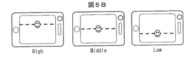
- FIG. 5B is an example of setting the position of the face in the vertical direction at the time of shooting, and here, it is assumed that a selection is made from three settings of “High / Middle / Low”.
- FIG. 5C shows an example of setting the position of the face in the left-right direction at the time of shooting, and here, it is assumed that one of the three settings “Left / Center / Right” is selected.
- the “arbitrary” setting is selected in FIG. 4, the user can arbitrarily set the face size and the face position at the time of shooting using the operation device 130 such as a touch panel arranged so as to overlap the display 141. .
- the process returns to S102 to accept the input. If the input of the on / off switch 205a is present (Yes), a vertical rotation control process is performed (S104).
- the vertical rotation control process S104 as will be described later, based on the image acquired from the camera A 143, the motor 203 is driven so that the position of the user's face in the captured image becomes the set vertical position.
- a branching process is performed depending on whether the difference between the face size recognized in the image acquired from the camera A 143 and the face size set in FIG. 4 is equal to or less than a predetermined value ⁇ s (S105). If the difference between the recognized face size and the set face size is greater than or equal to a predetermined value ⁇ s (No), expansion / contraction determination processing is performed based on the recognized face size and the set face size (S106). ), Branch processing is performed based on the determination result (S107).
- the branch process S107 when the CPU 101 determines that the selfie stick 200 is “extend”, the branch process is performed based on whether or not the length of the selfie stick 200 in the expansion / contraction direction is the longest (S108).
- the branch process S108 when the length of the self-shooting stick 200 in the expansion / contraction direction is not the longest (No), the CPU 101 generates an extension command and outputs it to the self-shooting stick control device 250.
- the selfie stick control device 250 drives and controls the motor 204, and with the rotation of the motor 204, the telescopic mechanism 213 feeds the stick member 212 to the outside of the cylindrical member 211, so that the selfie stick 200 is moved by a predetermined length ⁇ X. Extend (S109).
- ⁇ X is an initial increase / decrease amount of the selfie stick 200 in the expansion / contraction direction.
- ⁇ X is moved to return to S104, and the size of the face image in the subject image is again compared with the set value (S105).
- the so-called feedback control in which the expansion / contraction operation is continued or stopped according to the result will be described as an example.
- the self-shooting stick 200 is expanded and contracted by ⁇ X, so that the self-shooting stick 200 described later is processed in parallel with the process for preventing interference with surrounding people and objects before the face image reaches the set value. Even so, it is easy to stop the expansion and contraction of the self-shooting stick 200.
- self-portrait stick control is performed in advance on the amount-of-expansion information that correlates the difference between the face size recognized in the subject image and the face size set in FIG.
- the information is stored in the information storage area 110d1, and the CPU 101 obtains the amount of expansion / contraction corresponding to the size difference in the expansion / contraction determination process, and outputs a control signal indicating the amount of expansion / contraction to the selfie stick control device 250. Also good.
- accompanying image processing such as face recognition processing is not required during the expansion / contraction operation of the self-portrait stick 200, so that the processing load in the expansion / contraction operation of the self-portrait rod 200 can be reduced.
- the selfie stick 200 can be expanded and contracted at a higher speed.
- An example of the expansion / contraction operation of the selfie stick 200 is not limited to the present embodiment, and a program for performing a plurality of expansion / contraction processes is mounted on one selfie stick 200, and the user performs a safety mode (a mode in which the extension / contraction operation is slowly performed by feedback control). And a high-speed mode (a mode in which the amount of expansion and contraction is calculated to expand and contract the selfie stick 200) may be selected.
- the branching process is performed based on whether the length of the self-shooting stick 200 in the expansion / contraction direction is the shortest (S110).
- the CPU 101 when the length of the self-shooting stick 200 in the expansion / contraction direction is not the shortest (No), the CPU 101 generates a shortening command and outputs it to the self-shooting stick control device 250 to control the selfie stick control.
- the apparatus 250 drives the motor 204, and the expansion / contraction mechanism 213 operates in a direction in which the rod-shaped member 212 is accommodated in the cylindrical member 211, and contracts the selfie stick 200 by a predetermined length ⁇ X (S111). Then, it returns to S104 and performs a vertical rotation control process.
- the process proceeds to the left / right rotation control process S112.
- the motor 202 is driven so that the position of the user's face in the captured image becomes the set left / right position.
- an input is accepted by the operation input button 205 of the selfie stick 200 (S113), and a branch process based on the accepted input is performed (S114). If there is no input in the branch process S114, the process returns to S113 to accept the input.
- the image captured by the camera A 143 is captured (still image capturing) (S115), and the captured image (still image) is stored in the image information storage area 110d3 of the storage 110. Then (S116), the process returns to S113.
- a shortening process for driving the motor 204 so that the self-taking rod 200 is in the shortest state is performed (S117), and the self-taking rod control execution program is terminated.
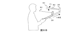
- FIGS. 8A and 8B show the center of the vertical angle of view in the camera A 143 of the information processing apparatus 100 when the selfie stick 200 is extended.
- FIG. 8A shows a case where the vertical rotation control is not performed when the self-portrait stick 200 is extended.
- the center of the vertical angle of view before expansion is the center position 6a1 of the vertical angle of view before expansion, and the center of the vertical angle of view after expansion.
- the position is displaced to the position 6a2, and the vertical position of the user's face is changed.
- FIG. 8B shows a case where the vertical rotation control is performed by ⁇ v when the self-portrait stick 200 is extended, and the vertical angle of view after expansion with respect to the center position 6b1 of the vertical angle of view before expansion. Is 6b3, so that the vertical position of the user's face in the captured image of the camera A143 can be kept unchanged.
- the vertical rotation control process S104 is performed to set the position of the user's face in the captured image to the set vertical position. It becomes possible.
- a through image captured by the camera A 143 is captured (S201), one frame included in the through image acquired by the face recognition execution program 104b is read, and a portion where the face is reflected is recognized. (S202).
- branch processing is performed based on the difference between the vertical center position of the recognized face image and the vertical shooting position setting shown in FIGS. 4 and 5B (S203).
- the branching process S203 if the deviation between the vertical center position of the face image and the set vertical shooting position is larger than the predetermined range ⁇ v (No), the vertical image center position set as the vertical position of the face image is set.
- a vertical rotation determination process is performed from the position (S204), and a branch process is performed based on the determination result (S205).
- step S205 If it is determined in the branch process S205 that the rotation is upward, the CPU 101 outputs an upward rotation command to the selfie stick control device 250 so that the selfie stick control device 250 rotates a predetermined angle ⁇ v upward. Then, the motor 203 is driven (S206), and the process returns to S201 to capture the image taken by the camera A143 again. If it is determined that the rotation is downward, the CPU 101 outputs a downward rotation command to the selfie stick control device 250, and drives the motor 203 so that the selfie stick control device 250 rotates downward by a predetermined angle ⁇ v. In step S207, the process returns to step S201, and the image captured by the camera A 143 is captured again.
- a through image captured by the camera A 143 is captured (S301), one frame included in the through image acquired by the face recognition execution program 104b is read, and a portion where the face is reflected is recognized. (S302).
- branch processing is performed based on the difference between the center position of the recognized face image in the horizontal direction and the setting of the horizontal shooting position shown in FIGS. 4 and 5C (S303).
- the branch process S303 when the deviation between the center position in the left-right direction of the face image and the set left-right direction shooting position is larger than the predetermined range ⁇ h (No), the left-right direction shooting set as the center position in the left-right direction of the face image.
- a left / right rotation determination process is performed from the position (S304), and a branch process is performed based on the determination result (S305).
- the CPU 101 If it is determined in the branch processing S305 that the rotation is rightward, the CPU 101 outputs a right direction rotation command to the selfie stick control device 250 so that the selfie stick control device 250 rotates a predetermined angle ⁇ h in the right direction. Then, the motor 202 is driven (SS306), the process returns to S301, and the image taken by the camera A143 is captured again. If it is determined that the rotation is to the left, the CPU 101 outputs a left rotation command to the selfie stick control device 250, and drives the motor 202 so that the selfie stick control device 250 rotates to the left by a predetermined angle ⁇ h. In step S307, the process returns to step S301, and the image captured by the camera A 143 is captured again.
- FIG. 9A is a diagram for explaining expansion / contraction determination.
- the screen 901 shows a case where the size of the recognized face 7a2 is larger than the set width 7a1 of the face size.
- “stretch” the information processing apparatus 100 moves away due to the self-shooting stick 200 extending
- the face of the camera is imaged small.
- the screen 902 shows a case where the size of the recognized face 7a3 is smaller than the face size setting width 7a1, and “shrinks” in the expansion / contraction determination process (the information processing apparatus 100 approaches the subject when the selfie stick 200 contracts)
- the face of the face is imaged large).
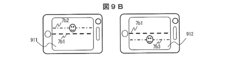
- FIG. 9B is a diagram for explaining the vertical rotation determination.
- a screen 911 is a case where the center position 7b2 in the vertical direction of the face recognized with respect to the setting position 7b1 of the vertical shooting position of the face is on the upper side. It is determined that the face of the subject moves downward in the image of the camera A143).
- the screen 911 is a case where the center position 7b3 in the vertical direction of the face recognized with respect to the setting position 7b1 of the vertical shooting position of the face is on the lower side. It is determined that the subject's face moves upward in the image of the camera A 143 by rotating downward.
- FIG. 9C is a diagram for explaining the left / right rotation determination.
- the screen 921 shows a case where the center position 7c2 in the left-right direction of the recognized face is the left side with respect to the setting position 7c1 of the left-right direction shooting position of the face. It is determined that the face of the subject moves to the right in the image of the camera A143).
- the screen 922 shows the case where the center position 7c3 in the left-right direction of the face recognized with respect to the setting position 7b1 of the left-right direction shooting position of the face is on the right side. It is determined that the subject's face moves to the left in the image of the camera A143.
- the motor constituting the selfie stick 200 is driven according to the shooting conditions set by the user, and it is possible to easily take images of the set face size and face position.
- the information processing apparatus 100 when the self-portrait stick 200 is used to capture an image, the information processing apparatus 100 is arranged at a position where an image that meets a photographing condition indicating a preset size and position of the image can be photographed.
- the shooting stick 200 can be automatically controlled. Thereby, the usability of the selfie stick 200 is improved.
- the present embodiment corresponds to panoramic shooting capable of acquiring a wide range of images larger than the angle of view of the camera in self-shooting.
- the shooting condition setting in this embodiment has setting items related to panoramic shooting.
- An example of the shooting condition setting in this embodiment is shown in FIG.
- panorama shooting on / off, panorama shooting direction, panorama shooting angle (upper and lower panorama angle information when panoramic shooting is performed vertically, and left and right panorama shooting when panoramic shooting is performed horizontally (Including angle information) is provided.
- the user may perform from the operation unit 130 of the information processing apparatus 100.
- the panoramic shooting direction (up / down direction or left / right direction instruction) may be input using the operation input button 205 provided on the operation unit 130 or the selfie stick 200. Therefore, the operation device 130 and the operation input button 205 correspond to a panorama shooting command acquisition unit.
- an input is accepted by the operation input button 205 of the selfie stick 200, and a branch process is performed based on the accepted input (S114). If there is no input in the branch process S114, the process returns to S113 to accept the input.
- a shortening process for driving the motor 204 so that the self-taking rod 200 is in the shortest state is performed (S117), and the self-taking rod control execution program is terminated.
- branch processing is performed according to the panorama shooting on / off setting (S120).
- panorama shooting control processing is performed (S121), and the process returns to S113.
- the panorama shooting control process will be described with reference to the flowchart of FIG.
- Ns images are acquired, and the acquired Ns images are combined to have a wider angle of view than the camera angle of view.
- a panoramic image of the range can be obtained. Therefore, first, the rotation angle step ⁇ s and the step number Ns are calculated (S401).
- Ns INT (Panorama angle setting / angle of view / ⁇ + 0.5)
- ⁇ s (Panorama angle setting ⁇ angle of view) / (Ns ⁇ 1)
- the panorama angle setting is 180 degrees and ⁇ is 0.7
- the rotation angle step ⁇ s becomes smaller than the horizontal angle of view ⁇ h, and the captured Ns images are provided with overlapping portions. Thereby, a natural panoramic image can be obtained when the images are combined.
- the captured image is stored in the temporary storage area 104d of the RAM 104 (S404), and branch processing is performed depending on whether the value of the counter N is equal to the number of rotation steps Ns (S405).
- the branch process is performed by setting the panorama direction (S406).
- the motor 202 is driven to rotate leftward by the rotation angle step ⁇ s (S407).
- the motor 203 is driven to rotate upward by the rotation angle step ⁇ s (S408).
- Ns images stored in the temporary storage area 104d of the RAM 104 are combined (S410), and the combined image is a panoramic image. Is stored in the image information storage area of the storage 110 (S411).
- panoramic photography can be performed by acquiring and synthesizing a plurality of images while controlling the rotation of the motor 202 or 203 constituting the selfie stick 200. Since the horizontal field angle ⁇ h and the vertical field angle ⁇ v are known from the specifications of the camera A 143, the rotation step number Ns and the rotation angle step ⁇ s are calculated in advance according to the panorama angle to be photographed, and the storage 110 is self-photographed. It may be stored in the stick control information storage area 110d1 and read out in S401.
- FIG. 12B is a flowchart showing a flow of panorama shooting processing for imaging a plurality of people.
- the user confirms the number of subjects to be photographed as subjects using the operation unit 130 of the information processing apparatus 100, inputs the number to the information processing apparatus 100, and panoramic direction (left direction, right direction). Direction, up direction, or down direction) and press the shutter button (S114).
- the operation input button 205 may be used to input the panorama direction.
- the panorama shooting control process S121 starts. The set number of photographers and panorama direction information are temporarily stored in the temporary storage area 104d.
- the information processing apparatus 100 rotates the rotation angle ⁇ 1 per one operation of the left-right panorama shooting from the self-shooting stick control information storage area 110d1. Is read (S452-1). If the panorama direction is upward or downward (S451: upward or downward), the information processing apparatus 100 rotates the rotation angle ⁇ 2 per operation of vertical panorama shooting from the selfie stick control information storage area 110d1. Is read (S452-1).
- the read rotation angles ⁇ 1 and ⁇ 2 (the difference between the values of ⁇ 1 and ⁇ 2 is not limited) are used for rotation control described later.
- Camera A 143 captures a still image (S453) and temporarily stores the image (S454).
- the CPU 101 executes the face recognition program 110a, performs face recognition of the still image captured in S453, and counts the number N of people captured in the still image (S455). Then, the number N of persons is compared with the number Ns of persons to be photographed inputted at the input reception S113. If Ns has not been reached (S456: No), the CPU 101 rotates the motor 202 (when panoramic photographing is performed in the horizontal direction). A control instruction signal for rotating at an angle ⁇ 1 is output to the selfie stick control device 250 via the control line 300, and the axis of the selfie stick 200 rotates leftward (or rightward) (S457-1).
- the CPU 101 rotates the motor 203 (when panoramic shooting in the vertical direction) at the rotation angle ⁇ 2.
- the control instruction signal is output to the selfie stick control device 250 via the control line 300, and the axis of the selfie stick 200 rotates upward (or downward) (S457-2).
- the CPU 101 executes a basic operation execution program (including a panorama image synthesis program) 104a to execute an image.
- a composition process is performed (S458), the combined panorama image is saved (S459), and the panorama shooting process according to the present example ends.
- the information processing apparatus 100 sets the number of persons to be photographed in advance (referred to as the set number of persons) in the information processing apparatus 100, so that the information processing apparatus 100 has the same number as the number of photographers.
- the self-shooting stick 200 can be imaged while rotating, and the rotation of the self-taking stick 200 can be stopped when all faces are within the angle of view.
- the user can take a panoramic image containing a desired number of people without manually operating the direction (angle of view) of the information processing apparatus 100 attached to the selfie stick 200.
- ⁇ Third embodiment> when taking a self-portrait with the camera A 143 of the information processing apparatus 100 using the self-portrait stick 200, a person hits another person, or an electric shock due to a high-voltage line such as an overhead line of a train. It corresponds to prevention.
- a detection target In order to avoid contact with the self-shooting stick 200, and to avoid danger as in the case of the end of the station platform, the person or the object to be detected as an obstacle for avoiding danger is collectively referred to as a detection target.
- FIG. 13A is a block diagram showing an internal configuration of the information processing apparatus 100 in the present embodiment.
- FIG. 13B is a software configuration diagram illustrating an example of an internal configuration of the information processing apparatus 100 according to the present embodiment. 13A and 13B, parts having the same functions as those in FIGS. 1A and 1B are denoted by the same reference numerals, and description thereof is omitted.
- a camera C145 is a camera arranged on the opposite side (rear surface) of the display 141 in the same manner as the camera B144.
- the camera B 144 and the camera C 145 are provided at positions separated by, for example, about 1 to several cm. As a result, a shift due to parallax can be detected by comparing the images captured by the respective cameras, so that the distance to the subject in the captured image can be detected.
- the camera C145 and the camera B144 correspond to an obstacle camera (one of distance measuring sensors) when used for obstacle detection.
- the storage 110 stores an obstacle detection program 110e that detects an obstacle based on the distance to the subject detected by the cameras B144 and C145.
- This program is expanded in the RAM 104 as an obstacle detection execution program 104e and executed by the CPU 101.
- an initialization flag Ini_Flag storage area, an obstacle detection flag 1 storage area, and an obstacle detection flag 2 storage area are stored as areas for storing obstacle detection results in the temporary storage area 104d on the RAM 104 in advance. Keep it.
- a camera C145 is added to the existing camera B144 to configure a stereo camera having parallax, and this stereo camera is used as an obstacle sensor.
- the obstacle sensor and the distance measuring sensor are stereo cameras.
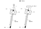
- the peripheral structure such as a person, an object, or a wall may be detected using an ultrasonic sensor (see FIG. 16A).
- the camera B 144 detects light from the human face or body in a certain ratio or more in the angle of view and sends a control line (not shown). Then, a control signal is sent from the information processing apparatus 100 to the selfie stick 200, and control is performed so as to stop the selfie stick 200 from extending.
- the camera B 144 does not detect light from the face or body, or even if it detects light from the face or body, if the area is below a certain ratio within the angle of view, the self-shooting stick 200 is captured by the camera A 143 The stretching may be continued until a certain length is suitable.
- a human sensor infrared sensor
- a control signal is sent from the information processing apparatus 100 to the selfie stick 200 via a control line (not shown), and the selfie stick Control 200 to stop stretching. If the human sensor 166 does not detect the infrared rays emitted by the human body temperature, or if the infrared rays emitted by the human body temperature are detected but the intensity is below a certain value, the self-portrait stick 200 is taken by the camera A143. You may comprise extending
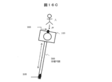
- the microphone 153 of the audio processor 150 As the obstacle sensor, it is conceivable to use the microphone 153 of the audio processor 150 as the sensor 160 located at the tip of the information processing apparatus 100 (see FIG. 16C).
- the voice recognition unit mounted on the audio processor 150 by detecting a specific voice informing the danger of a person such as “dangerous” by the microphone 153 when the self-portrait stick 200 is extended, is collected by the microphone 153. Recognize and extract utterances.
- the voice analysis unit included in the obstacle detection program 110e determines that the extracted utterance is a voice notifying danger, a control signal is sent from the information processing apparatus 100 to the selfie stick 200 via a control line (not shown).
- the self-shooting stick 200 is controlled to stop extending.
- the microphone 153 does not detect a specific voice informing the danger such as “dangerous” from a person, the self-shooting stick 200 continues to extend until the camera A 143 reaches a certain length suitable for shooting.
- the camera B144 of the video processor 140 is used as the sensor 160 located at the tip of the information processing apparatus 100.
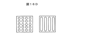
- the obstacle detection program 110e performs pattern recognition processing on the image captured by the camera B 144 and determines that a braille block (FIG. 16D) or a staircase (FIG. 16E) is captured based on the shape and color of the subject. It may be determined that there is an obstacle. In this case, since the size of the braille block and the height of one step of the staircase are estimated, the approximate distance can be estimated based on the size of the braille block and the like shown in the image.
- the magnification of the camera B 144 may be taken into consideration. Since the Braille block is a sign for notifying the visually impaired of the possibility of danger ahead and the need to change the walking direction, when the sensor 160 ahead of the selfie stick 200 detects the Braille block, Control is performed so as to warn a user of the apparatus 100 (for example, a user who is looking at a smartphone while walking) with a display on the display 141 or a sound emitted from the speaker 151, or to stop the self-shooting stick 200 from extending. You may do it.
- the flat portion of the home that previously occupied a certain proportion or more of the area within the angle of view is replaced with the Braille block portion (the shape is registered in advance). Occupying the guidance block unit and the warning block unit), the display 141 and the voice emitted from the speaker 151 to the user of the information processing apparatus 100 (for example, a user who is looking at a smartphone while walking) It may be controlled so as to give a warning or to stop the self-shooting stick 200 from extending.
- the camera B 144 has a certain ratio within the angle of view.
- the light from the wall or object in the above region is detected, and a control signal is sent from the information processing apparatus 100 to the selfie stick 200 via a control line (not shown), and the selfie stick 200 is extended. Control to stop. If the camera B 144 does not detect light from the wall or object, or if the area is less than a certain ratio within the angle of view even if light from the wall or object is detected, the self-shooting stick 200 is captured by the camera A 143. Continue stretching until a constant length appropriate for
- the present invention may also be applied to the case where the home disappears due to coming and the object that has been detected until then disappears.
- the camera B 144 is used to alert the user of the information processing apparatus 100 by detecting no light from the home that previously occupied a certain percentage of the area within the angle of view.
- a control signal may be sent from the information processing apparatus 100 to the selfie stick 200 via a control line (not shown) so that the selfie stick 200 is shortened.
- a control signal is automatically transmitted from the information processing apparatus 100 via a control line (not shown) in a specific place such as a movie theater, a museum, or a train. It is sent to the shooting stick 200 and can be controlled to stop the self-shooting stick 200 from extending.
- a physical quantity (specifically, information indicating how much the angle of the information processing apparatus 100 changes per unit time, that is, the speed at which the object rotates).
- a control signal is sent from the information processing device 100 to the selfie stick 200 via a control line (not shown), and the selfie stick 200 expands. Can be controlled to stop.
- the obstacle detection program 110e includes an object image analysis program, an ultrasonic wave corresponding to the obstacle detection determination process and the members used therefor.
- a distance measurement program, a voice analysis program, and a pattern recognition program are included as appropriate.
- shooting conditions are set (S501).
- input by the operation input button 205 of the selfie stick 200 is received (S502), and branch processing is performed depending on whether or not the on / off switch 205a is input (S503).
- a branching process is performed based on whether or not the difference between the recognized face size and the set face size in the image acquired from the camera A 143 is equal to or smaller than a predetermined value ⁇ s (S506).
- branch processing is performed based on whether the length of the self-shooting stick 200 in the expansion / contraction direction is the longest. (S507).
- the motor 204 is driven to extend the self-taking stick 200 by a predetermined length ⁇ X (S508).
- the obstacle detection execution program 104e executes an obstacle detection process S509 described later.
- the process returns to S505 to perform the vertical rotation control process.
- the obstacle detection flag 1 or the obstacle detection flag 2 is set to 1 (Yes)
- it is assumed that an obstacle related to another person or his / her own danger is detected when the self-shooting stick 200 is extended.
- the display 141 of the information processing apparatus 100 displays a warning for detecting the failure (S511), and performs a shortening process for driving the motor 204 so that the self-shooting stick 200 is in the shortest state (S517).
- the control execution program is terminated.
- the process proceeds to the left / right rotation control process S512. After the left / right rotation control processing, input by the operation input button 205 of the selfie stick 200 is received (S513), and branch processing by the received input is performed (S514). In the branch process S514, if there is no input, the process returns to S513 to accept the input.
- the image captured by the camera A 143 is captured (still image capturing) (S515), and the captured image is stored in the image information storage area 110d3 of the storage 110 (S516). , Return to S513.
- a shortening process for driving the motor 204 so that the selfie stick 200 is in the shortest state is performed (S517), and the selfie stick control execution program is terminated.
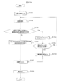
- the obstacle detection processing S509 performed by the obstacle detection execution program 104e will be described with reference to the flowchart of FIG.
- the initialization flag Ini_Flag is “0” (Yes) (Yes), the geomagnetic data Mn acquired in S601 is stored in the temporary storage area 104d of the RAM 104 as the reference value (hereinafter referred to as “reference geomagnetic data”) Mr of the geomagnetic data. (S603), the initialization flag Ini_Flag is set to “1”.
- the initialization flag Ini_Flag is not “0” in the branch process S602 (No), it depends on whether the difference between the geomagnetic data Mn acquired in S601 and the reference geomagnetic data Mr stored in S603 is equal to or larger than a predetermined value ⁇ Mt.
- Branch processing is performed (S605). If the difference between the geomagnetic data Mn and the reference geomagnetic data Mr is equal to or greater than a predetermined value ⁇ Mt (corresponding to the geomagnetic fluctuation threshold) (Yes), the obstacle detection flag 1 is set to “1” (S606). When the difference between the geomagnetic data Mn and the reference geomagnetic data Mr is smaller than the predetermined value ⁇ Mt (No), the obstacle detection flag 1 is set to “0” (S607).
- the images of the camera B 144 and the camera C 145 arranged on the opposite side (rear side) of the display 141 may be captured (S608).
- the distance to the subject in the captured image is detected from the deviation due to the parallax of the acquired images captured by each camera, and the distance Ds to the closest subject is calculated (S609).
- Branch processing is performed based on whether or not the distance Ds to the closest subject is closer than a predetermined distance threshold Dt (S610).
- the obstacle detection flag 2 is set to “1” (S611), and the process is terminated. If the distance Ds to the closest subject is farther than the predetermined distance threshold Dt (No), the obstacle detection flag 2 is set to “0” (S612), and the process is terminated.
- the selfie stick is extended while monitoring the direction of expansion and contraction using an obstacle sensor, avoiding contact with obstacles (people and objects), and preventing falling by monitoring the tip of the home, Self-shooting is possible.
- FIG. 17 is a flowchart showing the processing of the information processing apparatus 100 in the case of preventing photography with backlight in order to take a good photograph in this embodiment.
- the CPU 101 executes the self-portrait stick control execution program 104c and takes a picture using the camera A143 ( Alternatively, it is determined whether the image (displayed on the display 141 of the information processing apparatus 100) is backlit.
- the CPU 101 performs face recognition processing for one frame of the through image captured by the camera A 143 (S1702).
- the illuminance in the face image is less than a predetermined face image illuminance threshold or the illuminance of the face image is less than the illuminance of the background area (S1703: No)
- a light amount correction (backlight correction) process is executed (S1709). For example, a flash is emitted or the illuminance of the display 141 is increased (the amount of light of the backlight is increased).
- the image is captured (S1707), and the image is stored (S1708).
- FIG. 17B is a table showing a shooting condition determination mechanism in the present embodiment.
- the background is bright and the face is bright, it is determined that the light is forward and the self-shooting stick 200 can be extended. If the face is dark even though the background is bright, it is determined that the subject is backlit and the self-shooting stick 200 cannot be extended.
- the background is dark and the face is bright, it is determined that the face is illuminated, and the selfie stick 200 can be extended under the condition that the face is illuminated. Further, when the background is dark and the face is dark, it is determined that the surrounding area is dark, and the self-shooting stick 200 cannot be extended due to danger.
- the control line (not shown)
- 100 Information processing apparatus
- 101 CPU
- 103 ROM
- 104 RAM
- 110 Storage
- 143 Camera A
- 144 Camera B
- 145 Camera C
- 153 Microphone
- 160 Sensor
- 200 Selfie stick
- 201 fixed part
- 202, 203, 204 motor
- 205 operation input button
Landscapes
- Physics & Mathematics (AREA)
- General Physics & Mathematics (AREA)
- Engineering & Computer Science (AREA)
- Multimedia (AREA)
- Signal Processing (AREA)
- Studio Devices (AREA)
Abstract
情報処理装置の支持装置200の長さを調整する際の操作性を向上させる技術を提供する。そのために、情報処理装置100は、撮像部143と、伸縮する棒状の本体部210を含む支持装置200に対して、本体部210を伸長させる伸長命令又は本体部を短縮させる短縮命令を、撮像部143が撮像した撮影画像に基づいて生成する支持装置制御部104cと、支持装置制御部104cが生成した支持装置200に対する命令を、支持装置200に送信する通信部125と、を備える。
Description
本発明は、情報処理装置、情報処理装置の支持装置、及び情報処理装置の支持装置の制御プログラムに関する。
近年、旅行などで恋人や友人と共に写真を撮るために、情報処理端末の支持装置、所謂自撮り棒を使用した撮影が普及してきている。その際にスマートフォンやカメラなどの情報処理装置を取り付けて撮影操作をする必要があるが、撮影する度に自撮り棒に情報処理装置を取り付けて長さ等を調整することは煩雑である。
本技術分野の背景技術として、特許文献1には、課題として、「電子カメラにおいて、自分自身を撮影する際、被写体(自分自身)の距離が自分の腕の長さしかかせげないため、近い絵しか撮ることができない。つまり、景色+自分という絵を撮ることが難しい。」とあり、解決策として「撮影に必要な操作部を備える把持ユニットが、撮像装置本体とは別体で構成され、それぞれに向かい合う面が平行な状態のまま回転・伸長が可能である。また、回転を検出するスイッチを備え、検出することで画像の表示部が撮像装置の背面から前面へ切り替わり、自分撮りを行おうとする撮影者が容易にモニタリングすることができる。(要約抜粋)」というシステムが開示されている。
特許文献1では、情報処理端末と被写体との距離を画角に合わせるために、自撮り棒の長さを手動で調整する必要がある。また、一旦、自撮り棒の長さを調整した後で、自撮り棒を把持しようとすると、情報処理端末が周辺物、例えば人や物に接触しそうになり、再度調整が必要になることもある。このように、自撮り棒の長さの調整に関しては、手動による煩わしさが伴い、操作性について更なる工夫が求められているという実情がある。
本発明は上記課題を解決するものであり、情報処理装置の支持装置の長さを調整する際の操作性を向上させる技術を提供することを目的とする。
上記課題を解決するために、例えば請求の範囲に記載の構成を採用する。本発明は上記課題を解決する手段を複数含んでいるが、その一例を挙げるならば、情報処理装置は、撮像部と、伸縮する棒状の本体部を含む支持装置に対して、前記本体部を伸長させる伸長命令又は前記本体部を短縮させる短縮命令を、前記撮像部が撮像した撮影画像に基づいて生成する支持装置制御部と、前記支持装置制御部が生成した前記支持装置に対する命令を、前記支持装置に送信する通信部と、を備えることを特徴とする。
本発明によれば、情報処理装置の支持装置の長さを調整する際の操作性を向上させる技術を提供することができる。なお、上記した以外の課題、構成及び効果は、以下の実施形態の説明により明らかにされる。
以下、図面を用いて本発明の実施形態について説明する。本実施形態は、撮像部を有する情報処理装置と、当該情報処理装置を支持する自撮り棒(情報処理装置の支持装置に相当する)に内蔵された自撮り棒制御装置とを通信接続した撮像システム、それを用いた自撮り棒制御方法、また撮像システムに含まれる情報処理装置や自撮り棒に関する。
<第一実施形態>
図1Aは、本実施形態における情報処理装置100の内部構成の一例を示すブロック図である。図1Aにおいて、情報処理装置100は、CPU(Central Processing Unit)101、システムバス102、ROM(Read Only Memory)103、RAM(Random Access Memory)104、ストレージ110、通信処理器120、拡張インターフェイス125、操作器130、ビデオプロセッサ140、オーディオプロセッサ150、センサ160で構成される。
図1Aは、本実施形態における情報処理装置100の内部構成の一例を示すブロック図である。図1Aにおいて、情報処理装置100は、CPU(Central Processing Unit)101、システムバス102、ROM(Read Only Memory)103、RAM(Random Access Memory)104、ストレージ110、通信処理器120、拡張インターフェイス125、操作器130、ビデオプロセッサ140、オーディオプロセッサ150、センサ160で構成される。
CPU101は、情報処理装置100全体を制御するマイクロプロセッサユニットである。システムバス102はCPU101と情報処理装置100内の各動作ブロックとの間でデータ送受信を行うためのデータ通信路である。
ROM103は、オペレーティングシステムなどの基本動作プログラムやその他の動作プログラムが格納されたメモリであり、例えばEEPROM(Electrically Erasable and Programmable Read Only Memory)やフラッシュROMのような書き換え可能なROMが用いられる。RAM104は基本動作プログラムやその他の動作プログラム実行時のワークエリアとなる。ROM103及びRAM104はCPU101と一体構成であっても良い。また、ROM103は、図1Aに示したような独立構成とはせず、ストレージ110内の一部記憶領域を使用するようにしても良い。
ストレージ110は、情報処理装置100の動作プログラムや動作設定値、情報処理装置100で撮影した画像、情報処理装置100のユーザの情報等を記憶する。
ストレージ110の一部領域を以ってROM103の機能の全部又は一部を代替しても良い。また、ストレージ110は、情報処理装置100に外部から電源が供給されていない状態であっても記憶している情報を保持する必要がある。従って、例えば、フラッシュROMやSSD(Solid State Drive)、HDD(Hard Disk Drive)等のデバイスが用いられる。
なお、ROM103やストレージ110に記憶された前記各動作プログラムは、広域公衆ネットワーク上の各サーバ装置(図示せず)からのダウンロード処理により更新及び機能拡張することが可能であるものとする。
通信処理器120は、LAN(Local Area Network)通信器121、電話網通信器122、NFC(Near Field Communication)通信器123、Bluetooth(登録商標)通信器124を含んで構成される。LAN通信器121はWi-Fi(登録商標)等による無線接続によりアクセスポイント(AP)装置(図示せず)を介して広域公衆ネットワークに接続され、広域公衆ネットワーク上の各サーバ装置とデータの送受信を行う。電話網通信器122は移動体電話通信網の基地局(図示せず)との無線通信により、電話通信(通話)及びデータの送受信を行う。NFC通信器123は対応するリーダ/ライタとの近接時に無線通信を行う。Bluetooth通信器124は対応する端末と無線通信によりデータの送受信を行う。LAN通信器121、電話網通信器122、NFC通信器123、Bluetooth通信器124は、それぞれ符号回路や復号回路、アンテナ等を備えるものとする。また、通信処理器120が、赤外線通信や、その他の通信器を更に備えていても良い。
拡張インターフェイス125は、情報処理装置100の機能を拡張するためのインターフェイス群であり、本実施形態では、映像/音声インターフェイス、USB(Universal Serial Bus)インターフェイス、メモリインタフェース等で構成されるものとする。映像/音声インターフェイスは、外部映像/音声出力機器からの映像信号/音声信号の入力、外部映像/音声入力機器への映像信号/音声信号の出力、等を行う。USBインターフェイスは、PC(Personal Computer)等と接続してデータの送受信を行う。また、キーボードやその他のUSB機器の接続を行っても良い。メモリインタフェースはメモリカードやその他のメモリ媒体を接続してデータの送受信を行う。
操作器130は、情報処理装置100に対する操作指示の入力を行う指示入力装置であり、本実施形態では、ディスプレイ141に重ねて配置したタッチパネル及びボタンスイッチを並べた操作キーで構成されるものとする。なお、そのいずれか一方のみであっても良いし、拡張インターフェイス125に接続したキーボード等を用いて情報処理装置100の操作を行っても良い。また、有線通信又は無線通信により接続された別体の携帯端末機器を用いて情報処理装置100の操作を行っても良い。また、前記タッチパネル機能はディスプレイ141が備え持っているものであっても良い。
ビデオプロセッサ140は、ディスプレイ141、画像信号プロセッサ142、カメラA143(自撮り棒の伸縮制御に用いる撮影部に相当する)、カメラB144で構成される。カメラA143は、ディスプレイ141と同じ面(前面)に配置されたカメラであり、例えばカメラA143で撮影した自分の顔をディスプレイ141で確認して撮影する、所謂自撮りに使用される。カメラB144は、ディスプレイ141の反対側(背面)に配置されたカメラである。
ディスプレイ141は、例えば液晶パネル等の表示デバイスであり、画像信号プロセッサ142で処理した画像データを表示し情報処理装置100のユーザに提供する。画像信号プロセッサ142は図示を省略したビデオRAMを備え、ビデオRAMに入力された画像データに基づいてディスプレイ141が駆動される。また、画像信号プロセッサ142は、必要に応じてフォーマット変換、メニューやその他のOSD(On-Screen Display)信号の重畳処理等を行う機能を有するものとする。カメラA143及びカメラB144は、CCD(Charge-Coupled Device)やCMOS(Complementary Metal Oxide Semiconductor)センサ等の電子デバイスを用いてレンズから入力した光を電気信号に変換することにより、周囲や対象物の画像データを入力する撮像装置として機能するカメラユニットである。
オーディオプロセッサ150は、スピーカ151、音声信号プロセッサ152、マイク153を含んで構成される。スピーカ151は、音声信号プロセッサ152で処理した音声信号を情報処理装置100のユーザに提供する。マイク153は、ユーザの声などを音声データに変換して入力する。
センサ160は、情報処理装置100の状態を検出するためのセンサ群であり、本実施形態では、GPS(Global Positioning System)受信器161、ジャイロセンサ162、地磁気センサ163、加速度センサ164、照度センサ165、人感センサ166を含んで構成される。これらのセンサ群により、情報処理装置100の位置、傾き、方角、動き、及び周囲の明るさ等を検出することが可能となる。また、情報処理装置100が、気圧センサ等、圧力センサ他のセンサを更に備えていても良い。なお、位置情報の取得は、GPS受信器161により取得するが、GPS電波が入りにくい場所等で取得できない場合は、LAN通信器121によりWi-FiのAP装置での位置情報から取得してもよいし、電話網通信器122により基地局情報から取得してもよい。
情報処理装置100は、携帯電話やスマートフォン、デジタルスチルカメラや動画撮影可能なビデオカメラ、又はその他の携帯用デジタル機器であっても良い。
なお、図1Aに示した情報処理装置100の構成例は、通信処理器120等、本実施形態に必須ではない構成も多数含んでいるが、これらが備えられていない構成であっても本実施形態の効果を損なうことはない。また、デジタル放送受信機能や電子マネー決済機能等、図示していない構成が更に加えられていても良い。
図1Bは、本実施形態における情報処理装置100の内部構成の一例を示すソフトウェア構成図である。図1Bにおいて、ROM103は、オペレーティングシステムなどの基本動作プログラム103aと、その他の動作プログラム103bを含んで構成されている。また、ストレージ110にはカメラA143或いはカメラB144で撮影した画像から顔部分を認識するための顔認識プログラム110a(CPU101の実行状態において顔認識部を構成する)、自撮り棒の伸縮や回転の制御を行う自撮り棒制御プログラム110b、その他の動作プログラム110cが記憶されている。また、ストレージ110には各種情報/データ記憶領域110dが設けられており、自撮り棒の制御を行うための設定値などの情報を記憶する自撮り棒制御情報記憶領域110d1、ユーザの名前やユーザを認識するための顔認識情報等を記憶するユーザ情報記憶領域110d2、撮影した画像等を記憶する画像情報記憶領域110d3を有している。
ROM103及びストレージ110に記憶されたプログラムは、それぞれ、基本動作プログラムを実行する基本動作実行プログラム104aと、カメラA143で撮像した画像から顔部分を認識するための顔認識実行プログラム104b、自撮り棒200の伸縮や回転の制御を行う自撮り棒制御実行プログラム104cとしてRAM104に展開され、CPU101により実行される。これにより支持装置制御部が構成される。また、RAM104の一部は各プログラム実行時に必要に応じてデータを一時的に保持する一時記憶領域104dを備えるものとする。なお、ストレージ110に設けた自撮り棒制御情報記憶領域110d1はRAM104の一時記憶領域104dに設けてもよい。
図2Aに本実施形態における自撮り棒200の外観図を示す。自撮り棒200は、棒状の本体部210と、本体部210の一端に備えられたユーザが把持する把持部220と、本体部210の他端に備えられた情報処理装置100を着脱可能に取り付ける装置取付部230とを含んで構成される。
本体部210は、筒状部材211及びその中に収容される棒状部材212と、棒状部材212を筒状部材211から繰り出したりまた収容する伸縮機構213(例えばラック・アンド・ピニオンのような機構)及びその伸縮機構213を駆動させるモータ204(伸縮駆動装置に相当する)を備える。
装置取付部230は、棒状部材212の先端部231、先端部231から棒状部材212の軸方向に対して直交する方向に突出し、棒状部材212の軸方向と直交する回転軸を有する第一回転軸233、第一回転軸233を介して先端部231と連結された支持部232、支持部232から棒状部材212の軸方向と平行な方向に向かって突出し、棒状部材212の軸方向と平行な回転軸を有する第二回転軸234、及び第二回転軸234を介して支持部232と連結され、情報処理装置100を着脱自在に取り付ける固定部201を備える。
先端部231の内部には第一回転軸233の一端が収容され、第一回転軸233を回転駆動させるモータ203(第一駆動装置に相当する)が先端部231に収容されている。支持部232の内部には第二回転軸234の一端が収容され、第二回転軸234を回転駆動させるモータ202((第二駆動装置に相当する))が支持部232に収容されている。第一回転軸233は、固定部201に取り付けられた情報処理装置100を上下方向(チルト方向)に回転させる。第二回転軸234は、固定部201に取り付けられた情報処理装置100を左右方向(パン方向)に回転させる。
把持部220には、操作入力ボタン205として、自撮り棒200の伸長の開始終了の操作入力を行うオン/オフスイッチ205a、及び情報処理装置100にカメラA143のシャッターの操作入力を行うシャッターボタン205bを備える。なお、図2Aの外観図では本発明の説明に必要な部分のみを記しているが、図示していないバッテリー等からなる電源部や、モータを駆動する駆動制御装置などを有するものとする。
図2Bは自撮り棒200と情報処理装置100との接続関係を示す機能ブロック図である。自撮り棒200は、モータ202、203、204に対して駆動制御信号を出力する自撮り棒制御装置250(伸縮駆動制御装置に相当する)を有する。自撮り棒制御装置250は、CPU251、ROM252、RAM253、情報処理装置100と通信接続するための通信インターフェイス254、自撮り棒200内の各構成部材、例えばモータ202、203、204、オン/オフスイッチ205a、及びシャッターボタン205bと通信接続する外部インターフェイス255、及び自撮り棒制御装置250内の各構成要素を接続するバス256を含んで構成される。
情報処理装置100と自撮り棒200とは、情報処理装置100の拡張インターフェイス125と自撮り棒200の通信インターフェイス254とを制御線300を介して通信接続される。よって拡張インターフェイス125は装置通信部を構成する。拡張インターフェイス125と自撮り棒200の通信インターフェイス254は、制御線300の種類に応じた構成となるが、拡張インターフェイス125と自撮り棒200の通信インターフェイス254(自撮り棒通信部に相当する)はUSBインターフェイスにより構成し、制御線300として有線制御線用いて構成してもよい。
また自撮り棒制御装置250にもBluetooth通信器257を設け、情報処理装置100のBluetooth通信器124と無線により制御信号及び操作信号の入出力を行うようにしてもよい。この場合、制御線300は無線ネットワークにより構成されることとなる。
制御線300を介して情報処理装置100から自撮り棒200に対して自撮り棒200の伸縮、上下回転、左右回転を行うための制御信号が出力され、自撮り棒200から情報処理装置100に対して操作入力ボタン205による情報処理装置100のカメラA143のシャッターの操作信号が出力される。
図3のフローチャートを用いて本実施形態における自撮り棒制御実行プログラム104cの動作について説明する。
図3に示す動作は、自撮り棒200及び情報処理装置100の主電源が投入されると開始する。情報処理装置100に主電源が投入されるとカメラA143又はカメラB144から画像信号が画像信号プロセッサ142に出力され、ディスプレイ141にスルー画像が表示される。以後、カメラA143又はカメラB144の機能が停止されたり、撮像された静止画像を表示したり、情報処理装置100の主電源がOFFにされるまで、スルー画像がディスプレイ141に表示されるものとする。なお、カメラA143又はカメラB144のいずれの画像がディスプレイ141に表示されるかは、情報処理装置100の初期設定やユーザ設定により決定できるものとする。
ユーザは、まず撮影条件設定を行う(S101)。撮影条件設定の例を図4及び図5を用いて説明する。図4は撮影条件設定の例であり自撮り棒制御情報記憶領域110d1に記憶された撮影条件情報の一例である。よって、自撮り棒制御情報記憶領域110d1は撮影条件記憶部に相当する。撮影条件情報は、撮影する顔の大きさ(顔画像規定値)、撮影画像における顔の上下方向撮影位置情報、左右方向撮影位置情報、ユーザ認証のオン/オフ設定情報を含む。
図5Aは撮影時の顔の大きさの設定例であり、ここでは「Large/Middle/Small」の3段階の設定の中から選択するものとする。ここでは、顔の上下方向の大きさにより大きさを指定するものとする。
図5Bは撮影時の上下方向の顔の位置の設定例であり、ここでは「High/Middle/Low」の3つの設定の中から選択するものとする。
図5Cは撮影時の左右方向の顔の位置の設定例であり、ここでは「Left/Center/Right」の3つの設定の中から選択するものとする。また、図4において「任意」の設定を選択した場合にはディスプレイ141に重ねて配置したタッチパネル等の操作器130によりユーザが撮影時の顔の大きさや顔の位置を任意に設定できるものとする。
次に、自撮り棒200の操作入力ボタンによる入力の受け付けを行い(S102)、オン/オフスイッチ205aの入力の有無により分岐処理を行う(S103)。
分岐処理S103において、オン/オフスイッチ205aの入力がない場合(No)にはS102に戻って入力の受け付けを行う。オン/オフスイッチ205aの入力が有の場合(Yes)には、上下回転制御処理を行なう(S104)。上下回転制御処理S104では後述するように、カメラA143から取得した画像に基づいて、撮影した画像におけるユーザの顔の位置が設定した上下方向の位置となるようにモータ203を駆動する。
次に、カメラA143から取得した画像において認識した顔の大きさと図4で設定した顔の大きさの差が所定の値Δs以下であるか否かにより分岐処理を行う(S105)。認識した顔の大きさと設定した顔の大きさの差が所定の値Δs以上の場合(No)には、認識した顔の大きさと設定した顔の大きさに基づいて伸縮判定処理を行い(S106)、判定結果に基づいて分岐処理を行う(S107)。
分岐処理S107において、CPU101が自撮り棒200を「伸長する」と判定した場合には、自撮り棒200の伸縮方向の長さが最も長い状態か否かによる分岐処理を行う(S108)。分岐処理S108において、自撮り棒200の伸縮方向の長さが最も長い状態ではない場合(No)には、CPU101が伸長命令を生成し、自撮り棒制御装置250に出力する。自撮り棒制御装置250はモータ204を駆動制御し、モータ204の回転に伴って伸縮機構213が棒状部材212を筒状部材211の外側に繰り出すことで自撮り棒200を所定の長さΔXだけ伸長(S109)させる。その後、S104に戻って上下回転制御処理を行う。ΔXは初期設定された自撮り棒200の伸縮方向への増減量であり、本実施形態ではΔX動かしてS104へ戻り、再度、被写体像における顔画像の大きさと設定値とを比較し(S105)、その結果に応じて伸縮動作を続行又は停止するという、所謂フィードバック制御を例に挙げて説明する。この処理により、自撮り棒200の伸縮動作をΔXずつ行うので後述する自撮り棒200と周辺の人や物との干渉を防止する処理とを並行して行い、顔画像が設定値に達する前であっても自撮り棒200の伸縮動作を停止させやすくなる。
伸縮動作の他例として、被写体画像において認識した顔の大きさ及び図4で設定した顔の大きさの差と、自撮り棒の伸縮量と、を関連付けた伸縮量情報を予め自撮り棒制御情報記憶領域110d1に記憶しておき、CPU101が伸縮判定処理において大きさの差に対応した伸縮量を求め、その伸縮量を示す制御信号を自撮り棒制御装置250に出力するように構成してもよい。この処理によれば、自撮り棒200の伸縮動作中に顔認識処理などの付随する画像処理が不要となるので、自撮り棒200の伸縮動作における処理負荷を下げることができる。特に自撮り棒200の周辺に人や物がないところでは、より高速に自撮り棒200の伸縮動作が行える。自撮り棒200の伸縮動作例は本実施形態に限定されず、また一つの自撮り棒200に複数の伸縮処理を行うプログラムを搭載し、ユーザがセーフティモード(フィードバック制御でゆっくり伸縮動作させるモード)と高速モード(伸縮量を算出して自撮り棒200を伸縮させるモード)とを選択できるように構成してもよい。
分岐処理S106において「縮める」と判定した場合には、自撮り棒200の伸縮方向の長さが最も短い状態か否かによる分岐処理を行う(S110)。分岐処理S110において、自撮り棒200の伸縮方向の長さが最も短い状態ではない場合(No)には、CPU101が短縮命令を生成して自撮り棒制御装置250へ出力し、自撮り棒制御装置250がモータ204を駆動し、伸縮機構213が棒状部材212を筒状部材211内に収容する方向に稼働して自撮り棒200を所定の長さΔXだけ縮めさせる(S111)。その後、S104に戻って上下回転制御処理を行う。
分岐処理S105において認識した顔の大きさと設定した顔の大きさの差が所定の値Δs以下の場合(Yes)、分岐処理S108において自撮り棒200の伸縮方向の長さが最も長い状態の場合(Yes),及び分岐処理S110において自撮り棒200の伸縮方向の長さが最も短い状態の場合(Yes)には左右回転制御処理S112に進む。
左右回転制御処理S112では後述するように、カメラA143で取得した画像に基づいて、撮影した画像におけるユーザの顔の位置が設定した左右方向の位置となるようにモータ202を駆動する。
左右回転制御処理S112後、自撮り棒200の操作入力ボタン205による入力の受け付けを行い(S113)、受け付けた入力による分岐処理を行う(S114)。分岐処理S114において、入力がない場合にはS113に戻って入力の受け付けを行う。シャッターボタン205bの入力を受け付けた場合には、カメラA143で撮影した画像の取り込み(静止画像の撮像)を行い(S115)、取り込んだ画像(静止画像)をストレージ110の画像情報記憶領域110d3に保存し(S116)、S113に戻る。オン/オフスイッチ205aの入力を受け付けた場合には、自撮り棒200を最も短い状態になるようにモータ204を駆動する短縮処理を行い(S117)、自撮り棒制御実行プログラムを終了する。
図8A及び図8Bに自撮り棒200を伸長させたときの情報処理装置100のカメラA143における上下方向の画角の中心を示す。
図8Aは自撮り棒200を伸長させたときに上下回転制御を行わない場合であり、伸長する前の上下方向の画角の中心位置6a1に対して、伸長後は上下方向の画角の中心位置6a2に変位し、ユーザの顔の上下方向の位置が変わることになる。図8Bは自撮り棒200を伸長させたときにθvだけ上下回転制御を行った場合であり、伸長する前の上下方向の画角の中心位置6b1に対して、伸長後の上下方向の画角の中心が6b3となり、カメラA143の撮影画像中におけるユーザの顔の上下方向の位置が変わらないようにすることができる。図3に示す自撮り棒制御実行プログラムでは自撮り棒200を伸縮させたときに、上下回転制御処理S104を行うことで、撮影した画像におけるユーザの顔の位置を設定した上下方向の位置とすることが可能となる。
図3の上下回転制御処理S104について、図6のフローチャートを用いて説明する。図6において、まず、カメラA143で撮影したスルー画像の取り込みを行い(S201)、顔認識実行プログラム104bにより取得したスルー画像に含まれる1フレームを読み込んで、顔が写っている部分の認識を行う(S202)。
次に、認識した顔画像の上下方向の中心位置と図4及び図5Bに示した上下方向撮影位置の設定とのずれに基づいて分岐処理を行う(S203)。分岐処理S203において、顔画像の上下方向の中心位置と設定した上下方向撮影位置のずれが所定の範囲Δvより大きい場合(No)には、顔画像の上下方向の中心位置と設定した上下方向撮影位置より上下回転判定処理を行い(S204)、判定結果に基づいて分岐処理を行う(S205)。
分岐処理S205において、上回転と判定した場合には、CPU101は自撮り棒制御装置250に対して上方向回転命令を出力し、自撮り棒制御装置250が上方向に所定の角度Δθv回転するようにモータ203を駆動し(S206)、S201に戻って再度カメラA143で撮影した画像の取り込みを行う。下回転と判定した場合には、CPU101は自撮り棒制御装置250に対して下方向回転命令を出力し、自撮り棒制御装置250が下方向に所定の角度Δθv回転するようにモータ203を駆動し(S207)、S201に戻って再度カメラA143で撮影した画像の取り込みを行う。
分岐処理S203において、顔画像の上下方向の中心位置と設定した上下方向撮影位置のずれが所定の範囲Δvより小さい場合(Yes)には処理を終了してS105へ進む。
図3の左右回転制御処理S112について、図7のフローチャートを用いて説明する。図7において、まず、カメラA143で撮影したスルー画像の取り込みを行い(S301)、顔認識実行プログラム104bにより取得したスルー画像に含まれる1フレームを読み込んで、顔が写っている部分の認識を行う(S302)。
次に、認識した顔画像の左右方向の中心位置と図4及び図5Cに示した左右方向撮影位置の設定とのずれに基づいて分岐処理を行う(S303)。分岐処理S303において、顔画像の左右方向の中心位置と設定した左右方向撮影位置のずれが所定の範囲Δhより大きい場合(No)には、顔画像の左右方向の中心位置と設定した左右方向撮影位置より左右方向回転判定処理を行い(S304)、判定結果に基づいて分岐処理を行う(S305)。
分岐処理S305において、右回転と判定した場合には、CPU101は自撮り棒制御装置250に対して右方向回転命令を出力し、自撮り棒制御装置250が右方向に所定の角度Δθh回転するようにモータ202を駆動し(SS306)、S301に戻って再度カメラA143で撮影した画像の取り込みを行う。左回転と判定した場合には、CPU101は自撮り棒制御装置250に対して左方向回転命令を出力し、自撮り棒制御装置250が左方向に所定の角度Δθh回転するようにモータ202を駆動し(S307)、S301に戻って再度カメラA143で撮影した画像の取り込みを行う。
分岐処理S303において、顔画像の左右方向の中心位置と設定した左右方向撮影位置のずれが所定の範囲Δhより小さい場合(Yes)には処理を終了してS113へ進む。
なお、S202或いはS302の顔認識において、撮影条件設定のユーザ認証の設定をオンしている場合には、予めユーザの顔を特定するための情報としてユーザ情報記憶領域110d2に記憶された情報を用いて、ユーザの顔が写っている部分の認識を行う。これにより、複数の顔が写っている場合に、ユーザの顔を選択して撮影することができる。
伸縮判定処理(S105)、上下回転判定処理(S204)、左右回転判定処理(S304)について、図9を用いて説明する。
図9Aは伸縮判定を説明する図である。画面901は顔の大きさの設定幅7a1に対して認識した顔7a2の大きさが大きい場合であり、伸縮判定処理では「伸ばす」(自撮り棒200が伸びることで情報処理装置100が遠ざかり被写体の顔が小さく撮像される)と判定する。画面902は顔の大きさの設定幅7a1に対して認識した顔7a3の大きさが小さい場合であり、伸縮判定処理では「縮める」(自撮り棒200が縮むことで情報処理装置100が近づき被写体の顔が大きく撮像される)と判定する。
図9Bは上下回転判定を説明する図である。画面911は顔の上下方向撮影位置の設定位置7b1に対して認識した顔の上下方向の中心位置7b2が上側の場合であり、上下回転判定処理では「上回転」(自撮り棒200が上回転することで被写体の顔がカメラA143の画像内において下方向に移動する)と判定する。画面911は、顔の上下方向撮影位置の設定位置7b1に対して認識した顔の上下方向の中心位置7b3が下側の場合であり、上下回転判定処理では「下回転」(自撮り棒200が下回転することで被写体の顔がカメラA143の画像内において上方向に移動する)と判定する。
図9Cは左右回転判定を説明する図である。画面921は顔の左右方向撮影位置の設定位置7c1に対して認識した顔の左右方向の中心位置7c2が左側の場合であり、左右回転判定処理では「左回転」(自撮り棒200が左回転することで被写体の顔がカメラA143の画像内において右方向に移動する)と判定する。画面922は顔の左右方向撮影位置の設定位置7b1に対して認識した顔の左右方向の中心位置7c3が右側の場合であり、左右回転判定処理では「右回転」(自撮り棒200が右回転することで被写体の顔がカメラA143の画像内において左方向に移動する)と判定する。
以上の実施形態ではユーザが設定した撮影条件に従って自撮り棒200を構成するモータが駆動され、設定した顔の大きさ及び顔の位置の画像を容易に撮影することが可能となる。
本実施形態によれば、自撮り棒200を用いて撮像する際に、予め設定した画像の大きさや位置を示す撮影条件に合った画像が撮影できる位置に情報処理装置100を配置させるよう、自撮り棒200を自動制御することができる。これにより、自撮り棒200の使い勝手が向上する。
<第二実施形態>
本実施形態は自撮りにおいて、カメラの画角以上の広い範囲の画像を取得することが可能なパノラマ撮影に対応するものである。
本実施形態は自撮りにおいて、カメラの画角以上の広い範囲の画像を取得することが可能なパノラマ撮影に対応するものである。
図10のフローチャートを用いて本実施形態における自撮り棒制御実行プログラム104cの動作について説明する。
図10において、S100からS112は図3の処理と同じであり、説明を省略する。なお、本実施形態における撮影条件設定ではパノラマ撮影に関する設定項目を有するものとする。本実施形態における撮影条件設定の例を図11に示す。図4の撮影条件設定に加えてパノラマ撮影のオン/オフ、パノラマ撮影の方向、パノラマ撮影する角度(上下方向にパノラマ撮影する際の上下パノラマ角度情報、及び左右方向にパノラマ撮影する際の左右パノラマ角度情報を含む)の設定が設けられている。上記パノラマ撮影の撮影条件設定に際しては、ユーザが情報処理装置100の操作器130から行ってもよい。またパノラマ撮影の方向(上下方向、また左右方向の指示)も操作器130や自撮り棒200に備えられた操作入力ボタン205を用いて入力を行ってもよい。よって、操作器130や操作入力ボタン205はパノラマ撮影命令取得部に相当する。
図10のS113において、自撮り棒200の操作入力ボタン205による入力の受け付けを行い、受け付けた入力による分岐処理を行う(S114)。分岐処理S114において、入力がない場合にはS113に戻って入力の受け付けを行う。オン/オフスイッチ205aの入力を受け付けた場合には、自撮り棒200を最も短い状態になるようにモータ204を駆動する短縮処理を行い(S117)、自撮り棒制御実行プログラムを終了する。
シャッターボタン205bの入力を受け付けた場合には、パノラマ撮影オン/オフの設定よる分岐処理を行う(S120)。
分岐処理S120において、パノラマ撮影の設定がオフの場合には、カメラA143で撮影した画像の取り込み(静止画像の撮像)を行い(S115)、取り込んだ画像をストレージ110の画像情報記憶領域110d3に保存し(S116)、S113に戻る。
パノラマ撮影の設定がオンの場合にはパノラマ撮影制御処理を行い(S121)、S113に戻る。
パノラマ撮影制御処理について、図12Aのフローチャートを用いて説明する。パノラマ撮影では情報処理装置100をパノラマ撮影の方向に所定の回転角度ステップθsだけ回転させる毎にNs枚の画像を取得し、取得したNs枚の画像を合成することでカメラの画角以上の広い範囲のパノラマ撮影画像を得ることができる。このため、まず回転角度ステップθsとステップ数Nsを計算する(S401)。
回転ステップ数Ns、回転角度ステップθsは例えば次式(1)、(2)により計算を行う。
Ns=INT(パノラマ角度設定/画角/α+0.5)・・・(1)
θs=(パノラマ角度設定―画角)/(Ns-1)・・・(2)
Ns=INT(パノラマ角度設定/画角/α+0.5)・・・(1)
θs=(パノラマ角度設定―画角)/(Ns-1)・・・(2)
ここで、画角は次式(3)、(4)によって与えられる。
左右方向画角θh=2 x arctan(撮像素子横幅/焦点距離) ・・・(3)
上下方向画角θv =2 x arctan(撮像素子縦幅/焦点距離) ・・・(4)
左右方向画角θh=2 x arctan(撮像素子横幅/焦点距離) ・・・(3)
上下方向画角θv =2 x arctan(撮像素子縦幅/焦点距離) ・・・(4)
例えば、カメラA143の撮像素子の大きさが横4.8mm、縦3.6mm、焦点距離4mmとすると、左右方向画角θh=62度、上下方向画角θv=48度となる。パノラマ角度設定を180度とし、αを0.7とすると、左右方向のパノラマ撮影を行う場合の回転ステップ数Ns=4、回転角度ステップθs=39度となる。αを1以下に設定することで、回転角度ステップθsは左右方向画角θhより小さくなり、撮影したNs枚の画像は重なった部分が設けられる。これにより、画像を合成した時に自然なパノラマ撮影画像を得ることができる。
次にカウンタN=1とし(S402)、カメラA143で撮像した静止画像を取込む(S403)。取り込んだ画像をRAM104の一時記憶領域104dに保存し(S404)、カウンタNの値が回転ステップ数Nsに等しいか否かによる分岐処理を行う(S405)。
分岐処理S405において、カウンタNの値が回転ステップ数Nsに等しくない場合(No)には、パノラマ方向の設定により分岐処理を行う(S406)。パノラマ方向の設定が左右方向の場合には、モータ202を駆動して、回転角度ステップθsだけ左方向に回転させる(S407)。パノラマ方向の設定が上下方向の場合には、モータ203を駆動して、回転角度ステップθsだけ上方向に回転させる(S408)。左方向或いは上方向に回転させた後、カウンタN=N+1として(S409)、S403に戻り、カメラA143で撮像した静止画像を取込む。
分岐処理S405において、カウンタNの値が回転ステップ数Nsに等しい場合(Yes)には、RAM104の一時記憶領域104dに保存したNs枚の画像を合成し(S410)、合成した画像をパノラマ撮影画像としてストレージ110の画像情報記憶領域に保存する(S411)。
次にパノラマ撮影により回転させたモータの角度を元に戻すため、以下の処理を行う。まず、パノラマ方向の設定により分岐処理を行う(S412)。パノラマ方向の設定が左右方向の場合には、モータ202を駆動して、回転角度ステップθsだけ右方向に回転させる(S413)。パノラマ方向の設定が上下方向の場合には、モータ203を駆動して、回転角度ステップθsだけ下方向に回転させる(S414)。右方向或いは下方向に回転させた後、カウンタN=N―1とし(S415)、カウンタNが1に等しいか否かによる分岐処理を行う(S416)。
分岐処理S416において、カウンタNが1に等しくない場合(No)にはS412に戻り、カウンタNが1に等しい場合(Yes)には処理を終了する。
以上の処理により、自撮り棒200を構成するモータ202或いは203の回転を制御しながら複数の画像を取得し、合成することでパノラマ撮影が可能となる。なお、左右方向画角θh、上下方向画角θvはカメラA143の仕様により既知であることから、撮影するパノラマ角度に応じて予め回転ステップ数Ns、回転角度ステップθs計算し、ストレージ110の自撮り棒制御情報記憶領域110d1に記憶しておき、S401ではこれを読みだすようにしてもよい。
パノラマ撮影の別例として、複数人を撮像するためのパノラマ撮影の処理動作について図12Bを参照して説明する。図12Bは複数人を撮像するためのパノラマ撮影の処理のン流れを示すフローチャートである。
ユーザは、図10の入力受付S113において、ユーザが情報処理装置100の操作器130を用いて被写体として撮影する対象の人数を確認して情報処理装置100に入力するとともにパノラマ方向(左方向、右方向、上方向、又は下方向)を入力し、シャッターボタンを押す(S114)。パノラマ方向の入力は操作入力ボタン205を用いてもよい。パノラマ撮影がオンになっている場合(S120:オン)、パノラマ撮影制御処理S121が開始する。設定した撮影人数及びパノラマ方向情報は、一時記憶領域104dに一時的に記憶される。
パノラマ方向が左方向又は右方向であれば(S451:左方向又は右方向)であれば、情報処理装置100が自撮り棒制御情報記憶領域110d1から左右方向パノラマ撮影の1動作当たりの回転角度θ1を読み込む(S452―1)。パノラマ方向が上方向又は下方向であれば(S451:上方向又は下方向)であれば、情報処理装置100が自撮り棒制御情報記憶領域110d1から上下方向パノラマ撮影の1動作当たりの回転角度θ2を読み込む(S452―1)。ここで読み込んだ回転角度θ1、θ2(θ1、θ2の値の異同は限定されない)は後述する回転制御に用いる。
カメラA143は静止画像を取り込み(S453)、画像を一時保存する(S454)。
CPU101は、顔認識プログラム110aを実行し、S453で取り込んだ静止画像の顔認識を行い、静止画像に撮像されている人数Nをカウントする(S455)。そして人数Nと入力受付S113で入力された撮影対象者の人数Nsとを比較し、Nsに達していなければ(S456:No)、CPU101は、モータ202(横方向にパノラマ撮影する場合)を回転角度θ1で回転させるための制御指示信号を制御線300を介して自撮り棒制御装置250に出力し、自撮り棒200の軸が左方向(又は右方向)に回転する(S457-1)。同様に、上方向または下方向のパノラマ撮影でも、人数NがNsに達していなければ(S456:No)、CPU101は、モータ203(上下方向にパノラマ撮影する場合)を回転角度θ2で回転させるための制御指示信号を制御線300を介して自撮り棒制御装置250に出力し、自撮り棒200の軸が上方向(又は下方向)に回転する(S457-2)。
そして再度S453に戻り静止画像を撮像する。
撮像された人数Nが入力受付S113で入力された撮影対象者の人数Nsに達すると(S456:Yes)、CPU101は基本動作実行プログラム(パノラマ画像の画像合成プログラムを含む)104aを実行して画像合成処理を行い(S458)、合成後のパノラマ画像を保存して(S459)、本例に係るパノラマ撮影処理を終了する。
本例によれば、複数人を撮像したい場合に、情報処理装置100において予め撮影人数を設定(設定人数という)しておくことで、撮影人数が設定人数と同数になるまで情報処理装置100が自撮り棒200を回転制御しながら撮像し、全ての顔が画角に収まったら自撮り棒200の回転を中止させることできる。これにより、ユーザは自撮り棒200に取り付けた情報処理装置100の向き(画角)を手動で操作することなく、所望の人数を収めたパノラマ画像を撮像することができる。
<第三実施形態>
本実施形態は自撮り棒200を用いて情報処理装置100のカメラA143により所謂自撮りを行う際に、他の人にぶつかる、或いは電車の架線等の高圧線による感電等、他人或いは自分の危険防止に対応するものである。自撮り棒200との接触を回避するため、また駅のホームの端のように接触はしないが危険回避のため障害物として検出する対象となる人や物を総称して検出対象物という。
本実施形態は自撮り棒200を用いて情報処理装置100のカメラA143により所謂自撮りを行う際に、他の人にぶつかる、或いは電車の架線等の高圧線による感電等、他人或いは自分の危険防止に対応するものである。自撮り棒200との接触を回避するため、また駅のホームの端のように接触はしないが危険回避のため障害物として検出する対象となる人や物を総称して検出対象物という。
図13Aは本実施形態における情報処理装置100の内部構成を示すブロック図である。また、図13Bは本実施形態における情報処理装置100の内部構成の一例を示すソフトウェア構成図である。図13A及び図13Bにおいて、図1A及び図1Bと同一機能を有する部位には同じ符号を付し、説明を省略する。
図13Aにおいて、カメラC145は、カメラB144と同様にディスプレイ141の反対側(背面)に配置されたカメラである。カメラB144とカメラC145は例えば1~数cm程度離れた位置に設けられている。これにより、各々のカメラで撮影した画像を比較することで視差によるずれが検出できることから、撮影した画像に写っている被写体までの距離を検出することが可能となる。カメラC145及びカメラB144は、障害物検知に用いられる場合は障害物カメラ(測距センサの一つ)に相当する。
図13Bにおいて、ストレージ110にはカメラB144とカメラC145により検出した被写体までの距離等により障害物を検知する障害物検知プログラム110eが記憶されている。このプログラムがRAM104に障害物検知実行プログラム104eとして展開され、CPU101により実行される。これにより障害物検知部が構成される。本実施形態では、予めRAM104上の一時記憶領域104dに障害物の検知結果を格納するための領域として初期化フラグIni_Flag格納領域、障害物検知フラグ1格納領域、及び障害物検知フラグ2格納領域を設けておく。
また本例では既存のカメラB144にカメラC145を追加して視差を有するステレオカメラを構成し、このステレオカメラを障害物センサとして用いる点に特徴があるが、障害物センサや測距センサはステレオカメラに限らず、超音波センサを用いて人物や物や壁といった周辺構造物を検出してもよい(図16A参照)。自撮り棒200が伸長して人の顔や体に接近すると、カメラB144が画角内において一定割合以上の領域の人の顔や体から光を検知して、制御線(記載せず)を介して制御信号が情報処理装置100から自撮り棒200に送られ、自撮り棒200が伸長するのを止めるように制御する。カメラB144が顔や体からの光を検知しない場合、又は顔や体からの光を検知しても、その領域が画角内において一定割合以下の場合は、自撮り棒200がカメラA143により撮影に適切な一定の長さになるまで伸長を続行してもよい。
障害物センサとして、人感センサ(赤外線センサ)を用いて人の温度を感知することで人物との接触を回避するように構成してもよい(図16B)。人感センサ166が人の体温が発する一定値以上の強度の赤外線を検知すると、制御線(記載せず)を介して制御信号が情報処理装置100から自撮り棒200に送られ、自撮り棒200が伸長するのを止めるように制御する。人感センサ166が、人の体温が発する赤外線を検知しない場合、又は人の体温が発する赤外線を検知しても、その強度が一定値以下の場合は、自撮り棒200がカメラA143により撮影に適切な一定の長さになるまで伸長を続行するように構成してもよい。
また障害物センサとして、情報処理装置100の先端部に位置するセンサ160としてオーディオプロセッサ150のマイク153を用いることが考えられる(図16C参照)。自撮り棒200が伸長して、マイク153が例えば「危ない」など人の発する危険を知らせる特定の声を検知してオーディオプロセッサ150に搭載された音声認識部が、マイク153により集音された音声から発話を認識して抽出する。そして障害物検知プログラム110eに含まれる音声解析部が、抽出された発話が危険を知らせる音声と判断すると、制御線(記載せず)を介して制御信号が情報処理装置100から自撮り棒200に送られ、自撮り棒200が伸長するのを止めるように制御する。マイク153が人の発する例えば「危ない」など危険を知らせる特定の声を検知しない場合は、自撮り棒200がカメラA143により撮影に適切な一定の長さになるまで伸長を続行する。
壁や物体などの障害物が自撮り棒200の伸長方向にあった場合、まず障害物を検知するために、例えば情報処理装置100の先端部に位置するセンサ160として、ビデオプロセッサ140のカメラB144を用いることが考えられる。カメラB144で撮影した画像に対して障害物検知プログラム110eがパターン認識処理を実行し、被写体の形状や色を基に点字ブロック(図16D)や階段(図16E)が撮像されていると判断すると障害物があると判定してもよい。この場合、点字ブロックの大きさや階段の1段の高さはおおよそ推定されるので、画像に写った点字ブロック等の大きさによりおおよその距離が推定できる。なお、距離推定処理に際しては、カメラB144の倍率も考慮してもよい。点字ブロックは視覚障害者に対して前方の危険の可能性及び歩行方向の変更の必要性を予告する標示器なので、自撮り棒200の先のセンサ160が点字ブロックを検出した時は、情報処理装置100の使用者(例えば歩きながらスマートフォンを見ているような使用者)にディスプレイ141による表示やスピーカ151により発する音声などで警告を行ったり、自撮り棒200が伸長するのを止めるように制御しても良い。
具体的には、カメラB144を使用して、それまで画角内において一定割合の以上の領域を占めていたホームの平坦部が、一定割合の以上の領域の点字ブロック部(事前に形状を登録しておいた誘導ブロック部や警告ブロック部)で占めることにより、情報処理装置100の使用者(例えば歩きながらスマートフォンを見ているような使用者)にディスプレイ141による表示やスピーカ151により発する音声などで警告を行ったり、自撮り棒200が伸長するのを止めるように制御しても良い。
画像に対してパターン認識処理を実行する処理では、自撮り棒200が伸長して壁や物体(階段の段差や踏板の突出部を含む)に接近すると、カメラB144が画角内において一定割合の以上の領域の壁や物体からの光を検知して、制御線(記載せず)を介して制御信号が情報処理装置100から自撮り棒200に送られ、自撮り棒200が伸長するのを止めるように制御する。カメラB144が壁や物体からの光を検知しない場合、又は壁や物体からの光を検知しても、その領域が画角内において一定割合以下の場合は、自撮り棒200がカメラA143により撮影に適切な一定の長さになるまで伸長を続行する。
上記では自撮り棒200が伸長した状態で、障害物に衝突する場合を述べたが、逆にホームなどのように、それまで自撮り棒200のセンサ160で検出していたものが、端に来ることによりホームがなくなり、それまで検出していた物体が無くなったような場合においても適用しても良い。
具体的には、カメラB144を使用して、それまで画角内において一定割合の以上の領域を占めていたホームからの光を検知しなくなることにより、情報処理装置100の使用者に注意を促し、場合によっては制御線(記載せず)を介して制御信号が情報処理装置100から自撮り棒200に送って、自撮り棒200が短縮するように制御しても良い。
また障害物センサとしてGPS受信器161等の測位センサを用いると、映画館や美術館、電車内などの特定の場所で、制御線(記載せず)を介して制御信号が情報処理装置100から自撮り棒200に送られ、自撮り棒200が伸長するのを止めるように制御することができる。
更に障害物センサとしてジャイロ(角速度)センサ162を用いると、情報処理装置100の角度が単位時間当たりどれだけ変化しているか、つまり物体が回転している速度を表す物理量(具体的には、情報処理装置100に掛かる特定以上の手振れや移動)を検知した時に、制御線(記載せず)を介して制御信号が情報処理装置100から自撮り棒200に送られ、自撮り棒200が伸長するのを止めるように制御することができる。
このように、障害物検知判定処理及びそれに用いる部材は様々な態様があり、障害物検知プログラム110eには、障害物検知判定処理及びそれに用いる部材に対応して、被写体画像の解析プログラム、超音波による測距プログラム、音声解析プログラム、又パターン認識プログラムが適宜含まれる。
図14のフローチャートを用いて本実施形態における自撮り棒制御実行プログラム104cの動作について説明する。
図14において、まず撮影条件設定を行う(S501)。次に、自撮り棒200の操作入力ボタン205による入力の受け付けを行い(S502)、オン/オフスイッチ205aの入力の有無により分岐処理を行う(S503)。
分岐処理S503において、オン/オフスイッチ205aの入力がない場合(No)にはS502に戻って入力の受け付けを行う。オン/オフスイッチ205aの入力が有の場合(Yes)には、初期化フラグIni_Flagを“0”とし(S504)、上下回転制御処理を行なう(S505)。
次に、カメラA143から取得した画像において認識した顔の大きさと設定した顔の大きさの差が所定の値Δs以下であるか否かにより分岐処理を行う(S506)。認識した顔の大きさと設定した顔の大きさの差が所定の値Δs以上の場合(No)には、自撮り棒200の伸縮方向の長さが最も長い状態か否かによる分岐処理を行う(S507)。分岐処理S507において、自撮り棒200の伸縮方向の長さが最も長い状態ではない場合(No)には、モータ204を駆動し、自撮り棒200を所定の長さΔXだけ伸長(S508)させた後、障害物検知実行プログラム104eにより後述する障害物検知処理S509を実行する。
次に、障害物検知処理S509において障害物検知フラグ1或いは障害物検知フラグ2が1に設定されていない場合(No)には、S505に戻って上下回転制御処理を行なう。障害物検知フラグ1或いは障害物検知フラグ2が1に設定されている場合(Yes)には、自撮り棒200を伸長したときに他人或いは自分の危険に関係する障害物が検知されたものとして、情報処理装置100のディスプレイ141に障害の検知を警告する表示を行ない(S511)、自撮り棒200を最も短い状態になるようにモータ204を駆動する短縮処理を行い(S517)、自撮り棒制御実行プログラムを終了する。
分岐処理S506において認識した顔の大きさと設定した顔の大きさの差が所定の値Δs以下の場合(Yes)、或いは分岐処理S507において自撮り棒200の伸縮方向の長さが最も長い状態の場合(Yes)には左右回転制御処理S512に進む。左右回転制御処理後、自撮り棒200の操作入力ボタン205による入力の受け付けを行い(S513)、受け付けた入力による分岐処理を行う(S514)。分岐処理S514において、入力がない場合にはS513に戻って入力の受け付けを行う。
シャッターボタン205bの入力を受け付けた場合には、カメラA143で撮影した画像の取り込み(静止画像の撮像)を行い(S515)、取り込んだ画像をストレージ110の画像情報記憶領域110d3に保存し(S516)、S513に戻る。オン/オフスイッチ205aの入力を受け付けた場合には、自撮り棒200を最も短い状態になるようにモータ204を駆動する短縮処理を行い(S517)、自撮り棒制御実行プログラムを終了する。
障害物検知実行プログラム104eによる障害物検知処理S509について、図15のフローチャートを用いて説明する。
図15において、まず地磁気センサ163により検出した地磁気データMnを取得する(S601)。次に初期化フラグIni_Flagが“0”か否かによる分岐処理を行う(S602)。
初期化フラグIni_Flagが“0”の場合(Yes)には、S601で取得した地磁気データMnを地磁気データの基準値(以下「基準地磁気データ」と称する)MrとしてRAM104の一時記憶領域104dに保存し(S603)、初期化フラグIni_Flagを“1”とする。
分岐処理S602において、初期化フラグIni_Flagが“0”ではない場合(No)には、S601で取得した地磁気データMnとS603で記憶した基準地磁気データMrの差分が所定の値ΔMt以上か否かによる分岐処理を行う(S605)。地磁気データMnと基準地磁気データMrの差分が所定の値ΔMt(地磁気変動閾値に相当する)以上の場合(Yes)には、障害物検知フラグ1を“1”に設定する(S606)。地磁気データMnと基準地磁気データMrの差分が所定の値ΔMtよりも小さい場合(No)には、障害物検知フラグ1を“0”に設定する(S607)。
次に、ディスプレイ141の反対側(背面)に配置されたカメラB144とカメラC145の画像(スルー画像の1フレームでもよいし静止画像でもよい)を取り込む(S608)。取得した各々のカメラで撮影した画像の視差によるずれから撮影した画像に写っている被写体までの距離を検出し、最も近い被写体までの距離Dsを計算する(S609)。最も近い被写体までの距離Dsが所定の距離閾値Dtよりも近いか否かによる分岐処理を行う(S610)。最も近い被写体までの距離Dsが所定の距離閾値Dtよりも近い場合(Yes)には障害物検知フラグ2を“1”に設定し(S611)、処理を終了する。最も近い被写体までの距離Dsが所定の距離閾値Dtよりも遠い場合(No)には障害物検知フラグ2を“0”に設定し(S612)、処理を終了する。
以上の処理では、電車の架線等の高圧電流が流れる付近では大きな磁界が発生することから、自撮り棒200を伸長する前に取得した地磁気データを基準として、自撮り棒200を伸長した時に取得した地磁気データが大きく変動した場合には、情報処理装置100が架線に近づいたと判断し、警告を表示、自撮り棒の短縮処理を行うことで架線による感電を防止することができる。
また、障害物センサを用いて伸縮方向の監視しながら自撮り棒を伸長するので、障害物(人や物)の接触を回避したり、またホームの先端を監視することで転落を防ぎつつ、自撮りが可能となる。
<第四実施形態>
図17は、本実施形態における良い撮影写真を撮るために、逆光での写真撮影を防止する場合の情報処理装置100の処理を示すフローチャートである。
図17は、本実施形態における良い撮影写真を撮るために、逆光での写真撮影を防止する場合の情報処理装置100の処理を示すフローチャートである。
操作入力ボタン205や情報処理装置100の操作器130において自撮り棒200の伸長入力を行うと(S1701)、CPU101は自撮り棒制御実行プログラム104cを実行し、カメラA143を使用して撮影した(又は情報処理装置100のディスプレイ141に表示された)画像が、逆光であるか否かを判断する。
具体的には、CPU101は、カメラA143で撮像したスルー画像の1フレーム分に対して顔認識処理を行う(S1702)。
撮影画像から認識した顔画像内の照度がきれいな撮影が行えていると判定するための所定値以上であり、かつ顔画像の照度が背景領域の照度以上の場合(S1703:Yes)、顔画像の照度は足りており、かつ順光であると判断する。そこで、情報処理装置100から制御線300を通して自撮り棒200の伸長命令が送られ、モータ204が動くことによりS402で自撮り棒200が伸長する(S1704)。この処理を画角が合うまで、又は最長状態まで繰り返す(S1705:No)。
画角が合う、又は最長状態に達すると(S1705:Yes)、自撮り棒の伸長を停止し(S1706)、画像を取り込んで(静止画像と撮像する)(S1707)、画像を保存する(S1708)。
顔画像内の照度が予め定められた顔画像照度閾値未満、又は顔画像の照度が背景領域の照度未満の場合(S1703:No)、照明が暗い又は逆光であると判断し、自撮り棒の伸長命令を停止すると共に光量補正(逆光補正)処理を実行する(S1709)。例えばフラッシュを発光させたり、ディスプレイ141の照度をあげたりする(バックライトの光量を増加させる)。そして、光量補正を行った後、画像を取り込み(S1707)、画像を保存する(S1708)。
図17Bは、本実施形態における撮影条件判定メカニズムを示す表である。背景が明るく、顔が明るい場合は、順光と判定して、自撮り棒200の伸長を可能とする。背景が明るいのに顔が暗い場合は、逆光と判定して、自撮り棒200の伸長を不可とする。また、背景が暗いのに顔が明るい場合は、顔に照明が当たっていると判定して、顔に照明が当たっている条件下で自撮り棒200の伸長を可能とする。更に、背景が暗く顔も暗い場合は、周りが闇であると判定して、危険上の問題からも自撮り棒200の伸長を不可とする。
本実施形態によれば、情報処理装置から伸びる自撮り棒の長さを制御線 (記載せず)を介して制御することにより、良い撮影写真を撮ることができ、また撮影者や周辺の人の安全を確保することができる。
なお、上記した実施形態は本発明を分かりやすく説明するために詳細に説明したものであり、必ずしも説明した全ての構成を備えるものに限定されるものではない。また、ある実施形態の構成の一部を他の実施形態の構成に置き換えることが可能であり、また、ある実施形態の構成に他の実施形態の構成を加えることも可能である。また、各実施形態の構成の一部について、他の構成の追加・削除・置換をすることが可能である。
100:情報処理装置、101:CPU、103:ROM、104:RAM、110:ストレージ、143:カメラA、144:カメラB、145:カメラC、153:マイク、160:センサ、200:自撮り棒、201:固定部、202、203,204:モータ、205:操作入力ボタン
Claims (17)
- 撮像部と、
伸縮する棒状の本体部を含む支持装置に対して、前記本体部を伸長させる伸長命令又は前記本体部を短縮させる短縮命令を、前記撮像部が撮像した撮影画像に基づいて生成する支持装置制御部と、
前記支持装置制御部が生成した前記支持装置に対する命令を、前記支持装置に送信する通信部と、
を備えることを特徴とする情報処理装置。 - 請求項1に記載の情報処理装置において、
前記撮像部が撮像した撮影画像に含まれる顔画像の大きさを規定した顔画像規定値を記憶する撮影条件記憶部と、
前記撮像部が撮像した撮影画像に対して顔画像を認識する顔認識処理を実行する顔認識部と、を更に備え、
前記支持装置制御部は、前記顔認識部が認識した顔画像と前記顔画像規定値とを比較し、前記支持装置の伸長命令又は前記短縮命令を生成する、
ことを特徴とする情報処理装置。 - 請求項2に記載の情報処理装置において、
前記撮影条件記憶部は、前記顔画像の大きさを規定した顔画像規定値を記憶し、
前記支持装置制御部は、前記顔認識部が認識した顔画像の大きさが前記顔画像規定値未満である場合は前記短縮命令を生成し、前記顔認識部が認識した顔画像の大きさが前記顔画像規定値を超える場合は前記伸長命令を生成する、
ことを特徴とする情報処理装置。 - 請求項2に記載の情報処理装置において、
前記支持装置は、前記本体部の先端部に連結され、前記本体部の軸方向と直交する回転軸を有する第一回転軸と、当該第一回転軸を介して前記本体部の先端部と連結され、前記情報処理装置を支持する支持部と、前記第一回転軸を回転駆動させる第一駆動装置と、を備え、
前記撮影条件記憶部は、前記撮影画像における前記顔画像の上下方向撮影位置を規定する上下方向撮影位置情報を更に記憶し、
前記支持装置制御部は、前記顔認識部が認識した顔画像の中心位置が前記上下方向撮影位置よりも上側にある場合は、前記第一回転軸を上方向に回転させる上方向回転命令を生成し、前記顔画像の中心位置が前記上下方向撮影位置よりも下側にある場合は、前記第一回転軸を下方向に回転させる下方向回転命令を生成する、
ことを特徴とする情報処理装置。 - 請求項4に記載の情報処理装置において、
前記撮影条件記憶部は、前記顔画像の大きさを規定した顔画像規定値を記憶し、
前記支持装置制御部は、前記顔認識部が認識した顔画像の大きさが前記顔画像規定値未満である場合は前記短縮命令と共に前記上方向回転命令を生成し、前記顔認識部が認識した顔画像の大きさが前記顔画像規定値を超える場合は前記伸長命令と共に前記下方向回転命令を生成する、
ことを特徴とする情報処理装置。 - 請求項4に記載の情報処理装置において、
前記支持装置は、前記支持部に連結され、前記本体部の軸方向と平行な回転軸を有する第二回転軸と、前記第二回転軸を介して前記支持部と連結され、前記情報処理装置を着脱可能に固定する固定部と、前記第二回転軸を回転駆動させる第二駆動装置と、を備え、
前記撮影条件記憶部は、前記撮影画像における前記顔画像の左右方向撮影位置を規定する左右方向撮影位置情報を更に記憶し、
前記支持装置制御部は、前記顔認識部が認識した顔画像の中心位置が前記左右方向撮影位置よりも左側にある場合は、前記第二回転軸を左方向に回転させる左方向回転命令を生成し、前記顔画像の中心位置が前記左右方向撮影位置よりも右側にある場合は、前記第二回転軸を右方向に回転させる右方向回転命令を生成する、
ことを特徴とする情報処理装置。 - 請求項6に記載の情報処理装置において、
前記情報処理装置において、左右方向又は上下方向にパノラマ撮影を実行する命令を取得するパノラマ撮影命令取得部を更に備え、
前記撮影条件記憶部は、左右方向にパノラマ撮影する際の左右パノラマ角度情報、及び上下方向にパノラマ撮影を行う際の上下パノラマ角度情報を更に記憶し、
前記支持装置制御部は、前記パノラマ撮影命令取得部が上下方向にパノラマ撮影を実行する命令を取得した際には、前記上下パノラマ角度情報が示す角度まで前記第一回転軸を回転させるための前記上方向回転命令又は前記下方向回転命令を生成し、前記パノラマ撮影命令取得部が左右方向にパノラマ撮影を実行する命令を取得した際には、前記左右パノラマ角度情報が示す角度まで前記第二回転軸を回転させるための前記左方向回転命令又は前記右方向回転命令を生成する、
ことを特徴とする情報処理装置。 - 請求項7に記載の情報処理装置において、
前記パノラマ撮影命令取得部は、パノラマ撮影で撮影する人数を示す撮影人数情報を更に取得し、
前記支持装置制御部は、パノラマ画像を構成する複数の撮影画像に対して前記顔認識部が認識した顔画像に基づいて撮影された人数を計算し、その人数が前記撮影人数情報に示された撮影人数と同数になるまで、前記上方向回転命令、前記下方向回転命令、前記左方向回転命令、又は前記右方向回転命令を生成する、
ことを特徴とする情報処理装置。 - 請求項2に記載の情報処理装置において、
前記情報処理装置の障害物を検知する障害物検知部を更に備え、
前記支持装置制御部は、前記障害物検知部からの検知結果に基づいて、前記伸長命令を生成する、又は生成を停止する、
ことを特徴とする情報処理装置。 - 請求項9に記載の情報処理装置において、
前記障害物検知部は、地磁気センサを用いて構成され、
前記支持装置制御部は、前記地磁気センサが検知した地磁気の値及び予め定めた地磁気データの基準値の差が、前記情報処理装置が架線に接近していると判定するために設定された地磁気変動閾値以上となった場合は、前記支持装置制御部の伸長命令の生成を停止する、
ことを特徴とする情報処理装置。 - 請求項10に記載の情報処理装置において、
前記障害物検知部は、検出対象物との測距センサを更に含み、
前記支持装置制御部は、前記検出対象物との距離が、検出対象物との接触を回避するために設定された距離閾値未満となった場合は、前記伸長命令の生成を停止する、
ことを特徴とする情報処理装置。 - 請求項11に記載の情報処理装置において、
前記測距センサは、障害物カメラを用いて構成され、
前記支持装置制御部は、前記障害物カメラが撮影した撮影画像に対して、予め定めた検出対象物の形状又は色に基づきパターン認識処理を実行して前記検出対象物の有無を判定し、前記検出対象物の既知の大きさに基づいて前記撮影画像に撮影された検出対象物までの距離を推定する、
ことを特徴とする情報処理装置。 - 請求項10に記載の情報処理装置において、
前記障害物検知部は、マイク及び当該マイクが集音した音声に対して、危険を知らせる発話を認識する音声解析部を含んで構成され、
前記支持装置制御部は、前記音声解析部が危険を知らせる発話を認識した場合に、前記伸長命令の生成を停止する、
ことを特徴とする情報処理装置。 - 請求項2に記載の情報処理装置において、
前記支持装置制御部は、前記顔画像の照度及び前記撮影画像における前記顔画像の背景領域の照度を比較し、前記顔画像の照度が前記背景領域の照度よりも高い場合に、前記伸長命令を生成する、
ことを特徴とする情報処理装置。 - 請求項14に記載の情報処理装置において、
前記支持装置制御部は、前記顔画像の照度が前記背景領域の照度よりも高く、かつ前記顔画像の照度が予め定められた顔画像照度閾値以上の場合に、前記伸長命令を生成する、
ことを特徴とする情報処理装置。 - 撮像部を有する情報処理装置を支持する情報処理装置の支持装置であって、
棒状の本体部と、
前記本体部の長さを伸縮させる伸縮機構及び当該伸縮機構を駆動させる伸縮駆動装置と、
前記伸縮駆動装置に対して駆動制御を行う伸縮駆動制御装置と、
前記本体部の先端に前記情報処理装置を着脱自在に取り付ける固定部と、
前記情報処理装置と通信接続をする通信部と、を含み、
を含み、
前記伸縮駆動制御装置は、前記通信部を介して前記情報処理装置から前記本体部を伸長させる伸長命令又は前記本体部を短縮させる短縮命令を受信すると、前記伸縮駆動装置に対して受信した伸長命令又は短縮命令に応じた駆動制御を実行する、
ことを特徴とする情報処理装置の支持装置。 - 伸縮自在な本体部と、前記本体部の長さを伸縮させる伸縮機構及び当該伸縮機構を駆動させる伸縮駆動装置と、前記伸縮駆動装置に対して駆動制御を行う伸縮駆動制御装置と、前記本体部の先端に撮像部を有する情報処理装置を着脱自在に取り付ける固定部と、前記情報処理装置と通信接続をする通信部と、を含む情報処理装置の支持装置の制御プログラムであって、
前記情報処理装置が、自機の撮影部により撮像した撮影画像に基づいて被写体の画角を予め定められた画角に合わせるための合っているかを判定するステップと、
前記情報処理装置が、前記撮影画像を前記予め定められた画角に合わせるために前記情報処理装置の支持装置の本体部の長さを伸長させる伸長命令又は前記本体部の長さを短縮させる短縮命令を生成するステップと、
前記情報処理装置から前記情報処理装置の支持装置に対して前記伸長命令又は短縮命令を送信するステップと、
前記情報処理装置の支持装置が前記伸長命令又は短縮命令を受信するステップと、
前記伸縮駆動制御装置が、受信した伸長命令又は短縮命令に基づいて、前記伸縮駆動装置を駆動制御するステップと、
を含むことを特徴とする情報処理装置の支持装置の制御プログラム。
Priority Applications (1)
| Application Number | Priority Date | Filing Date | Title |
|---|---|---|---|
| PCT/JP2016/065508 WO2017203644A1 (ja) | 2016-05-25 | 2016-05-25 | 情報処理装置、情報処理装置の支持装置、及び情報処理装置の支持装置の制御プログラム |
Applications Claiming Priority (1)
| Application Number | Priority Date | Filing Date | Title |
|---|---|---|---|
| PCT/JP2016/065508 WO2017203644A1 (ja) | 2016-05-25 | 2016-05-25 | 情報処理装置、情報処理装置の支持装置、及び情報処理装置の支持装置の制御プログラム |
Publications (1)
| Publication Number | Publication Date |
|---|---|
| WO2017203644A1 true WO2017203644A1 (ja) | 2017-11-30 |
Family
ID=60411235
Family Applications (1)
| Application Number | Title | Priority Date | Filing Date |
|---|---|---|---|
| PCT/JP2016/065508 Ceased WO2017203644A1 (ja) | 2016-05-25 | 2016-05-25 | 情報処理装置、情報処理装置の支持装置、及び情報処理装置の支持装置の制御プログラム |
Country Status (1)
| Country | Link |
|---|---|
| WO (1) | WO2017203644A1 (ja) |
Cited By (4)
| Publication number | Priority date | Publication date | Assignee | Title |
|---|---|---|---|---|
| CN109413326A (zh) * | 2018-09-18 | 2019-03-01 | Oppo(重庆)智能科技有限公司 | 拍照控制方法及相关产品 |
| CN112349043A (zh) * | 2020-11-06 | 2021-02-09 | 东莞市信成医疗器械科技有限公司 | 一种床旁结算车 |
| CN113691727A (zh) * | 2021-08-25 | 2021-11-23 | 广州岸边网络科技有限公司 | 一种基于动作控制的拍照系统 |
| JP2023534430A (ja) * | 2020-07-10 | 2023-08-09 | 呂孫宝 | 傘棒装置、電動傘及び伸縮装置 |
Citations (4)
| Publication number | Priority date | Publication date | Assignee | Title |
|---|---|---|---|---|
| JP2002135766A (ja) * | 2000-10-26 | 2002-05-10 | Fuji Photo Optical Co Ltd | 自動追尾装置 |
| JP2009168752A (ja) * | 2008-01-18 | 2009-07-30 | Takahashi Kogyo:Kk | コンクリート柱の表面検査用撮影装置 |
| JP2016032193A (ja) * | 2014-07-29 | 2016-03-07 | 株式会社ニコン | 撮像装置 |
| CN105430281A (zh) * | 2015-12-24 | 2016-03-23 | 广东欧珀移动通信有限公司 | 拍照控制方法、拍照控制装置、自拍杆及拍照系统 |
-
2016
- 2016-05-25 WO PCT/JP2016/065508 patent/WO2017203644A1/ja not_active Ceased
Patent Citations (4)
| Publication number | Priority date | Publication date | Assignee | Title |
|---|---|---|---|---|
| JP2002135766A (ja) * | 2000-10-26 | 2002-05-10 | Fuji Photo Optical Co Ltd | 自動追尾装置 |
| JP2009168752A (ja) * | 2008-01-18 | 2009-07-30 | Takahashi Kogyo:Kk | コンクリート柱の表面検査用撮影装置 |
| JP2016032193A (ja) * | 2014-07-29 | 2016-03-07 | 株式会社ニコン | 撮像装置 |
| CN105430281A (zh) * | 2015-12-24 | 2016-03-23 | 广东欧珀移动通信有限公司 | 拍照控制方法、拍照控制装置、自拍杆及拍照系统 |
Cited By (6)
| Publication number | Priority date | Publication date | Assignee | Title |
|---|---|---|---|---|
| CN109413326A (zh) * | 2018-09-18 | 2019-03-01 | Oppo(重庆)智能科技有限公司 | 拍照控制方法及相关产品 |
| JP2023534430A (ja) * | 2020-07-10 | 2023-08-09 | 呂孫宝 | 傘棒装置、電動傘及び伸縮装置 |
| JP7603139B2 (ja) | 2020-07-10 | 2024-12-19 | 呂孫宝 | 傘棒装置、電動傘及び伸縮装置 |
| CN112349043A (zh) * | 2020-11-06 | 2021-02-09 | 东莞市信成医疗器械科技有限公司 | 一种床旁结算车 |
| CN113691727A (zh) * | 2021-08-25 | 2021-11-23 | 广州岸边网络科技有限公司 | 一种基于动作控制的拍照系统 |
| CN113691727B (zh) * | 2021-08-25 | 2022-07-08 | 广州岸边网络科技有限公司 | 一种基于动作控制的拍照系统 |
Similar Documents
| Publication | Publication Date | Title |
|---|---|---|
| US10572143B2 (en) | Imaging system and imaging control method with pan/tilt control | |
| EP3588936B1 (en) | Electronic device, method of controlling same, computer-readable medium | |
| US9743048B2 (en) | Imaging apparatus, camera unit, display unit, image-taking method, display method and computer readable recording medium recording program thereon | |
| JP5880210B2 (ja) | 通信装置、撮像装置、撮像システム及びプログラム | |
| US10171736B2 (en) | Control an imaging mode of an imaging device based on posture information of the imaging device | |
| US9843727B2 (en) | Image capturing apparatus and image capturing method | |
| WO2017203644A1 (ja) | 情報処理装置、情報処理装置の支持装置、及び情報処理装置の支持装置の制御プログラム | |
| JP6503734B2 (ja) | 情報処理装置、制御方法、およびプログラム | |
| JPWO2017033619A1 (ja) | 撮像システム及び撮像制御方法 | |
| JP2016009873A (ja) | 情報処理装置、情報処理システム、情報処理方法およびプログラム | |
| KR101814714B1 (ko) | 스마트폰 카메라 원격 제어 방법 및 시스템 | |
| CN110677630B (zh) | 投影装置、投影方法以及存储介质 | |
| US20150092104A1 (en) | Strobe device and photography device provided with same | |
| KR20140136278A (ko) | 스마트폰을 이용한 ptz 감시 장치 및 감시 시스템 | |
| JP2016213548A (ja) | 撮影システム、撮影方法、検知装置及び撮影装置 | |
| JP2012209626A (ja) | 会議装置、会議装置のプログラム、及び、制御方法 | |
| JP5869046B2 (ja) | 撮影装置、その制御方法、及びプログラム | |
| JP2015139124A (ja) | 画像生成装置、画像生成システム、画像生成方法、及びプログラム | |
| US10992868B2 (en) | Electronic device, image display method, non- transitory computer-readable recording medium storing program, and image capturing system | |
| JP6136189B2 (ja) | 補助撮像装置および主撮像装置 | |
| JP6551496B2 (ja) | 撮像装置、その制御方法とプログラム | |
| JP2014033332A (ja) | 撮像装置及び撮像方法 | |
| JP2008294954A (ja) | カメラシステム及び遠隔操作装置 | |
| JP2006203863A (ja) | 撮像システム及び撮像方法 | |
| KR101497837B1 (ko) | 클라우드 수퍼컴퓨팅과 결합한 영상 촬영 시스템 및 방법 |
Legal Events
| Date | Code | Title | Description |
|---|---|---|---|
| NENP | Non-entry into the national phase |
Ref country code: DE |
|
| 121 | Ep: the epo has been informed by wipo that ep was designated in this application |
Ref document number: 16903126 Country of ref document: EP Kind code of ref document: A1 |
|
| 122 | Ep: pct application non-entry in european phase |
Ref document number: 16903126 Country of ref document: EP Kind code of ref document: A1 |
|
| NENP | Non-entry into the national phase |
Ref country code: JP |