WO2017199625A1 - 位相変更ユニット及びバルブタイミング変更装置 - Google Patents
位相変更ユニット及びバルブタイミング変更装置 Download PDFInfo
- Publication number
- WO2017199625A1 WO2017199625A1 PCT/JP2017/014442 JP2017014442W WO2017199625A1 WO 2017199625 A1 WO2017199625 A1 WO 2017199625A1 JP 2017014442 W JP2017014442 W JP 2017014442W WO 2017199625 A1 WO2017199625 A1 WO 2017199625A1
- Authority
- WO
- WIPO (PCT)
- Prior art keywords
- face gear
- housing rotor
- rotating body
- changing unit
- phase
- Prior art date
- Legal status (The legal status is an assumption and is not a legal conclusion. Google has not performed a legal analysis and makes no representation as to the accuracy of the status listed.)
- Ceased
Links
Images






Classifications
-
- F—MECHANICAL ENGINEERING; LIGHTING; HEATING; WEAPONS; BLASTING
- F01—MACHINES OR ENGINES IN GENERAL; ENGINE PLANTS IN GENERAL; STEAM ENGINES
- F01L—CYCLICALLY OPERATING VALVES FOR MACHINES OR ENGINES
- F01L1/00—Valve-gear or valve arrangements, e.g. lift-valve gear
- F01L1/34—Valve-gear or valve arrangements, e.g. lift-valve gear characterised by the provision of means for changing the timing of the valves without changing the duration of opening and without affecting the magnitude of the valve lift
- F01L1/344—Valve-gear or valve arrangements, e.g. lift-valve gear characterised by the provision of means for changing the timing of the valves without changing the duration of opening and without affecting the magnitude of the valve lift changing the angular relationship between crankshaft and camshaft, e.g. using helicoidal gear
-
- F—MECHANICAL ENGINEERING; LIGHTING; HEATING; WEAPONS; BLASTING
- F01—MACHINES OR ENGINES IN GENERAL; ENGINE PLANTS IN GENERAL; STEAM ENGINES
- F01L—CYCLICALLY OPERATING VALVES FOR MACHINES OR ENGINES
- F01L1/00—Valve-gear or valve arrangements, e.g. lift-valve gear
- F01L1/34—Valve-gear or valve arrangements, e.g. lift-valve gear characterised by the provision of means for changing the timing of the valves without changing the duration of opening and without affecting the magnitude of the valve lift
- F01L1/344—Valve-gear or valve arrangements, e.g. lift-valve gear characterised by the provision of means for changing the timing of the valves without changing the duration of opening and without affecting the magnitude of the valve lift changing the angular relationship between crankshaft and camshaft, e.g. using helicoidal gear
- F01L1/3442—Valve-gear or valve arrangements, e.g. lift-valve gear characterised by the provision of means for changing the timing of the valves without changing the duration of opening and without affecting the magnitude of the valve lift changing the angular relationship between crankshaft and camshaft, e.g. using helicoidal gear using hydraulic chambers with variable volume to transmit the rotating force
-
- F—MECHANICAL ENGINEERING; LIGHTING; HEATING; WEAPONS; BLASTING
- F01—MACHINES OR ENGINES IN GENERAL; ENGINE PLANTS IN GENERAL; STEAM ENGINES
- F01L—CYCLICALLY OPERATING VALVES FOR MACHINES OR ENGINES
- F01L1/00—Valve-gear or valve arrangements, e.g. lift-valve gear
- F01L1/34—Valve-gear or valve arrangements, e.g. lift-valve gear characterised by the provision of means for changing the timing of the valves without changing the duration of opening and without affecting the magnitude of the valve lift
- F01L1/344—Valve-gear or valve arrangements, e.g. lift-valve gear characterised by the provision of means for changing the timing of the valves without changing the duration of opening and without affecting the magnitude of the valve lift changing the angular relationship between crankshaft and camshaft, e.g. using helicoidal gear
- F01L1/352—Valve-gear or valve arrangements, e.g. lift-valve gear characterised by the provision of means for changing the timing of the valves without changing the duration of opening and without affecting the magnitude of the valve lift changing the angular relationship between crankshaft and camshaft, e.g. using helicoidal gear using bevel or epicyclic gear
-
- F—MECHANICAL ENGINEERING; LIGHTING; HEATING; WEAPONS; BLASTING
- F01—MACHINES OR ENGINES IN GENERAL; ENGINE PLANTS IN GENERAL; STEAM ENGINES
- F01L—CYCLICALLY OPERATING VALVES FOR MACHINES OR ENGINES
- F01L1/00—Valve-gear or valve arrangements, e.g. lift-valve gear
- F01L1/34—Valve-gear or valve arrangements, e.g. lift-valve gear characterised by the provision of means for changing the timing of the valves without changing the duration of opening and without affecting the magnitude of the valve lift
- F01L1/344—Valve-gear or valve arrangements, e.g. lift-valve gear characterised by the provision of means for changing the timing of the valves without changing the duration of opening and without affecting the magnitude of the valve lift changing the angular relationship between crankshaft and camshaft, e.g. using helicoidal gear
- F01L1/3442—Valve-gear or valve arrangements, e.g. lift-valve gear characterised by the provision of means for changing the timing of the valves without changing the duration of opening and without affecting the magnitude of the valve lift changing the angular relationship between crankshaft and camshaft, e.g. using helicoidal gear using hydraulic chambers with variable volume to transmit the rotating force
- F01L2001/3445—Details relating to the hydraulic means for changing the angular relationship
- F01L2001/34483—Phaser return springs
-
- F—MECHANICAL ENGINEERING; LIGHTING; HEATING; WEAPONS; BLASTING
- F01—MACHINES OR ENGINES IN GENERAL; ENGINE PLANTS IN GENERAL; STEAM ENGINES
- F01L—CYCLICALLY OPERATING VALVES FOR MACHINES OR ENGINES
- F01L1/00—Valve-gear or valve arrangements, e.g. lift-valve gear
- F01L1/34—Valve-gear or valve arrangements, e.g. lift-valve gear characterised by the provision of means for changing the timing of the valves without changing the duration of opening and without affecting the magnitude of the valve lift
- F01L1/344—Valve-gear or valve arrangements, e.g. lift-valve gear characterised by the provision of means for changing the timing of the valves without changing the duration of opening and without affecting the magnitude of the valve lift changing the angular relationship between crankshaft and camshaft, e.g. using helicoidal gear
- F01L1/352—Valve-gear or valve arrangements, e.g. lift-valve gear characterised by the provision of means for changing the timing of the valves without changing the duration of opening and without affecting the magnitude of the valve lift changing the angular relationship between crankshaft and camshaft, e.g. using helicoidal gear using bevel or epicyclic gear
- F01L2001/3521—Harmonic drive of flexspline type
-
- F—MECHANICAL ENGINEERING; LIGHTING; HEATING; WEAPONS; BLASTING
- F01—MACHINES OR ENGINES IN GENERAL; ENGINE PLANTS IN GENERAL; STEAM ENGINES
- F01L—CYCLICALLY OPERATING VALVES FOR MACHINES OR ENGINES
- F01L2250/00—Camshaft drives characterised by their transmission means
- F01L2250/02—Camshaft drives characterised by their transmission means the camshaft being driven by chains
Definitions
- the present invention relates to a phase changing unit that changes the rotational phase of two rotating bodies, and more particularly to a phase changing unit that is applied when changing the opening / closing timing (valve timing) of an intake valve or an exhaust valve of an internal combustion engine.
- the present invention relates to a valve timing changing device used.
- Conventional valve timing changing devices include a sprocket and an internal gear that rotate around the central axis of the camshaft, an eccentric shaft that is eccentric with respect to the central axis, and is supported rotatably around the eccentric shaft and meshes with the internal gear.
- the planetary gear is connected to the camshaft and engaged with the planetary gear to rotate the planetary gear as the planetary gear rotates.
- An apparatus provided with an electromagnetic part to be applied is known (see, for example, Patent Document 1).
- the valve timing changing device employs an inscribed planetary gear mechanism that is a cyclo reduction mechanism as a phase changing unit that changes the relative rotational phase of the sprocket and the camshaft.
- an inscribed planetary gear mechanism since the planetary gear is disposed radially inside the internal gear, there is a limit in reducing the size in the radial direction, and there is a demand for a high reduction ratio and a small size. It is difficult to satisfy the demands of making it compatible.
- the present invention has been made in view of the above circumstances, and the object of the present invention is to solve the above-described problems of the prior art and perform two rotations using an external force such as a small output electric motor. It is an object of the present invention to provide a phase changing unit and a valve timing changing device using the same, which can easily change the rotational phase of the body.
- the phase change unit of the present invention is a phase change unit that changes the relative rotation phases of the first rotating body and the second rotating body that rotate around a predetermined axis, and the first rotating body and the second rotating body.
- a first face gear that rotates integrally with one of the first rotating body and the other of the first rotating body and the second rotating body, and has a number of teeth that is different from the number of teeth of the first face gear and is elastic.
- a deformable thin plate-like second face gear and an external force that elastically deforms the second face gear so that a part of the tooth row meshes with the first face gear and moves the meshing region of the second face gear.
- the configuration includes a rotation adjusting member that is rotated and adjusted around the axis.
- one of the tooth row of the first face gear and the tooth row of the second face gear may be formed in a conical shape centering on the axis.
- the rotation adjusting member may include a plurality of pressing portions that press and elastically deform the second face gear at a plurality of locations.
- the pressing portion may include a rolling element that rolls while being in contact with the second face gear.
- the first rotating body includes a first face gear, a second face gear, and a housing rotor that houses a rotation adjusting member, and the first face gear rotates integrally with the housing rotor.
- the second face gear is connected so as to rotate integrally with the second rotating body, and the rotation adjusting member is rotatably supported with respect to the housing rotor. May be.
- the second face gear is connected to the second rotating body via a spacer member, and the spacer member has a bearing portion that rotatably supports the housing rotor. May be.
- the spacer member has a restricting portion that restricts a relative rotation range between the first rotating body and the second rotating body, and the housing rotor is a restricted portion with which the restricting portion abuts. You may employ
- the housing rotor includes a first housing rotor in which a first face gear is disposed, and a second housing rotor connected to the first housing rotor, and the second housing rotor is configured to adjust rotation.
- the first rotating body includes a first face gear, a second face gear, and a housing rotor that houses a rotation adjusting member
- the first face gear includes the second rotating body and
- the second face gear is connected to rotate integrally with the first rotating body, and the rotation adjusting member is rotatably supported with respect to the housing rotor.
- a configuration may be adopted.
- the first face gear may have a bearing portion that rotatably supports the housing rotor.
- the second face gear has a latching piece in the outer edge region
- the housing rotor has a latching recess that latches the latching piece on the inner peripheral wall. May be.
- the housing rotor includes a first housing rotor that is coupled to rotate the second face gear integrally, and a second housing rotor that is coupled to the first housing rotor.
- the housing rotor may have a configuration including a bearing portion that supports the rotation adjusting member so as to be rotatable about the axis.
- a valve timing changing device includes a phase changing unit that changes a relative rotational phase of a housing rotor forming a first rotating body and a camshaft forming a second rotating body, and an intake valve driven by the camshaft or
- This is a valve timing changing device that changes the opening / closing timing of the exhaust valve, and employs any one of the phase changing units configured as described above as the phase changing unit.
- the phase change unit having the above configuration can easily change the phase while achieving simplification of the structure, reduction of the number of parts, miniaturization of the apparatus, and the like.
- the reduction ratio can be increased when used as a reduction gear. Therefore, the rotational phases of the two rotating bodies can be easily changed using an external force such as a small output electric motor.
- the valve timing can be easily changed while achieving downsizing and thinning of the device.
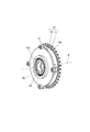
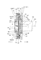
- FIG. 2 is an external perspective view in which the electric motor and the camshaft are omitted in the valve timing changing device shown in FIG. 1.
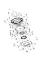
- FIG. 5 is an exploded perspective view showing a first face gear and a second face gear constituting a phase changing unit included in the apparatus shown in FIGS. 1 to 4. It is the disassembled perspective view which looked at the phase change unit shown in FIG. 5 from back diagonally.
- FIG. 5 is an exploded perspective view showing a first face gear and a second face gear constituting a phase changing unit included in the apparatus shown in FIGS. 1 to 4.
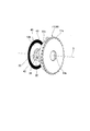
- FIG. 3 is a perspective view showing a relationship among a first face gear, a second face gear, and a pressing portion (rolling element) of a rotation adjusting member included in the phase change unit shown in FIG. 2.
- FIG. 3 is a side view showing a relationship among a first face gear, a second face gear, and a pressing portion (rolling element) of a rotation adjusting member included in the phase change unit shown in FIG. 2.
- FIG. 3 is a side view showing a relationship among a first face gear, a second face gear, and a pressing portion (rolling element) of a rotation adjusting member included in the phase change unit shown in FIG. 2. It is a disassembled perspective view which shows the valve timing change apparatus which employ
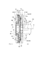
- FIG. 12 It is sectional drawing of the valve timing change apparatus shown in FIG. It is a disassembled perspective view which shows the 1st face gear and 2nd face gear which comprise the phase change unit contained in the apparatus shown in FIG.10 and FIG.11. It is the disassembled perspective view which looked at the phase change unit shown in FIG. 12 from back diagonally.
- the valve timing changing device includes a phase changing unit U as an embodiment for changing the relative rotational phase of the camshaft CS and the sprocket 11a.
- the sprocket 11a forms a part of the first rotating body that rotates in one direction around the axis S (the CR direction in FIG. 1), and interlocks with the rotation of the crankshaft via the chain.
- the camshaft CS forms a second rotating body that rotates in one direction around the axis S (the CR direction in FIG. 1).
- the phase change unit U is appropriately driven and controlled by the electric motor DM, so that the opening / closing timing (valve timing) of the intake valve or the exhaust valve driven by the camshaft CS is changed.
- the phase changing unit U includes a housing rotor 10 as a first rotating body, a first face gear 20 that rotates integrally with the housing rotor 10, and a camshaft CS as a second rotating body. , A second face gear 40 that rotates integrally with the camshaft CS via the spacer member 30, and a rotation adjustment member 50.
- the housing rotor 10 includes a first housing rotor 11 that is rotatably supported around the axis S, and a second housing rotor 12 that is connected to the first housing rotor 11 by a bolt b1.
- the first housing rotor 11 includes a sprocket 11 a, an annular inner peripheral portion 11 b into which the bearing portion 32 of the spacer member 30 is fitted, and a fixing portion 11 c that fixes the back surface of the first face gear 20.
- the regulated portion 11d, the cylindrical portion 11e, and a plurality of screw holes 11f into which the bolt b1 is screwed are provided on the outer periphery of the cylindrical portion 11e.
- the inner peripheral portion 11b is formed to have an inner diameter dimension that allows the bearing portion 32 of the spacer member 30 to be slidably fitted.
- the fixing part 11 c is formed so as to fix the fixing part 23 of the first face gear 20.
- the fixing part 11c for example, when the fixing part 23 has a concave part, it may be formed as a convex part fitted into the concave part, or may be a screwing structure or the like.
- the regulated portion 11d is formed as a stepped portion having a fanned inner wall so that the regulating portion 36 of the spacer member 30 is detachably contacted in the rotational direction around the axis S.
- the second housing rotor 12 includes an annular portion 12 a joined to the cylindrical portion 11 e of the first housing rotor 11, an annular inner peripheral portion 12 b into which the bearing RB is fitted, and an end portion of the rotation adjusting member 50. 12c and a plurality of circular holes 12d through which bolts b1 are passed.
- the opening 12c is formed in a circular shape so as to expose the connecting portion 54 of the rotation adjusting member 50.
- the inner peripheral portion 12b functions as a bearing portion that supports the rotation adjusting member 50 so as to be rotatable around the axis S via the bearing RB.
- the first housing rotor 11 is supported by the spacer member 30 so as to be rotatable around the axis S of the camshaft CS, and accommodates the first face gear 20, the second face gear 40, the rotation adjusting member 50 and the like.
- the second housing rotor 12 is connected to the first housing rotor 11 to constitute the housing rotor 10 as the first rotating body that rotates around the axis S.
- the housing rotor 10 includes the first housing rotor 11 and the second housing rotor 12, the first face gear 20, the second face gear 40, the rotation adjusting member 50, and the like are incorporated into the second housing rotor 12.
- the phase change unit U can be easily assembled.
- the first face gear 20 includes an annular flat plate portion 21, a tooth row 22 formed on the annular flat plate portion 21, and a fixing portion 23.
- the tooth row 22 has a number of teeth Z1 and is formed in an annular arrangement on the surface facing the front F in the axis S direction.
- the tooth row 22 is formed in a conical shape centered on the axis S and having a predetermined inclination angle ⁇ with respect to the axis S.
- the first face gear 20 is formed to have a tooth row shape similar to a bevel gear.
- the inclination angle ⁇ is formed so as to coincide with the inclination angle of the tooth row 43 of the second face gear 40 elastically deformed by the pressing portion 53 of the rotation adjusting member 50.
- the face gear is a gear having teeth arranged in an annular shape in a plane perpendicular to the rotation axis (axis S), and a conical surface having a predetermined inclination angle ⁇ with respect to the rotation axis as described above. It is a concept including a gear having teeth arranged in a ring shape.
- the fixing portion 23 is formed to fix the first face gear 20 to the fixing portion 11 c of the first housing rotor 11.
- the fixing portion 23 for example, when the fixing portion 11c has a convex portion, it may be formed as a concave portion into which the convex portion is fitted, or may be a screwing structure or the like. That is, the first face gear 20 is fixed to the first housing rotor 11 via the fixing portion 23 and is rotated integrally with the housing rotor 10 around the axis S.
- the spacer member 30 includes a center hole 31, a bearing portion 32, a joint surface 33, an end surface 34, an annular flange portion 35, and two restricting portions 36 that project from the annular flange portion 35 in the radial direction.
- the center hole 31 is formed to have an inner diameter through which the fastening bolt B is passed.
- the bearing portion 32 is fitted into the inner peripheral portion 11b of the first housing rotor 11 and is formed as a cylindrical surface so as to support the housing rotor 10 so as to be rotatable about the axis S.
- the joining surface 33 is formed so as to be joined to the end surface of the camshaft CS.
- the joint surface 33 may be provided with a fitting hole (not shown) for fitting a positioning pin (not shown) of the camshaft CS.
- the end face 34 is formed to project in an annular shape so that the central area of the disc portion 42 of the second face gear 40 abuts and the second face gear 40 is clamped in cooperation with the fastening bolt B.
- the annular flange 35 is formed so as to restrict the movement of the first housing rotor 11 in the direction of the axis S in cooperation with the end surface of the camshaft CS.
- the restricting portion 36 is formed so as to come into contact with the restricted portion 11 d of the first housing rotor 11 so as to be detachable in the rotational direction around the axis S. That is, the regulated portion 11d of the housing rotor 10 abuts on the regulating portion 36 of the spacer member 30 in the rotational direction around the axis S, so that the rotational phase of the housing rotor 10 in one direction and the other direction with respect to the camshaft CS is increased.
- the scope of change is regulated.
- the second face gear 40 can be connected to the camshaft CS via the spacer member 30, and the housing rotor 10 is rotated about the axis S via the spacer member 30. It can be rotatably supported. That is, since the spacer member 30 can be freely attached to and detached from the camshaft CS, the phase change unit U can be used for various engine valve timings only by making the spacer member 30 correspond to individual camshafts CS having different specifications. It can be applied to a change device. Further, the housing rotor 10 and the camshaft CS can be aligned with the spacer member 30 as a reference.
- the second face gear 40 is formed of a thin plate material that can be elastically deformed as a whole, for example, a spring steel plate or other elastic material having a thickness of 1 millimeter or less or several millimeters.
- the second face gear 40 includes a center hole 41 through which the fastening bolt B is passed, a disk part 42 forming a front surface 42a and a back surface 42b, and a tooth row 43 formed on the back surface 42b of the disk part 42.
- the tooth row 43 has a number of teeth Z2 different from the number of teeth Z1 of the first face gear 20, and is formed in an annular arrangement in the outer edge region of the back surface 42b facing the rear R in the axis S direction.
- the tooth row 43 is formed by press molding or cutting the disc portion 42.
- the second face gear 40 has a central region of the back surface 42 b of the disk portion 42 abutted against the end surface 34 of the spacer member 30, and passes the fastening bolt B through the center holes 41 and 31.
- the camshaft CS is assembled so as to rotate integrally.
- the two pressing portions 53 of the rotation adjusting member 50 are pressed in the outer edge region of the front surface 42a of the disc portion 42 and are orthogonal to the axis S. It is pressed and elastically deformed at two places aligned on a straight line, and a part of the tooth row 43 in these areas is engaged with the tooth row 22 of the first face gear 20.
- the rotation adjusting member 50 includes a cylindrical portion 51 centered on the axis S, two arm portions 52 extending radially from the cylindrical portion 51, two pressing portions 53 provided on the distal end side of the arm portion 52, and the cylindrical portion 51. And a slit-shaped connecting portion 54 formed in the above.
- the cylindrical portion 51 is formed to have an inner diameter dimension through which the fastening bolt B can be inserted. Moreover, the outer peripheral surface 51a of the cylindrical part 51 is formed so as to be rotatably supported by the second housing rotor 12 via a bearing RB. Each arm portion 52 extends in a direction of a straight line L that forms an inclination angle ⁇ with respect to the axis S so that the pressing portion 53 elastically deforms the second face gear 40 by an angle ⁇ in the assembled state. Is formed.
- Each pressing portion 53 includes a rolling element 53 a attached to an attachment hole 52 a formed on the distal end side of the arm portion 52.
- the rolling element 53 a rolls while pressing and elastically deforming the front face 42 a of the second face gear 40.
- the rolling element 53a a ball bearing including an inner ring and an outer ring, a roller rotatably supported by a support shaft in the mounting hole 52a, a sphere that is rotatably fitted in the mounting hole 52a, and other various forms.
- the eggplant can be adopted.
- the connecting portion 54 is formed in a slit shape in which the cylindrical portion 51 is cut out so that a drive shaft (not shown) of the electric motor DM exerting a rotational driving force as an external force is detachably connected.
- the two pressing portions 53 press and elastically deform the two portions of the second face gear 40, and the tooth row 43 in those regions. Is engaged with the tooth row 22 of the first face gear 20.
- the rotation adjusting member 50 is continuously moved in the meshing region of the second face gear 40 by being rotated in one direction or the other direction around the axis S by the driving force of the electric motor DM. .
- the second face gear 40 is pressed and elastically deformed at two locations by the two pressing portions 53, and the meshing area with the first face gear 20 is two locations at equal intervals in the circumferential direction around the axis S. Therefore, a balance around the axis S is secured, and a smooth rotation operation is obtained.
- the roller 53a of the pressing portion 53 elastically deforms the second face gear 40 while rolling with the rotation of the rotation adjusting member 50, the meshing region can be smoothly moved while suppressing frictional resistance and the like. Can do.
- the meshing of the face gears of the first face gear 20 and the second face gear 40 having the above configuration is mirror-symmetric with the center of meshing as a symmetry plane, backlash can be suppressed.
- the number of teeth Z1 of the first face gear 20 and the number of teeth Z2 of the second face gear 40 are appropriately selected, so that the second rotating body (camshaft CS) with respect to the first rotating body (housing rotor 10). ) Can be decelerated or increased.
- the phase change unit U functions as a speed reducer.
- the rotation of the second face gear 40 can be reduced to 1/50 with respect to one rotation of the rotation adjusting member 50. Therefore, a large reduction ratio can be obtained and the reduction ratio can be easily set only by appropriately setting the number of teeth Z1 of the first face gear 20 and the number of teeth Z2 of the second face gear 40.
- the electric motor DM when using the electric motor DM as an external force, the electric motor DM can be reduced in size.
- phase change unit U When the phase is not changed, that is, when the valve timing is not changed, no rotation driving force is exerted on the rotation adjusting member 50. Therefore, the first face gear 20 and the second face gear 40 are locked at a position where they are engaged with each other. As a result, the camshaft CS and the housing rotor 10 rotate integrally in one direction (the CR direction in FIG. 1, that is, the CW direction) around the axis S.
- a rotation driving force is exerted on the rotation adjusting member 50 by the electric motor DM.
- the rotation adjusting member 50 is rotated in one direction around the axis S (CW direction in FIG. 1), the second face gear 40 and the camshaft CS are moved relative to the first face gear 20 and the housing rotor 10. , Relatively rotate in the other direction (CCW direction in FIG. 1).
- the rotation adjusting member 50 when the rotation adjusting member 50 is continuously rotated in one direction (CW direction) a plurality of times, the rotational phase of the camshaft CS is delayed with respect to the housing rotor 10, and the intake valve or the exhaust valve The opening / closing timing of is changed to the retard side.
- phase change unit U since the meshing structure of the face gears is adopted, the structure is simplified, the number of parts is reduced, the apparatus is downsized, and the like.
- the phase can be easily changed.
- a thin plate-like second face gear 40 that can be elastically deformed so that the meshing area with the first face gear 20 can be continuously changed is adopted.
- the dimension in the axis S direction can be reduced.
- the reduction ratio can be increased, and therefore the relative rotational phase between the housing rotor 10 and the camshaft CS can be easily changed by using an external force such as a small output electric motor DM.
- the first face gear 20 is formed separately from the first housing rotor 11 and then fixed.
- the present invention is not limited to this, and the first face gear is the first face gear. It may be integrally formed with the housing rotor.
- the configuration in which the bearing portion 32 of the spacer member 30 is directly fitted into the inner peripheral portion 11b of the first housing rotor 11 and rotatably supported is shown, but is not limited thereto.
- a bearing similar to the bearing RB may be interposed between the two.
- valve timing changing apparatus including a phase changing unit U ′ according to another embodiment.
- the spacer member 30 described above is eliminated, the first face gear 20 ′ is connected to the camshaft CS, and the elastically deformable second face gear 40 ′ is connected to the housing rotor 10 ′.
- This is the same as the previous embodiment. Therefore, about the same structure, the same code
- the phase changing unit U ′ includes a housing rotor 10 ′ as a first rotating body, a first face gear 20 ′ that rotates integrally with a camshaft CS as a second rotating body, A second face gear 40 ′ that rotates integrally with the housing rotor 10 ′ and a rotation adjusting member 50 are provided.
- the housing rotor 10 ' includes a first housing rotor 11' and a second housing rotor 12 connected to the first housing rotor 11 'by a bolt b1.
- the first housing rotor 11 ′ is a plurality of members for engaging the sprocket 11 a, the annular inner peripheral portion 11 b ′ into which the bearing portion 24 ′ of the first face gear 20 ′ is fitted, and the engaging piece 44 ′ of the second face gear 40 ′.
- the inner peripheral portion 11b ' is formed to have an inner diameter dimension that fits the bearing RB' fitted to the bearing portion 24 'of the first face gear 20'.
- a plurality of latching recesses 11c ′ are formed in the circumferential direction on the inner peripheral wall of the cylindrical portion 11e. The plurality of latching recesses 11c ′ receive and latch the plurality of latching pieces 44 ′ of the second face gear 40 ′, thereby rotating the second face gear 40 ′ integrally with the housing rotor 10 ′. It is formed to let you.
- the first face gear 20 ′ includes an annular flat plate portion 21, a tooth row 22 formed on the annular flat plate portion 21, a fitting concave portion 23 ′ into which the camshaft CS is fitted, a cylindrical bearing portion 24 ′, a fastening bolt B Is provided with a central hole 25 '.
- the tooth row 22 has a number of teeth Z1 and is formed in an annular arrangement on the surface facing the front F in the axis S direction.
- the tooth row 22 is formed in a conical shape centered on the axis S and having a predetermined inclination angle ⁇ with respect to the axis S, as in the above-described embodiment. That is, the first face gear 20 'is formed to have a tooth row shape similar to a bevel gear.
- the fitting recess 23 ' is formed to have an inner diameter dimension for fitting the end of the camshaft CS.
- a fitting hole 23a ′ for fitting a positioning pin (not shown) of the camshaft CS is provided on the bottom surface of the fitting recess 23 ′.
- the bearing portion 24 ′ is formed to have an outer diameter that fits the bearing RB ′.
- the second face gear 40 ' is formed into an annular flat plate by a thin plate material that can be elastically deformed as a whole, for example, a spring steel plate or other elastic material having a thickness of 1 millimeter or less or several millimeters. .
- the second face gear 40 ' includes a center hole 41', an annular disc portion 42 'forming a front surface 42a' and a rear surface 42b ', a tooth row 43 formed on the rear surface 42b' of the annular disc portion 42 ', and an annular disc.
- a plurality of retaining pieces 44 ′ projecting radially outward in the outer edge region of the portion 42 ′ are provided.
- the tooth row 43 has a number of teeth Z2 different from the number of teeth Z1 of the first face gear 20 ', and is formed in an annular arrangement in the outer edge region of the back surface 42b' facing the rear R in the axis S direction.
- the tooth row 43 is formed by press-molding or cutting the annular disk portion 42 ′.
- the second face gear 40 ′ is disposed in the first housing rotor 11 ′, and the plurality of latching pieces 44 ′ are latched by the plurality of latching recesses 11 c ′.
- the second face gear 40 ′ is pressed and elastically pressed at two places aligned on a straight line perpendicular to the axis S with the two pressing portions 53 of the rotation adjusting member 50 being pressed in the state of being incorporated as described above. It is deformed, and a part of the tooth row 43 in those regions is meshed with the tooth row 22 of the first face gear 20 ′.
- the second face gear 40 ′ is held in a non-contact state with the pressing portion 53 and the first face gear 20 ′ in other areas except the pressing area by the pressing section 53 and the meshing area.
- the first face gear 20 ' is detachably attached to the camshaft CS and rotatably supports the housing rotor 10'. Therefore, the first face gear 20 'is supported by each camshaft CS. It is possible to apply the phase changing unit U ′ to various camshafts CS simply by making it correspond. Further, the housing rotor 10 ′ and the camshaft CS can be aligned with the first face gear 20 ′ as a reference.
- the second face gear 40 ' has a plurality of latching pieces 44' in the outer edge region and the housing rotor 10 'has a plurality of latching recesses 11c' on the inner peripheral wall thereof
- the second face gear 40 ' By simply fitting the latching piece 44 'into the latching recess 11c' of the housing rotor 10 'and latching it, the second face gear 40' can be rotated integrally with the housing rotor 10 '. Can be assembled.
- the face gear meshing structure is adopted as in the above-described embodiment, so that the structure is simplified, the number of parts is reduced, and the apparatus is downsized.
- the phase can be easily changed.
- a thin plate-like second face gear 40 ′ that is elastically deformable so that the meshing area with the first face gear 20 ′ can be continuously changed is adopted as one face gear that forms a meshing structure between the face gears. Therefore, the dimension in the axis S direction can be reduced.
- the reduction ratio can be increased, so that the relative rotational phase between the housing rotor 10 ′ and the camshaft CS can be easily changed using an external force such as a small output electric motor DM. it can.
- phase change unit U ′ When the phase is not changed, that is, when the valve timing is not changed, no rotation driving force is exerted on the rotation adjusting member 50. Accordingly, the first face gear 20 'and the second face gear 40' are locked at the positions where they are engaged with each other. Thereby, the camshaft CS and the housing rotor 10 ′ are integrally rotated around the axis S in one direction (the CR direction in FIG. 1, that is, the CW direction).
- the phase is changed, that is, when the valve timing is changed, a rotation driving force is exerted on the rotation adjusting member 50 by the electric motor DM.
- the rotation adjusting member 50 is rotated in one direction around the axis S (CW direction in FIG. 1)
- the second face gear 40 'and the housing rotor 10' are moved to the first face gear 20 'and the camshaft CS.
- it rotates in the other direction (CCW direction in FIG. 1) relatively. Therefore, when the rotation adjusting member 50 is continuously rotated in one direction (CW direction) a plurality of times, the rotational phase of the camshaft CS is advanced with respect to the housing rotor 10 ', and the intake valve or the exhaust gas is exhausted. The opening / closing timing of the valve is changed to the advance side.
- the rotation adjusting member 50 when the rotation adjusting member 50 is rotated in the other direction around the axis S (CCW direction in FIG. 1), the second face gear 40 'and the housing rotor 10' are moved to the first face gear 20 'and the camshaft CS. Rotate relatively in one direction (CW direction in FIG. 1). Accordingly, when the rotation adjusting member 50 is continuously rotated in the other direction (CCW direction) a plurality of times, the rotational phase of the camshaft CS is delayed with respect to the housing rotor 10 ', and the intake valve or the exhaust gas is exhausted. The opening / closing timing of the valve is changed to the retard side. That is, when the rotation adjustment member 50 is rotated in one direction (CW direction in FIG. 1), an advance operation is performed, and when the rotation adjustment member 50 is rotated in the other direction (CCW direction in FIG. 1), a retard operation is performed. Is done.
- phase change unit U ′ configured as described above, since the meshing structure of the face gears is adopted, the structure is simplified, the number of parts is reduced, and the apparatus is downsized.
- the phase can be easily changed.
- a thin plate-like second face gear 40 ′ that is elastically deformable so that the meshing area with the first face gear 20 ′ can be continuously changed is adopted as one face gear that forms a meshing structure between the face gears. Therefore, the dimension in the axis S direction can be reduced.
- the reduction ratio can be increased, so that the relative rotational phase between the housing rotor 10 ′ and the camshaft CS can be easily changed using an external force such as a small output electric motor DM. it can.
- the present invention is not limited to this. However, as long as the relative rotation can be regulated, one latching piece and one latching recess may be employed, or another regulating means may be employed.
- the present invention is not limited to this, and one pressing portion or three pressing portions are used. You may employ
- the present invention is not limited to this. It is not a thing and can be suitably selected in the range which satisfies the above formula.
- the tooth rows 22 of the first face gears 20 and 20 ′ are formed in a conical shape with the axis S as the center is shown, but the present invention is not limited to this.
- the tooth row of the first face gear may be formed on a surface perpendicular to the axis S, and the tooth row of the second face gear may be formed in a conical shape with the axis as the center.
- phase change units U and U ′ as speed reducers applied to the valve timing change device are shown as the phase change unit.
- the present invention is not limited to this. It can also be applied as a speed reducer or a transmission in a mechanism or device that needs to change the relative rotational phase of the motor.
- CS camshaft (second rotating body) S axis RB, RB 'bearing (radial bearing) 10, 10 'housing rotor (first rotating body) 11, 11 'first housing rotor 11c' latching recess 11d regulated portion 12 second housing rotor 20, 20 'first face gear 22 tooth row 23' fitting recess 24 'bearing portion 30 spacer member 32 bearing portion 36 regulation Part 40, 40 'second face gear 41, 41' center hole 43 tooth row 44 'latching piece 50 rotation adjusting member 53 pressing part 53a rolling element
Landscapes
- Engineering & Computer Science (AREA)
- Mechanical Engineering (AREA)
- General Engineering & Computer Science (AREA)
- Valve Device For Special Equipments (AREA)
Abstract
本発明の位相変更ユニットは、第1回転体及び第2回転体の一方と一体的に回転する第1フェースギヤ(20)、第1回転体及び第2回転体の他方と一体的に回転すると共に第1フェースギヤと異なる歯数を有しかつ弾性変形可能な薄板状の第2フェースギヤ(40)、第2フェースギヤを弾性変形させてその歯列(43)の一部を第1フェースギヤに噛合させると共に第2フェースギヤの噛合領域を移動させるべく外力により軸線(S)回りに回転調整される回転調整部材(50)を含む。これによれば、構造の簡素化、部品点数の削減、装置の小型化、位相変更の容易化等を達成できる。
Description
本発明は、二つの回転体の回転位相を変更する位相変更ユニットに関し、特に、内燃エンジンの吸気バルブ又は排気バルブの開閉時期(バルブタイミング)を変更する際に適用される位相変更ユニット及びそれを用いたバルブタイミング変更装置に関する。
従来のバルブタイミング変更装置としては、カムシャフトの中心軸線周りに回転するスプロケット及び内歯車、中心軸線に対して偏心する偏心軸、偏心軸の回りに回動自在に支持されると共に内歯車に噛合する遊星歯車、カムシャフトに連結されると共に遊星歯車に係合することで遊星歯車の回転に伴いカムシャフトと一体的に回転する出力軸、偏心軸に連結される作用軸、作用軸にトルクを付与する電磁部等を備えたものが知られている(例えば、特許文献1を参照)。
上記バルブタイミング変更装置においては、スプロケットとカムシャフトとの相対的な回転位相を変更する位相変更ユニットとして、サイクロ減速機構である内接式遊星歯車機構を採用するものである。
しかしながら、このような内接式遊星歯車機構では、内歯車の径方向内側に遊星歯車を配置するため、径方向の小型化等を図るには限界があり、又、高減速比の要求と小型化の要求を両立させるのは困難である。
しかしながら、このような内接式遊星歯車機構では、内歯車の径方向内側に遊星歯車を配置するため、径方向の小型化等を図るには限界があり、又、高減速比の要求と小型化の要求を両立させるのは困難である。
本発明は、上記の事情に鑑みて成されたものであり、その目的とするところは、上記従来技術の問題点等を解消して、小さい出力の電動モータ等の外力を用いて二つの回転体の回転位相を容易に変更できる、位相変更ユニット及びそれを用いたバルブタイミング変更装置を提供することにある。
本発明の位相変更ユニットは、所定の軸線回りに回転する第1回転体及び第2回転体の相対的な回転位相を変更する位相変更ユニットであって、上記第1回転体及び第2回転体の一方と一体的に回転する第1フェースギヤと、上記第1回転体及び第2回転体の他方と一体的に回転すると共に第1フェースギヤの歯数とは異なる歯数を有しかつ弾性変形可能な薄板状の第2フェースギヤと、第2フェースギヤを弾性変形させてその歯列の一部を第1フェースギヤに噛合させると共に第2フェースギヤの噛合領域を移動させるべく,外力により上記軸線回りに回転調整される回転調整部材を含む、構成となっている。
上記構成をなす位相変更ユニットにおいて、第1フェースギヤの歯列及び第2フェースギヤの歯列の一方は、上記軸線を中心とする円錐状に形成されている、構成を採用してもよい。
上記構成をなす位相変更ユニットにおいて、回転調整部材は、第2フェースギヤを複数箇所において押圧して弾性変形させる複数の押圧部を含む、構成を採用してもよい。
上記構成をなす位相変更ユニットにおいて、押圧部は、第2フェースギヤに接触しつつ転動する転動体を含む、構成を採用してもよい。
上記構成をなす位相変更ユニットにおいて、第1回転体は、第1フェースギヤ、第2フェースギヤ、及び回転調整部材を収容するハウジングロータを含み、第1フェースギヤは、ハウジングロータと一体的に回転するように連結され、第2フェースギヤは、第2回転体と一体的に回転するように連結され、回転調整部材は、ハウジングロータに対して回動自在に支持されている、構成を採用してもよい。
上記構成をなす位相変更ユニットにおいて、第2フェースギヤは、スペーサ部材を介して第2回転体に連結され、スペーサ部材は、ハウジングロータを回動自在に支持する軸受部を有する、構成を採用してもよい。
上記構成をなす位相変更ユニットにおいて、スペーサ部材は、第1回転体と第2回転体との相対的な回転範囲を規制する規制部を有し、ハウジングロータは、規制部が当接する被規制部を有する、構成を採用してもよい。
上記構成をなす位相変更ユニットにおいて、ハウジングロータは、第1フェースギヤが配置された第1ハウジングロータと、第1ハウジングロータに連結される第2ハウジングロータを含み、第2ハウジングロータは、回転調整部材を上記軸線回りに回動自在に支持する軸受部を有する、構成を採用してもよい。
また、上記構成をなす位相変更ユニットにおいて、第1回転体は、第1フェースギヤ、第2フェースギヤ、及び回転調整部材を収容するハウジングロータを含み、第1フェースギヤは、第2回転体と一体的に回転するように連結され、第2フェースギヤは、第1回転体と一体的に回転するように連結され、回転調整部材は、ハウジングロータに対して回動自在に支持されている、構成を採用してもよい。
上記構成をなす位相変更ユニットにおいて、第1フェースギヤは、ハウジングロータを回動自在に支持する軸受部を有する、構成を採用してもよい。
上記構成をなす位相変更ユニットにおいて、第2フェースギヤは、その外縁領域において掛止片を有し、ハウジングロータは、その内周壁において掛止片を掛止する掛止凹部を有する、構成を採用してもよい。
上記構成をなす位相変更ユニットにおいて、ハウジングロータは、第2フェースギヤを一体的に回転するように連結する第1ハウジングロータと、第1ハウジングロータに連結される第2ハウジングロータを含み、第2ハウジングロータは、回転調整部材を上記軸線回りに回動自在に支持する軸受部を有する、構成を採用してもよい。
本発明のバルブタイミング変更装置は、第1回転体をなすハウジングロータと第2回転体をなすカムシャフトの相対的な回転位相を変更する位相変更ユニットを備え、カムシャフトにより駆動される吸気バルブ又は排気バルブの開閉時期を変更するバルブタイミング変更装置であって、位相変更ユニットとして、上記構成をなすいずれかの位相変更ユニットを採用するものである。
上記構成をなす位相変更ユニットによれば、構造の簡素化、部品点数の削減、装置の小型化等を達成しつつ、位相を容易に変更することができる。例えば、減速機として用いる場合に減速比を大きくすることができる。それ故に、小さい出力の電動モータ等の外力を用いて二つの回転体の回転位相を容易に変更できる。例えば、エンジンのバルブタイミング変更装置に適用することにより、装置の小型化、薄型化等を達成しつつ、バルブタイミングを容易に変更できる。
以下、本発明の実施形態について、添付図面を参照しつつ説明する。
この実施形態に係るバルブタイミング変更装置は、図1に示すように、カムシャフトCSとスプロケット11aの相対的な回転位相を変更する一実施形態としての位相変更ユニットUを備えている。
ここで、スプロケット11aは、軸線S回りの一方向(図1中のCR方向)に回転する第1回転体の一部を形成し、チェーンを介してクランクシャフトの回転に連動する。
カムシャフトCSは、軸線S回りの一方向(図1中のCR方向)に回転する第2回転体を形成する。
この実施形態に係るバルブタイミング変更装置は、図1に示すように、カムシャフトCSとスプロケット11aの相対的な回転位相を変更する一実施形態としての位相変更ユニットUを備えている。
ここで、スプロケット11aは、軸線S回りの一方向(図1中のCR方向)に回転する第1回転体の一部を形成し、チェーンを介してクランクシャフトの回転に連動する。
カムシャフトCSは、軸線S回りの一方向(図1中のCR方向)に回転する第2回転体を形成する。
そして、位相変更ユニットUが、電動モータDMにより適宜駆動制御されることにより、カムシャフトCSにより駆動される吸気バルブ又は排気バルブの開閉時期(バルブタイミング)が変更されるようになっている。
位相変更ユニットUは、図1ないし図9に示すように、第1回転体としてのハウジングロータ10、ハウジングロータ10と一体的に回転する第1フェースギヤ20、第2回転体としてのカムシャフトCSに連結されるスペーサ部材30、スペーサ部材30を介してカムシャフトCSと一体的に回転する第2フェースギヤ40、回転調整部材50を備えている。
ハウジングロータ10は、軸線S回りに回動自在に支持される第1ハウジングロータ11、第1ハウジングロータ11に対してボルトb1により連結される第2ハウジングロータ12を備えている。
第1ハウジングロータ11は、図3ないし図5に示すように、スプロケット11a、スペーサ部材30の軸受部32を嵌め込む環状の内周部11b、第1フェースギヤ20の背面を固定する固定部11c、被規制部11d、円筒部11e、円筒部11eの外周においてボルトb1を捩じ込む複数のネジ孔11fを備えている。
内周部11bは、スペーサ部材30の軸受部32を摺動自在に嵌合する内径寸法に形成されている。
固定部11cは、第1フェースギヤ20の固定部23を固定するように形成されている。固定部11cとしては、例えば、固定部23が凹部を有する場合に、その凹部に嵌め込まれる凸部として形成されてもよく、その他、ネジ止め構造等であってもよい。
被規制部11dは、スペーサ部材30の規制部36を軸線S回りの回転方向において離脱可能に当接させるべく、内壁を扇状に肉抜きされた段差部として形成されている。
固定部11cは、第1フェースギヤ20の固定部23を固定するように形成されている。固定部11cとしては、例えば、固定部23が凹部を有する場合に、その凹部に嵌め込まれる凸部として形成されてもよく、その他、ネジ止め構造等であってもよい。
被規制部11dは、スペーサ部材30の規制部36を軸線S回りの回転方向において離脱可能に当接させるべく、内壁を扇状に肉抜きされた段差部として形成されている。
第2ハウジングロータ12は、図4に示すように、第1ハウジングロータ11の円筒部11eに接合される環状部12a、軸受RBを嵌め込む環状の内周部12b、回転調整部材50の端部を露出させる開口部12c、ボルトb1を通す複数の円孔12dを備えている。
開口部12cは、回転調整部材50の連結部54を露出させるように円形に形成されている。
内周部12bは、軸受RBを介して回転調整部材50を軸線S回りに回動自在に支持する軸受部として機能する。
開口部12cは、回転調整部材50の連結部54を露出させるように円形に形成されている。
内周部12bは、軸受RBを介して回転調整部材50を軸線S回りに回動自在に支持する軸受部として機能する。
そして、第1ハウジングロータ11がスペーサ部材30を介してカムシャフトCSの軸線S回りに回動自在に支持され、第1フェースギヤ20、第2フェースギヤ40、回転調整部材50等を収容した状態で、第2ハウジングロータ12が第1ハウジングロータ11に連結されることにより、軸線S回りに回転する第1回転体としてのハウジングロータ10が構成される。
このように、ハウジングロータ10が、第1ハウジングロータ11と第2ハウジングロータ12を含むため、第1フェースギヤ20、第2フェースギヤ40、回転調整部材50等を組み込んで、第2ハウジングロータ12を第1ハウジングロータ11に連結することにより、位相変更ユニットUを容易に組み立てることができる。
第1フェースギヤ20は、環状平板部21、環状平板部21に形成された歯列22、固定部23を備えている。
歯列22は、歯数Z1からなり、軸線S方向の前方Fを向く面において環状に配列して形成されている。
ここで、歯列22は、図9に示すように、軸線Sを中心とすると共に軸線Sに対して所定の傾斜角度θをなす円錐状に形成されている。すなわち、第1フェースギヤ20は、かさ歯車と同様の歯列形状を有するように形成されている。
歯列22は、歯数Z1からなり、軸線S方向の前方Fを向く面において環状に配列して形成されている。
ここで、歯列22は、図9に示すように、軸線Sを中心とすると共に軸線Sに対して所定の傾斜角度θをなす円錐状に形成されている。すなわち、第1フェースギヤ20は、かさ歯車と同様の歯列形状を有するように形成されている。
傾斜角度θは、回転調整部材50の押圧部53により弾性変形させられた第2フェースギヤ40の歯列43の傾斜角度と一致するように形成されている。
これにより、第2フェースギヤ40の歯列43の一部が第1フェースギヤ20の歯列22に噛合う際に、歯筋に沿った全域を噛合わせることができる。
それ故に、確実な噛合関係が得られ、歯飛び等の現象を防止でき、確実なトルク伝達を得ることができる。
これにより、第2フェースギヤ40の歯列43の一部が第1フェースギヤ20の歯列22に噛合う際に、歯筋に沿った全域を噛合わせることができる。
それ故に、確実な噛合関係が得られ、歯飛び等の現象を防止でき、確実なトルク伝達を得ることができる。
尚、本発明において、フェースギヤとは、回転軸線(軸線S)に垂直な面において環状に配列された歯列を有する歯車、上述の如く回転軸線に対して所定の傾斜角度θをなす円錐面おいて環状に配列された歯列を有する歯車等を含む概念である。
固定部23は、第1ハウジングロータ11の固定部11cに対して、第1フェースギヤ20を固定するように形成されている。固定部23としては、例えば、固定部11cが凸部を有する場合に、その凸部を嵌め込む凹部として形成されてもよく、その他、ネジ止め構造等であってもよい。
すなわち、第1フェースギヤ20は、固定部23を介して第1ハウジングロータ11に固定され、軸線S回りにおいてハウジングロータ10と一体的に回転するようになっている。
すなわち、第1フェースギヤ20は、固定部23を介して第1ハウジングロータ11に固定され、軸線S回りにおいてハウジングロータ10と一体的に回転するようになっている。
スペーサ部材30は、中心孔31、軸受部32、接合面33、端面34、環状鍔部35、環状鍔部35から径方向に突出する二つの規制部36を備えている。
中心孔31は、締結ボルトBを通す内径寸法に形成されている。
軸受部32は、第1ハウジングロータ11の内周部11bに嵌め込まれて、ハウジングロータ10を軸線S回りに回動自在に支持するように円筒面として形成されている。
接合面33は、カムシャフトCSの端面に接合されるように形成されている。
尚、接合面33には、カムシャフトCSの位置決めピン(不図示)を嵌め込む嵌合穴(不図示)が設けられていてもよい。
軸受部32は、第1ハウジングロータ11の内周部11bに嵌め込まれて、ハウジングロータ10を軸線S回りに回動自在に支持するように円筒面として形成されている。
接合面33は、カムシャフトCSの端面に接合されるように形成されている。
尚、接合面33には、カムシャフトCSの位置決めピン(不図示)を嵌め込む嵌合穴(不図示)が設けられていてもよい。
端面34は、第2フェースギヤ40の円板部42の中央領域を当接させ、締結ボルトBと協働して第2フェースギヤ40を挟持するように、環状に突出して形成されている。
環状鍔部35は、カムシャフトCSの端面と協働して第1ハウジングロータ11が軸線S方向に移動するのを規制するように形成されている。
環状鍔部35は、カムシャフトCSの端面と協働して第1ハウジングロータ11が軸線S方向に移動するのを規制するように形成されている。
規制部36は、第1ハウジングロータ11の被規制部11dに対して、軸線S回りの回転方向に離脱可能に当接するように形成されている。
すなわち、ハウジングロータ10の被規制部11dが、軸線S回りの回転方向においてスペーサ部材30の規制部36に当接することにより、カムシャフトCSに対するハウジングロータ10の一方向及び他方向への回転位相の変更の範囲が規制されるようになっている。
すなわち、ハウジングロータ10の被規制部11dが、軸線S回りの回転方向においてスペーサ部材30の規制部36に当接することにより、カムシャフトCSに対するハウジングロータ10の一方向及び他方向への回転位相の変更の範囲が規制されるようになっている。
このように、スペーサ部材30を設けることにより、スペーサ部材30を介して第2フェースギヤ40をカムシャフトCSに連結することができ、又、スペーサ部材30を介してハウジングロータ10を軸線S回りに回動自在に支持することができる。
すなわち、スペーサ部材30をカムシャフトCSに対して着脱自在とすることができるため、スペーサ部材30を仕様の異なる個々のカムシャフトCSに対応させるだけで、位相変更ユニットUを種々のエンジンのバルブタイミング変更装置に適用することができる。また、スペーサ部材30を基準として、ハウジングロータ10とカムシャフトCSの位置合わせを行うことができる。
すなわち、スペーサ部材30をカムシャフトCSに対して着脱自在とすることができるため、スペーサ部材30を仕様の異なる個々のカムシャフトCSに対応させるだけで、位相変更ユニットUを種々のエンジンのバルブタイミング変更装置に適用することができる。また、スペーサ部材30を基準として、ハウジングロータ10とカムシャフトCSの位置合わせを行うことができる。
第2フェースギヤ40は、全体が弾性変形可能な薄板状の材料、例えば、1ミリメートル以下あるいは数ミリメートル程度の厚さをなすバネ鋼板あるいはその他の弾性材料等により形成されている。
第2フェースギヤ40は、締結ボルトBを通す中心孔41、前面42a及び背面42bをなす円板部42、円板部42の背面42bに形成された歯列43を備えている。
歯列43は、第1フェースギヤ20の歯数Z1と異なる歯数Z2からなり、軸線S方向の後方Rを向く背面42bの外縁領域において環状に配列して形成されている。尚、歯列43は、円板部42をプレス成型あるいは切削することにより形成されている。
第2フェースギヤ40は、締結ボルトBを通す中心孔41、前面42a及び背面42bをなす円板部42、円板部42の背面42bに形成された歯列43を備えている。
歯列43は、第1フェースギヤ20の歯数Z1と異なる歯数Z2からなり、軸線S方向の後方Rを向く背面42bの外縁領域において環状に配列して形成されている。尚、歯列43は、円板部42をプレス成型あるいは切削することにより形成されている。
そして、第2フェースギヤ40は、図4に示すように、円板部42の背面42bの中央領域がスペーサ部材30の端面34に当接され、締結ボルトBを中心孔41,31に通してカムシャフトCSのネジ穴CS1に捩じ込むことにより、カムシャフトCSと一体的に回転するように組み付けられる。
また、第2フェースギヤ40は、上記のように組み付けられた状態において、円板部42の前面42aの外縁領域において、回転調整部材50の二つの押圧部53が押し付けられ、軸線Sと直交する直線上に並ぶ二箇所において押圧されて弾性変形させられ、それらの領域における歯列43の一部が、第1フェースギヤ20の歯列22に噛合させられるようになっている。
回転調整部材50は、軸線Sを中心とする円筒部51、円筒部51から径方向に伸長する二つの腕部52、腕部52の先端側に設けられた二つの押圧部53、円筒部51に形成されたスリット状の連結部54を備えている。
円筒部51は、締結ボルトBを挿通し得る内径寸法に形成されている。また、円筒部51の外周面51aは、軸受RBを介して第2ハウジングロータ12により回動自在に支持されるように形成されている。
各々の腕部52は、組付けられた状態で、押圧部53が第2フェースギヤ40を角度θだけ弾性変形させるように、軸線Sに対して傾斜角度θをなす直線L方向に伸長するように形成されている。
各々の腕部52は、組付けられた状態で、押圧部53が第2フェースギヤ40を角度θだけ弾性変形させるように、軸線Sに対して傾斜角度θをなす直線L方向に伸長するように形成されている。
各々の押圧部53は、腕部52の先端側に形成された取付け孔52aに取り付けられた転動体53aを備えている。
転動体53aは、第2フェースギヤ40の前面42aを押圧して弾性変形させつつ転動するようになっている。
ここで、転動体53aとしては、内輪及び外輪を含むボールベアリング、取付け孔52aにおいて支軸により回動自在に支持されたローラ、取付け孔52aに転動自在に嵌め込まれた球体、その他種々の形態なすものを採用することができる。
連結部54は、外力としての回転駆動力を及ぼす電動モータDMの駆動軸(不図示)が着脱自在に連結されるべく、円筒部51を切り欠いたスリット状に形成されている。
転動体53aは、第2フェースギヤ40の前面42aを押圧して弾性変形させつつ転動するようになっている。
ここで、転動体53aとしては、内輪及び外輪を含むボールベアリング、取付け孔52aにおいて支軸により回動自在に支持されたローラ、取付け孔52aに転動自在に嵌め込まれた球体、その他種々の形態なすものを採用することができる。
連結部54は、外力としての回転駆動力を及ぼす電動モータDMの駆動軸(不図示)が着脱自在に連結されるべく、円筒部51を切り欠いたスリット状に形成されている。
したがって、回転調整部材50は、図4に示すように組み込まれた状態で、二つの押圧部53が第2フェースギヤ40の二箇所を押圧して弾性変形させて、それらの領域における歯列43の一部を第1フェースギヤ20の歯列22に噛合させる。
そして、回転調整部材50が、電動モータDMの駆動力により軸線S回りにおいて一方向又は他方向に回転させられることにより、第2フェースギヤ40の噛合領域を連続的に移動させるようになっている。
そして、回転調整部材50が、電動モータDMの駆動力により軸線S回りにおいて一方向又は他方向に回転させられることにより、第2フェースギヤ40の噛合領域を連続的に移動させるようになっている。
ここでは、二つの押圧部53により、第2フェースギヤ40を二箇所において押圧して弾性変形させて、第1フェースギヤ20との噛合領域が、軸線S回りの周方向において等間隔の二箇所に設定されているため、軸線S回りのバランスが確保され、円滑な回転動作が得られる。
また、押圧部53のローラ53aが、回転調整部材50の回転に伴って転動しつつ第2フェースギヤ40を弾性変形させるため、摩擦抵抗等を抑制しつつ、噛合領域を円滑に移動させることができる。
さらに、上記構成をなす第1フェースギヤ20と第2フェースギヤ40のフェースギヤ同士の噛合いは、噛合いの中心を対称面とした鏡面対称となるため、バックラッシを抑制することができる。
また、押圧部53のローラ53aが、回転調整部材50の回転に伴って転動しつつ第2フェースギヤ40を弾性変形させるため、摩擦抵抗等を抑制しつつ、噛合領域を円滑に移動させることができる。
さらに、上記構成をなす第1フェースギヤ20と第2フェースギヤ40のフェースギヤ同士の噛合いは、噛合いの中心を対称面とした鏡面対称となるため、バックラッシを抑制することができる。
また、第1フェースギヤ20の歯数Z1、第2フェースギヤ40の歯数Z2は、適宜選択されることにより、第1回転体(ハウジングロータ10)に対して第2回転体(カムシャフトCS)を減速させ又は増速させることができる。この装置において、位相変更ユニットUは、減速機として機能する。
ここで、上記構成をなす位相変更ユニットUにおいて、第1フェースギヤ20の歯数Z1、第2フェースギヤ40の歯数Z2の関係は、第2フェースギヤ40の噛合箇所の個数をN、正の整数をnとすると、Z2=Z1±n・Nの関係が成立するように設定される。
この実施形態においては、N=2、n=1として、Z1=102、Z2=Z1-2=100として設定されている。
この実施形態においては、N=2、n=1として、Z1=102、Z2=Z1-2=100として設定されている。
また、回転調整部材50の回転を入力、第2フェースギヤ40の回転を出力とするとき、減速比i=(Z1-Z2)/Z2=(102-100)/100=1/50となる。
これによれば、回転調整部材50の1回転に対して、第2フェースギヤ40の回転を1/50まで減速することができる。
したがって、第1フェースギヤ20の歯数Z1と第2フェースギヤ40の歯数Z2を適宜設定するだけで、大きな減速比を得ることができ、又、減速比の設定が容易である。
これにより、外力として電動モータDMを使用する場合、電動モータDMを小型化することができる。
これによれば、回転調整部材50の1回転に対して、第2フェースギヤ40の回転を1/50まで減速することができる。
したがって、第1フェースギヤ20の歯数Z1と第2フェースギヤ40の歯数Z2を適宜設定するだけで、大きな減速比を得ることができ、又、減速比の設定が容易である。
これにより、外力として電動モータDMを使用する場合、電動モータDMを小型化することができる。
次に、上記の位相変更ユニットUの動作を説明する。
先ず、位相の変更を行わない、すなわち、バルブタイミングを変更しない場合は、回転調整部材50に回転駆動力が及ぼされない。
したがって、第1フェースギヤ20と第2フェースギヤ40は、互いに噛合った位置でロックされる。
これにより、カムシャフトCSとハウジングロータ10は、軸線S回りにおいて一方向(図1中のCR方向、すなわちCW方向)に一体的に回転する。
先ず、位相の変更を行わない、すなわち、バルブタイミングを変更しない場合は、回転調整部材50に回転駆動力が及ぼされない。
したがって、第1フェースギヤ20と第2フェースギヤ40は、互いに噛合った位置でロックされる。
これにより、カムシャフトCSとハウジングロータ10は、軸線S回りにおいて一方向(図1中のCR方向、すなわちCW方向)に一体的に回転する。
一方、位相を変更する、すなわち、バルブタイミングを変更する場合は、電動モータDMにより、回転調整部材50に回転駆動力が及ぼされる。
例えば、回転調整部材50が軸線S回りの一方向(図1中のCW方向)に回転させられると、第2フェースギヤ40及びカムシャフトCSが、第1フェースギヤ20及びハウジングロータ10に対して、相対的に他方向(図1中のCCW方向)に回転する。
したがって、回転調整部材50が一方向(CW方向)に連続して複数回に亘って回転させられることにより、ハウジングロータ10に対してカムシャフトCSの回転位相が遅らせられて、吸気バルブ又は排気バルブの開閉時期が遅角側に変更される。
例えば、回転調整部材50が軸線S回りの一方向(図1中のCW方向)に回転させられると、第2フェースギヤ40及びカムシャフトCSが、第1フェースギヤ20及びハウジングロータ10に対して、相対的に他方向(図1中のCCW方向)に回転する。
したがって、回転調整部材50が一方向(CW方向)に連続して複数回に亘って回転させられることにより、ハウジングロータ10に対してカムシャフトCSの回転位相が遅らせられて、吸気バルブ又は排気バルブの開閉時期が遅角側に変更される。
一方、回転調整部材50が軸線S回りの他方向(図1中のCCW方向)に回転させられると、第2フェースギヤ40及びカムシャフトCSが、第1フェースギヤ20及びハウジングロータ10に対して、相対的に一方向(図1中のCW方向)に回転する。
したがって、回転調整部材50が他方向(CCW方向)に連続して複数回に亘って回転させられることにより、ハウジングロータ10に対してカムシャフトCSの回転位相が進められて、吸気バルブ又は排気バルブの開閉時期が進角側に変更される。
すなわち、回転調整部材50を一方向(図1中のCW方向)に回転させると遅角動作が行われ、回転調整部材50を他方向(図1中のCCW方向)に回転させると進角動作が行われる。
したがって、回転調整部材50が他方向(CCW方向)に連続して複数回に亘って回転させられることにより、ハウジングロータ10に対してカムシャフトCSの回転位相が進められて、吸気バルブ又は排気バルブの開閉時期が進角側に変更される。
すなわち、回転調整部材50を一方向(図1中のCW方向)に回転させると遅角動作が行われ、回転調整部材50を他方向(図1中のCCW方向)に回転させると進角動作が行われる。
以上述べたように、上記構成をなす位相変更ユニットUによれば、フェースギヤ同士の噛合い構造を採用するため、構造の簡素化、部品点数の削減、装置の小型化等を達成しつつ、位相を容易に変更することができる。
特に、フェースギヤ同士の噛合い構造をなす一方のフェースギヤとして、第1フェースギヤ20との噛合領域が連続的に変えられるべく弾性変形可能な薄板状の第2フェースギヤ40を採用するため、軸線S方向における寸法を小さくできる。
また、この位相変更ユニットUによれば、減速比を大きくできるため、小さい出力の電動モータDM等の外力を用いて、ハウジングロータ10とカムシャフトCSの相対的な回転位相を容易に変更できる。
特に、フェースギヤ同士の噛合い構造をなす一方のフェースギヤとして、第1フェースギヤ20との噛合領域が連続的に変えられるべく弾性変形可能な薄板状の第2フェースギヤ40を採用するため、軸線S方向における寸法を小さくできる。
また、この位相変更ユニットUによれば、減速比を大きくできるため、小さい出力の電動モータDM等の外力を用いて、ハウジングロータ10とカムシャフトCSの相対的な回転位相を容易に変更できる。
上記実施形態においては、第1フェースギヤ20が、第1ハウジングロータ11と別個に形成された後に固定される形態を示したが、これに限定されるものではなく、第1フェースギヤが第1ハウジングロータに一体成型されてもよい。
上記実施形態においては、スペーサ部材30の軸受部32が第1ハウジングロータ11の内周部11bに直接嵌め込まれて回動自在に支持する構成を示したが、これに限定されるものではなく、軸受RBと同様の軸受を両者の間に介在させてもよい。
上記実施形態においては、スペーサ部材30の軸受部32が第1ハウジングロータ11の内周部11bに直接嵌め込まれて回動自在に支持する構成を示したが、これに限定されるものではなく、軸受RBと同様の軸受を両者の間に介在させてもよい。
図10ないし図13は、他の実施形態に係る位相変更ユニットU´を備えたバルブタイミング変更装置を示すものである。
この実施形態においては、前述のスペーサ部材30を廃止し、第1フェースギヤ20´をカムシャフトCSに連結し、弾性変形可能な第2フェースギヤ40´をハウジングロータ10´に連結した以外は、前述の実施形態と同一である。したがって、同一の構成については、同一の符号を付して説明を省略する。
この実施形態においては、前述のスペーサ部材30を廃止し、第1フェースギヤ20´をカムシャフトCSに連結し、弾性変形可能な第2フェースギヤ40´をハウジングロータ10´に連結した以外は、前述の実施形態と同一である。したがって、同一の構成については、同一の符号を付して説明を省略する。
位相変更ユニットU´は、図10ないし図13に示すように、第1回転体としてのハウジングロータ10´、第2回転体としてのカムシャフトCSと一体的に回転する第1フェースギヤ20´、ハウジングロータ10´と一体的に回転する第2フェースギヤ40´、回転調整部材50を備えている。
ハウジングロータ10´は、第1ハウジングロータ11´、第1ハウジングロータ11´に対してボルトb1により連結される第2ハウジングロータ12を備えている。
第1ハウジングロータ11´は、スプロケット11a、第1フェースギヤ20´の軸受部24´を嵌め込む環状の内周部11b´、第2フェースギヤ40´の掛止片44´を掛止する複数の掛止凹部11c´、円筒部11e、円筒部11eの外周においてボルトb1を捩じ込む複数のネジ孔11fを備えている。
内周部11b´は、第1フェースギヤ20´の軸受部24´に嵌合された軸受RB´を嵌合する内径寸法に形成されている。
複数の掛止凹部11c´は、円筒部11eの内周壁において周方向に複数配列して形成されている。
そして、複数の掛止凹部11c´は、第2フェースギヤ40´の複数の掛止片44´を受け入れて掛止することにより、第2フェースギヤ40´をハウジングロータ10´と一体的に回転させるように形成されている。
複数の掛止凹部11c´は、円筒部11eの内周壁において周方向に複数配列して形成されている。
そして、複数の掛止凹部11c´は、第2フェースギヤ40´の複数の掛止片44´を受け入れて掛止することにより、第2フェースギヤ40´をハウジングロータ10´と一体的に回転させるように形成されている。
第1フェースギヤ20´は、環状平板部21、環状平板部21に形成された歯列22、カムシャフトCSが嵌合される嵌合凹部23´、円筒状の軸受部24´、締結ボルトBが通される中心孔25´を備えている。
歯列22は、歯数Z1からなり、軸線S方向の前方Fを向く面において環状に配列して形成されている。
ここで、歯列22は、前述の実施形態と同様に、軸線Sを中心とすると共に軸線Sに対して所定の傾斜角度θをなす円錐状に形成されている。すなわち、第1フェースギヤ20´は、かさ歯車と同様の歯列形状を有するように形成されている。
ここで、歯列22は、前述の実施形態と同様に、軸線Sを中心とすると共に軸線Sに対して所定の傾斜角度θをなす円錐状に形成されている。すなわち、第1フェースギヤ20´は、かさ歯車と同様の歯列形状を有するように形成されている。
嵌合凹部23´は、カムシャフトCSの端部を嵌合させる内径寸法に形成されている。
嵌合凹部23´の底面には、カムシャフトCSの位置決めピン(不図示)を嵌め込む嵌合孔23a´が設けられている。
軸受部24´は、軸受RB´を嵌合する外径寸法に形成されている。
嵌合凹部23´の底面には、カムシャフトCSの位置決めピン(不図示)を嵌め込む嵌合孔23a´が設けられている。
軸受部24´は、軸受RB´を嵌合する外径寸法に形成されている。
第2フェースギヤ40´は、全体が弾性変形可能な薄板状の材料、例えば、1ミリメートル以下あるいは数ミリメートル程度の厚さをなすバネ鋼板あるいはその他の弾性材料等により、環状平板に形成されている。
第2フェースギヤ40´は、中心孔41´、前面42a´及び背面42b´をなす環状円板部42´、環状円板部42´の背面42b´に形成された歯列43、環状円板部42´の外縁領域において径方向外向きに突出する複数の掛止片44´を備えている。
第2フェースギヤ40´は、中心孔41´、前面42a´及び背面42b´をなす環状円板部42´、環状円板部42´の背面42b´に形成された歯列43、環状円板部42´の外縁領域において径方向外向きに突出する複数の掛止片44´を備えている。
歯列43は、第1フェースギヤ20´の歯数Z1と異なる歯数Z2からなり、軸線S方向の後方Rを向く背面42b´の外縁領域において環状に配列して形成されている。
尚、歯列43は、環状円板部42´をプレス成型あるいは切削することにより形成されている。
尚、歯列43は、環状円板部42´をプレス成型あるいは切削することにより形成されている。
そして、第2フェースギヤ40´は、図11に示すように、第1ハウジングロータ11´内に配置されて、複数の掛止片44´が複数の掛止凹部11c´に掛止されることにより、ハウジングロータ10´と一体的に回転するように組み込まれる。
また、第2フェースギヤ40´は、上記のように組み込まれた状態で、回転調整部材50の二つの押圧部53が押し付けられ、軸線Sと直交する直線上に並ぶ二箇所において押圧されて弾性変形させられ、それらの領域における歯列43の一部が第1フェースギヤ20´の歯列22に噛合させられるようになっている。
尚、第2フェースギヤ40´は、押圧部53による押圧領域及び噛合領域を除いた他の領域においては、押圧部53及び第1フェースギヤ20´と非接触の状態で保持されている。
また、第2フェースギヤ40´は、上記のように組み込まれた状態で、回転調整部材50の二つの押圧部53が押し付けられ、軸線Sと直交する直線上に並ぶ二箇所において押圧されて弾性変形させられ、それらの領域における歯列43の一部が第1フェースギヤ20´の歯列22に噛合させられるようになっている。
尚、第2フェースギヤ40´は、押圧部53による押圧領域及び噛合領域を除いた他の領域においては、押圧部53及び第1フェースギヤ20´と非接触の状態で保持されている。
上記構成によれば、第1フェースギヤ20´が、カムシャフトCSに対して着脱自在であると共にハウジングロータ10´を回動自在に支持するため、第1フェースギヤ20´を個々のカムシャフトCSに対応させるだけで、位相変更ユニットU´を種々のカムシャフトCSに適用することができる。また、第1フェースギヤ20´を基準として、ハウジングロータ10´とカムシャフトCSの位置合わせを行うことができる。
また、第2フェースギヤ40´がその外縁領域において複数の掛止片44´を有し、ハウジングロータ10´がその内周壁において複数の掛止凹部11c´を有するため、第2フェースギヤ40´の掛止片44´をハウジングロータ10´の掛止凹部11c´に嵌め込んで掛止するだけで、第2フェースギヤ40´がハウジングロータ10´と一体的に回転するように、両者を容易に組み付けることができる。
上記構成をなす位相変更ユニットU´によれば、前述の実施形態と同様に、フェースギヤ同士の噛合い構造を採用するため、構造の簡素化、部品点数の削減、装置の小型化等を達成しつつ、位相を容易に変更することができる。
特に、フェースギヤ同士の噛合い構造をなす一方のフェースギヤとして、第1フェースギヤ20´との噛合領域が連続的に変えられるべく弾性変形可能な薄板状の第2フェースギヤ40´を採用するため、軸線S方向における寸法を小さくできる。
また、この位相変更ユニットU´によれば、減速比を大きくできるため、小さい出力の電動モータDM等の外力を用いて、ハウジングロータ10´とカムシャフトCSの相対的な回転位相を容易に変更できる。
特に、フェースギヤ同士の噛合い構造をなす一方のフェースギヤとして、第1フェースギヤ20´との噛合領域が連続的に変えられるべく弾性変形可能な薄板状の第2フェースギヤ40´を採用するため、軸線S方向における寸法を小さくできる。
また、この位相変更ユニットU´によれば、減速比を大きくできるため、小さい出力の電動モータDM等の外力を用いて、ハウジングロータ10´とカムシャフトCSの相対的な回転位相を容易に変更できる。
次に、上記の位相変更ユニットU´の動作を説明する。
先ず、位相の変更を行わない、すなわち、バルブタイミングを変更しない場合は、回転調整部材50に回転駆動力が及ぼされない。
したがって、第1フェースギヤ20´と第2フェースギヤ40´は、互いに噛合った位置でロックされる。
これにより、カムシャフトCSとハウジングロータ10´は、軸線S回りにおいて一方向(図1中のCR方向、すなわちCW方向)に一体的に回転する。
先ず、位相の変更を行わない、すなわち、バルブタイミングを変更しない場合は、回転調整部材50に回転駆動力が及ぼされない。
したがって、第1フェースギヤ20´と第2フェースギヤ40´は、互いに噛合った位置でロックされる。
これにより、カムシャフトCSとハウジングロータ10´は、軸線S回りにおいて一方向(図1中のCR方向、すなわちCW方向)に一体的に回転する。
一方、位相を変更する、すなわち、バルブタイミングを変更する場合は、電動モータDMにより、回転調整部材50に回転駆動力が及ぼされる。
例えば、回転調整部材50が軸線S回りの一方向(図1中のCW方向)に回転させられると、第2フェースギヤ40´及びハウジングロータ10´が、第1フェースギヤ20´及びカムシャフトCSに対して、相対的に他方向(図1中のCCW方向)に回転する。
したがって、回転調整部材50が一方向(CW方向)に連続して複数回に亘って回転させられることにより、ハウジングロータ10´に対してカムシャフトCSの回転位相が進められて、吸気バルブ又は排気バルブの開閉時期が進角側に変更される。
例えば、回転調整部材50が軸線S回りの一方向(図1中のCW方向)に回転させられると、第2フェースギヤ40´及びハウジングロータ10´が、第1フェースギヤ20´及びカムシャフトCSに対して、相対的に他方向(図1中のCCW方向)に回転する。
したがって、回転調整部材50が一方向(CW方向)に連続して複数回に亘って回転させられることにより、ハウジングロータ10´に対してカムシャフトCSの回転位相が進められて、吸気バルブ又は排気バルブの開閉時期が進角側に変更される。
一方、回転調整部材50が軸線S回りの他方向(図1中のCCW方向)に回転させられると、第2フェースギヤ40´及びハウジングロータ10´が、第1フェースギヤ20´及びカムシャフトCSに対して、相対的に一方向(図1中のCW方向)に回転する。
したがって、回転調整部材50が他方向(CCW方向)に連続して複数回に亘って回転させられることにより、ハウジングロータ10´に対してカムシャフトCSの回転位相が遅らせられて、吸気バルブ又は排気バルブの開閉時期が遅角側に変更される。
すなわち、回転調整部材50を一方向(図1中のCW方向)に回転させると進角動作が行われ、回転調整部材50を他方向(図1中のCCW方向)に回転させると遅角動作が行われる。
したがって、回転調整部材50が他方向(CCW方向)に連続して複数回に亘って回転させられることにより、ハウジングロータ10´に対してカムシャフトCSの回転位相が遅らせられて、吸気バルブ又は排気バルブの開閉時期が遅角側に変更される。
すなわち、回転調整部材50を一方向(図1中のCW方向)に回転させると進角動作が行われ、回転調整部材50を他方向(図1中のCCW方向)に回転させると遅角動作が行われる。
以上述べたように、上記構成をなす位相変更ユニットU´によれば、フェースギヤ同士の噛合い構造を採用するため、構造の簡素化、部品点数の削減、装置の小型化等を達成しつつ、位相を容易に変更することができる。
特に、フェースギヤ同士の噛合い構造をなす一方のフェースギヤとして、第1フェースギヤ20´との噛合領域が連続的に変えられるべく弾性変形可能な薄板状の第2フェースギヤ40´を採用するため、軸線S方向における寸法を小さくできる。
また、この位相変更ユニットU´によれば、減速比を大きくできるため、小さい出力の電動モータDM等の外力を用いて、ハウジングロータ10´とカムシャフトCSの相対的な回転位相を容易に変更できる。
特に、フェースギヤ同士の噛合い構造をなす一方のフェースギヤとして、第1フェースギヤ20´との噛合領域が連続的に変えられるべく弾性変形可能な薄板状の第2フェースギヤ40´を採用するため、軸線S方向における寸法を小さくできる。
また、この位相変更ユニットU´によれば、減速比を大きくできるため、小さい出力の電動モータDM等の外力を用いて、ハウジングロータ10´とカムシャフトCSの相対的な回転位相を容易に変更できる。
上記実施形態においては、第2フェースギヤ40´に複数の掛止片44´を設け、第1ハウジングロータ11´に複数の掛止凹部11c´を設けた場合を示したが、これに限定されるものではなく、相対的な回転を規制できる構成であれば、一つの掛止片と一つの掛止凹部を採用してもよく、又、別の規制手段を採用してもよい。
上記二つの実施形態においては、回転調整部材50の押圧部として、二つの押圧部53を採用した場合を示したが、これに限定されるものではなく、一つの押圧部、あるいは、3つの押圧部、それ以上の押圧部を採用してもよい。
この場合、第1フェースギヤの歯数Z1と第2フェースギヤの歯数Z2の関係は、第2フェースギヤの押圧部の個数に対応した噛合箇所の個数をN、正の整数をnとするとき、Z2=Z1±n・Nの関係が成立するように設定される。
また、上記二つの実施形態においては、第1フェースギヤ20,20´の歯数Z1=102、第2フェースギヤ40,40´の歯数Z2=100の場合を示したが、これに限定されるものではなく、上記公式を満たす範囲で適宜選択され得る。
この場合、第1フェースギヤの歯数Z1と第2フェースギヤの歯数Z2の関係は、第2フェースギヤの押圧部の個数に対応した噛合箇所の個数をN、正の整数をnとするとき、Z2=Z1±n・Nの関係が成立するように設定される。
また、上記二つの実施形態においては、第1フェースギヤ20,20´の歯数Z1=102、第2フェースギヤ40,40´の歯数Z2=100の場合を示したが、これに限定されるものではなく、上記公式を満たす範囲で適宜選択され得る。
上記二つの実施形態においては、第1フェースギヤ20,20´の歯列22が、軸線Sを中心とする円錐状に形成された場合を示したが、これに限定されるものではなく、逆に、第1フェースギヤの歯列が軸線Sに垂直な面上に形成され、第2フェースギヤの歯列が軸線を中心とする円錐状に形成されてもよい。
上記二つの実施形態においては、位相変更ユニットとして、バルブタイミング変更装置に適用される減速機としての位相変更ユニットU,U´を示したが、これに限定されるものではなく、二つの回転体の相対的な回転位相を変更する必要のある機構及び装置等において、減速機あるいは変速機等としても適用することができる。
CS カムシャフト(第2回転体)
S 軸線
RB,RB´ 軸受(ラジアル軸受)
10,10´ ハウジングロータ(第1回転体)
11,11´ 第1ハウジングロータ
11c´ 掛止凹部
11d 被規制部
12 第2ハウジングロータ
20,20´ 第1フェースギヤ
22 歯列
23´ 嵌合凹部
24´ 軸受部
30 スペーサ部材
32 軸受部
36 規制部
40,40´ 第2フェースギヤ
41,41´ 中心孔
43 歯列
44´ 掛止片
50 回転調整部材
53 押圧部
53a 転動体
S 軸線
RB,RB´ 軸受(ラジアル軸受)
10,10´ ハウジングロータ(第1回転体)
11,11´ 第1ハウジングロータ
11c´ 掛止凹部
11d 被規制部
12 第2ハウジングロータ
20,20´ 第1フェースギヤ
22 歯列
23´ 嵌合凹部
24´ 軸受部
30 スペーサ部材
32 軸受部
36 規制部
40,40´ 第2フェースギヤ
41,41´ 中心孔
43 歯列
44´ 掛止片
50 回転調整部材
53 押圧部
53a 転動体
Claims (13)
- 所定の軸線回りに回転する第1回転体及び第2回転体の相対的な回転位相を変更する位相変更ユニットであって、
前記第1回転体及び第2回転体の一方と一体的に回転する第1フェースギヤと、
前記第1回転体及び第2回転体の他方と一体的に回転すると共に,前記第1フェースギヤの歯数とは異なる歯数を有しかつ弾性変形可能な薄板状の第2フェースギヤと、
前記第2フェースギヤを弾性変形させてその歯列の一部を前記第1フェースギヤに噛合させると共に前記第2フェースギヤの噛合領域を移動させるべく,外力により前記軸線回りに回転調整される回転調整部材と、
を含む、位相変更ユニット。 - 前記第1フェースギヤの歯列及び第2フェースギヤの歯列の一方は、前記軸線を中心とする円錐状に形成されている、
ことを特徴とする請求項1に記載の位相変更ユニット。 - 前記回転調整部材は、前記第2フェースギヤを複数箇所において押圧して弾性変形させる複数の押圧部を含む、
ことを特徴とする請求項1又は2に記載の位相変更ユニット。 - 前記押圧部は、前記第2フェースギヤに接触しつつ転動する転動体を含む、
ことを特徴とする請求項3に記載の位相変更ユニット。 - 前記第1回転体は、前記第1フェースギヤ、前記第2フェースギヤ、及び前記回転調整部材を収容するハウジングロータを含み、
前記第1フェースギヤは、前記ハウジングロータと一体的に回転するように連結され、
前記第2フェースギヤは、前記第2回転体と一体的に回転するように連結され、
前記回転調整部材は、前記ハウジングロータに対して回動自在に支持されている、
ことを特徴とする請求項1ないし4いずれか一つに記載の位相変更ユニット。 - 前記第2フェースギヤは、スペーサ部材を介して、前記第2回転体に連結され、
前記スペーサ部材は、前記ハウジングロータを回動自在に支持する軸受部を有する、
ことを特徴とする請求項5に記載の位相変更ユニット。 - 前記スペーサ部材は、前記第1回転体と第2回転体との相対的な回転範囲を規制する規制部を有し、
前記ハウジングロータは、前記規制部が当接する被規制部を有する、
ことを特徴とする請求項6に記載の位相変更ユニット。 - 前記ハウジングロータは、前記第1フェースギヤが配置された第1ハウジングロータと、前記第1ハウジングロータに連結される第2ハウジングロータを含み、
前記第2ハウジングロータは、前記回転調整部材を前記軸線回りに回動自在に支持する軸受部を有する、
ことを特徴とする請求項5ないし7いずれか一つに記載の位相変更ユニット。 - 前記第1回転体は、前記第1フェースギヤ、前記第2フェースギヤ、及び前記回転調整部材を収容するハウジングロータを含み、
前記第1フェースギヤは、前記第2回転体と一体的に回転するように連結され、
前記第2フェースギヤは、前記第1回転体と一体的に回転するように連結され、
前記回転調整部材は、前記ハウジングロータに対して回動自在に支持されている、
ことを特徴とする請求項1ないし4いずれか一つに記載の位相変更ユニット。 - 前記第1フェースギヤは、前記ハウジングロータを回動自在に支持する軸受部を有する、
ことを特徴とする請求項9に記載の位相変更ユニット。 - 前記第2フェースギヤは、その外縁領域において、掛止片を有し、
前記ハウジングロータは、その内周壁において、前記掛止片を掛止する掛止凹部を有する、
ことを特徴とする請求項9又は10に記載の位相変更ユニット。 - 前記ハウジングロータは、前記第2フェースギヤを一体的に回転するように連結する第1ハウジングロータと、前記第1ハウジングロータに連結される第2ハウジングロータを含み、
前記第2ハウジングロータは、前記回転調整部材を前記軸線回りに回動自在に支持する軸受部を有する、
ことを特徴とする請求項9ないし11いずれか一つに記載の位相変更ユニット。 - 第1回転体をなすハウジングロータと第2回転体をなすカムシャフトとの相対的な回転位相を変更する位相変更ユニットを備え、前記カムシャフトにより駆動される吸気バルブ又は排気バルブの開閉時期を変更するバルブタイミング変更装置であって、
前記位相変更ユニットは、請求項1ないし12いずれか一つに記載の位相変更ユニットである、
ことを特徴とするバルブタイミング変更装置。
Priority Applications (1)
| Application Number | Priority Date | Filing Date | Title |
|---|---|---|---|
| DE112017002555.9T DE112017002555T5 (de) | 2016-05-18 | 2017-04-07 | Phasenwechseleinheit und Ventilsteuerwechselvorrichtung |
Applications Claiming Priority (2)
| Application Number | Priority Date | Filing Date | Title |
|---|---|---|---|
| JP2016099211A JP2017206990A (ja) | 2016-05-18 | 2016-05-18 | 位相変更ユニット及びバルブタイミング変更装置 |
| JP2016-099211 | 2016-05-18 |
Publications (1)
| Publication Number | Publication Date |
|---|---|
| WO2017199625A1 true WO2017199625A1 (ja) | 2017-11-23 |
Family
ID=60324958
Family Applications (1)
| Application Number | Title | Priority Date | Filing Date |
|---|---|---|---|
| PCT/JP2017/014442 Ceased WO2017199625A1 (ja) | 2016-05-18 | 2017-04-07 | 位相変更ユニット及びバルブタイミング変更装置 |
Country Status (3)
| Country | Link |
|---|---|
| JP (1) | JP2017206990A (ja) |
| DE (1) | DE112017002555T5 (ja) |
| WO (1) | WO2017199625A1 (ja) |
Citations (3)
| Publication number | Priority date | Publication date | Assignee | Title |
|---|---|---|---|---|
| US20020017257A1 (en) * | 2000-08-05 | 2002-02-14 | Detlef Axmacher | Control unit for adjusting the angle of rotation of a camshaft |
| JP2005533964A (ja) * | 2002-07-24 | 2005-11-10 | イナ‐シャフラー、コマンディット、ゲゼルシャフト | 内燃機関の制御時間の変更のための装置 |
| JP3937164B2 (ja) * | 2002-04-19 | 2007-06-27 | 株式会社デンソー | バルブタイミング調整装置 |
Family Cites Families (1)
| Publication number | Priority date | Publication date | Assignee | Title |
|---|---|---|---|---|
| DE10222475A1 (de) * | 2002-05-22 | 2003-12-04 | Atlas Fahrzeugtechnik Gmbh | Getriebe mit zwei ineinander angeordneten Drehscheiben, die durch eine Taumelscheibe miteinander verbunden sind |
-
2016
- 2016-05-18 JP JP2016099211A patent/JP2017206990A/ja active Pending
-
2017
- 2017-04-07 DE DE112017002555.9T patent/DE112017002555T5/de not_active Withdrawn
- 2017-04-07 WO PCT/JP2017/014442 patent/WO2017199625A1/ja not_active Ceased
Patent Citations (3)
| Publication number | Priority date | Publication date | Assignee | Title |
|---|---|---|---|---|
| US20020017257A1 (en) * | 2000-08-05 | 2002-02-14 | Detlef Axmacher | Control unit for adjusting the angle of rotation of a camshaft |
| JP3937164B2 (ja) * | 2002-04-19 | 2007-06-27 | 株式会社デンソー | バルブタイミング調整装置 |
| JP2005533964A (ja) * | 2002-07-24 | 2005-11-10 | イナ‐シャフラー、コマンディット、ゲゼルシャフト | 内燃機関の制御時間の変更のための装置 |
Also Published As
| Publication number | Publication date |
|---|---|
| JP2017206990A (ja) | 2017-11-24 |
| DE112017002555T5 (de) | 2019-02-21 |
Similar Documents
| Publication | Publication Date | Title |
|---|---|---|
| US10781904B2 (en) | Differential apparatus | |
| US20190331170A1 (en) | Gear power transmitting mechanism | |
| KR20150001195U (ko) | 컵형 파동기어장치유닛 | |
| JP2014020496A (ja) | 波動歯車装置 | |
| US20150285355A1 (en) | Hollow Drive Gear Reduction Mechanism | |
| US11761525B2 (en) | Strain wave gear unit, gear transmission device, and valve timing changing device | |
| JP5480845B2 (ja) | 遊星歯車機構 | |
| WO2020218505A1 (ja) | 減速機及び駆動装置 | |
| JP2014122651A (ja) | 減速機 | |
| WO2016175188A1 (ja) | 遊星ローラ駆動型内接式遊星歯車減速装置 | |
| JP2003247630A (ja) | 遊星歯車機構 | |
| WO2017199625A1 (ja) | 位相変更ユニット及びバルブタイミング変更装置 | |
| US20200263572A1 (en) | Valve timing change device | |
| CN112585338B (zh) | 相位变更单元及气门正时变更装置 | |
| JP7231384B2 (ja) | 連結ユニット、電動モータ及びバルブタイミング変更装置 | |
| JP6645789B2 (ja) | ターンテーブル用減速機 | |
| JP7226780B2 (ja) | バルブタイミング調整装置 | |
| JP2003194158A (ja) | 不思議歯車機構を応用した減速装置 | |
| JP6706496B2 (ja) | 位相変更ユニット及びバルブタイミング変更装置 | |
| JP7415870B2 (ja) | バルブタイミング調整装置 | |
| JP6676397B2 (ja) | 位相変更ユニット及びバルブタイミング変更装置 | |
| JP7057137B2 (ja) | デファレンシャル装置 | |
| JP2004068964A (ja) | 歯車機構 | |
| WO2019187057A1 (ja) | バルブタイミング調整装置 | |
| JP4389861B2 (ja) | 内燃機関の可変バルブタイミング装置 |
Legal Events
| Date | Code | Title | Description |
|---|---|---|---|
| 121 | Ep: the epo has been informed by wipo that ep was designated in this application |
Ref document number: 17799059 Country of ref document: EP Kind code of ref document: A1 |
|
| 122 | Ep: pct application non-entry in european phase |
Ref document number: 17799059 Country of ref document: EP Kind code of ref document: A1 |