WO2017199611A1 - 油分測定方法及び油分測定装置 - Google Patents
油分測定方法及び油分測定装置 Download PDFInfo
- Publication number
- WO2017199611A1 WO2017199611A1 PCT/JP2017/014112 JP2017014112W WO2017199611A1 WO 2017199611 A1 WO2017199611 A1 WO 2017199611A1 JP 2017014112 W JP2017014112 W JP 2017014112W WO 2017199611 A1 WO2017199611 A1 WO 2017199611A1
- Authority
- WO
- WIPO (PCT)
- Prior art keywords
- oil
- solvent
- light absorption
- wavelength band
- additive
- Prior art date
- Legal status (The legal status is an assumption and is not a legal conclusion. Google has not performed a legal analysis and makes no representation as to the accuracy of the status listed.)
- Ceased
Links
Images

Classifications
-
- G—PHYSICS
- G01—MEASURING; TESTING
- G01N—INVESTIGATING OR ANALYSING MATERIALS BY DETERMINING THEIR CHEMICAL OR PHYSICAL PROPERTIES
- G01N21/00—Investigating or analysing materials by the use of optical means, i.e. using sub-millimetre waves, infrared, visible or ultraviolet light
- G01N21/17—Systems in which incident light is modified in accordance with the properties of the material investigated
- G01N21/25—Colour; Spectral properties, i.e. comparison of effect of material on the light at two or more different wavelengths or wavelength bands
- G01N21/31—Investigating relative effect of material at wavelengths characteristic of specific elements or molecules, e.g. atomic absorption spectrometry
- G01N21/35—Investigating relative effect of material at wavelengths characteristic of specific elements or molecules, e.g. atomic absorption spectrometry using infrared light
- G01N21/3577—Investigating relative effect of material at wavelengths characteristic of specific elements or molecules, e.g. atomic absorption spectrometry using infrared light for analysing liquids, e.g. polluted water
Definitions
- the present invention relates to an oil content measuring method and an oil content measuring apparatus for measuring the concentration or amount of oil contained in natural water, waste water from factories, sewage treatment plants, or soil.
- a method for measuring the oil content in samples such as natural water and wastewater a method is known in which a solvent that dissolves oil and the sample are mixed together at a predetermined ratio, and the light absorption of the solvent from which the oil has been extracted is measured. ing.
- an infrared absorption method hereinafter also referred to as an NDIR method
- absorption of a CH group at a wavelength of about 3.4 ⁇ m is used.
- Patent Document 1 a solvent that does not absorb light in the vicinity of 3.4 ⁇ m, for example, carbon tetrachloride, chlorotrifluoroethylene dimer, hydrochlorofluorocarbon, halogenated olefin, or the like is used as the solvent. Yes.
- the present invention has been made to solve such a problem, and a main intended problem thereof is to provide an oil content measuring method and the like that can accurately measure the oil content contained in a sample even at a low concentration. .
- a sample is mixed in a solvent in which an oil component is extracted and a solvent that is less volatile than the solvent component is mixed, and the oil content contained in the sample is mixed in the solvent.
- the proportion of the additive will increase relatively and its concentration will increase, and the light absorption by this additive will be at a level that cannot be ignored in measurement, resulting in measurement errors. It is connected.
- the present inventor has found this phenomenon and cause for the first time, but according to the present invention, this problem can also be solved. That is, in the present invention, light absorption in the second wavelength band is measured, and the measurement result indirectly indicates the content ratio of the additive in the solvent. Therefore, as in the present invention, by correcting the light absorption measurement result in the first wavelength band with the light absorption measurement result in the second wavelength band indicating the influence of the additive, the first wavelength band by the additive is used. Can eliminate the influence of the light absorption measurement result in, and can measure the oil concentration with extremely high accuracy at a low concentration.
- a stabilizer in which the solvent main body is a halogenated olefin and the additive stabilizes the halogenated olefin.
- the additive include an antioxidant, a radical scavenger, and a dispersant.
- the oil content measuring apparatus mixes a solvent with a solvent main component for extracting oil and an additive having a lower volatility than the solvent main component with the sample, and the oil content in the sample is put into the solvent.
- the said measuring apparatus main body has the 1st measurement part which measures the light absorption in the 1st wavelength band by which the light absorption by the said oil component is recognized, the light absorption by the said oil component is substantially, and by the said additive
- a second measuring unit that measures light absorption in a second wavelength band in which light absorption is present; and the oil content obtained by correcting a light absorption measurement result in the first measuring unit with a light absorption measurement result in the second measuring unit.
- a correction unit for calculating the oil concentration is a correction unit for calculating the oil concentration.
- the present invention it is possible to correct an error in the oil concentration measurement caused by the volatilization of the main solvent by the light absorption measurement in the second wavelength band. Moreover, the fall of the oil concentration measurement precision resulting from a solvent-based decomposition
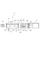
- FIG. 1 is an overall schematic diagram of an oil content measuring apparatus according to an embodiment of the present invention.
- the schematic diagram which shows the measuring apparatus main body in the embodiment.
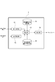
- the functional block diagram which shows the information processing apparatus in the embodiment.
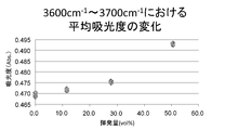
- data indicating that the influence of volatilization is canceled by the correction unit.
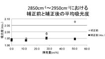
- data indicating that the influence of volatilization is canceled by the correction unit.
- the oil content measuring apparatus 100 of this embodiment is used for measuring the oil content contained in water collected from, for example, factory wastewater, rivers, oceans, and the like.
- FIG. 1 schematically shows the entire oil content measuring apparatus 100.
- reference numeral 1 denotes an extraction tank, in which a stirring blade plate 2 driven by a motor or a vibrator (not shown) is provided, and an inlet 1a for a sample and an extraction solvent is provided at the upper part. Is provided.
- a flow path 4 is connected to the lower part of the extraction tank 1 via an electromagnetic valve 3, and a measuring apparatus body 5 for measuring the oil concentration using the NDIR method is provided downstream of a filter 7 provided in the flow path 4. Is provided.
- the basic configuration of the oil content measuring device may be a configuration in which an operator inputs only a sample.
- a solvent tank (not shown) for storing the solvent is provided, and a predetermined amount of solvent is automatically supplied from the solvent tank to the extraction tank by a syringe pump or the like. That's fine.
- a sample without an extraction tank that is, a sample and a solvent may be separately stirred in a container to extract oil into the solvent, and the solvent from which the oil is extracted may be charged into the apparatus.
- the oil content measuring apparatus 100 is automatically measured thereafter. Specifically, in the extraction tank 1, the sample is stirred with the stirring member 2, and the oil contained in the sample is extracted into the solvent. Thereafter, the electromagnetic valve 3 is controlled, and the solvent containing oil is supplied to the measuring device main body 5 through the filter 7. And in this measuring apparatus main body 5, an oil concentration is measured, the measured value is output, for example, displayed on a display or stored in an external memory.
- a start button not shown
- the solvent used in the oil content measuring apparatus 100 is obtained by mixing a small amount of an additive into a solvent main body that dissolves oil.
- a halogenated olefin which hardly accumulates in the environment and has substantially no or little light absorption in the wavelength band used for measurement in the light absorption wavelength band of oil.
- Such halogenated olefins include, for example, cyclic materials having strain halogenated with fluorine, chlorine, etc., cyclic materials having halogenated double bonds, dichlorotetrafluoropropene, trichlorotrifluoropropene, dichlorohexa. Mention may be made of fluorobutene or dichlorooctafluoropentene, more specifically 1,1-dichloro-2,3,3,3-tetrafluoropropene and 1,3-dichloro-1,2,3,3 -Substances selected from tetrafluoropropene and mixtures thereof.
- Additives are called antioxidants, radical scavengers, dispersants, etc. that have a stabilizing effect on the halogenated olefin, and here, they are prominent in wavelength bands other than the wavelength band used for oil content measurement. Uses light absorption.
- 2,6-di-t-butylparacresol (3650 cm ⁇ 1 , 1700 cm ⁇ 1 ), 2,6-di-t-butylphenol (3650 cm ⁇ 1 , 1900 cm ⁇ 1 )
- N-phenyl-1-naphthylamine (3400 cm ⁇ 1 , 1900 cm ⁇ 1 )
- phenothiazine (3300 cm ⁇ 1 )
- butylhydroxyanisole 3400 cm ⁇ 1
- the inside of () has shown the light absorption wavelength band.
- the measuring device body 5 includes a cell 51, an infrared light source 52, photodetectors 531 to 533, optical filters 541 to 543, amplifiers 551 to 553, an information processing device 6 and the like. .
- the cell 51 is made of a cylindrical body 511 made of a material having excellent corrosion resistance such as stainless steel, and an infrared transmitting material (for example, quartz glass) that seals both ends of the body 511. Windows 512 and 513.
- the body portion 511 is partitioned into two spaces 511a and 511b. In the first space, an inlet 51a and an outlet 51b through which a solvent from which oil has been extracted are supplied and discharged are provided in 511a.
- the second space 511b is filled with a gas such as the atmosphere and is used as a reference to be described later.
- the infrared light source 52 is, for example, a ceramic light source that emits broad infrared light, is provided on one end side of the cell 51, and irradiates the cell 51 with infrared light through one window 512.
- the photodetectors 531 to 533 convert the intensity of received light into an electrical signal and output it, and here, for example, a pyroelectric type is used.
- the photodetectors 531 to 533 are arranged on the other end side of the cell 51 so as to receive infrared light introduced from one window 512 and passing through the cell 51 and coming out from the other window 513.
- three photodetectors 531 to 533 are arranged in parallel.
- the optical filters 541 to 543 are interference filters (bandpass filters), and are provided on the optical paths from the infrared light emitted from the cell 51 to the photodetectors 531 to 533, respectively.
- An optical filter (first optical filter) 541 provided in front of the first photodetector 531 is a first band in which infrared light having a transmitted wave number band of, for example, 2800 to 3100 cm ⁇ 1 , that is, a band in which light absorption by the oil component occurs. Only infrared light in one wavelength band is allowed to pass through.
- the optical filter (second optical filter) 542 provided in front of the second photodetector 532 is an infrared light having a transmitted wave number region of, for example, 3600 to 3700 cm ⁇ 1 , that is, a band in which absorption due to oil hardly occurs.
- a transmitted wave number region of, for example, 3600 to 3700 cm ⁇ 1 , that is, a band in which absorption due to oil hardly occurs.
- Reference numeral 56 denotes an optical chopper provided between the detector-side window 513 and the optical filters 541 to 543, which is driven by a motor (not shown) and intermittently transmits infrared light passing through the cell 51 at a predetermined cycle. To do.
- the amplifiers 551 to 553 are analog type amplifiers that amplify the electrical signals output from the respective photodetectors 531 to 533, convert the impedance thereof, and output the signals as light intensity signals to the information processing apparatus 6 at the subsequent stage. .
- the information processing device 6 is an electric circuit including a CPU, a memory, a communication port, various drivers, and the like in addition to an A / D converter that receives the light intensity signal and converts it into a digital format, and is stored in the memory
- the CPU and other peripheral devices cooperate in accordance with a predetermined program, the functions as the first measurement unit 61, the second measurement unit 62, the correction unit 63, and the like are exhibited as shown in FIG.
- the first measurement unit 61 receives the first light intensity signal, and based on the value, absorbs light in the first wavelength band of light transmitted through the cell 51 (hereinafter also referred to as first absorbance). Is calculated.
- the value of the light intensity signal that passes through the second space 511b of the cell 1 and is detected by the third photodetector 533 is used.
- the third optical filter 543 provided in the third photodetector 533 is a wide bandpass filter having a transmission wavelength band of 1 ⁇ m to 5 ⁇ m, for example, and is considered to be an average value of the light intensity of the light source 52.
- the absorbance is calculated by dividing the value of the first intensity signal by the value of the light intensity signal from the third photodetector 533 and taking the log.
- the first light intensity signal when the cell 51 is empty may be acquired and used as a reference.
- the second measurement unit 62 receives the second light intensity signal, and based on the value, absorbs light in the second wavelength band of light transmitted through the cell 51 (hereinafter also referred to as second absorbance). Is calculated. As with the first measurement unit 61, the value of the third light intensity signal is used for calculating the absorbance.
- the correction unit 63 corrects the first absorbance with the second absorbance, and calculates the oil concentration based on the corrected first absorbance. This will be described more specifically.
- the correction unit 63 first calculates the volatilization amount of the solvent (specifically, the halogenated olefin mainly composed of the solvent) from the second absorbance.
- the second absorbance is an absorbance in the wave number band that is affected only by the additive concentration and not the oil concentration. Since the additive hardly volatilizes as described above, when the halogenated olefin as the main solvent is volatilized, the concentration of the additive increases and the second absorbance changes from the value when there is no volatilization.
- the volatilization amount of the halogenated olefin can be calculated by measuring the second absorbance.
- the relationship between the volatilization amount and the second absorbance is obtained in advance by experiments or the like, and the relationship is stored in a table format or relational expression in the volatilization amount calculation storage unit 65 set in a predetermined area of the memory. It is memorized as.
- the correction unit 63 calculates the volatilization amount by substituting the measured second absorbance value into a table or a relational expression stored in the volatilization amount calculation storage unit 65.
- the correction unit 63 corrects the first absorbance based on the calculated volatilization amount.
- the 1st light absorbency by the solvent which does not contain an oil component changes according to the volatilization amount of a solvent main body (halogenated olefin).
- the cause lies in the additive as described above.
- the additive has light absorption in the same band as the light absorption band due to oil.
- the concentration of the additive in the solvent is sufficiently low, and there is almost no influence on the measurement.
- the correction unit 63 calculates the value of the first absorbance due to only the additive (hereinafter also referred to as additive-derived absorbance) based on the volatilization amount. Specifically, the relationship between the volatilization amount and the additive-derived absorbance is obtained in advance by experiments or the like, and the relationship is stored in the first absorbance correction storage unit 66 set in a predetermined area of the memory as a table format or a relational expression. I remember it.
- the correction unit 63 substitutes the volatilization amount calculated based on the second absorbance into the table or the relational expression stored in the first absorbance correction storage unit 66, and calculates the value of the additive-derived absorbance. .
- the correction unit 63 performs correction for removing the influence of the additive-derived absorbance from the measured first absorbance. Specifically, a correction value obtained based on the value of the additive-derived absorbance is subtracted from the measured value of the first absorbance to calculate the first absorbance based only on the oil (hereinafter also referred to as corrected first absorbance). To do.
- the correction value is represented by a multi-order function (for example, a quadratic function) of the additive-derived absorbance value.
- FIG. 4A shows the relationship between the absorbance and the volatilization amount in the second wavelength band obtained in the experiment.
- FIG. 4B shows the absorbance changed according to the volatilization amount even though the sample was the same before the correction. It can be seen that the absorbance is almost constant regardless of whether the effect of volatilization is cancelled.
- the correction unit 63 calculates the oil concentration based on the corrected first absorbance. Since the calculation method is already known, a description thereof is omitted here.
- the calculated oil concentration value is output to a display provided on the front surface of the apparatus by the display unit 64, for example.
- the effects of the oil content measuring apparatus 100 and the oil content measuring method disclosed in the present embodiment are as follows.
- Additives can prevent degradation and alteration of the solvent main component, and in that respect can guarantee measurement accuracy, and can reliably eliminate the light absorption effect of the additive added to the solvent. Even if the composition ratio of the solvent changes during storage, the oil concentration can be measured with extremely high accuracy.
- a solvent containing an additive can be used as a solvent, the selection range of the solvent main body is expanded, and even an unstable and highly volatile substance such as a halogenated olefin used in this embodiment can be extracted with oil. It becomes possible to select it as an application of oil content determination.
- the additive may have a light absorption band other than the first light absorption band, so the selection range is wide and safe. It is easy to select inexpensive materials.
- the significance of the present invention will be added. Recently, detection of a trace amount of oil of 1 ppm or less has been demanded. However, there are cases where the conventional method cannot sufficiently meet the demand. As a result of intensive studies by the inventor of the present invention, the present inventors have found that the cause is a change in oil extractability due to decomposition and alteration of the solvent itself, and concentration of oil and impurities due to volatilization of the solvent itself. The present invention has been made for the first time based on this finding.
- the present invention is not limited to the above embodiment.
- the influence of the solvent on the first absorbance is calculated through the volatility of the solvent, but the relationship directly indicating the change in the first absorbance relative to the change in the second absorbance without involving the volatility. May be used.
- the oil content measuring apparatus in the above embodiment has an extraction tank that automatically extracts the oil content in the sample in the solvent.
- the oil extraction solvent may be measured.
- the present invention can be variously modified without departing from the spirit of the present invention.
- the oil content measuring method etc. which can measure the oil content contained in a sample accurately can be provided.
Landscapes
- Physics & Mathematics (AREA)
- Spectroscopy & Molecular Physics (AREA)
- Health & Medical Sciences (AREA)
- Life Sciences & Earth Sciences (AREA)
- Chemical & Material Sciences (AREA)
- Analytical Chemistry (AREA)
- Biochemistry (AREA)
- General Health & Medical Sciences (AREA)
- General Physics & Mathematics (AREA)
- Immunology (AREA)
- Pathology (AREA)
- Investigating Or Analysing Materials By Optical Means (AREA)
Abstract
試料に含まれる油分を精度よく測定できる油分測定方法等を提供する。油分を抽出する溶媒主体及び該溶媒主体よりも揮発性の低い添加剤を混合した溶媒に試料を混合して、該試料に含まれる油分を前記溶媒中に抽出し、前記油分が抽出された溶媒である油分含有溶媒に光を照射し、油分による光吸収が認められる第1波長帯域での光吸収を測定する一方で、油分による光吸収が実質的になく、かつ、前記添加剤による光吸収がある第2波長帯域での光吸収を測定し、前記第1波長帯域での光吸収測定結果を第2波長帯域での光吸収測定結果によって補正して前記試料中の油分量又は油分濃度を算出する。
Description
この発明は、自然水や、工場、下水処理場などからの排水あるいは土壌等に含まれる油分濃度又は油分量を測定する油分測定方法および油分測定装置に関するものである。
自然水や排水などの試料に含まれる油分の測定方法として、油分を溶かしだす溶媒と前記試料とを所定の割合で混ぜ合わせ、油分が抽出された溶媒の光吸収を測定するという方法が知られている。
このときの光吸収測定では、例えば波長が3.4μm付近におけるC-H基の吸収を用いた赤外吸光法(以下、NDIR法ともいう。)が用いられる。そのため、前記溶媒として、特許文献1に示すように、前記3.4μm付近に光吸収のないもの、例えば、四塩化炭素、クロロトリフロロエチレンダイマー、ハイドロクロロフルオロカーボン、ハロゲン化オレフィン等が用いられている。
このときの光吸収測定では、例えば波長が3.4μm付近におけるC-H基の吸収を用いた赤外吸光法(以下、NDIR法ともいう。)が用いられる。そのため、前記溶媒として、特許文献1に示すように、前記3.4μm付近に光吸収のないもの、例えば、四塩化炭素、クロロトリフロロエチレンダイマー、ハイドロクロロフルオロカーボン、ハロゲン化オレフィン等が用いられている。
しかしながら、近時、微量油分の検出が要請されているところ、従来の方法では、その要請に対して十分に対応できない場合がある。
本発明はかかる不具合を解決すべくなされたものであって、その主たる所期課題は、試料に含まれる油分を、低い濃度であっても精度よく測定できる油分測定方法等を提供することにある。
すなわち、本発明に係る油分測定方法は、油分を抽出する溶媒主体及び該溶媒主体よりも揮発性の低い添加剤を混合した溶媒に試料を混合して、該試料に含まれる油分を前記溶媒中に抽出し、前記油分が抽出された溶媒に光を照射し、油分による光吸収が認められる第1波長帯域での光吸収を測定する一方で、油分による光吸収が実質的になく、かつ、前記添加剤による光吸収がある第2波長帯域での光吸収を測定し、前記第1波長帯域での光吸収測定結果を第2波長帯域での光吸収測定結果によって補正して前記試料中の油分量又は油分濃度を算出することを特徴とするものである。
かかる構成によれば、従来に比べより低い濃度での油分検出が可能になる。
その理由を以下に説明する。
まず、油分を抽出する溶媒主体の分解や変質を防止する分解・変質抑止剤を添加剤として用いることにより、溶媒主体が例えば保存中に分解・変質することによって生じる油分抽出能の低下を防止できる。その結果、低濃度での油分測定精度が向上する。
さらに、このように添加剤を入れても、油分が低濃度である場合には、無視できない測定誤差が生じる場合がある。その大きな原因の1つが、溶媒主体の揮発である。油分の抽出操作や測定時の温度上昇等によって揮発すると、添加剤の割合が相対的に増え、その濃度が高くなり、この添加剤による光吸収が測定上無視できないレベルとなって、測定誤差に繋がるわけである。この現象及び原因を本発明者は初めて見出したが、本発明によれば、この問題も解決できる。
すなわち、本発明では、第2波長帯域での光吸収を測定しており、その測定結果が、添加剤の溶媒に占める含有割合を間接的に示すものとなる。したがって、本発明のように、第1波長帯域での光吸収測定結果を、添加剤の影響度を示す第2波長帯域での光吸収測定結果で補正することによって、添加剤による第1波長帯域での光吸収測定結果の影響を排除でき、低濃度での極めて精度の高い油分濃度の測定が可能となる。
かかる構成によれば、従来に比べより低い濃度での油分検出が可能になる。
その理由を以下に説明する。
まず、油分を抽出する溶媒主体の分解や変質を防止する分解・変質抑止剤を添加剤として用いることにより、溶媒主体が例えば保存中に分解・変質することによって生じる油分抽出能の低下を防止できる。その結果、低濃度での油分測定精度が向上する。
さらに、このように添加剤を入れても、油分が低濃度である場合には、無視できない測定誤差が生じる場合がある。その大きな原因の1つが、溶媒主体の揮発である。油分の抽出操作や測定時の温度上昇等によって揮発すると、添加剤の割合が相対的に増え、その濃度が高くなり、この添加剤による光吸収が測定上無視できないレベルとなって、測定誤差に繋がるわけである。この現象及び原因を本発明者は初めて見出したが、本発明によれば、この問題も解決できる。
すなわち、本発明では、第2波長帯域での光吸収を測定しており、その測定結果が、添加剤の溶媒に占める含有割合を間接的に示すものとなる。したがって、本発明のように、第1波長帯域での光吸収測定結果を、添加剤の影響度を示す第2波長帯域での光吸収測定結果で補正することによって、添加剤による第1波長帯域での光吸収測定結果の影響を排除でき、低濃度での極めて精度の高い油分濃度の測定が可能となる。
具体的な実施態様としては、前記溶媒主体がハロゲン化オレフィンであり、前記添加剤がハロゲン化オレフィンを安定させる安定剤を挙げることができる。
前記添加剤としては、酸化防止剤、ラジカル補足剤又は分散剤等を挙げることができる。
前記添加剤としては、酸化防止剤、ラジカル補足剤又は分散剤等を挙げることができる。
また、本発明に係る油分測定装置は、油分を抽出する溶媒主体及び該溶媒主体よりも揮発性の低い添加剤を混合した溶媒と試料とを混合し、該試料中の油分を前記溶媒中に抽出する抽出槽と、前記油分が抽出された溶媒に光を照射し、その際の所定波長帯域での光吸収を測定することによって前記試料中の油分量又は油分濃度を測定する測定装置本体とを具備したものである。
そして、前記測定装置本体が、前記油分による光吸収が認められる第1波長帯域での光吸収を測定する第1測定部と、前記油分による光吸収が実質的になく、かつ、前記添加剤による光吸収がある第2波長帯域での光吸収を測定する第2測定部と、前記第1測定部での光吸収測定結果を第2測定部での光吸収測定結果によって補正して前記油分量又は油分濃度を算出する補正部とを具備するものであることを特徴とする。
そして、前記測定装置本体が、前記油分による光吸収が認められる第1波長帯域での光吸収を測定する第1測定部と、前記油分による光吸収が実質的になく、かつ、前記添加剤による光吸収がある第2波長帯域での光吸収を測定する第2測定部と、前記第1測定部での光吸収測定結果を第2測定部での光吸収測定結果によって補正して前記油分量又は油分濃度を算出する補正部とを具備するものであることを特徴とする。
本発明によれば、溶媒主体の揮発によって生じる油分濃度測定の誤差を、前記第2波長帯域での光吸収測定によって補正できる。また、溶媒主体の分解・変質に起因する油分濃度測定精度の低下を、添加剤によって抑制できる。したがって、本発明によれば、これらが相まって、特に低濃度での油分濃度測定精度を大きく向上させることができるようになる。
100・・・油分測定装置
1・・・抽出槽
5・・・測定装置本体
61・・・第1測定部
62・・・第2測定部
63・・・補正部
1・・・抽出槽
5・・・測定装置本体
61・・・第1測定部
62・・・第2測定部
63・・・補正部
以下に本発明に係る油分測定装置の一実施形態について説明する。
本実施形態の油分測定装置100は、例えば工場排水等や、河川・海洋等で採取された水に含まれる油分濃度を測定するために用いられるものである。
本実施形態の油分測定装置100は、例えば工場排水等や、河川・海洋等で採取された水に含まれる油分濃度を測定するために用いられるものである。
その概要をまず説明する。
図1は、この油分測定装置100の全体を概略的に示すものである。この図1において、1は抽出槽で、その内部には、図示しないモータやバイブレータによって駆動される攪拌羽根板2が設けられており、その上部には、試料および抽出用溶媒の注入口1aが設けられている。抽出槽1の下部には電磁弁3を介して流路4が接続され、この流路4に設けられたフィルタ7の下流には、NDIR法を利用して油分濃度を測定する測定装置本体5が設けられている。
図1は、この油分測定装置100の全体を概略的に示すものである。この図1において、1は抽出槽で、その内部には、図示しないモータやバイブレータによって駆動される攪拌羽根板2が設けられており、その上部には、試料および抽出用溶媒の注入口1aが設けられている。抽出槽1の下部には電磁弁3を介して流路4が接続され、この流路4に設けられたフィルタ7の下流には、NDIR法を利用して油分濃度を測定する測定装置本体5が設けられている。
このような油分測定装置100を用いて試料の油分を測定する場合は、まず、オペレータがそれぞれ計量された試料(ここでは油分を含んだ液体)と油分抽出用の溶媒とを抽出槽1に投入する。
なお、この油分測定装置の基本構成としては、オペレータが、試料のみを投入する構成のものでもかまわない。その場合は、溶媒を貯留している図示しない溶媒槽が設けられており、その溶媒槽から予め定められた量の溶媒がシリンジポンプなどによって前記抽出槽に自動投入されるように構成してあればよい。また、抽出槽がないもの、すなわち、試料と溶媒とを別途、容器で攪拌して溶媒中に油分を抽出し、この油分が抽出された溶媒を装置に投入するものでも構わない。
次に、オペレータが図示しないスタートボタンを押すと、その後は、全て自動で油分の測定が行われる。
具体的には、抽出槽1において、攪拌部材2による試料と攪拌がなされ、試料中に含まれる油分が溶媒に抽出される。その後、電磁弁3が制御されて、油分を含んだ溶媒がフィルタ7を介して測定装置本体5に供給される。そして、この測定装置本体5において、油分濃度が測定され、その測定値が出力されて、例えばディスプレイに表示されたり、外部メモリに格納されたりする。
以上が、油分測定装置100の概要である。
具体的には、抽出槽1において、攪拌部材2による試料と攪拌がなされ、試料中に含まれる油分が溶媒に抽出される。その後、電磁弁3が制御されて、油分を含んだ溶媒がフィルタ7を介して測定装置本体5に供給される。そして、この測定装置本体5において、油分濃度が測定され、その測定値が出力されて、例えばディスプレイに表示されたり、外部メモリに格納されたりする。
以上が、油分測定装置100の概要である。
次に、この油分測定装置100で用いられる溶媒について説明する。
本実施形態で用いられる溶媒は、油分を溶かしだす溶媒主体に微小量の添加剤を混入させたものである。
本実施形態で用いられる溶媒は、油分を溶かしだす溶媒主体に微小量の添加剤を混入させたものである。
溶媒主体としては、環境中に蓄積しにくく、油分の光吸収波長帯域のうち、測定に用いられる波長帯域において、光吸収が実質的にないもしくは少ない例えばハロゲン化オレフィンを用いている。
このようなハロゲン化オレフィンとしては、例えば、フッ素や塩素等でハロゲン化されたひずみを持つ環状物質、ハロゲン化された二重結合を持つ環状物質、ジクロロテトラフルオロプロペン、トリクロロトリフルオロプロペン、ジクロロヘキサフルオロブテン又はジクロロオクタフルオロペンテンを挙げることができ、より具体的には、1,1-ジクロロ-2,3,3,3-テトラフルオロプロペンおよび1,3-ジクロロ-1,2,3,3-テトラフルオロプロペンなどから選ばれる物質やこれらの混合物が挙げられる。
添加剤は、前記ハロゲン化オレフィンの安定化作用を有する酸化防止剤、ラジカル補足剤、分散剤などと称されるものであり、ここでは、油分測定に用いられる波長帯域以外の波長帯域に、顕著な光吸収が見られるものを用いている。
具体的にはフェノール系であれば、2,6-ジ-t-ブチルパラクレゾール(3650cm-1, 1700cm-1)や2,6-ジ-t-ブチルフェノール(3650cm-1, 1900cm-1)、また、アミン系であれば、N-フェニル-1-ナフチルアミン(3400cm-1, 1900cm-1)、フェノチアジン(3300cm-1)、ブチルヒドロキシアニソール(3400cm-1)を用いている。
なお、()内は光吸収波長帯域を示している。
なお、()内は光吸収波長帯域を示している。
これら添加剤は、ハロゲン化オレフィンに比べて遥かに揮発性の低いものであり、この油分測定装置100で想定されている推奨測定環境下では、ほとんど揮発しない。
次に、前記測定装置本体5の構成や動作について説明する。
この測定装置本体5は、図2に示すように、セル51、赤外光源52、光検出器531~533、光フィルタ541~543、増幅器551~553、情報処理装置6等から構成されている。
この測定装置本体5は、図2に示すように、セル51、赤外光源52、光検出器531~533、光フィルタ541~543、増幅器551~553、情報処理装置6等から構成されている。
前記セル51は、ステンレス鋼など耐腐蝕性に優れた素材で形成された筒状の胴体部511と、該胴体部511の両端部を封止する赤外線透過性素材(例えば石英ガラスなど)よりなる窓512、513とを具備するものである。前記胴体部511は、2つの空間511a、511bに仕切られている。その第1空間には511aには、油分が抽出された溶媒が供給・排出される導入口51a及び導出口51bが設けられている。また、第2空間511bは、大気などのガスが充填されており、後述するリファレンスに用いられる。
赤外光源52は、ブロードな赤外光を射出する例えばセラミック光源であり、セル51の一端側に設けられて、一方の窓512を介してセル51内に赤外光を照射する。
光検出器531~533は、受光した光の強度を電気信号に変換して出力するものであり、ここでは、例えば焦電型のものが用いられている。この光検出器531~533は、一方の窓512から導入され、セル51内を通過して他方の窓513から出てきた赤外光を受光できるように、セル51の他端側に配置されており、ここでは3つの光検出器531~533が並設されている。
光フィルタ541~543は、干渉フィルタ(バンドパスフィルタ)であり、セル51から出た赤外光の前記各光検出器531~533に至るまでの光路上にそれぞれ設けられている。
第1光検出器531の前面に設けられた光フィルタ(第1光フィルタ)541は、透過波数帯域が例えば2800~3100cm-1の赤外光、すなわち前記油分による光吸収が生じる帯域である第1波長帯域の赤外光のみを通過させるものである。
第2光検出器532の前面に設けられた光フィルタ(第2光フィルタ)542は、透過波数領域が例えば3600~3700cm-1の赤外光、すなわち、油分による吸収のほとんど生じない帯域であって、前記添加剤の光吸収が認められる帯域である第2波長帯域の赤外光のみを通過させるものである。
なお、第3光検出器533と、その前段に配置した第3光フィルタ543は、後述するが、リファレンスとして用いられるものである。
また、符号56は、検出器側の窓513と光フィルタ541~543との間に設けられる光チョッパで、図示しないモータによって駆動され、セル51を通過してきた赤外光を所定の周期で断続するものである。
また、符号56は、検出器側の窓513と光フィルタ541~543との間に設けられる光チョッパで、図示しないモータによって駆動され、セル51を通過してきた赤外光を所定の周期で断続するものである。
増幅器551~553は、前記各光検出器531~533から出力される電気信号を増幅するとともにそのインピーダンスを変換し、後段にある情報処理装置6に光強度信号として出力するアナログ式のものである。
情報処理装置6は、前記光強度信号を受信してデジタル形式に変換するA/Dコンバータの他、CPU、メモリ、通信ポート、各種ドライバなどを具備した電気回路であり、前記メモリに記憶された所定のプログラムに従ってCPUやその他の周辺機器が協働することによって、図3に示すように、第1測定部61、第2測定部62、補正部63等としての機能を発揮する。
第1測定部61は、前記第1光強度信号を受信して、その値から、セル51を透過した光のうちの、前記第1波長帯域での吸光度(以下、第1吸光度ともいう。)を算出するものである。
なお、吸光度の算出について既知ではあるが、ここで簡単に説明しておく。吸光度の算出にはリファレンス(光吸収がないときの、あるいは光吸収が既知の光強度)が必要となる。そのために、この実施形態では、セル1の第2空間511bを通過して、前記第3光検出器533で検出された光強度信号の値を用いている。この第3光検出器533に設けられた第3光フィルタ543は、例えば透過波長帯域が1μm~5μmといった幅の広いバンドパスフィルタであり、光源52の光強度を平均した値と考えられるから、この第3光検出器533による光強度信号の値によって前記第1強度信号の値を除算し、そのlogをとることによって、吸光度を算出している。その他、例えばセル51が空のときの第1光強度信号を取得してこれをリファレンスとして用いるようにしてもよい。
第2測定部62は、前記第2光強度信号を受信して、その値から、セル51を透過した光のうちの、前記第2波長帯域での吸光度(以下、第2吸光度ともいう。)を算出するものである。吸光度の算出には、第1測定部61同様、前記第3光強度信号の値を用いる。
補正部63は、前記第1吸光度を第2吸光度によって補正し、その補正した第1吸光度に基づいて油分濃度を算出するものである。
より具体的に説明する。
より具体的に説明する。
この補正部63は、第2吸光度から溶媒(具体的には溶媒主体であるハロゲン化オレフィン)の揮発量をまず算出する。
第2吸光度は、前述したように、添加剤濃度の影響のみを受け、油分濃度の影響を受けない波数帯域での吸光度である。そして、前述したように添加剤はほとんど揮発しないので、溶媒主体たるハロゲン化オレフィンが揮発すると、添加剤の濃度は高くなり、この第2吸光度が揮発のないときの値から変化することとなる。
第2吸光度は、前述したように、添加剤濃度の影響のみを受け、油分濃度の影響を受けない波数帯域での吸光度である。そして、前述したように添加剤はほとんど揮発しないので、溶媒主体たるハロゲン化オレフィンが揮発すると、添加剤の濃度は高くなり、この第2吸光度が揮発のないときの値から変化することとなる。
したがって、この第2吸光度を測定すれば、ハロゲン化オレフィンの揮発量を算出できるわけである。
この実施形態では、溶媒において、揮発量と第2吸光度との関係が予め実験等で求められており、その関係がメモリの所定領域に設定した揮発量算出用記憶部65にテーブル形式又は関係式として記憶させてある。
この補正部63は、測定された第2吸光度の値を、前記揮発量算出用記憶部65に格納してあるテーブル又は関係式に代入して、揮発量を算出する。
次に補正部63は、算出した揮発量に基づいて、第1吸光度を補正する。
油分を含まない溶媒による第1吸光度は、溶媒主体(ハロゲン化オレフィン)の揮発量に応じて変化する。その原因は前述したように、添加剤にある。
油分を含まない溶媒による第1吸光度は、溶媒主体(ハロゲン化オレフィン)の揮発量に応じて変化する。その原因は前述したように、添加剤にある。
添加剤は、油分による光吸収帯域と同じ帯域に光吸収がある。そして溶媒主体が揮発していない初期状態であれば、この添加剤の溶媒における濃度は十分に低く、測定に対する影響はほとんどない。
しかしながら、溶媒主体が揮発し、添加剤の溶媒における濃度が高くなると、この添加剤による光吸収が無視できなくなり、測定された第1吸光度が油分にのみ起因する値よりも大きくなる。
したがって、補正部63は、前記揮発量に基づいて、添加剤のみによる第1吸光度(以下、添加剤由来吸光度ともいう。)の値を算出する。
具体的には、揮発量と添加剤由来吸光度との関係が予め実験等で求められており、その関係がメモリの所定領域に設定した第1吸光度補正用記憶部66にテーブル形式又は関係式として記憶させてある。
具体的には、揮発量と添加剤由来吸光度との関係が予め実験等で求められており、その関係がメモリの所定領域に設定した第1吸光度補正用記憶部66にテーブル形式又は関係式として記憶させてある。
該補正部63は、第2吸光度に基づいて算出された揮発量を、前記第1吸光度補正用記憶部66に格納してあるテーブル又は関係式に代入し、添加剤由来吸光度の値を算出する。
次に、この補正部63は、測定された第1吸光度から、添加剤由来吸光度の影響を除去する補正を行う。具体的には、測定された第1吸光度の値から、添加剤由来吸光度の値に基づいて求めた補正値を差し引き、油分のみによる第1吸光度(以下、補正第1吸光度ともいう。)を算出する。なお、前記補正値とは、添加剤由来吸光度の値の多次関数(ここでは例えば二次関数)で表されるものである。
その例を、図4Aおよび図4Bに示す。図4Aは、実験で求めた第2波長帯域における吸光度と揮発量の関係を示している。この関係に基づいて第1吸光度を補正すると、図4Bに示すように、補正前には、同一サンプルであるにもかかわらず、揮発量によって吸光度が変化していたものが、補正後、揮発量にかかわらず吸光度がほぼ一定となり、揮発の影響がキャンセルされていることがわかる。
その後、該補正部63は、前記補正第1吸光度に基づいて、油分濃度を算出する。その算出方式については既知のため、ここでの説明は省略する。
算出された油分濃度の値は、例えば、表示部64によって装置前面に設けられたディスプレイに出力される。
算出された油分濃度の値は、例えば、表示部64によって装置前面に設けられたディスプレイに出力される。
しかして、本実施形態に開示された油分測定装置100及び油分測定方法の効果は以下のようなものである。
添加剤によって溶媒主体の分解・変質を防止でき、その点において測定精度を担保できるうえ、溶媒中に添加されている添加剤の光吸収影響を確実に排除できるので、溶媒主体として、その揮発によって溶媒の組成比が保存中に変化しても、油分濃度を極めて精度良く測定することが可能になる。
添加剤によって溶媒主体の分解・変質を防止でき、その点において測定精度を担保できるうえ、溶媒中に添加されている添加剤の光吸収影響を確実に排除できるので、溶媒主体として、その揮発によって溶媒の組成比が保存中に変化しても、油分濃度を極めて精度良く測定することが可能になる。
また、溶媒として添加剤を含有するものを用いることができるので、溶媒主体の選択範囲が広がり、この実施形態で用いたハロゲン化オレフィンのように、不安定で揮発性の高い物質でも油分抽出と油分定量の用途として選択できるようになる。
さらに、添加剤においても、第1光吸収帯域以外に光吸収帯域があることは必須ではあるものの、第1光吸収帯域に光吸収帯域があっても構わないので、その選択範囲は広く、安全で安価な物質を選ぶことが容易にできる。
ここで、本発明の意義について付言しておく。
近時、1ppm以下の微量油分の検出が要請されているところ、従来の方法では、その要請に対して十分に対応できない場合があった。その原因を本発明者が鋭意検討した結果、溶媒自体の分解や変質による油分抽出能の変化、溶媒自体の揮発による油分や不純物の濃縮などが原因であることを突き止めた。本発明は、この知見によって初めてなされたものである。
ここで、本発明の意義について付言しておく。
近時、1ppm以下の微量油分の検出が要請されているところ、従来の方法では、その要請に対して十分に対応できない場合があった。その原因を本発明者が鋭意検討した結果、溶媒自体の分解や変質による油分抽出能の変化、溶媒自体の揮発による油分や不純物の濃縮などが原因であることを突き止めた。本発明は、この知見によって初めてなされたものである。
なお、本発明は前記実施形態に限られるものではない。
前記実施形態では、溶媒主体の揮発度を介して溶媒による第1吸光度への影響を算出していたが、揮発度を介在させず、第2吸光度の変化に対する第1吸光度の変化を直接示す関係を用いても構わない。
前記実施形態では、溶媒主体の揮発度を介して溶媒による第1吸光度への影響を算出していたが、揮発度を介在させず、第2吸光度の変化に対する第1吸光度の変化を直接示す関係を用いても構わない。
すなわち、油分が抽出されていない未使用の溶媒において、第2吸光度の各値と第1吸光度の値との関係(すなわち、第2吸光度の変化に対する第1吸光度への影響度)を実験等によって求めておく。
そして、油分測定時には、測定された第2吸光度を前記関係にあてはめて、溶媒による第1吸光度への影響度を算出し、その影響度をキャンセルするように、実際に測定した第1吸光度を補正しても構わない。
また、前記実施形態における油分測定装置は、溶媒に試料中の油分を自動抽出する抽出槽を具備していたが、これを有さないもの、すなわち、別途、溶媒に試料を混合して生成された油分抽出溶媒を測定するようにしたものでも構わない。
その他、本発明はその趣旨を逸脱しない範囲で種々変形が可能である。
また、前記実施形態における油分測定装置は、溶媒に試料中の油分を自動抽出する抽出槽を具備していたが、これを有さないもの、すなわち、別途、溶媒に試料を混合して生成された油分抽出溶媒を測定するようにしたものでも構わない。
その他、本発明はその趣旨を逸脱しない範囲で種々変形が可能である。
本発明によれば、試料に含まれる油分を精度よく測定できる油分測定方法等を提供できる。
Claims (6)
- 油分を抽出する溶媒主体及び該溶媒主体よりも揮発性の低い添加剤を混合した溶媒に試料を混合して、該試料に含まれる油分を前記溶媒中に抽出し、
前記油分が抽出された溶媒である油分含有溶媒に光を照射し、
油分による光吸収が認められる第1波長帯域での光吸収を測定する一方で、油分による光吸収が実質的になく、かつ、前記添加剤による光吸収がある第2波長帯域での光吸収を測定し、
前記第1波長帯域での光吸収測定結果を第2波長帯域での光吸収測定結果によって補正して前記試料中の油分量又は油分濃度を算出することを特徴とする油分測定方法。 - 前記溶媒主体がハイドロクロロフルオロカーボン、四塩化炭素、クロロトリフルオロエチレンダイマー、テトラクロロエチレン、トリクロロエチレン、ジクロロエチレン又はハロゲン化オレフィンであり、前記添加剤が前記溶媒主体を安定させる安定剤である請求項1記載の油分測定方法。
- 前記添加剤が、酸化防止剤、ラジカル補足剤、粘度改良剤、物性改良剤、洗浄剤又は分散剤である請求項1記載の油分測定方法。
- 油分を含まない溶媒において、溶媒主体の揮発度と第1波長帯域での光吸収との関係である第1関係及び溶媒主体の揮発度と第2波長帯域での光吸収との関係である第2関係をそれぞれ求めておき、
前記油分含有溶媒における第2波長帯域での光吸収の測定結果を、前記第2関係にあてはめて前記溶媒主体の揮発度を算出し、
算出した前記揮発度を前記第1関係にあてはめて、油分を含まない溶媒における第1波長帯域での光吸収を算出し、
前記油分含有溶媒における第1波長帯域での光吸収の測定結果を、前記算出した第1波長帯域での光吸収によって補正し、
この補正した光吸収に基づいて前記油分量又は油分濃度を算出することを特徴とする請求項1記載の油分測定方法。 - 油分を抽出する溶媒主体及び該溶媒主体よりも揮発性の低い添加剤を混合した溶媒に試料が混合されて、該試料中の油分が前記溶媒中に抽出されて生成された油分含有溶媒に光を照射し、その際の所定波長帯域での光吸収を測定することによって前記試料中の油分量又は油分濃度を測定する測定装置本体を具備し、
該測定装置本体が、
前記油分による光吸収が認められる第1波長帯域での光吸収を測定する第1測定部と、
前記油分による光吸収が実質的になく、かつ、前記添加剤による光吸収がある第2波長帯域での光吸収を測定する第2測定部と、
前記第1測定部での光吸収測定結果を第2測定部での光吸収測定結果によって補正して前記油分量又は油分濃度を算出する補正部とを具備することを特徴とする油分測定装置。 - 前記溶媒主体及び添加剤を混合した溶媒と試料とを混合し、該試料中の油分を前記溶媒中に抽出する抽出槽をさらに具備することを特徴とする請求項5記載の油分測定装置。
Applications Claiming Priority (2)
| Application Number | Priority Date | Filing Date | Title |
|---|---|---|---|
| JP2016-099421 | 2016-05-18 | ||
| JP2016099421A JP2019143971A (ja) | 2016-05-18 | 2016-05-18 | 油分測定方法及び油分測定装置 |
Publications (1)
| Publication Number | Publication Date |
|---|---|
| WO2017199611A1 true WO2017199611A1 (ja) | 2017-11-23 |
Family
ID=60324996
Family Applications (1)
| Application Number | Title | Priority Date | Filing Date |
|---|---|---|---|
| PCT/JP2017/014112 Ceased WO2017199611A1 (ja) | 2016-05-18 | 2017-04-04 | 油分測定方法及び油分測定装置 |
Country Status (2)
| Country | Link |
|---|---|
| JP (1) | JP2019143971A (ja) |
| WO (1) | WO2017199611A1 (ja) |
Cited By (2)
| Publication number | Priority date | Publication date | Assignee | Title |
|---|---|---|---|---|
| CN110646255A (zh) * | 2018-06-26 | 2020-01-03 | 株式会社堀场先进技术 | 油分提取剂 |
| CN112730279A (zh) * | 2020-11-20 | 2021-04-30 | 风帆有限责任公司 | 一种蓄电池连铸板栅表面脱模油含量的测试方法 |
Families Citing this family (1)
| Publication number | Priority date | Publication date | Assignee | Title |
|---|---|---|---|---|
| JP7584266B2 (ja) * | 2020-10-02 | 2024-11-15 | 住友重機械工業株式会社 | レーザ制御装置、パルスレーザビーム出力方法、及びプログラム |
Citations (8)
| Publication number | Priority date | Publication date | Assignee | Title |
|---|---|---|---|---|
| JPS61500277A (ja) * | 1983-11-01 | 1986-02-20 | ジェネシス・(ユ−・ケ−)・リミテッド | ドリル穴からの物質の分析 |
| JP2003083887A (ja) * | 2001-06-28 | 2003-03-19 | Advantest Corp | 化学物質検出方法及び装置 |
| JP2006145498A (ja) * | 2004-11-24 | 2006-06-08 | Horiba Ltd | 油分濃度測定方法および油分濃度測定装置 |
| WO2007089154A1 (en) * | 2006-02-01 | 2007-08-09 | Must As | Method and application to determine the amount of oil or condensate in water or in water-based samples with the help of an extractive agent |
| JP2008008622A (ja) * | 2006-06-27 | 2008-01-17 | Showa Shell Sekiyu Kk | 油分測定方法 |
| JP2015121410A (ja) * | 2013-12-20 | 2015-07-02 | 旭硝子株式会社 | 油分濃度測定方法および油分濃度測定装置 |
| JP2015135323A (ja) * | 2013-12-20 | 2015-07-27 | 築野食品工業株式会社 | 近赤外分光法を用いた植物油脂またはその原料中の遊離脂肪酸の定量方法 |
| JP2015169627A (ja) * | 2014-03-10 | 2015-09-28 | 広島県 | ビタミンa測定装置及びビタミンa測定システム |
-
2016
- 2016-05-18 JP JP2016099421A patent/JP2019143971A/ja active Pending
-
2017
- 2017-04-04 WO PCT/JP2017/014112 patent/WO2017199611A1/ja not_active Ceased
Patent Citations (8)
| Publication number | Priority date | Publication date | Assignee | Title |
|---|---|---|---|---|
| JPS61500277A (ja) * | 1983-11-01 | 1986-02-20 | ジェネシス・(ユ−・ケ−)・リミテッド | ドリル穴からの物質の分析 |
| JP2003083887A (ja) * | 2001-06-28 | 2003-03-19 | Advantest Corp | 化学物質検出方法及び装置 |
| JP2006145498A (ja) * | 2004-11-24 | 2006-06-08 | Horiba Ltd | 油分濃度測定方法および油分濃度測定装置 |
| WO2007089154A1 (en) * | 2006-02-01 | 2007-08-09 | Must As | Method and application to determine the amount of oil or condensate in water or in water-based samples with the help of an extractive agent |
| JP2008008622A (ja) * | 2006-06-27 | 2008-01-17 | Showa Shell Sekiyu Kk | 油分測定方法 |
| JP2015121410A (ja) * | 2013-12-20 | 2015-07-02 | 旭硝子株式会社 | 油分濃度測定方法および油分濃度測定装置 |
| JP2015135323A (ja) * | 2013-12-20 | 2015-07-27 | 築野食品工業株式会社 | 近赤外分光法を用いた植物油脂またはその原料中の遊離脂肪酸の定量方法 |
| JP2015169627A (ja) * | 2014-03-10 | 2015-09-28 | 広島県 | ビタミンa測定装置及びビタミンa測定システム |
Cited By (4)
| Publication number | Priority date | Publication date | Assignee | Title |
|---|---|---|---|---|
| CN110646255A (zh) * | 2018-06-26 | 2020-01-03 | 株式会社堀场先进技术 | 油分提取剂 |
| JP2020003480A (ja) * | 2018-06-26 | 2020-01-09 | 株式会社 堀場アドバンスドテクノ | 油分抽出剤 |
| JP7263130B2 (ja) | 2018-06-26 | 2023-04-24 | 株式会社 堀場アドバンスドテクノ | 油分抽出剤 |
| CN112730279A (zh) * | 2020-11-20 | 2021-04-30 | 风帆有限责任公司 | 一种蓄电池连铸板栅表面脱模油含量的测试方法 |
Also Published As
| Publication number | Publication date |
|---|---|
| JP2019143971A (ja) | 2019-08-29 |
Similar Documents
| Publication | Publication Date | Title |
|---|---|---|
| WO2017199611A1 (ja) | 油分測定方法及び油分測定装置 | |
| US9423340B2 (en) | Aqueous ozone monitor utilizing gas stripping | |
| US9791430B2 (en) | Measurement of total organic carbon | |
| CN103630522A (zh) | 一种有色可溶性有机物三维荧光数据的校正和定标方法 | |
| TW201315997A (zh) | 用來監測和控制廢水程序流的方法 | |
| JP7790344B2 (ja) | 水質分析計及び水質分析方法 | |
| CN105531579A (zh) | 用于确定可变形容器中的物质的浓度的方法 | |
| JP2016523373A5 (ja) | ||
| KR20170121351A (ko) | 흡광광도법을 이용한 농도 측정 장치 및 방법 | |
| CN115452751A (zh) | 余氯检测方法及装置 | |
| CN114424050B (zh) | 海水中的总氯的检测 | |
| CN102495024B (zh) | 盐分浓度测定装置以及盐分浓度测定方法 | |
| US10788416B2 (en) | Multiple wavelength light source for colorimetric measurement | |
| CN116261659A (zh) | 水质分析装置 | |
| Xue-song et al. | Progress and prospect of application of miniatured near infrared spectrometers | |
| WO2012001633A3 (en) | Apparatus for the measurement of the gas concentration in a sealed container | |
| US20210053841A1 (en) | Determination of hydroxyl radical scavenging capacity and related techniques in advanced oxidative processes | |
| Xiong et al. | Hollow-waveguide-based carbon dioxide sensor for capnography | |
| US20150096349A1 (en) | Optimize analyte dynamic range in gas chromatography | |
| JP4048139B2 (ja) | 濃度測定装置 | |
| JP4459791B2 (ja) | 油分濃度測定方法および油分濃度測定装置 | |
| JP2012058105A (ja) | 光学式分析計 | |
| JP2015021932A (ja) | 気泡検出器及び気泡検出方法 | |
| JP4550626B2 (ja) | 鉛濃度の測定法 | |
| KR101571859B1 (ko) | 원자 흡광법을 이용한 원소 농도 분석 장치 및 방법 |
Legal Events
| Date | Code | Title | Description |
|---|---|---|---|
| NENP | Non-entry into the national phase |
Ref country code: DE |
|
| 121 | Ep: the epo has been informed by wipo that ep was designated in this application |
Ref document number: 17799045 Country of ref document: EP Kind code of ref document: A1 |
|
| 122 | Ep: pct application non-entry in european phase |
Ref document number: 17799045 Country of ref document: EP Kind code of ref document: A1 |
|
| NENP | Non-entry into the national phase |
Ref country code: JP |