WO2017195837A1 - ファンシュラウド - Google Patents
ファンシュラウド Download PDFInfo
- Publication number
- WO2017195837A1 WO2017195837A1 PCT/JP2017/017733 JP2017017733W WO2017195837A1 WO 2017195837 A1 WO2017195837 A1 WO 2017195837A1 JP 2017017733 W JP2017017733 W JP 2017017733W WO 2017195837 A1 WO2017195837 A1 WO 2017195837A1
- Authority
- WO
- WIPO (PCT)
- Prior art keywords
- fan shroud
- wall
- fan
- circular wall
- circular
- Prior art date
- Legal status (The legal status is an assumption and is not a legal conclusion. Google has not performed a legal analysis and makes no representation as to the accuracy of the status listed.)
- Ceased
Links
Images








Classifications
-
- F—MECHANICAL ENGINEERING; LIGHTING; HEATING; WEAPONS; BLASTING
- F04—POSITIVE - DISPLACEMENT MACHINES FOR LIQUIDS; PUMPS FOR LIQUIDS OR ELASTIC FLUIDS
- F04D—NON-POSITIVE-DISPLACEMENT PUMPS
- F04D29/00—Details, component parts, or accessories
- F04D29/40—Casings; Connections of working fluid
- F04D29/52—Casings; Connections of working fluid for axial pumps
- F04D29/54—Fluid-guiding means, e.g. diffusers
-
- F—MECHANICAL ENGINEERING; LIGHTING; HEATING; WEAPONS; BLASTING
- F04—POSITIVE - DISPLACEMENT MACHINES FOR LIQUIDS; PUMPS FOR LIQUIDS OR ELASTIC FLUIDS
- F04D—NON-POSITIVE-DISPLACEMENT PUMPS
- F04D29/00—Details, component parts, or accessories
- F04D29/66—Combating cavitation, whirls, noise, vibration or the like; Balancing
Definitions
- the present disclosure relates to a fan shroud that allows air to flow from an inlet to an outlet.
- Patent Document 1 A fan shroud that allows air to flow from a suction port to a blow-out port and that is intended to reduce rotational noise is disclosed in Patent Document 1 below.
- the first aspect of the fan shroud described in the following Patent Document 1 has a narrow edge with a short distance from the outer edge of the fan shroud to the outer periphery of the fan as compared with other parts. It is formed at a position advanced in the rotational direction, and has a protruding edge portion that protrudes upstream of the intake air from the fan and protrudes outward from the air guide portion.
- the second aspect of the fan shroud has a narrow edge portion whose outer edge of the fan shroud has a shorter distance to the outer periphery of the fan than other portions, and is advanced from the narrow edge portion in the fan rotation direction. And a shielding plate that is arranged downstream of the intake air from the fan and extends a predetermined length from the cylindrical portion toward the center of the fan.
- the protruding edge portion protruding from the outer edge portion of the fan shroud since the protruding edge portion protruding from the outer edge portion of the fan shroud is provided, the physique toward the outer peripheral direction of the fan becomes large, and the mountability to the vehicle is reduced.
- the shielding plate since the shielding plate is provided so as to block the flow of air, the air flow rate is reduced.
- This disclosure is intended to provide a fan shroud that can reduce rotational noise without deteriorating the mountability and without affecting the air flow rate.
- the present disclosure is a fan shroud that allows air to flow from a suction port to a blow-out port, the bell mouth part (23) that forms the blow-out port and has a circular wall (231) so as to accommodate a propeller fan, and the suction A rectangular portion (21) that forms a mouth and has a proximity wall (211 and 212) adjacent to the circular wall and a separation wall (213 and 214) that is separated from the circular wall rather than the proximity wall; It has.
- the proximity wall has a closest region (211a, 212a) closest to the circular wall.
- the circular wall is provided with extension wall portions (232, 233, 232A, 233A, 232B, 233B, 232C, 232D, 232E, 232F) extending in the axial direction of the propeller fan rather than the remaining portion, and the extension wall The portion is provided along the rotation direction of the propeller fan from a position facing the closest region.
- the extension wall portion by providing the extension wall portion, it is possible to achieve both the generation of the axial flow Fa and the suppression of the vortex flow Fb, and to reduce the rotational noise.
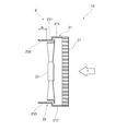
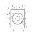
- FIG. 1 is a front view of a fan shroud according to the first embodiment.
- FIG. 2 is a cross-sectional view showing a II-II cross section of FIG.
- FIG. 3 is a partially enlarged view of FIG.
- FIG. 4 is a diagram for explaining a comparative example with respect to FIG.
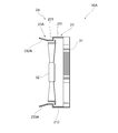
- FIG. 5 is a sectional view of a fan shroud according to the second embodiment.
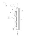
- FIG. 6 is a sectional view of a fan shroud according to the third embodiment.
- 7 is a cross-sectional view showing a VII-VII cross section of FIG.
- FIG. 8 is a sectional view of a fan shroud according to the fourth embodiment.
- FIG. 9 is a cross-sectional view of a fan shroud according to the fifth embodiment.
- FIG. 1 is a front view of a fan shroud according to the first embodiment.
- FIG. 2 is a cross-sectional view showing a II-II cross section of FIG.
- FIG. 10 is a sectional view of a fan shroud according to the sixth embodiment.
- FIG. 11 is a cross-sectional view of a fan shroud according to the seventh embodiment.
- FIG. 12 is a front view of a fan shroud that is a modification of the first embodiment.
- FIG. 13 is a front view of a fan shroud that is a modification of the first embodiment.
- the fan shroud 2 according to the first embodiment is applied to a vehicle cooling system 10.
- the vehicle cooling system 10 includes a fan shroud 2, a heat exchanger 31, a propeller fan 32, and a drive motor (not shown).
- the heat exchanger 31 functions as a condenser used for an air conditioner or a radiator used for cooling a traveling engine.
- One heat exchanger 31 may function as a condenser or a radiator, or two heat exchangers 31 function as each.
- the capacitor is a device that constitutes the refrigeration cycle of the air conditioner.
- the condenser is provided with an air flow path so that the high-temperature and high-pressure refrigerant gas circulated from the compressor exchanges heat with the outside air.
- the refrigerant condensed and liquefied by heat exchange with air flows out to the downstream equipment constituting the refrigeration cycle.
- the radiator is a device that cools the cooling water of the traveling engine. Cooling water that has been heated around the combustion chamber of the engine and is heated to a radiator is circulated by a pump and sent into the radiator. The radiator is provided with an air flow path so that the high-temperature cooling water exchanges heat with the outside air. The cooling water cooled by exchanging heat with air returns to the engine and cools the engine again.
- the fan shroud 2 is provided for flowing air from the suction port to the blow-out port, and forms the air flow F and flows air through the air flow path of the heat exchanger 31.
- the fan shroud 2 has a rectangular portion 21 and a bell mouth portion 23.
- the rectangular portion 21 has adjacent walls 211 and 212 that form a rectangular frame along the outer periphery of the heat exchanger 31, and separation walls 213 and 214.
- the rectangular portion 21 has a connecting plate portion 215 that connects the adjacent walls 211 and 212 and the separation walls 213 and 214.
- the bell mouth portion 23 has a circular wall 231 having a cylindrical shape.
- the circular wall 231 is provided so as to be erected from the peripheral edge of the circular opening provided in the connection plate portion 215.
- the circular wall 231 has a cylindrical shape along the outer periphery of the propeller fan 32.
- the propeller fan 32 is rotated by a drive motor and has a function of guiding air to the heat exchanger 31.
- the propeller fan 32 is housed in the bell mouth portion 23. As the propeller fan 32 rotates, an air flow passing through the heat exchanger 31 is formed.
- the fan shroud 2 has an air inlet port on the heat exchanger 31 side, and an air outlet port on the bell mouth portion 23 side. In the present embodiment, the rotation direction of the propeller fan 32 is indicated as the rotation direction R.
- the proximity walls 211 and 212 are wall members provided so as to be close to the circular wall 231.
- the partition walls 213 and 214 are wall members that are provided farther from the circular wall 231 than the adjacent walls 211 and 212.
- the proximity wall 211 has a closest region 211a and a pair of connection regions 211b and 211c.
- the closest area 211 a is an area close to the circular wall 231.
- the pair of connection areas 211b and 211c are provided with the closest area 211a interposed therebetween.
- the connection region 211 b is connected to the separation partition wall 213, and the connection region 211 c is connected to the separation partition wall 214.
- the connection region 211b is disposed on the upstream side.
- the connection region 211c is disposed on the downstream side.
- the proximity wall 212 has a closest region 212a and a pair of connection regions 212b and 212c.
- the closest region 212 a is a region close to the circular wall 231.
- the pair of connection regions 212b and 212c are provided with the closest region 212a interposed therebetween.
- the connection region 212b is connected to the separation partition wall 214, and the connection region 212c is connected to the separation partition wall 213.
- the connection region 212b is disposed on the upstream side.
- the connection region 212c is disposed on the downstream side.
- the circular wall 231 is provided with extension wall portions 232 and 233 extending in the axial direction of the propeller fan 32 from the remaining portion.
- the extension wall portion 232 is provided along the rotation direction R of the propeller fan 32 from a position facing the closest region 211a.
- the extension wall portion 232 is provided over a length A from a position facing the closest region 211a.
- the extension wall portion 232 may be provided over a length A from a position corresponding to a line passing through the center of the propeller fan 32 facing the central portion of the closest region 211a. If it is provided from the portion corresponding to the closest region 211 a, it is not always necessary to provide from the position corresponding to the line passing through the center of the lopeller fan 32.
- the closest region 211a may be provided from the connection region 211b side or the connection region 211b side.
- the extension wall portion 233 is provided along the rotation direction R of the propeller fan 32 from a position facing the closest region 212a.
- the extension wall portion 233 is provided over a length A from a position facing the closest region 212a.
- the extension wall portions 232 and 233 are provided so as to protrude by a height B from the remaining portion of the circular wall 231.
- the propeller fan 32 has a wing part 321 and a wing tip part 322 provided at the tip of the wing part 321.
- the extension wall portion 232 contributes to the generation of the axial flow Fa, and suppresses the generation of the vortex flow Fb in the vicinity of the blade tip portion 322. Accordingly, interference between the axial flow Fa and the vortex flow Fb hardly occurs, and rotational noise is suppressed.
- the fan shroud 2 is a fan shroud that allows air to flow from the suction port to the blowout port, forms a blowout port, and has a circular mouth 231 so that the propeller fan 32 can be accommodated.
- a rectangular portion 21 having a portion 23, adjacent walls 211, 212 that form a suction port and are close to the circular wall 231, and separation walls 213, 214 that are separated from the circular wall 231 rather than the adjacent walls 211, 212; It is equipped with.
- the adjacent walls 211 and 212 have nearest areas 211 a and 212 a that are closest to the circular wall 231.
- the circular wall 231 is provided with extension wall portions 232 and 233 extending in the axial direction of the propeller fan 32 rather than the remaining portion.
- the extension wall portions 232 and 233 are provided along the rotation direction R of the propeller fan 32 from a position facing the closest regions 211a and 212a.
- extension wall portions 232 and 233 As described above, it is possible to achieve both the generation of the axial flow Fa and the suppression of the vortex flow Fb as described with reference to FIG. 3, and to reduce the rotation noise. .
- the center of the rectangular portion 21 and the center of the bell mouth portion 23 overlap with each other has been described.
- the center of the bell mouth portion 23 is close to the partition wall 213 or the partition wall 214. It may be arranged to do.
- the extension wall portions 232 and 233 described with reference to FIGS. 1 to 3 are configured as wall portions that extend as they are without providing an angle with the circular wall 231.
- a fan shroud 2A according to a second embodiment which is an example in which the angle of the extension wall portions 232 and 233 with respect to the circular wall 231 is changed, will be described with reference to FIG.
- the fan shroud 2A is applied to the vehicle cooling system 10A.
- the fan shroud 2A includes a rectangular portion 21 and a bell mouth portion 23A having a circular wall 231.
- the circular wall 231 is provided with extension wall portions 232A and 233A extending in the axial direction of the propeller fan 32 rather than the remaining portion.
- the extension wall portions 232A and 233A are provided so as to be inclined outwardly from the connecting portion with the circular wall 231 toward the tip.
- the fan shroud 2B according to the third embodiment will be described with reference to FIG.
- the fan shroud 2B is applied to the vehicle cooling system 10B.
- the fan shroud 2B includes a rectangular portion 21 and a bell mouth portion 23B having a circular wall 231.
- the circular wall 231 is provided with extension wall portions 232B and 233B extending in the axial direction of the propeller fan 32 rather than the remaining portion.
- the extension wall portions 232B and 233B are provided so as to tilt inwardly from the connecting portion with the circular wall 231 toward the tip.
- the inward angle ⁇ of the extension wall portions 232B and 233B is preferably 15 degrees or more.
- the extension wall portions 232A, 233A, 232B, and 233B are provided so as to form a predetermined angle with respect to the remaining portion of the circular wall 231.
- the extension wall portions 232A, 233A, 232B, and 233B are provided so as to inward from the remaining portion of the circular wall 231 to the side where the propeller fan 32 is accommodated. Since the extension wall portions 232B and 233B are provided so as to fall inward, rotation noise can be further reduced as compared with the second embodiment.
- the extension wall portion 232 is formed so as to maintain the same height even in the rotation direction R of the propeller fan 32.
- the fan shroud 2C is applied to the vehicle cooling system 10C.
- the fan shroud 2 ⁇ / b> C includes a rectangular portion 21 and a bell mouth portion 23 ⁇ / b> C having a circular wall 231.
- the extension wall portion 232 ⁇ / b> C is formed so that its height decreases as the propeller fan 32 advances in the rotation direction R.
- the fan shroud 2D is applied to the vehicle cooling system 10D.
- the fan shroud 2D includes a rectangular portion 21 and a bell mouth portion 23D having a circular wall 231.
- the extension wall portion 232 ⁇ / b> D is formed so that its height decreases as the propeller fan 32 moves along the rotation direction R.
- the extension wall portion 232D is also formed in a direction that proceeds in the direction opposite to the rotation direction R of the propeller fan 32, and is formed so that the height gradually decreases from a portion facing the closest region 211a.
- the extension wall portions 232C and 232D are so projected that the protruding amount from the remaining portion of the circular wall 231 decreases as the distance from the position facing the closest region 211a increases. Is provided.
- the generation of the diagonal flow described with reference to FIGS. 3 and 4 is considered to be most likely to occur at a position facing the closest region 211a. Therefore, even if the extension wall portions 232C and 232D are formed in this way, the rotation is performed. Noise suppression effect can be ensured.
- the fan shroud 2E is applied to the vehicle cooling system 10E.
- the fan shroud 2E includes a rectangular portion 21 and a bell mouth portion 23E having a circular wall 231.
- the extension wall portion 232E is configured to have three divided wall portions.
- the fan shroud 2F is applied to the vehicle cooling system 10F.
- the fan shroud 2 ⁇ / b> F includes a rectangular portion 21 and a bell mouth portion 23 ⁇ / b> F having a circular wall 231.
- the extension wall portion 232F is configured to have four division wall portions.
- the four divided wall portions constituting the extension wall portion 232F are the widest one provided at the position facing the closest region 211a, and are formed so that the width becomes narrower as it advances along the rotation direction R. .
- the intervals between the four divided wall portions constituting the extended wall portion 232F are formed so as to increase as the distance advances along the rotation direction R.
Landscapes
- Engineering & Computer Science (AREA)
- Mechanical Engineering (AREA)
- General Engineering & Computer Science (AREA)
- Structures Of Non-Positive Displacement Pumps (AREA)
Abstract
ファンシュラウド2は、円形壁231を有するベルマウス部23と、円形壁に近接する近接壁211,212を有する矩形部21と、を備えている。円形壁231には、残余の部分よりもプロペラファン32の軸方向に延びる延長壁部232,233が設けられている。
Description
本出願は、2016年5月11日に出願された日本国特許出願2016-095197号と、2017年2月20日に出願された日本国特許出願2017-029369号と、に基づくものであって、その優先権の利益を主張するものであり、その特許出願の全ての内容が、参照により本明細書に組み込まれる。
本開示は、吸込み口から吹出し口に空気を流すファンシュラウドに関する。
吸込み口から吹出し口に空気を流すファンシュラウドであって、回転騒音を低減することを目的としたものとして、下記特許文献1に記載のものが知られている。下記特許文献1に記載のファンシュラウドの第1態様は、ファンシュラウドの外縁部のうち、ファンの外周までの距離が他の部分に比べて短い狭小縁部を有し、狭小縁部からファンの回転方向に進んだ位置に形成され、ファンよりも吸入空気の上流に向かって突出するとともに、導風部よりも外向きに突出する突出縁部を有するものである。ファンシュラウドの第2態様は、ファンシュラウドの外縁部のうち、ファンの外周までの距離が他の部分に比べて短い狭小縁部を有し、狭小縁部からファンの回転方向に進んだ位置で、かつファンよりも吸入空気の下流に配置されて、筒部からファンの中心側に向かって所定長さ延びる遮蔽板を有するものである。第1態様も第2態様も、ファンの吸入空気量を均一化し、回転騒音を低減することが記載されている。
上記従来技術の第1態様は、ファンシュラウドの外縁部から突出する突出縁部が設けられているため、ファンの外周方向に向かう体格が大きくなってしまい、車両への搭載性が低下する。一方、上記従来技術の第2態様は、空気の流れを遮るように遮蔽板が設けられるため、送風量が低下する。
本開示は、搭載性を悪化させず送風量にも影響を与えずに回転騒音を低減することが可能なファンシュラウドを提供することを目的とする。
本開示は、吸込み口から吹出し口に空気を流すファンシュラウドであって、前記吹出し口を形成し、プロペラファンが収められるように円形壁(231)を有するベルマウス部(23)と、前記吸込み口を形成し、前記円形壁に近接する近接壁(211,212)と、前記近接壁よりも前記円形壁から離隔してなる離隔壁(213,214)とを有する矩形部(21)と、を備えている。前記近接壁は、前記円形壁に最も近接する最近接領域(211a,212a)を有している。前記円形壁には、残余の部分よりも前記プロペラファンの軸方向に延びる延長壁部(232,233,232A,233A,232B,233B,232C,232D,232E,232F)が設けられ、前記延長壁部は前記最近接領域に対向する位置から前記プロペラファンの回転方向に沿って設けられている。
本開示によれば、延長壁部を設けることで、軸流Faの生成と渦流Fbの抑制とを両立させることができ、回転騒音を低減することができる。
尚、「発明の概要」及び「請求の範囲」に記載した括弧内の符号は、後述する「発明を実施するための形態」との対応関係を示すものであって、「発明の概要」及び「請求の範囲」が、後述する「発明を実施するための形態」に限定されることを示すものではない。
以下、添付図面を参照しながら本実施形態について説明する。説明の理解を容易にするため、各図面において同一の構成要素に対しては可能な限り同一の符号を付して、重複する説明は省略する。
図1及び図2に示されるように、第1実施形態に係るファンシュラウド2は、車両用冷却システム10に適用されるものである。車両用冷却システム10は、ファンシュラウド2と、熱交換器31と、プロペラファン32と、図示しない駆動モータとを備えている。
熱交換器31は、空調装置に用いられるコンデンサや、走行エンジンの冷却用に用いられるラジエータとして機能する。熱交換器31は、コンデンサ又はラジエータとして機能するものを1つ配置しても、それぞれとして機能するもの2つを配置してもよい。
コンデンサは、空調装置の冷凍サイクルを構成する機器である。コンデンサには、圧縮機から循環される高温高圧の冷媒ガスを外気と熱交換させるように、空気流路が設けられている。空気と熱交換して凝縮液化した冷媒は、冷凍サイクルを構成する下流側機器へと流出する。
ラジエータは、走行エンジンの冷却水を冷却する機器である。ラジエータには、エンジンの燃焼室回りを冷却して高温となった冷却水が、ポンプによって循環されて送り込まれてくる。ラジエータには、高温の冷却水を外気と熱交換させるように、空気流路が設けられている。空気と熱交換して冷却された冷却水は、エンジンへと還流し再びエンジンを冷却する。
ファンシュラウド2は、吸込み口から吹出し口に空気を流すために設けられるものであって、空気流Fを形成し、熱交換器31の空気流路に空気を流すためのものである。ファンシュラウド2は、矩形部21と、ベルマウス部23とを有している。
矩形部21は、熱交換器31の外周に沿うように矩形枠を形成する近接壁211,212と、離隔壁213,214とを有している。矩形部21は、近接壁211,212と離隔壁213,214とを繋ぐ接続板部215を有している。
ベルマウス部23は、円筒状をなす円形壁231を有している。円形壁231は、接続板部215に設けられた円形開口周縁から立設するように設けられている。円形壁231は、プロペラファン32の外周に沿うように円筒形状をなしている。
プロペラファン32は、駆動モータによって回転され、熱交換器31に導風する機能を有している。プロペラファン32は、ベルマウス部23内に収められている。プロペラファン32が回転することで熱交換器31を通過する空気流が形成される。ファンシュラウド2の熱交換器31側が空気の吸込み口であり、ベルマウス部23側が空気の吹出し口である。本実施形態では、プロペラファン32の回転方向を回転方向Rとして示している。
近接壁211,212は、円形壁231に近接するように設けられている壁部材である。離隔壁213,214は、近接壁211,212よりも円形壁231から離隔して設けられている壁部材である。
近接壁211は、最近接領域211aと、一対の接続領域211b,211cとを有している。最近接領域211aは、円形壁231に近接する領域である。一対の接続領域211b,211cは、最近接領域211aを挟んで設けられている。接続領域211bは離隔壁213に繋がっており、接続領域211cは、離隔壁214に繋がっている。プロペラファン32の回転方向Rからみて、接続領域211bは上流側に配置されている。プロペラファン32の回転方向Rからみて、接続領域211cは下流側に配置されている。
近接壁212は、最近接領域212aと、一対の接続領域212b,212cとを有している。最近接領域212aは、円形壁231に近接する領域である。一対の接続領域212b,212cは、最近接領域212aを挟んで設けられている。接続領域212bは離隔壁214に繋がっており、接続領域212cは、離隔壁213に繋がっている。プロペラファン32の回転方向Rからみて、接続領域212bは上流側に配置されている。プロペラファン32の回転方向Rからみて、接続領域212cは下流側に配置されている。
円形壁231には、残余の部分よりもプロペラファン32の軸方向に延びる延長壁部232,233が設けられている。延長壁部232は、最近接領域211aに対向する位置からプロペラファン32の回転方向Rに沿って設けられている。延長壁部232は、最近接領域211aに対向する位置から長さAに渡って設けられている。図1に示されるように、延長壁部232は、最近接領域211aの中央部分に対向し、プロペラファン32の中心を通る線に対応する位置から長さAに渡って設けてもよいが、最近接領域211aに対応する部分から設けられれば、必ずしもロペラファン32の中心を通る線に対応する位置から設ける必要はない。例えば、図12に示されるように、最近接領域211aの接続領域211c側や接続領域212c側から設けるようにしてもよい。また、図13に示されるように、最近接領域211aの接続領域211b側や接続領域211b側から設けるようにしてもよい。
延長壁部233は、最近接領域212aに対向する位置からプロペラファン32の回転方向Rに沿って設けられている。延長壁部233は、最近接領域212aに対向する位置から長さAに渡って設けられている。延長壁部232,233は、円形壁231の残余の部分よりも高さBだけ突出するように設けられている。
図3に示されるように、プロペラファン32は、翼部321と、翼部321先端に設けられている翼先端部322とを有している。延長壁部232は、軸流Faの発生に寄与しており、翼先端部322近傍における渦流Fbの発生を抑制している。従って、軸流Faと渦流Fbとの干渉がおきにくく、回転騒音が抑制される。
比較例として図4に示されるように、延長壁部232,233を設けないベルマウス部23Xを有するファンシュラウド21Xでは、軸流Faではなく斜流FaXが発生する。渦流FbXと斜流FaXとの干渉によって回転騒音が増大する。
上記したように本実施形態に係るファンシュラウド2は、吸込み口から吹出し口に空気を流すファンシュラウドであって、吹出し口を形成し、プロペラファン32が収められるように円形壁231を有するベルマウス部23と、吸込み口を形成し、円形壁231に近接する近接壁211,212と、近接壁211,212よりも円形壁231から離隔してなる離隔壁213,214とを有する矩形部21と、を備えている。近接壁211,212は、円形壁231に最も近接する最近接領域211a,212aを有している。円形壁231には、残余の部分よりもプロペラファン32の軸方向に延びる延長壁部232,233が設けられている。延長壁部232,233は最近接領域211a,212aに対向する位置からプロペラファン32の回転方向Rに沿って設けられている。
このように延長壁部232,233を設けることで、図3を参照しながら説明したような軸流Faの生成と渦流Fbの抑制とを両立させることができ、回転騒音を低減することができる。尚、本実施形態では、矩形部21の中心とベルマウス部23の中心とが重なるように設けられている例について説明したが、ベルマウス部23の中心が離隔壁213又は離隔壁214に近接するように配置されてもよい。
図1から図3を参照しながら説明した延長壁部232,233は、円形壁231とは角度を設けることなく、そのまま延長した壁部として構成されている。延長壁部232,233の円形壁231に対する角度を変更した例である第2実施形態に係るファンシュラウド2Aについて、図5を参照しながら説明する。ファンシュラウド2Aは、車両用冷却システム10Aに適用されるものである。
ファンシュラウド2Aは、矩形部21と、円形壁231を有するベルマウス部23Aとを備えている。円形壁231には、残余の部分よりもプロペラファン32の軸方向に延びる延長壁部232A,233Aが設けられている。延長壁部232A,233Aは、円形壁231との接続部分から先端に向かうに従って、外側に傾倒するように設けられている。
続いて、第3実施形態に係るファンシュラウド2Bについて、図6を参照しながら説明する。ファンシュラウド2Bは、車両用冷却システム10Bに適用されるものである。
ファンシュラウド2Bは、矩形部21と、円形壁231を有するベルマウス部23Bとを備えている。円形壁231には、残余の部分よりもプロペラファン32の軸方向に延びる延長壁部232B,233Bが設けられている。延長壁部232B,233Bは、円形壁231との接続部分から先端に向かうに従って、内側に傾倒するように設けられている。延長壁部232B,233Bの内倒角度θは、15度以上であることが好ましい。
このように、第2実施形態及び第3実施形態では、延長壁部232A,233A,232B,233Bは、円形壁231の残余の部分に対して所定の角度をなすように設けられている。このように所定の角度をなすように延長壁部232A,233A,232B,233Bを設けることで、第1実施形態の効果に加えて更に回転騒音を低減することができる。また、第3実施形態では、延長壁部232B,233Bは、円形壁231の残余の部分からプロペラファン32が収められる側に内倒するように設けられている。延長壁部232B,233Bは、内倒するように設けられているので、第2実施形態よりも更に回転騒音を低減することができる。
続いて、延長壁部232,233の形状について、図7を参照しながら説明する。図7に示されるように、第1実施形態に係るファンシュラウド2では、延長壁部232は、プロペラファン32の回転方向Rに進んでも同じ高さを維持するように形成されている。
続いて、第4実施形態に係るファンシュラウド2Cについて、図8を参照しながら説明する。ファンシュラウド2Cは、車両用冷却システム10Cに適用されるものである。ファンシュラウド2Cは、矩形部21と、円形壁231を有するベルマウス部23Cとを備えている。延長壁部232Cは、プロペラファン32の回転方向Rに進むと高さが低くなっていくように形成されている。
続いて、第5実施形態に係るファンシュラウド2Dについて、図9を参照しながら説明する。ファンシュラウド2Dは、車両用冷却システム10Dに適用されるものである。ファンシュラウド2Dは、矩形部21と、円形壁231を有するベルマウス部23Dとを備えている。延長壁部232Dは、プロペラファン32の回転方向Rに沿って進むと高さが低くなっていくように形成されている。延長壁部232Dは、プロペラファン32の回転方向Rとは逆側に進む方向にも形成されており、最近接領域211aに対向する部分から徐々に高さが低くなるように形成されている。
このように、第4実施形態及び第5実施形態では、延長壁部232C,232Dは、最近接領域211aに対向する位置から離れるに従って、円形壁231の残余の部分からの突出量が少なくなるように設けられている。図3及び図4を参照しながら説明した斜流の発生は、最近接領域211aに対向する位置において最も発生しやすいと考えられるので、このように延長壁部232C,232Dを形成しても回転騒音抑制効果を確保することができる。
続いて、第6実施形態に係るファンシュラウド2Eについて、図10を参照しながら説明する。ファンシュラウド2Eは、車両用冷却システム10Eに適用されるものである。ファンシュラウド2Eは、矩形部21と、円形壁231を有するベルマウス部23Eとを備えている。延長壁部232Eは、3つの分割壁部を有するように構成されている。
続いて、第7実施形態に係るファンシュラウド2Fについて、図11を参照しながら説明する。ファンシュラウド2Fは、車両用冷却システム10Fに適用されるものである。ファンシュラウド2Fは、矩形部21と、円形壁231を有するベルマウス部23Fとを備えている。延長壁部232Fは、4つの分割壁部を有するように構成されている。延長壁部232Fを構成する4つの分割壁部は、最近接領域211aに対向する位置に設けられたものが最も幅広で、回転方向Rに沿って進むと幅が狭くなるように形成されている。延長壁部232Fを構成する4つの分割壁部相互の間隔は、回転方向Rに沿って進むと広くなるように形成されている。このように構成することで、延長壁部232Fの高さを変えずに、回転騒音抑制効果を確保することができる。
以上、具体例を参照しつつ本実施形態について説明した。しかし、本開示はこれらの具体例に限定されるものではない。これら具体例に、当業者が適宜設計変更を加えたものも、本開示の特徴を備えている限り、本開示の範囲に包含される。前述した各具体例が備える各要素およびその配置、条件、形状などは、例示したものに限定されるわけではなく適宜変更することができる。前述した各具体例が備える各要素は、技術的な矛盾が生じない限り、適宜組み合わせを変えることができる。
Claims (6)
- 吸込み口から吹出し口に空気を流すファンシュラウドであって、
前記吹出し口を形成し、プロペラファンが収められるように円形壁(231)を有するベルマウス部(23)と、
前記吸込み口を形成し、前記円形壁に近接する近接壁(211,212)と、前記近接壁よりも前記円形壁から離隔してなる離隔壁(213,214)とを有する矩形部(21)と、を備え、
前記近接壁は、前記円形壁に最も近接する最近接領域(211a,212a)を有し、
前記円形壁には、残余の部分よりも前記プロペラファンの軸方向に延びる延長壁部(232,233,232A,233A,232B,233B,232C,232D,232E,232F)が設けられ、前記延長壁部は前記最近接領域に対向する位置から前記プロペラファンの回転方向に沿って設けられている、ファンシュラウド。 - 請求項1に記載のファンシュラウドであって、
前記延長壁部(232A,233A,232B,233B)は、前記円形壁の残余の部分に対して所定の角度をなすように設けられている、ファンシュラウド。 - 請求項2に記載のファンシュラウドであって、
前記延長壁部(232B,233B)は、前記円形壁の残余の部分から前記プロペラファンが収められる側に内倒するように設けられている、ファンシュラウド。 - 請求項1に記載のファンシュラウドであって、
前記延長壁部(232C,232D)は、前記最近接領域に対向する位置から離れるに従って、前記円形壁の残余の部分からの突出量が少なくなるように設けられている、ファンシュラウド。 - 請求項1に記載のファンシュラウドであって、
前記延長壁部(232E,232F)は、複数の分割壁部によって構成されている、ファンシュラウド。 - 請求項5に記載のファンシュラウドであって、
前記延長壁部(232F)は、前記複数の分割壁部が、前記最近接領域に対向する位置から離れるに従って相互間隔が広がるように構成されている、ファンシュラウド。
Priority Applications (2)
| Application Number | Priority Date | Filing Date | Title |
|---|---|---|---|
| CN201780011076.6A CN108603516B (zh) | 2016-05-11 | 2017-05-10 | 风扇罩 |
| US16/097,853 US11009042B2 (en) | 2016-05-11 | 2017-05-10 | Fan shroud |
Applications Claiming Priority (4)
| Application Number | Priority Date | Filing Date | Title |
|---|---|---|---|
| JP2016095197 | 2016-05-11 | ||
| JP2016-095197 | 2016-05-11 | ||
| JP2017-029369 | 2017-02-20 | ||
| JP2017029369A JP6493427B2 (ja) | 2016-05-11 | 2017-02-20 | ファンシュラウド |
Publications (1)
| Publication Number | Publication Date |
|---|---|
| WO2017195837A1 true WO2017195837A1 (ja) | 2017-11-16 |
Family
ID=60266695
Family Applications (1)
| Application Number | Title | Priority Date | Filing Date |
|---|---|---|---|
| PCT/JP2017/017733 Ceased WO2017195837A1 (ja) | 2016-05-11 | 2017-05-10 | ファンシュラウド |
Country Status (1)
| Country | Link |
|---|---|
| WO (1) | WO2017195837A1 (ja) |
Citations (2)
| Publication number | Priority date | Publication date | Assignee | Title |
|---|---|---|---|---|
| JP2012031771A (ja) * | 2010-07-30 | 2012-02-16 | Nippon Densan Corp | 軸流ファン及びスライド金型 |
| JP2014515457A (ja) * | 2011-05-25 | 2014-06-30 | ロベルト・ボッシュ・ゲゼルシャフト・ミト・ベシュレンクテル・ハフツング | 改善された音響性能を備える空気流アセンブリ |
-
2017
- 2017-05-10 WO PCT/JP2017/017733 patent/WO2017195837A1/ja not_active Ceased
Patent Citations (2)
| Publication number | Priority date | Publication date | Assignee | Title |
|---|---|---|---|---|
| JP2012031771A (ja) * | 2010-07-30 | 2012-02-16 | Nippon Densan Corp | 軸流ファン及びスライド金型 |
| JP2014515457A (ja) * | 2011-05-25 | 2014-06-30 | ロベルト・ボッシュ・ゲゼルシャフト・ミト・ベシュレンクテル・ハフツング | 改善された音響性能を備える空気流アセンブリ |
Similar Documents
| Publication | Publication Date | Title |
|---|---|---|
| US9062888B2 (en) | Air conditioner | |
| JP6319514B2 (ja) | 送風機 | |
| EP2447542B1 (en) | Air conditioner with outdoor unit | |
| US20160223211A1 (en) | Air Conditioning Unit | |
| JP6167780B2 (ja) | ファンユニット及び空気調和機 | |
| US10132328B2 (en) | Centrifugal fan | |
| WO2015125485A1 (ja) | 送風装置 | |
| US20090129918A1 (en) | Blower unit | |
| JP6493427B2 (ja) | ファンシュラウド | |
| CN105579713A (zh) | 送风装置 | |
| WO2016151755A1 (ja) | 空気調和機 | |
| WO2017195837A1 (ja) | ファンシュラウド | |
| JP2010132182A (ja) | 車両用熱交換モジュールおよびこれを備えた車両 | |
| WO2016203636A1 (ja) | 冷凍サイクル装置用室外ユニット、及び冷凍サイクル装置 | |
| CN116806289A (zh) | 风扇护罩组件 | |
| US12221979B2 (en) | Fan shroud assembly | |
| CN112050296B (zh) | 空气调节机 | |
| JP6579127B2 (ja) | ファンシュラウド | |
| KR20160090249A (ko) | 차량용 팬 슈라우드 | |
| WO2017195836A1 (ja) | ファンシュラウド | |
| US20250102157A1 (en) | Air conditioner outdoor unit and air conditioner | |
| JP2007187402A (ja) | 空気調和機 | |
| JP2022136470A (ja) | 送風装置 | |
| WO2022130935A1 (ja) | 送風装置 | |
| WO2025169460A1 (ja) | 室外機 |
Legal Events
| Date | Code | Title | Description |
|---|---|---|---|
| NENP | Non-entry into the national phase |
Ref country code: DE |
|
| 121 | Ep: the epo has been informed by wipo that ep was designated in this application |
Ref document number: 17796196 Country of ref document: EP Kind code of ref document: A1 |
|
| 122 | Ep: pct application non-entry in european phase |
Ref document number: 17796196 Country of ref document: EP Kind code of ref document: A1 |