WO2017195773A1 - Method for manufacturing hybrid shaped article, and hybrid shaped article - Google Patents
Method for manufacturing hybrid shaped article, and hybrid shaped article Download PDFInfo
- Publication number
- WO2017195773A1 WO2017195773A1 PCT/JP2017/017536 JP2017017536W WO2017195773A1 WO 2017195773 A1 WO2017195773 A1 WO 2017195773A1 JP 2017017536 W JP2017017536 W JP 2017017536W WO 2017195773 A1 WO2017195773 A1 WO 2017195773A1
- Authority
- WO
- WIPO (PCT)
- Prior art keywords
- shaped article
- hybrid
- base plate
- modeled object
- powder
- Prior art date
Links
- 238000000034 method Methods 0.000 title claims abstract description 39
- 238000004519 manufacturing process Methods 0.000 title claims description 30
- 239000000843 powder Substances 0.000 claims abstract description 72
- 238000005245 sintering Methods 0.000 claims abstract description 29
- 239000002184 metal Substances 0.000 claims description 35
- 229910052751 metal Inorganic materials 0.000 claims description 35
- 238000003475 lamination Methods 0.000 claims description 17
- 230000004308 accommodation Effects 0.000 claims description 5
- 238000000465 moulding Methods 0.000 claims description 5
- 229910000831 Steel Inorganic materials 0.000 claims 1
- 239000010959 steel Substances 0.000 claims 1
- 230000001678 irradiating effect Effects 0.000 abstract description 3
- 239000007787 solid Substances 0.000 abstract 2
- 238000010030 laminating Methods 0.000 description 11
- 229910000975 Carbon steel Inorganic materials 0.000 description 6
- 239000010962 carbon steel Substances 0.000 description 6
- 238000005304 joining Methods 0.000 description 6
- 239000000463 material Substances 0.000 description 6
- 238000005520 cutting process Methods 0.000 description 5
- 238000000227 grinding Methods 0.000 description 5
- 238000012986 modification Methods 0.000 description 5
- 230000004048 modification Effects 0.000 description 5
- XEEYBQQBJWHFJM-UHFFFAOYSA-N Iron Chemical compound [Fe] XEEYBQQBJWHFJM-UHFFFAOYSA-N 0.000 description 4
- 238000012545 processing Methods 0.000 description 4
- 229910001069 Ti alloy Inorganic materials 0.000 description 3
- 239000000919 ceramic Substances 0.000 description 3
- 238000010586 diagram Methods 0.000 description 3
- 239000007769 metal material Substances 0.000 description 3
- 238000007493 shaping process Methods 0.000 description 3
- 229910052742 iron Inorganic materials 0.000 description 2
- 238000012805 post-processing Methods 0.000 description 2
- 238000000926 separation method Methods 0.000 description 2
- 101000905241 Mus musculus Heart- and neural crest derivatives-expressed protein 1 Proteins 0.000 description 1
- 101001031591 Mus musculus Heart- and neural crest derivatives-expressed protein 2 Proteins 0.000 description 1
- 238000000137 annealing Methods 0.000 description 1
- 230000015572 biosynthetic process Effects 0.000 description 1
- 239000002131 composite material Substances 0.000 description 1
- 230000000694 effects Effects 0.000 description 1
- 230000003028 elevating effect Effects 0.000 description 1
- PCHJSUWPFVWCPO-UHFFFAOYSA-N gold Chemical compound [Au] PCHJSUWPFVWCPO-UHFFFAOYSA-N 0.000 description 1
- 239000010931 gold Substances 0.000 description 1
- 229910052737 gold Inorganic materials 0.000 description 1
- 238000010438 heat treatment Methods 0.000 description 1
- 238000001746 injection moulding Methods 0.000 description 1
- 238000003801 milling Methods 0.000 description 1
- 238000005498 polishing Methods 0.000 description 1
- 238000007711 solidification Methods 0.000 description 1
- 230000008023 solidification Effects 0.000 description 1
Images


Classifications
-
- B—PERFORMING OPERATIONS; TRANSPORTING
- B22—CASTING; POWDER METALLURGY
- B22F—WORKING METALLIC POWDER; MANUFACTURE OF ARTICLES FROM METALLIC POWDER; MAKING METALLIC POWDER; APPARATUS OR DEVICES SPECIALLY ADAPTED FOR METALLIC POWDER
- B22F3/00—Manufacture of workpieces or articles from metallic powder characterised by the manner of compacting or sintering; Apparatus specially adapted therefor ; Presses and furnaces
- B22F3/10—Sintering only
- B22F3/105—Sintering only by using electric current other than for infrared radiant energy, laser radiation or plasma ; by ultrasonic bonding
-
- B—PERFORMING OPERATIONS; TRANSPORTING
- B22—CASTING; POWDER METALLURGY
- B22F—WORKING METALLIC POWDER; MANUFACTURE OF ARTICLES FROM METALLIC POWDER; MAKING METALLIC POWDER; APPARATUS OR DEVICES SPECIALLY ADAPTED FOR METALLIC POWDER
- B22F3/00—Manufacture of workpieces or articles from metallic powder characterised by the manner of compacting or sintering; Apparatus specially adapted therefor ; Presses and furnaces
- B22F3/12—Both compacting and sintering
- B22F3/16—Both compacting and sintering in successive or repeated steps
-
- B—PERFORMING OPERATIONS; TRANSPORTING
- B22—CASTING; POWDER METALLURGY
- B22F—WORKING METALLIC POWDER; MANUFACTURE OF ARTICLES FROM METALLIC POWDER; MAKING METALLIC POWDER; APPARATUS OR DEVICES SPECIALLY ADAPTED FOR METALLIC POWDER
- B22F7/00—Manufacture of composite layers, workpieces, or articles, comprising metallic powder, by sintering the powder, with or without compacting wherein at least one part is obtained by sintering or compression
- B22F7/06—Manufacture of composite layers, workpieces, or articles, comprising metallic powder, by sintering the powder, with or without compacting wherein at least one part is obtained by sintering or compression of composite workpieces or articles from parts, e.g. to form tipped tools
- B22F7/08—Manufacture of composite layers, workpieces, or articles, comprising metallic powder, by sintering the powder, with or without compacting wherein at least one part is obtained by sintering or compression of composite workpieces or articles from parts, e.g. to form tipped tools with one or more parts not made from powder
-
- B—PERFORMING OPERATIONS; TRANSPORTING
- B28—WORKING CEMENT, CLAY, OR STONE
- B28B—SHAPING CLAY OR OTHER CERAMIC COMPOSITIONS; SHAPING SLAG; SHAPING MIXTURES CONTAINING CEMENTITIOUS MATERIAL, e.g. PLASTER
- B28B1/00—Producing shaped prefabricated articles from the material
- B28B1/30—Producing shaped prefabricated articles from the material by applying the material on to a core or other moulding surface to form a layer thereon
-
- B—PERFORMING OPERATIONS; TRANSPORTING
- B29—WORKING OF PLASTICS; WORKING OF SUBSTANCES IN A PLASTIC STATE IN GENERAL
- B29C—SHAPING OR JOINING OF PLASTICS; SHAPING OF MATERIAL IN A PLASTIC STATE, NOT OTHERWISE PROVIDED FOR; AFTER-TREATMENT OF THE SHAPED PRODUCTS, e.g. REPAIRING
- B29C64/00—Additive manufacturing, i.e. manufacturing of three-dimensional [3D] objects by additive deposition, additive agglomeration or additive layering, e.g. by 3D printing, stereolithography or selective laser sintering
- B29C64/10—Processes of additive manufacturing
- B29C64/141—Processes of additive manufacturing using only solid materials
- B29C64/153—Processes of additive manufacturing using only solid materials using layers of powder being selectively joined, e.g. by selective laser sintering or melting
-
- Y—GENERAL TAGGING OF NEW TECHNOLOGICAL DEVELOPMENTS; GENERAL TAGGING OF CROSS-SECTIONAL TECHNOLOGIES SPANNING OVER SEVERAL SECTIONS OF THE IPC; TECHNICAL SUBJECTS COVERED BY FORMER USPC CROSS-REFERENCE ART COLLECTIONS [XRACs] AND DIGESTS
- Y02—TECHNOLOGIES OR APPLICATIONS FOR MITIGATION OR ADAPTATION AGAINST CLIMATE CHANGE
- Y02P—CLIMATE CHANGE MITIGATION TECHNOLOGIES IN THE PRODUCTION OR PROCESSING OF GOODS
- Y02P10/00—Technologies related to metal processing
- Y02P10/25—Process efficiency
Definitions
- the present invention relates to a method for manufacturing a hybrid shaped article, in which a second shaped article is integrally formed on a first shaped article using a powder sintering lamination method, and a hybrid shaped article.
- This powder sintering and laminating apparatus carries metal powder contained in a powder material tank onto a metal modeling plate with a blade, forms a metal powder layer of a predetermined thickness on the modeling plate with a blade, and then lasers Multiple solidifications are performed by repeating the process of irradiating laser light to a predetermined part of the metal powder layer on the modeling plate from the light irradiation means and baking (solidifying) the metal powder layer in the portion irradiated with the laser light.
- a metal three-dimensional structure in which layers are laminated and integrated is formed on a modeling plate (see Patent Document 1).
- a metal three-dimensional structure formed using such a powder-sintering lamination method is made by conventional injection molding or cutting, using three-dimensional CAD software for the operation of the laser light irradiation means.
- a complicated shape portion that could not be formed is easily formed.
- the conventional powder sintering lamination method is integrated after the three-dimensional structure 101 is formed on the upper surface 100a of the modeling plate 100 (see FIGS. 5A to 5B).
- the modeling plate 100 and the three-dimensional model 101 are removed from the powder sintering and laminating apparatus, and the three-dimensional model 101 and the modeling plate 100 are separated by a discharge wire 102 or a cutting tool (for example, a gold saw) (FIG. 5C )reference). Then, as shown in FIG.
- the modeling plate 100 from which the three-dimensional structure 101 has been separated has the separation marks 103 of the three-dimensional structure 101 left on the surface (upper surface 100a).
- the separation trace 103 of 101 is removed by grinding or the like to prepare for forming a new three-dimensional structure 101.
- the conventional powder sintering lamination method takes a lot of time (cycle time) from the start of molding the three-dimensional structure 101 until the next new three-dimensional structure 101 can be molded. It was necessary.
- an object of the present invention is to provide a method for manufacturing a hybrid model and a hybrid model that can shorten the cycle time of molding a three-dimensional model and improve the productivity of the three-dimensional model.
- the manufacturing method of the hybrid shaped article 1 of the present invention includes the following first to fifth steps.
- 1st process The 1st modeling thing 2 is attached to the baseplate 6 so that attachment or detachment is possible.
- Second Step The base plate 6 to which the first modeled object 2 is detachably attached is attached to the lifting table 5 of the powder sintered laminating apparatus 4.
- the present invention also relates to the hybrid model 1 in which the second model 3 that is a three-dimensional model is joined to the joint surface 2a of the first model 2 by the powder sintering lamination method.
- the hybrid model only removes the first model from the base plate after the second model is modeled on the first model by the powder sintering lamination method. And separated from the base plate.
- the base plate can be used as it is for the production of the next new hybrid shaped article.
- the molding cycle time of the (modeled object) can be shortened, and the productivity of the three-dimensional modeled object (second modeled object) can be improved.
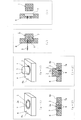
- FIG. 1 is a diagram for explaining a method of manufacturing a hybrid model according to an embodiment of the present invention, in which FIG. 1 (a) is an external perspective view showing a hybrid model, and FIGS. 1 (b) to 1 (h) are hybrid models. It is a figure for demonstrating this manufacturing method.
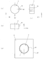
- FIG. 2 is a diagram for explaining a method for manufacturing a hybrid shaped article according to an embodiment of the present invention, in which FIG. 2 (a-1) is an external perspective view of a base plate to which the first shaped article is attached, and FIG. 2 (a-2) Is a longitudinal sectional view of the base plate to which the first modeled object is attached, FIG.
- FIG. 2 (b-1) is an external perspective view of the base plate to which the hybrid model is attached
- FIG. 2 (b-2) is a figure to which the hybrid model is attached
- FIG. 2C is a cross-sectional view of the base plate in a state where the hybrid model is being removed from the base plate
- FIG. 2D is a cross-sectional view of the state where the hybrid model is removed from the base plate. It is a figure which shows the modification of a 1st molded article
- Fig.3 (a) is a top view of a 1st molded article
- FIG.3 (b) is a 1st molded article seen from the arrow A1 direction of Fig.3 (a).
- FIG.3 (a) is a top view of a 1st molded article
- FIG.3 (b) is a 1st molded article seen from the arrow A1 direction of Fig.3 (a).
- FIG. 3C is a right side view of the first modeling unit viewed from the direction of the arrow A2 in FIG. 3A
- FIG. 3D is a plan view of the first modeling unit attached to the base plate.
- It is sectional drawing which shows the joint surface of the 1st molded article in another modification. It is a figure which shows the manufacturing process of the three-dimensional structure by the conventional powder sintering lamination method
- Fig.5 (a) is an external appearance perspective view of a modeling plate
- FIG.5 (b) is an external appearance perspective view of a modeling plate and a three-dimensional structure.
- FIG. 5 (c) is a perspective view for explaining an operation of separating the three-dimensional structure from the modeling plate
- FIG. 5 (d) is a perspective view showing a state in which the three-dimensional structure is separated from the modeling plate.
- FIGS. 1 and 2 are views for explaining a method of manufacturing a hybrid shaped article 1 according to an embodiment of the present invention.
- the second model 3 is bonded to the bonding surface (upper surface) 2 a of the first model 2.
- the first modeled object 2 is a columnar member formed in advance with high accuracy by cutting or the like.
- the second modeled object 3 is a cylindrical member having the same diameter as the first modeled object 2 and is formed on the joint surface 2a of the first modeled object 2 through the steps shown in FIGS. 1 (b) to (h). Joined and integrated.
- an iron-based material is used for the first modeled object 2.
- the base plate 6 attached to the lifting table 5 of the apparatus 4 is detachably attached in the first modeled object accommodation recess 7.
- the first modeling object accommodation recess 7 of the base plate 6 is a bottomed round hole, and the hole depth at which the joining surface (upper surface) 2a of the cylindrical first modeling object 2 slightly protrudes from the upper surface 6a of the base plate 6 is provided.
- the first model 2 is fixed to the bottom surface 7a with bolts 8.
- the base plate 6 is a metal flat plate member having a square planar shape.
- the powder sintering and laminating apparatus 4 applies the same kind of metal powder 10 as the first modeled object 2 on the joint surface 2 a of the first modeled object 2 attached to the base plate 6.
- a metal powder layer (powder layer) 12 having a desired thickness is formed on the joining surface 2a of the object 2 (powder layer forming step).
- the laser beam 14 is irradiated from the laser beam irradiation means 13 onto the metal powder layer 10 on the bonding surface 2 a of the first modeled object 2. And the boundary part of the joint surface 2a of the 1st molded article 2 and the metal powder layer 12 is melt
- the laser beam irradiation means 13 is controlled to operate based on input data such as three-dimensional CAD data, and can move with respect to the lifting table 5 (base plate 6). Moreover, the raising / lowering table 5 is comprised so that it can raise / lower along the Z-axis direction of FIG.1 (c), and is as much as the thickness of the metal powder layer 12 formed on the joining surface 2a of the 1st molded article 2. FIG. Only descends sequentially.
- the solidified layer forming step of forming the solidified layer 15 by baking and solidifying the portion of the metal powder layer 12 irradiated with the laser beam 14 is repeated.
- a second model 3 is formed as a three-dimensional model formed by laminating and integrating a plurality of solidified layers 15, and the second model 3 is bonded to the bonding surface 2 a of the first model 2.
- the hybrid model 1 in which the first model 2 and the second model 3 are integrated is formed.
- the hybrid shaped article 1 has the first shaping of the base plate 6 after the bolts 8 fixed to the base plate 6 are removed and separated from the base plate 6. It is taken out from the inside of the object housing recess 7 (fifth step).
- the hybrid shaped article 1 is subjected to necessary processing such as polishing, grinding, and heat treatment (annealing) in order to remove internal distortion caused by the heat of the laser beam 14 of the powder sintering laminating apparatus 4.
- necessary processing such as polishing, grinding, and heat treatment (annealing) in order to remove internal distortion caused by the heat of the laser beam 14 of the powder sintering laminating apparatus 4.
- the hybrid shaped article 1 is formed by forming the second shaped article 3 on the joint surface 2a of the first shaped article 2 by the powder sintering lamination method. After being done, it is separated from the base plate 6 simply by removing the bolt 8 that fixes the first modeled object 2 to the base plate 6. As a result, according to the method for manufacturing the hybrid shaped article 1 according to the present embodiment, the base plate 6 can be used as it is for the production of the next new hybrid shaped article 1.
- the uncut mark 103 of the three-dimensional structure 101 is removed from the modeling plate 100 by grinding or the like, and then the modeling plate 100 is used for manufacturing the next new three-dimensional structure 101. ),
- the cycle time of molding the three-dimensional structure (second structure 3) can be shortened, and the productivity of the three-dimensional structure (second structure 3) can be improved.
- the hybrid model 1 according to the present embodiment is cut in advance. By processing with high accuracy by processing or grinding, it is possible to engage with a fitting hole or the like of the mounted member with high accuracy.
- the three-dimensional shaped article 101 manufactured by the conventional powder sintering lamination method is related to the fitting hole or the like of the mounted member after the modeling work is completed. It is necessary to machine the part to be combined with high precision by cutting or grinding, but when the external shape is complicated, it cannot be chucked to the jig for processing, and post processing cannot be performed. There may be a problem that it is difficult to attach to a member to be attached which requires high-precision engagement.
- the first shaped article accommodation recess 7 is formed in the base plate 6, and the first shaped article 2 is accommodated in the first shaped article accommodation recess 7 of the base plate 6. Since the joining surface 2a of the first model 2 is slightly protruded from the upper surface 6a of the base plate 6, the base plate 6 is compared with the case where the first model 2 is fixed to the upper surface 6a of the base plate 6. The amount of the metal powder 10 to be supplied can be reduced, and the amount of the metal powder 10 used in one cycle of manufacturing the hybrid shaped article 1 can be saved.
- the manufacturing method of the hybrid shaped article 1 according to the present embodiment is a method of hybrid shaping after three-dimensional shaping by forming a mounting hole for a jig of a machine (for example, a composite lathe) in the first shaped article 2 in advance.
- the post-processing of the object 1 can be performed efficiently and accurately.
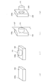
- FIG. 3 is a diagram illustrating a modified example of the first modeled object 2.
- 3A is a plan view of the first modeled object 2
- FIG. 3B is a front view of the first modeled object 2 viewed from the direction of the arrow A1 in FIG. 3A.
- FIG. 3C is a right side view of the first modeling unit 2 viewed from the direction of the arrow A2 in FIG. 3A
- FIG. 3D is a plan view of the first modeling unit 2 attached to the base plate 6. .
- the first model 2 is such that a part of the circumferential surface of the cylinder is scraped off in a virtual plane parallel to the YZ coordinate plane and perpendicular to the XY coordinate plane.
- a plane 16 (a plane serving as a reference for three-dimensional modeling) is formed.
- the first modeled object 2 is engaged with the first modeled object receiving recess 7 of the base plate 6, and then is attached to the base plate 6.
- the position of the flat surface 16 is adjusted so as to be parallel to one of the four side surfaces of the base plate 6 (mounting reference surface 17), and then finally tightened to the base plate 6 (strongly tightened and fixed).
- work which makes the plane 16 of the 1st molded article 2 and the attachment reference plane 17 of the baseplate 6 in parallel is performed using a dial gauge, a jig
- the first model 2 since the first model 2 according to this modification can make the plane 16 of the first model 2 and the mounting reference surface 17 of the base plate 6 parallel, the first model 2 is attached.
- the plane 16 of the first modeled object 2 (becomes a reference for three-dimensional modeling). The plane) can be positioned in the main scanning direction or the sub-scanning direction of the laser irradiation means 13.
- the powder-sintering laminating apparatus 4 using the first modeled object 2 and the base plate 6 attached with the first modeled object 2 according to this modification accurately forms the second modeled object 3 on the first modeled object 2.
- the manufacturing method of the hybrid shaped article 1 represents the joining surface 2a of the first shaped article 2 as a flat horizontal surface
- the present invention is not limited thereto, and a metal that enables the powder sintering lamination method to be performed.
- the bonding surface 2a may be a stepped surface (see FIG. 4A), an uneven surface (see FIG. 4B), or the like.
- the manufacturing method of the hybrid molded article 1 which concerns on the said embodiment makes the joint surface 2a of the 1st molded article 2 protrude slightly from the upper surface 6a of the base plate 6, it is not restricted to this,
- the bonding surface 2 a of the one shaped article 2 may be positioned on the same plane as the upper surface 6 a of the base plate 6.
- the manufacturing method of the hybrid molded article 1 which concerns on the said embodiment makes the joint surface 2a of the 1st molded article 2 protrude slightly from the upper surface 6a of the baseplate 6, it is not restricted to this, 3
- the joint surface 2a of the first modeled object 2 is positioned slightly retracted from the upper surface 6a of the base plate 6. May be.
- the manufacturing method of the hybrid molded article 1 which concerns on the said embodiment illustrated as making the 1st molded article 2 and the metal powder 10 into the same kind of iron-type material (for example, carbon steel), it is not restricted to this.
- the first modeled object 2 and the metal powder 10 may be made of a material other than the iron-based material (for example, a titanium alloy) or other metal material.
- the manufacturing method of the hybrid molded article 1 which concerns on the said embodiment illustrated as making the 1st molded article 2 and the metal powder 10 into the same kind of iron-type material (for example, carbon steel), it is not restricted to this.
- the first model 2 and the metal powder 10 are different metal materials (for example, the first model 2 is carbon steel and the metal powder 10 is a titanium alloy, or the first model 2 is a titanium alloy,
- the metal powder 10 may be carbon steel).
- the manufacturing method of the hybrid modeling thing 1 which concerns on the said embodiment illustrated as making the 1st modeling object 2 and the 2nd modeling object 3 into the same kind of metal (for example, carbon steel), it is not restricted to this.
- the first modeled object 2 and the second modeled object 3 may be formed of ceramics. That is, the manufacturing method of the hybrid model 1 according to the present invention replaces the first model 2 formed of a metal material with the first model 2 formed of ceramics, and replaces the metal powder 10 with the ceramic powder 10. May be.
- the hybrid shaped article 1 according to the present invention is not limited to the hybrid shaped article 1 according to the above-described embodiment, and may have various shapes such as a triangular prism, a quadrangular pillar, a hexagonal pillar other than a cylindrical one. .
- the hybrid model 1 according to the present invention is not limited to the hybrid model 1 according to the above-described embodiment, and the second model 3 may be formed in a shape different from that of the first model 2.
Abstract
[Problem] To improve productivity of three-dimensional shaped articles made by a powder sintering and layering method. [Solution] The present invention comprises: (1) a first step for detachably mounting a first shaped article 2 onto a base plate 6; (2) a second step for mounting the base plate 6, on which the first shaped article 2 has been detachably mounted, onto a vertically-moving table 5 of a powder sintering and layering device 4; (3) a third step for repeatedly performing work for forming, on the first shaped article 2, a powder layer 12 that can be bonded to the first shaped article 2, and work for irradiating the powder layer 12 with laser light to form a solid layer 15, to integrally form, on the first shaped article 2, a second shaped article 3 serving as a three-dimensional shaped article on which a plurality of solid layers 15 have been layered and integrated together, thus forming a hybrid shaped article 1 composed of the first shaped article 2 and the second shaped article 3; (4) a fourth step for taking the hybrid shaped article 1 and base plate 6 out from the vertically-moving table 5 of the powder sintering and layering device 4; and (5) a fifth step for taking the hybrid shaped article 1 out from the base plate 6.
Description
この発明は、第1造形物の上に、粉末焼結積層法を使用して第2造形物を一体に形成するハイブリッド造形物の製造方法、及びハイブリッド造形物に関するものである。
The present invention relates to a method for manufacturing a hybrid shaped article, in which a second shaped article is integrally formed on a first shaped article using a powder sintering lamination method, and a hybrid shaped article.
近年、粉末焼結積層法を使用して3次元造形物を形成する装置(粉末焼結積層装置)が広く普及している。この粉末焼結積層装置は、粉末材料タンクに収容してある金属粉末をブレードで金属製の造形プレート上に運び、ブレードで造形プレート上に所定の厚さの金属粉末層を形成した後、レーザー光照射手段から造形プレート上の金属粉末層の所定箇所にレーザー光を照射し、レーザー光が照射された部分の金属粉末層を焼き固める(固化させる)という工程を繰り返し行うことにより、複数の固化層が積層一体化した金属製の3次元造形物を造形プレート上に形成するようになっている(特許文献1参照)。
In recent years, an apparatus (powder sintering laminating apparatus) for forming a three-dimensional structure using a powder sintering laminating method has been widely used. This powder sintering and laminating apparatus carries metal powder contained in a powder material tank onto a metal modeling plate with a blade, forms a metal powder layer of a predetermined thickness on the modeling plate with a blade, and then lasers Multiple solidifications are performed by repeating the process of irradiating laser light to a predetermined part of the metal powder layer on the modeling plate from the light irradiation means and baking (solidifying) the metal powder layer in the portion irradiated with the laser light. A metal three-dimensional structure in which layers are laminated and integrated is formed on a modeling plate (see Patent Document 1).
このような粉末焼結積層法を使用して形成された金属製の3次元造形物は、レーザー光照射手段の操作に3次元CADソフトが使用されて、従来の射出成形や切削加工では作ることができなかった複雑な形状部分が容易に成形される。
A metal three-dimensional structure formed using such a powder-sintering lamination method is made by conventional injection molding or cutting, using three-dimensional CAD software for the operation of the laser light irradiation means. A complicated shape portion that could not be formed is easily formed.
従来の粉末焼結積層法によって金属製の3次元造形物を成形する場合、金属製の造形プレートと金属粉末層との境界部分がレーザー光で溶けて一体化する。そのため、図5に示すように、従来の粉末焼結積層法は、造形プレート100の上面100aに3次元造形物101を形成した後に(図5(a)~(b)参照)、一体化した造形プレート100と3次元造形物101を粉末焼結積層装置から取り外し、3次元造形物101と造形プレート100とを放電ワイヤ102又は切断具(例えば、金鋸)で切り離していた(図5(c)参照)。そして、3次元造形物101が切り離された造形プレート100は、図5(d)に示すように、表面(上面100a)に3次元造形物101の切り離し痕103が残るため、その3次元造形物101の切り離し痕103を研削加工等で除去し、新たな3次元造形物101の成形に備えるようになっていた。その結果、従来の粉末焼結積層法は、3次元造形物101の成形に着手した後に次の新たな3次元造形物101の成形に着手できるようになるまでに多くの時間(サイクルタイム)を要していた。
When a metal three-dimensional structure is formed by a conventional powder sintering lamination method, the boundary portion between the metal modeling plate and the metal powder layer is melted and integrated with the laser beam. Therefore, as shown in FIG. 5, the conventional powder sintering lamination method is integrated after the three-dimensional structure 101 is formed on the upper surface 100a of the modeling plate 100 (see FIGS. 5A to 5B). The modeling plate 100 and the three-dimensional model 101 are removed from the powder sintering and laminating apparatus, and the three-dimensional model 101 and the modeling plate 100 are separated by a discharge wire 102 or a cutting tool (for example, a gold saw) (FIG. 5C )reference). Then, as shown in FIG. 5D, the modeling plate 100 from which the three-dimensional structure 101 has been separated has the separation marks 103 of the three-dimensional structure 101 left on the surface (upper surface 100a). The separation trace 103 of 101 is removed by grinding or the like to prepare for forming a new three-dimensional structure 101. As a result, the conventional powder sintering lamination method takes a lot of time (cycle time) from the start of molding the three-dimensional structure 101 until the next new three-dimensional structure 101 can be molded. It was necessary.
そこで、本発明は、3次元造形物の成形のサイクルタイムを短縮でき、3次元造形物の生産性を向上させることができるハイブリッド造形物の製造方法及びハイブリッド造形物の提供を目的とする。
Therefore, an object of the present invention is to provide a method for manufacturing a hybrid model and a hybrid model that can shorten the cycle time of molding a three-dimensional model and improve the productivity of the three-dimensional model.
本発明のハイブリッド造形物1の製造方法は、以下の第1工程乃至第5工程を有している。
(1)第1工程
第1造形物2をベースプレート6に着脱可能に取り付ける。
(2)第2工程
前記第1造形物2を着脱可能に取り付けた前記ベースプレート6を粉末焼結積層装置4の昇降テーブル5に取り付ける。
(3)第3工程
前記第1造形物2と接合させることが可能な粉末層12を前記第1造形物2上に形成する作業と、前記粉末層12にレーザー光を照射して固化層15を形成する作業と、を繰り返し行い、
複数の前記固化層15が積層一体化された3次元造形物としての第2造形物3を前記第1造形物2に一体に形成し、前記第1造形物2と前記第2造形物3とからなるハイブリッド造形物1を成形する。
(4)第4工程
前記ハイブリッド造形物1及び前記ベースプレート6を前記粉末焼結積層装置4の前記昇降テーブル5から取り外す。
(5)第5工程
前記ベースプレート6から前記ハイブリッド造形物1を取り外す。 The manufacturing method of the hybrid shapedarticle 1 of the present invention includes the following first to fifth steps.
(1) 1st process The1st modeling thing 2 is attached to the baseplate 6 so that attachment or detachment is possible.
(2) Second Step Thebase plate 6 to which the first modeled object 2 is detachably attached is attached to the lifting table 5 of the powder sintered laminating apparatus 4.
(3) 3rd process The operation | work which forms thepowder layer 12 which can be joined to the said 1st molded article 2 on the said 1st molded article 2, and the solidified layer 15 by irradiating the said powder layer 12 with a laser beam The process of forming
Asecond model 3 as a three-dimensional modeled object in which a plurality of the solidified layers 15 are laminated and integrated is formed integrally with the first model 2, and the first model 2 and the second model 3 are formed. A hybrid shaped article 1 is formed.
(4) 4th process The said hybrid moldedarticle 1 and the said base plate 6 are removed from the said raising / lowering table 5 of the said powder sintering lamination apparatus 4. FIG.
(5) Fifth step The hybridshaped article 1 is removed from the base plate 6.
(1)第1工程
第1造形物2をベースプレート6に着脱可能に取り付ける。
(2)第2工程
前記第1造形物2を着脱可能に取り付けた前記ベースプレート6を粉末焼結積層装置4の昇降テーブル5に取り付ける。
(3)第3工程
前記第1造形物2と接合させることが可能な粉末層12を前記第1造形物2上に形成する作業と、前記粉末層12にレーザー光を照射して固化層15を形成する作業と、を繰り返し行い、
複数の前記固化層15が積層一体化された3次元造形物としての第2造形物3を前記第1造形物2に一体に形成し、前記第1造形物2と前記第2造形物3とからなるハイブリッド造形物1を成形する。
(4)第4工程
前記ハイブリッド造形物1及び前記ベースプレート6を前記粉末焼結積層装置4の前記昇降テーブル5から取り外す。
(5)第5工程
前記ベースプレート6から前記ハイブリッド造形物1を取り外す。 The manufacturing method of the hybrid shaped
(1) 1st process The
(2) Second Step The
(3) 3rd process The operation | work which forms the
A
(4) 4th process The said hybrid molded
(5) Fifth step The hybrid
また、本発明は、第1造形物2の接合面2aに、3次元造形物である第2造形物3が粉末焼結積層法によって接合されたハイブリッド造形物1に関するものである。
The present invention also relates to the hybrid model 1 in which the second model 3 that is a three-dimensional model is joined to the joint surface 2a of the first model 2 by the powder sintering lamination method.
本発明に係るハイブリッド造形物の製造方法によれば、ハイブリッド造形物は、第1造形物上に第2造形物が粉末焼結積層法によって造形された後、第1造形物をベースプレートから取り外すだけで、ベースプレートから分離される。その結果、本実施形態に係るハイブリッド造形物1の製造方法によれば、ベースプレートを次の新たなハイブリッド造形物の製造にそのまま利用できるため、従来例と比較して、3次元造形物(第2造形物)の成形のサイクルタイムを短縮でき、3次元造形物(第2造形物)の生産性を向上させることができる。
According to the method for manufacturing a hybrid model according to the present invention, the hybrid model only removes the first model from the base plate after the second model is modeled on the first model by the powder sintering lamination method. And separated from the base plate. As a result, according to the method for manufacturing the hybrid shaped article 1 according to the present embodiment, the base plate can be used as it is for the production of the next new hybrid shaped article. The molding cycle time of the (modeled object) can be shortened, and the productivity of the three-dimensional modeled object (second modeled object) can be improved.
以下、本発明の実施形態を図面に基づき詳述する。
Hereinafter, embodiments of the present invention will be described in detail with reference to the drawings.
図1及び図2は、本発明の実施形態に係るハイブリッド造形物1の製造方法を説明するための図である。図1(a)に示すハイブリッド造形物1は、第1造形物2の接合面(上面)2aに第2造形物3が接合されている。第1造形物2は、予め切削加工等によって高精度に形成された円柱状の部材である。また、第2造形物3は、第1造形物2と同径で且つ円柱状の部材であり、図1(b)~(h)の各工程を経て第1造形物2の接合面2aに接合・一体化される。なお、第1造形物2は、例えば、鉄系材料(炭素鋼等)が使用される。
1 and 2 are views for explaining a method of manufacturing a hybrid shaped article 1 according to an embodiment of the present invention. In the hybrid model 1 shown in FIG. 1A, the second model 3 is bonded to the bonding surface (upper surface) 2 a of the first model 2. The first modeled object 2 is a columnar member formed in advance with high accuracy by cutting or the like. The second modeled object 3 is a cylindrical member having the same diameter as the first modeled object 2 and is formed on the joint surface 2a of the first modeled object 2 through the steps shown in FIGS. 1 (b) to (h). Joined and integrated. For example, an iron-based material (carbon steel or the like) is used for the first modeled object 2.
(第1工程)
先ず、図1(b)、図1(c)、図2(a-1)、及び図2(a-2)に示すように、予め加工された第1造形物2は、粉末焼結積層装置4の昇降テーブル5に取り付けられるベースプレート6の第1造形物収容凹所7内に着脱可能に取り付けられる。ベースプレート6の第1造形物収容凹所7は、有底の丸穴であり、円柱状の第1造形物2の接合面(上面)2aがベースプレート6の上面6aよりも僅かに出っ張る穴深さに形成され、第1造形物2が底面7aにボルト8で固定されている。なお、ベースプレート6は、平面形状が四角形状の金属製の平板部材である。 (First step)
First, as shown in FIG. 1 (b), FIG. 1 (c), FIG. 2 (a-1), and FIG. Thebase plate 6 attached to the lifting table 5 of the apparatus 4 is detachably attached in the first modeled object accommodation recess 7. The first modeling object accommodation recess 7 of the base plate 6 is a bottomed round hole, and the hole depth at which the joining surface (upper surface) 2a of the cylindrical first modeling object 2 slightly protrudes from the upper surface 6a of the base plate 6 is provided. The first model 2 is fixed to the bottom surface 7a with bolts 8. The base plate 6 is a metal flat plate member having a square planar shape.
先ず、図1(b)、図1(c)、図2(a-1)、及び図2(a-2)に示すように、予め加工された第1造形物2は、粉末焼結積層装置4の昇降テーブル5に取り付けられるベースプレート6の第1造形物収容凹所7内に着脱可能に取り付けられる。ベースプレート6の第1造形物収容凹所7は、有底の丸穴であり、円柱状の第1造形物2の接合面(上面)2aがベースプレート6の上面6aよりも僅かに出っ張る穴深さに形成され、第1造形物2が底面7aにボルト8で固定されている。なお、ベースプレート6は、平面形状が四角形状の金属製の平板部材である。 (First step)
First, as shown in FIG. 1 (b), FIG. 1 (c), FIG. 2 (a-1), and FIG. The
(第2工程)
次に、図1(c)に示すように、第1造形物2が取り付けられたベースプレート6は、粉末焼結積層装置4の昇降テーブル5上に固定される(第2工程)。 (Second step)
Next, as shown in FIG.1 (c), thebaseplate 6 with which the 1st molded article 2 was attached is fixed on the raising / lowering table 5 of the powder sintering lamination apparatus 4 (2nd process).
次に、図1(c)に示すように、第1造形物2が取り付けられたベースプレート6は、粉末焼結積層装置4の昇降テーブル5上に固定される(第2工程)。 (Second step)
Next, as shown in FIG.1 (c), the
(第3工程)
次に、図1(c)に示すように、粉末焼結積層装置4は、ベースプレート6に取り付けられた第1造形物2の接合面2a上に第1造形物2と同種の金属粉末10を供給し、第1造形物2の接合面2a上の金属粉末10を水平方向(図1(c)のX軸に沿った方向)に移動するブレード11(又はローラ)によって均し、第1造形物2の接合面2a上に所望厚さの金属粉末層(粉末層)12を形成する(粉末層形成工程部分)。 (Third step)
Next, as shown in FIG. 1 (c), the powder sintering and laminatingapparatus 4 applies the same kind of metal powder 10 as the first modeled object 2 on the joint surface 2 a of the first modeled object 2 attached to the base plate 6. Supply and level the metal powder 10 on the joint surface 2a of the first model 2 with the blade 11 (or roller) moving in the horizontal direction (the direction along the X axis in FIG. 1C), A metal powder layer (powder layer) 12 having a desired thickness is formed on the joining surface 2a of the object 2 (powder layer forming step).
次に、図1(c)に示すように、粉末焼結積層装置4は、ベースプレート6に取り付けられた第1造形物2の接合面2a上に第1造形物2と同種の金属粉末10を供給し、第1造形物2の接合面2a上の金属粉末10を水平方向(図1(c)のX軸に沿った方向)に移動するブレード11(又はローラ)によって均し、第1造形物2の接合面2a上に所望厚さの金属粉末層(粉末層)12を形成する(粉末層形成工程部分)。 (Third step)
Next, as shown in FIG. 1 (c), the powder sintering and laminating
次に、図1(c)に示すように、第1造形物2の接合面2a上の金属粉末層10には、レーザー光照射手段13からレーザー光14が照射される。そして、第1造形物2の接合面2aと金属粉末層12との境界部分は、レーザー光14で溶かされて一体化させられる。また、図1(d)に示すように、第1造形物2の接合面2a上の金属粉末層12は、レーザー光14で焼き固められて、固化層15になる(固化層形成工程部分)。なお、レーザー光照射手段13は、3次元CADデータ等の入力データに基づいて作動制御され、昇降テーブル5(ベースプレート6)に対して移動できるようになっている。また、昇降テーブル5は、図1(c)のZ軸方向に沿って昇降できるように構成されており、第1造形物2の接合面2a上に形成される金属粉末層12の厚さ分だけ順次降下するようになっている。
Next, as shown in FIG. 1 (c), the laser beam 14 is irradiated from the laser beam irradiation means 13 onto the metal powder layer 10 on the bonding surface 2 a of the first modeled object 2. And the boundary part of the joint surface 2a of the 1st molded article 2 and the metal powder layer 12 is melt | dissolved by the laser beam 14, and is integrated. Moreover, as shown in FIG.1 (d), the metal powder layer 12 on the joining surface 2a of the 1st molded article 2 is baked and hardened with the laser beam 14, and becomes the solidified layer 15 (solidified layer formation process part). . The laser beam irradiation means 13 is controlled to operate based on input data such as three-dimensional CAD data, and can move with respect to the lifting table 5 (base plate 6). Moreover, the raising / lowering table 5 is comprised so that it can raise / lower along the Z-axis direction of FIG.1 (c), and is as much as the thickness of the metal powder layer 12 formed on the joining surface 2a of the 1st molded article 2. FIG. Only descends sequentially.
次に、図1(e)~(h)に示すように、第1造形物2の接合面2a上に金属粉末層12を形成する粉末層形成工程部分と、金属粉末層12にレーザー光14を照射し、レーザー光14が照射された部分の金属粉末層12を焼き固めて固化層15を形成する固化層形成工程部分と、を繰り返し行う。これによって、複数の固化層15を積層一体化してなる3次元造形物としての第2造形物3が形成されると共に、この第2造形物3が第1造形物2の接合面2aに接合され、第1造形物2と第2造形物3が一体化されたハイブリッド造形物1が形成される。
Next, as shown in FIGS. 1E to 1H, a powder layer forming step for forming the metal powder layer 12 on the bonding surface 2a of the first modeled object 2, and a laser beam 14 applied to the metal powder layer 12. The solidified layer forming step of forming the solidified layer 15 by baking and solidifying the portion of the metal powder layer 12 irradiated with the laser beam 14 is repeated. As a result, a second model 3 is formed as a three-dimensional model formed by laminating and integrating a plurality of solidified layers 15, and the second model 3 is bonded to the bonding surface 2 a of the first model 2. The hybrid model 1 in which the first model 2 and the second model 3 are integrated is formed.
(第4工程)
次に、図2(b-1)及び図2(b-2)に示すように、ベースプレート6及びハイブリッド造形物1は、粉末焼結積層装置4の昇降テーブル5から取り外される(第4工程)。 (4th process)
Next, as shown in FIGS. 2 (b-1) and 2 (b-2), thebase plate 6 and the hybrid shaped article 1 are removed from the lifting table 5 of the powder sintering and laminating apparatus 4 (fourth step). .
次に、図2(b-1)及び図2(b-2)に示すように、ベースプレート6及びハイブリッド造形物1は、粉末焼結積層装置4の昇降テーブル5から取り外される(第4工程)。 (4th process)
Next, as shown in FIGS. 2 (b-1) and 2 (b-2), the
(第5工程)
次に、図2(c)及び図2(d)に示すように、ハイブリッド造形物1は、ベースプレート6に固定したボルト8が取り外され、ベースプレート6から分離された後、ベースプレート6の第1造形物収容凹所7内から取り出される(第5工程)。 (5th process)
Next, as shown in FIGS. 2 (c) and 2 (d), the hybrid shapedarticle 1 has the first shaping of the base plate 6 after the bolts 8 fixed to the base plate 6 are removed and separated from the base plate 6. It is taken out from the inside of the object housing recess 7 (fifth step).
次に、図2(c)及び図2(d)に示すように、ハイブリッド造形物1は、ベースプレート6に固定したボルト8が取り外され、ベースプレート6から分離された後、ベースプレート6の第1造形物収容凹所7内から取り出される(第5工程)。 (5th process)
Next, as shown in FIGS. 2 (c) and 2 (d), the hybrid shaped
次に、ハイブリッド造形物1は、粉末焼結積層装置4のレーザー光14の熱によって生じた内部歪みを取り除くため、研磨、研削、熱処理(焼鈍し)等の必要な処理が施される。
Next, the hybrid shaped article 1 is subjected to necessary processing such as polishing, grinding, and heat treatment (annealing) in order to remove internal distortion caused by the heat of the laser beam 14 of the powder sintering laminating apparatus 4.
(本実施形態の効果)
以上のような本実施形態に係るハイブリッド造形物1の製造方法によれば、ハイブリッド造形物1は、第1造形物2の接合面2a上に第2造形物3が粉末焼結積層法によって造形された後、第1造形物2をベースプレート6に固定するボルト8を取り外すだけで、ベースプレート6から分離される。その結果、本実施形態に係るハイブリッド造形物1の製造方法によれば、ベースプレート6を次の新たなハイブリッド造形物1の製造にそのまま利用できるため、従来例(造形プレート100から3次元造形物101を切断して分離した後、3次元造形物101の切り残し痕103を造形プレート100上から研削加工等で取り除き、その後、造形プレート100を次の新たな3次元造形物101の製造に利用する)と比較し、3次元造形物(第2造形物3)の成形のサイクルタイムを短縮でき、3次元造形物(第2造形物3)の生産性を向上させることができる。 (Effect of this embodiment)
According to the manufacturing method of the hybrid shapedarticle 1 according to the present embodiment as described above, the hybrid shaped article 1 is formed by forming the second shaped article 3 on the joint surface 2a of the first shaped article 2 by the powder sintering lamination method. After being done, it is separated from the base plate 6 simply by removing the bolt 8 that fixes the first modeled object 2 to the base plate 6. As a result, according to the method for manufacturing the hybrid shaped article 1 according to the present embodiment, the base plate 6 can be used as it is for the production of the next new hybrid shaped article 1. After cutting and separating, the uncut mark 103 of the three-dimensional structure 101 is removed from the modeling plate 100 by grinding or the like, and then the modeling plate 100 is used for manufacturing the next new three-dimensional structure 101. ), The cycle time of molding the three-dimensional structure (second structure 3) can be shortened, and the productivity of the three-dimensional structure (second structure 3) can be improved.
以上のような本実施形態に係るハイブリッド造形物1の製造方法によれば、ハイブリッド造形物1は、第1造形物2の接合面2a上に第2造形物3が粉末焼結積層法によって造形された後、第1造形物2をベースプレート6に固定するボルト8を取り外すだけで、ベースプレート6から分離される。その結果、本実施形態に係るハイブリッド造形物1の製造方法によれば、ベースプレート6を次の新たなハイブリッド造形物1の製造にそのまま利用できるため、従来例(造形プレート100から3次元造形物101を切断して分離した後、3次元造形物101の切り残し痕103を造形プレート100上から研削加工等で取り除き、その後、造形プレート100を次の新たな3次元造形物101の製造に利用する)と比較し、3次元造形物(第2造形物3)の成形のサイクルタイムを短縮でき、3次元造形物(第2造形物3)の生産性を向上させることができる。 (Effect of this embodiment)
According to the manufacturing method of the hybrid shaped
本実施形態に係るハイブリッド造形物1は、第1造形物2が被取付部材(図示せず)の嵌合穴等に高精度で係合させる必要がある場合、第1造形物2を予め切削加工や研削加工で高精度に加工しておくことにより、被取付部材の嵌合穴等に高精度に係合させることができる。このような本実施形態に係るハイブリッド造形物1に対し、従来の粉末焼結積層法によって製造された3次元造形物101は、造形作業が終了した後に、被取付部材の嵌合穴等に係合される部分を切削加工又は研削加工で高精度に加工する必要があるが、外観形状が複雑な場合に、加工のための治具へのチャッキングができず、後加工ができないために、高精度の係合を求められる被取付部材への取り付けが困難になるという問題を生じることがある。
When the first model 2 needs to be engaged with a fitting hole or the like of a member to be attached (not shown) with high accuracy, the hybrid model 1 according to the present embodiment is cut in advance. By processing with high accuracy by processing or grinding, it is possible to engage with a fitting hole or the like of the mounted member with high accuracy. In contrast to the hybrid shaped article 1 according to the present embodiment, the three-dimensional shaped article 101 manufactured by the conventional powder sintering lamination method is related to the fitting hole or the like of the mounted member after the modeling work is completed. It is necessary to machine the part to be combined with high precision by cutting or grinding, but when the external shape is complicated, it cannot be chucked to the jig for processing, and post processing cannot be performed. There may be a problem that it is difficult to attach to a member to be attached which requires high-precision engagement.
本実施形態に係るハイブリッド造形物1の製造方法は、ベースプレート6に第1造形物収容凹所7を形成し、第1造形物2をベースプレート6の第1造形物収容凹所7内に収容し、第1造形物2の接合面2aをベースプレート6の上面6aよりも僅かに出っ張らせるようになっているため、ベースプレート6の上面6aに第1造形物2を固定する場合と比較し、ベースプレート6上に供給する金属粉末10の量を少なくすることができ、ハイブリッド造形物1の製造の1サイクルで使用する金属粉末10の量を節約することが可能になる。
In the manufacturing method of the hybrid shaped article 1 according to the present embodiment, the first shaped article accommodation recess 7 is formed in the base plate 6, and the first shaped article 2 is accommodated in the first shaped article accommodation recess 7 of the base plate 6. Since the joining surface 2a of the first model 2 is slightly protruded from the upper surface 6a of the base plate 6, the base plate 6 is compared with the case where the first model 2 is fixed to the upper surface 6a of the base plate 6. The amount of the metal powder 10 to be supplied can be reduced, and the amount of the metal powder 10 used in one cycle of manufacturing the hybrid shaped article 1 can be saved.
本実施形態に係るハイブリッド造形物1の製造方法は、機械(例えば、複合旋盤)の治具への取付穴を第1造形物2に予め形成しておくことにより、3次元造形後におけるハイブリッド造形物1の後加工を効率的に且つ正確に行うことが可能になる。
The manufacturing method of the hybrid shaped article 1 according to the present embodiment is a method of hybrid shaping after three-dimensional shaping by forming a mounting hole for a jig of a machine (for example, a composite lathe) in the first shaped article 2 in advance. The post-processing of the object 1 can be performed efficiently and accurately.
(変形例1)
図3は、第1造形物2の変形例を示す図である。なお、図3(a)は第1造形物2の平面図であり、図3(b)は図3(a)の矢印A1方向から見た第1造形物2の正面図であり、図3(c)は図3(a)の矢印A2方向から見た第1造形部2の右側面図であり、図3(d)はベースプレート6に取り付けられた第1造形部2の平面図である。 (Modification 1)
FIG. 3 is a diagram illustrating a modified example of the first modeledobject 2. 3A is a plan view of the first modeled object 2, and FIG. 3B is a front view of the first modeled object 2 viewed from the direction of the arrow A1 in FIG. 3A. FIG. 3C is a right side view of the first modeling unit 2 viewed from the direction of the arrow A2 in FIG. 3A, and FIG. 3D is a plan view of the first modeling unit 2 attached to the base plate 6. .
図3は、第1造形物2の変形例を示す図である。なお、図3(a)は第1造形物2の平面図であり、図3(b)は図3(a)の矢印A1方向から見た第1造形物2の正面図であり、図3(c)は図3(a)の矢印A2方向から見た第1造形部2の右側面図であり、図3(d)はベースプレート6に取り付けられた第1造形部2の平面図である。 (Modification 1)
FIG. 3 is a diagram illustrating a modified example of the first modeled
図3に示すように、第1造形物2は、円柱の周面の一部をY-Z座標面と平行な仮想平面で且つX-Y座標面に直交する仮想平面で削り取られたような平面16(3次元造形の基準となる平面)が形成されている。そして、この第1造形物2は、図3(d)及び図2(a-2)に示すように、ベースプレート6の第1造形物収容凹所7内に係合された後、ベースプレート6にボルト8で仮締めされ、平面16がベースプレート6の4側面のうちの1側面(取付基準面17)と平行になるように位置調整された後、ベースプレート6に本締めされる(強く締め付け固定される)。なお、第1造形物2の平面16とベースプレート6の取付基準面17とを平行にする作業は、例えば、フライス盤のベッド上において、ダイヤルゲージ、治具等を使用して行われる。
As shown in FIG. 3, the first model 2 is such that a part of the circumferential surface of the cylinder is scraped off in a virtual plane parallel to the YZ coordinate plane and perpendicular to the XY coordinate plane. A plane 16 (a plane serving as a reference for three-dimensional modeling) is formed. Then, as shown in FIGS. 3 (d) and 2 (a-2), the first modeled object 2 is engaged with the first modeled object receiving recess 7 of the base plate 6, and then is attached to the base plate 6. After being temporarily tightened with the bolts 8, the position of the flat surface 16 is adjusted so as to be parallel to one of the four side surfaces of the base plate 6 (mounting reference surface 17), and then finally tightened to the base plate 6 (strongly tightened and fixed). ) In addition, the operation | work which makes the plane 16 of the 1st molded article 2 and the attachment reference plane 17 of the baseplate 6 in parallel is performed using a dial gauge, a jig | tool, etc. on the bed of a milling machine, for example.
本変形例に係る第1造形物2は、上述のように、第1造形物2の平面16とベースプレート6の取付基準面17とを平行にすることができるため、第1造形物2が取り付けられたベースプレート6の取付基準面17を粉末焼結積層装置4のレーザー照射手段13の主走査方向又は副走査方向に合わせるだけで、第1造形物2の平面16(3次元造形の基準となる平面)をレーザー照射手段13の主走査方向又は副走査方向に位置決めすることが可能になる。そのため、本変形例に係る第1造形物2及びこの第1造形物2を取り付けたベースプレート6を使用する粉末焼結積層装置4は、第1造形物2に対する第2造形物3の造形を正確に行うことが可能になる(例えば、第1造形物2に予め形成された穴と第2造形物3(3次元造形物)に形成された穴とを正確に位置合わせすることが可能になる)。
As described above, since the first model 2 according to this modification can make the plane 16 of the first model 2 and the mounting reference surface 17 of the base plate 6 parallel, the first model 2 is attached. By simply matching the mounting reference surface 17 of the base plate 6 to the main scanning direction or sub-scanning direction of the laser irradiation means 13 of the powder sintering and laminating apparatus 4, the plane 16 of the first modeled object 2 (becomes a reference for three-dimensional modeling). The plane) can be positioned in the main scanning direction or the sub-scanning direction of the laser irradiation means 13. Therefore, the powder-sintering laminating apparatus 4 using the first modeled object 2 and the base plate 6 attached with the first modeled object 2 according to this modification accurately forms the second modeled object 3 on the first modeled object 2. (For example, it is possible to accurately align a hole formed in advance in the first model 2 and a hole formed in the second model 3 (three-dimensional model). ).
(その他の変形例)
上記実施形態に係るハイブリッド造形物1の製造方法は、第1造形物2の接合面2aを平坦な水平面で表しているが、これに限られず、粉末焼結積層法の実施を可能にする金属粉末層12を形成することができる限り、接合面2aをステップ状面(図4(a)参照)、凹凸面(図4(b)参照)等にしてもよい。 (Other variations)
Although the manufacturing method of the hybrid shapedarticle 1 according to the above-described embodiment represents the joining surface 2a of the first shaped article 2 as a flat horizontal surface, the present invention is not limited thereto, and a metal that enables the powder sintering lamination method to be performed. As long as the powder layer 12 can be formed, the bonding surface 2a may be a stepped surface (see FIG. 4A), an uneven surface (see FIG. 4B), or the like.
上記実施形態に係るハイブリッド造形物1の製造方法は、第1造形物2の接合面2aを平坦な水平面で表しているが、これに限られず、粉末焼結積層法の実施を可能にする金属粉末層12を形成することができる限り、接合面2aをステップ状面(図4(a)参照)、凹凸面(図4(b)参照)等にしてもよい。 (Other variations)
Although the manufacturing method of the hybrid shaped
また、上記実施形態に係るハイブリッド造形物1の製造方法は、第1造形物2の接合面2aをベースプレート6の上面6aよりも僅かに出っ張らせるようになっているが、これに限られず、第1造形物2の接合面2aをベースプレート6の上面6aと同一の平面上に位置するようにしてもよい。
Moreover, although the manufacturing method of the hybrid molded article 1 which concerns on the said embodiment makes the joint surface 2a of the 1st molded article 2 protrude slightly from the upper surface 6a of the base plate 6, it is not restricted to this, The bonding surface 2 a of the one shaped article 2 may be positioned on the same plane as the upper surface 6 a of the base plate 6.
また、上記実施形態に係るハイブリッド造形物1の製造方法は、第1造形物2の接合面2aをベースプレート6の上面6aよりも僅かに出っ張らせるようになっているが、これに限られず、3次元造形に適した金属粉末層12を第1造形物2の接合面2a上に形成できる限り、第1造形物2の接合面2aをベースプレート6の上面6aよりも僅かに引っ込んで位置するようにしてもよい。
Moreover, although the manufacturing method of the hybrid molded article 1 which concerns on the said embodiment makes the joint surface 2a of the 1st molded article 2 protrude slightly from the upper surface 6a of the baseplate 6, it is not restricted to this, 3 As long as the metal powder layer 12 suitable for three-dimensional modeling can be formed on the joint surface 2a of the first modeled object 2, the joint surface 2a of the first modeled object 2 is positioned slightly retracted from the upper surface 6a of the base plate 6. May be.
また、上記実施形態に係るハイブリッド造形物1の製造方法は、第1造形物2と金属粉末10とを同種の鉄系材料(例えば、炭素鋼)にするように例示したが、これに限られず、第1造形物2と金属粉末10とを鉄系材料以外の材料(例えば、チタン合金)やその他の金属材料にしてもよい。
Moreover, although the manufacturing method of the hybrid molded article 1 which concerns on the said embodiment illustrated as making the 1st molded article 2 and the metal powder 10 into the same kind of iron-type material (for example, carbon steel), it is not restricted to this. The first modeled object 2 and the metal powder 10 may be made of a material other than the iron-based material (for example, a titanium alloy) or other metal material.
また、上記実施形態に係るハイブリッド造形物1の製造方法は、第1造形物2と金属粉末10とを同種の鉄系材料(例えば、炭素鋼)にするように例示したが、これに限られず、第1造形物2と金属粉末10とを異種の金属材料(例えば、第1造形物2を炭素鋼とし、金属粉末10をチタン合金とするか、又は第1造形物2をチタン合金とし、金属粉末10を炭素鋼とする)にしてもよい。
Moreover, although the manufacturing method of the hybrid molded article 1 which concerns on the said embodiment illustrated as making the 1st molded article 2 and the metal powder 10 into the same kind of iron-type material (for example, carbon steel), it is not restricted to this. The first model 2 and the metal powder 10 are different metal materials (for example, the first model 2 is carbon steel and the metal powder 10 is a titanium alloy, or the first model 2 is a titanium alloy, The metal powder 10 may be carbon steel).
また、上記実施形態に係るハイブリッド造形物1の製造方法は、第1造形物2と第2造形物3とを同一種の金属(例えば、炭素鋼)にするように例示したが、これに限られず、第1造形物2と第2造形物3とをセラミックスで形成するようにしてもよい。すなわち、本発明に係るハイブリッド造形物1の製造方法は、金属材料で形成された第1造形物2をセラミックスで形成された第1造形物2に置き換え、金属粉末10をセラミックスの粉末10に置き換えてもよい。
Moreover, although the manufacturing method of the hybrid modeling thing 1 which concerns on the said embodiment illustrated as making the 1st modeling object 2 and the 2nd modeling object 3 into the same kind of metal (for example, carbon steel), it is not restricted to this. Instead, the first modeled object 2 and the second modeled object 3 may be formed of ceramics. That is, the manufacturing method of the hybrid model 1 according to the present invention replaces the first model 2 formed of a metal material with the first model 2 formed of ceramics, and replaces the metal powder 10 with the ceramic powder 10. May be.
また、本発明に係るハイブリッド造形物1は、上記実施形態に係るハイブリッド造形物1に限定されず、円柱状のもの以外の三角柱、四角柱、六角柱等の様々な形状のものにしてもよい。
Moreover, the hybrid shaped article 1 according to the present invention is not limited to the hybrid shaped article 1 according to the above-described embodiment, and may have various shapes such as a triangular prism, a quadrangular pillar, a hexagonal pillar other than a cylindrical one. .
また、本発明に係るハイブリッド造形物1は、上記実施形態に係るハイブリッド造形物1に限定されず、第2造形物3を第1造形物2と異なる形状に形成するようにしてもよい。
Further, the hybrid model 1 according to the present invention is not limited to the hybrid model 1 according to the above-described embodiment, and the second model 3 may be formed in a shape different from that of the first model 2.
1……ハイブリッド造形物、2……第1造形物、3……第2造形物、4……粉末焼結積層装置、5……昇降テーブル、6……ベースプレート、12……金属粉末層(粉末層)、15……固化層
DESCRIPTION OF SYMBOLS 1 ... Hybrid molded object, 2 ... 1st molded object, 3 ... 2nd molded object, 4 ... Powder sintering lamination apparatus, 5 ... Elevating table, 6 ... Base plate, 12 ... Metal powder layer ( Powder layer), 15 ... Solidified layer
Claims (5)
- (1)第1工程
第1造形物をベースプレートに着脱可能に取り付ける第1工程と、
(2)第2工程
前記第1造形物を着脱可能に取り付けた前記ベースプレートを粉末焼結積層装置の昇降テーブルに取り付ける第2工程と、
(3)第3工程
前記第1造形物と接合させることが可能な粉末層を前記第1造形物上に形成する作業と、前記粉末層にレーザー光を照射して固化層を形成する作業と、を繰り返し行い、
複数の前記固化層が積層一体化された3次元造形物としての第2造形物を前記第1造形物に一体に形成し、前記第1造形物と前記第2造形物とからなるハイブリッド造形物を成形する第3工程と、
(4)第4工程
前記ハイブリッド造形物及び前記ベースプレートを前記粉末焼結積層装置の前記昇降テーブルから取り外す第4工程と、
(5)第5工程
前記ベースプレートから前記ハイブリッド造形物を取り外す第5工程と、
を有することを特徴とするハイブリッド造形物の製造方法。 (1) 1st process The 1st process of attaching a 1st modeling thing to a base plate so that attachment or detachment is possible,
(2) 2nd process The 2nd process of attaching the said base plate which attached the said 1st modeling thing removably to the raising / lowering table of a powder sintering lamination apparatus,
(3) 3rd process The operation | work which forms the powder layer which can be joined with the said 1st modeling object on the said 1st modeling object, The operation | work which irradiates a laser beam to the said powder layer, and forms a solidified layer , Repeatedly
A second modeled object as a three-dimensional modeled object in which a plurality of the solidified layers are laminated and integrated is integrally formed on the first modeled object, and a hybrid modeled article composed of the first modeled object and the second modeled object. A third step of molding
(4) 4th process The 4th process which removes the said hybrid modeling thing and the said base plate from the said raising / lowering table of the said powder sintering lamination apparatus,
(5) Fifth step A fifth step of removing the hybrid model from the base plate;
The manufacturing method of the hybrid molded article characterized by having. - 前記第1造形物は、ベースプレートに形成された第1造形物収容凹所内に収容され、
前記第1造形物収容凹所内に収容された前記第1造形物の上面には、前記固化層を形成するのに適した厚さの前記粉末層が形成される、
ことを特徴とする請求項1に記載のハイブリッド造形物の製造方法。 The first modeled object is accommodated in a first modeled object accommodation recess formed in the base plate,
The powder layer having a thickness suitable for forming the solidified layer is formed on the upper surface of the first modeled object housed in the first modeled object housing recess.
The method for manufacturing a hybrid shaped article according to claim 1. - 前記粉末層は、前記ベースプレートと同種金属の粉末で形成される、
ことを特徴とする請求項1又は2に記載のハイブリッド造形物の製造方法。 The powder layer is formed of a powder of the same metal as the base plate.
The method for producing a hybrid shaped article according to claim 1 or 2, wherein: - 前記粉末は、鋼の粉末であり、
前記ハイブリッド造形物は、前記ベースプレートから取り外された後、焼鈍しが行われる、
ことを特徴とする請求項3に記載のハイブリッド造形物の製造方法。 The powder is steel powder;
The hybrid shaped article is annealed after being removed from the base plate.
The method for producing a hybrid shaped article according to claim 3. - 第1造形物の接合面に、3次元造形物である第2造形物が粉末焼結積層法によって接合されてなる、ことを特徴とするハイブリッド造形物。 A hybrid shaped article, wherein a second shaped article, which is a three-dimensional shaped article, is joined to the joint surface of the first shaped article by a powder sintering lamination method.
Applications Claiming Priority (2)
| Application Number | Priority Date | Filing Date | Title |
|---|---|---|---|
| JP2016-095723 | 2016-05-12 | ||
| JP2016095723A JP6691429B2 (en) | 2016-05-12 | 2016-05-12 | Method for manufacturing hybrid shaped article and hybrid shaped article |
Publications (1)
| Publication Number | Publication Date |
|---|---|
| WO2017195773A1 true WO2017195773A1 (en) | 2017-11-16 |
Family
ID=60266642
Family Applications (1)
| Application Number | Title | Priority Date | Filing Date |
|---|---|---|---|
| PCT/JP2017/017536 WO2017195773A1 (en) | 2016-05-12 | 2017-05-09 | Method for manufacturing hybrid shaped article, and hybrid shaped article |
Country Status (2)
| Country | Link |
|---|---|
| JP (1) | JP6691429B2 (en) |
| WO (1) | WO2017195773A1 (en) |
Cited By (2)
| Publication number | Priority date | Publication date | Assignee | Title |
|---|---|---|---|---|
| CN110281683A (en) * | 2019-07-18 | 2019-09-27 | 广州番禺职业技术学院 | A kind of artwork Ornament production method of ceramic inserts metal |
| CN114103098A (en) * | 2020-08-27 | 2022-03-01 | 精工爱普生株式会社 | Method for manufacturing mold and mold |
Families Citing this family (2)
| Publication number | Priority date | Publication date | Assignee | Title |
|---|---|---|---|---|
| JP7213744B2 (en) * | 2019-04-23 | 2023-01-27 | オークマ株式会社 | 3D shape processing method |
| JP6774122B1 (en) * | 2019-04-26 | 2020-10-21 | 伊福精密株式会社 | Method of creating 3D model-related data and method of manufacturing 3D model |
Citations (6)
| Publication number | Priority date | Publication date | Assignee | Title |
|---|---|---|---|---|
| JPH08281807A (en) * | 1995-03-30 | 1996-10-29 | Eos Gmbh Electro Optical Syst | Method and equipment for manufacturing three-dimensional object |
| JP2008189956A (en) * | 2007-02-02 | 2008-08-21 | Matsushita Electric Ind Co Ltd | Metal mold and its manufacturing method |
| JP2009007605A (en) * | 2007-06-26 | 2009-01-15 | Panasonic Electric Works Co Ltd | Apparatus for manufacturing article with three-dimensional shape |
| JP2010215971A (en) * | 2009-03-17 | 2010-09-30 | Panasonic Electric Works Co Ltd | Method of producing three-dimensional shaped article and three-dimensional shaped article obtained from the same |
| JP2015206083A (en) * | 2014-04-21 | 2015-11-19 | 株式会社日立製作所 | Stainless steel, fluid apparatus, and production method of stainless steel |
| JP2016203510A (en) * | 2015-04-23 | 2016-12-08 | ダイハツ工業株式会社 | Production method of product including three-dimensional structure |
-
2016
- 2016-05-12 JP JP2016095723A patent/JP6691429B2/en not_active Expired - Fee Related
-
2017
- 2017-05-09 WO PCT/JP2017/017536 patent/WO2017195773A1/en active Application Filing
Patent Citations (6)
| Publication number | Priority date | Publication date | Assignee | Title |
|---|---|---|---|---|
| JPH08281807A (en) * | 1995-03-30 | 1996-10-29 | Eos Gmbh Electro Optical Syst | Method and equipment for manufacturing three-dimensional object |
| JP2008189956A (en) * | 2007-02-02 | 2008-08-21 | Matsushita Electric Ind Co Ltd | Metal mold and its manufacturing method |
| JP2009007605A (en) * | 2007-06-26 | 2009-01-15 | Panasonic Electric Works Co Ltd | Apparatus for manufacturing article with three-dimensional shape |
| JP2010215971A (en) * | 2009-03-17 | 2010-09-30 | Panasonic Electric Works Co Ltd | Method of producing three-dimensional shaped article and three-dimensional shaped article obtained from the same |
| JP2015206083A (en) * | 2014-04-21 | 2015-11-19 | 株式会社日立製作所 | Stainless steel, fluid apparatus, and production method of stainless steel |
| JP2016203510A (en) * | 2015-04-23 | 2016-12-08 | ダイハツ工業株式会社 | Production method of product including three-dimensional structure |
Cited By (2)
| Publication number | Priority date | Publication date | Assignee | Title |
|---|---|---|---|---|
| CN110281683A (en) * | 2019-07-18 | 2019-09-27 | 广州番禺职业技术学院 | A kind of artwork Ornament production method of ceramic inserts metal |
| CN114103098A (en) * | 2020-08-27 | 2022-03-01 | 精工爱普生株式会社 | Method for manufacturing mold and mold |
Also Published As
| Publication number | Publication date |
|---|---|
| JP6691429B2 (en) | 2020-04-28 |
| JP2017203191A (en) | 2017-11-16 |
Similar Documents
| Publication | Publication Date | Title |
|---|---|---|
| WO2017195773A1 (en) | Method for manufacturing hybrid shaped article, and hybrid shaped article | |
| US8739409B2 (en) | Method for dual production of small-scale products | |
| EP3427870B1 (en) | Three-dimensional molded object production method | |
| KR101648442B1 (en) | Method of manufacturing three-dimensional sculpture | |
| KR101756089B1 (en) | Supporting plate for a laser sintering device and enhanced sintering method | |
| KR100574268B1 (en) | Method of manufacturing a three dimensional object | |
| KR20160123386A (en) | Method for producing three-dimensionally shaped object | |
| JP2005531692A (en) | Metal workpiece and method for manufacturing the workpiece | |
| JP2007146216A (en) | Equipment for manufacturing molding with three-dimensional shape | |
| KR101722979B1 (en) | An Manufacturing Method of 3 Dimensional Shape | |
| KR20180099788A (en) | Method for manufacturing three-dimensional sculpture | |
| KR20180021186A (en) | Method for manufacturing three dimensional shaped sculpture | |
| JP5456400B2 (en) | Manufacturing apparatus and manufacturing method of three-dimensional shaped object | |
| JP2002066844A (en) | Method of manufacturing discharge machining electrode using metal powder sintering type laminated molding | |
| JP3491627B2 (en) | Manufacturing method of three-dimensional shaped object | |
| JP2003305778A (en) | Method for manufacturing three-dimensionally shaped article | |
| JP2003001715A (en) | Method and apparatus for producing three-dimensional shaped article | |
| JP2008291317A (en) | Method for producing three-dimensionally shaped object | |
| WO2017150289A1 (en) | Resin-bonded product and manufacturing method therefor | |
| JP2004232043A (en) | Layering shaping method | |
| JP2004211162A (en) | Method for producing die for press | |
| KR102127648B1 (en) | Method of manufacturing salt core | |
| JP2007077443A (en) | Method for manufacturing three-dimensional structure | |
| WO2017130834A1 (en) | Method for manufacturing three-dimensionally shaped object | |
| CN110722230B (en) | Part machining method based on electric spark machining |
Legal Events
| Date | Code | Title | Description |
|---|---|---|---|
| NENP | Non-entry into the national phase |
Ref country code: DE |
|
| 121 | Ep: the epo has been informed by wipo that ep was designated in this application |
Ref document number: 17796134 Country of ref document: EP Kind code of ref document: A1 |
|
| 122 | Ep: pct application non-entry in european phase |
Ref document number: 17796134 Country of ref document: EP Kind code of ref document: A1 |