WO2017195587A1 - 共同作業システム、通信制御方法及び通信制御プログラム - Google Patents
共同作業システム、通信制御方法及び通信制御プログラム Download PDFInfo
- Publication number
- WO2017195587A1 WO2017195587A1 PCT/JP2017/016305 JP2017016305W WO2017195587A1 WO 2017195587 A1 WO2017195587 A1 WO 2017195587A1 JP 2017016305 W JP2017016305 W JP 2017016305W WO 2017195587 A1 WO2017195587 A1 WO 2017195587A1
- Authority
- WO
- WIPO (PCT)
- Prior art keywords
- terminal
- relay server
- server
- terminals
- communication control
- Prior art date
- Legal status (The legal status is an assumption and is not a legal conclusion. Google has not performed a legal analysis and makes no representation as to the accuracy of the status listed.)
- Ceased
Links
Images



Classifications
-
- G—PHYSICS
- G06—COMPUTING OR CALCULATING; COUNTING
- G06F—ELECTRIC DIGITAL DATA PROCESSING
- G06F13/00—Interconnection of, or transfer of information or other signals between, memories, input/output devices or central processing units
-
- H—ELECTRICITY
- H04—ELECTRIC COMMUNICATION TECHNIQUE
- H04L—TRANSMISSION OF DIGITAL INFORMATION, e.g. TELEGRAPHIC COMMUNICATION
- H04L12/00—Data switching networks
- H04L12/28—Data switching networks characterised by path configuration, e.g. LAN [Local Area Networks] or WAN [Wide Area Networks]
-
- H—ELECTRICITY
- H04—ELECTRIC COMMUNICATION TECHNIQUE
- H04M—TELEPHONIC COMMUNICATION
- H04M11/00—Telephonic communication systems specially adapted for combination with other electrical systems
Definitions
- the present invention relates to a collaborative work system, a communication control method, and a communication control program, and in particular, collaborative work in which collaborative work is performed by reflecting editing of collaborative work data performed on one terminal via a relay server on another terminal.
- the present invention relates to a communication control method and a communication control program for controlling communication via a system, a relay server.
- a collaborative work system has been proposed that enables content sharing in remote conferences, etc. by sharing and displaying collaborative work data stored on a server at the same time on multiple terminals so that they can be edited together.
- this collaborative work system there is a demand for reflecting the edit of collaborative work data as quickly as possible between terminals existing on the spot.
- a method of realizing this request for example, a method of providing a relay server at a base where a plurality of terminals are arranged can be considered.
- a data relay server having a function of relaying communication information passed between a client and a plurality of servers Is disclosed.
- This data relay server has storage means for storing the attribute management table, first linkage means, second linkage means, and data storage means, and associates server-specific attribute names with shared attribute names.
- By managing in advance using the attribute management table it becomes possible to associate the first server unique attribute name with the second server unique attribute name via the shared attribute name registered in the attribute management table. It is described that cooperation between output data and input data can be realized on the data relay server.
- a multipoint conference system includes a multipoint conference device that connects and controls conference communications of the plurality of client terminals that participate in the conference.
- the multipoint conference device monitors the number of the plurality of client terminals participating in the conference, and when the number is equal to or less than a predetermined number, the plurality of client terminals participating in the conference The conference communication is controlled, and when the number exceeds the predetermined number, the conference communication for distributing the audio data and the video data to the client terminals participating in the conference is controlled.
- the relay server is preferably set so that the network configuration at the base where a plurality of terminals participating in the joint work are arranged is optimal. Therefore, conventionally, a device with a high data processing capacity (for example, a device with a high processor processing speed or a device with a high data communication speed) is placed at the base and set as a relay server, A network was constructed by connecting a plurality of terminals sequentially.
- a device with a high data processing capacity for example, a device with a high processor processing speed or a device with a high data communication speed
- a plurality of terminals in a base include a computer terminal such as a personal computer used by a single user and a portable terminal such as a smartphone or a tablet terminal.
- a computer terminal such as a personal computer used by a single user
- a portable terminal such as a smartphone or a tablet terminal.
- display devices There are also large display devices.
- each terminal has a different role in collaborative work, and specific terminals such as terminals used by many users and terminals installed at major locations in the base are highly important in collaborative work. It is desirable to reflect the editing performed on the other terminal as soon as possible. Therefore, even if the data processing of the entire base can be speeded up by setting the relay server, the collaborative work cannot always be efficiently performed.
- Patent Document 2 dynamically changes the communication method according to the number of terminals, but as described above, various types of terminals having different roles in joint work are used in the joint work system. Therefore, even if the communication method is simply changed based on the number, the joint work cannot be efficiently performed.
- the present invention has been made in view of the above problems, and its main purpose is to appropriately set up a relay server in a network in which a server and a plurality of terminals are connected, thereby efficiently performing joint work.
- a communication control method, and a communication control program that can be advanced.
- Another object of the present invention is to provide a collaborative work system and a communication control method capable of efficiently updating a relay server and efficiently performing collaborative work even when the network configuration changes due to participation / exit of a terminal. And providing a communication control program.
- a plurality of terminals that browse and edit collaborative work data and a server that controls communication of the plurality of terminals are connected via a communication network, and the collaborative work performed on one terminal.
- a collaborative work system for performing collaborative work by reflecting data editing on other terminals wherein the server obtains role information indicating the role of each terminal in the collaborative work from each terminal.
- a relay server setting unit that sets a terminal to be operated as a relay server that relays the editing information of the joint work data from among the plurality of terminals, The terminal set as the relay server is instructed to accept connections from other terminals, and the address of the terminal set as the relay server is set to the other terminal.
- An information providing unit, and a communication control unit that transmits editing information of the joint work data, and the communication control unit of the terminal set as the relay server accepts a connection from the other terminal, and The server and the other terminal are set as the transmission destination of the editing information of the joint work data, and the communication control unit of the other terminal connects the other terminal to the terminal set as the relay server,
- the terminal set as the relay server is set as a transmission destination of the editing information of the joint work data.
- a plurality of terminals that browse and edit collaborative work data and a server that controls communication of the plurality of terminals are connected via a communication network, and the collaborative work performed on one terminal.
- a communication control method in a collaborative work system in which data editing is reflected on another terminal to perform collaborative work wherein the server acquires role information indicating a role of each terminal in the collaborative work from each terminal Based on the role information acquisition process and the role information acquired from each of the terminals, a relay server setting that sets a terminal to operate as a relay server that relays the editing information of the joint work data from the plurality of terminals Processing and instructing a terminal set as the relay server to accept a connection from another terminal, and instructing the other terminal as the relay server And a communication control instruction process for instructing to connect to the terminal set as the relay server by notifying address information of the set terminal, and each of the terminals to the server
- a role information providing process for providing the role information and a communication control process for transmitting editing information of the joint work data are executed.
- the terminal set as the relay server While accepting a connection from a terminal, the server and the other terminal are set as a transmission destination of the editing information of the joint work data, and the other terminal is connected to a terminal set as the relay server, and A terminal set as a relay server is set as a transmission destination of the editing information of the joint work data.
- One aspect of the present invention is a communication control program that operates on a server that controls communication of a plurality of terminals that perform collaborative work by reflecting editing of collaborative work data performed on one terminal on another terminal, Based on the role information acquired from each terminal, the role information acquisition process for acquiring role information indicating the role of each terminal in the collaborative work from each terminal to the server, from among the plurality of terminals
- a relay server setting process for setting a terminal to be operated as a relay server that relays the editing information of the joint work data, instructing the terminal set as the relay server to accept a connection from another terminal, and The other terminal is notified of the address information of the terminal set as the relay server, and is instructed to connect to the terminal set as the relay server.
- Control instruction process characterized in that to the execution.
- a plurality of terminals that browse and edit collaborative work data and a server that controls communication of the plurality of terminals are connected via a communication network, and the collaborative work performed on one terminal.
- a role information providing process for providing role information indicating a role of the terminal in the joint work, and a communication control process for transmitting the editing information of the joint work data are executed, and in the communication control process, the role information is added to the role information by the server.
- the terminal set as a relay server that relays the editing information of the joint work data based on the terminal that accepted the connection in accordance with the instructions of the server.
- the terminal set as the transmission destination of the editing information of the joint work data and not set as the relay server is connected to the terminal set as the relay server according to the instruction of the server and the terminal set as the relay server Is set as the transmission destination of the editing information of the joint work data.
- the communication control method, and the communication control program of the present invention it is possible to appropriately set a relay server in a network in which a server and a plurality of terminals are connected, and to promote collaborative work efficiently. .
- the server of the collaborative work system acquires role information indicating the role of each terminal in the collaborative work from each terminal, and collaborates among a plurality of terminals based on the role information obtained from each terminal.
- Each terminal provides the server with the role information of its own terminal, and the terminal set as a relay server accepts a connection from another terminal and edits the joint work data with the server and the other terminal.
- the editing information of the joint work data performed by the local terminal and other terminals is transmitted to the terminal that accepted the connection, and the other terminals are connected to the terminal set as the relay server.
- the terminal set as the relay server as the transmission destination of the edit information of the joint work data
- the edit information of the joint work data performed by the own terminal is addressed to the address information notified from the server. This is because transmission control is performed.
- the reason for this is that when a new terminal participates in a collaborative work or a terminal that is collaborating leaves the network configuration is changed, the terminal that operates as a relay server is updated based on the role information. This is because control is performed.
- a relay server is provided to reflect the editing of the joint work data. Since this relay server is preferably set so that the network configuration at the site where a plurality of terminals performing joint work are arranged is optimal, conventionally, a device with high data processing capability is arranged at the site. It was set as a relay server.
- a terminal that newly participates in the conference (terminal added to the network) and a terminal that leaves the conference (terminal excluded from the network) are generated at any time.
- the terminals that make up the network change. Therefore, even if the relay server is set so that the network configuration is optimal in the initial stage, the network configuration is not optimal due to the participation / exit of the terminal, and there is a case where the collaborative work cannot be efficiently performed.
- the role of each terminal is different in the joint work, and the terminal that constitutes the network changes as the terminal that newly participates in the joint work or the terminal that leaves the joint work changes at any time.
- a high device is set as a relay server and the relay server is fixedly used, there is a problem that the collaborative work cannot be efficiently performed.
- a plurality of terminals that browse and edit collaborative work data and a server that controls the communication of these terminals are connected by a communication network and are performed by one terminal.
- the server sets a relay server in consideration of the role of each terminal in the joint work . That is, the server acquires role information indicating the role of each terminal in the joint work from each terminal, and relays the editing information of the joint work data from the plurality of terminals based on the acquired role information.
- the terminal to operate as a server.
- the server instructs the terminal set as the relay server to accept the connection from the other terminal, notifies the other terminal of the address information of the terminal set as the relay server, and Instruct to connect to the terminal set as.
- the server causes a specific terminal that is desired to reflect editing at another terminal as soon as possible to function as a relay server, connects the other terminal to the relay server, and communicates via the relay server. .
- a specific terminal set as a relay server can be quickly edited by another terminal. It can be reflected, and collaborative work can proceed efficiently.
- a new terminal may participate in the joint work, or a terminal participating in the joint work may leave the joint work. Therefore, when the terminal joins / leaves, the server Therefore, it is desirable to update the relay server in consideration of the role of each terminal in the joint work. By updating the relay server each time the network configuration changes, it is possible to quickly reflect the edits made on other terminals to specific terminals that play an important role in the current network configuration, and It can proceed efficiently.
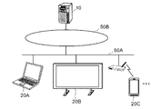
- FIGS. 1A and 1B are schematic diagrams showing a configuration of a collaborative work system according to the present embodiment.
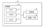
- FIGS. 2A and 2B are block diagrams showing a configuration of a server.
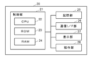
- FIGS. 3A and 3B are block diagrams showing a configuration of a client terminal.
- It is. 4A, 4B, and 4C are schematic diagrams illustrating an example of the setting / updating control of the relay server according to the present embodiment
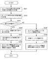
- FIGS. 5, 7, and 8 are flowcharts illustrating the operation of the server according to the present embodiment.
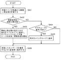
- FIG. 6 is a flowchart showing the operation of the client terminal of this embodiment.
- the collaborative work system includes a server 10 that manages collaborative work such as a remote conference and a plurality of client terminals 20 that are used by users who perform collaborative work.
- One of the client terminals 20 operates as a relay server.
- the collaborative work system includes a server 10 and a plurality of client terminals 20 such as a computer terminal 20A, a large display device 20B, and a portable terminal 20C.
- the server 10 and the plurality of client terminals 20 are communication networks such as LAN (Local Area Network) and WAN (Wide Area Network) defined by standards such as Ethernet (registered trademark), token ring, and FDDI (Fiber-Distributed Data Interface). 50 is connected.
- FIG. 1A shows the collaborative work system in which the server 10 and the plurality of client terminals 20 are connected to the same communication network 50, the plurality of client terminals 20 (computer terminals 20A) are illustrated in FIG. 1B.
- the large-scale display device 20B, the portable terminal 20C, etc.) are connected to the intranet 50A of the workplace (base), and the server 10 is connected to the Internet 50B. it can.
- each device will be described in detail.
- the server 10 is a computer device that controls communication between the client terminals 20, and as shown in FIG. 2A, a control unit 11, a storage unit 15, a communication I / F unit 16, and a display unit as necessary. It consists of an operation unit.
- the control unit 11 includes a CPU (Central Processing Unit) 12 constituted by a microprocessor and a memory such as a ROM (Read Only Memory) 13 and a RAM (Random Access Memory) 14.
- the operation of the entire server 10 is controlled by calling up a control program from the storage unit 15 and expanding and executing it in the RAM 14.
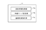
- the control unit 11 also functions as a role information acquisition unit 11a, a relay server setting unit 11b, a communication control instruction unit 11c, and the like.
- the role information acquisition unit 11a indicates to each client terminal 20 the role of each client terminal 20 in the joint work when the joint work starts or when the client terminal 20 participates in or leaves the joint work.
- Information (hereinafter referred to as role information) is instructed to be transmitted, and role information is acquired from each client terminal 20.
- the role information is an index representing the role of each client terminal 20 in joint work. For example, the screen size information of the display unit of each client terminal 20, the number of users using each client terminal 20, the user type, and the like User information, physical position at the base of each client terminal 20 or position information indicating the position on the communication network 50, capability information indicating the processing capability of each client terminal 20, and the like.
- the relay server setting unit 11b sets the client terminal 20 to be operated as a relay server from among the plurality of client terminals 20 based on the role information acquired from each client terminal 20. Specifically, the relay server setting unit 11b identifies the client terminal 20 that plays an important role in the collaborative work based on the role information acquired from each client terminal 20, and other clients are assigned to the identified client terminal 20.
- the client terminal 20 is set as a relay server so that the editing performed on the terminal 20 is reflected earliest. For example, since the client terminal 20 having the largest screen size of the display unit is used by many users and is considered to play a central role in collaborative work, the client terminal 20 may be set as a relay server.
- the client terminal 20 since the client terminal 20 used by many users and the client terminal 20 used by a person in charge of collaborative work are considered to play a central role in the collaborative work, the client terminal 20 May be set as a relay server. Further, the client terminal 20 (the client terminal 20 arranged near the center among the plurality of client terminals 20) arranged near the center of the base where the client terminal 20 is arranged plays a central role in the collaborative work. Based on the physical position of each client terminal 20 at the base, the client terminal 20 located near the center is identified from among the plurality of client terminals 20, and the client terminal 20 is set as a relay server. May be.
- the relay server setting unit 11b sets or updates the relay server for each group of client terminals 20 that are close to each other in physical position or communication network 50 (for example, within a predetermined distance range).
- the communication control instruction unit 11c instructs the client terminal 20 set as a relay server to perform communication control as a relay server.
- the client terminal 20 set as a relay server is instructed to accept a connection from another client terminal 20, and editing information for joint work data performed by the own terminal and the other client terminal 20 (Hereinafter referred to as editing information) is instructed to be transmitted to the server 10 and other client terminals 20 that have accepted the connection.
- the client terminal 20 that is not set as a relay server is instructed to control communication with the relay server.
- address information on the network 50 of the client terminal 20 that functions as the relay server for example, IP (Internet Protocol) address
- IP Internet Protocol
- the communication control instruction unit 11c The terminal 20 is notified of the address information of the relay server of the group different from the group of the client terminals 20 to which the relay server belongs (for example, the group of the client terminals 20 at other bases) or the address information of the server 10 Then, the editing information of the own terminal is instructed to be transmitted to a relay server of another group (another base) or directly to the server 10. At that time, the client terminal 20 connected to the relay server of another group or directly connected to the server 10 is selected according to the priority order based on the role information.
- the role information acquisition unit 11a, the relay server setting unit 11b, and the communication control instruction unit 11c may be configured as hardware, or are recorded on a computer-readable recording medium. It may be configured as an application (communication control program) that functions as the acquisition unit 11a, relay server setting unit 11b, and communication control instruction unit 11c, and the communication control program may be executed by the CPU 12 (hardware processor).
- the storage unit 15 includes a memory, an HDD (Hard Disk Drive), an SSD (Solid State Drive), and the like, role information received from each client terminal 20, and address information of each client terminal 20 connected to the communication network 50.
- the editing information received from the client terminal 20 functioning as a relay server is stored.
- the communication I / F unit 16 includes a NIC (Network Interface Card), a modem, and the like, establishes communication with the client terminal 20 connected to the communication network 50, and plays role information and participation / exit from each client terminal 20. A request is received, or editing information is received from the client terminal 20 set as a relay server.
- NIC Network Interface Card
- the client terminal 20 is a terminal for browsing and editing collaborative work data composed of one or a plurality of objects.
- the client terminal 20 is a computer terminal such as a personal computer, a portable terminal such as a smartphone or a tablet terminal, a large size such as a projector or a large display. Consists of display devices.
- the client terminal 20 includes a control unit 21, a storage unit 25, a communication I / F unit 26, a display unit 27, an operation unit 28, and the like.
- the control unit 21 includes a CPU 22 configured by a microprocessor and the like, and a memory such as a ROM 23 and a RAM 24.
- the CPU 22 calls a control program from the ROM 23 and the storage unit 25, expands it in the RAM 24, and executes it. The operation of the entire client terminal 20 is controlled.
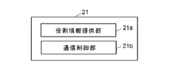
- the control unit 21 also functions as a role information providing unit 21a, a communication control unit 21b, and the like.
- the role information providing unit 21a is responsible for the role information of the own terminal (screen size information of the display unit 27, the number of users using the own terminal, the user type, etc. Information, position information indicating the physical or physical position of the terminal itself, the processing capability of the CPU 22 of the terminal itself, and the capability information indicating the data communication speed of the communication I / F unit 26) are provided to the server 10. Note that when the user is requested to log in when using the client terminal 20, user information such as the number of users and user type can be acquired from the login information.
- the client terminal 20 includes an RFID (Radio Frequency Identification) reader or the like
- user information such as the number of users and the user type is acquired from identification information obtained by reading the tag attached to the identification card with the RFID reader. be able to.
- the client terminal 20 includes a camera or the like that captures the user
- user information such as the number of users and the user type can be acquired by analyzing the image captured by the camera and extracting a person.
- the communication control unit 21b sets the transmission destination of the editing information of the collaborative work data, and transmits the editing information of the collaborative work data to the set transmission destination.
- the communication I / F unit 26 is controlled to accept connections from other client terminals 20, and to the server 10 and other The client terminal 20 is set as the editing information transmission destination.
- the communication I / F unit 26 is controlled to connect to the client terminal 20 set as the relay server using the address information received from the server 10. Then, the client terminal 20 set in the relay server is set as the transmission destination of the editing information.
- the client terminal 20 set as the relay server may transmit the editing information to another client terminal 20 other than the predetermined client terminal 20, The editing information may be transmitted to all other client terminals 20 including the predetermined client terminal 20 (that is, the editing information is also transmitted to the client terminal 20 that has transmitted the editing information).
- the role information providing unit 21a and the communication control unit 21b may be configured as hardware, or are recorded on a computer-readable recording medium, and when executed, the control unit 21 is changed to the role information providing unit 21a and the communication control unit. It may be configured as an application (communication control program) that functions as 21b, and the communication control program may be executed by the CPU 22 (hardware processor) of each client terminal 20 of the collaborative work system.
- the storage unit 25 includes a memory, an HDD, an SSD, and the like. Role information transmitted to the server 10, address information received from the server 10, editing information transmitted to other client terminals 20, and client terminals set as relay servers The editing information received from 20 is stored.
- the communication I / F unit 26 includes a NIC, a modem, and the like, establishes communication with other client terminals 20 and the server 10 connected to the communication network 50, and receives a role information transmission instruction from the server 10.
- the server 10 transmits role information and a join / leave request to the server 10, and transmits / receives editing information between the client terminal 20 set as a relay server and other client terminals 20.
- the display unit 27 is configured by an LCD (Liquid Crystal Display), an organic EL (Electro Luminescence) display, or the like, and displays joint work data and also displays joint work data based on editing information of the own terminal or another client terminal 20. Edit and display.
- LCD Liquid Crystal Display
- organic EL Electro Luminescence
- the operation unit 28 includes a mouse, a keyboard, a touch sensor including grid-like electrodes arranged on the display unit 27, and the like.
- the operation unit 28 performs an operation for editing collaborative work data (for example, movement or enlargement / reduction of an object, handwriting input, Accept operations such as text input and image pasting.
- 1A to 3B are examples of the collaborative work system of the present embodiment, and the configuration and control contents can be changed as appropriate.
- all the client terminals 20 are configured as shown in FIGS. 3A and 3B.
- the control unit 21 can operate as the role information providing unit 21a and the communication control unit 21b, The configuration need not be the same.
- the control unit 11 of the server 10 determines that the large display device 20B such as a projector or a large display is the client terminal 20 having the highest role in collaborative work, and uses the computer terminal 20A such as a personal computer as collaborative work. Assume that the client terminal 20 has the next highest role.
- client terminals 20 are arranged at a plurality of bases, and in FIGS. 4A, 4B, and 4C, the client terminals 20 are arranged at one base among the client terminals 20 participating in the joint work. It is assumed that the client terminal 20 is shown. 4A, 4B, and 4C, devices surrounded by a thick line represent devices that are set as relay servers.
- the control unit 11 (relay of the server 10)
- the server setting unit 11b) instructs the computer terminal 1 to connect directly to the server 10.
- the control unit 11 (relay server setting unit 11b) of the server 10 Based on the role information of the client terminal, the client terminal 20 having a relatively large role in the collaborative work is set as a relay server, and the other client terminals 20 are instructed to connect to the relay server.
- the control unit 11 (relay server setting unit 11b) of the server 10 sets the computer terminal 1 (see 20A1 in FIG. 4B) as a relay server, and the computer terminal 2 (see 20A2 in FIG. 4B). Is instructed to connect to the relay server.
- the control unit 11 (relay server setting unit 11b) of the server 10 collaborates based on the role information of each client terminal.
- the large display device 20B having a relatively large role in the work is switched to the relay server, and the other client terminal 20 is instructed to connect to the relay server.
- the control unit 11 (relay server setting unit 11b) of the server 10 displays a large display set as a relay server for the computer terminal 1 and the computer terminal 2 (see 20A1 and 20A2 in FIG. 4C). Instruct to connect to the device 20B.
- the relay server has a role of gathering communication of the client terminals 20 connected under the relay server.
- the relay server transmits the editing information to the other subordinate client terminals 20.
- the information is transmitted to a certain computer terminal 2 (see 20A2 in FIG. 4C) (see T02 in the figure), and is transmitted to the upper server 10 (see T03 in the figure). It is transmitted to the relay server at the base (see T04 in the figure).
- the higher level server 10 transmits the editing information to the relay server at the site (see T12 in the figure).
- the server transmits the editing information to the computer terminals 1 and 2 (20A1 and 20A2 in FIG. 4C), which are all the client terminals 20 under the control (see T13 in the figure).
- the control unit 11 of the server 10 has a physical position or a position on the communication network 50 such as a group of the client terminals 20 arranged at one base, which is close (within a predetermined distance range).
- the client terminal 20 to be operated as a relay server is set / updated according to the role of each client terminal 20, and control is performed to perform data communication between the client terminals 20 via the relay server.
- the client terminal 20 set as a relay server and having the largest role in the collaborative work reflects the editing performed in the other client terminals 20 earliest, so that the collaborative work can be efficiently advanced. it can.
- the client terminal 20 is simply described as a terminal as necessary.
- the control unit 11 (role information acquisition unit 11a) of the server 10 requests each client terminal 20 participating in the collaborative work to transmit role information, and acquires the role information from each client terminal 20 (S101).
- the control unit 11 sets a group of terminals according to the physical location of each client terminal 20 or the location on the network (S102). For example, the client terminals 20 arranged at one base are grouped together as a group of client terminals 20 that are relatively close to each other in physical position or communication network (that is, within a predetermined distance).
- the control part 11 collects the client terminals 20 existing in the same room or within a certain distance as one group.
- entry / exit management using RFID GPS (Global Positioning System), or the like can be used as a method of acquiring whether or not the room is in the same room.
- a client terminal 20 having a close IP address for example, a client terminal 20 connected to the same LAN
- a position on the communication network is within a predetermined distance range.
- the communication environment (bandwidth, delay, etc.) between the client terminals 20 is measured, and those whose communication environment is a certain level or more are grouped together as a terminal whose position on the communication network is within a predetermined distance. it can.
- control unit 11 determines whether the number of client terminals 20 belonging to the group is one or plural for each group (base) (S103). When the number of terminals 20 is one, a relay server is not provided, and the control unit 11 (communication control instruction unit 11c) transmits the address information of the server 10 to the client terminal 20 to the client terminal 20. And instruct to connect directly to the server 10 (S106).
- the control unit 11 selects one of the plurality of client terminals 20 based on the role information of each client terminal 20.
- a stand is selected and set as a client terminal 20 that operates as a relay server (S104).
- each client terminal 20 For example, based on the role information of each client terminal 20, from among the client terminals 20, the client terminal 20 having a relatively large screen size, the client terminal 20 having a relatively large number of users in use, or Client terminal 20 used by an important user in collaborative work, or a client terminal 20 arranged near the center of the base (a client terminal 20 arranged near the center among the plurality of client terminals 20), or The client terminal 20 having a relatively high processing capability is selected and set as the client terminal 20 that operates as a relay server.
- control unit 11 (communication control instruction unit 11c) instructs the selected client terminal 20 to become a relay server (instruction to accept a connection from another client terminal 20), and other clients
- the relay server address information is transmitted to the terminal 20 to instruct to connect to the relay server (S105).
- each client terminal 20 executes the processing of each step shown in the flowchart of FIG. 6 by developing the communication control program stored in the ROM 23 or the storage unit 25 in the RAM 24 and executing it.
- the control unit 21 (role information providing unit 21a) of each client terminal 20 uses the role information of the own terminal (screen size information of the display unit 27 and the own terminal).
- the user information such as the number of users and the user type, the location information of the own terminal, the capability information of the own terminal, etc.) are transmitted to the server 10 (S202).
- control unit 21 communication control unit 21b of each client terminal 20 executes a communication control process for transmitting the editing information of the joint work data to a predetermined transmission destination.
- the control unit 21 receives an instruction from the server 10 to accept connections from other client terminals 20 (S204).
- the address information of the server 10 and the other client terminal 20 that has accepted the connection is set as the transmission destination of the editing information of the joint work data (S206).
- the control unit 21 receives the address information of the client terminal 20 set as the relay server from the server 10 (S207). ), The relay server is connected (S208), and the received address information is set as the transmission destination of the editing information of the joint work data (S209). That is, the client terminal 20 that has received an instruction to accept a connection from another client terminal 20 functions as a relay server, and the client terminal 20 that has received the address information of the relay server is placed under the relay server. Each terminal functions as a terminal, and transmits the editing information of the joint work data to the set transmission destination.
- the largest screen size, the largest number of users in use, or an important user in collaborative work is specified.
- the client terminal 20 installed near the center of the base (located near the center of the plurality of client terminals 20), or have the highest processing capability, the importance in the collaborative work.
- the CPU 12 of the server 10 executes the process of each step shown in the flowcharts of FIGS. 7 and 8 by developing the communication control program stored in the ROM 13 or the storage unit 15 in the RAM 14 and executing it.
- the control unit 11 of the server 10 determines that a large display device such as a projector or a large display is the client terminal 20 having the highest role in joint work, and uses a computer terminal such as a personal computer as a role in joint work. Is determined to be the next highest client terminal 20, and it is determined that a portable terminal such as a smartphone or a tablet terminal has a low role in collaborative work and is not suitable as a relay server.
- the control unit 11 determines, for each group, whether the number of client terminals 20 belonging to the group is one or a plurality (S304). If there are a plurality of units, it is determined whether there are computer terminals or large display devices (S305). If the number of client terminals 20 belonging to the group is one in S304, or there are a plurality of client terminals 20 belonging to the group in S304, and the computer terminal is also displayed in a large size among the plurality of client terminals 20 in S305. When there is no device, the relay server is not provided, and the control unit 11 (communication control instruction unit 11c) transmits the address information of the server 10 to all the client terminals 20 and directly transmits the server 10 to all the client terminals 20. Is instructed to connect to (S306).
- control unit 11 when there are computer terminals or large display devices in the plurality of client terminals 20 in S305, the control unit 11 (relay server setting unit 11b) has large display devices in the plurality of client terminals 20. Is determined (S307).
- the control unit 11 determines whether there is a large display device already set as a relay server (S308). If there is a large display device set as a relay server, the client terminal 20 participating in the collaborative work is instructed to connect to the relay server without changing the network configuration (S309). On the other hand, when there is no large display device set as a relay server, the control unit 11 (relay server setting unit 11b) updates the relay server to a large display device (S310), and the control unit 11 (communication control instruction unit). 11c) instructs the large display device to become a relay server (instructs to accept a connection from another client terminal 20) and connects the other client terminal 20 to the relay server. An instruction (transmission server address information) is sent (S311).
- the control unit 11 determines whether there is a terminal already set as a relay server (S312). If there is a terminal set as a relay server, the client terminal 20 participating in the collaborative work is instructed to connect to the relay server without changing the network configuration (S313). On the other hand, if there is no terminal set as a relay server, the control unit 11 (relay server setting unit 11b) operates as a relay server from among a plurality of computer terminals based on the role information of each terminal.
- Select a computer terminal (largest screen size, most users in use, or used by a specific user such as an important user in collaboration, or near the center of the base (multiple
- the client terminal 20 is installed in the vicinity of the center of the client terminal 20 or the computer terminal having the highest processing capacity is selected) to update the relay server (S314), and the control unit 11 (communication control instruction unit 11c) Instruct the selected client terminal 20 to become a relay server (instruct to accept connections from other client terminals 20) Together, it instructed to connect to the relay server to the other client terminal 20 (transmission address information of the relay server) to (S315).
- the client terminal 20 is continuously used as a relay server.
- the role information of the client terminal 20 that is a server candidate may be compared, and the client terminal 20 having the highest role in collaborative work may be switched.
- the control unit 11 of the server 10 compares the role information of these client terminals 20 and has the highest role in collaborative work.
- the client terminal 20 may be selected as a relay server. Since the client terminal 20 functioning as a relay server is more burdensome than the normal client terminal 20, when there are a plurality of options, the control unit 11 of the server 10 selects the client terminal 20 having the highest performance as a relay server. Thus, the performance of the entire collaborative work system can be improved.
- the control unit 11 of the server 10 When a new client terminal 20 participates in a collaborative work or the client terminal 20 performing the collaborative work leaves and the network configuration is changed to update the relay server, the control unit 11 of the server 10 The relay server is switched only when the type of the client terminal 20 changes between the previous relay server and the changed relay server (that is, the type of the client terminal 20 that operates as the relay server does not change before and after the network configuration change). May not be updated).
- the control unit 11 of the server 10 checks the performance difference between the previous relay server and the changed relay server, and switches the relay server only when the performance difference is equal to or greater than a predetermined value. (In other words, the update is not performed when the performance difference between the client terminals 20 operating as a relay server before and after the change of the network configuration is less than a predetermined value). By performing such control, it is possible to prevent unnecessary switching of the relay server.
- the control unit 11 of the server 10 sets a relay server from among a plurality of client terminals 20 in the group and connects other client terminals 20 under the relay server.
- the control unit 11 of the server 10 exceeds the upper limit.
- the address information of the relay server of another group or the address information of the server 10 is notified to the client terminal 20 and the client terminal 20 for exceeding the upper limit relays the editing information of the joint work data to the other group. It can be transmitted to the server or directly to the server 10.
- the operation of the server 10 in that case will be described with reference to the flowchart of FIG. 8 is performed after the control unit 11 of the server 10 determines the relay server in the above-described flow (after S105 in FIG. 5 and S309, S311, S313, and S315 in the flow in FIG. 7). .
- the control unit 11 calculates the upper limit number of connectable client terminals 20 (connection upper limit number) based on the performance of the client terminal 20 set / updated as a relay server (S401). ), It is determined whether the current number of connected terminals exceeds the calculated upper limit number of connections (S402).
- the method for calculating the upper limit number of connections is not particularly limited. For example, the load on the CPU 22 when transmitting editing information to one client terminal 20 is acquired from the client terminal 20 set / updated as a relay server. The number of units with the total load of the CPU 22 having a predetermined value can be set as the upper limit number of connections.
- the control unit 11 When determining that the current number of connected terminals exceeds the upper limit number of connections, the control unit 11 (communication control instruction unit 11c) replaces the client terminals 20 corresponding to the number exceeding the upper limit number of connections with the original client terminal 20 To the other group (main group) (subgroup consisting of client terminals 20 in the same location as the client terminal 20 of the main group, but exceeding the upper limit number of connections).
- the relay server setting process after S103 in FIG. 5 or the relay server update process after S304 in FIG. 7 is performed on the client terminal 20 (S403).
- control unit 11 communication control instruction unit 11c of the server 10 notifies the address information of the relay servers of other groups to the client terminal 20 that has exceeded the upper limit number of connections, and the client that has exceeded the upper limit number of connections.
- the communication control unit 21b of the terminal 20 can transmit the editing information of the joint work data to the relay server of another group.
- control unit 11 (communication control instruction unit 11c) confirms whether the client terminal 20 exists in the subgroup (S404), and the client terminal in the subgroup. If there is 20, the client terminal 20 is added to the original group (main group) until the upper limit number of connections is reached (S405).
- control unit 11 instructs each client terminal 20 to configure the determined network (S406). Specifically, the client terminal 20 added to the subgroup is instructed to connect to the relay server set / updated in the subgroup, and the client terminal 20 added to the main group is instructed. Instruct to connect to the relay server set in the main group. Thereby, the control part 21 (communication control part 21b) of each client terminal 20 can transmit the edit information of joint work data to the transmission destination designated by the control part 11 (communication control instruction
- the control unit 11 of the server 10 forms a new group (subgroup) with the client terminals 20 that exceed the upper limit number of connections, and selects a relay server from the client terminals 20 therein.
- the control unit 11 communication control instruction unit 11c
- the control unit 11 notifies the client terminal 20 that has exceeded the upper limit number of connections of the address information of the server 10, and the communication of the client terminal 20 that has exceeded the upper limit number of connections.
- the control unit 21b may directly send the editing information of the joint work data to the server 10.
- control unit 11 of the server 10 may set a priority order for the client terminal 20 connected to the relay server of the original group (main group) according to the role in the joint work. For example, when there is a mobile terminal among the client terminals 20 connected to the relay server of the main group, the mobile terminal may be preferentially connected to the relay server of the main group, or a large display device may be used. You may make it connect with priority to the relay server of a main group, and may give priority to both.
- the client terminal 20 is exemplified by three types: a computer terminal such as a personal computer, a portable terminal such as a smartphone or a tablet terminal, and a large display device such as a projector or a large display. Any device capable of working can be used.
- a computer terminal such as a personal computer
- a portable terminal such as a smartphone or a tablet terminal
- a large display device such as a projector or a large display. Any device capable of working can be used.
- the server 10 instructs the client terminal 20 set as a relay server to accept a connection from another client terminal 20, and also sets the client set as a relay server to the other client terminal 20.
- the address information of the terminal 20 is notified, the connection to the client terminal 20 is instructed, and the client terminal 20 set as the relay server sends the client terminal 20 that has received the connection the transmission destination of the edit information of the joint work data
- the server 10 notifies the address information of the server 10 and all other client terminals 20 to the client terminal 20 set as the relay server, and sets as the relay server to all other client terminals 20.
- the client terminal 20 can also be adapted to set the address information notified from the server 10 to the destination of the editing information collaboration data.
- the present invention relates to a collaborative work system for performing collaborative work by reflecting editing of collaborative work data performed on one terminal via a relay server on another terminal, a communication control method for controlling communication via the relay server,
- the present invention can be used for a communication control program and a recording medium on which the communication control program is recorded.
Landscapes
- Engineering & Computer Science (AREA)
- Theoretical Computer Science (AREA)
- Signal Processing (AREA)
- Physics & Mathematics (AREA)
- General Engineering & Computer Science (AREA)
- General Physics & Mathematics (AREA)
- Computer Networks & Wireless Communication (AREA)
- Information Transfer Between Computers (AREA)
- Telephonic Communication Services (AREA)
Abstract
サーバと複数の端末とが接続されるシステムにおいて、適切に中継サーバを設定して、共同作業を効率的に進めることができる共同作業システム、通信制御方法及び通信制御プログラムを提供する。サーバは、各々の端末から役割情報を取得し、取得した役割情報に基づいて、複数の端末の中から共同作業データの編集情報を中継する中継サーバとして動作させる端末を設定し、中継サーバとして設定された端末に他の端末からの接続を受け付けるように指示すると共に、他の端末に中継サーバとして設定された端末のアドレス情報を通知して当該端末に接続するように指示する。各々の端末は、サーバに自端末の役割情報を提供し、中継サーバとして設定された端末は、他の端末からの接続を受け付けてサーバ及び他の端末を編集情報の送信先に設定し、他の端末は、中継サーバとして設定された端末に接続して当該端末を編集情報の送信先に設定する。
Description
本発明は、共同作業システム、通信制御方法及び通信制御プログラムに関し、特に、中継サーバを介して一の端末で行われた共同作業データの編集を他の端末に反映させて共同作業を行う共同作業システム、中継サーバを介した通信を制御する通信制御方法及び通信制御プログラムに関する。
サーバに保存された共同作業データを複数の端末にて同時に共有表示し、共同で編集できるようにすることにより、遠隔会議等でコンテンツ共有を実現する共同作業システムが提案されている。この共同作業システムにおいて、その場に存在する端末間では出来るだけ早く共同作業データの編集を反映させたいという要求がある。この要求を実現する方法としては、例えば、複数の端末が配置される拠点に中継サーバを設ける方法が考えられる。
上記の共同作業システムに関する発明ではないが、データの中継に関する技術として、例えば、下記特許文献1には、クライアントと複数のサーバとの間で受け渡される通信情報を中継する機能を有するデータ中継サーバが開示されている。このデータ中継サーバは、属性管理テーブルを記憶する記憶手段、第1の連携手段、第2の連携手段、及びデータ記憶手段を有しており、サーバ固有属性名と共有属性名との対応付けを予め属性管理テーブルによって管理しておくことで、第1のサーバ固有属性名と第2のサーバ固有属性名との対応付けを属性管理テーブルに登録された共有属性名を介して行うことが可能となり、データ中継サーバ上で出力データと入力データとの連携を実現できると記載されている。
また、複数の端末をネットワークで接続するシステムにおける通信形態を変更する技術に関して、例えば、下記特許文献2には、IP網に接続し、多地点に配置した複数のクライアント端末と、前記IP網に接続し、会議に参加する前記複数のクライアント端末の会議通信を制御する多地点会議装置と、からなる多地点会議システムが開示されている。この多地点会議システムにおいて、前記多地点会議装置は、会議に参加する前記複数のクライアント端末の台数を監視し、前記台数が所定数以下の場合、会議に参加する前記複数のクライアント端末相互間の会議通信を制御し、前記台数が所定数を超える場合には、音声データおよび映像データを会議に参加する前記クライアント端末に配信する会議通信を制御する。
中継サーバは、共同作業に参加する複数の端末が配置される拠点におけるネットワーク構成が最適となるように設定されることが好ましい。そこで、従来は、データ処理能力が高い機器(例えば、プロセッサの演算処理速度が大きい機器や、データ通信速度が大きい機器など)を拠点に配置して中継サーバとして設定し、その中継サーバに拠点内の複数の端末を順次接続してネットワークを構成していた。
このように、データ処理能力が高い機器を中継サーバに設定することにより、拠点全体のデータ処理を速くすることができるが、共同作業においては、拠点全体のデータ処理よりも特定の端末のデータ処理を速くした方が共同作業を効率的に進めることができる場合がある。例えば、拠点内の複数の端末には、1人のユーザが使用するパーソナルコンピュータなどのコンピュータ端末や、スマートフォンやタブレット端末などの携帯端末もあれば、複数のユーザが使用するプロジェクタや大型ディスプレイなどの大型表示機器もある。そして、各々の端末は共同作業における役割が異なり、多くのユーザが使用している端末や拠点の主要な場所に設置されている端末などの特定の端末は共同作業における重要度が高く、この特定の端末にできるだけ早く他の端末で行われた編集を反映させることが望ましい。従って、中継サーバを設定することによって拠点全体のデータ処理を速くすることができたとしても、必ずしも共同作業を効率的に進めることができない。
更に、携帯端末を用いるなどして参加者が遠隔地などからテンポラリーに参加するというような会議形態では、新たに会議に参加する端末(ネットワークに追加される端末)や会議から退出する端末(ネットワークから除外される端末)が随時発生し、ネットワーク構成が変化する。そのため、初期段階でネットワーク構成が最適になるように中継サーバを設定したとしても、端末の参加/退出によりネットワーク構成が変化することにより共同作業を効率的に進めることができない場合が生じる。この問題に対して、特許文献2では端末の台数に応じて動的に通信方式を変えているが、上述したように共同作業システムでは共同作業における役割が各々異なる様々な種類の端末が使用されるため、単に台数に基づいて通信方式を変えても共同作業を効率的に進めることができない。
本発明は、上記問題点に鑑みてなされたものであって、その主たる目的は、サーバと複数の端末とが接続されるネットワークにおいて、適切に中継サーバを設定して、共同作業を効率的に進めることができる共同作業システム、通信制御方法及び通信制御プログラムを提供することにある。
また、本発明の他の目的は、端末の参加/退出によりネットワーク構成が変化した場合でも、適切に中継サーバを更新して、共同作業を効率的に進めることができる共同作業システム、通信制御方法及び通信制御プログラムを提供することにある。
本発明の一側面は、共同作業データの閲覧、編集を行う複数の端末と、前記複数の端末の通信を制御するサーバと、が通信ネットワークで接続され、一の端末で行われた前記共同作業データの編集を他の端末に反映させて共同作業を行う共同作業システムであって、前記サーバは、各々の端末から、前記共同作業における各端末の役割を示す役割情報を取得する役割情報取得部と、前記各々の端末から取得した前記役割情報に基づいて、前記複数の端末の中から、前記共同作業データの編集情報を中継する中継サーバとして動作させる端末を設定する中継サーバ設定部と、前記中継サーバとして設定された端末に、他の端末からの接続を受け付けるように指示すると共に、前記他の端末に、前記中継サーバとして設定された端末のアドレス情報を通知して、前記中継サーバとして設定された端末に接続するように指示する通信制御指示部と、を備え、前記各々の端末は、前記サーバに、自端末の前記役割情報を提供する役割情報提供部と、前記共同作業データの編集情報を送信する通信制御部と、を備え、前記中継サーバとして設定された端末の前記通信制御部は、前記他の端末からの接続を受け付けると共に、前記サーバ及び前記他の端末を前記共同作業データの編集情報の送信先に設定し、前記他の端末の前記通信制御部は、当該他の端末を前記中継サーバとして設定された端末に接続すると共に、前記中継サーバとして設定された端末を前記共同作業データの編集情報の送信先に設定することを特徴とする。
本発明の一側面は、共同作業データの閲覧、編集を行う複数の端末と、前記複数の端末の通信を制御するサーバと、が通信ネットワークで接続され、一の端末で行われた前記共同作業データの編集を他の端末に反映させて共同作業を行う共同作業システムにおける通信制御方法であって、前記サーバは、各々の端末から、前記共同作業における各端末の役割を示す役割情報を取得する役割情報取得処理と、前記各々の端末から取得した前記役割情報に基づいて、前記複数の端末の中から、前記共同作業データの編集情報を中継する中継サーバとして動作させる端末を設定する中継サーバ設定処理と、前記中継サーバとして設定された端末に、他の端末からの接続を受け付けるように指示すると共に、前記他の端末に、前記中継サーバとして設定された端末のアドレス情報を通知して、前記中継サーバとして設定された端末に接続するように指示する通信制御指示処理と、を実行し、前記各々の端末は、前記サーバに、自端末の前記役割情報を提供する役割情報提供処理と、前記共同作業データの編集情報を送信する通信制御処理と、を実行し、前記通信制御処理では、前記中継サーバとして設定された端末は、前記他の端末からの接続を受け付けると共に、前記サーバ及び前記他の端末を前記共同作業データの編集情報の送信先に設定し、前記他の端末は、前記中継サーバとして設定された端末に接続すると共に、前記中継サーバとして設定された端末を前記共同作業データの編集情報の送信先に設定することを特徴とする。
本発明の一側面は、一の端末で行われた共同作業データの編集を他の端末に反映させて共同作業を行う複数の端末の通信を制御するサーバで動作する通信制御プログラムであって、前記サーバに、各々の端末から、前記共同作業における各端末の役割を示す役割情報を取得する役割情報取得処理、前記各々の端末から取得した前記役割情報に基づいて、前記複数の端末の中から、前記共同作業データの編集情報を中継する中継サーバとして動作させる端末を設定する中継サーバ設定処理、前記中継サーバとして設定された端末に、他の端末からの接続を受け付けるように指示すると共に、前記他の端末に、前記中継サーバとして設定された端末のアドレス情報を通知して、前記中継サーバとして設定された端末に接続するように指示する通信制御指示処理、を実行させることを特徴とする。
本発明の一側面は、共同作業データの閲覧、編集を行う複数の端末と、前記複数の端末の通信を制御するサーバと、が通信ネットワークで接続され、一の端末で行われた前記共同作業データの編集を他の端末に反映させて共同作業を行う共同作業システムにおける各々の端末で動作する通信制御プログラムであって、前記各々の端末に、前記サーバからの要求に従って、前記サーバに、前記共同作業における自端末の役割を示す役割情報を提供する役割情報提供処理、前記共同作業データの編集情報を送信する通信制御処理、を実行させ、前記通信制御処理では、前記サーバにより前記役割情報に基づいて前記共同作業データの編集情報を中継する中継サーバとして設定された端末は、前記サーバの指示に従って接続を受け付けた端末を前記共同作業データの編集情報の送信先に設定し、前記中継サーバとして設定されなかった端末は、前記サーバの指示に従って前記中継サーバとして設定された端末に接続すると共に、前記中継サーバとして設定された端末を前記共同作業データの編集情報の送信先に設定する、ことを特徴とする。
本発明の共同作業システム、通信制御方法及び通信制御プログラムによれば、サーバと複数の端末とが接続されるネットワークにおいて、適切に中継サーバを設定して、共同作業を効率的に進めることができる。
その理由は、共同作業システムのサーバは、各々の端末から共同作業における各端末の役割を示す役割情報を取得し、各々の端末から取得した役割情報に基づいて、複数の端末の中から、共同作業データの編集情報を中継する中継サーバとして動作させる端末を設定し、中継サーバとして設定された端末に、他の端末からの接続を受け付けるように指示すると共に、他の端末には、中継サーバとして設定された端末のアドレス情報を通知して、中継サーバに接続するように指示するからである。そして、各々の端末は、サーバに、自端末の前記役割情報を提供し、中継サーバとして設定された端末は、他の端末からの接続を受け付けると共に、サーバ及び他の端末を共同作業データの編集情報の送信先に設定することにより、自端末及び他の端末で行った共同作業データの編集情報を、接続を受け付けた端末に送信し、他の端末は、中継サーバとして設定された端末に接続すると共に、前記中継サーバとして設定された端末を前記共同作業データの編集情報の送信先に設定することにより、自端末で行った共同作業データの編集情報を、サーバから通知されたアドレス情報宛てに送信する制御を行うからである。
本発明の共同作業システム、通信制御方法及び通信制御プログラムによれば、端末の参加/退出によりネットワーク構成が変化した場合でも、適切に中継サーバを更新して、共同作業を効率的に進めることができる。
その理由は、新たな端末が共同作業に参加、若しくは、共同作業を行っている端末が退出することによりネットワーク構成が変更された場合に、役割情報に基づいて、中継サーバとして動作させる端末を更新する制御を行うからである。
背景技術で示したように、サーバに保存された共同作業データを複数の端末にて同時に共有表示し、共同で編集できるようにする共同作業システムでは、その場に存在する端末間で出来るだけ早く共同作業データの編集を反映させるために中継サーバが設けられる。この中継サーバは、共同作業を行う複数の端末が配置される拠点におけるネットワーク構成が最適となるように設定されることが好ましいことから、従来は、データ処理能力が高い機器を拠点に配置して中継サーバに設定していた。
しかしながら、共同作業においては、パーソナルコンピュータなどのコンピュータ端末や、スマートフォンやタブレット端末などの携帯端末、プロジェクタや大型ディスプレイなどの大型表示機器などの様々な端末が使用され、端末毎に共同作業における役割が異なるため、データ処理能力が高い機器を中継サーバに設定して拠点全体のデータ処理を早くしても、必ずしも共同作業を効率的に進めることができない。
更に、参加者が遠隔地などからテンポラリーに参加する会議形態では、新たに会議に参加する端末(ネットワークに追加される端末)や会議から退出する端末(ネットワークから除外される端末)が随時発生し、ネットワークを構成する端末が変化する。そのため、初期段階でネットワーク構成が最適になるように中継サーバを設定したとしても、端末の参加/退出によりネットワーク構成が最適ではなくなり、共同作業を効率的に進めることができない場合が生じる。
すなわち、共同作業では、各々の端末の役割が異なり、また、新たに共同作業に参加する端末や共同作業から退出する端末が随時発生してネットワークを構成する端末が変化するため、データ処理能力が高い機器を中継サーバに設定し、その中継サーバを固定して使用する従来の方法では、共同作業を効率的に進めることができないという問題がある。
そこで、本発明の一実施の形態では、共同作業データの閲覧、編集を行う複数の端末と、これらの端末の通信を制御するサーバと、が通信ネットワークで接続され、一の端末で行われた共同作業データの編集を他の端末に反映させることにより、複数の端末で同じデータを閲覧・編集する共同作業システムにおいて、サーバにより、各端末の共同作業における役割を考慮して中継サーバを設定する。すなわち、サーバは、各々の端末から、共同作業における各端末の役割を示す役割情報を取得し、取得した役割情報に基づいて、複数の端末の中から、共同作業データの編集情報を中継する中継サーバとして動作させる端末を設定する。そして、サーバは、中継サーバとして設定された端末に、他の端末からの接続を受け付けるように指示すると共に、他の端末に、中継サーバとして設定された端末のアドレス情報を通知して、中継サーバとして設定された端末に接続するように指示する。具体的には、サーバは、他の端末での編集を最も早く反映させることが望ましい特定の端末を中継サーバとして機能させ、他の端末をその中継サーバに接続し、中継サーバを介して通信させる。このように、特定の端末を中継サーバに設定し、中継サーバを介して端末間の通信を制御することにより、中継サーバとして設定された特定の端末に他の端末で行われた編集を迅速に反映させることができ、共同作業を効率的に進めることができる。
また、共同作業では、新しく共同作業に参加する端末が生じたり、共同作業に参加している端末が共同作業から退出したりすることがあるため、端末の参加/退出が発生した段階で、サーバにより、各端末の共同作業における役割を考慮して中継サーバを更新することが望ましい。ネットワークの構成が変化する度に中継サーバを更新することにより、現在のネットワーク構成において重要な役割を果たす特定の端末に他の端末で行われた編集を迅速に反映させることができ、共同作業を効率的に進めることができる。
上記した本発明の一実施の形態についてさらに詳細に説明すべく、本発明の一実施例に係る共同作業システム、通信制御方法及び通信制御プログラムについて、図1A乃至図8を参照して説明する。図1A、1Bは、本実施例の共同作業システムの構成を示す模式図であり、図2A、2Bは、サーバの構成を示すブロック図、図3A、3Bは、クライアント端末の構成を示すブロック図である。また、図4A、4B、4Cは、本実施例の中継サーバの設定/更新制御の一例を示す模式図であり、図5、7、8は、本実施例のサーバの動作を示すフローチャート図、図6は、本実施例のクライアント端末の動作を示すフローチャート図である。
本実施例の共同作業システムは、ネットワーク上に配置された、遠隔会議等の共同作業を管理するサーバ10と、共同作業を行うユーザが利用する複数のクライアント端末20と、で構成され、複数のクライアント端末20の内の一つが中継サーバとして動作する。図1Aに示す例では、共同作業システムが、サーバ10と、コンピュータ端末20A、大型表示装置20B、及び携帯端末20Cなどの複数のクライアント端末20とで構成されている。サーバ10と複数のクライアント端末20は、イーサネット(登録商標)、トークンリング、FDDI(Fiber-Distributed Data Interface)等の規格により定められるLAN(Local Area Network)やWAN(Wide Area Network)等の通信ネットワーク50を介して接続されている。
なお、図1Aでは、サーバ10と複数のクライアント端末20とが同一の通信ネットワーク50に接続されている共同作業システムを示したが、図1Bに示すように、複数のクライアント端末20(コンピュータ端末20A、大型表示装置20B、及び携帯端末20Cなど)が職場(拠点)のイントラネット50Aに接続され、サーバ10がインターネット50Bに接続されるなど、共同作業システムにおける通信ネットワーク50の構成は適宜設定することができる。以下、各装置について詳細に説明する。
[サーバ]
サーバ10は、クライアント端末20間の通信を制御するコンピュータ装置などであり、図2Aに示すように、制御部11と記憶部15と通信I/F部16と、必要に応じて、表示部と操作部などで構成される。
サーバ10は、クライアント端末20間の通信を制御するコンピュータ装置などであり、図2Aに示すように、制御部11と記憶部15と通信I/F部16と、必要に応じて、表示部と操作部などで構成される。
制御部11は、マイクロプロセッサ等により構成されるCPU(Central Processing Unit)12と、ROM(Read Only Memory)13やRAM(Random Access Memory)14などのメモリと、で構成され、CPU12は、ROM13や記憶部15から制御プログラムを呼び出し、RAM14に展開して実行することにより、サーバ10全体の動作を制御する。上記制御部11は、図2Bに示すように、役割情報取得部11a、中継サーバ設定部11b、通信制御指示部11cなどとしても機能する。
役割情報取得部11aは、共同作業を開始する時やクライアント端末20が共同作業に参加したり共同作業から退出したりする時に、各クライアント端末20に、共同作業における各クライアント端末20の役割を示す情報(以下、役割情報と呼ぶ。)の送信を指示し、各クライアント端末20から役割情報を取得する。なお、役割情報は、共同作業における各クライアント端末20の役割を表す指標であり、例えば、各クライアント端末20の表示部の画面サイズ情報、各クライアント端末20を使用しているユーザ数やユーザ種別などのユーザ情報、各クライアント端末20の拠点における物理的な位置若しくは通信ネットワーク50上の位置を示す位置情報、各クライアント端末20の処理能力を示す能力情報などである。
中継サーバ設定部11bは、各クライアント端末20から取得した役割情報に基づいて、複数のクライアント端末20の中から、中継サーバとして動作させるクライアント端末20を設定する。具体的には、中継サーバ設定部11bは、各クライアント端末20から取得した役割情報に基づいて、共同作業において重要な役割を果たしているクライアント端末20を特定し、特定したクライアント端末20に他のクライアント端末20で行われた編集が最も早く反映されるように、当該クライアント端末20を中継サーバに設定する。例えば、表示部の画面サイズが最も大きいクライアント端末20は、多くのユーザに使用され、共同作業の中心的役割を果たすと考えられることから、そのクライアント端末20を中継サーバに設定してもよい。また、多くのユーザが使用しているクライアント端末20や共同作業を進行する責任者などが使用しているクライアント端末20は、共同作業の中心的役割を果たすと考えられることから、そのクライアント端末20を中継サーバに設定してもよい。また、クライアント端末20が配置されている拠点の中央近傍に配置されているクライアント端末20(複数のクライアント端末20のうち中央近傍に配置されているクライアント端末20)は、共同作業の中心的役割を果たすと考えられることから、各クライアント端末20の拠点における物理的な位置に基づいて、複数のクライアント端末20のうち中央近傍に位置するクライアント端末20を特定し、そのクライアント端末20を中継サーバに設定してもよい。また、表示部の画面サイズが最も大きいクライアント端末20や使用しているユーザ数が最も多いクライアント端末20、責任者が使用しているクライアント端末20、クライアント端末20が配置されている拠点中央近傍に配置されているクライアント端末20(複数のクライアント端末20のうち中央近傍に配置されているクライアント端末20)は、処理性能の高いクライアント端末20が割り当てられる蓋然性が高いと考えられることから、そのクライアント端末20を中継サーバに設定してもよい。また、中継サーバ設定部11bは、クライアント端末20が共同作業に参加したり共同作業から退出したりすることによってネットワーク構成が変更された場合、各クライアント端末20から取得した役割情報に基づいて、中継サーバとして動作させるクライアント端末20を更新する。なお、ネットワーク構成の変更前後でクライアント端末20の種類(コンピュータ端末や携帯端末、大型表示機器)が変わらない場合や、ネットワーク構成の変更前後で中継サーバとして動作させるクライアント端末20の性能差が所定値未満の場合は、中継サーバとして動作させるクライアント端末20を更新しない。また、中継サーバ設定部11bは、物理的位置若しくは通信ネットワーク50上の位置が近い(例えば、所定の距離範囲内である)クライアント端末20のグループ毎に、中継サーバの設定又は更新を行う。
通信制御指示部11cは、中継サーバとして設定されたクライアント端末20に対しては、中継サーバとして通信制御を行うように指示する。具体的には、中継サーバとして設定されたクライアント端末20に、他のクライアント端末20からの接続を受け付けるように指示して、自端末及び他のクライアント端末20で行った共同作業データに対する編集の情報(以下、編集情報と称する。)を、サーバ10及び接続を受け付けた他のクライアント端末20に送信するように指示する。また、中継サーバとして設定されなかったクライアント端末20に対しては、中継サーバに対する通信の制御を行うように指示する。具体的には、中継サーバとして設定されなかったクライアント端末20に、中継サーバとして機能するクライアント端末20のネットワーク50上のアドレス情報(例えば、IP(Internet Protocol)アドレス)を通知して、中継サーバに接続するように指示すると共に、自端末の編集情報を、通知したアドレス情報宛てに送信するように指示する。また、通信制御指示部11cは、クライアント端末20が新たに共同作業に参加することにより、中継サーバに接続されるクライアント端末20の数が予め定めた上限を超える場合は、上限を超える分のクライアント端末20に対して、この中継サーバが属するクライアント端末20のグループとは別のグループ(例えば、他の拠点のクライアント端末20のグループ)の中継サーバのアドレス情報、若しくは、サーバ10のアドレス情報を通知して、自端末の編集情報を、別のグループ(他の拠点)の中継サーバに送信、若しくは、サーバ10に直接送信するように指示する。その際、役割情報に基づく優先順位に従って、他のグループの中継サーバに接続若しくはサーバ10に直接接続するクライアント端末20を選択する。
上記役割情報取得部11a、中継サーバ設定部11b、通信制御指示部11cは、ハードウェアとして構成してもよいし、コンピュータ読み取り可能な記録媒体に記録され、実行時に、制御部11を、役割情報取得部11a、中継サーバ設定部11b、通信制御指示部11cとして機能させるアプリケーション(通信制御プログラム)として構成し、この通信制御プログラムをCPU12(ハードウェアプロセッサ)に実行させるようにしてもよい。
記憶部15は、メモリやHDD(Hard Disk Drive)、SSD(Solid State Drive)などで構成され、各クライアント端末20から受信した役割情報、通信ネットワーク50に接続されている各クライアント端末20のアドレス情報、中継サーバとして機能するクライアント端末20から受信した編集情報などを記憶する。
通信I/F部16は、NIC(Network Interface Card)やモデムなどで構成され、通信ネットワーク50に接続されているクライアント端末20との通信を確立し、各クライアント端末20から役割情報や参加/退出要求を受信したり、中継サーバとして設定されたクライアント端末20から編集情報を受信したりする。
[クライアント端末]
クライアント端末20は、1又は複数のオブジェクトで構成される共同作業データの閲覧、編集を行う端末であり、パーソナルコンピュータなどのコンピュータ端末、スマートフォンやタブレット端末などの携帯端末、プロジェクタや大型ディスプレイなどの大型表示機器などで構成される。このクライアント端末20は、図3Aに示すように、制御部21と記憶部25と通信I/F部26と表示部27と操作部28などで構成される。
クライアント端末20は、1又は複数のオブジェクトで構成される共同作業データの閲覧、編集を行う端末であり、パーソナルコンピュータなどのコンピュータ端末、スマートフォンやタブレット端末などの携帯端末、プロジェクタや大型ディスプレイなどの大型表示機器などで構成される。このクライアント端末20は、図3Aに示すように、制御部21と記憶部25と通信I/F部26と表示部27と操作部28などで構成される。
制御部21は、マイクロプロセッサ等により構成されるCPU22と、ROM23やRAM24などのメモリと、で構成され、CPU22は、ROM23や記憶部25から制御プログラムを呼び出し、RAM24に展開して実行することにより、クライアント端末20全体の動作を制御する。上記制御部21は、図3Bに示すように、役割情報提供部21a、通信制御部21bなどとしても機能する。
役割情報提供部21aは、サーバ10からの要求(役割情報の送信指示)に従って、自端末の役割情報(表示部27の画面サイズ情報、自端末を使用しているユーザ数やユーザ種別などのユーザ情報、自端末の物理的又は通信ネットワーク50上の位置を示す位置情報、自端末のCPU22の処理能力や通信I/F部26のデータ通信速度などを示す能力情報)をサーバ10に提供する。なお、クライアント端末20の使用に際してユーザにログインを要求する場合は、ログイン情報からユーザ数やユーザ種別などのユーザ情報を取得することができる。また、クライアント端末20にRFID(Radio Frequency Identification)リーダなどを備える場合は、身分証明書に添付されたタグをRFIDリーダで読み取って得た識別情報からユーザ数やユーザ種別などのユーザ情報を取得することができる。また、クライアント端末20にユーザを撮像するカメラなどを備える場合は、カメラで撮像した画像を解析して人物を抽出することによりユーザ数やユーザ種別などのユーザ情報を取得することができる。
通信制御部21bは、共同作業データの編集情報の送信先を設定し、設定した送信先に共同作業データの編集情報を送信する。具体的には、クライアント端末20が中継サーバに設定されている場合は、通信I/F部26を制御して、他のクライアント端末20からの接続を受け付け、サーバ10及び接続を受け付けた他のクライアント端末20を編集情報の送信先に設定する。また、クライアント端末20が中継サーバに設定されていない場合は、通信I/F部26を制御して、サーバ10から受信したアドレス情報を用いて中継サーバに設定されたクライアント端末20に接続すると共に、中継サーバに設定されたクライアント端末20を編集情報の送信先に設定する。なお、中継サーバとして設定されたクライアント端末20は、所定のクライアント端末20から編集情報を受信した場合、当該所定のクライアント端末20以外の他のクライアント端末20に編集情報を送信してもよいし、当該所定のクライアント端末20を含む全ての他のクライアント端末20に編集情報を送信(すなわち、編集情報の送信元のクライアント端末20にも編集情報を送信)してもよい。
上記役割情報提供部21a、通信制御部21bは、ハードウェアとして構成してもよいし、コンピュータ読み取り可能な記録媒体に記録され、実行時に、制御部21を、役割情報提供部21a、通信制御部21bとして機能させるアプリケーション(通信制御プログラム)として構成し、当該通信制御プログラムを共同作業システムの各々のクライアント端末20のCPU22(ハードウェアプロセッサ)に実行させるようにしてもよい。
記憶部25は、メモリやHDD、SSDなどで構成され、サーバ10に送信する役割情報、サーバ10から受信したアドレス情報、他のクライアント端末20に送信する編集情報、中継サーバとして設定されたクライアント端末20から受信した編集情報などを記憶する。
通信I/F部26は、NICやモデムなどで構成され、通信ネットワーク50に接続されている他のクライアント端末20やサーバ10との通信を確立し、サーバ10から役割情報の送信指示を受信したり、サーバ10に役割情報や参加/退出要求を送信したり、中継サーバとして設定されたクライアント端末20と他のクライアント端末20との間で編集情報を送受信したりする。
表示部27は、LCD(Liquid Crystal Display)や有機EL(Electro Luminescence)ディスプレイなどで構成され、共同作業データを表示すると共に、自端末又は他のクライアント端末20の編集情報に基づいて共同作業データを編集して表示する。
操作部28は、マウスやキーボード、表示部27上に配置された格子状の電極からなるタッチセンサなどで構成され、共同作業データの編集操作(例えば、オブジェクトの移動や拡大/縮小、手書き入力、テキスト入力、画像の貼り付けなどの操作)を受け付ける。
なお、図1A乃至図3Bは、本実施例の共同作業システムの一例であり、その構成や制御内容は適宜変更可能である。例えば、本実施例では、全てのクライアント端末20を図3A、3Bに示す構成としたが、制御部21が役割情報提供部21a及び通信制御部21bとして動作可能であれば、各クライアント端末20の構成は同じである必要はない。
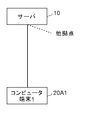
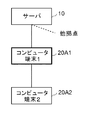
以下、上記構成の共同作業システムの動作について図4A、4B、4Cを参照して概説する。なお、以下の説明において、サーバ10の制御部11は、プロジェクタや大型ディスプレイなどの大型表示機器20Bを共同作業における役割が最も高いクライアント端末20と判断し、パーソナルコンピュータなどのコンピュータ端末20Aを共同作業における役割が次に高いクライアント端末20と判断するものとする。また、この共同作業システムでは、複数の拠点にクライアント端末20が配置されており、図4A、4B、4Cには、共同作業に参加しているクライアント端末20のうち、1拠点に配置されているクライアント端末20を示すものとする。図4A、4B、4Cにおいて、太線で囲まれた機器は中継サーバとして設定されている機器を表わす。
図4Aに示すように、最初にコンピュータ端末1(図4Aの20A1を参照)が共同作業に参加した時は、拠点内のクライアント端末20が1台であるので、サーバ10の制御部11(中継サーバ設定部11b)は、コンピュータ端末1に対して、サーバ10に直接接続するよう指示する。
次に、図4Bに示すように、2台目のコンピュータ端末2(図4Bの20A2を参照)が共同作業に参加した時は、サーバ10の制御部11(中継サーバ設定部11b)は、各々のクライアント端末の役割情報に基づいて、共同作業における役割が相対的に大きいクライアント端末20を中継サーバとして設定し、他のクライアント端末20に対して、その中継サーバに接続するよう指示する。図4Bの例では、サーバ10の制御部11(中継サーバ設定部11b)は、コンピュータ端末1(図4Bの20A1を参照)を中継サーバとして設定し、コンピュータ端末2(図4Bの20A2を参照)に対して、その中継サーバに接続するよう指示する。
次に、図4Cに示すように、大型表示機器20Bが共同作業に参加した時は、サーバ10の制御部11(中継サーバ設定部11b)は、各々のクライアント端末の役割情報に基づいて、共同作業における役割が相対的に大きい大型表示機器20Bを中継サーバに切り替え、他のクライアント端末20に対して、その中継サーバに接続するよう指示する。図4Cの例では、サーバ10の制御部11(中継サーバ設定部11b)は、コンピュータ端末1及びコンピュータ端末2(図4Cの20A1、20A2を参照)に対して、中継サーバとして設定された大型表示機器20Bに接続するよう指示する。
図4Cの状態の共同作業システムにおける中継サーバの役割を説明する。中継サーバは配下に接続されているクライアント端末20の通信をまとめる役割を持つ。例えば、配下の端末であるコンピュータ端末1(図4Cの20A1を参照)から編集情報を受信した場合には(図のT01参照)、中継サーバは、その編集情報を他の配下のクライアント端末20であるコンピュータ端末2(図4Cの20A2を参照)に送信すると共に(図のT02参照)、上位のサーバ10に送信し(図のT03参照)、上位のサーバ10は、受信した編集情報を他の拠点の中継サーバなどに送信する(図のT04参照)。
また、上位のサーバ10は、他の拠点の中継サーバなどから編集情報を受信した場合は(図のT11参照)、その編集情報を当該拠点の中継サーバに送信し(図のT12参照)、中継サーバは、その編集情報を配下の全てのクライアント端末20であるコンピュータ端末1、コンピュータ端末2(図4Cの20A1、20A2)に送信する(図のT13参照)。
このように、サーバ10の制御部11は、1拠点に配置されたクライアント端末20のグループなどの、物理的位置若しくは通信ネットワーク50上の位置が近い(所定の距離範囲内である)クライアント端末20のグループ毎に、各々のクライアント端末20の役割に応じて、中継サーバとして動作させるクライアント端末20を設定/更新し、中継サーバを介してクライアント端末20間のデータ通信を行うよう制御する。これにより、中継サーバとして設定された、共同作業における役割が最も大きいクライアント端末20には、他のクライアント端末20で行われた編集が最も早く反映されるため、共同作業を効率的に進めることができる。
以下、上記構成の共同作業システムの動作について図5乃至図8を参照して具体的に説明する。なお、図では、必要に応じてクライアント端末20を単に端末と記載している。
[サーバの動作(中継サーバの設定動作)]
まず、拠点内の複数のクライアント端末20の中から所定のクライアント端末20を選択して中継サーバに設定する時のサーバ10の動作について、図5を参照して説明する。サーバ10のCPU12は、ROM13又は記憶部15に記憶した通信制御プログラムをRAM14に展開して実行することにより、図5のフローチャート図に示す各ステップの処理を実行する。
まず、拠点内の複数のクライアント端末20の中から所定のクライアント端末20を選択して中継サーバに設定する時のサーバ10の動作について、図5を参照して説明する。サーバ10のCPU12は、ROM13又は記憶部15に記憶した通信制御プログラムをRAM14に展開して実行することにより、図5のフローチャート図に示す各ステップの処理を実行する。
サーバ10の制御部11(役割情報取得部11a)は、共同作業に参加している各クライアント端末20に役割情報の送信を要求し、各クライアント端末20から役割情報を取得する(S101)。
次に、制御部11(中継サーバ設定部11b)は、各クライアント端末20の物理的な位置やネットワーク上の位置に応じて端末のグループを設定する(S102)。例えば、1拠点に配置されたクライアント端末20などの、物理的位置若しくは通信ネットワーク上の位置が相対的に近い(すなわち、所定の距離の範囲内である)クライアント端末20を1グループとしてまとめる。各クライアント端末20の物理的な位置に応じてグループを設定する場合は、制御部11(中継サーバ設定部11b)は、同じ室内や一定距離以内などに存在するクライアント端末20を1グループとしてまとめる。なお、同じ室内かどうかや距離を取得する方法としは、例えばRFIDによる入退出管理やGPS(Global Positioning System)等を用いることができる。また、ネットワーク上の位置に応じてグループを設定する場合は、IPアドレスが近いクライアント端末20(例えば、同一LANに接続されているクライアント端末20)を、通信ネットワーク上の位置が所定の距離の範囲内である端末として1グループにまとめる。又は、クライアント端末20間の通信環境(帯域、遅延など)を測定し、通信環境が一定以上のものを、通信ネットワーク上の位置が所定の距離の範囲内である端末として1グループにまとめることもできる。
次に、制御部11(中継サーバ設定部11b)は、グループ(拠点)毎に、そのグループに属するクライアント端末20の台数が1台であるか複数台であるかを判断し(S103)、クライアント端末20の台数が1台の場合は、中継サーバを設けず、制御部11(通信制御指示部11c)は、そのクライアント端末20にサーバ10のアドレス情報を送信して、そのクライアント端末20に対して、直接サーバ10に接続するように指示する(S106)。
一方、グループに属するクライアント端末20の台数が複数台の場合は、制御部11(中継サーバ設定部11b)は、各クライアント端末20の役割情報に基づいて、複数台のクライアント端末20の中から一台を選択し、中継サーバとして動作させるクライアント端末20として設定する(S104)。例えば、各クライアント端末20の役割情報に基づいて、クライアント端末20の中から、画面サイズが相対的に大きいクライアント端末20、又は、使用しているユーザ数が相対的に多いクライアント端末20、又は、共同作業における重要なユーザが使用しているクライアント端末20、又は、拠点の中央近傍に配置されているクライアント端末20(複数のクライアント端末20のうち中央近傍に配置されているクライアント端末20)、又は、処理能力が相対的に高いクライアント端末20を選択し、中継サーバとして動作させるクライアント端末20として設定する。そして、制御部11(通信制御指示部11c)は、選択したクライアント端末20に対して中継サーバになるように指示(他のクライアント端末20からの接続を受け付けるように指示)すると共に、他のクライアント端末20に対して中継サーバのアドレス情報を送信して、中継サーバに接続するように指示する(S105)。
[クライアント端末の動作]
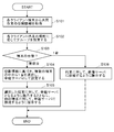
次に、クライアント端末20の動作について、図6を参照して説明する。各クライアント端末20のCPU22は、ROM23又は記憶部25に記憶した通信制御プログラムをRAM24に展開して実行することにより、図6のフローチャート図に示す各ステップの処理を実行する。
次に、クライアント端末20の動作について、図6を参照して説明する。各クライアント端末20のCPU22は、ROM23又は記憶部25に記憶した通信制御プログラムをRAM24に展開して実行することにより、図6のフローチャート図に示す各ステップの処理を実行する。
各クライアント端末20の制御部21(役割情報提供部21a)は、サーバ10から役割情報の要求を受信すると(S201)、自端末の役割情報(表示部27の画面サイズ情報や自端末を使用しているユーザ数やユーザ種別などのユーザ情報、自端末の位置情報、自端末の能力情報など)をサーバ10に送信する(S202)。
その後、各クライアント端末20の制御部21(通信制御部21b)は、共同作業データの編集情報を所定の送信先に送信する通信制御処理を実行する。中継サーバに設定されたクライアント端末20では(S203のYes)、制御部21(通信制御部21b)は、サーバ10から、他のクライアント端末20からの接続を受け付ける旨の指示を受信し(S204)、他のクライアント端末20からの接続を受け付けると(S205)、サーバ10及び接続を受け付けた他のクライアント端末20のアドレス情報を共同作業データの編集情報の送信先に設定する(S206)。また、中継サーバに設定されなかったクライアント端末20では(S203のNo)、制御部21(通信制御部21b)は、サーバ10から中継サーバに設定されたクライアント端末20のアドレス情報を受信すると(S207)、中継サーバに接続すると共に(S208)、受信したアドレス情報を共同作業データの編集情報の送信先に設定する(S209)。すなわち、他のクライアント端末20からの接続を受け付ける旨の指示を受信したクライアント端末20は、中継サーバとして機能し、中継サーバのアドレス情報を受信したクライアント端末20は、中継サーバの配下に配置される端末として機能し、それぞれ、設定された送信先に共同作業データの編集情報を送信することになる。
このように、グループ(拠点)毎に、各クライアント端末20の役割情報に基づいて、画面サイズが最も大きい、又は、使用しているユーザ数が最も多い、又は、共同作業における重要なユーザなど特定のユーザが使用している、又は、拠点の中央近傍に設置されている(複数のクライアント端末20のうち中央近傍に配置されている)、又は処理能力が最も高いなど、共同作業における重要度が高いと考えられるクライアント端末20を中継サーバとして設定し、中継サーバを介して編集情報の送受信が行われるようにネットワークを構成することにより、共同作業における重要度が高いクライアント端末20に編集を迅速に反映させることができ、共同作業を効率的に行うことができるようになる。
次に、共同作業中に、新たなクライアント端末20が共同作業に参加する、若しくは、共同作業に参加しているクライアント端末20が共同作業から退出する場合のサーバ10の動作について、図7及び図8を参照して説明する。サーバ10のCPU12は、ROM13又は記憶部15に記憶した通信制御プログラムをRAM14に展開して実行することにより、図7及び図8のフローチャート図に示す各ステップの処理を実行する。なお、以下の説明において、サーバ10の制御部11は、プロジェクタや大型ディスプレイなどの大型表示機器を共同作業における役割が最も高いクライアント端末20と判断し、パーソナルコンピュータなどのコンピュータ端末を共同作業における役割が次に高いクライアント端末20と判断し、スマートフォンやタブレット端末などの携帯端末を共同作業における役割が低く、中継サーバとして適していないと判断するものとする。
[サーバの動作(中継サーバの更新動作)]
サーバ10の制御部11(役割情報取得部11a)は、新たに共同作業に参加、若しくは、共同作業から退出するクライアント端末20から参加/退出の要求を受け付けたら(S301)、各クライアント端末20に役割情報の送信を要求し、各クライアント端末20から役割情報を取得する(S302)。次に、制御部11(中継サーバ設定部11b)は、各クライアント端末20の物理的な位置やネットワーク上の位置に応じてクライアント端末20のグループを設定する(S303)。グループの設定方法は中継サーバの設定動作時と同様である。
サーバ10の制御部11(役割情報取得部11a)は、新たに共同作業に参加、若しくは、共同作業から退出するクライアント端末20から参加/退出の要求を受け付けたら(S301)、各クライアント端末20に役割情報の送信を要求し、各クライアント端末20から役割情報を取得する(S302)。次に、制御部11(中継サーバ設定部11b)は、各クライアント端末20の物理的な位置やネットワーク上の位置に応じてクライアント端末20のグループを設定する(S303)。グループの設定方法は中継サーバの設定動作時と同様である。
次に、制御部11(中継サーバ設定部11b)は、グループ毎に、そのグループに属するクライアント端末20の台数が1台であるか複数台であるかを判断し(S304)、クライアント端末20の台数が複数台の場合は、その中にコンピュータ端末又は大型表示機器があるかを判断する(S305)。S304でグループに属するクライアント端末20の台数が1台の場合、若しくは、S304でグループに属するクライアント端末20の台数が複数台であり、S305で複数台のクライアント端末20の中にコンピュータ端末も大型表示機器も無い場合は、中継サーバを設けず、制御部11(通信制御指示部11c)は、全クライアント端末20にサーバ10のアドレス情報を送信して、全クライアント端末20に対して、直接サーバ10に接続するように指示する(S306)。
一方、S305で複数台のクライアント端末20の中にコンピュータ端末又は大型表示機器がある場合は、制御部11(中継サーバ設定部11b)は、複数台のクライアント端末20の中に大型表示機器があるかを判断する(S307)。
複数台のクライアント端末20の中に大型表示機器がある場合は、制御部11(中継サーバ設定部11b)は、既に中継サーバとして設定されている大型表示機器があるかを判断し(S308)、中継サーバとして設定されている大型表示機器がある場合は、ネットワーク構成を変えずに、共同作業に参加しているクライアント端末20に対して、中継サーバに接続するように指示する(S309)。一方、中継サーバとして設定されている大型表示機器がない場合は、制御部11(中継サーバ設定部11b)は、中継サーバを大型表示機器に更新し(S310)、制御部11(通信制御指示部11c)は、大型表示機器に対して中継サーバになるように指示(他のクライアント端末20からの接続を受け付けるように指示)すると共に、他のクライアント端末20に対して中継サーバに接続するように指示(中継サーバのアドレス情報を送信)する(S311)。
また、S307で複数台のクライアント端末20の中に大型表示機器がない場合は、制御部11(中継サーバ設定部11b)は、既に中継サーバとして設定されている端末があるかを判断し(S312)、中継サーバとして設定されている端末がある場合は、ネットワーク構成を変えずに、共同作業に参加しているクライアント端末20に対して、中継サーバに接続するように指示する(S313)。一方、中継サーバとして設定されている端末がない場合は、制御部11(中継サーバ設定部11b)は、各々の端末の役割情報に基づいて、複数台のコンピュータ端末の中から中継サーバとして動作させるコンピュータ端末を選択(画面サイズが最も大きい、又は、使用しているユーザ数が最も多い、又は、共同作業における重要なユーザなどの特定のユーザが使用している、又は、拠点の中央近傍(複数のクライアント端末20のうち中央近傍)に設置されている、又は、処理能力が最も高いコンピュータ端末を選択)して中継サーバを更新し(S314)、制御部11(通信制御指示部11c)は、選択したクライアント端末20に対して中継サーバになるように指示(他のクライアント端末20からの接続を受け付けるように指示)すると共に、他のクライアント端末20に中継サーバに接続するように指示(中継サーバのアドレス情報を送信)する(S315)。
なお、上記フローではすでに中継サーバとして設定されているクライアント端末20がある場合には、そのクライアント端末20を中継サーバとして継続して使用するようにしているが、サーバ10の制御部11により、中継サーバの候補となるクライアント端末20の役割情報を比較し、共同作業における役割が最も高いクライアント端末20に切り替えるようにしても良い。また、新たに中継サーバを設定する際に候補となるクライアント端末20が複数ある場合は、サーバ10の制御部11により、それらのクライアント端末20の役割情報を比較し、共同作業における役割が最も高いクライアント端末20を中継サーバとして選択するようにしても良い。中継サーバとして機能するクライアント端末20は、通常のクライアント端末20より負荷がかかるため、選択肢が複数ある場合には、サーバ10の制御部11により中継サーバとして最も性能の高いクライアント端末20を選択することにより、共同作業システム全体のパフォーマンスを向上させることができる。
さらに、新たなクライアント端末20が共同作業に参加、若しくは、共同作業を行っているクライアント端末20が退出することによりネットワーク構成が変更されて中継サーバを更新する際に、サーバ10の制御部11は、以前の中継サーバと変更後の中継サーバとでクライアント端末20の種類が変わる場合にのみ中継サーバを切り替える(すなわち、ネットワーク構成の変更前後で中継サーバとして動作させるクライアント端末20の種類が変わらない場合は、更新を行わない)ようにしても良い。又は、中継サーバを更新する際に、サーバ10の制御部11は、以前の中継サーバと変更後の中継サーバとの性能差を確認し、性能差が所定値以上の場合にのみ中継サーバを切り替える(すなわち、ネットワーク構成の変更前後で中継サーバとして動作させるクライアント端末20の性能差が所定値未満の場合は、更新を行わない)ようにしても良い。このような制御を行うことにより、中継サーバの無駄な切り替えを未然に防止することができる。
また、上記フローでは、サーバ10の制御部11により、グループ内の複数のクライアント端末20の中から中継サーバを設定し、その配下に他のクライアント端末20を接続したが、中継サーバとなるクライアント端末20の性能によっては、配下のクライアント端末20が増加していくと中継サーバの負荷が増え、共同作業システム全体のパフォーマンスが低下してしまう恐れがある。そのような不都合を防止するために、中継サーバとなるクライアント端末20の性能に応じて接続台数の上限を設定してもよい。これにより、新たなクライアント端末20が共同作業に参加することにより、中継サーバに接続されるクライアント端末20の数が接続台数の上限を超える場合に、サーバ10の制御部11は、上限を超える分のクライアント端末20に対して他のグループの中継サーバのアドレス情報、若しくは、サーバ10のアドレス情報を通知し、上限を超える分のクライアント端末20は、共同作業データの編集情報を他のグループの中継サーバに送信、若しくは、サーバ10に直接送信することができる。
その場合のサーバ10の動作について、図8のフローチャート図を参照して説明する。なお、図8のフローは、前述したフローにおいて、サーバ10の制御部11が中継サーバを決定した後(図5のS105、図7のフローのS309、S311、S313、S315の後)に実施する。
まず、制御部11(通信制御指示部11c)は、中継サーバとして設定/更新されたクライアント端末20の性能に基づいて、接続可能なクライアント端末20の上限台数(接続上限台数)を計算し(S401)、現在の接続端末数が計算した接続上限台数を超えているかを判断する(S402)。なお、接続上限台数の計算方法は特に限定されないが、例えば、中継サーバとして設定/更新されたクライアント端末20から、1台のクライアント端末20に編集情報を送信する際のCPU22の負荷を取得し、CPU22の総負荷が予め定めた値となる台数を接続上限台数とすることができる。
現在の接続端末数が接続上限台数を超えていると判断した場合は、制御部11(通信制御指示部11c)は、接続上限台数を超えた台数分のクライアント端末20を、元のクライアント端末20のグループ(メイングループ)とは別のグループ(メイングループのクライアント端末20と場所は同一であるが、接続上限台数を超えた分のクライアント端末20で構成されるサブグループ)に追加し、サブグループのクライアント端末20に対して、図5のS103以降の中継サーバの設定処理、若しくは、図7のS304以降の中継サーバの更新処理を行う(S403)。すなわち、サーバ10の制御部11(通信制御指示部11c)は、接続上限台数を超えたクライアント端末20に対して、他のグループの中継サーバのアドレス情報を通知し、接続上限台数を超えたクライアント端末20の通信制御部21bが、共同作業データの編集情報を他のグループの中継サーバに送信できるようにする。
一方、現在の接続端末数が接続上限台数を超えない場合は、制御部11(通信制御指示部11c)は、サブグループにクライアント端末20があるかを確認し(S404)、サブグループにクライアント端末20がある場合は、そのクライアント端末20を接続上限台数に達するまで元のグループ(メイングループ)に追加する(S405)。
その後、制御部11(通信制御指示部11c)は、決定したネットワークを構成するように各クライアント端末20に指示する(S406)。具体的には、サブグループに追加されたクライアント端末20に対しては、サブグループに設定/更新された中継サーバに接続するように指示し、メイングループに追加されたクライアント端末20に対しては、メイングループに設定された中継サーバに接続するように指示する。これにより、各クライアント端末20の制御部21(通信制御部21b)は、制御部11(通信制御指示部11c)により指定された送信先に共同作業データの編集情報を送信することができる。
上記フローでは、サーバ10の制御部11は、接続上限台数を超えた分のクライアント端末20で新しいグループ(サブグループ)を構成し、その中のクライアント端末20から中継サーバを選択するようにしているが、単に接続上限台数を超えたクライアント端末20をリストで管理し、それらをサーバ10に直接接続するようにしても良い。すなわち、サーバ10の制御部11(通信制御指示部11c)は、接続上限台数を超えたクライアント端末20に対して、サーバ10のアドレス情報を通知し、接続上限台数を超えたクライアント端末20の通信制御部21bは、共同作業データの編集情報をサーバ10に直接送信してもよい。
また、サーバ10の制御部11は、元のグループ(メイングループ)の中継サーバに接続するクライアント端末20には、共同作業における役割に応じて優先順位を設定しても良い。例えば、メイングループの中継サーバに接続するクライアント端末20の中に携帯端末がある場合には、携帯端末を優先してメイングループの中継サーバに接続するようにしても良いし、あるいは大型表示機器をメイングループの中継サーバに優先して接続するようにしても良いし、その両方を優先してもよい。
なお、本発明は上記実施例に限定されるものではなく、本発明の趣旨を逸脱しない限りにおいて、サーバ10やクライアント端末20の構成や制御部の制御は適宜変更可能である。
例えば、上記実施例では、クライアント端末20として、パーソナルコンピュータなどのコンピュータ端末、スマートフォンやタブレット端末などの携帯端末、プロジェクタや大型ディスプレイなどの大型表示機器の3種類を例示したが、クライアント端末20は共同作業が可能な任意の機器を用いることができる。
また、上記実施例では、サーバ10は、中継サーバとして設定したクライアント端末20に、他のクライアント端末20からの接続を受け付けるように指示すると共に、他のクライアント端末20に、中継サーバとして設定したクライアント端末20のアドレス情報を通知して、当該クライアント端末20に接続するように指示し、中継サーバとして設定されたクライアント端末20は、接続を受け付けたクライアント端末20を共同作業データの編集情報の送信先に設定したが、サーバ10は、中継サーバとして設定したクライアント端末20に、サーバ10及び他の全てのクライアント端末20のアドレス情報を通知すると共に、他の全てのクライアント端末20に、中継サーバとして設定したクライアント端末20のアドレス情報を通知し、各クライアント端末20は、サーバ10から通知されたアドレス情報を共同作業データの編集情報の送信先に設定するようにすることもできる。
本発明は、中継サーバを介して一の端末で行われた共同作業データの編集を他の端末に反映させて共同作業を行う共同作業システム、中継サーバを介した通信を制御する通信制御方法、通信制御プログラム及び当該通信制御プログラムを記録した記録媒体に利用可能である。
10 サーバ
11 制御部
11a 役割情報取得部
11b 中継サーバ設定部
11c 通信制御指示部
12 CPU
13 ROM
14 RAM
15 記憶部
16 通信I/F部
20 クライアント端末
20A、20A1、20A2 クライアント端末(コンピュータ端末)
20B クライアント端末(大型表示機器)
20C クライアント端末(携帯端末)
21 制御部
21a 役割情報提供部
21b 通信制御部
22 CPU
23 ROM
24 RAM
25 記憶部
26 通信I/F部
27 表示部
28 操作部
50、50A、50B 通信ネットワーク
11 制御部
11a 役割情報取得部
11b 中継サーバ設定部
11c 通信制御指示部
12 CPU
13 ROM
14 RAM
15 記憶部
16 通信I/F部
20 クライアント端末
20A、20A1、20A2 クライアント端末(コンピュータ端末)
20B クライアント端末(大型表示機器)
20C クライアント端末(携帯端末)
21 制御部
21a 役割情報提供部
21b 通信制御部
22 CPU
23 ROM
24 RAM
25 記憶部
26 通信I/F部
27 表示部
28 操作部
50、50A、50B 通信ネットワーク
Claims (23)
- 共同作業データの閲覧、編集を行う複数の端末と、前記複数の端末の通信を制御するサーバと、が通信ネットワークで接続され、一の端末で行われた前記共同作業データの編集を他の端末に反映させて共同作業を行う共同作業システムであって、
前記サーバは、
各々の端末から、前記共同作業における各端末の役割を示す役割情報を取得する役割情報取得部と、
前記各々の端末から取得した前記役割情報に基づいて、前記複数の端末の中から、前記共同作業データの編集情報を中継する中継サーバとして動作させる端末を設定する中継サーバ設定部と、
前記中継サーバとして設定された端末に、他の端末からの接続を受け付けるように指示すると共に、前記他の端末に、前記中継サーバとして設定された端末のアドレス情報を通知して、前記中継サーバとして設定された端末に接続するように指示する通信制御指示部と、を備え、
前記各々の端末は、
前記サーバに、自端末の前記役割情報を提供する役割情報提供部と、
前記共同作業データの編集情報を送信する通信制御部と、を備え、
前記中継サーバとして設定された端末の前記通信制御部は、前記他の端末からの接続を受け付けると共に、前記サーバ及び前記他の端末を前記共同作業データの編集情報の送信先に設定し、
前記他の端末の前記通信制御部は、当該他の端末を前記中継サーバとして設定された端末に接続すると共に、前記中継サーバとして設定された端末を前記共同作業データの編集情報の送信先に設定する、
ことを特徴とする共同作業システム。 - 前記中継サーバ設定部は、新たな端末が前記共同作業に参加、若しくは、前記共同作業を行っている端末が退出した場合に、前記役割情報に基づいて、前記中継サーバとして動作させる端末を更新する、
ことを特徴とする請求項1に記載の共同作業システム。 - 前記役割情報は、前記各々の端末に設けられた表示部の画面サイズであり、
前記中継サーバ設定部は、前記画面サイズが最も大きい端末を、前記中継サーバに設定する、
ことを特徴とする請求項1又は2に記載の共同作業システム。 - 前記役割情報は、前記各々の端末を使用しているユーザ数又はユーザ種別であり、
前記中継サーバ設定部は、前記ユーザ数が最も多い又は特定のユーザが使用している端末を前記中継サーバに設定する、
ことを特徴とする請求項1又は2に記載の共同作業システム。 - 前記役割情報は、前記各々の端末が配置されている位置であり、
前記中継サーバ設定部は、前記複数の端末のうち中央近傍に配置されている端末を、前記中継サーバに設定する、
ことを特徴とする請求項1又は2に記載の共同作業システム。 - 前記役割情報は、前記各々の端末の処理能力を含み、
前記中継サーバ設定部は、前記処理能力が最も高い端末を、前記中継サーバに設定する、
ことを特徴とする請求項1又は2に記載の共同作業システム。 - 物理的位置若しくは通信ネットワーク上の位置が所定の距離の範囲内である端末のグループが設定され、
前記中継サーバ設定部は、前記グループ毎に前記中継サーバの設定又は更新を行う、
ことを特徴とする請求項1乃至6のいずれか一に記載の共同作業システム。 - 前記通信制御指示部は、新たな端末が前記共同作業に参加することにより、前記中継サーバに接続される端末の数が予め定めた上限を超える場合は、前記上限を超える分の所定の端末に対して、他のグループの中継サーバのアドレス情報、若しくは、前記サーバのアドレス情報を通知し、
前記所定の端末の前記通信制御部は、前記共同作業データの編集情報を前記他のグループの中継サーバに送信、若しくは、前記サーバに直接送信する、
ことを特徴とする請求項7に記載の共同作業システム。 - 共同作業データの閲覧、編集を行う複数の端末と、前記複数の端末の通信を制御するサーバと、が通信ネットワークで接続され、一の端末で行われた前記共同作業データの編集を他の端末に反映させて共同作業を行う共同作業システムにおける通信制御方法であって、
前記サーバは、
各々の端末から、前記共同作業における各端末の役割を示す役割情報を取得する役割情報取得処理と、
前記各々の端末から取得した前記役割情報に基づいて、前記複数の端末の中から、前記共同作業データの編集情報を中継する中継サーバとして動作させる端末を設定する中継サーバ設定処理と、
前記中継サーバとして設定された端末に、他の端末からの接続を受け付けるように指示すると共に、前記他の端末に、前記中継サーバとして設定された端末のアドレス情報を通知して、前記中継サーバとして設定された端末に接続するように指示する通信制御指示処理と、を実行し、
前記各々の端末は、
前記サーバに、自端末の前記役割情報を提供する役割情報提供処理と、
前記共同作業データの編集情報を送信する通信制御処理と、を実行し、
前記通信制御処理では、前記中継サーバとして設定された端末は、前記他の端末からの接続を受け付けると共に、前記サーバ及び前記他の端末を前記共同作業データの編集情報の送信先に設定し、前記他の端末は、前記中継サーバとして設定された端末に接続すると共に、前記中継サーバとして設定された端末を前記共同作業データの編集情報の送信先に設定する、
ことを特徴とする通信制御方法。 - 前記中継サーバ設定処理では、新たな端末が前記共同作業に参加、若しくは、前記共同作業を行っている端末が退出した場合に、前記役割情報に基づいて、前記中継サーバとして動作させる端末を更新する、
ことを特徴とする請求項9に記載の通信制御方法。 - 前記役割情報は、前記各々の端末に設けられた表示部の画面サイズであり、
前記中継サーバ設定処理では、前記画面サイズが最も大きい端末を、前記中継サーバに設定する、
ことを特徴とする請求項9又は10に記載の通信制御方法。 - 前記役割情報は、前記各々の端末を使用しているユーザ数又はユーザ種別であり、
前記中継サーバ設定処理では、前記ユーザ数が最も多い又は特定のユーザが使用している端末を、前記中継サーバに設定する、
ことを特徴とする請求項9又は10に記載の通信制御方法。 - 前記役割情報は、前記各々の端末が配置されている位置であり、
前記中継サーバ設定処理では、前記複数の端末のうち中央近傍に配置されている端末を、前記中継サーバに設定する、
ことを特徴とする請求項9又は10に記載の通信制御方法。 - 前記役割情報は、前記各々の端末の処理能力を含み、
前記中継サーバ設定処理では、前記処理能力が最も高い端末を、前記中継サーバに設定する、
ことを特徴とする請求項9又は10に記載の通信制御方法。 - 物理的位置若しくは通信ネットワーク上の位置が所定の距離の範囲内である端末のグループが設定され、
前記中継サーバ設定処理では、前記グループ毎に前記中継サーバの設定又は更新を行う、
ことを特徴とする請求項9乃至14のいずれか一に記載の通信制御方法。 - 前記通信制御指示処理では、新たな端末が前記共同作業に参加することにより、前記中継サーバに接続される端末の数が予め定めた上限を超える場合は、前記上限を超える分の所定の端末に対して、他のグループの中継サーバのアドレス情報、若しくは、前記サーバのアドレス情報を通知し、
前記通信制御処理では、前記所定の端末は、前記共同作業データの編集情報を前記他のグループの中継サーバに送信、若しくは、前記サーバに直接送信する、
ことを特徴とする請求項15に記載の通信制御方法。 - 一の端末で行われた共同作業データの編集を他の端末に反映させて共同作業を行う複数の端末の通信を制御するサーバで動作する通信制御プログラムであって、
前記サーバに、
各々の端末から、前記共同作業における各端末の役割を示す役割情報を取得する役割情報取得処理、
前記各々の端末から取得した前記役割情報に基づいて、前記複数の端末の中から、前記共同作業データの編集情報を中継する中継サーバとして動作させる端末を設定する中継サーバ設定処理、
前記中継サーバとして設定された端末に、他の端末からの接続を受け付けるように指示すると共に、前記他の端末に、前記中継サーバとして設定された端末のアドレス情報を通知して、前記中継サーバとして設定された端末に接続するように指示する通信制御指示処理、を実行させる、
ことを特徴とする通信制御プログラム。 - 前記中継サーバ設定処理では、新たな端末が前記共同作業に参加、若しくは、前記共同作業を行っている端末が退出した場合に、前記役割情報に基づいて、前記中継サーバとして動作させる端末を更新する、
ことを特徴とする請求項17に記載の通信制御プログラム。 - 前記役割情報は、前記各々の端末に設けられた表示部の画面サイズであり、
前記中継サーバ設定処理では、前記画面サイズが最も大きい端末を、前記中継サーバに設定する、
ことを特徴とする請求項17又は18に記載の通信制御プログラム。 - 前記役割情報は、前記各々の端末を使用しているユーザ数又はユーザ種別であり、
前記中継サーバ設定処理では、前記ユーザ数が最も多い又は特定のユーザが使用している端末を、前記中継サーバに設定する、
ことを特徴とする請求項17又は18に記載の通信制御プログラム。 - 前記役割情報は、前記各々の端末が配置されている位置であり、
前記中継サーバ設定処理では、前記複数の端末のうち中央近傍に配置されている端末を、前記中継サーバに設定する、
ことを特徴とする請求項17又は18に記載の通信制御プログラム。 - 前記役割情報は、前記各々の端末の処理能力を含み、
前記中継サーバ設定処理では、前記処理能力が最も高い端末を、前記中継サーバに設定する、
ことを特徴とする請求項17又は18に記載の通信制御プログラム。 - 共同作業データの閲覧、編集を行う複数の端末と、前記複数の端末の通信を制御するサーバと、が通信ネットワークで接続され、一の端末で行われた前記共同作業データの編集を他の端末に反映させて共同作業を行う共同作業システムにおける各々の端末で動作する通信制御プログラムであって、
前記各々の端末に、
前記サーバからの要求に従って、前記サーバに、前記共同作業における自端末の役割を示す役割情報を提供する役割情報提供処理、
前記共同作業データの編集情報を送信する通信制御処理、を実行させ、
前記通信制御処理では、前記サーバにより前記役割情報に基づいて前記共同作業データの編集情報を中継する中継サーバとして設定された端末は、前記サーバの指示に従って接続を受け付けた端末を前記共同作業データの編集情報の送信先に設定し、前記中継サーバとして設定されなかった端末は、前記サーバの指示に従って前記中継サーバとして設定された端末に接続すると共に、前記中継サーバとして設定された端末を前記共同作業データの編集情報の送信先に設定する、
ことを特徴とする通信制御プログラム。
Priority Applications (1)
| Application Number | Priority Date | Filing Date | Title |
|---|---|---|---|
| JP2018516929A JPWO2017195587A1 (ja) | 2016-05-11 | 2017-04-25 | 共同作業システム、通信制御方法及び通信制御プログラム |
Applications Claiming Priority (2)
| Application Number | Priority Date | Filing Date | Title |
|---|---|---|---|
| JP2016095124 | 2016-05-11 | ||
| JP2016-095124 | 2016-05-11 |
Publications (1)
| Publication Number | Publication Date |
|---|---|
| WO2017195587A1 true WO2017195587A1 (ja) | 2017-11-16 |
Family
ID=60266450
Family Applications (1)
| Application Number | Title | Priority Date | Filing Date |
|---|---|---|---|
| PCT/JP2017/016305 Ceased WO2017195587A1 (ja) | 2016-05-11 | 2017-04-25 | 共同作業システム、通信制御方法及び通信制御プログラム |
Country Status (2)
| Country | Link |
|---|---|
| JP (1) | JPWO2017195587A1 (ja) |
| WO (1) | WO2017195587A1 (ja) |
Citations (5)
| Publication number | Priority date | Publication date | Assignee | Title |
|---|---|---|---|---|
| JP2010124232A (ja) * | 2008-11-19 | 2010-06-03 | Hitachi Ltd | 会議システム及び会議方法 |
| JP2014072703A (ja) * | 2012-09-28 | 2014-04-21 | Ricoh Co Ltd | 伝送管理システム、伝送システム、伝送管理方法、及びプログラム |
| JP2015173435A (ja) * | 2014-02-19 | 2015-10-01 | 株式会社リコー | 伝送システム、方法、プログラム及びシステム |
| JP2016032128A (ja) * | 2014-07-25 | 2016-03-07 | 株式会社リコー | 遠隔会議システム、通信端末及びプログラム |
| JP2016063386A (ja) * | 2014-09-18 | 2016-04-25 | 株式会社リコー | 通信装置、並びにアンテナの位置及び向きの設定方法 |
-
2017
- 2017-04-25 JP JP2018516929A patent/JPWO2017195587A1/ja active Pending
- 2017-04-25 WO PCT/JP2017/016305 patent/WO2017195587A1/ja not_active Ceased
Patent Citations (5)
| Publication number | Priority date | Publication date | Assignee | Title |
|---|---|---|---|---|
| JP2010124232A (ja) * | 2008-11-19 | 2010-06-03 | Hitachi Ltd | 会議システム及び会議方法 |
| JP2014072703A (ja) * | 2012-09-28 | 2014-04-21 | Ricoh Co Ltd | 伝送管理システム、伝送システム、伝送管理方法、及びプログラム |
| JP2015173435A (ja) * | 2014-02-19 | 2015-10-01 | 株式会社リコー | 伝送システム、方法、プログラム及びシステム |
| JP2016032128A (ja) * | 2014-07-25 | 2016-03-07 | 株式会社リコー | 遠隔会議システム、通信端末及びプログラム |
| JP2016063386A (ja) * | 2014-09-18 | 2016-04-25 | 株式会社リコー | 通信装置、並びにアンテナの位置及び向きの設定方法 |
Also Published As
| Publication number | Publication date |
|---|---|
| JPWO2017195587A1 (ja) | 2019-03-14 |
Similar Documents
| Publication | Publication Date | Title |
|---|---|---|
| US10237496B2 (en) | Graphical transitions of displayed content based on a change of state in a teleconference session | |
| US20180359293A1 (en) | Conducting private communications during a conference session | |
| US12185025B2 (en) | Video conferencing systems with meeting migration | |
| US10832223B2 (en) | Automatic remote communications session creation | |
| JP6451227B2 (ja) | 情報処理装置、情報処理システム、プログラム、及び記録媒体 | |
| EP3131257B1 (en) | Program, information processing apparatus, and information processing system for use in an electronic conference system | |
| US20150032809A1 (en) | Conference Session Handoff Between Devices | |
| US9661042B2 (en) | Data share system, data process apparatus, and computer-readable recording medium | |
| US9294523B2 (en) | Automatic future meeting scheduler based upon locations of meeting participants | |
| EP2611073B1 (en) | Transmission management apparatus, transmission system, transmission management method, and computer-readable recording medium | |
| CN106210601A (zh) | 信息处理装置、信息处理系统和信息处理方法 | |
| JP4363942B2 (ja) | サーバ、通信制御方法、および、プログラム | |
| EP3026844B1 (en) | Apparatus, system, and method of selecting relay device in conferencing system, and carrier medium | |
| JP2017050687A (ja) | 制御装置、通信制御システム、及びプログラム | |
| JP2005208710A (ja) | 同期制御方法、コミュニケーション同期制御装置および双方向コミュニケーションシステム | |
| JP2019040573A (ja) | 情報処理システム、情報処理装置、プログラム及び画面共有端末制御方法 | |
| EP3226525B1 (en) | Control system, communication terminal, control device, communication system, control method, and program | |
| WO2017195587A1 (ja) | 共同作業システム、通信制御方法及び通信制御プログラム | |
| JP2024152745A (ja) | 端末装置、プログラム、コンテンツ共有方法及び情報処理システム | |
| JP2008252177A (ja) | 電子会議システム、情報処理装置およびプログラム | |
| JP6405936B2 (ja) | 管理システム、管理装置、通信システム、情報送信方法、及びプログラム | |
| CN112217850B (zh) | 远程控制的处理方法、装置、设备、服务器及存储介质 | |
| JP2016100859A (ja) | 制御システム、通信システム、制御方法、及びプログラム | |
| JP2007207013A (ja) | 情報処理装置、情報共有プログラム | |
| JP7830241B2 (ja) | 会議画面表示制御装置、方法およびプログラム |
Legal Events
| Date | Code | Title | Description |
|---|---|---|---|
| WWE | Wipo information: entry into national phase |
Ref document number: 2018516929 Country of ref document: JP |
|
| NENP | Non-entry into the national phase |
Ref country code: DE |
|
| 121 | Ep: the epo has been informed by wipo that ep was designated in this application |
Ref document number: 17795948 Country of ref document: EP Kind code of ref document: A1 |
|
| 122 | Ep: pct application non-entry in european phase |
Ref document number: 17795948 Country of ref document: EP Kind code of ref document: A1 |