WO2017193503A1 - 一种稠油水平井热采用的生产管柱 - Google Patents
一种稠油水平井热采用的生产管柱 Download PDFInfo
- Publication number
- WO2017193503A1 WO2017193503A1 PCT/CN2016/097425 CN2016097425W WO2017193503A1 WO 2017193503 A1 WO2017193503 A1 WO 2017193503A1 CN 2016097425 W CN2016097425 W CN 2016097425W WO 2017193503 A1 WO2017193503 A1 WO 2017193503A1
- Authority
- WO
- WIPO (PCT)
- Prior art keywords
- oil
- horizontal
- production
- pipe
- horizontal well
- Prior art date
Links
- 238000004519 manufacturing process Methods 0.000 title claims abstract description 66
- 238000011084 recovery Methods 0.000 title abstract description 15
- 239000003921 oil Substances 0.000 claims description 73
- 239000000295 fuel oil Substances 0.000 claims description 24
- 230000003014 reinforcing effect Effects 0.000 claims description 20
- 239000006260 foam Substances 0.000 claims description 9
- 238000004804 winding Methods 0.000 claims description 9
- 239000007788 liquid Substances 0.000 abstract description 13
- 238000000605 extraction Methods 0.000 abstract 1
- 235000019198 oils Nutrition 0.000 description 67
- XEEYBQQBJWHFJM-UHFFFAOYSA-N Iron Chemical compound [Fe] XEEYBQQBJWHFJM-UHFFFAOYSA-N 0.000 description 31
- 239000010779 crude oil Substances 0.000 description 15
- 238000001914 filtration Methods 0.000 description 15
- 229910052742 iron Inorganic materials 0.000 description 15
- 238000005065 mining Methods 0.000 description 14
- 238000005086 pumping Methods 0.000 description 11
- 239000007790 solid phase Substances 0.000 description 11
- 239000012530 fluid Substances 0.000 description 9
- 238000005406 washing Methods 0.000 description 8
- XLYOFNOQVPJJNP-UHFFFAOYSA-N water Substances O XLYOFNOQVPJJNP-UHFFFAOYSA-N 0.000 description 8
- 230000015572 biosynthetic process Effects 0.000 description 6
- 230000008859 change Effects 0.000 description 6
- 238000000034 method Methods 0.000 description 6
- 239000000203 mixture Substances 0.000 description 5
- 238000010793 Steam injection (oil industry) Methods 0.000 description 4
- 239000011248 coating agent Substances 0.000 description 4
- 238000000576 coating method Methods 0.000 description 4
- 238000005516 engineering process Methods 0.000 description 4
- 239000004576 sand Substances 0.000 description 4
- 239000011148 porous material Substances 0.000 description 3
- 230000008569 process Effects 0.000 description 3
- IJGRMHOSHXDMSA-UHFFFAOYSA-N Atomic nitrogen Chemical group N#N IJGRMHOSHXDMSA-UHFFFAOYSA-N 0.000 description 2
- 238000010795 Steam Flooding Methods 0.000 description 2
- 230000009286 beneficial effect Effects 0.000 description 2
- 239000000084 colloidal system Substances 0.000 description 2
- 230000000694 effects Effects 0.000 description 2
- 230000005489 elastic deformation Effects 0.000 description 2
- 230000009969 flowable effect Effects 0.000 description 2
- 230000005484 gravity Effects 0.000 description 2
- 230000006872 improvement Effects 0.000 description 2
- 238000002347 injection Methods 0.000 description 2
- 239000007924 injection Substances 0.000 description 2
- 239000007791 liquid phase Substances 0.000 description 2
- 239000002184 metal Substances 0.000 description 2
- 229910052751 metal Inorganic materials 0.000 description 2
- 235000019476 oil-water mixture Nutrition 0.000 description 2
- 239000012188 paraffin wax Substances 0.000 description 2
- 241000309551 Arthraxon hispidus Species 0.000 description 1
- BVKZGUZCCUSVTD-UHFFFAOYSA-L Carbonate Chemical compound [O-]C([O-])=O BVKZGUZCCUSVTD-UHFFFAOYSA-L 0.000 description 1
- NINIDFKCEFEMDL-UHFFFAOYSA-N Sulfur Chemical group [S] NINIDFKCEFEMDL-UHFFFAOYSA-N 0.000 description 1
- 230000009471 action Effects 0.000 description 1
- 239000010426 asphalt Substances 0.000 description 1
- QVGXLLKOCUKJST-UHFFFAOYSA-N atomic oxygen Chemical group [O] QVGXLLKOCUKJST-UHFFFAOYSA-N 0.000 description 1
- 238000009835 boiling Methods 0.000 description 1
- 150000001875 compounds Chemical class 0.000 description 1
- 230000026058 directional locomotion Effects 0.000 description 1
- 238000005553 drilling Methods 0.000 description 1
- 238000007710 freezing Methods 0.000 description 1
- 230000008014 freezing Effects 0.000 description 1
- 238000010438 heat treatment Methods 0.000 description 1
- 125000005842 heteroatom Chemical group 0.000 description 1
- 235000000396 iron Nutrition 0.000 description 1
- 230000001788 irregular Effects 0.000 description 1
- 238000012986 modification Methods 0.000 description 1
- 230000004048 modification Effects 0.000 description 1
- 229910052757 nitrogen Chemical group 0.000 description 1
- 229910052760 oxygen Inorganic materials 0.000 description 1
- 239000001301 oxygen Chemical group 0.000 description 1
- 239000003209 petroleum derivative Substances 0.000 description 1
- 230000002787 reinforcement Effects 0.000 description 1
- 239000000243 solution Substances 0.000 description 1
- 238000006467 substitution reaction Methods 0.000 description 1
- 239000011593 sulfur Substances 0.000 description 1
- 229910052717 sulfur Inorganic materials 0.000 description 1
Images


Classifications
-
- E—FIXED CONSTRUCTIONS
- E21—EARTH OR ROCK DRILLING; MINING
- E21B—EARTH OR ROCK DRILLING; OBTAINING OIL, GAS, WATER, SOLUBLE OR MELTABLE MATERIALS OR A SLURRY OF MINERALS FROM WELLS
- E21B43/00—Methods or apparatus for obtaining oil, gas, water, soluble or meltable materials or a slurry of minerals from wells
- E21B43/02—Subsoil filtering
- E21B43/08—Screens or liners
- E21B43/082—Screens comprising porous materials, e.g. prepacked screens
-
- E—FIXED CONSTRUCTIONS
- E21—EARTH OR ROCK DRILLING; MINING
- E21B—EARTH OR ROCK DRILLING; OBTAINING OIL, GAS, WATER, SOLUBLE OR MELTABLE MATERIALS OR A SLURRY OF MINERALS FROM WELLS
- E21B43/00—Methods or apparatus for obtaining oil, gas, water, soluble or meltable materials or a slurry of minerals from wells
- E21B43/02—Subsoil filtering
- E21B43/08—Screens or liners
- E21B43/086—Screens with preformed openings, e.g. slotted liners
-
- E—FIXED CONSTRUCTIONS
- E21—EARTH OR ROCK DRILLING; MINING
- E21B—EARTH OR ROCK DRILLING; OBTAINING OIL, GAS, WATER, SOLUBLE OR MELTABLE MATERIALS OR A SLURRY OF MINERALS FROM WELLS
- E21B43/00—Methods or apparatus for obtaining oil, gas, water, soluble or meltable materials or a slurry of minerals from wells
- E21B43/02—Subsoil filtering
- E21B43/08—Screens or liners
- E21B43/088—Wire screens
-
- E—FIXED CONSTRUCTIONS
- E21—EARTH OR ROCK DRILLING; MINING
- E21B—EARTH OR ROCK DRILLING; OBTAINING OIL, GAS, WATER, SOLUBLE OR MELTABLE MATERIALS OR A SLURRY OF MINERALS FROM WELLS
- E21B43/00—Methods or apparatus for obtaining oil, gas, water, soluble or meltable materials or a slurry of minerals from wells
- E21B43/16—Enhanced recovery methods for obtaining hydrocarbons
- E21B43/24—Enhanced recovery methods for obtaining hydrocarbons using heat, e.g. steam injection
Definitions
- the invention belongs to the technical field of horizontal well production, and in particular relates to a production pipe string adopted by a heavy oil horizontal well.
- Heavy oil is an important part of petroleum hydrocarbon energy, and its characteristics are as follows:
- paraffin content in heavy oil is generally low, but there are also very few oil fields that are “double high oil fields”, that is, high asphaltene content and high paraffin content, characterized by high viscosity and high freezing point crude oil.
- horizontal wells are beneficial to increase single well production, increase recoverable reserves and improve oil recovery.
- horizontal well development technology is applied to various types of reservoirs.
- traditional openhole completions, primary screen completions, and perforation completions can cause problems for horizontal well development. Due to the long production level, affected by the frictional resistance of the wellbore, the production pressure difference of the whole horizontal section is different, the pressure difference between the heel and the end is the largest, and the pressure difference between the toe ends is the smallest, which eventually leads to uneven production of the horizontal section and even appears. The situation that the toe end does not produce liquid greatly affects the development effect of the horizontal well.
- the invention provides a production pipe string adopted for the horizontal heat of heavy oil, which reduces the production pressure difference of the heel end, enlarges the production pressure difference of the toe end, and realizes the relatively uniform output of the horizontal section, thereby realizing the horizontal well section mining.
- a production pipe string for heavy oil horizontal well heat comprising an L-shaped production casing, wherein the horizontal section of the production casing is connected with two primary screens, and the casing is arranged between the two primary screens.
- An L-shaped oil suction pipe is fixed in the vertical section of the production casing by a packer, and an inner pipe packer is installed in the casing, and the horizontal end of the oil suction pipe is composed of two of the primary sieve pipes and the casing
- the horizontal well section is freely extended, and the horizontal section of the oil suction pipe is provided with a secondary screen tube, the secondary screen is connected to the primary screen of the production sleeve horizontal section, and two tubes are installed outside the casing.
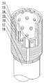
- the primary screen includes a base tube having a plurality of oil inlet holes on the outer wall, along the axial direction of the base tube a plurality of reinforcing ribs are disposed on the outer circumferential wall, and a winding wire is wound around the plurality of reinforcing ribs along the circular direction of the base pipe, and the adjacent two reinforcing ribs are filled with foam iron in a triangular block shape.
- the present invention divides the naked eye into three parts in the horizontal well through two outer packers, that is, the oil in the horizontal well respectively
- the two primary screens enter the pumping pipe; at this time, the oil entering from the two primary screens is transported to the upper part of the vertical section of the production casing through the end of the pumping pipe and the secondary screen on the horizontal section of the pumping pipe. In the middle, the section mining of the horizontal well is completed.
- the invention utilizes sectional mining to reduce the frictional resistance of the liquid produced at the toe end of the horizontal well, enlarge the production pressure difference of the toe end, increase the frictional resistance of the horizontal well and the production fluid, and reduce the production pressure of the heel end.
- Poor the horizontal production of the liquid is relatively evenly produced, effectively solving the uneven production of the horizontal section caused by the conventional horizontal well completion method, and even the toe end
- the problem of non-liquid production is to achieve balanced production of horizontal sections and improve the development of horizontal wells.
- the oil in the open hole near the end of the production casing passes through the primary screen and the secondary screen to filter, so that the solid phase content of the oil finally entering the pumping pipe is minimized, and the horizontal completion is washed in the later stage of oil recovery.
- the washing fluid is injected into the production casing, and the oil suction pipe, the primary sieve pipe and the secondary sieve pipe are cleaned by the washing fluid to ensure the oil recovery efficiency of the horizontal completion in the later mining process;
- the base pipe is placed in the horizontal section of the horizontal completion, and the heavy oil enters the gap formed between the wire and the casing through the wire gap, and after passing through the filtering action of the foam iron, enters the inside of the base pipe through the oil inlet hole.
- steam flooding technology is adopted in the mining of heavy oil, that is, a steam injection well and a production well are arranged above the oil reservoir, and steam is continuously passed through the steam injection well, so that the steam continuously Heating the formation around the wellbore, while the crude oil in the formation is also heated, forming a vapor zone that gradually expands with the continuous injection of steam in the formation near the wellbore, and the steam can reduce the saturation in the steam zone to a lower degree.
- the flowable crude oil ie, the difference between the original oil saturation and the residual oil saturation
- the steam moves strongly upwards, while in gravity Driven, the heated crude oil drive is tilted downwards, and as the temperature of the crude oil increases, the mixture of oil and water and gravel in the horizontal section of the horizontal completion will boil, causing the crude oil to be ablated (due to the mixture The disturbance caused by Teng), the mixture of oil, water and solid phase begins to enter the inside of the base pipe from the horizontal completion horizontal section, the wire is a complete metal rod and is wound on a plurality of reinforcing ribs by spacing to form a pair Primary filtration unit of large diameter solid phase such as gravel in oil water, while foamed iron forms secondary filtration unit for small diameter solid phase to achieve sand control of base pipe; and, when it is subjected to liquid pressure in the horizontal section of horizontal completion And when the oil and water itself carries the influence of heat and causes the production pressure to
- a lost hand that is connected to the upper end of the packer by a thread. After the hand is connected to the packer, it can be directly connected with the pumping string in the technical casing. At the same time, the packer separates the vertical part of the first section of the oil pipe into upper and lower parts, and the oil hole is opened in the lower part. The hand is located at the upper part, so that the product fluid flowing in the first stage of the primary screen is directly mixed with the liquid phase flowing in from the second section of the oil pipe after flowing into the oil hole, and is concentrated in the hand and is taken out of the well. outer.
- a plurality of reinforcing ribs are also included, and a plurality of the reinforcing ribs are axially and annularly distributed on the winding wire along the base pipe.
- the wire In the horizontal section of the horizontal completion, the wire is not only subjected to the pressure of the oil layer, but the pressure changes with the change of the temperature of the oil layer, that is, during the sudden change of the pressure, the wire is extremely vulnerable, and the present invention passes A plurality of annularly distributed reinforcing ribs are arranged on the wire so that the primary filtering unit formed by the winding wire is stably supported to cope with the ever-changing production pressure in the horizontal section of the horizontal completion and to prolong its own service life.
- a TiALN-WC/C layer is coated on the outer wall of the wire.
- the TiALN-WC/C coating is provided on the outer wall of the wire, and the friction coefficient of the TiALN-WC/C coating is only 0.1.
- Friction loss, and self-lubricating, greatly guarantees the service life of the wire in the horizontal completion.
- the connector further includes a connector, and the two ends of the base pipe are respectively connected to the blind pipe through the connector.
- the base pipe is connected to the blind pipe through the connecting head to facilitate the pumping of the crude oil, and the traditional blind pipe and the base pipe are directly welded during the laying, so as to facilitate the direct damage of the wire wound Replacing the wire without replacing the base pipe and the wire as a whole, reducing the production cost of heavy oil mining.
- the present invention has the following advantages and beneficial effects:
- the oil in the open hole near the end of the production sleeve of the invention is filtered through the primary screen and the secondary screen, so that the solid phase content of the oil finally entering the pumping pipe is minimized, and the horizontal completion is performed in the late stage of oil recovery.
- the washing fluid is injected into the production casing, and the oil suction pipe, the primary sieve pipe and the secondary sieve pipe are cleaned by the washing fluid to ensure the oil recovery efficiency of the horizontal completion in the later mining process.
- Figure 1 is a schematic structural view of the present invention
- Figure 2 is a schematic structural view of a primary screen
- Figure 3 is a longitudinal cross-sectional view of the primary screen.
- 1-production casing 2-casing, 3-tube outer packer, 4-primary screen, 5-handle, 6-packer, 7-oil pipe, 8-in-tube packer, 9- Open-hole, 10-technical casing, 11-second screen, A-heel, B-toe, 12-rib, 13-winding, 14-rib, 15-base, 16-inlet , 17-joint, 18-blind tube, 19-foam iron.
- the present embodiment comprises an L-shaped production casing 2, the horizontal section of which is connected to two primary screens, and the casing 2 is arranged between the two primary screens.
- An L-shaped oil suction pipe 7 is fixed in the vertical section of the production casing 2 by a packer 6, and an inner pipe packer 8 is installed in the casing 2, and the horizontal end of the oil suction pipe 7 is two
- the horizontal screen formed by the primary screen and the casing 2 is freely extended, and the horizontal section of the oil suction pipe 7 is provided with a secondary screen 11 which is opposite to the horizontal section of the production casing 2
- two outboard packers 3 are mounted outside the casing 2, and two of the outboard packers 3 divide the open eye 9 into three parts;
- the primary screen 4 comprises an outer wall
- a base pipe 15 having a plurality of oil inlet holes 16 is provided, and a plurality of reinforcing ribs 14 are disposed on the outer circumferential wall thereof along the axial direction of the base pipe 15, and a plurality of the rein
- the present invention divides the naked eye 9 into three parts in the horizontal well through the two outer tube packers 3, namely The oil in the horizontal well enters the pumping pipe 7 through two primary screens respectively; at this time, the oil entering from the two primary screens passes through the end of the oil suction pipe 7 and the secondary screen 11 on the horizontal section of the oil suction pipe 7, respectively.
- the invention utilizes the sectional mining to reduce the frictional resistance of the liquid produced at the toe end of the horizontal well, enlarges the production pressure difference of the toe end B, and increases the frictional resistance of the horizontal well A and the liquid A, and reduces the friction.
- the production pressure difference with the end A achieves a relatively uniform output of the horizontal section of the production fluid, effectively solving the conventional horizontal well completion method.
- the resulting horizontal section produces uneven liquid production, and even the problem of non-liquid production at the toe end B, achieving balanced production of the horizontal section and improving the development effect of the horizontal well.
- the oil in the open hole 9 near the end of the production casing 2 is filtered through the primary screen and the secondary screen 11, so that the solid phase content of the oil finally entering the suction pipe 7 is minimized, and at the later stage of the oil recovery.
- the washing fluid is injected into the production casing 2, and the oil sucking pipe 7, the primary screen and the secondary screen 11 are cleaned by the washing fluid to ensure the horizontal completion in the later mining process. Oil recovery efficiency;
- the base pipe 15 is placed in the horizontal section of the horizontal completion, and the heavy oil enters the gap formed between the wire 13 and the casing through the gap of the wire 13 and passes through the oil inlet hole 16 after filtering by the foam iron 19.
- the steam flooding technology is adopted in the mining of the heavy oil, that is, the steam injection well and the production well are arranged above the oil reservoir, and continuously in the steam injection well
- the steam continuously heats the formation around the wellbore, and the crude oil in the formation is also heated, forming a vapor zone that gradually expands with the continuous injection of steam in the formation near the wellbore, and the steam can contain the saturation in the steam zone.
- a foamed iron 19 in the form of a triangular block after the deformation of the foamed iron 19, a plurality of flow paths of irregular geometry are formed in the secondary filtration interval for the passage of the oil-water mixture, and the foamed iron 19 is The pore force is slightly changed and is not easily blocked.
- the foam iron 19 has a certain elasticity, and the pores in the foam iron 19 are reset when the elastic deformation is restored, so as to maintain the seepage capacity in the secondary filtration interval and ensure the heavy oil. Smooth mining.
- This embodiment further includes a lost hand 5, which is connected to the upper end of the packer 6 by a thread.
- the lost hand 5 After the lost hand 5 is connected with the packer 6, it can directly interface with the sucker 7 column in the technical casing 10, and the packer 6 blocks the vertical portion of the first section of the oil pipe into upper and lower parts.
- the oil hole is opened at the lower part, and the hand 5 is located at the upper portion, so that the product liquid flowing in the first stage primary sieve tube is directly mixed with the liquid phase flowing in from the second stage oil pipe after being flowed into the oil hole, and concentrated in After losing the hand 5, he was taken out of the well.
- the embodiment further includes a plurality of reinforcing ribs 12, and a plurality of the reinforcing ribs 12 are axially and annularly distributed on the winding wire 13 along the base pipe 15.
- the wire 13 is not only subjected to the pressure of the oil layer, but the pressure changes with the change of the temperature of the oil layer, that is, during the sudden change of the pressure, the wire 13 is extremely susceptible to damage, and the present invention
- the primary filtering unit formed by the winding wire 13 is stably supported to cope with the ever-changing production pressure in the horizontal section of the horizontal completion, while extending its own Service life.
- a TiALN-WC/C coating is provided on the outer wall of the wire 13 and
- the TiALN-WC/C coating has a friction coefficient of only 0.1.
- the friction loss between the two can be greatly reduced, and the self-lubricating property is greatly ensured. Service life in horizontal completions.
- the base pipe 15 is connected to the blind pipe 18 through the joint head 17 to facilitate the pumping of the crude oil, and the conventional blind pipe 18 and the base pipe 15 are directly welded at the time of laying, so as to facilitate When the wire 13 is damaged, the wire 13 is directly replaced without replacing the base pipe 15 and the wire 13 as a whole, thereby reducing the production cost of heavy oil mining.
Landscapes
- Engineering & Computer Science (AREA)
- Mining & Mineral Resources (AREA)
- Geology (AREA)
- Life Sciences & Earth Sciences (AREA)
- Fluid Mechanics (AREA)
- Environmental & Geological Engineering (AREA)
- Physics & Mathematics (AREA)
- General Life Sciences & Earth Sciences (AREA)
- Geochemistry & Mineralogy (AREA)
- Chemical & Material Sciences (AREA)
- Dispersion Chemistry (AREA)
- Fats And Perfumes (AREA)
- Filtration Of Liquid (AREA)
Abstract
一种稠油水平井热采用的生产管柱,包括生产套管(1),生产套管的水平段连接有两个初级筛管(4),在生产套管竖直段内通过封隔器(6)固定有抽油管(7),抽油管的水平端在两个初级筛管以及套管(2)构成的水平井段自由延伸,抽油管的水平段上设置有二级筛管(11)。在水平井中,通过两个管外封隔器(3)使得裸眼被分割成三个部分,即水平井内的油液分别通过两个初级筛管进入抽油管周围;此时,由两个初级筛管内进入的油液分别经过抽油管末端以及抽油管水平段上的二级筛管被输送至生产套管竖直段上部中,进而完成水平井的分段开采。
Description
本发明属于水平井采油技术领域,尤其涉及一种稠油水平井热采用的生产管柱。
稠油是石油烃类能源中的重要组成部分,其特点如下:
(1)稠油中的胶质与沥青含量高,轻质馏分很少。而且随着胶质和沥青质
含量增高稠油的相对密度和粘度也相应增加。
(2)稠油的粘度对于温度特别敏感,随着温度的增加,粘度急剧下降。且原油粘度越大,这种变化越明显。
(3)稠油中硫、氧、氮等杂原子较多。
(4)稠油中石蜡含量一般较低,但也有极少数油田是“双高油田”,即沥青质含量高、石蜡含量也高,表征为高粘度高凝点原油。
(5)同一稠油油藏,原油性质在垂向油层的不同井段及平面上各井之间常常有很大的差别。
随着水平井钻完井和开采技术的不断完善,水平井有利于提高单井产量、增加可采储量和提高油田采收率,目前水平井开发技术应用于各种类型的油藏。对于均质的砂岩或者碳酸盐岩油藏而言,传统的裸眼完井、初级筛管完井、射孔完井方式会给水平井开发带来一些问题。由于生产水平段较长,受井筒沿程摩阻的影响,整个水平段的生产压差不同,跟端生产压差最大,趾端生产压差最小,最终导致水平段产液不均匀,甚至出现趾端不产液的情况,极大影响了水平井的开发效果。
发明内容
本发明在于提供一种稠油水平井热采用的生产管柱,减小跟端的生产压差,放大趾端的生产压差,实现水平段相对均匀地产出,从而实现水平井分段开采。
本发明的通过下述技术方案实现:
一种稠油水平井热采用的生产管柱,包括L形的生产套管,所述生产套管的水平段连接有两个初级筛管,套管设置在两个初级筛管之间,在所述生产套管竖直段内通过封隔器固定有L形的抽油管,在套管内安装有管内封隔器,所述抽油管的水平端在两个所述初级筛管以及套管构成的水平井段自由延伸,抽油管的水平段上设置有二级筛管,所述二级筛管正对端部与生产套管水平段连接的初级筛管,在套管外安装有两个管外封隔器,且两个所述管外封隔器将裸眼分隔成三部分;所述初级筛管包括外壁上开有多个进油孔的基管,沿所述基管轴向在其外圆周壁上设置有多个加强肋,且沿基管圆向在多个所述加强肋上间隔绕制有绕丝,相邻的两个加强肋之间填充有呈三角块状的泡沫铁。
现有技术中,在稠油的热采过程中,水平井的水平段越长,水平井趾端的沿程摩阻越大,最终导致水平段的产液不均匀,即水平段的跟端与趾端生产压差不相同,严重影响水平井的采油效率,针对此问题,本发明在水平井中,通过两个管外封隔器使得裸眼被分割成三个部分,即水平井内的油液分别通过两个初级筛管进入抽油管周围;此时,由两个初级筛管内进入的油液分别经过抽油管末端以及抽油管水平段上的二级筛管被输送至生产套管竖直段上部中,进而完成水平井的分段开采。本发明利用分段开采,使得位于水平井趾端产液的摩阻减小,放大了趾端的生产压差,同时增大了水平井跟端产液的摩阻,减小了跟端的生产压差,实现了水平段产液相对均匀地产出,有效解决了常规水平井完井方式所造成的水平段产液不均匀、甚至出现趾端
不产液的问题,实现水平段均衡产液,提高水平井的开发效果。并且靠近生产套管末端的裸眼中的油液通过初级筛管以及二级筛管的过滤,使得最终进入到抽油管中油液的固相含量降至最低,而在采油后期对水平完井进行洗井作业时,在生产套管内注入洗井液,通过洗井液对抽油管、初级筛管以及二级筛管进行清洗,保证水平完井在后期开采过程中的采油效率;
工作时,基管置于水平完井的水平段,稠油通过绕丝间隙进入到绕丝与套管形成的间隙中,在经过泡沫铁的过滤作用后,经过进油孔进入到基管内部,以实现油液的泵送;现有技术中,在对稠油进行开采时采用蒸汽驱技术,即在油藏上方设置注汽井和生产井,在注汽井中不断通过蒸汽,使得蒸汽不断加热井筒周围的地层,同时地层中的原油也被加热,在井筒附近的地层中形成随蒸汽的不断注入而逐步扩展的蒸汽带,蒸汽可将蒸汽带中的含饱和度降到较低的程度,并将可流动原油(即原始含油饱和度与残余油饱和度的差值)驱出蒸汽带;与此同时,在水平完井的水平段中,蒸汽强烈地向上倾方向运动,而在重力驱动下,把受热原油驱向下倾反向,而随着原油的温度的增加,水平完井水平段内的油水以及砂砾等混合物将沸腾,引起原油被剥蚀(因混合物的沸腾所引起的扰动),油水以及固相的混合物开始由水平完井水平段中进入到基管内部,绕丝为一根完整的金属棒且通过间隔绕制在多个加强肋上,形成对油水中砂砾等大直径固相的初级过滤单元,而泡沫铁则形成对小直径固相的二次过滤单元,以实现基管的防砂目的;并且,在当水平完井水平段内受到液体压力以及油水自身携带热量影响而发生导致生产压力变化时,相邻的两个加强肋之间形
成的二次过滤区间被压缩,但是在该二次过滤区间内填充有多个呈三角块状的泡沫铁,泡沫铁在受力发生形变后,在二次过滤区间内仍会形成多个不规则几何图形的流道以供油水混合物通过,并且泡沫铁内孔道受力发生微小变化而不容易被堵死,同时泡沫铁具有一定的弹性,在回复弹性形变时泡沫铁内的孔道复位,以维持二次过滤区间内的渗流能力,保证稠油的顺利开采。
还包括丢手,所述丢手通过丝扣与封隔器上端连接。丢手与封隔器连接后可直接与技术套管内的抽油管柱进行对接,同时封隔器将第一段油管的竖直部封隔成上、下两个部分,而油孔开设在下部,丢手位于上部,使得由第一段初级筛管中流进的产液在流入油孔后,直接与由第二段油管中流入的产液相混合,集中在丢手内后被抽出井外。
还包括多个加强筋,多个所述加强筋沿所述基管轴向且呈环形分布在绕丝上。在水平完井的水平段内,绕丝不仅受到油层的压力,且该压力随油层温度的变化而时刻变化,即在压力的骤然变化过程中,绕丝极易受到损伤,而本发明通过在绕丝上设置多个呈环形分布的加强筋,使得绕丝所形成的初次过滤单元被稳定支撑,以应对水平完井中水平段内不断变化的生产压力,同时延长其自身的使用寿命。
在所述绕丝外壁上涂有TiALN-WC/C层。作为优选,在绕丝外壁设置TiALN-WC/C涂层,而TiALN-WC/C涂层的摩擦系数只有0.1,在砂粒等固相与绕丝不断接触时,可以极大降低两者间的摩擦损耗,并且带有自润滑性,极大地保证绕丝在水平完井中的使用寿命。
还包括连接头,所述基管的两端分别通过连接头与盲管连接。作
为优选,根据实际采油的需要,将基管通过连接头与盲管连接,方便原油的泵送,并且在铺设时摒弃传统盲管与基管直接焊接的方式,以方便在绕丝损坏时直接更换绕丝而不用对基管、绕丝进行整体更换,降低稠油开采的生产成本。
本发明与现有技术相比,具有如下的优点和有益效果:
本发明靠近生产套管末端的裸眼中的油液通过初级筛管以及二级筛管的过滤,使得最终进入到抽油管中油液的固相含量降至最低,而在采油后期对水平完井进行洗井作业时,在生产套管内注入洗井液,通过洗井液对抽油管、初级筛管以及二级筛管进行清洗,保证水平完井在后期开采过程中的采油效率。
此处所说明的附图用来提供对本发明实施例的进一步理解,构成本申请的一部分,并不构成对本发明实施例的限定。在附图中:
图1为本发明结构示意图;
图2为初级筛管的结构示意图;
图3为初级筛管的纵向截面图。
附图中标记及相应的零部件名称:
1-生产套管、2-套管、3-管外封隔器、4-初级筛管、5-丢手、6-封隔器、7-抽油管、8-管内封隔器、9-裸眼、10-技术套管、11-二级筛管、A-跟端、B-趾端、12-加强筋、13-绕丝、14-加强肋、15-基管、16-进油孔、17-连接头、18-盲管、19-泡沫铁。
为使本发明的目的、技术方案和优点更加清楚明白,下面结合实施例和附图,对本发明作进一步的详细说明,本发明的示意性实施方
式及其说明仅用于解释本发明,并不作为对本发明的限定。
实施例1
如图1至图3所示,本实施例包括L形的生产套管2,所述生产套管2的水平段连接有两个初级筛管,套管2设置在两个初级筛管之间,在所述生产套管2竖直段内通过封隔器6固定有L形的抽油管7,在套管2内安装有管内封隔器8,所述抽油管7的水平端在两个所述初级筛管以及套管2构成的水平井段自由延伸,抽油管7的水平段上设置有二级筛管11,所述二级筛管11正对端部与生产套管2水平段连接的初级筛管,在套管2外安装有两个管外封隔器3,且两个所述管外封隔器3将裸眼9分隔成三部分;所述初级筛管4包括外壁上开有多个进油孔16的基管15,沿所述基管15轴向在其外圆周壁上设置有多个加强肋14,且沿基管15圆向在多个所述加强肋14上间隔绕制有绕丝13,相邻的两个加强肋14之间填充有呈三角块状的泡沫铁19。
现有技术中,在稠油的热采过程中,水平井的水平段越长,水平井趾端B的沿程摩阻越大,最终导致水平段的产液不均匀,即水平段的跟端A与趾端B生产压差不相同,严重影响水平井的采油效率,针对此问题,本发明在水平井中,通过两个管外封隔器3使得裸眼9被分割成三个部分,即水平井内的油液分别通过两个初级筛管进入抽油管7周围;此时,由两个初级筛管内进入的油液分别经过抽油管7末端以及抽油管7水平段上的二级筛管11被输送至生产套管2竖直段上部中,进而完成水平井的分段开采。本发明利用分段开采,使得位于水平井趾端B产液的摩阻减小,放大了趾端B的生产压差,同时增大了水平井跟端A产液的摩阻,减小了跟端A的生产压差,实现了水平段产液相对均匀地产出,有效解决了常规水平井完井方式所
造成的水平段产液不均匀、甚至出现趾端B不产液的问题,实现水平段均衡产液,提高水平井的开发效果。并且靠近生产套管2末端的裸眼9中的油液通过初级筛管以及二级筛管11的过滤,使得最终进入到抽油管7中油液的固相含量降至最低,而在采油后期对水平完井进行洗井作业时,在生产套管2内注入洗井液,通过洗井液对抽油管7、初级筛管以及二级筛管11进行清洗,保证水平完井在后期开采过程中的采油效率;
工作时,基管15置于水平完井的水平段,稠油通过绕丝13间隙进入到绕丝13与套管形成的间隙中,在经过泡沫铁19的过滤作用后,经过进油孔16进入到基管15内部,以实现油液的泵送;现有技术中,在对稠油进行开采时采用蒸汽驱技术,即在油藏上方设置注汽井和生产井,在注汽井中不断通过蒸汽,使得蒸汽不断加热井筒周围的地层,同时地层中的原油也被加热,在井筒附近的地层中形成随蒸汽的不断注入而逐步扩展的蒸汽带,蒸汽可将蒸汽带中的含饱和度降到较低的程度,并将可流动原油(即原始含油饱和度与残余油饱和度的差值)驱出蒸汽带;与此同时,在水平完井的水平段中,蒸汽强烈地向上倾方向运动,而在重力驱动下,把受热原油驱向下倾反向,而随着原油的温度的增加,水平完井水平段内的油水以及砂砾等混合物将沸腾,引起原油被剥蚀(因混合物的沸腾所引起的扰动),油水以及固相的混合物开始由水平完井水平段中进入到基管15内部,绕丝13为一根完整的金属棒且通过间隔绕制在多个加强肋14上,形成对油水中砂砾等大直径固相的初级过滤单元,而泡沫铁19则形成对小直径固相的二次过滤单元,以实现基管15的防砂目的;并且,在当水平完井
水平段内受到液体压力以及油水自身携带热量影响而发生导致生产压力变化时,相邻的两个加强肋14之间形成的二次过滤区间被压缩,但是在该二次过滤区间内填充有多个呈三角块状的泡沫铁19,泡沫铁19在受力发生形变后,在二次过滤区间内仍会形成多个不规则几何图形的流道以供油水混合物通过,并且泡沫铁19内孔道受力发生微小变化而不容易被堵死,同时泡沫铁19具有一定的弹性,在回复弹性形变时泡沫铁19内的孔道复位,以维持二次过滤区间内的渗流能力,保证稠油的顺利开采。
本实施例还包括丢手5,所述丢手5通过丝扣与封隔器6上端连接。丢手5与封隔器6连接后可直接与技术套管10内的抽油管7柱进行对接,同时封隔器6将第一段油管的竖直部封隔成上、下两个部分,而油孔开设在下部,丢手5位于上部,使得由第一段初级筛管中流进的产液在流入油孔后,直接与由第二段油管中流入的产液相混合,集中在丢手5内后被抽出井外。
本实施例还包括多个加强筋12,多个所述加强筋12沿所述基管15轴向且呈环形分布在绕丝13上。在水平完井的水平段内,绕丝13不仅受到油层的压力,且该压力随油层温度的变化而时刻变化,即在压力的骤然变化过程中,绕丝13极易受到损伤,而本发明通过在绕丝13上设置多个呈环形分布的加强筋12,使得绕丝13所形成的初次过滤单元被稳定支撑,以应对水平完井中水平段内不断变化的生产压力,同时延长其自身的使用寿命。
作为优选,在绕丝13外壁设置TiALN-WC/C涂层,而
TiALN-WC/C涂层的摩擦系数只有0.1,在砂粒等固相与绕丝13不断接触时,可以极大降低两者间的摩擦损耗,并且带有自润滑性,极大地保证绕丝13在水平完井中的使用寿命。
作为优选,根据实际采油的需要,将基管15通过连接头17与盲管18连接,方便原油的泵送,并且在铺设时摒弃传统盲管18与基管15直接焊接的方式,以方便在绕丝13损坏时直接更换绕丝13而不用对基管15、绕丝13进行整体更换,降低稠油开采的生产成本。
以上所述的具体实施方式,对本发明的目的、技术方案和有益效果进行了进一步详细说明,所应理解的是,以上所述仅为本发明的具体实施方式而已,并不用于限定本发明的保护范围,凡在本发明的精神和原则之内,所做的任何修改、等同替换、改进等,均应包含在本发明的保护范围之内。
Claims (5)
- 一种稠油水平井热采用的生产管柱,包括L形的生产套管(1),其特征在于:所述生产套管(1)的水平段连接有两个初级筛管(4),套管(2)设置在两个初级筛管(4)之间,在所述生产套管(1)竖直段内通过封隔器(6)固定有L形的抽油管(7),在套管(2)内安装有管内封隔器(8),所述抽油管(7)的水平端在两个所述初级筛管(4)以及套管(2)构成的水平井段自由延伸,抽油管(7)的水平段上设置有二级筛管(11),所述二级筛管(11)正对端部与生产套管(1)水平段连接的初级筛管(4),在套管(2)外安装有两个管外封隔器(3),且两个所述管外封隔器(3)将裸眼(9)分隔成三部分;所述初级筛管(4)包括外壁上开有多个进油孔(16)的基管(15),沿所述基管(15)轴向在其外圆周壁上设置有多个加强肋(14),且沿基管(15)圆向在多个所述加强肋(14)上间隔绕制有绕丝(13),相邻的两个加强肋(14)之间填充有呈三角块状的泡沫铁(19)。
- 根据权利要求1所述的一种稠油水平井热采用的生产管柱,其特征在于:还包括丢手(5),所述丢手(5)通过丝扣与封隔器(6)上端连接。
- 根据权利要求1所述的一种稠油水平井热采用的生产管柱,其特征在于:还包括多个加强筋(12),多个所述加强筋(12)沿所述基管(15)轴向且呈环形分布在绕丝(13)上。
- 根据权利要求1所述的一种稠油水平井热采用的生产管柱,其特征在于:在所述绕丝(13)外壁上涂有TiALN-WC/C层。
- 根据权利要求1所述的一种稠油水平井热采用的生产管柱, 其特征在于:还包括连接头(17),所述基管(15)的两端分别通过连接头(17)与盲管(18)连接。
Applications Claiming Priority (2)
| Application Number | Priority Date | Filing Date | Title |
|---|---|---|---|
| CN201610309043.7A CN105863579A (zh) | 2016-05-11 | 2016-05-11 | 一种稠油水平井热采用的生产管柱 |
| CN201610309043.7 | 2016-05-11 |
Publications (1)
| Publication Number | Publication Date |
|---|---|
| WO2017193503A1 true WO2017193503A1 (zh) | 2017-11-16 |
Family
ID=56630726
Family Applications (1)
| Application Number | Title | Priority Date | Filing Date |
|---|---|---|---|
| PCT/CN2016/097425 WO2017193503A1 (zh) | 2016-05-11 | 2016-10-14 | 一种稠油水平井热采用的生产管柱 |
Country Status (2)
| Country | Link |
|---|---|
| CN (1) | CN105863579A (zh) |
| WO (1) | WO2017193503A1 (zh) |
Cited By (2)
| Publication number | Priority date | Publication date | Assignee | Title |
|---|---|---|---|---|
| CN111622749A (zh) * | 2020-04-14 | 2020-09-04 | 中国石油化工股份有限公司 | 稠油热采筛管完井水平井找水管柱及找水方法 |
| CN114790878A (zh) * | 2021-01-26 | 2022-07-26 | 中国石油天然气股份有限公司 | 裂缝性油藏蒸汽辅助重力泄油井下电预热方法及系统 |
Families Citing this family (1)
| Publication number | Priority date | Publication date | Assignee | Title |
|---|---|---|---|---|
| CN105863579A (zh) * | 2016-05-11 | 2016-08-17 | 四川行之智汇知识产权运营有限公司 | 一种稠油水平井热采用的生产管柱 |
Citations (11)
| Publication number | Priority date | Publication date | Assignee | Title |
|---|---|---|---|---|
| NO309395B1 (no) * | 1999-02-15 | 2001-01-22 | Kjartan Roaldsnes | Sandfilter til bruk i en brönn |
| CN203808949U (zh) * | 2014-03-27 | 2014-09-03 | 华源益海石油技术开发(北京)有限公司 | 水平井悬挂式防砂装置 |
| CN204941480U (zh) * | 2015-09-30 | 2016-01-06 | 成都北方石油勘探开发技术有限公司 | 可实现分段开采的水平井完井套管及其构成的管柱 |
| CN205154113U (zh) * | 2015-11-02 | 2016-04-13 | 中国石油化工集团公司 | 一种用于砂岩地层深井的防砂滤水管 |
| CN105863578A (zh) * | 2016-05-11 | 2016-08-17 | 四川行之智汇知识产权运营有限公司 | 一种可实现分段开采的水平井完井管柱 |
| CN105863579A (zh) * | 2016-05-11 | 2016-08-17 | 四川行之智汇知识产权运营有限公司 | 一种稠油水平井热采用的生产管柱 |
| CN105863590A (zh) * | 2016-05-11 | 2016-08-17 | 四川行之智汇知识产权运营有限公司 | 用于浅层稠油油藏的防砂管柱 |
| CN105863576A (zh) * | 2016-05-11 | 2016-08-17 | 四川行之智汇知识产权运营有限公司 | 一种可实现分段开采的防砂管柱 |
| CN105927164A (zh) * | 2016-05-11 | 2016-09-07 | 四川行之智汇知识产权运营有限公司 | 一种浅层稠油油藏完井管柱 |
| CN105927165A (zh) * | 2016-05-11 | 2016-09-07 | 四川行之智汇知识产权运营有限公司 | 一种稠油水平井完井管柱 |
| CN105952388A (zh) * | 2016-05-11 | 2016-09-21 | 四川行之智汇知识产权运营有限公司 | 可分段开采的稠油水平井完井管柱 |
Family Cites Families (6)
| Publication number | Priority date | Publication date | Assignee | Title |
|---|---|---|---|---|
| CN2178783Y (zh) * | 1993-12-23 | 1994-10-05 | 吕从容 | 带有金属过滤套的绕丝滤砂管 |
| US5829522A (en) * | 1996-07-18 | 1998-11-03 | Halliburton Energy Services, Inc. | Sand control screen having increased erosion and collapse resistance |
| CA2212840C (en) * | 1997-08-13 | 2002-03-26 | Calvin G. Bohme | Sand exclusion liner for use in a wellbore |
| CN103032039A (zh) * | 2011-09-30 | 2013-04-10 | 中国石油化工股份有限公司 | 一种大斜度井套管预充填防砂方法及其专用滤砂管 |
| CN102913211A (zh) * | 2012-10-30 | 2013-02-06 | 陕西高新能源发展有限公司 | 防砂筛管 |
| CN103939060B (zh) * | 2014-04-17 | 2017-09-12 | 江阴市星宇塑胶有限公司 | 一种携砾滤水管制备方法 |
-
2016
- 2016-05-11 CN CN201610309043.7A patent/CN105863579A/zh active Pending
- 2016-10-14 WO PCT/CN2016/097425 patent/WO2017193503A1/zh active Application Filing
Patent Citations (11)
| Publication number | Priority date | Publication date | Assignee | Title |
|---|---|---|---|---|
| NO309395B1 (no) * | 1999-02-15 | 2001-01-22 | Kjartan Roaldsnes | Sandfilter til bruk i en brönn |
| CN203808949U (zh) * | 2014-03-27 | 2014-09-03 | 华源益海石油技术开发(北京)有限公司 | 水平井悬挂式防砂装置 |
| CN204941480U (zh) * | 2015-09-30 | 2016-01-06 | 成都北方石油勘探开发技术有限公司 | 可实现分段开采的水平井完井套管及其构成的管柱 |
| CN205154113U (zh) * | 2015-11-02 | 2016-04-13 | 中国石油化工集团公司 | 一种用于砂岩地层深井的防砂滤水管 |
| CN105863578A (zh) * | 2016-05-11 | 2016-08-17 | 四川行之智汇知识产权运营有限公司 | 一种可实现分段开采的水平井完井管柱 |
| CN105863579A (zh) * | 2016-05-11 | 2016-08-17 | 四川行之智汇知识产权运营有限公司 | 一种稠油水平井热采用的生产管柱 |
| CN105863590A (zh) * | 2016-05-11 | 2016-08-17 | 四川行之智汇知识产权运营有限公司 | 用于浅层稠油油藏的防砂管柱 |
| CN105863576A (zh) * | 2016-05-11 | 2016-08-17 | 四川行之智汇知识产权运营有限公司 | 一种可实现分段开采的防砂管柱 |
| CN105927164A (zh) * | 2016-05-11 | 2016-09-07 | 四川行之智汇知识产权运营有限公司 | 一种浅层稠油油藏完井管柱 |
| CN105927165A (zh) * | 2016-05-11 | 2016-09-07 | 四川行之智汇知识产权运营有限公司 | 一种稠油水平井完井管柱 |
| CN105952388A (zh) * | 2016-05-11 | 2016-09-21 | 四川行之智汇知识产权运营有限公司 | 可分段开采的稠油水平井完井管柱 |
Cited By (3)
| Publication number | Priority date | Publication date | Assignee | Title |
|---|---|---|---|---|
| CN111622749A (zh) * | 2020-04-14 | 2020-09-04 | 中国石油化工股份有限公司 | 稠油热采筛管完井水平井找水管柱及找水方法 |
| CN114790878A (zh) * | 2021-01-26 | 2022-07-26 | 中国石油天然气股份有限公司 | 裂缝性油藏蒸汽辅助重力泄油井下电预热方法及系统 |
| CN114790878B (zh) * | 2021-01-26 | 2023-08-22 | 中国石油天然气股份有限公司 | 裂缝性油藏蒸汽辅助重力泄油井下电预热方法及系统 |
Also Published As
| Publication number | Publication date |
|---|---|
| CN105863579A (zh) | 2016-08-17 |
Similar Documents
| Publication | Publication Date | Title |
|---|---|---|
| WO2017193502A1 (zh) | 一种可实现分段开采的水平井完井管柱 | |
| WO2017028322A1 (zh) | 一种水平井分段压裂同井注采采油方法 | |
| WO2017193503A1 (zh) | 一种稠油水平井热采用的生产管柱 | |
| CN103939071B (zh) | 一种水平井蒸汽驱井网结构及蒸汽驱方法 | |
| CN101864921A (zh) | 水平井的完井、采油管柱及其完井、采油工艺 | |
| US20190178068A1 (en) | Inflow control device and system having inflow control device | |
| CN201705276U (zh) | 水平井的完井、采油管柱 | |
| US20110290503A1 (en) | Well completion for viscous oil recovery | |
| WO2017193500A1 (zh) | 水平完井稠油热采用筛管 | |
| WO2017193504A1 (zh) | 可分段开采的稠油水平井完井管柱 | |
| CN107313760B (zh) | 分层注汽改善稠油油藏开发效果的方法 | |
| CN104405355A (zh) | 水平井注采管柱 | |
| CN208137872U (zh) | 一种射流解堵管柱 | |
| WO2017193501A1 (zh) | 水平完井用的防砂筛管 | |
| CN106677747A (zh) | 一种水平井完井防砂用充填式控水筛管 | |
| CN105863576A (zh) | 一种可实现分段开采的防砂管柱 | |
| CN105927164A (zh) | 一种浅层稠油油藏完井管柱 | |
| CN105863590A (zh) | 用于浅层稠油油藏的防砂管柱 | |
| CN105971567A (zh) | 一种用于浅层稠油水平完井的筛管 | |
| CN104675373B (zh) | 一种水平井双管射流均匀注汽工艺及配套工具 | |
| Shengfei et al. | Application status and thinking of flow control devices in SAGD | |
| CN107002484A (zh) | 用于在井筒中使用的流入控制系统 | |
| CN105715245A (zh) | 低渗低压煤层气储层氮气饱和水力压裂工艺 | |
| US10018024B2 (en) | Steam operated injection and production device | |
| CN105756626A (zh) | 一种浅层油藏水平完井用防损筛管 |
Legal Events
| Date | Code | Title | Description |
|---|---|---|---|
| NENP | Non-entry into the national phase |
Ref country code: DE |
|
| 121 | Ep: the epo has been informed by wipo that ep was designated in this application |
Ref document number: 16901458 Country of ref document: EP Kind code of ref document: A1 |
|
| 122 | Ep: pct application non-entry in european phase |
Ref document number: 16901458 Country of ref document: EP Kind code of ref document: A1 |