WO2017191955A2 - 멀티 모드 송신기의 동작 방법 - Google Patents
멀티 모드 송신기의 동작 방법 Download PDFInfo
- Publication number
- WO2017191955A2 WO2017191955A2 PCT/KR2017/004604 KR2017004604W WO2017191955A2 WO 2017191955 A2 WO2017191955 A2 WO 2017191955A2 KR 2017004604 W KR2017004604 W KR 2017004604W WO 2017191955 A2 WO2017191955 A2 WO 2017191955A2
- Authority
- WO
- WIPO (PCT)
- Prior art keywords
- mode
- wireless power
- voltage value
- transmitter
- power
- Prior art date
- Legal status (The legal status is an assumption and is not a legal conclusion. Google has not performed a legal analysis and makes no representation as to the accuracy of the status listed.)
- Ceased
Links
Images





Classifications
-
- H—ELECTRICITY
- H02—GENERATION; CONVERSION OR DISTRIBUTION OF ELECTRIC POWER
- H02J—ELECTRIC POWER NETWORKS; CIRCUIT ARRANGEMENTS OR SYSTEMS FOR SUPPLYING OR DISTRIBUTING ELECTRIC POWER; SYSTEMS FOR STORING ELECTRIC ENERGY
- H02J50/00—Circuit arrangements or systems for wireless supply or distribution of electric power
- H02J50/10—Circuit arrangements or systems for wireless supply or distribution of electric power using inductive coupling
-
- H—ELECTRICITY
- H02—GENERATION; CONVERSION OR DISTRIBUTION OF ELECTRIC POWER
- H02J—ELECTRIC POWER NETWORKS; CIRCUIT ARRANGEMENTS OR SYSTEMS FOR SUPPLYING OR DISTRIBUTING ELECTRIC POWER; SYSTEMS FOR STORING ELECTRIC ENERGY
- H02J50/00—Circuit arrangements or systems for wireless supply or distribution of electric power
- H02J50/10—Circuit arrangements or systems for wireless supply or distribution of electric power using inductive coupling
- H02J50/12—Circuit arrangements or systems for wireless supply or distribution of electric power using inductive coupling of the resonant type
-
- H—ELECTRICITY
- H02—GENERATION; CONVERSION OR DISTRIBUTION OF ELECTRIC POWER
- H02J—ELECTRIC POWER NETWORKS; CIRCUIT ARRANGEMENTS OR SYSTEMS FOR SUPPLYING OR DISTRIBUTING ELECTRIC POWER; SYSTEMS FOR STORING ELECTRIC ENERGY
- H02J50/00—Circuit arrangements or systems for wireless supply or distribution of electric power
- H02J50/40—Circuit arrangements or systems for wireless supply or distribution of electric power using two or more transmitting or receiving devices
-
- H—ELECTRICITY
- H02—GENERATION; CONVERSION OR DISTRIBUTION OF ELECTRIC POWER
- H02J—ELECTRIC POWER NETWORKS; CIRCUIT ARRANGEMENTS OR SYSTEMS FOR SUPPLYING OR DISTRIBUTING ELECTRIC POWER; SYSTEMS FOR STORING ELECTRIC ENERGY
- H02J50/00—Circuit arrangements or systems for wireless supply or distribution of electric power
- H02J50/90—Circuit arrangements or systems for wireless supply or distribution of electric power involving detection or optimisation of position, e.g. alignment
-
- H—ELECTRICITY
- H02—GENERATION; CONVERSION OR DISTRIBUTION OF ELECTRIC POWER
- H02J—ELECTRIC POWER NETWORKS; CIRCUIT ARRANGEMENTS OR SYSTEMS FOR SUPPLYING OR DISTRIBUTING ELECTRIC POWER; SYSTEMS FOR STORING ELECTRIC ENERGY
- H02J7/00—Circuit arrangements for charging or discharging batteries or for supplying loads from batteries
- H02J7/02—Circuit arrangements for charging or discharging batteries or for supplying loads from batteries for charging batteries from AC mains by converters
-
- H—ELECTRICITY
- H02—GENERATION; CONVERSION OR DISTRIBUTION OF ELECTRIC POWER
- H02J—ELECTRIC POWER NETWORKS; CIRCUIT ARRANGEMENTS OR SYSTEMS FOR SUPPLYING OR DISTRIBUTING ELECTRIC POWER; SYSTEMS FOR STORING ELECTRIC ENERGY
- H02J7/00—Circuit arrangements for charging or discharging batteries or for supplying loads from batteries
- H02J7/90—Regulation of charging or discharging current or voltage
- H02J7/971—Regulation of charging or discharging current or voltage the charge cycle being controlled or terminated in response to non-electric parameters
-
- H—ELECTRICITY
- H04—ELECTRIC COMMUNICATION TECHNIQUE
- H04B—TRANSMISSION
- H04B5/00—Near-field transmission systems, e.g. inductive or capacitive transmission systems
- H04B5/70—Near-field transmission systems, e.g. inductive or capacitive transmission systems specially adapted for specific purposes
- H04B5/79—Near-field transmission systems, e.g. inductive or capacitive transmission systems specially adapted for specific purposes for data transfer in combination with power transfer
Definitions
- the present invention relates to a wireless power transmission technology, and more particularly, to a method of operating a multi-mode transmitter capable of simultaneously transmitting wireless power in an electromagnetic resonance method and an electromagnetic induction method.
- Wireless power transmission or wireless energy transfer is a technology that transmits electrical energy wirelessly from a transmitter to a receiver using the principle of induction of magnetic field, which is already used by electric motors or transformers using the electromagnetic induction principle in the 1800s. Since then, there have been attempts to transmit electrical energy by radiating electromagnetic waves such as high frequency, microwaves, and lasers. Electric toothbrushes and some wireless razors that we commonly use are actually charged with the principle of electromagnetic induction.
- energy transmission using wireless may be classified into magnetic induction, electromagnetic resonance, and RF transmission using short wavelength radio frequency.
- the magnetic induction method uses the phenomenon that magnetic flux generated at this time causes electromotive force to other coils when two coils are adjacent to each other and current flows to one coil, and is rapidly commercialized in small devices such as mobile phones. Is going on. Magnetic induction is capable of transmitting power of up to several hundred kilowatts (kW) and has high efficiency, but the maximum transmission distance is less than 1 centimeter (cm).
- the magnetic resonance method is characterized by using an electric or magnetic field instead of using electromagnetic waves or current. Since the magnetic resonance method is hardly affected by the electromagnetic wave problem, it has the advantage of being safe for other electronic devices or the human body. On the other hand, it can be utilized only in limited distances and spaces, and has a disadvantage in that energy transmission efficiency is rather low.
- the short wavelength wireless power transmission scheme implies, the RF transmission scheme— takes advantage of the fact that energy can be transmitted and received directly in the form of RadioWave.
- This technology is a wireless power transmission method of the RF method using a rectenna, a compound word of an antenna and a rectifier (rectifier) refers to a device that converts RF power directly into direct current power.
- the RF method is a technology that converts AC radio waves to DC and uses them. Recently, research on commercialization has been actively conducted as efficiency is improved.
- Wireless power transfer technology can be used in various industries, such as the mobile, IT, railroad and consumer electronics industries.
- a multi-mode transmitter capable of simultaneously transmitting power in an electromagnetic resonance mode and an electromagnetic induction mode among the wireless power transmitters, when another mode is also activated and transmits power in a specific mode without any preparation, overvoltage, It may cause over current and over power, which may damage the receiver.
- the present invention has been devised to solve the above-mentioned problems of the prior art, and an object of the present invention is to provide a method of operating a multi-mode transmitter.
- Another object of the present invention is to provide a method of operating a multi-mode transmitter capable of optimizing a wireless power transmission mode when transmission efficiency decreases during power transmission in a specific mode.
- the present invention can provide a method of operating a multi-mode transmitter.
- An operation method of a multi-mode transmitter for wirelessly transmitting power simultaneously in an electromagnetic resonance mode and an electromagnetic induction mode may include determining whether switching of the wireless power transmission mode is required during wireless charging according to the first mode. Determining; When switching of the wireless power transfer mode is required, a first mode voltage value which is a voltage value of the first mode voltage in a state in which charging according to a first mode is normalized is stored, and the first mode voltage is stored as a minimum first mode voltage.
- the determining of whether the switching of the wireless power transfer mode is necessary may include: when the intensity of the output voltage of the receiver falls below a certain threshold or the wireless power transfer efficiency falls below a certain threshold, And determining that the switching of the wireless power transfer mode is necessary.
- the determining of the final wireless power transfer mode may include: determining the final wireless power transfer mode by the first mode when a result calculated based on the first mode voltage value and the second mode voltage value is smaller than the threshold voltage. And determining a simultaneous charging mode for simultaneously performing wireless power transfer and wireless power transfer in the second mode as the final wireless power transfer mode.
- the determining of the final wireless power transfer mode may include determining the final wireless power transfer mode when the first mode voltage value and the second mode voltage value are greater than or equal to the threshold voltage. And determining the wireless power transfer mode.
- the determining of the final wireless power transfer mode may include: when a result calculated based on the first mode voltage value and the second mode voltage value is greater than or equal to the threshold voltage, the transmission efficiency of the first mode And determining a mode capable of delivering higher power or having a higher power transmission efficiency as the final wireless power transmission mode based on the transmission efficiency of the second mode.
- the determining of the final wireless power transfer mode may include: determining whether the final wireless power transfer mode is based on the first mode voltage value and the second mode voltage value. Determining a simultaneous charging mode that simultaneously performs power transfer and wireless power transfer by the second mode as the final wireless power transfer mode, wherein the threshold voltage value of the first mode voltage and the first mode is determined from the threshold voltage. Subtracting the value multiplied by the transmission efficiency; Calculating an adjusted second mode voltage value, which is a value obtained by dividing the subtracted result by the transmission efficiency of the second mode; Restoring the first mode voltage to the first mode voltage value; And lowering the second mode voltage to the adjusted second mode voltage value to perform wireless power transmission according to the second mode.
- the minimum first mode voltage may be a minimum voltage value such that the power transmission by the first mode is not interrupted and the communication channel is not disconnected.
- the threshold voltage may be a threshold voltage value at which the voltage applied to the load of the receiver becomes an excess voltage.
- the result of calculating based on the first mode voltage value and the second mode voltage value is a value obtained by multiplying the first mode voltage value and the transmission efficiency of the first mode, a second mode voltage value, and It may be the result of summing a value obtained by multiplying the transmission efficiency of the second mode.
- a method of operating a multi-mode transmitter for wirelessly transmitting power simultaneously in an electromagnetic resonance mode and an electromagnetic induction mode may include whether switching of the wireless power transfer mode is required during wireless charging according to the first mode. Determining; When switching of the wireless power transmission mode is required, transmitting a signal for wireless power transmission according to a second mode and receiving a feedback signal corresponding to the signal; Determining a reception efficiency of a receiver based on the feedback signal; Determining a second mode predicted voltage value, which is a voltage value of a second mode voltage expected in a state where charging according to the second mode is normalized based on the feedback signal; Determining a final wireless power transfer mode by comparing a threshold voltage with a result calculated based on the first mode voltage value and the second mode predicted voltage value; And performing wireless charging according to the final wireless power transfer mode.
- the wireless power transmitter and the power control method thereof according to the present invention will be described below.
- the current wireless power transmission mode is completely changed before changing to another wireless power transmission mode.
- a method of operating a multi-mode transmitter when it is determined that the transmission efficiency is low while charging in one wireless power transmission mode, another wireless power transmission mode is completely changed before changing to another wireless power transmission mode.
- FIG. 1 is a block diagram illustrating a wireless charging system according to an embodiment of the present invention.
- FIG. 2 is a block diagram illustrating a structure of a wireless power transmitter supporting multi mode according to an embodiment of the present invention.
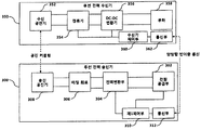
- FIG. 3 is a block diagram illustrating a structure of a resonant transmitter according to an embodiment of the present invention.
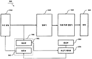
- FIG. 4 is a block diagram illustrating a structure of an induction transmitter according to an embodiment of the present invention.
- FIG. 5 is a block diagram illustrating a structure of a wireless power receiver interworking with the wireless power transmitter according to FIG. 4.
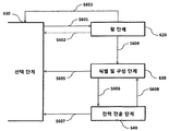
- FIG. 6 is a state transition diagram for explaining a wireless power transmission procedure defined in the WPC standard.
- FIG. 7 is a state transition diagram for explaining a wireless power transmission procedure defined in the PMA standard.
- FIG. 8 is a state transition diagram of a wireless power receiver supporting an electromagnetic resonance method according to an embodiment of the present invention.
- FIG. 9 is a state transition diagram illustrating a state transition procedure in the wireless power transmitter supporting the electric resonance method according to an embodiment of the present invention.
- FIG. 10 is a view for explaining a method of operation of a multi-mode transmitter according to an embodiment of the present invention.
- FIG. 11 is a view for explaining a method of operation of a multi-mode transmitter according to another embodiment of the present invention.
- FIG. 12 is a block diagram illustrating a structure of a multi-mode transmitter according to an embodiment of the present invention.
- a method of operating a multi-mode transmitter for wirelessly transmitting power simultaneously in an electromagnetic resonance mode and an electromagnetic induction mode determines whether wireless power transmission mode switching is required during wireless charging according to the first mode. Determining; When switching of the wireless power transfer mode is required, a first mode voltage value which is a voltage value of the first mode voltage in a state in which charging according to a first mode is normalized is stored, and the first mode voltage is stored as a minimum first mode voltage.
- the top (bottom) or the bottom (bottom) is the two components are in direct contact with each other or One or more other components are all included disposed between the two components.
- up (up) or down (down) may include the meaning of the down direction as well as the up direction based on one component.
- a device equipped with a function for transmitting wireless power on the wireless charging system is a wireless power transmitter, a wireless power transmitter, a wireless power transmitter, a wireless power transmitter, a transmitter, a transmitter, a transmitter for convenience of description.
- a transmitter side, a wireless power transmitter, a wireless power transmitter, and the like will be used interchangeably.
- a wireless power receiver, a wireless power receiver, a wireless power receiver, a wireless power receiver, a wireless power receiver, a receiver terminal, a receiver, Receivers, receivers and the like can be used interchangeably.
- the transmitter according to the present invention may be configured in a pad form, a cradle form, an access point (AP) form, a small base station form, a stand form, a ceiling buried form, a wall hanging form, and the like. You can also transfer power.
- the transmitter may comprise at least one wireless power transmission means.
- the wireless power transmission means may use various wireless power transmission standards based on an electromagnetic induction method that generates a magnetic field in the power transmitter coil and charges using the electromagnetic induction principle in which electricity is induced in the receiver coil under the influence of the magnetic field.
- the wireless power transmission means may include a wireless charging technology of the electromagnetic induction method defined by the Wireless Power Consortium (WPC) and the Power Matters Alliance (PMA) which is a wireless charging technology standard apparatus.
- WPC Wireless Power Consortium
- PMA Power Matters Alliance
- the receiver according to an embodiment of the present invention may be provided with at least one wireless power receiving means, and may simultaneously receive wireless power from two or more transmitters.
- the wireless power receiving means may include an electromagnetic induction wireless charging technology defined by the Wireless Power Consortium (WPC) and the Power Matters Alliance (PMA), which are wireless charging technology standard organizations.
- WPC Wireless Power Consortium
- PMA Power Matters Alliance
- the receiver according to the present invention is a mobile phone, smart phone, laptop computer, digital broadcasting terminal, PDA (Personal Digital Assistants), PMP (Portable Multimedia Player), navigation, MP3 player, electric It may be used in a small electronic device such as a toothbrush, an electronic tag, a lighting device, a remote control, a fishing bobber, a wearable device such as a smart watch, but is not limited thereto. If the device is equipped with a wireless power receiver according to the present invention, the battery can be charged. It is enough.
- FIG. 1 is a block diagram illustrating a wireless charging system according to an embodiment of the present invention.
- a wireless charging system includes a wireless power transmitter 10 that largely transmits power wirelessly, a wireless power receiver 20 that receives the transmitted power, and an electronic device 20 that receives the received power. Can be configured.
- the wireless power transmitter 10 and the wireless power receiver 20 may perform in-band communication for exchanging information using the same frequency band as the operating frequency used for wireless power transmission.
- the wireless power transmitter 10 and the wireless power receiver 20 perform out-of-band communication for exchanging information using a separate frequency band different from an operating frequency used for wireless power transmission. It can also be done.
- the information exchanged between the wireless power transmitter 10 and the wireless power receiver 20 may include control information as well as status information of each other.
- the status information and control information exchanged between the transmitting and receiving end will be more clear through the description of the embodiments to be described later.
- the in-band communication and the out-of-band communication may provide bidirectional communication, but are not limited thereto. In another embodiment, the in-band communication and the out-of-band communication may provide one-way communication or half-duplex communication.
- the unidirectional communication may be performed by the wireless power receiver 20 only transmitting information to the wireless power transmitter 10, but is not limited thereto.
- the wireless power transmitter 10 may transmit information to the wireless power receiver 20. It may be to transmit.
- bidirectional communication between the wireless power receiver 20 and the wireless power transmitter 10 is possible, but at one time, only one device may transmit information.
- the wireless power receiver 20 may obtain various state information of the electronic device 30.
- the state information of the electronic device 30 may include current power usage information, information for identifying a running application, CPU usage information, battery charge status information, battery output voltage / current information, and the like.
- the information may be obtained from the electronic device 30 and may be utilized for wireless power control.
- the wireless power transmitter 10 may transmit a predetermined packet indicating whether to support fast charging to the wireless power receiver 20.
- the wireless power receiver 20 may notify the electronic device 30 when it is determined that the connected wireless power transmitter 10 supports the fast charging mode.
- the electronic device 30 may indicate that fast charging is possible through predetermined display means provided, for example, it may be a liquid crystal display.
- the user of the electronic device 30 may control the wireless power transmitter 10 to operate in the fast charge mode by selecting a predetermined fast charge request button displayed on the liquid crystal display.
- the electronic device 30 may transmit a predetermined quick charge request signal to the wireless power receiver 20.
- the wireless power receiver 20 may convert the normal low power charging mode into the fast charging mode by generating a charging mode packet corresponding to the received fast charging request signal to the wireless power transmitter 10.
- FIG. 2 is a block diagram illustrating a structure of a wireless power transmitter supporting multi mode according to an embodiment of the present invention.
- the wireless power transmitter 200 may correspond to the wireless power transmitter 10 shown in FIG. 1.
- the wireless power transmitter 200 may largely include an induction transmitter 210, a resonant transmitter 220, a main controller 230, and a mode selection switch 240. It is not limited to this.
- the mode selection switch 240 may be connected to the power source 205 so that power applied from the power source 205 may be transmitted to the induction transmitter 210 and / or the resonant transmitter 220 under the control of the main controller 230. It can provide the function of switching.
- the power source 205 may be a battery supplied through an external power terminal or mounted inside the wireless power transmitter 200.
- the induction transmitter 210 is a device for wirelessly transmitting power to a receiver by an electromagnetic induction method, and may operate according to a PMA or WPC standard. Detailed configuration and operation of the induction transmitter 210 will be described later with reference to FIGS. 4 to 5.
- the resonator transmitter 220 is a device for wirelessly transmitting power to the receiver in an electromagnetic resonance manner, and may operate according to the A4WP standard. Detailed configuration and operation of the resonant transmitter 220 will be described later with reference to FIG. 3.
- the main controller 230 may control the overall operation of the wireless power transmitter 200.
- the main controller 230 may adaptively determine the wireless power transmission mode based on the characteristics and status of the wireless power receiver, and control the mode selection switch 240 according to the determined wireless power transmission mode.
- the wireless power transmitter 200 is a multi-mode transmitter supporting both an electromagnetic induction method and an electromagnetic resonance method, and the multi-mode transmitter may provide a wireless charging service to a single mode receiver as well as a multi mode receiver. In this case, the multi-mode transmitter may transmit power to at least one receiver.
- the wireless charging mode selection and switching procedure between the multi-mode transmitter and the multi-mode receiver may be transparent to the user without any user intervention.
- the multi-mode transmitter may be classified into a first multi-mode transmitter and a second multi-mode transmitter according to whether the simultaneous power transmission is possible in the electromagnetic resonance method and the electromagnetic induction method.
- the first multi-mode transmitter may simultaneously transmit power in an electromagnetic resonance method and an electromagnetic induction method.
- the first multi-mode transmitter may transmit power to one receiver in an electromagnetic induction manner while simultaneously transmitting power to the plurality of receivers in an electromagnetic resonance method.
- the first multi-mode transmitter performs time division interleaving on a receiver detection procedure defined in an electromagnetic resonance method and an electromagnetic induction method, and establishes a session with a receiver detected in a wireless charging mode that detects the first receiver.
- the procedure can be initiated.
- the receiver detection procedure may be immediately terminated.
- the time and order of transmitting the receiver sensing signal for each wireless charging mode in the time division interleaving of the electromagnetic resonance method and the electromagnetic induction method for the receiver sensing are not limited, but are defined in the standard corresponding to each wireless charging mode. It should be defined to satisfy the time requirements.
- the first multi-mode transmitter may resume the receiver detection procedure.
- the first multi-mode transmitter may determine whether switching to the alternative mode is necessary. If it is determined that switching to the alternative mode is required, the first multi-mode transmitter performs a predetermined switching procedure to the alternative mode. On the other hand, when switching to the alternative mode is not necessary, the first multi-mode transmitter may maintain a current operation mode to provide a wireless charging service.
- the second multi-mode receiver While the first multi-mode transmitter is transmitting wireless power to one of the wireless charging modes, hereinafter referred to as the first wireless charging mode for convenience of description, the second multi-mode receiver enters the second wireless charging mode. If it is confirmed that the attempt to establish a session of the session with the second multi-mode receiver may be blocked.
- the second multi-mode transmitter may operate in only one wireless charging mode at any one time.
- the second multi-mode transmitter may perform a receiver sensing procedure according to a predefined rule.
- the receiver sensing procedure may be defined such that the receiver sensing procedure defined in each of the electromagnetic resonance method and the electromagnetic induction method is time division interleaving.
- each time division interleaved receiver sensing procedure must be defined to satisfy the time requirement of the receiver sensing procedure corresponding to the corresponding standard.
- the second multi-mode transmitter may not perform a receiver detection procedure for another wireless charging mode while transmitting wireless power in one wireless charging mode.
- the second multi-mode transmitter may resume the receiver sensing procedure when wireless charging to the corresponding receiver is completed or wireless power transmission is terminated.
- the second multi-mode transmitter may provide a predetermined user interface for allowing the user to identify the currently active wireless charging mode.
- the currently activated wireless charging mode may be displayed using LEDs having different colors, but this is only one embodiment, and another embodiment of the present invention is a liquid crystal mounted on the second multi-mode transmitter.
- the display may indicate the currently activated wireless charging mode.
- the first multi-mode transmitter and the second multi-mode transmitter may broadcast a predetermined transmitter multi-mode broadcast message for informing the receiver of the multi-mode capability.
- the transmitter multi-mode broadcast message may include information for identifying a supportable wireless charging mode, information on a power rating for each supportable wireless charging mode, and the like.
- the multi-mode transmitter may have different messages for receiving the charging state information of the receiver according to the activated wireless charging mode.
- the A4WP standard which is an electromagnetic resonance method, defines a PRU (Power Receiving Unit) Alert message for reporting to a transmitter that charging is completed.
- the PMA standard an electromagnetic induction method, defines an End of Charge (EOC) request message for reporting to the transmitter that charging is completed.
- the wireless power transmitter 200 will be described on the premise that the first multi-mode transmitter is used. As described above, the wireless power transmitter 200 adaptively determines the wireless power transmission mode based on characteristics and conditions of the wireless power receiver.
- the main controller 230 may supply the power 205 to the resonant transmitter 220.
- the mode selection switch 240 may be controlled to allow.
- the main controller 230 supplies the power 205 to the induction transmitter 210.
- the mode selection switch 240 can be controlled to be.
- the main controller 230 may supply power ( The mode selection switch 240 may be controlled so that 205 may be supplied to both the induction transmitter 210 and the resonant transmitter 220.
- the main controller 230 may perform wireless power. The optimal mode is selected from the two wireless power transmission modes based on the characteristics and conditions of the receiver, and the mode selection switch 240 is controlled to supply the power 205 to the transmitter 210 or 220 corresponding to the selected mode. can do.
- the main controller 230 supplies power to a transmitter corresponding to the newly determined mode.
- the mode selection switch 240 may be controlled to supply the 205.
- the main controller 230 may control the induction transmitter 210 and the resonant transmitter 220 to control the strength of the power signal transmitted through the coil.
- FIG. 3 is a block diagram illustrating a structure of a resonant transmitter according to an embodiment of the present invention.
- the wireless power transmission system may include a wireless power transmitter 300 and a wireless power receiver 350.
- the wireless power transmitter 300 may correspond to the resonant transmitter 220 shown in FIG. 2.
- the wireless power transmitter 300 transmits wireless power to one wireless power receiver 200, this is only one embodiment, and wireless power according to another embodiment of the present invention.
- the transmitter 300 may transmit wireless power to the plurality of wireless power receivers 350.
- the wireless power receiver 350 may simultaneously receive wireless power from the plurality of wireless power transmitters 300.
- the wireless power transmitter 300 may generate a magnetic field using a specific power transmission frequency to transmit power to the wireless power receiver 350.
- the wireless power receiver 350 may receive power by tuning to the same frequency as the frequency used by the wireless power transmitter 300.
- the frequency for power transmission may be a 6.78MHz band, but is not limited thereto.
- the power transmitted by the wireless power transmitter 300 may be transmitted to the wireless power receiver 350 that is in resonance with the wireless power transmitter 300.
- the maximum number of wireless power receivers 350 that can receive power from one wireless power transmitter 300 includes the maximum transmit power level of the wireless power transmitter 300, the maximum power reception level of the wireless power receiver 350, and the wireless. It may be determined based on the physical structures of the power transmitter 300 and the wireless power receiver 350.
- the wireless power transmitter 300 and the wireless power receiver 350 may perform bidirectional communication in a frequency band different from a frequency band for transmitting wireless power, that is, a resonant frequency band.
- the bidirectional communication may use a half-duplex Bluetooth Low Energy (BLE) communication protocol.
- BLE Bluetooth Low Energy
- the wireless power transmitter 300 and the wireless power receiver 350 may exchange characteristic and state information, that is, power negotiation information, with each other through the bidirectional communication.
- the wireless power receiver 350 may transmit predetermined power reception state information for controlling the power level received from the wireless power transmitter 300 to the wireless power transmitter 300 through bidirectional communication. 300 may dynamically control the transmit power level based on the received power reception state information. Through this, the wireless power transmitter 300 may not only optimize power transmission efficiency, but also prevent load damage due to over-voltage, and prevent unnecessary waste of power due to under-voltage. It can provide a function to.
- the wireless power transmitter 300 performs a function of authenticating and identifying the wireless power receiver 350 through two-way communication, a function of identifying an incompatible device or an unchargeable object, and a function of identifying a valid load. You may.
- the wireless power transmitter 300 includes a power supplier 302, a power conversion unit 304, a matching circuit 306, a transmission resonator 308, and a first control unit.
- the controller 310 may include a communication unit 312 and a communication unit 312.
- the power supply unit 302 may supply a specific supply voltage to the power conversion unit 304 under the control of the first control unit 310.
- the supply voltage may be a DC voltage or an AC voltage.
- the power conversion unit 304 may convert the voltage received from the power supply unit 302 into a specific voltage under the control of the first control unit 310.
- the power converter 304 may include at least one of a DC / DC converter, an AC / DC converter, and a power amplifier.
- the matching circuit 306 is a circuit that matches the impedance between the power converter 304 and the transmission resonator 308 to maximize power transmission efficiency.
- the transmission resonator 308 may transmit power wirelessly using a specific resonance frequency according to the voltage applied from the matching circuit 306.
- the wireless power receiver 350 includes a reception resonator 352, a rectifier 354, a DC-DC converter 356, a load 358, and a receiver controller 360. ) And a communication unit 362.
- the reception resonator 352 may receive power transmitted by the transmission resonator 308 through a resonance phenomenon.
- the rectifier 354 may perform a function of converting an AC voltage applied from the receiving resonator 352 into a DC voltage.
- the DC-DC converter 356 may convert the rectified DC voltage into a specific DC voltage required for the load 358.
- the receiver controller 360 may control the operation of the rectifier 354 and the DC-DC converter 356 or generate and transmit characteristics and state information of the wireless power receiver 350 to the communication unit 362.
- the receiver controller 360 may control the operation of the rectifier 354 and the DC-DC converter 356 by monitoring the intensity of the output voltage and the current in the rectifier 354 and the DC-DC converter 356. have.
- the intensity information of the monitored output voltage and current may be transmitted to the wireless power transmitter 300 in real time through the communication unit 362.
- the receiver controller 360 compares the rectified DC voltage with a predetermined reference voltage to determine whether it is an over-voltage state or an under-voltage state, and according to a determination result, a predetermined system error state is determined. If detected, the detection result may be transmitted to the wireless power transmitter 300 through the communication unit 362.
- the receiver controller 360 controls the operation of the rectifier 354 and the DC-DC converter 356 or a predetermined overcurrent including a switch or a zener diode to prevent damage to the load.
- the blocking circuit may be used to control the power applied to the load 358.
- control unit 310 or 360 and the communication unit 312 or 362 of each of the transceivers are shown as being configured with different modules, respectively, but this is only one embodiment. It should be noted that the control unit 310 or 360 and the communication unit 312 or 362 may be configured as one module, respectively.
- a new wireless power receiver is added to a charging area during charging, a connection with the wireless power receiver being charged is released, or the charging of the wireless power receiver is completed. If an event is detected, a power redistribution procedure for the remaining charged wireless power receivers may be performed. In this case, the power redistribution result may be transmitted to the wireless power receiver (s) connected through the out-of-band communication.
- FIG. 4 is a block diagram illustrating a structure of an induction transmitter according to an embodiment of the present invention.
- the wireless power transmitter 400 largely includes a power converter 410, a power transmitter 420, a communication unit 430, a second control unit 440, and a sensing unit 450. Can be. It should be noted that the configuration of the wireless power transmitter 400 is not necessarily required, and may include more or fewer components.
- the wireless power transmitter 400 may correspond to the induction transmitter 210 shown in FIG. 2.
- the power converter 410 may perform a function of converting the power into power of a predetermined intensity.
- the power converter 410 may include a DC / DC converter 411 and an amplifier 412.
- the DC / DC converter 411 may perform a function of converting DC power supplied from the power supply unit 450 into DC power having a specific intensity according to a control signal of the controller 440.
- the sensing unit 450 may measure the voltage / current of the DC-converted power and provide the same to the controller 440.
- the sensing unit 450 may measure the internal temperature of the wireless power transmitter 400 to determine whether overheating occurs, and provide the measurement result to the controller 440.
- the controller 440 may adaptively block power supply from the power supply unit 450 or block power from being supplied to the amplifier 412 based on the voltage / current value measured by the sensing unit 450. Can be.
- one side of the power converter 410 may be further provided with a predetermined power cut-off circuit for cutting off the power supplied from the power source 450, or cut off the power supplied to the amplifier 412.
- the amplifier 412 may adjust the intensity of the DC / DC converted power according to the control signal of the controller 440.
- the controller 440 may receive power reception state information and / or power control signal of the wireless power receiver through the communication unit 430, and may be based on the received power reception state information or (and) power control signal.
- the amplification factor of the amplifier 412 can be dynamically adjusted.
- the power reception state information may include, but is not limited to, strength information of the rectifier output voltage and strength information of a current applied to the receiving coil.
- the power control signal may include a signal for requesting power increase, a signal for requesting power reduction, and the like.
- the power transmitter 420 may include a multiplexer 421 (or multiplexer) and a transmission coil 422. In addition, the power transmitter 420 may further include a carrier generator (not shown) for generating a specific operating frequency for power transmission.
- the carrier generator may generate a specific frequency for converting the output DC power of the amplifier 412 received through the multiplexer 421 into AC power having a specific frequency.
- the AC signal generated by the carrier generator is mixed with the output terminal of the multiplexer 421 to generate AC power.
- this is only one embodiment, and the other example is before the amplifier 412. Note that it may be mixed in stages or later.
- the frequencies of AC power delivered to each transmitting coil in accordance with one embodiment of the present invention may be different from each other.
- the resonance frequency of each transmission coil may be set differently by using a predetermined frequency controller having a function of differently adjusting the LC resonance characteristics for each transmission coil.
- the power transmitter 420 includes a multiplexer 421 and a plurality of transmit coils 422—that is, first to nth transmit coils—for controlling the output power of the amplifier 412 to be transmitted to the transmit coil. Can be configured.
- the controller 440 may transmit power through time division multiplexing for each transmission coil.
- three wireless power receivers i.e., the first to third wireless power receivers, are each identified through three different transmitting coils, i.e., the first to third transmitting coils.
- the controller 440 may control the multiplexer 421 to control power to be transmitted through a specific transmission coil in a specific time slot.
- the amount of power transmitted to the corresponding wireless power receiver may be controlled according to the length of the time slot allocated to each transmitting coil, but this is only one embodiment.
- By controlling the amplification factor of the amplifier 412 of the wireless power receiver may be controlled to transmit power.
- the controller 440 may control the multiplexer 421 to sequentially transmit the sensing signals through the first to nth transmitting coils 422 during the first sensing signal transmission procedure.
- the controller 440 may identify a time point at which the detection signal is transmitted by using the timer 455.
- the control unit 440 controls the multiplexer 421 to detect the detection signal through the corresponding transmission coil. Can be controlled to be sent.
- the timer 450 may transmit a specific event signal to the controller 440 at a predetermined period during the ping transmission step.
- the controller 440 controls the multiplexer 421 to transmit the specific event signal.
- the digital ping can be sent through the coil.
- control unit 440 may identify a predetermined transmission coil identifier and a corresponding transmission coil for identifying which transmission coil has received a signal strength indicator from the demodulator 432 during the first detection signal transmission procedure. Signal strength indicator received through the can be received. Subsequently, in the second detection signal transmission procedure, the control unit 440 controls the multiplexer 421 so that the detection signal is transmitted only through the transmission coil (s) in which the signal strength indicator is received during the first detection signal transmission procedure. You may. As another example, when there are a plurality of transmitting coils receiving the signal strength indicator during the first sensing signal transmitting procedure, the controller 440 sends the second sensing signal to the transmitting coil in which the signal strength indicator having the largest value is received. In the procedure, the detection signal may be determined as the transmission coil to be transmitted first, and the multiplexer 421 may be controlled according to the determination result.
- the modulator 431 may modulate the control signal generated by the controller 440 and transmit the modulated control signal to the multiplexer 421.
- the modulation scheme for modulating the control signal is a frequency shift keying (FSK) modulation scheme, a Manchester coding modulation scheme, a PSK (Phase Shift Keying) modulation scheme, a pulse width modulation scheme, a differential 2 Differential bi-phase modulation schemes may be included, but is not limited thereto.
- the demodulator 432 may demodulate the detected signal and transmit the demodulated signal to the controller 440.
- the demodulated signal may include a signal strength indicator, an error correction (EC) indicator for controlling power during wireless power transmission, an end of charge (EOC) indicator, an overvoltage / overcurrent / overheat indicator, and the like.
- EC error correction
- EOC end of charge
- the present invention is not limited thereto, and may include various state information for identifying a state of the wireless power receiver.
- the demodulator 432 may identify from which transmission coil the demodulated signal is received, and may provide the control unit 440 with a predetermined transmission coil identifier corresponding to the identified transmission coil.
- the demodulator 432 may demodulate a signal received through the transmission coil 823 and transmit the demodulated signal to the controller 440.
- the demodulated signal may include a signal strength indicator, but is not limited thereto.
- the demodulated signal may include various state information of the wireless power receiver.
- the wireless power transmitter 400 may obtain the signal strength indicator through in-band communication that communicates with the wireless power receiver using the same frequency used for wireless power transmission.
- the wireless power transmitter 400 may transmit wireless power using the transmission coil 422 and may exchange various information with the wireless power receiver through the transmission coil 422.
- the wireless power transmitter 400 further includes a separate coil corresponding to each of the transmission coils 422 (that is, the first to nth transmission coils), and wireless power using the separate coils provided. Note that in-band communication with the receiver may also be performed.
- the wireless power transmitter 400 and the wireless power receiver perform in-band communication by way of example.
- this is only one embodiment, and is a frequency band used for wireless power signal transmission.
- Short-range bidirectional communication may be performed through a frequency band different from that of FIG.
- the short-range bidirectional communication may be any one of low power Bluetooth communication, RFID communication, UWB communication, and Zigbee communication.
- the wireless power transmitter 400 may adaptively provide a fast charging mode and a general low power charging mode according to a request of the wireless power receiver.
- the wireless power transmitter 400 may transmit a signal of a predetermined pattern-a business card called a first packet-for convenience of description.
- the wireless power receiver may identify that the wireless power transmitter 400 being connected is capable of fast charging.
- the wireless power receiver may transmit a predetermined first response packet to the wireless power transmitter 400 requesting fast charging.
- the wireless power transmitter 400 may automatically switch to the fast charging mode and start fast charging.
- the first packet is transmitted through the transmission coil 422.
- the first packet may be sent in the identification and configuration step 630 of FIG. 6 or the identification step 730 of FIG. 7.
- information for identifying whether fast charging is supported may be encoded and transmitted in the digital ping signal transmitted by the wireless power transmitter 400.
- the wireless power receiver may transmit a predetermined charging mode packet to the wireless power transmitter 400 in which the charging mode is set to fast charging.
- the wireless power transmitter 800 and the wireless power receiver may control an internal operation so that power corresponding to the fast charging mode may be transmitted and received.
- the over voltage judgment criteria, the over temperature judgment criteria, the low voltage / high voltage judgment criteria, the optimum voltage Values such as level (Optimum Voltage Level), power control offset, etc. may be changed and set.
- the threshold voltage for determining the overvoltage may be set to be high to enable fast charging.
- the threshold temperature may be set to be high in consideration of the temperature rise due to the fast charging.
- the power control offset value which means the minimum level at which power is controlled at the transmitting end, may be set to a larger value than the general low power charging mode so as to quickly converge to a desired target power level in the fast charging mode.
- FIG. 5 is a block diagram illustrating a structure of a wireless power receiver interworking with the wireless power transmitter according to FIG. 4.
- the wireless power receiver 500 includes a receiving coil 510, a rectifier 520, a DC / DC converter 530, a load 540, a sensing unit 550, and a communication unit ( 560, a receiver controller 570 may be configured.
- the communication unit 560 may include a demodulator 561 and a modulator 562.
- the wireless power receiver 500 shown in the example of FIG. 5 is illustrated as being capable of exchanging information with the wireless power transmitter 400 through in-band communication, this is only one embodiment.
- the communication unit 560 may provide short-range bidirectional communication through a frequency band different from the frequency band used for wireless power signal transmission.
- AC power received through the receiving coil 510 may be transferred to the rectifier 520.
- the rectifier 520 may convert AC power into DC power and transmit the DC power to the DC / DC converter 530.
- the DC / DC converter 530 may convert the strength of the rectifier output DC power into a specific strength required by the load 540 and then transfer the power to the load 540.
- the sensing unit 550 may measure the intensity of the rectifier 520 output DC power and provide the same to the receiver controller 570. In addition, the sensing unit 550 may measure the strength of the current applied to the receiving coil 510 according to the wireless power reception, and may transmit the measurement result to the receiver controller 570. In addition, the sensing unit 550 may measure the internal temperature of the wireless power receiver 500 and provide the measured temperature value to the receiver controller 570.
- the receiver controller 570 may determine whether the overvoltage is generated by comparing the measured intensity of the rectifier output DC power with a predetermined reference value. As a result of the determination, when the overvoltage is generated, a predetermined packet indicating that the overvoltage has occurred may be generated and transmitted to the modulator 562.
- the signal modulated by the modulator 562 may be transmitted to the wireless power transmitter 400 through the receiving coil 510 or a separate coil (not shown).
- the receiver controller 570 may determine that the sensing signal is received when the intensity of the rectifier output DC power is greater than or equal to a predetermined reference value. When the sensing signal is received, a signal strength indicator corresponding to the sensing signal is modulated by the modulator 562.
- the demodulator 561 may output an AC power signal or a rectifier 520 between the receiving coil 510 and the rectifier 520. After demodulating the DC power signal to identify whether the detection signal is received, the identification result may be provided to the receiver controller 570. In this case, the receiver controller 570 may control the signal strength indicator corresponding to the detection signal to be transmitted through the modulator 561.
- the receiver controller 570 may determine whether the connected wireless power transmitter is a wireless power transmitter capable of fast charging based on the information demodulated by the demodulator 560.
- the receiver controller 570 when a predetermined fast charge request signal for requesting fast charge is received from the electronic device 30 of FIG. 1, the receiver controller 570 generates a charge mode packet corresponding to the received fast charge request signal and modulator. Send to 561.
- the fast charge request signal from the electronic device may be received according to a user menu selection on a predetermined user interface.
- the receiver controller 570 When it is determined that the connected wireless power transmitter supports the fast charging mode, the receiver controller 570 according to another embodiment automatically requests the wireless power transmitter for fast charging or wireless power based on the remaining battery power. You can also control the transmitter to stop fast charging and switch to normal low power charging mode.
- the receiver controller 570 may monitor the power consumption of the electric device in real time while charging in the general low power charging mode. If the power consumption of the electronic device is greater than or equal to a predetermined reference value, the receiver controller 570 may generate a predetermined charging mode packet for requesting switching to the fast charging mode and transmit the predetermined charging mode packet to the modulator 561.
- the receiver controller 570 may determine whether overheating occurs by comparing the internal temperature value measured by the sensing unit 550 with a predetermined reference value. If overheating occurs during fast charging, the receiver controller 570 may generate and transmit a charging mode packet so that the wireless power transmitter switches to the normal low power charging mode.
- the receiver controller 570 may change the charging mode based on at least one of battery charge rate, internal temperature, strength of rectifier output voltage, CPU utilization mounted in an electronic device, and user menu selection. If it is necessary to determine whether, and as a result of the determination, it is necessary to change the charging mode, it is possible to generate a charging mode packet including the change of the charging mode value and transmit to the wireless power transmitter.
- FIG. 6 is a state transition diagram for explaining a wireless power transmission procedure defined in the WPC standard.
- power transmission from a transmitter to a receiver according to the WPC standard is largely selected from a selection phase 610, a ping phase 620, an identification and configuration phase 630, It may be divided into a power transfer phase 640.
- the selection step 610 may be a step of transitioning when a specific error or a specific event is detected while starting or maintaining power transmission.
- the transmitter may monitor whether an object exists on the interface surface. If the transmitter detects that an object is placed on the interface surface, the transmitter may transition to the ping step 620 (S601).
- the transmitter transmits an analog ping signal of a very short pulse and detects whether an object exists in an active area of the interface surface based on a change in current of the transmitting coil.
- ping step 620 when an object is detected, the transmitter activates the receiver and sends a digital ping to identify whether the receiver is a receiver that is compliant with the WPC standard. If in step 620, the transmitter does not receive a response signal (eg, signal strength indicator) for the digital ping from the receiver, it may transition back to the selection step 610 (S602). In addition, in the ping step 620, when the transmitter receives a signal indicating that power transmission is completed, that is, a charging completion signal, from the receiver, the transmitter may transition to the selection step 610 (S603).
- a response signal eg, signal strength indicator
- the transmitter may transition to the identification and configuration step 630 for collecting receiver identification and receiver configuration and status information (S604).
- the transmitter receives an unexpected packet, an outgoing desired packet for a predefined time, a packet transmission error, or a power transmission agreement. If this is not set (no power transfer contract) it may transition to the selection step 610 (S605).
- the transmitter may transition to a power transmission step 640 for transmitting wireless power (S606).
- the transmitter receives an unexpected packet, an outgoing desired packet for a predefined time, or a violation of a preset power transfer contract. transfer contract violation), if the filling is completed, the transition to the selection step (610) (S607).
- the transmitter may transition to the identification and configuration step 630 (S608).
- the power transmission contract may be set based on state and characteristic information of the transmitter and the receiver.
- the transmitter state information may include information about the maximum amount of power that can be transmitted, information about the maximum number of receivers that can be accommodated, and the receiver state information may include information about required power.
- FIG. 7 is a state transition diagram for explaining a wireless power transmission procedure defined in the PMA standard.
- power transmission from a transmitter to a receiver according to the PMA standard is divided into a standby phase (Standby Phase, 710), a digital ping phase (720), an identification phase (730), and a power transmission. It may be divided into a power transfer phase 740 and an end of charge phase 750.
- the waiting step 710 may be a step of transitioning when a specific error or a specific event is detected while performing a receiver identification procedure for power transmission or maintaining power transmission.
- specific errors and specific events will be apparent from the following description.
- the transmitter may monitor whether an object exists on a charging surface. If the transmitter detects that an object is placed on the charging surface or the RXID retry is in progress, the transmitter may transition to the digital pinging step 720 (S701).
- RXID is a unique identifier assigned to a PMA compatible receiver.
- the transmitter transmits a very short pulse of analog ping, and an object is placed on the active surface of the interface surface-for example, the charging bed-based on the current change in the transmitting coil. You can detect if it exists.
- the transmitter transitioned to the digital ping step 720 sends a digital ping signal to identify whether the detected object is a PMA compatible receiver.
- the receiver may modulate the received digital ping signal according to the PMA communication protocol to transmit a predetermined response signal to the transmitter.
- the response signal may include a signal strength indicator indicating the strength of the power received by the receiver. If the valid response signal is received in the digital ping step 720, the receiver may transition to the identification step 730 (S702).
- the transmitter can transition to the standby step 710. (S703).
- the Foreign Object may be a metallic object including coins, keys, and the like.
- the transmitter may transition to the waiting step 710 if the receiver identification procedure fails or the receiver identification procedure needs to be re-executed and if the receiver identification procedure has not been completed for a predefined time ( S704).
- the transmitter transitions from the identification step 730 to the power transmission step 740 to start charging (S705).
- the transmitter goes to standby step 710 if the desired signal is not received within a predetermined time (Time Out), or if the FO is detected or the voltage of the transmitting coil exceeds a predefined threshold. It may transition (S706).
- the transmitter may transition to the charging completion step 750 (S707).
- the transmitter may transition to the standby state 710 (S709).
- the transmitter may transition from the charging completion step 750 to the digital ping step 720 (S710).
- the transmitter may transition to the charge completion step 750 when an End Of Charge (EOC) request is received from the receiver (S708 and S711).
- EOC End Of Charge
- FIG. 8 is a state transition diagram of a wireless power receiver supporting an electromagnetic resonance method according to an embodiment of the present invention.
- a state of the wireless power receiver is largely divided into a disabled state 810, a boot state 820, an enable state 830 (or an on state), and a system error state.
- System Error State 840
- the state of the wireless power receiver may be determined based on the intensity of the output voltage at the rectifier terminal of the wireless power receiver-hereinafter, a business card called VRECT for convenience of description.
- the activation state 830 may be divided into an optimal voltage state 831, a low voltage state 832, and a high voltage state 833 according to the VRECT value.
- the wireless power receiver in the inactive state 810 may transition to the boot state 820 if the measured VRECT value is greater than or equal to a predefined VRECT_BOOT value.
- the wireless power receiver may establish an out-of-band communication link with the wireless power transmitter and wait until the VRECT value reaches the power required at the load end.
- the wireless power receiver of the boot state 820 may transition to the activated state 830 to start charging.
- the wireless power receiver in the activated state 830 may transition to the boot state 820 when charging is confirmed to be completed or stopped.
- the wireless power receiver in the activated state 830 may transition to the system error state 840.
- the system error may include overvoltage, overcurrent and overheating as well as other predefined system error conditions.
- the wireless power receiver in the activated state 830 may transition to the deactivated state 810 when the VRECT value falls below the VRECT_BOOT value.
- the wireless power receiver in the boot state 820 or the system error state 840 may transition to the inactive state 810 when the VRECT value drops below the VRECT_BOOT value.
- FIG. 9 is a state transition diagram illustrating a state transition procedure in the wireless power transmitter supporting the electric resonance method according to an embodiment of the present invention.
- a state of the wireless power transmitter is largely configured as a configuration state 910, a power save state 920, a low power state 930, and a power transfer state. , 940), a local fault state 950, and a locking fault state 960.
- the wireless power transmitter may transition to configuration state 910.
- the wireless power transmitter may transition to the power saving state 920 when the predetermined reset timer expires or the initialization procedure is completed in the configuration state 910.
- the wireless power transmitter may generate a beacon sequence and transmit it through the resonant frequency band.
- the wireless power transmitter may control the beacon sequence to be started within a predetermined time after entering the power saving state 920.
- the wireless power transmitter may control the beacon sequence to be started within 50 ms after the power saving state 920 transition, but is not limited thereto.
- the wireless power transmitter periodically generates and transmits a first beacon sequence for detecting the presence of a conductive object on the charging area, and changes the impedance of the receiving resonator, that is, Load Variation- can be detected.
- the wireless power transmitter may periodically generate and transmit a predetermined second beacon sequence for identifying the detected object.
- the transmission timing of the beacon may be determined so that the first beacon sequence and the second beacon sequence do not overlap each other.
- the first beacon sequence and the second beacon sequence will be referred to as a short beacon sequence and a long beacon sequence, respectively.
- the short beacon sequence may be repeatedly generated and transmitted at a predetermined time interval tCYCLE for a short period (tSHORT_BEACON) to save standby power of the wireless power transmitter until a conductive object is detected on the charging region.
- tSHORT_BEACON may be set to 30 ms or less and tCYCLE may be set to 250 ms ⁇ 5 ms, respectively, but is not limited thereto.
- the current intensity of each short beacon included in the short beacon sequence is more than a predetermined reference value, it may be increased gradually over a period of time.
- the wireless power transmitter according to the present invention may be provided with a predetermined sensing means for detecting a change in reactance and resistance in the reception resonator according to short beacon reception.
- the wireless power transmitter periodically generates and transmits the second beacon sequence, that is, the long beacon sequence, to supply sufficient power for booting and responding to the wireless power receiver. Can be.
- the wireless power receiver may broadcast a predetermined response signal through the out-of-band communication channel and transmit it to the wireless power transmitter.
- the long beacon sequence may be generated and transmitted at a predetermined time interval (tLONG_BEACON_PERIOD) during a relatively long period (tLONG_BEACON) compared to the short beacon sequence to supply sufficient power for booting the wireless power receiver.
- tLONG_BEACON may be set to 105 ms + 5 ms and tLONG_BEACON_PERIOD may be set to 850 ms, respectively.
- the current strength of each long beacon may be relatively strong compared to that of the short beacon.
- the long beacon may maintain a constant power intensity during the transmission interval.
- the wireless power transmitter may wait to receive a predetermined response signal during the long beacon transmission period.
- the response signal will be referred to as an advertisement signal.
- the wireless power receiver may broadcast the advertisement signal through an out-of-band communication frequency band different from the resonant frequency band.
- the advertisement signal may include message identification information for identifying a message defined in a corresponding out-of-band communication standard, unique service identification information or wireless power for identifying whether the wireless power receiver is a legitimate or compatible receiver for the wireless power transmitter.
- Receiver identification information, output power information of the wireless power receiver, rated voltage / current information applied to the load, antenna gain information of the wireless power receiver, information for identifying the category of the wireless power receiver, wireless power receiver authentication information, overvoltage protection function May include at least one or any one of information on whether or not to install the software version information mounted on the wireless power receiver.
- the wireless power transmitter may transition from the power saving state 920 to the low power state 930 and then establish an out-of-band communication link with the wireless power receiver. Subsequently, the wireless power transmitter may perform a registration procedure for the wireless power receiver via the established out-of-band communication link. For example, when the out-of-band communication is Bluetooth low power communication, the wireless power transmitter may perform Bluetooth pairing with the wireless power receiver and exchange at least one of state information, characteristic information, and control information with each other through the paired Bluetooth link. have.
- the wireless power transmitter transmits a predetermined control signal to the wireless power receiver to initiate charging through the out-of-band communication in the low power state 930, that is, the predetermined power control signal requesting that the wireless power receiver delivers power to the load.
- the state of the wireless power transmitter may transition from the low power state 930 to the power transfer state 940.
- the state of the wireless power transmitter may transition to the power saving state 920 in the low power state 930.
- the wireless power transmitter may be driven by a separate Link Expiration Timer for connection with each wireless power receiver, and the wireless power receiver may indicate that the wireless power transmitter is present in the wireless power transmitter at a predetermined time period. Must be sent before the link expiration timer expires.
- the link expiration timer is reset each time the message is received and an out-of-band communication link established between the wireless power receiver and the wireless power receiver may be maintained if the link expiration timer has not expired.
- the wireless power transmitter in the low power state 930 may drive a predetermined registration timer when a valid advertisement signal is received from the wireless power receiver. In this case, when the registration timer expires, the wireless power transmitter in the low power state 930 may transition to the power saving state 920. In this case, the wireless power transmitter may output a predetermined notification signal indicating that registration has failed through notification display means provided in the wireless power transmitter, including, for example, an LED lamp, a display screen, a beeper, and the like. have.
- the wireless power transmitter may transition to the low power state 930 when charging of all connected wireless power receivers is completed.
- the wireless power receiver may allow registration of a new wireless power receiver in states other than configuration state 910, local failure state 950, and lock failure state 960.
- the wireless power transmitter may dynamically control the transmission power based on state information received from the wireless power receiver in the power transmission state 940.
- the receiver state information transmitted from the wireless power receiver to the wireless power transmitter is for reporting the required power information, voltage and / or current information measured at the rear of the rectifier, charging state information, overcurrent and / or overvoltage and / or overheating state. It may include at least one of information indicating whether the means for interrupting or reducing the power delivered to the load according to the information, overcurrent or overvoltage is activated.
- the receiver state information may be transmitted at a predetermined cycle or whenever a specific event occurs.
- the means for cutting off or reducing power delivered to the load according to the overcurrent or overvoltage may be provided using at least one of an ON / OFF switch and a zener diode.
- Receiver state information transmitted from a wireless power receiver to a wireless power transmitter is information indicating that an external power source is wired to the wireless power receiver, information indicating that an out-of-band communication scheme has been changed. It may further include at least one of-can be changed from NFC (Near Field Communication) to Bluetooth Low Energy (BLE) communication.
- NFC Near Field Communication
- BLE Bluetooth Low Energy
- a wireless power transmitter may receive power for each wireless power receiver based on at least one of its currently available power, priority for each wireless power receiver, and the number of connected wireless power receivers. May be adaptively determined.
- the power strength for each wireless power receiver may be determined by a ratio of power to the maximum power that can be processed by the rectifier of the wireless power receiver, but is not limited thereto.
- the wireless power transmitter may transmit a predetermined power control command including information about the determined power strength to the corresponding wireless power receiver.
- the wireless power receiver may determine whether power control is possible using the power strength determined by the wireless power transmitter, and transmit the determination result to the wireless power transmitter through a predetermined power control response message.
- the wireless power receiver transmits predetermined receiver state information indicating whether wireless power control is possible according to the power control command of the wireless power transmitter to the wireless power transmitter before receiving the power control command. It may be.
- the power transmission state 940 may be any one of a first state 941, a second state 942, and a third state 943 according to a power reception state of a connected wireless power receiver.
- the first state 941 may mean that power reception states of all the wireless power receivers connected to the wireless power transmitter are normal voltages.
- the second state 942 may mean that there is no wireless power receiver having a low voltage state and a high voltage state of at least one wireless power receiver connected to the wireless power transmitter.
- the third state 943 may mean that the power reception state of at least one wireless power receiver connected to the wireless power transmitter is a high voltage state.
- the wireless power transmitter may transition to the lock failure state 960 when a system error is detected in the power saving state 920 or the low power state 930 or the power transfer state 940.
- the wireless power transmitter in the lock failure state 960 may transition to the configuration state 910 or the power saving state 920 when it is determined that all connected wireless power receivers have been removed from the charging area.
- the wireless power transmitter may transition to local failure state 950 when a local failure is detected.
- the wireless power transmitter in the local failure state 950 may transition back to the lock failure state 960.
- the wireless power transmitter has a local failure Once released, transition to configuration state 910.
- the wireless power transmitter may cut off the power supplied to the wireless power transmitter.
- the wireless power transmitter may transition to a local failure state 950 when a failure such as overvoltage, overcurrent, overheating is detected, but is not limited thereto.
- the wireless power transmitter may transmit a predetermined power control command to at least one connected wireless power receiver to reduce the strength of the power received by the wireless power receiver.
- the wireless power transmitter may transmit a predetermined control command to the connected at least one wireless power receiver to stop charging of the wireless power receiver.
- the wireless power transmitter can prevent device damage due to overvoltage, overcurrent, overheating, and the like.
- the wireless power transmitter may transition to the lock failure state 960 when the strength of the output current of the transmission resonator is greater than or equal to the reference value.
- the wireless power transmitter transitioned to the lock failure state 960 may attempt to make the intensity of the output current of the transmission resonator less than or equal to the reference value for a predetermined time.
- the attempt may be repeated for a predetermined number of times. If the lock failure state 960 is not released despite the repetition, the wireless power transmitter transmits a predetermined notification signal indicating that the lock failure state 960 is not released to the user by using a predetermined notification means. can do. In this case, when all the wireless power receivers located in the charging area of the wireless power transmitter are removed from the charging area by the user, the lock failure state 960 may be released.
- the lock failure state 960 is automatically released.
- the state of the wireless power transmitter may automatically transition from the lock failure state 960 to the power saving state 920 so that the detection and identification procedure for the wireless power receiver may be performed again.
- the wireless power transmitter of the power transmission state 940 transmits continuous power and adaptively controls the output power based on the state information of the wireless power receiver and a predefined optimal voltage region setting parameter. have.
- the optimal voltage region setting parameter may include at least one of a parameter for identifying a low voltage region, a parameter for identifying an optimal voltage region, a parameter for identifying a high voltage region, and a parameter for identifying an overvoltage region. It may include.
- the wireless power transmitter may increase the output power if the power reception state of the wireless power receiver is in the low voltage region, and reduce the output power if the wireless power receiver is in the high voltage region.
- the wireless power transmitter may control the transmission power to maximize the power transmission efficiency.
- the wireless power transmitter may control the transmission power so that the deviation of the amount of power required by the wireless power receiver is equal to or less than the reference value.
- the wireless power transmitter may stop power transmission when the rectifier output voltage of the wireless power receiver reaches a predetermined overvoltage region, that is, when an over voltage is detected.
- FIG. 10 is a view for explaining a method of operation of a multi-mode transmitter according to an embodiment of the present invention.
- the multi-mode transmitter described below may have a configuration and operation of the wireless power transmitter 200 described in FIG. 2, but the scope of the present invention is not limited thereto.
- the multi-mode transmitter may adaptively determine the wireless power transmission mode based on characteristics and conditions of the wireless power receiver and transmit power to the wireless power receiver according to the determined wireless power transmission mode.
- the first mode and the second mode correspond to one of an electromagnetic induction mode and an electromagnetic resonance mode, respectively.
- the multi-mode transmitter first transmits power wirelessly according to the first mode.
- the multi-mode transmitter may perform wireless charging according to the first mode (S1010).
- the multi-mode transmitter is the first multi-mode transmitter described in FIG. 2, and it is assumed that a receiver receiving power from the multi-mode transmitter is a receiver capable of simultaneously receiving in two modes, an electromagnetic induction mode or an electromagnetic resonance mode.
- the wireless power transfer mode selectable by the multi-mode transmitter may be any one of an electromagnetic induction mode, an electromagnetic resonance mode, or a simultaneous charging mode.
- the simultaneous charging mode refers to a mode in which an electromagnetic induction mode and an electromagnetic resonance mode are simultaneously activated.
- the multi-mode transmitter may determine whether switching of the wireless power transfer mode is necessary while performing wireless charging according to the first mode (S1020).
- the multi-mode transmitter may determine that the switching of the wireless power transfer mode is necessary when the intensity of the output voltage of the receiver falls below a certain threshold or the wireless power transfer efficiency falls below a certain threshold.
- the VRECT output voltage of the rectifier
- the resonance transmitter 220 eg, Division operation
- the received power value reported by the receiver drops below the threshold value, or the received power value and the output power of the induction transmitter 210 are reduced. It may be determined that switching of the wireless power transfer mode is necessary when the wireless power transfer efficiency calculated based on (eg, a division operation) falls below a threshold.
- the multi-mode transmitter may transmit a signal for wireless power transmission in the second mode (S1030).
- the multi-mode transmitter may activate the sensed receiver and transmit a digital ping signal for identifying the receiver.
- the multi-mode transmitter may activate the sensed receiver and send a second beacon sequence for identifying the receiver.
- the receiver receiving the signal for wireless power transmission in the second mode transmits a feedback signal for the signal
- the multi-mode transmitter may receive the feedback signal in operation S1040.
- the multi-mode transmitter may receive a response signal (eg, a signal strength indicator).
- a response signal eg, a signal strength indicator
- the multi-mode transmitter may receive an advertisement signal from the receiver.
- the multi-mode transmitter can recognize that it can effectively transmit wireless power by the second mode to the receiver from receipt of the feedback signal.
- the multi-mode transmitter may store the current first mode voltage value and drop the first mode voltage to the minimum first mode voltage (S1050).
- the first mode voltage refers to an output voltage of the transmitter corresponding to the first mode (eg, an output voltage of the matching circuit 306 of FIG. 3 or an output voltage of the multiplexer 421 of FIG. 4).
- the mode voltage value means a voltage value of the first mode voltage in a state where charging according to the first mode is normalized.
- the normalization of charging means that the power output by the multi-mode transmitter is stabilized by being stabilized according to a predetermined power control algorithm of the multi-mode transmitter.
- the power control algorithm is a control transmitted from a receiver after supplying a certain initial supply power. An algorithm that adjusts the output voltage based on a signal (eg, a control error value).
- the minimum first mode voltage means a minimum voltage value such that power transmission by the first mode from the multi-mode transmitter to the receiver is not interrupted and the communication channel is not disconnected.
- the multi-mode transmitter stores the first mode voltage value in preparation for the case where the first mode voltage is restored to the current first mode voltage value (for example, step S1090) and charges the second mode.
- the first mode voltage may be lowered to the minimum first mode voltage to determine the second mode voltage value.
- the multi-mode transmitter transitions to the power transfer step 640 and 740 or the power transfer state 940 and may start charging in the second mode (S1060).
- the multi-mode transmitter may determine the second mode voltage value by normalizing charging to the second mode according to a predetermined power control algorithm (S1070).
- the second mode voltage value refers to a voltage value of the second mode voltage in a state in which charging to the second mode is normalized, and the second mode voltage is an output voltage of the transmitter corresponding to the second mode (eg, FIG. 3). Output voltage of the matching circuit 306 or the multiplexer 421 of FIG. 4).
- the multi-mode transmitter may determine the final wireless power transfer mode by comparing the result of calculating (eg, summing) the first mode voltage value and the second mode voltage value with a threshold voltage (S1080).
- the threshold voltage refers to a threshold voltage value at which the voltage applied to the load of the receiver becomes an overvoltage, and may be obtained from power information received from the receiver (eg, maximum power).
- the sum of the first mode voltage value and the second mode voltage value is a value obtained by multiplying the first mode voltage value and the transmission efficiency of the first mode (power received at the receiver when the power is transmitted with the first mode voltage value). And a value obtained by multiplying the second mode voltage value by the transmission efficiency of the second mode (the power received by the receiver when the power is transmitted by the second mode voltage value).
- Each of the transmission efficiency of the first mode and the transmission efficiency of the second mode may mean the wireless power transmission efficiency described above, but the scope of the present invention is not limited thereto.
- the multi-mode transmitter compares the result of the sum of the first mode voltage value and the second mode voltage value with a threshold voltage to perform the excess voltage when the power transmission in the first mode and the power transmission in the second mode are performed simultaneously. It can be determined.
- the receiver may perform power transmission in the first mode and power transmission in the second mode simultaneously. Since the excess voltage does not occur, the multi-mode transmitter may restore the first mode voltage to the stored first mode voltage value (S1090).
- the multi-mode transmitter performs the power transmission in the first mode and the power transmission in the second mode simultaneously (simultaneous charging mode), and the wireless transmission of the receiver more quickly when only the power transmission in the first mode is performed. Charging can be completed.
- the receiver may perform the same. Since the excess voltage is generated, the multi-mode transmitter may optimize the charging mode of the multi-mode transmitter (S1095).
- the multi-mode transmitter may determine the final wireless power transfer mode as the first mode, restore the first mode voltage to the stored first mode voltage value, and block charging by the second mode.
- the multi-mode transmitter multiplies the first mode voltage value by the transmission efficiency of the first mode (the power received at the receiver during power transmission at the first mode voltage value), and the second mode voltage value and the second mode. Compare the power multiplied by the transmission efficiency (power received by the receiver when transmitting power with the second mode voltage value) to determine a wireless power transfer mode capable of delivering higher power to the receiver, and perform power transfer according to the mode. can do.
- the multi-mode transmitter may compare the transmission efficiency of the first mode and the transmission efficiency of the second mode to determine a wireless power transmission mode having a higher power transmission efficiency, and perform power transmission according to the corresponding mode.
- the multi-mode transmitter subtracts a value obtained by multiplying the first mode voltage value and the transmission efficiency of the first mode from the threshold voltage (power received at the receiver when the power is transmitted to the first mode voltage value), and subtracts the result of the subtraction.
- the adjusted second mode voltage value which is a value divided by the transmission efficiency of the second mode (a second mode voltage at which the power received at the receiver is equal to the threshold voltage) may be calculated.
- the multi-mode transmitter restores the first mode voltage to the stored first mode voltage value, and lowers the second mode voltage to the adjusted second mode voltage value (or rather low voltage value) to perform wireless power according to the second mode. The transfer can be done together.
- the multi-mode transmitter if it is determined that the transmission efficiency is low while charging in one wireless power transmission mode, another wireless power transmission mode before completely changing to another wireless power transmission mode.
- the received power by the can be adaptively determined the most appropriate wireless power transfer mode.
- the multi-mode transmitter may be controlled to operate in the most appropriate mode among the first mode, the second mode, and the simultaneous charging mode.
- FIG. 11 is a view for explaining a method of operation of a multi-mode transmitter according to another embodiment of the present invention.
- the multi-mode transmitter described below may have a configuration and operation of the wireless power transmitter 200 described in FIG. 2, but the scope of the present invention is not limited thereto.
- steps S1110 to S1140 shown in FIG. 11 is substantially the same as each of steps S1010 to S1040 shown in FIG. 10, and thus descriptions thereof will be omitted.
- the multi-mode transmitter may determine the reception efficiency of the receiver based on the feedback signal (S1150).
- the reception efficiency of the receiver may have the same physical meaning as the wireless power transmission efficiency described with reference to FIG. 10.
- the response signal may be a signal strength indicator indicating the output voltage strength of the receiving rectifier
- the multi-mode transmitter is based on the signal strength indicator and the output power of the induction transmitter 210.
- the reception efficiency of the furnace (eg, division operation) receiver can be calculated.
- the second mode is the electromagnetic resonant mode
- the received power information (indicative of the output voltage strength of the receiving rectifier) transmitted by the receiver in the low power state and the output power of the resonant transmitter 220 (eg, dividing). Operation)
- the reception efficiency of the receiver can be calculated.
- the multi-mode transmitter may determine the second mode prediction voltage value based on the feedback signal (S1160).
- the second mode predicted voltage value refers to a second mode voltage value expected during wireless power transmission
- the second mode voltage value refers to a voltage value of the second mode voltage in a state where charging according to the second mode is normalized.
- the second mode voltage refers to an output voltage of the transmitter corresponding to the second mode (eg, an output voltage of the matching circuit 306 of FIG. 3 or an output voltage of the multiplexer 421 of FIG. 4).
- the feedback signal may include a power class and a maximum power
- the initial supply voltage according to the second mode may be predetermined by the power class and the maximum power of the receiver.
- the multi-mode transmitter may store a table in which the power class / maximum power and initial supply voltage are mapped, and apply a corresponding initial supply voltage at the start of wireless power transmission according to the power class and the maximum power of the receiver.
- the initial supply voltage may refer to a voltage initially supplied by the wireless power transmitter when wireless power transmission from the multi-mode transmitter to the receiver is started. The initial supply voltage can be set low enough to prevent overpower reception of the receiver.
- the second mode voltage value in a state where charging according to the second mode is normalized has a predetermined ratio higher than the initial supply voltage, where the predetermined ratio is proportional to the power rating and the maximum power of the receiver. Higher values may be experimentally determined.
- the multi-mode transmitter may determine the second mode prediction voltage value by estimating the second mode voltage value based on the power class and the maximum power of the feedback signal.
- the multi-mode transmitter may determine a final wireless power transfer mode by comparing the result of calculating (eg, summing) the first mode voltage value and the second mode prediction voltage value with a threshold voltage (S1180).
- the first mode voltage value means a current first mode voltage value.
- the threshold voltage refers to a threshold voltage value at which the voltage applied to the load of the receiver becomes an overvoltage, and may be obtained from power information received from the receiver (eg, maximum power).
- the sum of the first mode voltage value and the second mode voltage value is a value obtained by multiplying the first mode voltage value and the transmission efficiency of the first mode (power received at the receiver when the power is transmitted with the first mode voltage value). And a value obtained by multiplying the second mode prediction voltage value by the reception efficiency of the receiver in the second mode (power expected to be received at the receiver during power transmission with the second mode prediction voltage value).
- the multi-mode transmitter compares the sum of the first mode voltage value and the second mode prediction voltage value with a threshold voltage, so that when the power transmission in the first mode and the power transmission in the second mode are performed simultaneously, the excess voltage is reduced. It can be determined whether or not it occurs.
- the receiver may perform power transmission in the first mode and power transmission in the second mode simultaneously. Since no excess voltage is expected at, the multi-mode transmitter transitions to a power transfer step 640, 740 or a power transfer state 940, and starts charging to the second mode with charging by the first mode. It may be (S1190).
- the multi-mode transmitter performs power transmission in the first mode and power transmission in the second mode at the same time, and wireless charging of the receiver can be completed more quickly when only the power transmission in the first mode is performed. have.
- the receiver may perform the same. Since the excess voltage is expected to occur, the multi-mode transmitter may optimize the charging mode of the multi-mode transmitter (S1195).
- the multi-mode transmitter may maintain wireless power transmission in the first mode and block communication in the second mode.
- the multi-mode transmitter multiplies the first mode voltage value by the transmission efficiency of the first mode (power received at the receiver during power transmission with the first mode voltage value), the second mode predicted voltage value, and the second mode.
- the wireless power transmission mode capable of delivering higher power to the receiver is determined by comparing the multiplied reception efficiency of the receiver with the power expected to be received by the receiver when the power is transmitted with the second mode predicted voltage value. Power transmission can be performed according to the mode.
- the multi-mode transmitter may compare the transmission efficiency of the first mode and the reception efficiency of the receiver in the second mode to determine a wireless power transmission mode having a higher power transmission efficiency and perform power transmission according to the corresponding mode. .
- the multi-mode transmitter subtracts a value obtained by multiplying the first mode voltage value and the transmission efficiency of the first mode from the threshold voltage (power received at the receiver when the power is transmitted to the first mode voltage value), and subtracts the result of the subtraction.
- the adjusted second mode voltage value which is a value divided by the reception efficiency of the receiver in the second mode (a second mode voltage at which the power received at the receiver is equal to the threshold voltage)
- the multi-mode transmitter maintains the first mode voltage at the first mode voltage value and sets the second mode voltage to the adjusted second mode voltage value (or rather low voltage value) to perform wireless power transmission according to the second mode. Can be done together.
- a method of operating a multi-mode transmitter when it is determined that the transmission efficiency is low while charging in one wireless power transmission mode, another wireless power transmission mode is completely changed before changing to another wireless power transmission mode. It is possible to adaptively determine the most appropriate wireless power transfer mode by estimating the received power.
- the multi-mode transmitter may be controlled to operate in the most appropriate mode among the first mode, the second mode, and the simultaneous charging mode.
- the main parameters such as the first mode voltage value, the second mode voltage value, the second mode predicted voltage value, the initial supply voltage, and the threshold voltage are described as examples, but the scope of the present invention is not limited thereto.
- Power can be used as a parameter.
- FIG. 12 is a block diagram illustrating a structure of a multi-mode transmitter according to an embodiment of the present invention.
- the multi-mode transmitter 1200 includes a main controller 1210, a resonance mode communication unit 1220, an induction mode communication unit 1230, a mode switching determination unit 1240, a resonance efficiency calculation unit 1250, and induction.
- the efficiency calculator 1260, the final mode determiner 1270, the resonance mode power transmitter 1280, and the induction mode power transmitter 1290 may be configured.
- Each configuration of the multi-mode transmitter 1200 illustrated in FIG. 12 may correspond to at least one of each configuration illustrated in FIGS. 2 to 5.
- the main controller 1210 may control the overall operation of the multi-mode transmitter 1200 and, in particular, may manage a mode-specific state.
- the main controller 1210 may refer to the main controller 230 illustrated in FIG. 2, but according to an exemplary embodiment, the first controller 310 of the resonant transmitter 300 and the second controller 440 of the induction transmitter 400 may be used. ) Can be implemented as a module.
- the resonance mode communication unit 1220 may transmit and receive various control signals through a resonance mode communication session set when the electromagnetic resonance mode is activated.
- the resonance mode communication session may be an out-of-band communication channel, but is not limited thereto. Control signals transmitted and received by the resonance mode communication unit 1220 are replaced with the description of FIGS. 1 to 11 described above.
- the induction mode communication unit 1230 may transmit and receive various control signals through an induction mode communication session established when the electromagnetic resonance mode is activated.
- the induction mode communication session may be an in-band communication channel, but is not limited thereto.
- the control signal transmitted and received by the inductive mode communication unit 1230 is replaced with the description of FIGS. 1 to 11 described above.
- the mode switch determination unit 1240 may determine whether the wireless power transfer mode needs to be changed during the power transfer to the specific mode. The detailed operation and function of the mode switching determination unit 1240 is replaced with the above-described description of FIGS. 10 to 11.
- the resonance efficiency calculator 1250 may calculate a transmission efficiency of power transmitted through the electromagnetic resonance mode according to a predetermined control signal of the main controller 1210. In addition, when the electromagnetic resonance mode is activated, the resonance efficiency calculator 1250 may calculate the reception efficiency of the receiver corresponding to the electromagnetic resonance mode.
- the induction efficiency calculator 1260 may calculate a transmission efficiency of power transmitted through the electromagnetic induction mode according to a predetermined control signal of the main controller 1210. In addition, the induction efficiency calculator 1260 may calculate the reception efficiency of the receiver corresponding to the electromagnetic induction mode when the electromagnetic induction mode is activated.
- the final mode determiner 1270 may determine the final mode by storing the first mode voltage value and determining the second mode voltage value in comparison with the threshold voltage in FIG. 10. In addition, the final mode determiner 1270 may determine the final mode by comparing the threshold voltage with the determination of the first mode voltage value and the second mode prediction voltage value in FIG. 11.
- the main controller 1270 may dynamically control the power transmission as well as the states of the electromagnetic resonance mode and the electromagnetic induction mode according to the determined final mode. Detailed operations and functions of the main controller 1270 are replaced with the description of FIGS. 1 to 11 described above.
- the resonance mode power transmitter 1280 may transmit electromagnetic resonance mode power according to the control signal of the main controller 1210.
- the induction mode power transmitter 1290 may transmit electromagnetic induction mode power according to the control signal of the main controller 1210.
- the power control method according to an embodiment of the present invention has been mainly described as being applied to a wireless power transmitter that complies with the WPC standard.
- the scope of the present invention is not limited thereto. It will be apparent that the same technical idea may be applied to the wireless power transmitter through the same or similar information used in the power control method.
- the method according to the embodiment described above may be stored in a computer-readable recording medium that is produced as a program for execution on a computer, and examples of the computer-readable recording medium include ROM, RAM, CD-ROM, magnetic tape , Floppy disks, optical data storage, and the like.
- the computer readable recording medium can be distributed over network coupled computer systems so that the computer readable code is stored and executed in a distributed fashion.
- functional programs, codes, and code segments for implementing the above-described method may be easily inferred by programmers in the art to which the embodiments belong.
- the present invention relates to a wireless charging technology, can be applied to a wireless power transmission device for transmitting power wirelessly.
Landscapes
- Engineering & Computer Science (AREA)
- Power Engineering (AREA)
- Computer Networks & Wireless Communication (AREA)
- Signal Processing (AREA)
- Charge And Discharge Circuits For Batteries Or The Like (AREA)
- Transmitters (AREA)
Abstract
본 발명의 일 실시예에 따른 멀티 모드 송신기의 동작 방법은, 제1 모드에 따른 무선 충전 중, 무선 전력 전송 모드의 전환이 필요한지 여부를 판단하는 단계; 상기 무선 전력 전송 모드의 전환이 필요한 경우, 제1 모드에 따른 충전이 정상화된 상태에서의 제1 모드 전압의 전압값인 제1 모드 전압값을 저장하고 상기 제1 모드 전압을 최소 제1 모드 전압으로 낮추는 단계; 제2 모드에 따른 무선 충전을 수행하여 상기 제2 모드에 따른 충전이 정상화된 상태에서의 제2 모드 전압의 전압값인 제2 모드 전압값을 결정하는 단계; 상기 제1 모드 전압값과 상기 제2 모드 전압값을 기초로 연산한 결과와 임계 전압을 비교하여 최종 무선 전력 전송 모드를 결정하는 단계; 및 상기 최종 무선 전력 전송 모드에 따른 무선 충전을 수행하는 단계를 포함할 수 있다.
Description
본 발명은 무선 전력 전송 기술에 관한 것으로서, 상세하게, 전자기 공진 방식과 전자기 유도 방식으로 동시에 무선 전력 전송이 가능한 멀티 모드 송신기의 동작 방법에 관한 것이다.
최근 정보 통신 기술이 급속도로 발전함에 따라, 정보 통신 기술을 기반으로 하는 유비쿼터스 사회가 이루어지고 있다.
언제 어디서나 정보통신 기기들이 접속되기 위해서는 사회 모든 시설에 통신 기능을 가진 컴퓨터 칩을 내장시킨 센서들이 설치되어야 한다. 따라서 이들 기기나 센서의 전원 공급 문제는 새로운 과제가 되고 있다. 또한 휴대폰뿐만 아니라 블루투스 핸드셋과 아이팟 같은 뮤직 플레이어 등의 휴대기기 종류가 급격히 늘어나면서 배터리를 충전하는 작업이 사용자에게 시간과 수고를 요구하고 됐다. 이러한 문제를 해결하는 방법으로 무선 전력 전송 기술이 최근 들어 관심을 받고 있다.
무선 전력 전송 기술(wireless power transmission 또는 wireless energy transfer)은 자기장의 유도 원리를 이용하여 무선으로 송신기에서 수신기로 전기 에너지를 전송하는 기술로서, 이미 1800년대에 전자기유도 원리를 이용한 전기 모터나 변압기가 사용되기 시작했고, 그 후로는 고주파, Microwave, 레이저 등과 같은 전자파를 방사해서 전기에너지를 전송하는 방법도 시도되었다. 우리가 흔히 사용하는 전동칫솔이나 일부 무선면도기도 실상은 전자기유도 원리로 충전된다.
현재까지 무선을 이용한 에너지 전달 방식은 크게 자기 유도 방식, 자기 공진(Electromagnetic Resonance) 방식 및 단파장 무선 주파수를 이용한 RF 전송 방식 등으로 구분될 수 있다.
자기 유도 방식은 두 개의 코일을 서로 인접시킨 후 한 개의 코일에 전류를 흘려보내면 이 때 발생한 자속(MagneticFlux)이 다른 코일에 기전력을 일으키는 현상을 사용한 기술로서, 휴대폰과 같은 소형기기를 중심으로 빠르게 상용화가 진행되고 있다. 자기 유도 방식은 최대 수백 키로와트(kW)의 전력을 전송할 수 있고 효율도 높지만 최대 전송 거리가 1센티미터(cm) 이하이므로 일반적으로 충전기나 바닥에 인접시켜야 하는 단점이 있다.
자기 공진 방식은 전자기파나 전류 등을 활용하는 대신 전기장이나 자기장을 이용하는 특징이 있다. 자기 공진 방식은 전자파 문제의 영향을 거의 받지 않으므로 다른 전자 기기나 인체에 안전하다는 장점이 있다. 반면, 한정된 거리와 공간에서만 활용할 수 있으며 에너지 전달 효율이 다소 낮다는 단점이 있다.
단파장 무선 전력 전송 방식-간단히, RF 전송 방식-은 에너지가 라디오 파(RadioWave)형태로 직접 송수신될 수 있다는 점을 활용한 것이다. 이 기술은 렉테나(rectenna)를 이용하는 RF 방식의 무선 전력 전송 방식으로서, 렉테나는 안테나(antenna)와 정류기(rectifier)의 합성어로서 RF 전력을 직접 직류 전력으로 변환하는 소자를 의미한다. 즉, RF 방식은 AC 라디오파를 DC로 변환하여 사용하는 기술로서, 최근 효율이 향상되면서 상용화에 대한 연구가 활발히 진행되고 있다.
무선 전력 전송 기술은 모바일 뿐만 아니라 IT, 철도, 가전 산업 등 산업 전반에 다양하게 활용될 수 있다.
무선 전력 송신기 중 전자기 공진 모드와 전자기 유도 모드로 동시에 전력을 전송할 수 있는 멀티 모드 송신기의 동작에서, 아무런 사전 준비없이 특정 모드로 전력 전송 중 다른 모드 역시 활성화되어 전력을 전송하게 되면 수신기 측의 과전압, 과전류, 과전력을 유발할 수 있어 수신기의 손상이 발생할 수 있다.
또한, 이러한 현상을 막기 위해 특정 모드로 전력 전송 중 다른 모드를 전혀 활성화하지 않을 경우, 두 가지 모드에 의한 동시 충전이 가능한 멀티 모드 송신기의 장점을 전혀 이용하지 못하는 문제점이 있다.
본 발명은 상술한 종래 기술의 문제점을 해결하기 위해 고안된 것으로, 본 발명의 목적은 멀티 모드 송신기의 동작 방법을 제공하는 것이다.
본 발명의 다른 목적은 특정 모드로 전력 전송 중 전송 효율이 저하될 경우 무선 전력 전송 모드를 최적화할 수 있는 멀티 모드 송신기의 동작 방법을 제공하는 것이다.
본 발명에서 이루고자 하는 기술적 과제들은 이상에서 언급한 기술적 과제들로 제한되지 않으며, 언급하지 않은 또 다른 기술적 과제들은 아래의 기재로부터 본 발명이 속하는 기술 분야에서 통상의 지식을 가진 자에게 명확하게 이해될 수 있을 것이다.
본 발명은 멀티 모드 송신기의 동작 방법을 제공할 수 있다.
본 발명의 일 실시예에 따른 전자기 공진 모드와 전자기 유도 모드로 동시에 무선으로 전력을 전송하는 멀티 모드 송신기의 동작 방법은, 제1 모드에 따른 무선 충전 중, 무선 전력 전송 모드의 전환이 필요한지 여부를 판단하는 단계; 상기 무선 전력 전송 모드의 전환이 필요한 경우, 제1 모드에 따른 충전이 정상화된 상태에서의 제1 모드 전압의 전압값인 제1 모드 전압값을 저장하고 상기 제1 모드 전압을 최소 제1 모드 전압으로 낮추는 단계; 제2 모드에 따른 무선 충전을 수행하여 상기 제2 모드에 따른 충전이 정상화된 상태에서의 제2 모드 전압의 전압값인 제2 모드 전압값을 결정하는 단계; 상기 제1 모드 전압값과 상기 제2 모드 전압값을 기초로 연산한 결과와 임계 전압을 비교하여 최종 무선 전력 전송 모드를 결정하는 단계; 및 상기 최종 무선 전력 전송 모드에 따른 무선 충전을 수행하는 단계를 포함할 수 있다.
실시예에 따라, 상기 무선 전력 전송 모드의 전환이 필요한지 여부를 판단하는 단계는, 수신기의 출력 전압의 세기가 특정 임계값 이하로 떨어지거나, 무선 전력 전송 효율이 특정 임계값 이하로 떨어질 경우, 상기 무선 전력 전송 모드의 전환이 필요하다고 판단하는 단계를 포함할 수 있다.
실시예에 따라, 상기 최종 무선 전력 전송 모드를 결정하는 단계는, 상기 제1 모드 전압값과 상기 제2 모드 전압값을 기초로 연산한 결과가 상기 임계 전압보다 작은 경우, 상기 제1 모드에 의한 무선 전력 전송과 상기 제2 모드에 의한 무선 전력 전송을 동시에 수행하는 동시 충전 모드를 상기 최종 무선 전력 전송 모드로 결정하는 단계를 포함할 수 있다.
실시예에 따라, 상기 최종 무선 전력 전송 모드를 결정하는 단계는, 상기 제1 모드 전압값과 상기 제2 모드 전압값을 기초로 연산한 결과가 상기 임계 전압이상인 경우, 상기 제1 모드를 상기 최종 무선 전력 전송 모드로 결정하는 단계를 포함할 수 있다.
실시예에 따라, 상기 최종 무선 전력 전송 모드를 결정하는 단계는, 상기 제1 모드 전압값과 상기 제2 모드 전압값을 기초로 연산한 결과가 상기 임계 전압 이상인 경우, 상기 제1 모드의 전송 효율과 상기 제2 모드의 전송 효율을 기초로 보다 높은 전력을 전달할 수 있거나 보다 높은 전력 전송 효율을 가지는 모드를 상기 최종 무선 전력 전송 모드로 결정하는 단계를 포함할 수 있다.
실시예에 따라, 상기 최종 무선 전력 전송 모드를 결정하는 단계는, 상기 제1 모드 전압값과 상기 제2 모드 전압값을 기초로 연산한 결과가 상기 임계 전압 이상인 경우, 상기 제1 모드에 의한 무선 전력 전송과 상기 제2 모드에 의한 무선 전력 전송을 동시에 수행하는 동시 충전 모드를 상기 최종 무선 전력 전송 모드로 결정하는 단계를 포함하고, 상기 임계 전압으로부터 상기 제1 모드 전압값 및 상기 제1 모드의 전송 효율을 곱한 값을 감산하는 단계; 감산한 결과를 상기 제2 모드의 전송 효율로 나눈 값인 조정 제2 모드 전압값을 산출하는 단계; 상기 제1 모드 전압을 상기 제1 모드 전압값으로 복원시키는 단계; 상기 제2 모드 전압을 상기 조정 제2 모드 전압값으로 낮추어 상기 제2 모드에 따른 무선 전력 전송을 수행하는 단계를 포함할 수 있다.
실시예에 따라, 상기 최소 제1 모드 전압은 상기 제1 모드에 의한 전력 전송이 중단되지 않고 통신 채널이 끊기지 않도록 하는 최소의 전압값일 수 있다.
실시예에 따라, 상기 임계 전압은 수신기의 부하로 인가되는 전압이 초과 전압으로 되는 임계 전압값일 수 있다.
실시예에 따라, 상기 제1 모드 전압값과 상기 제2 모드 전압값을 기초로 연산한 결과는, 상기 제1 모드 전압값 및 제1 모드의 전송 효율을 곱한 값과, 제2 모드 전압값 및 제2 모드의 전송 효율을 곱한 값을 합산한 결과일 수 있다.
본 발명의 다른 실시예에 따른 전자기 공진 모드와 전자기 유도 모드로 동시에 무선으로 전력을 전송하는 멀티 모드 송신기의 동작 방법은, 제1 모드에 따른 무선 충전 중, 무선 전력 전송 모드의 전환이 필요한지 여부를 판단하는 단계; 상기 무선 전력 전송 모드의 전환이 필요한 경우, 제2 모드에 의한 무선 전력 전송을 위한 신호를 전송하고 상기 신호에 대응하는 피드백 신호를 수신하는 단계; 상기 피드백 신호에 기초하여 수신기의 수신 효율을 판단하는 단계; 상기 피드백 신호에 기초하여 상기 제2 모드에 따른 충전이 정상화된 상태에서 예상되는 제2 모드 전압의 전압값인 제2 모드 예측 전압값을 결정하는 단계; 상기 제1 모드 전압값과 상기 제2 모드 예측 전압값을 기초로 연산한 결과와 임계 전압을 비교하여 최종 무선 전력 전송 모드를 결정하는 단계; 및 상기 최종 무선 전력 전송 모드에 따른 무선 충전을 수행하는 단계를 포함할 수 있다.
상기 본 발명의 양태들은 본 발명의 바람직한 실시예들 중 일부에 불과하며, 본원 발명의 기술적 특징들이 반영된 다양한 실시예들이 당해 기술분야의 통상적인 지식을 가진 자에 의해 이하 상술할 본 발명의 상세한 설명을 기반으로 도출되고 이해될 수 있다.
본 발명에 따른 무선 전력 송신 장치 및 이의 전력 제어 방법에 대한 효과에 대해 설명하면 다음과 같다.
본 발명의 일 실시예에 따른 멀티 모드 송신기의 동작 방법에 의하면, 어느 하나의 무선 전력 전송 모드로 충전 중 전송 효율이 낮다고 판단될 경우, 다른 무선 전력 전송 모드로 완전히 변경하기 전에 현재 무선 전력 전송 모드의 전송 파워를 낮추고 다른 무선 전력 전송 모드에 의한 수신 파워를 계산하여, 수신기의 손상을 방지하고 가장 적절한 무선 전력 전송 모드를 적응적으로 결정할 수 있다.
본 발명의 다른 실시예에 따른 멀티 모드 송신기의 동작 방법에 의하면, 어느 하나의 무선 전력 전송 모드로 충전 중 전송 효율이 낮다고 판단될 경우, 다른 무선 전력 전송 모드로 완전히 변경하기 전에 다른 무선 전력 전송 모드에 의한 수신 파워를 예측하여, 수신기의 손상을 방지하고 가장 적절한 무선 전력 전송 모드를 적응적으로 결정할 수 있다.
본 발명에서 얻을 수 있는 효과는 이상에서 언급한 효과들로 제한되지 않으며, 언급하지 않은 또 다른 효과들은 아래의 기재로부터 본 발명이 속하는 기술분야에서 통상의 지식을 가진 자에게 명확하게 이해될 수 있을 것이다.
이하에 첨부되는 도면들은 본 발명에 관한 이해를 돕기 위한 것으로, 상세한 설명과 함께 본 발명에 대한 실시예들을 제공한다. 다만, 본 발명의 기술적 특징이 특정 도면에 한정되는 것은 아니며, 각 도면에서 개시하는 특징들은 서로 조합되어 새로운 실시예로 구성될 수 있다.
도 1은 본 발명에 일 실시예에 따른 무선 충전 시스템을 설명하기 위한 블록도이다.
도 2는 본 발명의 일 실시예에 따른 멀티 모드를 지원하는 무선 전력 송신기의 구조를 설명하기 위한 블록도이다.
도 3은 본 발명의 일 실시예에 따른 공진 송신기의 구조를 설명하기 위한 블록도이다.
도 4는 본 발명의 일 실시예에 따른 유도 송신기의 구조를 설명하기 위한 블록도이다.
도 5는 상기 도 4에 따른 무선 전력 송신기와 연동되는 무선 전력 수신기의 구조를 설명하기 위한 블록도이다.
도 6은 WPC 표준에 정의된 무선 전력 전송 절차를 설명하기 위한 상태 천이도이다.
도 7은 PMA 표준에 정의된 무선 전력 전송 절차를 설명하기 위한 상태 천이도이다.
도 8은 본 발명의 일 실시예에 따른 전자기 공진 방식을 지원하는 무선 전력 수신기의 상태 천이도이다.
도 9는 본 발명의 일 실시예에 따른 전기기 공진 방식을 지원하는 무선 전력 송신기에서의 상태 천이 절차를 설명하기 위한 상태 천이도이다.
도 10은 본 발명의 일 실시예에 따른 멀티 모드 송신기의 동작 방법을 설명하기 위한 도면이다.
도 11은 본 발명의 다른 실시예에 따른 멀티 모드 송신기의 동작 방법을 설명하기 위한 도면이다.
도 12는 본 발명의 일 실시예에 따른 멀티 모드 송신기의 구조를 설명하기 위한 블록도이다.
본 발명의 제1 실시예에 따른 전자기 공진 모드와 전자기 유도 모드로 동시에 무선으로 전력을 전송하는 멀티 모드 송신기의 동작 방법은, 제1 모드에 따른 무선 충전 중, 무선 전력 전송 모드의 전환이 필요한지 여부를 판단하는 단계; 상기 무선 전력 전송 모드의 전환이 필요한 경우, 제1 모드에 따른 충전이 정상화된 상태에서의 제1 모드 전압의 전압값인 제1 모드 전압값을 저장하고 상기 제1 모드 전압을 최소 제1 모드 전압으로 낮추는 단계; 제2 모드에 따른 무선 충전을 수행하여 상기 제2 모드에 따른 충전이 정상화된 상태에서의 제2 모드 전압의 전압값인 제2 모드 전압값을 결정하는 단계; 상기 제1 모드 전압값과 상기 제2 모드 전압값을 기초로 연산한 결과와 임계 전압을 비교하여 최종 무선 전력 전송 모드를 결정하는 단계; 및 상기 최종 무선 전력 전송 모드에 따른 무선 충전을 수행하는 단계를 포함할 수 있다.
이하, 본 발명의 실시예들이 적용되는 장치 및 다양한 방법들에 대하여 도면을 참조하여 보다 상세하게 설명한다. 이하의 설명에서 사용되는 구성요소에 대한 접미사 "모듈" 및 "부"는 명세서 작성의 용이함만이 고려되어 부여되거나 혼용되는 것으로서, 그 자체로 서로 구별되는 의미 또는 역할을 갖는 것은 아니다.
실시예의 설명에 있어서, 각 구성 요소의 " 상(위) 또는 하(아래)"에 형성되는 것으로 기재되는 경우에 있어, 상(위) 또는 하(아래)는 두개의 구성 요소들이 서로 직접 접촉되거나 하나 이상의 또 다른 구성 요소가 두 개의 구성 요소들 사이에 배치되어 형성되는 것을 모두 포함한다. 또한 “상(위) 또는 하(아래)”으로 표현되는 경우 하나의 구성 요소를 기준으로 위쪽 방향뿐만 아니라 아래쪽 방향의 의미도 포함할 수 있다.
실시예의 설명에 있어서, 무선 충전 시스템상에서 무선 전력을 송신하는 기능이 탑재된 장치는 설명의 편의를 위해 무선 파워 송신기, 무선 파워 송신 장치, 무선 전력 송신 장치, 무선 전력 송신기, 송신단, 송신기, 송신 장치, 송신측, 무선 파워 전송 장치, 무선 파워 전송기 등을 혼용하여 사용하기로 한다. 또한, 무선 전력 송신 장치로부터 무선 전력을 수신하는 기능이 탑재된 장치에 대한 표현으로 설명의 편의를 위해 무선 전력 수신 장치, 무선 전력 수신기, 무선 파워 수신 장치, 무선 파워 수신기, 수신 단말기, 수신측, 수신 장치, 수신기 등이 혼용되어 사용될 수 있다.
본 발명에 따른 송신기는 패드 형태, 거치대 형태, AP(Access Point) 형태, 소형 기지국 형태, 스텐드 형태, 천장 매립 형태, 벽걸이 형태 등으로 구성될 수 있으며, 하나의 송신기는 복수의 무선 전력 수신 장치에 파워를 전송할 수도 있다. 이를 위해, 송신기는 적어도 하나의 무선 파워 전송 수단을 구비할 수도 있다. 여기서, 무선 파워 전송 수단은 전력 송신단 코일에서 자기장을 발생시켜 그 자기장의 영향으로 수신단 코일에서 전기가 유도되는 전자기유도 원리를 이용하여 충전하는 전자기 유도 방식에 기반한 다양한 무전 전력 전송 표준이 사용될 수 있다. 여기서, 무선파워 전송 수단은 무선 충전 기술 표준 기구인 WPC(Wireless Power Consortium) 및 PMA(Power Matters Alliance)에서 정의된 전자기 유도 방식의 무선 충전 기술을 포함할 수 있다.
또한, 본 발명의 일 실시예에 따른 수신기는 적어도 하나의 무선 전력 수신 수단이 구비될 수 있으며, 2개 이상의 송신기로부터 동시에 무선 파워를 수신할 수도 있다. 여기서, 무선 전력 수신 수단은 무선 충전 기술 표준 기구인 WPC(Wireless Power Consortium) 및 PMA(Power Matters Alliance)에서 정의된 전자기 유도 방식의 무선 충전 기술을 포함할 수 있다.
본 발명에 따른 수신기는 휴대폰(mobile phone), 스마트폰(smart phone), 노트북 컴퓨터(laptop computer), 디지털방송용 단말기, PDA(Personal Digital Assistants), PMP(Portable Multimedia Player), 네비게이션, MP3 player, 전동 칫솔, 전자 태그, 조명 장치, 리모콘, 낚시찌, 스마트 워치와 같은 웨어러블 디바이스 등의 소형 전자 기기 등에 사용될 수 있으나, 이에 국한되지는 아니하며 본 발명에 따른 무선 전력 수신 수단이 장착되어 배터리 충전이 가능한 기기라면 족하다.
도 1은 본 발명에 일 실시예에 따른 무선 충전 시스템을 설명하기 위한 블록도이다.
도 1을 참조하면, 무선 충전 시스템은 크게 무선으로 전력을 송출하는 무선 전력 송신단(10), 상기 송출된 전력을 수신하는 무선 전력 수신단(20) 및 수신된 전력을 공급 받는 전자기기(20)로 구성될 수 있다.
일 예로, 무선 전력 송신단(10)과 무선 전력 수신단(20)은 무선 전력 전송에 사용되는 동작 주파수와 동일한 주파수 대역을 이용하여 정보를 교환하는 인밴드(In-band) 통신을 수행할 수 있다. 다른 일예로, 무선 전력 송신단(10)과 무선 전력 수신단(20)은 무선 전력 전송에 사용되는 동작 주파수와 상이한 별도의 주파수 대역을 이용하여 정보를 교환하는 대역외(Out-of-band) 통신을 수행할 수도 있다.
일 예로, 무선 전력 송신단(10)과 무선 전력 수신단(20) 사이에 교환되는 정보는 서로의 상태 정보뿐만 아니라 제어 정보도 포함될 수 있다. 여기서, 송수신단 사이에 교환되는 상태 정보 및 제어 정보는 후술할 실시예들의 설명을 통해 보다 명확해질 것이다.
상기 인밴드 통신 및 대역외 통신은 양방향 통신을 제공할 수 있으나, 이에 한정되지는 않으며, 다른 실시예에 있어서는 단방향 통신 또는 반이중 방식의 통신을 제공할 수도 있다.
일 예로, 단방향 통신은 무선 전력 수신단(20)이 무선 전력 송신단(10)으로만 정보를 전송하는 것일 수 있으나, 이에 한정되지는 않으며, 무선 전력 송신단(10)이 무선 전력 수신단(20)으로 정보를 전송하는 것일 수도 있다.
반이중 통신 방식은 무선 전력 수신단(20)과 무선 전력 송신단(10) 사이의 양방향 통신은 가능하나, 어느 한 시점에 어느 하나의 장치에 의해서만 정보 전송이 가능한 특징이 있다.
본 발명의 일 실시예에 따른 무선 전력 수신단(20)은 전자 기기(30)의 각종 상태 정보를 획득할 수도 있다. 일 예로, 전자 기기(30)의 상태 정보는 현재 전력 사용량 정보, 실행중인 응용을 식별하기 위한 정보, CPU 사용량 정보, 배터리 충전 상태 정보, 배터리 출력 전압/전류 정보 등을 포함할 수 있으나, 이에 한정되지는 않으며, 전자 기기(30)로부터 획득 가능하고, 무선 전력 제어에 활용 가능한 정보이면 족하다.
특히, 본 발명의 일 실시예에 따른 무선 전력 송신단(10)은 고속 충전 지원 여부를 지시하는 소정 패킷을 무선 전력 수신단(20)에 전송할 수 있다. 무선 전력 수신단(20)은 접속된 무선 전력 송신단(10)이 고속 충전 모드를 지원하는 것으로 확인된 경우, 이를 전자 기기(30)에 알릴 수 있다. 전자 기기(30)는 구비된 소정 표시 수단-예를 들면, 액정 디스플레이일 수 있음-을 통해 고속 충전이 가능함을 표시할 수 있다.
또한, 전자 기기(30) 사용자는 액정 표시 수단에 표시된 소정 고속 충전 요청 버튼을 선택하여 무선 전력 송신단(10)이 고속 충전 모드로 동작하도록 제어할 수도 있다. 이 경우, 전자 기기(30)는 사용자에 의해 고속 충전 요청 버튼이 선택되면, 소정 고속 충전 요청 신호를 무선 전력 수신단(20)에 전송할 수 있다. 무선 전력 수신단(20)은 수신된 고속 충전 요청 신호에 상응하는 충전 모드 패킷을 생성하여 무선 전력 송신단(10)에 전송함으로써, 일반 저전력 충전 모드를 고속 충전 모드로 전환시킬 수 있다.
도 2는 본 발명의 일 실시예에 따른 멀티 모드를 지원하는 무선 전력 송신기의 구조를 설명하기 위한 블록도이다.
도 2를 참조하면, 무선 전력 송신기(200)는 도 1에 도시된 무선 전력 송신단(10)에 대응될 수 있다. 무선 전력 송신기(200)는 크게 유도송신기(210), 공진송신기(220), 주제어부(230) 및 모드선택스위치(240)를 포함하여 구성될 수 있으나. 이에 한정되지는 않는다.
모드선택스위치(240)는 전원(205)과 연결될 수 있으며, 주제어부(230)의 제어에 따라 전원(205)으로부터 인가되는 전력이 유도송신기(210) 및/또는 공진송신기(220)에 전달되도록 스위칭하는 기능을 제공할 수 있다.
본 발명의 다른 일 실시예는 전원(205)은 외부 전원 단자를 통해 공급되거나 무선 전력 송신기(200) 내부에 장착되는 배터리일 수 있다.
유도송신기(210)는 전자기 유도 방식으로 수신기에 무선으로 전력을 전송하는 장치이며, PMA 또는 WPC 표준에 따라 동작할 수 있다. 유도송신기(210)의 상세한 구성과 동작은 도 4 내지 도 5를 참조하여 후술하기로 한다.
공진송신기(220)는 전자기 공진 방식으로 수신기에 무선으로 전력을 전송하는 장치이며, A4WP 표준에 따라 동작할 수 있다. 공진송신기(220)의 상세한 구성과 동작은 도 3을 참조하여 후술하기로 한다.
주제어부(230)는 무선 전력 송신기(200)의 전체적인 동작을 제어할 수 있다. 특히, 주제어부(230)는 무선 전력 수신기의 특성 및 상태 등에 기반하여 적응적으로 무선 전력 전송 모드를 결정하고, 결정된 무선 전력 전송 모드에 따라 모드선택스위치(240)를 제어할 수 있다.
무선 전력 송신기(200)는 전자기 유도 방식 및 전자기 공진 방식을 모두 지원하는 멀티 모드 송신기이며, 멀티 모드 송신기는 멀티 모드 수신기뿐만 아니라 단일 모드 수신기에 무선 충전 서비스를 제공할 수 있다. 이때, 멀티 모드 송신기는 적어도 하나의 수신기에 전력을 전송할 수 있다.
멀티 모드 송신기와 멀티 모드 수신기 사이에서 이루어지는 무선 충전 모드 선택 및 전환 절차는 사용자의 별도 개입 없이 사용자에 투명하게 이루어질 수 있다.
멀티 모드 송신기는 전자기 공진 방식 및 전자기 유도 방식으로의 동시 전력 전송 가능 여부에 따라 제1 멀티 모드 송신기와 제2 멀티 모드 송신기로 구분될 수 있다.
제1 멀티 모드 송신기는 전자기 공진 방식 및 전자기 유도 방식으로 동시에 전력을 전송할 수 있다.
제1 멀티 모드 송신기는 전자기 공진 방식으로 복수의 수신기에 전력을 전송함과 동시에 전자기 유도 방식으로 하나의 수신기에 전력을 전송할 수 있다.
일 실시예에 따른 제1 멀티 모드 송신기는 전자기 공진 방식 및 전자기 유도 방식에 정의된 수신기 감지 절차를 시분할 인터리빙(interleaving)하여 수행하고, 최초 수신기를 감지한 무선 충전 모드로 감지된 수신기와의 세션 설정 절차를 개시할 수 있다. 이때, 세션 설정 절차가 개시되면 수신기 감지 절차는 바로 종료될 수 있다. 수신기 감지를 위한 전자기 공진 방식과 전자기 유도 방식의 시분할 인터리빙에 있어서의 무선 충전 모드 별 수신기 감지 신호를 전송하는 시간 및 순서는 별도의 제약 사항은 없으나, 각각의 무선 충전 모드에 대응되는 표준에 정의된 시간 요구 사항들을 만족시킬 수 있도록 정의되어야 한다.
만약, 제1 멀티 모드 송신기는 세션 설정 절차가 정상적으로 완료되지 않은 경우, 수신기 감지 절차를 재개할 수 있다.
제1 멀티 모드 송신기는 감지된 수신기가 멀티 모드 수신기인 것으로 확인된 경우, 대안 모드로의 전환이 필요한지 여부를 판단할 수 있다. 판단 결과, 대안 모드로의 전환이 필요하면, 제1 멀티 모드 송신기는 대안 모드로의 소정 전환 절차를 수행한다. 반면, 대안 모드로의 전환이 필요하지 않은 경우, 제1 멀티 모드 송신기는 현재 동작 모드를 유지하여 무선 충전 서비스를 제공할 수 있다.
제1 멀티 모드 송신기는 어느 하나의 무선 충전 모드-이하, 설명의 편의를 위해 제1 무선 충전 모드라 명함-로 무선 전력을 전송하고 있는 상태에서, 제2 멀티 모드 수신기가 제2 무선 충전 모드로의 세션 설정을 시도하는 것이 확인된 경우, 해당 제2 멀티 모드 수신기와 세션이 설정되는 것을 차단할 수도 있다.
제2 멀티 모드 송신기는 어느 한 시점에 어느 하나의 무선 충전 모드로만 동작할 수 있다.
제2 멀티 모드 송신기는 전력 전송중인 수신기가 존재하지 않는 경우, 미리 정의된 규칙에 따라 수신기 감지 절차를 수행할 수 있다.
여기서, 수신기 감지 절차는 전자기 공진 방식 및 전자기 유도 방식의 각각에 정의된 수신기 감지 절차가 시분할 인터리빙(interleaving)되도록 정의될 수 있다. 물론, 시분할 인터리빙된 각각의 수신기 감지 절차는 대응되는 표준에 대응되는 수신기 감지 절차의 시간 요구 사항을 만족시킬 수 있도록 정의되어야 한다.
본 발명의 일 실시예에 따른 제2 멀티 모드 송신기는 어느 하나의 무선 충전 모드로 무선 전력을 전송하고 있는 상태에서는 다른 무선 충전 모드에 대한 수신기 감지 절차를 수행하지 않을 수 있다. 제2 멀티 모드 송신기는 해당 수신기로의 무선 충전이 완료되거나 무선 전력 전송이 종료된 경우에 수신기 감지 절차를 재개시킬 수 있다.
제2 멀티 모드 송신기는 현재 활성화된 무선 충전 모드를 사용자가 식별 가능하게 하기 위한 소정 사용자 인터페이스를 제공할 수도 있다. 일 예로, 현재 활성화된 무선 충전 모드는 서로 상이한 색을 가지는 LED를 이용하여 표시될 수 있으나, 이는 하나의 실시예에 불과하며, 본 발명의 다른 일 실시예는 제2 멀티 모드 송신기에 장착된 액정 디스플레이를 통해 현재 활성화된 무선 충전 모드가 표시될 수도 있다.
상기한 제1 멀티 모드 송신기 및 제2 멀티 모드 송신기는 멀티 모드 캐퍼빌러티(Multimode Capability)를 수신기에 알리기 위한 소정 송신기 멀티 모드 방송 메시지를 방송할 수 있다. 여기서, 송신기 멀티 모드 방송 메시지는 지원 가능한 무선 충전 모드를 식별하기 위한 정보, 지원 가능한 무선 충전 모드 별 전력 등급에 관한 정보 등을 포함할 수 있다.
멀티 모드 송신기는 활성화된 무선 충전 모드에 따라 수신기의 충전 상태 정보를 수신하는 메시지가 상이할 수 있다. 일 예로, 전자기 공진 방식인 A4WP 표준에서는 충전이 완료되었음을 송신기에 보고하기 위한 PRU(Power Receiving Unit) Alert 메시지가 정의되어 있다. 반면, 전자기 유도 방식인 PMA 표준에는 충전이 완료되었음을 송신기에 보고하기 위한 EOC(End of Charge) request 메시지가 정의되어 있다.
본 명세서에서, 무선 전력 송신기(200)는 상기 제1 멀티 모드 송신기 임을 전제로 하여 설명하기로 한다. 앞서 설명한 바와 같이, 무선 전력 송신기(200)는 무선 전력 수신기의 특성 및 상태 등에 기반하여 적응적으로 무선 전력 전송 모드를 결정하게 된다.
일 예로, 무선 전력 송신기(200)에 접속된 무선 전력 수신기에서 지원 가능한 무선 전력 전송 모드가 전자기 공진 모드인 것이 확인되면, 주제어부(230)는 전원(205)이 공진송신기(220)에 공급될 수 있도록 모드선택스위치(240)를 제어할 수 있다. 다른 일 예로, 무선 전력 송신기(200)에 접속된 무선 전력 수신기에서 지원 가능한 무선 전력 전송 모드가 전자기 유도 모드인 것이 확인되면, 주제어부(230)는 전원(205)이 유도송신기(210)에 공급될 수 있도록 모드선택스위치(240)를 제어할 수 있다. 또 다른 일 예로, 무선 전력 송신기(200)에 접속된 무선 전력 수신기에서 지원 가능한 무선 전력 전송 모드가 전자기 유도 모드와 전자기 공진 모드이며 동시에 수신 가능한 수신기인 것이 확인되면, 주제어부(230)는 전원(205)이 유도송신기(210)와 공진송신기(220) 모두에 공급될 수 있도록 모드선택스위치(240)를 제어할 수 있다. 또 다른 일 예로, 무선 전력 송신기(200)에 접속된 무선 전력 수신기에서 지원 가능한 무선 전력 전송 모드가 전자기 유도 모드와 전자기 공진 모드이며 동시에 수신 불가능한 수신기인 것이 확인되면, 주제어부(230)는 무선 전력 수신기의 특성 및 상태 등에 기반하여 두가지 무선 전력 전송 모드 중 최적의 모드를 선택하고, 선택된 모드에 대응하는 송신기(210 또는 220)에 전원(205)이 공급될 수 있도록 모드선택스위치(240)를 제어할 수 있다.
또한, 특정 모드(예컨대, 전자기 유도 모드 또는 전자기 공진 모드)로 전력 전송 중 특정 이벤트(예컨대, 무선 전력 전송 효율 저하)가 발생되면, 주제어부(230)는 새로이 결정된 모드에 대응하는 송신기에 전원(205)이 공급될 수 있도록 모드선택스위치(240)를 제어할 수 있다.
또한, 주제어부(230)는 유도송신기(210) 및 공진송신기(220)를 제어하여 코일을 통해 송출되는 전력 신호의 세기를 제어할 수도 있다.
도 3은 본 발명의 일 실시예에 따른 공진 송신기의 구조를 설명하기 위한 블록도이다.
도 3을 참조하면, 무선 전력 전송 시스템은 무선 전력 송신기(300)와 무선 전력 수신기(350)를 포함하여 구성될 수 있다. 무선 전력 송신기(300)는 도 2에 도시된 공진 송신기(220)에 대응될 수 있다.
상기 도 3에는 무선 전력 송신기(300)가 하나의 무선 전력 수신기(200)에 무선 파워를 전송하는 것으로 도시되어 있으나, 이는 하나의 실시예에 불과하며, 본 발명의 다른 일 실시예에 따른 무선 전력 송신기(300)는 복수의 무선 전력 수신기(350)에 무선 파워를 전송할 수도 있다. 또 다른 일 실시예에 따른 무선 전력 수신기(350)는 복수의 무선 전력 송신기(300)로부터 동시에 무선 전력을 수신할 수도 있음을 주의해야 한다.
무선 전력 송신기(300)는 특정 전력 전송 주파수를 이용하여 자기장을 발생시켜 무선 전력 수신기(350)에 전력을 송신할 수 있다.
무선 전력 수신기(350)는 무선 전력 송신기(300)에 의해 사용되는 주파수와 동일한 주파수로 동조하여 전력을 수신할 수 있다.
일 예로, 전력 전송을 위한 주파수는 6.78MHz 대역일 수 있으나, 이에 국한되지는 않는다.
즉, 무선 전력 송신기(300)에 의해 전송된 전력은 무선 전력 송신기(300)와 공진을 이루는 무선 전력 수신기(350)에 전달될 수 있다.
하나의 무선 전력 송신기(300)로부터 전력을 수신할 수 있는 무선 전력 수신기(350)의 최대 개수는 무선 전력 송신기(300)의 최대 전송 파워 레벨, 무선 전력 수신기(350)의 최대 전력 수신 레벨, 무선 전력 송신기(300) 및 무선 전력 수신기(350)의 물리적인 구조에 기반하여 결정될 수 있다.
무선 전력 송신기(300)와 무선 전력 수신기(350)는 무선 전력 전송을 위한 주파수 대역-즉, 공진 주파수 대역-과는 상이한 주파수 대역으로 양방향 통신을 수행할 수 있다. 일 예로, 양방향 통신은 반이중 방식의 BLE(Bluetooth Low Energy) 통신 프로토콜이 사용될 수 있다.
무선 전력 송신기(300)와 무선 전력 수신기(350)는 상기 양방향 통신을 통해 서로의 특성 및 상태 정보-즉, 전력 협상 정보-를 교환할 수 있다.
일 예로, 무선 전력 수신기(350)는 무선 전력 송신기(300)로부터 수신되는 전력 레벨을 제어하기 위한 소정 전력 수신 상태 정보를 양방향 통신을 통해 무선 전력 송신기(300)에 전송할 수 있으며, 무선 전력 송신기(300)는 수신된 전력 수신 상태 정보에 기반하여 동적으로 전송 전력 레벨을 제어할 수 있다. 이를 통해, 무선 전력 송신기(300)는 전력 전송 효율을 최적화시킬 수 있을 뿐만 아니라 과전압(Over-Voltage)에 따른 부하 파손을 방지하는 기능, 저전압(Under-Voltage)에 따라 불필요한 전력이 낭비되는 것을 방지하는 기능 등을 제공할 수 있다.
또한, 무선 전력 송신기(300)는 양방향 통신을 통해 무선 전력 수신기(350)에 대한 인증 및 식별하는 기능, 호환되지 않는 장치 또는 충전이 불가능한 물체를 식별하는 기능, 유효한 부하를 식별하는 기능 등을 수행할 수도 있다.
이하에서는, 보다 구체적으로 공진 방식의 무선 전력 전송 과정을 설명한다.
무선 전력 송신기(300)는 전원공급부(power supplier, 302), 전력변환부(Power Conversion Unit, 304), 매칭회로(Matching Circuit, 306), 송신공진기(Transmission Resonator, 308), 제1 제어부(First Controller, 310) 및 통신부(Communication Unit, 312)를 포함하여 구성될 수 있다.
전원공급부(302)는 제1 제어부(310)의 제어에 따라 전력변환부(304)에 특정 공급 전압을 공급할 수 있다. 이때, 공급 전압은 DC 전압 또는 AC 전압일 수 있다.
전력변환부(304)는 제1 제어부(310)의 제어에 따라 전력공급부(302)로부터 수신된 전압을 특정 전압으로 변환시킬 수 있다. 이를 위해, 전력변환부(304)는 DC/DC 변환기, AC/DC 변환기, 파워 증폭기 중 적어도 하나를 포함하여 구성될 수 있다.
매칭회로(306)는 전력 전송 효율을 극대화시키기 위해 전력변환부(304)와 송신공진기(308) 사이의 임피던스를 정합하는 회로이다.
송신공진기(308)는 매칭회로(306)로부터 인가된 전압에 따라 특정 공진 주파수를 이용하여 무선으로 전력을 전송할 수 있다.
무선 전력 수신기(350)는 수신공진기(Reception Resonator, 352), 정류기(Rectifier, 354), DC-DC 변환기(DC-DC Converter, 356), 부하(Load, 358), 수신기 제어부(Receiver Controller, 360) 및 통신부(Communication Unit, 362)를 포함하여 구성될 수 있다.
수신공진기(352)는 공진 현상을 통해 송신공진기(308)에 의해 송출된 전력을 수신할 수 있다.
정류기(354)는 수신공진기(352)로부터 인가되는 AC 전압을 DC 전압으로 변환하는 기능을 수행할 수 있다.
DC-DC 변환기(356)는 정류된 DC 전압을 부하(358)에 요구되는 특정 DC 전압으로 변환할 수 있다.
수신기 제어부(360)는 정류기(354) 및 DC-DC 변환기(356)의 동작을 제어하거나 무선 전력 수신기(350)의 특성 및 상태 정보를 생성하여 통신부(362)에 전송할 수 있다. 일 예로, 수신기 제어부(360)는 정류기(354)와 DC-DC 변환기(356)에서의 출력 전압 및 전류의 세기를 모니터링하여 정류기(354) 및 DC-DC 변환기(356)의 동작을 제어할 수 있다.
모니터링된 출력 전압 및 전류의 세기 정보는 통신부(362)를 통해 무선 전력 송신기(300)에 실시간으로 전송될 수 있다.
또한, 수신기 제어부(360)는 정류된 DC 전압을 소정 기준 전압과 비교하여 과전압 상태(Over-Voltage State)인지 저전압 상태(Under-Voltage State)인지를 판단하고, 판단 결과에 따라 소정 시스템 오류 상태가 감지되면, 감지 결과를 통신부(362)를 통해 무선 전력 송신기(300)에 전송할 수도 있다.
또한, 수신기 제어부(360)는 시스템 오류 상태가 감지되면, 부하의 훼손을 방지하기 위해 정류기(354) 및 DC-DC 변환기(356)의 동작을 제어하거나 스위치 또는(및) 제너 다이오드를 포함한 소정 과전류 차단 회로를 이용하여 부하(358)에 인가되는 전력을 제어할 수도 있다.
상기한 도 3에서는 송수신기 각각의 제어부(310 또는 360)와 통신부(312 또는 362)가 각각 서로 다른 모듈로 구성된 것으로 도시되어 있으나, 이는 하나의 실시예에 불과하며, 본 발명의 다른 일 실시예는 제어부(310 또는 360)와 통신부(312 또는 362)가 각각 하나의 모듈로 구성될 수도 있음을 주의해야 한다.
본 발명에 일 실시예에 따른 무선 전력 송신기(300)는 충전 중 충전 영역에 새로운 무선 전력 수신기가 추가되거나, 충전 중인 무선 전력 수신기와의 접속이 해제되거나, 무선 전력 수신기의 충전이 완료되는 등의 이벤트가 감지되면, 나머지 충전 대상 무선 전력 수신기들을 위한 전력 재분배 절차를 수행할 수도 있다. 이때, 전력 재분배 결과는 대역외 통신을 통해 접속된 무선 전력 수신기(들)에 전송될 수 있다.
도 4는 본 발명의 일 실시예에 따른 유도 송신기의 구조를 설명하기 위한 블록도이다.
도 4를 참조하면, 무선 전력 송신기(400)는 크게, 전력 변환부(410), 전력 전송부(420), 통신부(430), 제2 제어부(440), 센싱부(450)를 포함하여 구성될 수 있다. 상기한 무선 전력 송신기(400)의 구성은 반드시 필수적인 구성은 아니어서, 그보다 많거나 적은 구성 요소를 포함하여 구성될 수도 있음을 주의해야 한다. 무선 전력 송신기(400)는 도 2에 도시된 유도 송신기(210)에 대응될 수 있다.
도 4에 도시된 바와 같이, 전력 변환부(410)는 전원부(460)로부터 전원이 공급되면, 이를 소정 세기의 전력으로 변환하는 기능을 수행할 수 있다.
이를 위해, 전력 변환부(410)는 DC/DC 변환부(411), 증폭기(412)를 포함하여 구성될 수 있다.
DC/DC 변환부(411)는 전원부(450)로부터 공급된 DC 전력을 제어부(440)의 제어 신호에 따라 특정 세기의 DC 전력으로 변환하는 기능을 수행할 수 있다.
이때, 센싱부(450)는 DC 변환된 전력의 전압/전류 등을 측정하여 제어부(440)에 제공할 수 있다. 또한, 센싱부(450)는 과열 발생 여부 판단을 위해 무선 전력 송신기(400)의 내부 온도를 측정하고, 측정 결과를 제어부(440)에 제공할 수도 있다. 일 예로, 제어부(440)는 센싱부(450)에 의해 측정된 전압/전류 값에 기반하여 적응적으로 전원부(450)로부터의 전원 공급을 차단하거나, 증폭기(412)에 전력이 공급되는 것을 차단할 수 있다. 이를 위해, 전력 변환부(410)의 일측에는 전원부(450)로부터 공급되는 전원을 차단하거나, 증폭기(412)에 공급되는 전력을 차단하기 위한 소정 전력 차단 회로가 가 더 구비될 수도 있다.
증폭기(412)는 DC/DC 변환된 전력의 세기를 제어부(440)의 제어 신호에 따라 조정할 수 있다. 일 예로, 제어부(440)는 통신부(430)를 통해 무선 전력 수신기의 전력 수신 상태 정보 또는(및) 전력 제어 신호를 수신할 수 있으며, 수신된 전력 수신 상태 정보 또는(및) 전력 제어 신호에 기반하여 증폭기(412)의 증폭률을 동적으로 조정할 수 있다. 일 예로, 전력 수신 상태 정보는 정류기 출력 전압의 세기 정보, 수신 코일에 인가되는 전류의 세기 정보 등을 포함할 수 있으나, 이에 한정되지는 않는다. 전력 제어 신호는 전력 증가를 요청하기 위한 신호, 전력 감소를 요청하기 위한 신호 등을 포함할 수 있다.
전력 전송부(420)는 다중화기(421)(또는 멀티플렉서), 송신 코일(422)을 포함하여 구성될 수 있다. 또한, 전력 전송부(420)는 전력 전송을 위한 특정 동작 주파수를 생성하기 위한 반송파 생성기(미도시)를 더 포함할 수도 있다.
반송파 생성기는 다중화기(421)를 통해 전달 받은 증폭기(412)의 출력 DC 전력을 특정 주파수를 갖는 AC 전력으로 변환하기 위한 특정 주파수를 생성할 수 있다. 이상의 설명에서는 반송파 생성기에 의해 생성된 교류 신호가 다중화기(421)의 출력단에 믹싱되어 교류 전력이 생성되는 것으로 설명되고 있으나, 이는 하나의 실시예에 불과하며, 다른 일 예는 증폭기(412) 이전단 또는 이후단에 믹싱될 수도 있음을 주의해야 한다.
본 발명의 일 실시예에 따른 각각의 송신 코일에 전달되는 AC 전력의 주파수가 서로 상이할 수도 있음을 주의해야 한다. 본 발명의 다른 일 실시예는 LC 공진 특성을 송신 코일마다 상이하게 조절하는 기능이 구비된 소정 주파수 제어기를 이용하여 각각의 송신 코일 별 공진주파수를 상이하게 설정할 수도 있다.
전력 전송부(420)는 증폭기(412)의 출력 전력이 송신 코일에 전달되는 것을 제어하기 위한 다중화기(421)와 복수의 송신 코일(422)-즉, 제1 내지 제n 송신 코일-을 포함하여 구성될 수 있다.
본 발명의 일 실시예에 따른 제어부(440)는 복수의 무선 전력 수신기가 연결된 경우, 송신 코일 별 시분할 다중화를 통해 전력을 전송할 수도 있다. 예를 들어, 무선 전력 송신기(400)에 3개의 무선 전력 수신기-즉, 제1 내지 3 무선 전력 수신기-가 각각 3개의 서로 다른 송신 코일-즉, 제1 내지 3 송신 코일-을 통해 식별된 경우, 제어부(440)는 다중화기(421)를 제어하여, 특정 타임 슬롯에 특정 송신 코일을 통해 전력이 송출될 수 있도록 제어할 수 있다. 이때, 송신 코일 별 할당된 타임 슬롯의 길이에 따라 해당 무선 전력 수신기로 전송되는 전력의 양이 제어될 수 있으나, 이는 하나의 실시예에 불과하며, 다른 일 예는 송신 코일 별 할당된 타임 슬롯 동안의 증폭기(412) 증폭률을 제어하여 무선 전력 수신기 별 송출 전력을 제어할 수도 있다.
제어부(440)는 제1차 감지 신호 송출 절차 동안 제1 내지 제n 송신 코일(422)을 통해 감지 신호가 순차적으로 송출될 수 있도록 다중화기(421)를 제어할 수 있다. 이때, 제어부(440)는 감지 신호가 전송될 시점을 타이머(455)를 이용하여 식별할 수 있으며, 감지 신호 전송 시점이 도래하면, 다중화기(421)를 제어하여 해당 송신 코일을 통해 감지 신호가 송출될 수 있도록 제어할 수 있다. 일 예로, 타이머(450)는 핑 전송 단계 동안 소정 주기로 특정 이벤트 신호를 제어부(440)에 송출할 수 있으며, 제어부(440)는 해당 이벤트 신호가 감지되면, 다중화기(421)를 제어하여 해당 송신 코일을 통해 디지털 핑이 송출될 수 있도록 제어할 수 있다.
또한, 제어부(440)는 제1차 감지 신호 송출 절차 동안 복조부(432)로부터 어느 송신 코일을 통해 신호 세기 지시자(Signal Strength Indicator)가 수신되었는지를 식별하기 위한 소정 송신 코일 식별자 및 해당 송신 코일을 통해 수신된 신호 세기 지시자를 수신할 수 있다. 연이어, 제2차 감지 신호 송출 절차에서 제어부(440)는 제1차 감지 신호 송출 절차 동안 신호 세기 지시자가 수신된 송신 코일(들)을 통해서만 감지 신호가 송출될 수 있도록 다중화기(421)를 제어할 수도 있다. 다른 일 예로, 제어부(440)는 제1차 감지 신호 송출 절차 동안 신호 세기 지시자가 수신된 송신 코일이 복수개인 경우, 가장 큰 값을 갖는 신호 세기 지시자가 수신된 송신 코일을 제2차 감지 신호 송출 절차에서 감지 신호를 가장 먼저 송출할 송신 코일로 결정하고, 결정 결과에 따라 다중화기(421)를 제어할 수도 있다.
변조부(431)는 제어부(440)에 의해 생성된 제어 신호를 변조하여 다중화기(421)에 전달할 수 있다. 여기서, 제어 신호를 변조하기 위한 변조 방식은 FSK(Frequency Shift Keying) 변조 방식, 맨체스터 코딩(Manchester Coding) 변조 방식, PSK(Phase Shift Keying) 변조 방식, 펄스 폭 변조(Pulse Width Modulation) 방식, 차등 2단계(Differential bi-phase) 변조 방식 등을 포함할 수 있으나, 이에 한정되지는 않는다.
복조부(432)는 송신 코일을 통해 수신되는 신호가 감지되면, 감지된 신호를 복조하여 제어부(440)에 전송할 수 있다. 여기서, 복조된 신호에는 신호 세기 지시자, 무선 전력 전송 중 전력 제어를 위한 오류 정정(EC:Error Correction) 지시자, 충전 완료(EOC: End Of Charge) 지시자, 과전압/과전류/과열 지시자 등이 포함될 수 있으나, 이에 한정되지는 않으며, 무선 전력 수신기의 상태를 식별하기 위한 각종 상태 정보가 포함될 수 있다.
또한, 복조부(432)는 복조된 신호가 어느 송신 코일로부터 수신된 신호인지를 식별할 수 있으며, 식별된 송신 코일에 상응하는 소정 송신 코일 식별자를 제어부(440)에 제공할 수도 있다.
또한, 복조부(432)는 송신 코일(823)을 통해 수신된 신호를 복조하여 제어부(440)에 전달할 수 있다. 일 예로, 복조된 신호는 신호 세기 지시자를 포함할 수 있으나, 이에 한정되지는 않으며, 복조 신호는 무선 전력 수신기의 각종 상태 정보를 포함할 수 있다.
일 예로, 무선 전력 송신기(400)는 무선 전력 전송에 사용되는 동일한 주파수를 이용하여 무선 전력 수신기와 통신을 수행하는 인밴드(In-Band) 통신을 통해 상기 신호 세기 지시자를 획득할 수 있다.
또한, 무선 전력 송신기(400)는 송신 코일(422)을 이용하여 무선 전력을 송출할 수 있을 뿐만 아니라 송신 코일(422)을 통해 무선 전력 수신기와 각종 정보를 교환할 수도 있다. 다른 일 예로, 무선 전력 송신기(400)는 송신 코일(422)-즉, 제1 내지 제n 송신 코일)에 각각 대응되는 별도의 코일을 추가로 구비하고, 구비된 별도의 코일을 이용하여 무선 전력 수신기와 인밴드 통신을 수행할 수도 있음을 주의해야 한다.
이상이 도 4의 설명에서는 무선 전력 송신기(400)와 무선 전력 수신기가 인밴드 통신을 수행하는 것을 예를 들어 설명하고 있으나, 이는 하나의 실시예에 불과하며, 무선 전력 신호 전송에 사용되는 주파수 대역과 상이한 주파수 대역을 통해 근거리 양방향 통신을 수행할 수 있다. 일 예로, 근거리 양방향 통신은 저전력 블루투스 통신, RFID 통신, UWB 통신, 지그비 통신 중 어느 하나일 수 있다.
특히, 본 발명의 일 실시예에 따른 무선 전력 송신기(400)는 무선 전력 수신기의 요청에 따라 고속 충전 모드 및 일반 저전력 충전 모드를 적응적으로 제공할할 수도 있다.
무선 전력 송신기(400)는 고속 충전 모드가 지원 가능한 경우, 소정 패턴의 신호-이하 설명의 편의를 위해, 제1 패킷이라 명함-를 송출할 수 있다. 무선 전력 수신기는 제1 패킷이 수신되면, 접속중인 무선 전력 송신기(400)가 고속 충전이 가능함을 식별할 수 있다.
특히, 무선 전력 수신기는 고속 충전이 필요한 경우, 고속 충전을 요청하는 소정 제1 응답 패킷을 무선 전력 송신기(400)에 전송할 수 있다.
특히, 무선 전력 송신기(400)는 상기 제1 응답 패킷이 수신 후 소정 시간이 경과하면, 자동으로 고속 충전 모드로 전환하여 고속 충전을 개시할 수 있다.
일 예로, 무선 전력 송신기(400)의 제어부(440)는 후술할 도 6 내지 도 7의 전력 전송 단계(640 또는 740)로 천이한 경우, 제1 패킷이 송신 코일(422)을 통해 송출되도록 제어할 수 있으나, 이는 하나의 실시예에 불과하며, 본 발명의 다른 일 예는 상기 도 6의 식별 및 구성 단계(630) 또는 도 7의 식별 단계(730)에서 제1 패킷이 송출될 수도 있다.
본 발명의 또 다른 일 실시예는 무선 전력 송신기(400)가 송출하는 디지털 핑 신호에 고속 충전 지원 가능 여부를 식별할 수 있는 정보가 인코딩되어 전송될 수도 있음을 주의해야 한다.
무선 전력 수신기는 전력 전송 단계의 어느 시점에서든 고속 충전이 필요하면, 충전 모드가 고속 충전으로 설정된 소정 충전 모드 패킷을 무선 전력 송신기(400)에 전송할 수도 있다. 물론, 무선 전력 송신기(800)와 무선 전력 수신기는 충전 모드가 고속 충전 모드로 변경된 경우, 고속 충전 모드에 상응하는 전력이 송출 및 수신 가능할 수 있도록 내부 동작을 제어할 수 있다. 일 예로, 충전 모드가 일반 저전력 충전 모드에서 고속 충전 모드로 변경된 경우, 과전압(Over Voltage) 판단 기준, 과열(Over Temperature) 판단 기준, 저전압(Low Voltage)/고전압(High Voltage) 판단 기준, 최적 전압 레벨(Optimum Voltage Level), 전력 제어 옵셋 등의 값이 변경 설정될 수 있다.
일 예로, 충전 모드가 일반 저전력 충전 모드에서 고속 충전 모드로 변경된 경우, 과전압(Over Voltage) 판단을 위한 임계 전압이 고속 충전이 가능하도록 높게 설정될 수 있다. 또 다른 일 예로, 과열 발생 여부를 판단하기 임계 온도가 고속 충전에 따른 온도 상승을 고려하여 높게 설정될 수 있다. 또 다른 일 예로, 송신단에서의 전력이 제어되는 최소 레벨을 의미하는 전력 제어 옵셋 값은 고속 충전 모드에서 빠르게 원하는 목표 전력 레벨로 수렴 가능하도록 일반 저전력 충전 모드에 비해 큰 값으로 설정될 수도 있다.
도 5는 상기 도 4에 따른 무선 전력 송신기와 연동되는 무선 전력 수신기의 구조를 설명하기 위한 블록도이다.
도 5를 참조하면, 무선 전력 수신기(500)는 수신 코일(510), 정류기(520), 직류/직류 변환기(DC/DC Converter, 530), 부하(540), 센싱부(550), 통신부(560), 수신기 제어부(570)를 포함하여 구성될 수 있다. 여기서, 통신부(560)는 복조부(561) 및 변조부(562)를 포함하여 구성될 수 있다.
상기한 도 5의 예에 도시된 무선 전력 수신기(500)는 인밴드 통신을 통해 무선 전력 송신기(400)와 정보를 교환할 수 있는 것으로 도시되어 있으나, 이는 하나의 실시예에 불과하며, 본 발명의 다른 일 실시예에 따른 통신부(560)는 무선 전력 신호 전송에 사용되는 주파수 대역과는 상이한 주파수 대역을 통해 근거리 양방향 통신을 제공할 수도 있다.
수신 코일(510)을 통해 수신된 AC 전력은 정류부(520)에 전달될 수 있다. 정류기(520)는 AC 전력을 DC 전력으로 변환하여 직류/직류 변환기(530)에 전송할 수 있다. 직류/직류 변환기(530)는 정류기 출력 DC 전력의 세기를 부하(540)에 의해 요구되는 특정 세기로 변환한 후 부하(540)에 전달할 수 있다.
센싱부(550)는 정류기(520) 출력 DC 전력의 세기를 측정하고, 이를 수신기 제어부(570)에 제공할 수 있다. 또한, 센싱부(550)는 무선 전력 수신에 따라 수신 코일(510)에 인가되는 전류의 세기를 측정하고, 측정 결과를 수신기 제어부(570)에 전송할 수도 있다. 또한, 센싱부(550)는 무선 전력 수신기(500)의 내부 온도를 측정하고, 측정된 온도 값을 수신기 제어부(570)에 제공할 수도 있다.
일 예로, 수신기 제어부(570)는 측정된 정류기 출력 DC 전력의 세기가 소정 기준치와 비교하여 과전압 발생 여부를 판단할 수 있다. 판단 결과, 과전압이 발생된 경우, 과전압이 발생되었음을 알리는 소정 패킷을 생성하여 변조부(562)에 전송할 수 있다. 여기서, 변조부(562)에 의해 변조된 신호는 수신 코일(510) 또는 별도의 코일(미도시)을 통해 무선 전력 송신기(400)에 전송될 수 있다. 또한, 수신기 제어부(570)는 정류기 출력 DC 전력의 세기가 소정 기준치 이상인 경우, 감지 신호가 수신된 것으로 판단할 수 있으며, 감지 신호 수신 시, 해당 감지 신호에 대응되는 신호 세기 지시자가 변조부(562)를 통해 무선 전력 송신기(400)에 전송될 수 있도록 제어할 수 있다.다른 일 예로, 복조부(561)는 수신 코일(510)과 정류기(520) 사이의 AC 전력 신호 또는 정류기(520) 출력 DC 전력 신호를 복조하여 감지 신호의 수신 여부를 식별한 후 식별 결과를 수신기 제어부(570)에 제공할 수 있다. 이때, 수신기 제어부(570)는 감지 신호에 대응되는 신호 세기 지시자가 변조부(561)를 통해 전송될 수 있도록 제어할 수 있다.
특히, 본 발명의 실시예에 따른 수신기 제어부(570)는 복조부(560)에 의해 복조된 정보에 기반하여 접속된 무선 전력 송신기가 고속 충전이 가능한 무선 전력 송신기인지 여부를 판단할 수도 있다.
또한, 수신기 제어부(570)는 상기 도 1의 전자 기기(30)로부터 고속 충전을 요청하는 소정 고속 충전 요청 신호가 수신된 경우, 수신된 고속 충전 요청 신호에 대응되는 충전 모드 패킷을 생성하여 변조부(561)에 전송할 수 있다. 여기서, 전자 기기로부터의 고속 충전 요청 신호는 소정 사용자 인터페이스상에서의 사용자 메뉴 선택에 따라 수신될 수 있다.
본 발명의 다른 일 실시예에 따른 수신기 제어부(570)는 접속된 무선 전력 송신기가 고속 충전 모드를 지원하는 것이 확인된 경우, 배터리 잔량에 기반하여 자동으로 무선 전력 송신기에 고속 충전을 요청하거나 무선 전력 송신기가 고속 충전을 중단하고 일반 저전력 충전 모드로 전환하도록 제어할 수도 있다.
또 다른 일 실시예에 따른 수신기 제어부(570)는 일반 저전력 충전 모드로의 충전 중 전기 기기의 소비 전력을 실시간 모니터링할 수도 있다. 만약, 전자 기기의 소비 전력이 소정 기준치 이상인 경우, 수신기 제어부(570)는 고속 충전 모드로의 전환을 요청하는 소정 충전 모드 패킷을 생성하여 변조부(561)에 전송할 수도 있다.
본 발명의 또 다른 일 실시예에 따른 수신기 제어부(570)는 센싱부(550)에 의해 측정된 내부 온도 값을 소정 기준치와 비교하여 과열 발생 여부를 판단할 수 있다. 만약, 고속 충전 중 과열이 발생된 경우, 수신기 제어부(570)는 무선 전력 송신기가 일반 저전력 충전 모드로 전환하도록 충전 모드 패킷을 생성하여 전송할 수도 있다.
본 발명의 또 다른 일 실시예에 따른 수신기 제어부(570)는 배터리 충전률, 내부 온도, 정류기 출력 전압의 세기, 전자 기기에 탑재된 CPU 사용율, 사용자 메뉴 선택 중 적어도 하나에 기반하여 충전 모드의 변경이 필요한지 여부를 판단하고, 상기 판단 결과, 상기 충전 모드의 변경이 필요하면, 상기 변경할 충전 모드 값이 포함된 충전 모드 패킷을 생성하여 상기 무선 전력 송신기에 전송할 수도 있다.
도 6은 WPC 표준에 정의된 무선 전력 전송 절차를 설명하기 위한 상태 천이도이다.
도 6을 참조하면, WPC 표준에 따른 송신기로부터 수신기로의 파워 전송은 크게 선택 단계(Selection Phase, 610), 핑 단계(Ping Phase, 620), 식별 및 구성 단계(Identification and Configuration Phase, 630), 전력 전송 단계(Power Transfer Phase, 640) 단계로 구분될 수 있다.
선택 단계(610)는 파워 전송을 시작하거나 파워 전송을 유지하는 동안 특정 오류 또는 특정 이벤트가 감지되면, 천이되는 단계일 수 있다. 여기서, 특정 오류 및 특정 이벤트는 이하의 설명을 통해 명확해질 것이다. 또한, 선택 단계(610)에서 송신기는 인터페이스 표면에 물체가 존재하는지를 모니터링할 수 있다. 만약, 송신기가 인터페이스 표면에 물체가 놓여진 것이 감지되면, 핑 단계(620)로 천이할 수 있다(S601). 선택 단계(610)에서 송신기는 매우 짧은 펄스의 아날로그 핑(Analog Ping) 신호를 전송하며, 송신 코일의 전류 변화에 기반하여 인터페이스 표면의 활성 영역(Active Area)에 물체가 존재하는지를 감지할 수 있다.
핑 단계(620)에서 송신기는 물체가 감지되면, 수신기를 활성화시키고, 수신기가 WPC 표준이 호환되는 수신기인지를 식별하기 위한 디지털 핑(Digital Ping)을 전송한다. 핑 단계(620)에서 송신기는 디지털 핑에 대한 응답 시그널-예를 들면, 신호 세기 지시자-을 수신기로부터 수신하지 못하면, 다시 선택 단계(610)로 천이할 수 있다(S602). 또한, 핑 단계(620)에서 송신기는 수신기로부터 파워 전송이 완료되었음을 지시하는 신호-즉, 충전 완료 신호-를 수신하면, 선택 단계(610)로 천이할 수도 있다(S603).
핑 단계(620)가 완료되면, 송신기는 수신기 식별 및 수신기 구성 및 상태 정보를 수집하기 위한 식별 및 구성 단계(630)로 천이할 수 있다(S604).
식별 및 구성 단계(630)에서 송신기는 원하지 않은 패킷이 수신되거나(unexpected packet), 미리 정의된 시간 동안 원하는 패킷이 수신되지 않거나(time out), 패킷 전송 오류가 있거나(transmission error), 파워 전송 계약이 설정되지 않으면(no power transfer contract) 선택 단계(610)로 천이할 수 있다(S605).
수신기에 대한 식별 및 구성이 완료되면, 송신기는 무선 전력을 전송하는 전력 전송 단계(640)로 천이할 수 있다(S606).
전력 전송 단계(640)에서, 송신기는 원하지 않은 패킷이 수신되거나(unexpected packet), 미리 정의된 시간 동안 원하는 패킷이 수신되지 않거나(time out), 기 설정된 파워 전송 계약에 대한 위반이 발생되거나(power transfer contract violation), 충전이 완료된 경우, 선택 단계(610)로 천이할 수 있다(S607).
또한, 전력 전송 단계(640)에서, 송신기는 송신기 상태 변화 등에 따라 파워 전송 계약을 재구성할 필요가 있는 경우, 식별 및 구성 단계(630)로 천이할 수 있다(S608).
상기한 파워 전송 계약은 송신기와 수신기의 상태 및 특성 정보에 기반하여 설정될 수 있다. 일 예로, 송신기 상태 정보는 최대 전송 가능한 파워량에 대한 정보, 최대 수용 가능한 수신기 개수에 대한 정보 등을 포함할 수 있으며, 수신기 상태 정보는 요구 전력에 대한 정보 등을 포함할 수 있다.
도 7은 PMA 표준에 정의된 무선 전력 전송 절차를 설명하기 위한 상태 천이도이다.
도 7을 참조하면, PMA 표준에 따른 송신기로부터 수신기로의 파워 전송은 크게 대기 단계(Standby Phase, 710), 디지털 핑 단계(Digital Ping Phase, 720), 식별 단계(Identification Phase, 730), 전력 전송 단계(Power Transfer Phase, 740) 단계 및 충전 완료 단계(End of Charge Phase, 750)로 구분될 수 있다.
대기 단계(710)는 파워 전송을 위한 수신기 식별 절차를 수행하거나 파워 전송을 유지하는 동안 특정 오류 또는 특정 이벤트가 감지되면, 천이되는 단계일 수 있다. 여기서, 특정 오류 및 특정 이벤트는 이하의 설명을 통해 명확해질 것이다. 또한, 대기 단계(710)에서 송신기는 충전 표면(Charging Surface)에 물체가 존재하는지를 모니터링할 수 있다. 만약, 송신기가 충전 표면에 물체가 놓여진 것이 감지되거나 RXID 재시도가 진행중인 경우, 디지털 핑 단계(720)로 천이할 수 있다(S701). 여기서, RXID는 PMA 호환 수신기에 할당되는 고유 식별자이다. 대기 단계(710)에서 송신기는 매우 짧은 펄스의 아날로그 핑(Analog Ping)을 전송하며, 송신 코일의 전류 변화에 기반하여 인터페이스 표면-예를 들면, 충전 베드-의 활성 영역(Active Area)에 물체가 존재하는지를 감지할 수 있다.
디지털 핑 단계(720)로 천이된 송신기는 감지된 물체가 PMA 호환 수신기인지를 식별하기 위한 디지털 핑 신호를 송출한다. 송신기가 전송한 디지털 핑 신호에 의해 수신단에 충분한 전력이 공급되는 경우, 수신기는 수신된 디지털 핑 신호를 PMA 통신 프로토콜에 따라 변조하여 소정 응답 시그널을 송신기에 전송할 수 있다. 여기서, 응답 시그널은 수신기에 수신된 전력의 세기를 지시하는 신호 세기 지시자가 포함될 수 있다. 디지털 핑 단계(720)에서 수신기는 유효한 응답 시그널이 수신되면, 식별 단계(730)로 천이할 수 있다(S702).
만약, 디지털 핑 단계(720)에서, 응답 시그널이 수신되지 않거나, PMA 호환 수신기가 아닌 것으로 확인되면-즉, FOD(Foreign Object Detection)인 경우-, 송신기는 대기 단계(710)로 천이할 수 있다(S703). 일 예로, FO(Foreign Object)는 동전, 키 등을 포함하는 금속성 물체일 수 있다.
식별 단계(730)에서, 송신기는 수신기 식별 절차가 실패하거나 수신기 식별 절차를 재수행하여야 하는 경우 및 미리 정의된 시간 동안 수신기 식별 절차를 완료하지 못한 경우에 대기 단계(710)로 천이할 수 있다(S704).
송신기는 수신기 식별에 성공하면, 식별 단계(730)에서 전력 전송 단계(740)로 천이하여 충전을 개시할 수 있다(S705).
전력 전송 단계(740)에서, 송신기는 원하는 신호가 미리 정해진 시간 이내에 수신되지 않거나(Time Out), FO가 감지되거나, 송신 코일의 전압이 미리 정의된 기준치를 초과하는 경우, 대기 단계(710)으로 천이할 수 있다(S706).
또한, 전력 전송 단계(740)에서, 송신기는 내부 구비된 온도 센서에 의해 감지된 온도가 소정 기준치를 초과하는 경우, 충전 완료 단계(750)로 천이할 수 있다(S707).
충전 완료 단계(750)에서, 송신기는 수신기가 충전 표면에서 제거된 것이 확인되면, 대기 상태(710)으로 천이할 수 있다(S709).
또한, 송신기는 Over Temperature 상태에서, 일정 시간 경과 후 측정된 온도가 기준치 이하로 떨어진 경우, 충전 완료 단계(750)에서 디지털 핑 단계(720)로 천이할 수 있다(S710).
디지털 핑 단계(720) 또는 전력 전송 단계(740)에서, 송신기는 수신기로부터 EOC(End Of Charge) 요청이 수신되면, 충전 완료 단계(750)로 천이할 수도 있다(S708 및 S711).
도 8은 본 발명의 일 실시예에 따른 전자기 공진 방식을 지원하는 무선 전력 수신기의 상태 천이도이다.
도 8을 참조하면, 무선 전력 수신기의 상태는 크게 비활성화 상태(Disable State, 810), 부트 상태(Boot State, 820), 활성화 상태(Enable State, 830)(또는, On state) 및 시스템 오류 상태(System Error State, 840)를 포함하여 구성될 수 있다.
이때, 무선 전력 수신기의 상태는 무선 전력 수신기의 정류기단에서의 출력 전압의 세기-이하, 설명의 편의를 위해 VRECT이라 명함-에 기반하여 결정될 수 있다.
활성화 상태(830)는 VRECT의 값에 따라 최적 전압 상태(Optimum Voltage State, 831), 저전압 상태(Low Voltage State, 832) 및 고전압 상태(High Voltage State, 833)로 구분될 수 있다.
비활성화 상태(810)의 무선 전력 수신기는 측정된 VRECT 값이 미리 정의된 VRECT_BOOT 값보다 크거나 같으면, 부트 상태(820)로 천이할 수 있다.
부트 상태(820)에서, 무선 전력 수신기는 무선 전력 송신기와의 대역외 통신 링크를 설정하고 VRECT 값이 부하단에 요구되는 전력에 도달할 때까지 대기할 수 있다.
부트 상태(820)의 무선 전력 수신기는 VRECT 값이 부하단에 요구되는 전력에 도달된 것이 확인되면, 활성화 상태(830)로 천이하여 충전을 시작할 수 있다.
활성화 상태(830)의 무선 전력 수신기는 충전이 완료되거나 충전이 중단된 것이 확인되면, 부트 상태(820)로 천이될 수 있다.
또한, 활성화 상태(830)의 무선 전력 수신기는 소정 시스템 오류가 감지되면, 시스템 오류 상태(840)로 천이할 수 있다. 여기서, 시스템 오류는 과전압, 과전류 및 과열뿐만 아니라 미리 정의된 다른 시스템 오류 조건이 포함될 수 있다.
또한, 활성화 상태(830)의 무선 전력 수신기는 VRECT 값이 VRECT_BOOT 값 이하로 떨어지면, 비활성화 상태(810)로 천이될 수도 있다.
또한, 부트 상태(820) 또는 시스템 오류 상태(840)의 무선 전력 수신기는 VRECT 값이 VRECT_BOOT 값 이하로 떨어지면, 비활성화 상태(810)로 천이될 수도 있다.
도 9는 본 발명의 일 실시예에 따른 전기기 공진 방식을 지원하는 무선 전력 송신기에서의 상태 천이 절차를 설명하기 위한 상태 천이도이다.
도 9를 참조하면, 무선 전력 송신기의 상태는 크게 구성 상태(Configuration State, 910), 전력 절약 상태(Power Save State, 920), 저전력 상태(Low Power State, 930), 전력 전송 상태(Power Transfer State, 940), 로컬 장애 상태(Local Fault State, 950) 및 잠금 장애 상태(Latching Fault State, 960)을 포함하여 구성될 수 있다.
무선 전력 송신기에 전력이 인가되면, 무선 전력 송신기는 구성 상태(910)로 천이할 수 있다. 무선 전력 송신기는 구성 상태(910)에서 소정 리셋 타이머가 만료되거나 초기화 절차가 완료되면, 전력 절약 상태(920)로 천이할 수 있다.
전력 절약 상태(920)에서, 무선 전력 송신기는 비콘 시퀀스를 생성하여 공진 주파수 대역을 통해 전송할 수 있다.
여기서, 무선 전력 송신기는 전력 절약 상태(920)에 진입한 후 소정 시간 이내에 비콘 시퀀스가 개시될 수 있도록 제어할 수 있다. 일 예로, 무선 전력 송신기는 전력 절약 상태(920) 천이 후 50ms 이내에 비콘 시퀀스가 개시될 수 있도록 제어할 수 있으나, 이에 국한되지는 않는다.
전력 절약 상태(920)에서, 무선 전력 송신기는 충전 영역상에 전도성 물체의 존재 여부를 감지하기 위한 제1 비콘 시퀀스(First Beacon Sequence)를 주기적으로 생성하여 전송하고, 수신 공진기의 임피던스 변화-즉, Load Variation-를 감지할 수 있다.
또한, 전력 절약 상태(920)에서, 무선 전력 송신기는 감지된 물체를 식별하기 위한 소정 제2 비콘 시퀀스(Second Beacon Sequence) 주기적으로 생성하여 전송할 수도 있다. 이때, 제1 비콘 시퀀스와 제2 비콘 시퀀스는 서로 중첩되지 않도록 해당 비콘의 전송 타이밍이 결정될 수 있다. 이하, 설명의 편의를 위해 제1 비콘 시퀀스와 제2 비콘 시퀀스를 각각 숏 비콘 시퀀스(Short Beacon Sequence)와 롱 비콘 시퀀스(Long Beacon Sequence)라 명하기로 한다.
특히, 숏 비콘 시퀀스는 충전 영역상에 전도성 물체가 감지되기 전까지 무선 전력 송신기의 대기 전력이 절약될 수 있도록 짧은 구간 동안(tSHORT_BEACON) 일정 시간 간격(tCYCLE)으로 반복 생성되어 전송될 수 있다. 일 예로, tSHORT_BEACON은 30ms이하, tCYCLE은 250ms ±5 ms로 각각 설정될 수 있으나 이에 한정되지는 않는다. 또한, 숏 비콘 시퀀스에 포함된 각각의 숏 비콘의 전류 세기는 소정 기준치 이상이고, 일정 시간 구간 동안 점증적으로 증가될 수 있다.
본 발명에 따른 무선 전력 송신기는 숏 비콘 수신에 따른 수신 공진기에서의 리액턴스(reactance) 및 저항(resistance) 변화를 감지하기 위한 소정 센싱 수단이 구비될 수 있다.
또한, 전력 절약 상태(920)에서, 무선 전력 송신기는 무선 전력 수신기의 부팅(Booting) 및 응답에 필요한 충분한 전력을 공급하기 위한 상기 제2 비콘 시퀀스-즉, 롱 비콘 시퀀스-를 주기적으로 생성하여 전송할 수 있다.
즉, 무선 전력 수신기는 롱 비콘 시퀀스를 통해 부팅이 완료되면, 대역외 통신 채널을 통해 소정 응답 신호를 브로드캐스팅하여 무선 전력 송신기에 전송할 수 있다.
특히, 롱 비콘 시퀀스는 무선 전력 수신기의 부팅에 필요한 충분한 전원을 공급하기 위해 숏 비콘 시퀀스에 비해 상대적으로 긴 구간 동안(tLONG_BEACON)동안 일정 시간 간격(tLONG_BEACON_PERIOD)으로 생성되어 전송될 수 있다. 일 예로, tLONG_BEACON은 105 ms+5 ms, tLONG_BEACON_PERIOD 은 850ms로 각각 설정될 수 있으며, 각각의 롱 비콘의 전류 세기는 숏 비콘의 전류 세기에 비해 상대적으로 강할 수 있다. 또한, 롱 비콘은 전송 구간 동안 전력 세기가 일정하게 유지될 수 있다.
이 후, 무선 전력 송신기는 수신 공진기의 임피던스 변화가 감지되면, 롱 비콘 전송 구간 동안 소정 응답 신호의 수신을 대기할 수 있다. 이하, 설명의 편의를 위해 상기 응답 신호를 광고 신호(Advertisement Signal)라 명하기로 한다. 여기서, 무선 전력 수신기는 공진 주파수 대역과는 상이한 대역외 통신 주파수 대역을 통해 광고 신호를 브로드캐스팅할 수 있다.
일 예로, 광고 신호는 해당 대역외 통신 표준에 정의된 메시지를 식별하기 위한 메시지 식별 정보, 무선 전력 수신기가 적법한 또는 해당 무선 전력 송신기에 호환 가능한 수신기인지를 식별하기 위한 고유한 서비스 식별 정보 또는 무선 전력 수신기 식별 정보, 무선 전력 수신기의 출력 파워 정보, 부하에 인가되는 정격 전압/전류 정보, 무선 전력 수신기의 안테나 이득 정보, 무선 전력 수신기의 카테고리를 식별하기 위한 정보, 무선 전력 수신기 인증 정보, 과전압 보호 기능의 탑재 여부에 관한 정보, 무선 전력 수신기에 탑재된 소프트웨어 버전 정보 중 적어도 하나 또는 어느 하나를 포함할 수 있다.
무선 전력 송신기는 광고 신호가 수신되면, 전력 절약 상태(920)에서 저전력 상태(930)로 천이한 후, 무선 전력 수신기와의 대역외 통신 링크를 설정할 수 있다. 연이어, 무선 전력 송신기는 설정된 대역외 통신 링크를 통해 무선 전력 수신기에 대한 등록 절차를 수행할 수 있다. 일 예로, 대역외 통신이 블루투스 저전력 통신인 경우, 무선 전력 송신기는 무선 전력 수신기와 블루투스 페어링을 수행하고, 페어링된 블루투스 링크를 통해 서로의 상태 정보, 특성 정보 및 제어 정보 중 적어도 하나를 교환할 수 있다.
무선 전력 송신기가 저전력 상태(930)에서 대역외 통신을 통해 충전을 개시하기 위한 소정 제어 신호-즉, 무선 전력 수신기가 부하에 전력을 전달하도록 요청하는 소정 제어 신호-를 무선 전력 수신기에 전송하면, 무선 전력 송신기의 상태는 저전력 상태(930)에서 전력 전송 상태(940)로 천이될 수 있다.
만약, 저전력 상태(930)에서 대역외 통신 링크 설정 절차 또는 등록 절차가 정상적으로 완료되지 않은 경우, 무선 전력 송신기의 상태는 저전력 상태(930)에서 전력 절약 상태(920)에 천이될 수 있다.
무선 전력 송신기는 각 무선 전력 수신기와의 접속을 위한 별도의 분리된 링크 만료 타이머(Link Expiration Timer)가 구동될 수 있으며, 무선 전력 수신기는 소정 시간 주기로 무선 전력 송신기에 자신이 존재함을 알리는 소정 메시지를 링크 만료 타이머가 만료되기 이전에 전송해야 한다. 링크 만료 타이머는 상기 메시지가 수신될 때마다 리셋되며, 링크 만료 타이머가 만료되지 않으면 무선 전력 수신기와 무선 전력 수신기 사이에 설정된 대역외 통신 링크는 유지될 수 있다.
만약, 저전력 상태(930) 또는 전력 전송 상태(940)에서, 무선 전력 송신기와 적어도 하나의 무선 전력 수신기 사이에 설정된 대역외 통신 링크에 대응되는 모든 링크 만료 타이머가 만료된 경우, 무선 전력 송신기의 상태는 전력 절약 상태(920)로 천이될 수 있다.
또한, 저전력 상태(930)의 무선 전력 송신기는 무선 전력 수신기로부터 유효한 광고 신호가 수신되면 소정 등록 타이머를 구동시킬 수 있다. 이때, 등록 타이머가 만료되면, 저전력 상태(930)의 무선 전력 송신기는 전력 절약 상태(920)로 천이할 수 있다. 이때, 무선 전력 송신기는 등록에 실패하였음을 알리는 소정 알림 신호를 무선 전력 송신기에 구비된 알림 표시 수단-예를 들면, LED 램프, 디스플레이 화면, 비퍼(beeper) 등을 포함함-을 통해 출력할 수도 있다.
또한, 전력 전송 상태(940)에서, 무선 전력 송신기는 접속된 모든 무선 전력 수신기의 충전이 완료되면, 저전력 상태(930)로 천이될 수 있다.
특히, 무선 전력 수신기는 구성 상태(910), 로컬 장애 상태(950) 및 잠금 장애 상태(960)를 제외한 나머지 상태에서 새로운 무선 전력 수신기의 등록을 허용할 수 있다.
또한, 무선 전력 송신기는 전력 전송 상태(940)에서 무선 전력 수신기로부터 수신되는 상태 정보에 기반하여 전송 전력을 동적으로 제어할 수 있다.
이때, 무선 전력 수신기로부터 무선 전력 송신기에 전송되는 수신기 상태 정보는 요구 전력 정보, 정류기 후단에서 측정된 전압 및/또는 전류 정보, 충전 상태 정보, 과전류 및/또는 과전압 및/또는 과열 상태를 통보하기 위한 정보, 과전류 또는 과전압에 따라 부하에 전달되는 전력을 차단하거나 감소시키는 수단이 활성화되었는지 여부를 지시하는 정보 중 적어도 하나를 포함할 수 있다. 이때, 수신기 상태 정보는 미리 지정된 주기로 전송되거나 특정 이벤트가 발생될 때마다 전송될 수 있다. 또한, 상기 과전류 또는 과전압에 따라 부하에 전달되는 전력을 차단하거나 감소시키는 수단은 ON/OFF 스위치, 제너다이오드 중 적어도 하나를 이용하여 제공될 수 있다.
본 발명의 다른 일 실시예에 따른 무선 전력 수신기로부터 무선 전력 송신기에 전송되는 수신기 상태 정보는 무선 전력 수신기에 유선으로 외부 전원이 연결되었음을 알리는 정보, 대역외 통신 방식이 변경되었음을 알리는 정보-일 예로, NFC(Near Field Communication)에서 BLE(Bluetooth Low Energy) 통신으로 변경될 수 있음- 중 적어도 하나를 더 포함할 수도 있다.
본 발명의 또 다른 일 실시예에 따른 무선 전력 송신기는 자신의 현재 가용한 전력, 무선 전력 수신기 별 우선 순위, 접속된 무선 전력 수신기의 개수 중 적어도 하나에 기반하여 무선 전력 수신기 별 수신해야 할 파워 세기를 적응적으로 결정할 수도 있다. 여기서, 무선 전력 수신기 별 파워 세기는 해당 무선 전력 수신기의 정류기에서 처리 가능한 최대 파워 대비 얼마의 비율로 파워를 수신해야 하는지로 결정될 수 있으나 이에 한정되지는 않는다.
이 후, 무선 전력 송신기는 결정된 파워 세기에 관한 정보가 포함된 소정 전력 제어 명령을 해당 무선 전력 수신기에 전송할 수 있다. 이때, 무선 전력 수신기는 무선 전력 송신기에 의해 결정된 파워 세기로 전력 제어가 가능한지 여부를 판단하고, 판단 결과를 소정 전력 제어 응답 메시지를 통해 무선 전력 송신기에 전송할 수 있다.
본 발명의 다른 일 실시예에 따른 무선 전력 수신기는 무선 전력 송신기의 전력 제어 명령에 따라 무선 전력 제어가 가능한지 여부를 지시하는 소정 수신기 상태 정보를 상기 전력 제어 명령을 수신하기 이전에 무선 전력 송신기에 전송할 수도 있다.
전력 전송 상태(940)는 접속된 무선 전력 수신기의 전력 수신 상태에 따라 제1 상태(941), 제2 상태(942) 및 제3 상태(943) 중 어느 하나의 상태일 수 있다.
일 예로, 제1 상태(941)는 무선 전력 송신기에 접속된 모든 무선 전력 수신기의 전력 수신 상태가 정상 전압인 상태임을 의미할 수 있다.
제2 상태(942)는 무선 전력 송신기에 접속된 적어도 하나의 무선 전력 수신기의 전력 수신 상태가 저전압 상태이고 고전압 상태인 무선 전력 수신기가 존재하지 않음을 의미할 수 있다.
제3 상태(943)는 무선 전력 송신기에 접속된 적어도 하나의 무선 전력 수신기의 전력 수신 상태가 고전압 상태임을 의미할 수 있다.
무선 전력 송신기는 전력 절약 상태(920) 또는 저전력 상태(930) 또는 전력 전송 상태(940)에서 시스템 오류가 감지되면, 잠금 장애 상태(960)로 천이될 수 있다
잠금 장애 상태(960)의 무선 전력 송신기는 접속된 모든 무선 전력 수신기가 충전 영역에서 제거된 것으로 판단되면, 구성 상태(910) 또는 전력 절약 상태(920)로 천이할 수 있다.
또한, 잠금 장애 상태(960)에서, 무선 전력 송신기는 로컬 장애가 감지되면, 로컬 장애 상태(950)로 천이할 수 있다. 여기서, 로컬 장애 상태(950)인 무선 전력 송신기는 로컬 장애가 해제되면, 다시 잠금 장애 상태(960)로 천이될 수 있다.
반면, 구성 상태(910), 전력 절약 상태(920), 저전력 상태(930), 전력 전송 상태(940) 중 어느 하나의 상태에서 로컬 장애 상태(950)로 천이된 경우, 무선 전력 송신기는 로컬 장애가 해제되면, 구성 상태(910)로 천이될 수 있다.
무선 전력 송신기는 로컬 장애 상태(950)로 천이되면, 무선 전력 송신기에 공급되는 전원을 차단할 수도 있다. 일 예로, 무선 전력 송신기는 과전압, 과전류, 과열 등의 장애가 감지되면 로컬 장애 상태(950)로 천이될 수 있으나 이에 국한되지는 않는다.
일 예로, 무선 전력 송신기는 과전류, 과전압, 과열 등이 감지되면, 무선 전력 수신기에 의해 수신되는 전력의 세기를 감소시키기 위한 소정 전력 제어 명령을 접속된 적어도 하나의 무선 전력 수신기에 전송할 수도 있다.
다른 일 예로, 무선 전력 송신기는 과전류, 과전압, 과열 등이 감지되면, 무선 전력 수신기의 충전을 중단시키기 위한 소정 제어 명령을 접속된 적어도 하나의 무선 전력 수신기에 전송할 수도 있다.
상기와 같은 전력 제어 절차를 통해, 무선 전력 송신기는 과전압, 과전류, 과열 등에 따른 기기 파손을 미연에 방지할 수 있다.
무선 전력 송신기는 송신 공진기의 출력 전류의 세기가 기준치 이상인 경우, 잠금 장애 상태(960)로 천이할 수 있다. 이때, 잠금 장애 상태(960)로 천이된 무선 전력 송신기는 송신 공진기의 출력 전류의 세기를 미리 지정된 시간 동안 기준치 이하가 되도록 시도할 수 있다. 여기서, 상기 시도는 미리 지정된 회수 동안 반복 수행될 수 있다. 만약, 반복 수행에도 불구하고, 잠금 장애 상태(960)가 해제되지 않는 경우, 무선 전력 송신기는 소정 알림 수단을 이용하여 사용자에게 잠금 장애 상태(960)가 해제되지 않음을 지시하는 소정 알림 신호를 송출할 수 있다. 이때, 무선 전력 송신기의 충전 영역에 위치한 모든 무선 전력 수신기가 사용자에 의해 충전 영역에서 제거되면, 잠금 장애 상태(960)가 해제될 수 있다.
반면, 송신 공진기의 출력 전류의 세기가 미리 지정된 시간 이내에 기준치 이하로 떨어지거나 상기 미리 지정된 반복 수행 동안 송신 공진기의 출력 전류의 세기가 기준치 이하로 떨어지는 경우, 잠금 장애 상태(960)는 자동으로 해제될 수 있으며, 이때, 무선 전력 송신기의 상태는 잠금 장애 상태(960)에서 전력 절약 상태(920)로 자동 천이되어 무선 전력 수신기에 대한 감지 및 식별 절차가 다시 수행될 수 있다.
전력 전송 상태(940)의 무선 전력 송신기는 연속된 전력을 송출하고, 무선 전력 수신기의 상태 정보 및 미리 정의된 최적 전압 영역(Optimal Voltage Region) 설정 파라메터에 기반하여 적응적으로 송출 전력을 제어할 수 있다.
일 예로, 최적 전압 영역(Optimal Voltage Region) 설정 파라메터는 저전압 영역을 식별하기 위한 파라메터, 최적 전압 영역을 식별하기 위한 파라메터, 고전압 영역을 식별하기 위한 파라메터, 과전압 영역을 식별하기 위한 파라메터 중 적어도 하나를 포함할 수 있다.
무선 전력 송신기는 무선 전력 수신기의 전력 수신 상태가 저전압 영역에 있으면, 송출 전력을 증가시키고, 고전압 영역에 있으면, 송출 전력을 감소시킬 수 있다.
또한, 무선 전력 송신기는 전력 전송 효율이 최대화되도록 송출 전력을 제어할 수도 있다.
또한, 무선 전력 송신기는 무선 전력 수신기에 의해 요구된 전력량의 편차가 기준치 이하가 되도록 송출 전력을 제어할 수도 있다.
또한, 무선 전력 송신기는 무선 전력 수신기의 정류기 출력 전압이 소정 과전압 영역에 도달한 경우-즉, Over Voltage가 감지된 경우-, 전력 전송을 중단할 수도 있다.
도 10은 본 발명의 일 실시예에 따른 멀티 모드 송신기의 동작 방법을 설명하기 위한 도면이다.
도 10을 참조하면, 이하에서 설명되는 멀티 모드 송신기는 도 2에서 설명된 무선 전력 송신기(200)의 구성과 동작을 가질 수 있으나 본 발명의 범위는 이에 한정되지 않는다.
멀티 모드 송신기는 무선 전력 수신기의 특성 및 상태 등에 기반하여 적응적으로 무선 전력 전송 모드를 결정하고, 결정된 무선 전력 전송 모드에 따라 무선 전력 수신기로 전력을 전송할 수 있다. 여기서, 제1 모드 및 제2 모드는 각각 전자기 유도 모드 및 전자기 공진 모드 중 어느 하나에 대응하며, 도 10에서 멀티 모드 송신기는 제1 모드에 따라 먼저 무선으로 전력을 전송하고 있다고 가정한다.
멀티 모드 송신기는 제1 모드에 따른 무선 충전을 수행할 수 있다(S1010). 멀티 모드 송신기는 도 2에서 설명된 제1 멀티 모드 송신기이고, 멀티 모드 송신기로부터 전력을 수신하는 수신기가 전자기 유도 모드 또는 전자기 공진 모드, 그리고 두 가지 모드로 동시에 수신 가능한 수신기라 가정하기로 한다. 따라서, 멀티 모드 송신기가 선택할 수 있는 무선 전력 전송 모드는 전자기 유도 모드, 전자기 공진 모드, 또는 동시 충전 모드 중 어느 하나일 수 있다. 동시 충전 모드는 전자기 유도 모드와 전자기 공진 모드가 동시에 활성화되는 모드를 의미한다.
멀티 모드 송신기는 제1 모드에 따른 무선 충전을 수행 중 무선 전력 전송 모드의 전환이 필요한지 판단할 수 있다(S1020). 멀티 모드 송신기는 수신기의 출력 전압의 세기가 특정 임계값 이하로 떨어지거나, 무선 전력 전송 효율이 특정 임계값 이하로 떨어질 경우 무선 전력 전송 모드의 전환이 필요하다고 판단할 수 있다.
일 예로, 제1 모드가 전자기 공진 모드일 경우, 수신기에서 보고되는 VRECT (정류기의 출력 전압)가 임계값 이하로 떨어지거나, VRECT와 공진 송신기(220)의 출력 전압을 기초로 산출된(예컨대, 나누기 연산) 무선 전력 전송 효율이 임계값 이하로 떨어질 때 무선 전력 전송 모드의 전환이 필요하다고 판단될 수 있다.
다른 예로, 제1 모드가 전자기 유도 모드일 경우, 수신기에서 보고되는 수신 파워 값(Received Power Value; 정류기 수신 전력 값)이 임계값 이하로 떨어지거나, 수신 파워 값과 유도 송신기(210)의 출력 파워를 기초로 산출된(예컨대, 나누기 연산) 무선 전력 전송 효율이 임계값 이하로 떨어질 때 무선 전력 전송 모드의 전환이 필요하다고 판단될 수 있다.
무선 전력 전송 모드의 전환이 필요하다고 판단된 경우, 멀티 모드 송신기는 제2 모드에 의한 무선 전력 전송을 위한 신호를 송출할 수 있다(S1030).
일 예로, 제2 모드가 전자기 유도 모드일 경우, 멀티 모드 송신기는 감지된 수신기를 활성화시키고, 수신기를 식별하기 위한 디지털 핑 신호를 송출할 수 있다.
다른 예로, 제2 모드가 전자기 공진 모드일 경우, 멀티 모드 송신기는 감지된 수신기를 활성화시키고, 수신기를 식별하기 위한 제2 비콘 시퀀스를 송출할 수 있다.
제2 모드에 의한 무선 전력 전송을 위한 신호를 수신한 수신기는, 상기 신호에 대한 피드백 신호를 송출하며 멀티 모드 송신기는 피드백 신호를 수신할 수 있다(S1040).
일 예로, 제2 모드가 전자기 유도 모드일 경우, 멀티 모드 송신기는 응답 시그널(예를 들면, 신호 세기 지시자)을 수신할 수 있다.
다른 예로, 제2 모드가 전자기 공진 모드일 경우, 멀티 모드 송신기는 수신기로부터 광고 신호(Advertisement Signal)를 수신할 수 있다.
멀티 모드 송신기는 피드백 신호의 수신으로부터 수신기에게 유효하게 제2 모드에 의해 무선 전력을 전송할 수 있음을 인지할 수 있다.
멀티 모드 송신기는 현재의 제1 모드 전압값을 저장하고, 제1 모드 전압을 최소 제1 모드 전압으로 강하시킬 수 있다(S1050). 여기서, 제1 모드 전압은 제1 모드에 대응하는 송신기의 출력 전압(예컨대, 도 3의 매칭 회로(306)의 출력 전압 또는 도 4의 다중화기(421)의 출력 전압)을 의미하며, 제1 모드 전압값은 제1 모드에 따른 충전이 정상화된 상태에서의 제1 모드 전압의 전압값을 의미한다. 충전이 정상화되었다는 의미는 멀티 모드 송신기의 소정 전력 제어 알고리즘에 따라 멀티 모드 송신기가 출력하는 전력이 조절되어 안정화된 상태를 의미하며, 전력 제어 알고리즘은 일정한 초기 공급 전력을 공급한 뒤 수신기로부터 전송되는 제어 신호(예컨대, 제어 오류 값(control error value))에 기반하여 출력 전압을 조절하는 알고리즘이다.
또한, 최소 제1 모드 전압은 멀티 모드 송신기로부터 수신기로의 제1 모드에 의한 전력 전송이 중단되지 않고 통신 채널이 끊기지 않도록 하는 최소의 전압값을 의미한다.
즉, S1050 단계에서 멀티 모드 송신기는 제1 모드 전압이 현재의 제1 모드 전압값으로 복원될 경우(예컨대, S1090 단계 등)를 대비해 제1 모드 전압값을 저장하고, 제2 모드로의 충전을 시작하여 제2 모드 전압값을 결정하기 위해 제1 모드 전압을 최소 제1 모드 전압으로 강하시킬 수 있다.
이는 만일 제2 모드로의 충전을 시작하기 전에 제1 모드 전압을 낮추지 않을 경우 수신기에서 초과 전압(overvoltage)이 발생될 우려가 있으므로 초과 전압을 방지하기 위함이다.
이후, 멀티 모드 송신기는 전력 전송 단계(640, 740) 또는 전력 전송 상태(940)로 천이하며, 제2 모드로의 충전을 시작할 수 있다(S1060).
멀티 모드 송신기는 소정 전력 제어 알고리즘에 따라 제2 모드로의 충전을 정상화시켜 제2 모드 전압값을 결정할 수 있다(S1070).
제2 모드 전압값은 제2 모드로의 충전이 정상화된 상태에서의 제2 모드 전압의 전압값을 의미하며, 제2 모드 전압은 제2 모드에 대응하는 송신기의 출력 전압(예컨대, 도 3의 매칭 회로(306)의 출력 전압 또는 도 4의 다중화기(421)의 출력 전압)을 의미한다.
멀티 모드 송신기는 제1 모드 전압값과 제2 모드 전압값을 연산(예컨대, 합산)한 결과를 임계 전압과 비교하여 최종 무선 전력 전송 모드를 결정할 수 있다(S1080).
임계 전압은 수신기의 부하로 인가되는 전압이 초과 전압(overvoltage)으로 되는 임계 전압값을 의미하며, 수신기로부터 수신된 전력 정보(예컨대, 최대 전력(maximum power))로부터 획득될 수 있다.
여기서, 제1 모드 전압값과 제2 모드 전압값을 합산한다는 의미는, 제1 모드 전압값 및 제1 모드의 전송 효율을 곱한 값(제1 모드 전압값으로 전력 전송시 수신기에서 수신되는 전력)과, 제2 모드 전압값 및 제2 모드의 전송 효율을 곱한 값(제2 모드 전압값으로 전력 전송시 수신기에서 수신되는 전력)을 합산한다는 것을 의미할 수 있다. 제1 모드의 전송 효율 및 제2 모드의 전송 효율 각각은 앞서 설명된 무선 전력 전송 효율을 의미할 수 있으나, 본 발명의 범위는 이에 한정되지 않는다.
멀티 모드 송신기는 제1 모드 전압값과 제2 모드 전압값을 합산한 결과를 임계 전압과 비교함으로써 제1 모드에 의한 전력 전송과 제2 모드에 의한 전력 전송을 동시에 수행하게 되면 초과 전압이 발생할지 여부를 판단할 수 있다.
만일, 제1 모드 전압값과 제2 모드 전압값을 합산한 결과가 임계 전압보다 작을 경우(S1080의 Yes), 제1 모드에 의한 전력 전송과 제2 모드에 의한 전력 전송을 동시에 수행하더라도 수신기에서 초과 전압이 발생하지 않게 되므로, 멀티 모드 송신기는 제1 모드 전압을 저장되어 있는 제1 모드 전압값으로 복원시킬 수 있다(S1090).
이로 인해, 멀티 모드 송신기는 제1 모드에 의한 전력 전송과 제2 모드에 의한 전력 전송을 동시에 수행하게 되며(동시 충전 모드), 제1 모드에 의한 전력 전송만을 수행할 때 보다 신속하게 수신기의 무선 충전을 완료할 수 있다.
만일, 제1 모드 전압값과 제2 모드 전압값을 합산한 결과가 임계 전압 이상일 경우(S1080의 No), 제1 모드에 의한 전력 전송과 제2 모드에 의한 전력 전송을 동시에 수행하게 되면 수신기에서 초과 전압이 발생하게 되므로, 멀티 모드 송신기는 멀티 모드 송신기의 충전 모드를 최적화시킬 수 있다(S1095).
여기서, 충전 모드를 최적화하는 방법으로 3가지 방법을 예시하기로 한다.
첫째로, 멀티 모드 송신기는 최종 무선 전력 전송 모드를 제1 모드로 결정하여, 제1 모드 전압을 저장되어 있는 제1 모드 전압값으로 복원시키고, 제2 모드에 의한 충전을 차단할 수 있다.
둘째로, 멀티 모드 송신기는 제1 모드 전압값 및 제1 모드의 전송 효율을 곱한 값(제1 모드 전압값으로 전력 전송시 수신기에서 수신되는 전력)과, 제2 모드 전압값 및 제2 모드의 전송 효율을 곱한 값(제2 모드 전압값으로 전력 전송시 수신기에서 수신되는 전력)을 서로 비교하여 보다 높은 전력을 수신기에 전달할 수 있는 무선 전력 전송 모드를 결정하고, 해당 모드에 따라 전력 전송을 수행할 수 있다. 또는 멀티 모드 송신기는 제1 모드의 전송 효율과 제2 모드의 전송 효율을 비교하여 보다 높은 전력 전송 효율을 가지는 무선 전력 전송 모드를 결정하고, 해당 모드에 따라 전력 전송을 수행할 수 있다.
셋째로, 멀티 모드 송신기는 상기 임계 전압으로부터 제1 모드 전압값 및 제1 모드의 전송 효율을 곱한 값(제1 모드 전압값으로 전력 전송시 수신기에서 수신되는 전력)을 감산하고, 감산한 결과를 제2 모드의 전송 효율로 나눈 값(수신기에서 수신되는 전력이 상기 임계 전압과 같아지는 제2 모드 전압)인 조정 제2 모드 전압값을 산출할 수 있다. 그리고, 멀티 모드 송신기는 제1 모드 전압을 저장되어 있는 제1 모드 전압값으로 복원시키고, 제2 모드 전압을 조정 제2 모드 전압값(또는 다소 낮은 전압값)으로 낮추어 제2 모드에 따른 무선 전력 전송을 함께 수행할 수 있다.
본 발명의 일 실시예에 따른 멀티 모드 송신기의 동작 방법에 의하면, 어느 하나의 무선 전력 전송 모드로 충전 중 전송 효율이 낮다고 판단될 경우, 다른 무선 전력 전송 모드로 완전히 변경하기 전에 다른 무선 전력 전송 모드에 의한 수신 파워를 계산하여 가장 적절한 무선 전력 전송 모드를 적응적으로 결정할 수 있다.
또한, 다른 무선 전력 전송 모드에 의한 충전을 시작하기 전에 현재의 무선 전력 전송 모드에 의한 파워를 최소로 낮춤으로써 수신기의 과전압, 과전류 및 과전력을 방지할 수 있다.
아울러, 멀티 모드 송신기가 제1 모드, 제2 모드 및 동시 충전 모드 중 가장 적절한 모드로 동작하도록 제어할 수 있다.
도 11은 본 발명의 다른 실시예에 따른 멀티 모드 송신기의 동작 방법을 설명하기 위한 도면이다.
도 11을 참조하면, 이하에서 설명되는 멀티 모드 송신기는 도 2에서 설명된 무선 전력 송신기(200)의 구성과 동작을 가질 수 있으나 본 발명의 범위는 이에 한정되지 않는다.
도 11에 도시된 S1110 내지 S1140 단계 각각은 도 10에 도시된 S1010 내지 S1040 단계 각각과 실질적으로 동일하므로 중복되는 설명은 생략하기로 한다.
멀티 모드 송신기는 피드백 신호에 기초하여 수신기의 수신 효율을 판단할 수 있다(S1150). 수신기의 수신 효율은 도 10에서 설명된 무선 전력 전송 효율과 마찬가지의 물리적 의미를 가질 수 있다.
일 예로, 제2 모드가 전자기 유도 모드일 경우, 응답 시그널이 수신 측 정류기의 출력 전압 세기를 나타내는 신호 세기 지시자일 수 있으며, 멀티 모드 송신기는 신호 세기 지시자와 유도 송신기(210)의 출력 파워를 기초로(예컨대, 나누기 연산) 수신기의 수신 효율을 산출할 수 있다.
다른 예로, 제2 모드가 전자기 공진 모드일 경우, 저전력 상태에서 수신기가 전송하는 수신 파워 정보(수신 측 정류기의 출력 전압 세기를 나타냄)와 공진 송신기(220)의 출력 파워를 기초로(예컨대, 나누기 연산) 수신기의 수신 효율을 산출할 수 있다.
멀티 모드 송신기는 피드백 신호에 기초하여 제2 모드 예측 전압값을 결정할 수 있다(S1160).
제2 모드 예측 전압값은 무선 전력 전송 시 예상되는 제2 모드 전압값을 의미하며, 제2 모드 전압값은 제2 모드에 따른 충전이 정상화된 상태에서의 제2 모드 전압의 전압값을 의미한다. 또한, 제2 모드 전압은 제2 모드에 대응하는 송신기의 출력 전압(예컨대, 도 3의 매칭 회로(306)의 출력 전압 또는 도 4의 다중화기(421)의 출력 전압)을 의미한다.
피드백 신호에는 전력 등급 및 최대 전력이 포함될 수 있으며, 제2 모드에 따른 초기 공급 전압은 수신기의 전력 등급 및 최대 전력에 의해 미리 결정될 수 있다. 예컨대, 멀티 모드 송신기는 전력 등급/최대 전력과 초기 공급 전압이 맵핑(mapping)되어 있는 테이블을 저장할 수 있으며, 수신기의 전력 등급 및 최대 전력에 따라 대응되는 초기 공급 전압을 무선 전력 전송 개시시 적용시킬 수 있다. 초기 공급 전압은 멀티 모드 송신기로부터 수신기로의 무선 전력 전송이 개시될 때 무선 전력 송신기가 최초로 공급하는 전압을 의미할 수 있다. 초기 공급 전압은 수신기의 과전력 수신 방지를 위해 충분히 낮게 설정될 수 있다.
따라서, 제2 모드에 따른 충전이 정상화된 상태에서의 제2 모드 전압값은 초기 공급 전압보다 일정 비율이 높은 값을 가질 것이 예상되며, 여기서의 일정 비율은 수신기의 전력 등급 및 최대 전력에 비례하여 높아지는 실험적으로 결정된 값일 수 있다.
즉, 멀티 모드 송신기는 피드백 신호의 전력 등급 및 최대 전력에 기초하여 제2 모드 전압값을 추정함으로써 제2 모드 예측 전압값을 결정할 수 있다.
멀티 모드 송신기는 제1 모드 전압값과 제2 모드 예측 전압값을 연산(예컨대,합산)한 결과를 임계 전압과 비교하여 최종 무선 전력 전송 모드를 결정할 수 있다(S1180). 여기서, 제1 모드 전압값은 현재의 제1 모드 전압값을 의미한다.
임계 전압은 수신기의 부하로 인가되는 전압이 초과 전압(overvoltage)으로 되는 임계 전압값을 의미하며, 수신기로부터 수신된 전력 정보(예컨대, 최대 전력(maximum power))로부터 획득될 수 있다.
여기서, 제1 모드 전압값과 제2 모드 전압값을 합산한다는 의미는, 제1 모드 전압값 및 제1 모드의 전송 효율을 곱한 값(제1 모드 전압값으로 전력 전송시 수신기에서 수신되는 전력)과, 제2 모드 예측 전압값 및 제2 모드에서의 수신기의 수신 효율을 곱한 값(제2 모드 예측 전압값으로 전력 전송시 수신기에서 수신될 것으로 예상되는 전력)을 합산한다는 것을 의미할 수 있다.
멀티 모드 송신기는 제1 모드 전압값과 제2 모드 예측 전압값을 합산한 결과를 임계 전압과 비교함으로써, 제1 모드에 의한 전력 전송과 제2 모드에 의한 전력 전송을 동시에 수행하게 되면 초과 전압이 발생할지 여부를 판단할 수 있다.
만일, 제1 모드 전압값과 제2 모드 예측 전압값을 합산한 결과가 임계 전압보다 낮을 경우(S1180의 Yes), 제1 모드에 의한 전력 전송과 제2 모드에 의한 전력 전송을 동시에 수행하더라도 수신기에서 초과 전압이 발생하지 않을 것이 예상되므로, 멀티 모드 송신기는 전력 전송 단계(640, 740) 또는 전력 전송 상태(940)로 천이하며, 제1 모드에 의한 충전과 함께 제2 모드로의 충전을 시작할 수 있다(S1190).
이로 인해, 멀티 모드 송신기는 제1 모드에 의한 전력 전송과 제2 모드에 의한 전력 전송을 동시에 수행하게 되며, 제1 모드에 의한 전력 전송만을 수행할 때 보다 신속하게 수신기의 무선 충전을 완료할 수 있다.
만일, 제1 모드 전압값과 제2 모드 전압값을 합산한 결과가 임계 전압 이상일 경우(S1180의 No), 제1 모드에 의한 전력 전송과 제2 모드에 의한 전력 전송을 동시에 수행하게 되면 수신기에서 초과 전압이 발생할 것이 예상되므로, 멀티 모드 송신기는 멀티 모드 송신기의 충전 모드를 최적화시킬 수 있다(S1195).
여기서, 충전 모드를 최적화하는 방법으로 3가지 방법을 예시하기로 한다.
첫째로, 멀티 모드 송신기는 제1 모드에 의한 무선 전력 전송을 유지하고, 제2 모드에 의한 통신을 차단할 수 있다.
둘째로, 멀티 모드 송신기는 제1 모드 전압값 및 제1 모드의 전송 효율을 곱한 값(제1 모드 전압값으로 전력 전송시 수신기에서 수신되는 전력)과, 제2 모드 예측 전압값 및 제2 모드에서의 수신기의 수신 효율을 곱한 값(제2 모드 예측 전압값으로 전력 전송시 수신기에서 수신될 것으로 예상되는 전력)을 서로 비교하여 보다 높은 전력을 수신기에 전달할 수 있는 무선 전력 전송 모드를 결정하고, 해당 모드에 따라 전력 전송을 수행할 수 있다. 또는 멀티 모드 송신기는 제1 모드의 전송 효율과 제2 모드에서의 수신기의 수신 효율을 비교하여 보다 높은 전력 전송 효율을 가지는 무선 전력 전송 모드를 결정하고, 해당 모드에 따라 전력 전송을 수행할 수 있다.
셋째로, 멀티 모드 송신기는 상기 임계 전압으로부터 제1 모드 전압값 및 제1 모드의 전송 효율을 곱한 값(제1 모드 전압값으로 전력 전송시 수신기에서 수신되는 전력)을 감산하고, 감산한 결과를 제2 모드에서의 수신기의 수신 효율로 나눈 값(수신기에서 수신되는 전력이 상기 임계 전압과 같아지는 제2 모드 전압)인 조정 제2 모드 전압값을 산출할 수 있다. 그리고, 멀티 모드 송신기는 제1 모드 전압을 제1 모드 전압값으로 유지시키고, 제2 모드 전압을 조정 제2 모드 전압값(또는 다소 낮은 전압값)으로 설정하여 제2 모드에 따른 무선 전력 전송을 함께 수행할 수 있다.
본 발명의 다른 실시예에 따른 멀티 모드 송신기의 동작 방법에 의하면, 어느 하나의 무선 전력 전송 모드로 충전 중 전송 효율이 낮다고 판단될 경우, 다른 무선 전력 전송 모드로 완전히 변경하기 전에 다른 무선 전력 전송 모드에 의한 수신 파워를 예측하여 가장 적절한 무선 전력 전송 모드를 적응적으로 결정할 수 있다.
또한, 다른 무선 전력 전송 모드에 의한 충전을 시작하기 전에 다른 무선 전력 전송 모드에 의한 수신 파워를 예측함으로써 수신기의 과전압, 과전류 및 과전력을 방지할 수 있다.
아울러, 멀티 모드 송신기가 제1 모드, 제2 모드 및 동시 충전 모드 중 가장 적절한 모드로 동작하도록 제어할 수 있다.
상기 설명에서는 제1 모드 전압값, 제2 모드 전압값, 제2 모드 예측 전압값, 초기 공급 전압, 임계 전압 등 주요한 파라미터가 전압임을 예로 들어 설명하였으나, 본 발명의 범위는 이에 한정되지 않고 전류 또는 전력이 파라미터로 이용될 수 있다.
도 12는 본 발명의 일 실시예에 따른 멀티 모드 송신기의 구조를 설명하기 위한 블록도이다.
도 12를 참조하면, 멀티 모드 송신기(1200)는 주제어부(1210), 공진 모드 통신부(1220), 유도 모드 통신부(1230), 모드 전환 판단부(1240), 공진 효율 산출부(1250), 유도 효율 산출부(1260), 최종 모드 결정부(1270), 공진 모드 전력 송신부(1280) 및 유도 모드 전력 송신부(1290)을 포함하여 구성될 수 있다. 도 12에 도시된 멀티 모드 송신기(1200)의 각 구성은 도 2 내지 도 5에 도시된 각 구성의 적어도 하나와 대응될 수 있다.
주제어부(1210)는 멀티 모드 송신기(1200)의 전체적인 동작을 제어하고, 특히, 모드 별 상태를 관리할 수 있다. 주제어부(1210)는 도 2에 도시된 주제어부(230)를 의미할 수 있으나, 실시예에 따라 공진 송신기(300)의 제1 제어부(310) 및 유도 송신기(400)의 제2 제어부(440)와 함께 하나의 모듈로 구현될 수도 있다.
공진 모드 통신부(1220)는 전자기 공진 모드 활성화 시 설정된 공진 모드 통신 세션을 통해 각종 제어 신호를 송수신할 수 있다. 여기서, 공진 모드 통신 세션은 대역외 통신 채널일 수 있으나, 이에 한정되지는 않는다. 공진 모드 통신부(1220)에 의해 송수신되는 제어 신호는 상술한 도 1 내지 도 11의 설명으로 대체한다.
유도 모드 통신부(1230)는 전자기 공진 모드 활성화 시 설정된 유도 모드 통신 세션을 통해 각종 제어 신호를 송수신할 수 있다. 여기서, 유도 모드 통신 세션은 인밴드 통신 채널일 수 있으나, 이에 한정되지는 않는다. 유도 모드 통신부(1230)에 의해 송수신되는 제어 신호는 상술한 도 1 내지 도 11의 설명으로 대체한다.
모드 전환 판단부(1240)는 특정 모드로의 전력 전송 중 무선 전력 전송 모드의 전환이 필요한지 여부를 판단할 수 있다. 모드 전환 판단부(1240)의 세부 동작 및 기능은 상술한 도 10 내지 도 11의 설명으로 대체한다.
공진 효율 산출부(1250)는 전자기 공진 모드가 활성화된 경우, 주제어부(1210)의 소정 제어 신호에 따라 전자기 공진 모드를 통해 전송되는 전력의 전송 효율을 산출할 수 있다. 또한, 공진 효율 산출부(1250)는 전자기 공진 모드가 활성화된 경우, 전자기 공진 모드에 대응되는 수신기의 수신 효율을 산출할 수도 있다.
유도 효율 산출부(1260)는 전자기 유도 모드가 활성화된 경우, 주제어부(1210)의 소정 제어 신호에 따라 전자기 유도 모드를 통해 전송되는 전력의 전송 효율을 산출할 수 있다. 또한, 유도 효율 산출부(1260)는 전자기 유도 모드가 활성화된 경우, 전자기 유도 모드에 대응되는 수신기의 수신 효율을 산출할 수도 있다.
최종 모드 결정부(1270)는 도 10에서 제1 모드 전압값의 저장, 제2 모드 전압값의 결정과 함께 임계 전압과의 비교를 통해 최종 모드를 결정할 수 있다. 또한, 최종 모드 결정부(1270)는 도 11에서 제1 모드 전압값의 결정, 제2 모드 예측 전압값의 결정과 함께 임계 전압과의 비교를 통해 최종 모드를 결정할 수 있다.
주제어부(1270)는 결정된 최종 모드에 따라 동적으로 전자기 공진 모드 및 전자기 유도 모드의 상태뿐만 아니라 전력 전송을 제어할 수 있다. 주제어부(1270)의 세부 동작 및 기능은 상술한 도 1 내지 도 11의 설명으로 대체한다.
공진 모드 전력 송신부(1280)는 주제어부(1210)의 제어 신호에 따라 전자기 공진 모드 전력을 송출할 수 있다.
유도 모드 전력 송신부(1290)는 주제어부(1210)의 제어 신호에 따라 전자기 유도 모드 전력을 송출할 수 있다.
본 명세서에서는 본 발명의 일 실시예에 따른 전력 제어 방법이 WPC 표준에 따르는 무선 전력 송신기에 적용됨을 중심으로 설명하였으나, 본 발명의 범위는 이에 한정되지 않고 PMA 표준 또는 A4WP 표준 등의 다른 표준을 따르는 무선 전력 송신기에 상기 전력 제어 방법에 이용되는 동일 내지 유사한 정보를 통해 실질적으로 동일한 기술적 사상이 적용될 수 있음은 자명할 것이다.
상술한 실시예에 따른 방법은 컴퓨터에서 실행되기 위한 프로그램으로 제작되어 컴퓨터가 읽을 수 있는 기록 매체에 저장될 수 있으며, 컴퓨터가 읽을 수 있는 기록 매체의 예로는 ROM, RAM, CD-ROM, 자기 테이프, 플로피디스크, 광 데이터 저장장치 등을 포함한다.
컴퓨터가 읽을 수 있는 기록 매체는 네트워크로 연결된 컴퓨터 시스템에 분산되어, 분산방식으로 컴퓨터가 읽을 수 있는 코드가 저장되고 실행될 수 있다. 그리고, 상술한 방법을 구현하기 위한 기능적인(function) 프로그램, 코드 및 코드 세그먼트들은 실시예가 속하는 기술분야의 프로그래머들에 의해 용이하게 추론될 수 있다.
본 발명은 본 발명의 정신 및 필수적 특징을 벗어나지 않는 범위에서 다른 특정한 형태로 구체화될 수 있음은 당업자에게 자명하다.
따라서, 상기의 상세한 설명은 모든 면에서 제한적으로 해석되어서는 아니되고 예시적인 것으로 고려되어야 한다. 본 발명의 범위는 첨부된 청구항의 합리적 해석에 의해 결정되어야 하고, 본 발명의 등가적 범위 내에서의 모든 변경은 본 발명의 범위에 포함된다.
본 발명은 무선 충전 기술에 관한 것으로서, 무선으로 전력을 전송하는 무선 전력 송신 장치에 적용될 수 있다.
Claims (15)
- 전자기 공진 모드와 전자기 유도 모드로 동시에 무선으로 전력을 전송하는 멀티 모드 송신기의 동작 방법에 있어서,제1 모드에 따른 무선 충전 중, 무선 전력 전송 모드의 전환이 필요한지 여부를 판단하는 단계;상기 무선 전력 전송 모드의 전환이 필요한 경우, 제1 모드에 따른 충전이 정상화된 상태에서의 제1 모드 전압의 전압값인 제1 모드 전압값을 저장하고 상기 제1 모드 전압을 최소 제1 모드 전압으로 낮추는 단계;제2 모드에 따른 무선 충전을 수행하여 상기 제2 모드에 따른 충전이 정상화된 상태에서의 제2 모드 전압의 전압값인 제2 모드 전압값을 결정하는 단계;상기 제1 모드 전압값과 상기 제2 모드 전압값을 기초로 연산한 결과와 임계 전압을 비교하여 최종 무선 전력 전송 모드를 결정하는 단계; 및상기 최종 무선 전력 전송 모드에 따른 무선 충전을 수행하는 단계를 포함하는 멀티 모드 송신기의 동작 방법.
- 제1항에 있어서,상기 무선 전력 전송 모드의 전환이 필요한지 여부를 판단하는 단계는,수신기의 출력 전압의 세기가 특정 임계값 이하로 떨어지거나, 무선 전력 전송 효율이 특정 임계값 이하로 떨어질 경우, 상기 무선 전력 전송 모드의 전환이 필요하다고 판단하는 단계를 포함하는 멀티 모드 송신기의 동작 방법.
- 제1항에 있어서,상기 최종 무선 전력 전송 모드를 결정하는 단계는,상기 제1 모드 전압값과 상기 제2 모드 전압값을 기초로 연산한 결과가 상기 임계 전압보다 작은 경우, 상기 제1 모드에 의한 무선 전력 전송과 상기 제2 모드에 의한 무선 전력 전송을 동시에 수행하는 동시 충전 모드를 상기 최종 무선 전력 전송 모드로 결정하는 단계를 포함하는 멀티 모드 송신기의 동작 방법.
- 제1항에 있어서,상기 최종 무선 전력 전송 모드를 결정하는 단계는,상기 제1 모드 전압값과 상기 제2 모드 전압값을 기초로 연산한 결과가 상기 임계 전압이상인 경우, 상기 제1 모드를 상기 최종 무선 전력 전송 모드로 결정하는 단계를 포함하는 멀티 모드 송신기의 동작 방법.
- 제1항에 있어서,상기 최종 무선 전력 전송 모드를 결정하는 단계는,상기 제1 모드 전압값과 상기 제2 모드 전압값을 기초로 연산한 결과가 상기 임계 전압 이상인 경우, 상기 제1 모드의 전송 효율과 상기 제2 모드의 전송 효율을 기초로 보다 높은 전력을 전달할 수 있거나 보다 높은 전력 전송 효율을 가지는 모드를 상기 최종 무선 전력 전송 모드로 결정하는 단계를 포함하는 멀티 모드 송신기의 동작 방법.
- 제1항에 있어서,상기 최종 무선 전력 전송 모드를 결정하는 단계는,상기 제1 모드 전압값과 상기 제2 모드 전압값을 기초로 연산한 결과가 상기 임계 전압 이상인 경우, 상기 제1 모드에 의한 무선 전력 전송과 상기 제2 모드에 의한 무선 전력 전송을 동시에 수행하는 동시 충전 모드를 상기 최종 무선 전력 전송 모드로 결정하는 단계를 포함하고,상기 임계 전압으로부터 상기 제1 모드 전압값 및 상기 제1 모드의 전송 효율을 곱한 값을 감산하는 단계;감산한 결과를 상기 제2 모드의 전송 효율로 나눈 값인 조정 제2 모드 전압값을 산출하는 단계;상기 제1 모드 전압을 상기 제1 모드 전압값으로 복원시키는 단계;상기 제2 모드 전압을 상기 조정 제2 모드 전압값으로 낮추어 상기 제2 모드에 따른 무선 전력 전송을 수행하는 단계를 포함하는 멀티 모드 송신기의 동작 방법.
- 제1항에 있어서,상기 최소 제1 모드 전압은 상기 제1 모드에 의한 전력 전송이 중단되지 않고 통신 채널이 끊기지 않도록 하는 최소의 전압값인 멀티 모드 송신기의 동작 방법.
- 제1항에 있어서,상기 임계 전압은 수신기의 부하로 인가되는 전압이 초과 전압으로 되는 임계 전압값인 멀티 모드 송신기의 동작 방법.
- 제1항에 있어서,상기 제1 모드 전압값과 상기 제2 모드 전압값을 기초로 연산한 결과는,상기 제1 모드 전압값 및 제1 모드의 전송 효율을 곱한 값과, 제2 모드 전압값 및 제2 모드의 전송 효율을 곱한 값을 합산한 결과인 멀티 모드 송신기의 동작 방법.
- 전자기 공진 모드와 전자기 유도 모드로 동시에 무선으로 전력을 전송하는 멀티 모드 송신기의 동작 방법에 있어서,제1 모드에 따른 무선 충전 중, 무선 전력 전송 모드의 전환이 필요한지 여부를 판단하는 단계;상기 무선 전력 전송 모드의 전환이 필요한 경우, 제2 모드에 의한 무선 전력 전송을 위한 신호를 전송하고 상기 신호에 대응하는 피드백 신호를 수신하는 단계;상기 피드백 신호에 기초하여 수신기의 수신 효율을 판단하는 단계;상기 피드백 신호에 기초하여 상기 제2 모드에 따른 충전이 정상화된 상태에서 예상되는 제2 모드 전압의 전압값인 제2 모드 예측 전압값을 결정하는 단계;상기 제1 모드 전압값과 상기 제2 모드 예측 전압값을 기초로 연산한 결과와 임계 전압을 비교하여 최종 무선 전력 전송 모드를 결정하는 단계; 및상기 최종 무선 전력 전송 모드에 따른 무선 충전을 수행하는 단계를 포함하는 멀티 모드 송신기의 동작 방법.
- 제10항에 있어서,상기 최종 무선 전력 전송 모드를 결정하는 단계는,상기 제1 모드 전압값과 상기 제2 모드 예측 전압값을 기초로 연산한 결과가 상기 임계 전압보다 작은 경우, 상기 제1 모드에 의한 무선 전력 전송과 상기 제2 모드에 의한 무선 전력 전송을 동시에 수행하는 동시 충전 모드를 상기 최종 무선 전력 전송 모드로 결정하는 단계를 포함하는 멀티 모드 송신기의 동작 방법.
- 제10항에 있어서,상기 최종 무선 전력 전송 모드를 결정하는 단계는,상기 제1 모드 전압값과 상기 제2 모드 예측 전압값을 기초로 연산한 결과가 상기 임계 전압이상인 경우, 상기 제1 모드를 상기 최종 무선 전력 전송 모드로 결정하는 단계를 포함하는 멀티 모드 송신기의 동작 방법.
- 제10항에 있어서,상기 최종 무선 전력 전송 모드를 결정하는 단계는,상기 제1 모드 전압값과 상기 제2 모드 예측 전압값을 기초로 연산한 결과가 상기 임계 전압 이상인 경우, 상기 제1 모드의 전송 효율과 상기 제2 모드의 상기 수신 효율을 기초로 보다 높은 전력을 전달할 수 있거나 보다 높은 전력 전송 효율을 가지는 모드를 상기 최종 무선 전력 전송 모드로 결정하는 단계를 포함하는 멀티 모드 송신기의 동작 방법.
- 제10항에 있어서,상기 최종 무선 전력 전송 모드를 결정하는 단계는,상기 제1 모드 전압값과 상기 제2 모드 예측 전압값을 기초로 연산한 결과가 상기 임계 전압 이상인 경우, 상기 제1 모드에 의한 무선 전력 전송과 상기 제2 모드에 의한 무선 전력 전송을 동시에 수행하는 동시 충전 모드를 상기 최종 무선 전력 전송 모드로 결정하는 단계를 포함하고,상기 임계 전압으로부터 상기 제1 모드 전압값 및 상기 제1 모드의 전송 효율을 곱한 값을 감산하는 단계;감산한 결과를 상기 제2 모드의 상기 수신 효율로 나눈 값인 조정 제2 모드 전압값을 산출하는 단계;상기 제1 모드 전압을 상기 제1 모드 전압값으로 유지시키는 단계;상기 제2 모드 전압을 상기 조정 제2 모드 예측 전압값으로 설정하여 상기 제2 모드에 따른 무선 전력 전송을 수행하는 단계를 포함하는 멀티 모드 송신기의 동작 방법.
- 제10항에 있어서,상기 제2 모드 예측 전압값은, 상기 수신기의 전력 등급 및 최대 전력에 대응하여 결정되고,상기 수신기의 상기 수신 효율은,상기 멀티 모드 송신기의 상기 제2 모드로의 전력 전송 이전에, 상기 제2 모드에 대응하는 송신기의 출력 파워 및 수신기의 수신 파워를 기초로 결정되는 멀티 모드 송신기의 동작 방법.
Applications Claiming Priority (2)
| Application Number | Priority Date | Filing Date | Title |
|---|---|---|---|
| KR10-2016-0053997 | 2016-05-02 | ||
| KR1020160053997A KR20170124289A (ko) | 2016-05-02 | 2016-05-02 | 멀티 모드 송신기의 동작 방법 |
Publications (2)
| Publication Number | Publication Date |
|---|---|
| WO2017191955A2 true WO2017191955A2 (ko) | 2017-11-09 |
| WO2017191955A3 WO2017191955A3 (ko) | 2018-08-02 |
Family
ID=60203022
Family Applications (1)
| Application Number | Title | Priority Date | Filing Date |
|---|---|---|---|
| PCT/KR2017/004604 Ceased WO2017191955A2 (ko) | 2016-05-02 | 2017-04-28 | 멀티 모드 송신기의 동작 방법 |
Country Status (2)
| Country | Link |
|---|---|
| KR (1) | KR20170124289A (ko) |
| WO (1) | WO2017191955A2 (ko) |
Families Citing this family (2)
| Publication number | Priority date | Publication date | Assignee | Title |
|---|---|---|---|---|
| KR102564782B1 (ko) * | 2017-12-27 | 2023-08-08 | 주식회사 아모센스 | 무선 전력 전송 시스템 및 이를 이용한 리어 램프 제어 방법 |
| US20230291242A1 (en) * | 2020-07-20 | 2023-09-14 | General Electric Company | Time slicing wireless charging |
Family Cites Families (5)
| Publication number | Priority date | Publication date | Assignee | Title |
|---|---|---|---|---|
| KR101965252B1 (ko) * | 2012-12-14 | 2019-04-04 | 삼성전자 주식회사 | 무선 전력 전송 장치, 무선 전력 수신 장치, 무선 전력 전송 시스템 및 무선 전력 전송 방법 |
| KR20140129906A (ko) * | 2013-04-30 | 2014-11-07 | 인텔렉추얼디스커버리 주식회사 | 무선 전력 전송 장치 및 무선 전력 전송 방법 |
| KR102039376B1 (ko) * | 2013-07-19 | 2019-11-04 | 삼성전자주식회사 | 무선 충전을 위한 충전 전압 설정 방법 |
| WO2015126103A1 (ko) * | 2014-02-20 | 2015-08-27 | 삼성전자주식회사 | 무선 전력 송신기 및 무선 전력 송신기의 제어 방법 |
| KR20160038410A (ko) * | 2014-09-30 | 2016-04-07 | 엘지이노텍 주식회사 | 무선전력전송 시스템 |
-
2016
- 2016-05-02 KR KR1020160053997A patent/KR20170124289A/ko not_active Withdrawn
-
2017
- 2017-04-28 WO PCT/KR2017/004604 patent/WO2017191955A2/ko not_active Ceased
Also Published As
| Publication number | Publication date |
|---|---|
| WO2017191955A3 (ko) | 2018-08-02 |
| KR20170124289A (ko) | 2017-11-10 |
Similar Documents
| Publication | Publication Date | Title |
|---|---|---|
| WO2017030354A1 (ko) | 무선 전력 송신기 및 이와 연결되는 차량 제어 유닛 | |
| WO2017111369A1 (ko) | 다중 모드를 지원하는 무선 전력 송신기 | |
| WO2017209381A1 (ko) | 무선 전력 송신 방법 및 그를 위한 장치 | |
| WO2017003117A1 (ko) | 다중 모드 무선 전력 송신 방법 및 그를 위한 장치 | |
| WO2017034134A1 (ko) | 무선 충전 배터리 및 무선 충전 제어 방법 | |
| WO2018105915A1 (ko) | 이물질 검출 방법 및 그를 위한 장치 | |
| WO2017195977A2 (ko) | 무선 충전 방법 및 그를 위한 장치 및 시스템 | |
| WO2018021665A1 (ko) | 무선 전력 수신기의 위치 확인 방법 및 장치 | |
| WO2017018668A1 (ko) | 무선 전력 수신기 식별 방법 및 장치 | |
| WO2016200028A1 (ko) | 무선 충전 시스템을 이용한 전력 관리 방법 및 그를 위한 장치 및 시스템 | |
| WO2016182208A1 (ko) | 무선 전력 송신 방법, 무선 전력 수신 방법 및 이를 위한 장치 | |
| WO2019160351A1 (ko) | 무선전력 전송 시스템에서 이종 통신을 지원하는 장치 및 방법 | |
| WO2017217663A1 (ko) | 이물질 검출 방법 및 그를 위한 장치 및 시스템 | |
| WO2019139326A1 (ko) | 무선전력 전송 시스템에서 전력 보정을 수행하는 장치 및 방법 | |
| WO2017142234A1 (ko) | 무선 충전 방법 및 그를 위한 장치 및 시스템 | |
| WO2017122928A1 (ko) | 무선 전력 제어 방법 및 그를 위한 장치 | |
| WO2018004130A1 (ko) | 무선 전력 송신 코일 형상 및 코일의 배치 방법 | |
| WO2019208960A1 (ko) | 무선전력 전송 시스템에서 전력 보정을 수행하는 장치 및 방법 | |
| WO2017082531A1 (ko) | 멀티 코일 무선 충전 방법 및 그를 위한 장치 및 시스템 | |
| WO2018093099A1 (ko) | 무선 전력 전달 방법 및 이를 위한 장치 | |
| WO2017209390A1 (ko) | 무선 전력 전송 방식 스위칭 방법 및 장치 | |
| WO2018056633A1 (ko) | 무선 전력 전달 방법 및 이를 위한 장치 | |
| WO2018004120A1 (ko) | 이물질 검출 방법 및 그를 위한 장치 및 시스템 | |
| WO2017213383A1 (ko) | 무선 전력 수신기의 동작 방법 및 무선 전력 송신기의 동작 방법 | |
| WO2017200193A1 (ko) | 무선 전력 제어 방법 및 장치 |
Legal Events
| Date | Code | Title | Description |
|---|---|---|---|
| NENP | Non-entry into the national phase |
Ref country code: DE |
|
| 121 | Ep: the epo has been informed by wipo that ep was designated in this application |
Ref document number: 17792857 Country of ref document: EP Kind code of ref document: A2 |
|
| 122 | Ep: pct application non-entry in european phase |
Ref document number: 17792857 Country of ref document: EP Kind code of ref document: A2 |