WO2017191749A1 - 画像処理装置及び画像処理方法 - Google Patents
画像処理装置及び画像処理方法 Download PDFInfo
- Publication number
- WO2017191749A1 WO2017191749A1 PCT/JP2017/015521 JP2017015521W WO2017191749A1 WO 2017191749 A1 WO2017191749 A1 WO 2017191749A1 JP 2017015521 W JP2017015521 W JP 2017015521W WO 2017191749 A1 WO2017191749 A1 WO 2017191749A1
- Authority
- WO
- WIPO (PCT)
- Prior art keywords
- class
- image
- unit
- pixel
- tap
- Prior art date
- Legal status (The legal status is an assumption and is not a legal conclusion. Google has not performed a legal analysis and makes no representation as to the accuracy of the status listed.)
- Ceased
Links
Images


Classifications
-
- H—ELECTRICITY
- H04—ELECTRIC COMMUNICATION TECHNIQUE
- H04N—PICTORIAL COMMUNICATION, e.g. TELEVISION
- H04N19/00—Methods or arrangements for coding, decoding, compressing or decompressing digital video signals
- H04N19/10—Methods or arrangements for coding, decoding, compressing or decompressing digital video signals using adaptive coding
- H04N19/102—Methods or arrangements for coding, decoding, compressing or decompressing digital video signals using adaptive coding characterised by the element, parameter or selection affected or controlled by the adaptive coding
- H04N19/117—Filters, e.g. for pre-processing or post-processing
-
- G—PHYSICS
- G06—COMPUTING OR CALCULATING; COUNTING
- G06F—ELECTRIC DIGITAL DATA PROCESSING
- G06F18/00—Pattern recognition
- G06F18/20—Analysing
- G06F18/24—Classification techniques
- G06F18/243—Classification techniques relating to the number of classes
- G06F18/2431—Multiple classes
-
- H—ELECTRICITY
- H04—ELECTRIC COMMUNICATION TECHNIQUE
- H04N—PICTORIAL COMMUNICATION, e.g. TELEVISION
- H04N19/00—Methods or arrangements for coding, decoding, compressing or decompressing digital video signals
- H04N19/10—Methods or arrangements for coding, decoding, compressing or decompressing digital video signals using adaptive coding
- H04N19/102—Methods or arrangements for coding, decoding, compressing or decompressing digital video signals using adaptive coding characterised by the element, parameter or selection affected or controlled by the adaptive coding
- H04N19/119—Adaptive subdivision aspects, e.g. subdivision of a picture into rectangular or non-rectangular coding blocks
-
- H—ELECTRICITY
- H04—ELECTRIC COMMUNICATION TECHNIQUE
- H04N—PICTORIAL COMMUNICATION, e.g. TELEVISION
- H04N19/00—Methods or arrangements for coding, decoding, compressing or decompressing digital video signals
- H04N19/10—Methods or arrangements for coding, decoding, compressing or decompressing digital video signals using adaptive coding
- H04N19/134—Methods or arrangements for coding, decoding, compressing or decompressing digital video signals using adaptive coding characterised by the element, parameter or criterion affecting or controlling the adaptive coding
- H04N19/136—Incoming video signal characteristics or properties
- H04N19/14—Coding unit complexity, e.g. amount of activity or edge presence estimation
-
- H—ELECTRICITY
- H04—ELECTRIC COMMUNICATION TECHNIQUE
- H04N—PICTORIAL COMMUNICATION, e.g. TELEVISION
- H04N19/00—Methods or arrangements for coding, decoding, compressing or decompressing digital video signals
- H04N19/10—Methods or arrangements for coding, decoding, compressing or decompressing digital video signals using adaptive coding
- H04N19/169—Methods or arrangements for coding, decoding, compressing or decompressing digital video signals using adaptive coding characterised by the coding unit, i.e. the structural portion or semantic portion of the video signal being the object or the subject of the adaptive coding
- H04N19/182—Methods or arrangements for coding, decoding, compressing or decompressing digital video signals using adaptive coding characterised by the coding unit, i.e. the structural portion or semantic portion of the video signal being the object or the subject of the adaptive coding the unit being a pixel
-
- H—ELECTRICITY
- H04—ELECTRIC COMMUNICATION TECHNIQUE
- H04N—PICTORIAL COMMUNICATION, e.g. TELEVISION
- H04N19/00—Methods or arrangements for coding, decoding, compressing or decompressing digital video signals
- H04N19/10—Methods or arrangements for coding, decoding, compressing or decompressing digital video signals using adaptive coding
- H04N19/189—Methods or arrangements for coding, decoding, compressing or decompressing digital video signals using adaptive coding characterised by the adaptation method, adaptation tool or adaptation type used for the adaptive coding
- H04N19/192—Methods or arrangements for coding, decoding, compressing or decompressing digital video signals using adaptive coding characterised by the adaptation method, adaptation tool or adaptation type used for the adaptive coding the adaptation method, adaptation tool or adaptation type being iterative or recursive
-
- H—ELECTRICITY
- H04—ELECTRIC COMMUNICATION TECHNIQUE
- H04N—PICTORIAL COMMUNICATION, e.g. TELEVISION
- H04N19/00—Methods or arrangements for coding, decoding, compressing or decompressing digital video signals
- H04N19/10—Methods or arrangements for coding, decoding, compressing or decompressing digital video signals using adaptive coding
- H04N19/189—Methods or arrangements for coding, decoding, compressing or decompressing digital video signals using adaptive coding characterised by the adaptation method, adaptation tool or adaptation type used for the adaptive coding
- H04N19/196—Methods or arrangements for coding, decoding, compressing or decompressing digital video signals using adaptive coding characterised by the adaptation method, adaptation tool or adaptation type used for the adaptive coding being specially adapted for the computation of encoding parameters, e.g. by averaging previously computed encoding parameters
-
- H—ELECTRICITY
- H04—ELECTRIC COMMUNICATION TECHNIQUE
- H04N—PICTORIAL COMMUNICATION, e.g. TELEVISION
- H04N19/00—Methods or arrangements for coding, decoding, compressing or decompressing digital video signals
- H04N19/46—Embedding additional information in the video signal during the compression process
-
- H—ELECTRICITY
- H04—ELECTRIC COMMUNICATION TECHNIQUE
- H04N—PICTORIAL COMMUNICATION, e.g. TELEVISION
- H04N19/00—Methods or arrangements for coding, decoding, compressing or decompressing digital video signals
- H04N19/50—Methods or arrangements for coding, decoding, compressing or decompressing digital video signals using predictive coding
-
- H—ELECTRICITY
- H04—ELECTRIC COMMUNICATION TECHNIQUE
- H04N—PICTORIAL COMMUNICATION, e.g. TELEVISION
- H04N19/00—Methods or arrangements for coding, decoding, compressing or decompressing digital video signals
- H04N19/80—Details of filtering operations specially adapted for video compression, e.g. for pixel interpolation
- H04N19/82—Details of filtering operations specially adapted for video compression, e.g. for pixel interpolation involving filtering within a prediction loop
-
- H—ELECTRICITY
- H04—ELECTRIC COMMUNICATION TECHNIQUE
- H04N—PICTORIAL COMMUNICATION, e.g. TELEVISION
- H04N19/00—Methods or arrangements for coding, decoding, compressing or decompressing digital video signals
- H04N19/42—Methods or arrangements for coding, decoding, compressing or decompressing digital video signals characterised by implementation details or hardware specially adapted for video compression or decompression, e.g. dedicated software implementation
- H04N19/436—Methods or arrangements for coding, decoding, compressing or decompressing digital video signals characterised by implementation details or hardware specially adapted for video compression or decompression, e.g. dedicated software implementation using parallelised computational arrangements
Definitions
- the present technology relates to an image processing apparatus and an image processing method, and more particularly, to an image processing apparatus and an image processing method capable of greatly improving, for example, an image S / N and compression efficiency.
- HEVC High Efficiency Video Coding
- ILF In Loop Filter
- post-HEVC predictive coding scheme of the next generation of HEVC
- ILF includes DF (Deblocking Filter) to reduce block noise, SAO (Sample Adaptive Offset) to reduce ringing, and ALF to minimize coding error (error of decoded image with respect to original image). (Adaptive Loop Filter).
- ALF is described in Patent Document 1
- SAO is described in Patent Document 2.
- the present technology has been made in view of such a situation, and makes it possible to greatly improve the S / N and compression efficiency of an image.
- the image processing apparatus performs a filtering process on a first image obtained by adding a prediction encoding residual and a predicted image, and generates a second image used for prediction of the predicted image.
- a prediction tap used for a prediction calculation for obtaining a pixel value of a corresponding pixel of the second image corresponding to a processing target pixel that is a processing target of the first image.
- a prediction tap selection unit that selects the pixel to be from the first image, a class classification unit that classifies the processing target pixel into any one of a plurality of classes, and the first image.
- An image processing apparatus having an arithmetic unit for obtaining a pixel value of a corresponding pixel.
- the image processing method of the present technology performs a filter process on a first image obtained by adding a prediction encoding residual and a predicted image, and generates a second image used for prediction of the predicted image.
- the filtering process includes a pixel that becomes a prediction tap used for a prediction calculation for obtaining a pixel value of a corresponding pixel of the second image corresponding to a processing target pixel that is a processing target of the first image.
- the first image obtained by adding the prediction encoding residual and the prediction image is subjected to filter processing, and is used for prediction of the prediction image.
- Two images are generated.
- a pixel serving as a prediction tap used for a prediction calculation for obtaining a pixel value of a corresponding pixel of the second image corresponding to a processing target pixel that is a processing target of the first image is the first pixel.
- the processing target pixel is classified into one of a plurality of classes.
- the prediction calculation for each of the plurality of classes obtained by learning using a student image corresponding to the first image and a teacher image corresponding to the original image corresponding to the first image is performed.
- the tap coefficient of the class of the processing target pixel is acquired, and the prediction calculation using the tap coefficient of the class of the processing target pixel and the prediction tap of the processing target pixel is performed.
- the pixel value of the corresponding pixel is obtained.
- the image processing apparatus may be an independent apparatus or an internal block constituting one apparatus.
- the image processing apparatus can be realized by causing a computer to execute a program.
- the program can be provided by being transmitted through a transmission medium or by being recorded on a recording medium.
- the image S / N and compression efficiency can be greatly improved.
- FIG. 3 is a block diagram illustrating a configuration example of a learning unit 33.
- FIG. It is a block diagram which shows the 2nd structural example of the image converter which performs a classification classification adaptive process. It is a block diagram which shows the structural example of the learning apparatus which learns the seed coefficient memorize
- FIG. 10 is a block diagram illustrating another configuration example of a learning unit 63.
- FIG. 3 is a block diagram illustrating a first configuration example of an encoding device 11.
- FIG. 3 is a block diagram illustrating a configuration example of a class classification adaptive filter 111.
- FIG. 3 is a block diagram illustrating a configuration example of an image conversion apparatus 131.
- FIG. It is a figure explaining the example of the class classification performed by the class classification part 23.
- FIG. 3 is a block diagram illustrating a configuration example of a learning device 132.
- FIG. 12 is a flowchart illustrating an example of encoding processing of the encoding device 11. It is a flowchart explaining the example of the class classification adaptation process performed by step S25.
- FIG. 3 is a block diagram illustrating a first configuration example of a decoding device 12.
- FIG. 3 is a block diagram illustrating a configuration example of a class classification adaptive filter 206.
- FIG. 3 is a block diagram illustrating a configuration example of an image conversion apparatus 231.
- FIG. 12 is a flowchart illustrating an example of a decoding process of the decoding device 12. It is a flowchart explaining the example of the class classification adaptation process performed by step S70. It is a figure explaining the difference of a class classification
- FIG. 3 is a block diagram illustrating a second configuration example of the encoding device 11.
- FIG. 12 is a block diagram illustrating a second configuration example of the decoding device 12.
- FIG. 12 is a block diagram illustrating a third configuration example of the encoding device 11.
- FIG. 12 is a block diagram illustrating a third configuration example of the decoding device 12.
- FIG. 12 is a block diagram illustrating a fourth configuration example of the encoding device 11.
- FIG. 12 is a block diagram illustrating a fourth configuration example of the decoding device 12.
- FIG. 12 is a block diagram illustrating a fourth configuration example of the decoding device 12.
- FIG. 12 is a block diagram illustrating a fifth configuration example of the encoding device 11.
- FIG. 3 is a block diagram illustrating a configuration example of a class classification adaptive filter 411.
- FIG. 3 is a block diagram illustrating a configuration example of an image conversion apparatus 431.
- FIG. 4 is a block diagram illustrating a configuration example of a class classification unit 441.
- FIG. 3 is a block diagram illustrating a configuration example of a learning device 432.
- FIG. 12 is a flowchart illustrating an example of encoding processing of the encoding device 11. It is a flowchart explaining the example of the class classification adaptation process performed by step S125.
- 12 is a block diagram illustrating a fifth configuration example of the decoding device 12.
- FIG. 3 is a block diagram illustrating a configuration example of a class classification adaptive filter 411.
- FIG. 3 is a block diagram illustrating a configuration example of an image conversion apparatus 431.
- FIG. 4 is a block diagram illustrating a configuration example
- FIG. 6 is a block diagram illustrating a configuration example of a class classification adaptive filter 471.
- FIG. FIG. 11 is a block diagram illustrating a configuration example of an image conversion device 481. It is a block diagram which shows the structural example of the class classification
- FIG. 12 is a flowchart illustrating an example of a decoding process of the decoding device 12. It is a flowchart explaining the example of the class classification adaptation process performed by step S170. It is a figure explaining degeneracy of a class. 12 is a block diagram illustrating a sixth configuration example of the encoding device 11.
- FIG. 5 is a block diagram illustrating a configuration example of a class classification adaptive filter 511.
- FIG. 20 is a block diagram illustrating a configuration example of an image conversion apparatus 531.
- 6 is a block diagram illustrating a configuration example of a class classification unit 541.
- FIG. 3 is a block diagram illustrating a configuration example of a learning device 532.
- FIG. 12 is a flowchart illustrating an example of encoding processing of the encoding device 11. It is a flowchart explaining the example of the class classification adaptation process performed by step S225.
- 22 is a block diagram illustrating a sixth configuration example of the decoding device 12.
- FIG. 6 is a block diagram illustrating a configuration example of a class classification adaptive filter 571.
- FIG. FIG. 20 is a block diagram illustrating a configuration example of an image conversion device 581.
- FIG. 10 is a block diagram illustrating a configuration example of a class classification unit 591.
- FIG. 12 is a flowchart illustrating an example of a decoding process of the decoding device 12. It is a flowchart explaining the example of the class classification adaptation process performed by step S270. It is a figure explaining the outline
- FIG. 10 is a flowchart for explaining an example of class classification processing using a class classification coefficient performed by a class classification unit 721.
- 12 is a block diagram illustrating a seventh configuration example of the encoding device 11.
- FIG. 10 is a block diagram illustrating a configuration example of a class classification adaptive filter 811.
- FIG. 25 is a block diagram illustrating a configuration example of an image conversion apparatus 831.
- 5 is a block diagram illustrating a configuration example of a class classification unit 841.
- FIG. 20 is a block diagram illustrating a configuration example of a learning device 832.
- 12 is a flowchart illustrating an example of encoding processing of the encoding device 11. It is a flowchart explaining the example of the class classification adaptation process performed by step S425.
- 22 is a block diagram illustrating a seventh configuration example of the decoding device 12.
- FIG. 6 is a block diagram illustrating a configuration example of a class classification adaptive filter 861.
- FIG. 3 is a block diagram illustrating a configuration example of an image conversion apparatus 871.
- FIG. 12 is a flowchart illustrating an example of a decoding process of the decoding device 12. It is a flowchart explaining the example of the class classification adaptation process performed by step S470.
- FIG. 20 is a block diagram illustrating another configuration example of the learning device 832. It is a figure which shows the RD (Rate-Distortion) curve at the time of providing the class classification adaptive filter which performs an ILF process by class classification adaptive processing, and the case where ALF is provided as ILF. It is a figure which shows the example of a multiview image encoding system. It is a figure which shows the main structural examples of the multiview image coding apparatus to which this technique is applied. It is a figure which shows the main structural examples of the multiview image decoding apparatus to which this technique is applied. It is a figure which shows the example of a hierarchy image coding system. It is a figure which shows the main structural examples of the hierarchy image coding apparatus to which this technique is applied.
- RD Rate-Distortion
- FIG. 20 is a block diagram illustrating a main configuration example of a computer. It is a block diagram which shows an example of a schematic structure of a television apparatus. It is a block diagram which shows an example of a schematic structure of a mobile telephone. It is a block diagram which shows an example of a schematic structure of a recording / reproducing apparatus. It is a block diagram which shows an example of a schematic structure of an imaging device. It is a block diagram which shows an example of a schematic structure of a video set. It is a block diagram which shows an example of a schematic structure of a video processor. It is a block diagram which shows the other example of the schematic structure of a video processor.
- FIG. 1 is a diagram illustrating a configuration example of an embodiment of an image processing system to which the present technology is applied.
- the image processing system includes an encoding device 11 and a decoding device 12.
- the original image to be encoded is supplied to the encoding device 11.
- the encoding device 11 encodes the original image by predictive encoding such as HEVC or AVC (Advanced Video Coding).
- predictive encoding such as HEVC or AVC (Advanced Video Coding).
- a predicted image of the original image is generated, and the residual between the original image and the predicted image is encoded.
- an ILF process is performed by applying ILF to a decoding intermediate image obtained by adding the residual of predictive encoding and the predictive image, and is used for prediction of the predictive image.
- a reference image to be generated is generated.
- an image obtained by performing filter processing (filtering) as ILF processing on an image in the middle of decoding is also referred to as a post-filter image.
- the encoding device 11 performs filtering using ILF processing so that the filtered image is as close to the original image as possible by performing learning using the decoding intermediate image and the original image. Find filter information for
- the ILF process of the encoding device 11 is performed using the filter information obtained by learning.
- learning for obtaining filter information is performed, for example, for each sequence of one or a plurality of original images, or for one or a plurality of scenes (frames from a scene change to the next scene change) of the original image. Alternatively, it can be performed for each of a plurality of frames (pictures), for each of one or a plurality of slices of the original image, for one or a plurality of lines of a block of a unit for encoding a picture, or any other unit.
- the learning for obtaining the filter information can be performed, for example, when the residual becomes equal to or greater than a threshold value.
- the encoding device 11 transmits the encoded data obtained by predictive encoding of the original image and the filter information obtained by learning via the transmission medium 13 or transmitted to the recording medium 14 for recording.
- learning for obtaining filter information can be performed by a device different from the encoding device 11.
- the filter information can be transmitted separately from the encoded data, or can be transmitted by being included in the encoded data.
- the learning for obtaining the filter information is performed using the original image itself (and the decoding intermediate image obtained from the original image), or using an image that is similar to the original image and that is different from the original image. be able to.
- the decoding device 12 receives (receives) (acquires) the encoded data and filter information transmitted from the encoding device 11 via the transmission medium 13 and the recording medium 14, and transmits the encoded data to the encoding device 11. Is decoded by a method corresponding to the prediction encoding.
- the decoding device 12 processes the encoded data from the encoding device 11 to obtain a prediction encoding residual. Furthermore, the decoding device 12 obtains a decoding intermediate image similar to that obtained by the encoding device 11 by adding the residual and the predicted image. Then, the decoding device 12 performs a filtering process as an ILF process using the filter information from the encoding device 11 on the image being decoded, and obtains a filtered image.
- the filtered image is output as a decoded image of the original image, and is temporarily stored as a reference image used for prediction of the predicted image as necessary.
- Filter processing as ILF processing of the encoding device 11 and the decoding device 12 is performed by class classification adaptive processing.
- class classification adaptation process will be described.
- FIG. 2 is a block diagram illustrating a first configuration example of an image conversion apparatus that performs class classification adaptation processing.
- the class classification adaptation process can be understood as, for example, an image conversion process for converting a first image into a second image.
- the image conversion processing for converting the first image into the second image is various signal processing depending on the definition of the first and second images.
- the image conversion process is a spatial resolution creation (improvement) process that improves the spatial resolution. be able to.
- the image conversion process can be referred to as a noise removal process for removing noise.
- the image conversion process is performed as follows: This can be referred to as resizing processing for resizing (enlarging or reducing) an image.
- the first image is a decoded image obtained by decoding an image encoded in block units such as HEVC
- the second image is an original image before encoding
- the image conversion process can be referred to as a distortion removal process that removes block distortion caused by encoding and decoding in units of blocks.
- the classification classification adaptive processing can be performed on, for example, sound as well as images.
- the classification classification adaptation process for sound is a sound conversion process for converting the first sound (for example, sound with low S / N) into the second sound (for example, sound with high S / N). Can be caught.
- the pixel value of the target pixel is obtained by a prediction calculation using the tap coefficient and the pixel values of the same number of pixels as the tap coefficient of the first image selected for the target pixel.
- FIG. 2 shows a configuration example of an image conversion apparatus that performs image conversion processing by class classification adaptive processing.
- the image conversion apparatus 20 includes tap selection units 21 and 22, a class classification unit 23, a coefficient acquisition unit 24, and a prediction calculation unit 25.
- the first image is supplied to the image conversion device 20.
- the first image supplied to the image conversion device 20 is supplied to the tap selection units 21 and 22.
- the tap selection unit 21 sequentially selects the pixels constituting the first image as the target pixel. Further, the tap selection unit 21 predicts some of the pixels (the pixel values) constituting the first image used to predict the corresponding pixels (the pixel values) of the second image corresponding to the target pixel. Select as a tap.
- the tap selection unit 21 selects, as prediction taps, a plurality of pixels of the first image that are spatially or temporally close to the temporal and spatial positions of the target pixel.
- the tap selection unit 22 classifies some of the pixels (pixel values) constituting the first image used for classifying the target pixel into any of several classes. Choose as. That is, the tap selection unit 22 selects a class tap in the same manner as the tap selection unit 21 selects a prediction tap.
- prediction tap and the class tap may have the same tap structure or may have different tap structures.
- the prediction tap obtained by the tap selection unit 21 is supplied to the prediction calculation unit 25, and the class tap obtained by the tap selection unit 22 is supplied to the class classification unit 23.
- the class classification unit 23 classifies the target pixel according to a certain rule, and supplies a class code corresponding to the class obtained as a result to the coefficient acquisition unit 24.
- the class classification unit 23 classifies the target pixel using, for example, the class tap from the tap selection unit 22 and supplies a class code corresponding to the class obtained as a result to the coefficient acquisition unit 24.
- the class classification unit 23 obtains the image feature amount of the target pixel using the class tap. Further, the class classification unit 23 classifies the target pixel according to the image feature amount of the target pixel, and supplies a class code corresponding to the class obtained as a result to the coefficient acquisition unit 24.
- ADRC Adaptive Dynamic Range Coding
- pixels (pixel values) constituting the class tap are subjected to ADRC processing, and the class of the pixel of interest is determined according to the ADRC code (ADRC value) obtained as a result.
- the ADRC code represents a waveform pattern as an image feature amount of a small area including the target pixel.
- the pixel value of each pixel constituting the class tap is requantized to L bits. That is, the pixel value of each pixel forming the class taps, the minimum value MIN is subtracted, and the subtracted value is divided by DR / 2 L (requantization).
- a bit string obtained by arranging the pixel values of the L-bit pixels constituting the class tap in a predetermined order, which is obtained as described above, is output as an ADRC code.
- the pixel value of each pixel constituting the class tap is divided by the average value of the maximum value MAX and the minimum value MIN (rounded down). Thereby, the pixel value of each pixel is set to 1 bit (binarized). Then, a bit string in which the 1-bit pixel values are arranged in a predetermined order is output as an ADRC code.
- the level distribution pattern of the pixel values of the pixels constituting the class tap can be directly output to the class classification unit 23 as a class code.
- the class tap is composed of pixel values of N pixels, and the A bit is assigned to the pixel value of each pixel, the number of class codes output by the class classification unit 23 Is (2 N ) A , which is an enormous number that is exponentially proportional to the number of bits A of the pixel value of the pixel.
- the class classification unit 23 preferably performs class classification by compressing the information amount of the class tap by the above-described ADRC processing or vector quantization.
- the coefficient acquisition unit 24 stores the tap coefficient for each class obtained by learning described later, and further, among the stored tap coefficients, the tap coefficient of the class represented by the class code supplied from the class classification unit 23, That is, the tap coefficient of the class of the target pixel is acquired. Further, the coefficient acquisition unit 24 supplies the tap coefficient of the class of the target pixel to the prediction calculation unit 25.
- the tap coefficient is a coefficient corresponding to a coefficient multiplied with input data in a so-called tap in a digital filter.
- the prediction calculation unit 25 uses the prediction tap output from the tap selection unit 21 and the tap coefficient supplied from the coefficient acquisition unit 24, and the pixel value of the pixel (corresponding pixel) of the second image corresponding to the target pixel. A predetermined prediction calculation for obtaining a predicted value of the true value of is performed. Thereby, the prediction calculation unit 25 obtains and outputs the pixel value of the corresponding pixel (predicted value thereof), that is, the pixel value of the pixels constituting the second image.
- FIG. 3 is a block diagram illustrating a configuration example of a learning device that performs learning of tap coefficients stored in the coefficient acquisition unit 24.
- a high-quality image (high-quality image) is used as the second image, and the high-quality image is filtered by LPF (Low Pass Filter) to reduce the image quality (resolution).
- LPF Low Pass Filter
- the pixel value y of the high-quality pixel is obtained by the following linear primary expression.
- x n represents a pixel value of an n-th low-quality image pixel (hereinafter referred to as a low-quality pixel as appropriate) that constitutes a prediction tap for the high-quality pixel y as the corresponding pixel.
- W n represent the n th tap coefficient to be multiplied by the n th low image quality pixel (its pixel value).
- the pixel value y of the high-quality pixel can be obtained not by the linear primary expression shown in Expression (1) but by a higher-order expression of the second or higher order.
- x n, k represents the n-th low-quality pixel constituting the prediction tap for the high-quality pixel of the k-th sample as the corresponding pixel.
- Tap coefficient w n for the prediction error e k 0 of the formula (3) (or Equation (2)) is, is the optimal for predicting the high-quality pixel, for all the high-quality pixel, such In general, it is difficult to obtain a simple tap coefficient w n .
- the optimal tap coefficient w n is the sum of square errors E ( It can be obtained by minimizing (statistical error).
- K is a high-quality pixel y k as the corresponding pixel
- low quality pixels x 1, k that constitute prediction taps for the high quality pixel y k, x 2, k, ⁇ ⁇ ⁇ , X N, k represents the number of samples (number of learning samples).
- Equation (5) The minimum value of the sum E of square errors of Equation (4) (minimum value), as shown in Equation (5), given that by partially differentiating the sum E with the tap coefficient w n by w n to 0.
- equation (7) can be expressed by the normal equation shown in equation (8).
- Equation (8) by solving for each class, the optimal tap coefficient (here, the tap coefficient that minimizes the sum E of square errors) to w n, can be found for each class .
- Figure 3 shows an example of the configuration of a learning apparatus that performs learning for determining the tap coefficient w n by solving the normal equations in equation (8).
- the learning device 30 includes a teacher data generation unit 31, a student data generation unit 32, and a learning unit 33.
- the tutor data generating unit 31 and student data generating unit 32 the learning image used for learning of the tap coefficient w n is supplied.
- the learning image for example, a high-quality image with high resolution can be used.
- the teacher data generation unit 32 uses the learning image as teacher data to be a teacher (true value) for learning the tap coefficient, that is, as teacher data to be obtained by the class classification adaptation process, as a prediction calculation by Expression (1).
- a teacher image as a mapping destination is generated and supplied to the learning unit 33.
- the teacher data generation unit 32 supplies a high-quality image as a learning image to the learning unit 33 as it is as a teacher image.
- the student data generation unit 32 uses the learning image as the student data to be a student of tap coefficient learning, that is, as the student data to be subjected to the prediction calculation with the tap coefficient in the class classification adaptation process, the prediction calculation according to Expression (1).
- a student image to be converted by the mapping is generated and supplied to the learning unit 33.
- the student data generation unit 32 generates a low-quality image by, for example, filtering a high-quality image as a learning image with an LPF (low-pass filter) to reduce the resolution, thereby generating the low-quality image.
- the image is supplied to the learning unit 33 as a student image.
- the learning unit 33 sequentially sets the pixels constituting the student image as the student data from the student data generation unit 32 as the target pixel, and the same tap as the tap selection unit 21 of FIG. 2 selects for the target pixel.
- a pixel of the structure is selected as a prediction tap from the student image.
- the learning unit 33 uses the corresponding pixels constituting the teacher image corresponding to the target pixel and the prediction tap of the target pixel, and for each class, establishes a normal equation of Equation (8) and solves the class.
- the tap coefficient for each is obtained.
- FIG. 4 is a block diagram illustrating a configuration example of the learning unit 33 in FIG.
- the learning unit 33 includes tap selection units 41 and 42, a class classification unit 43, an addition unit 44, and a coefficient calculation unit 45.
- the student image is supplied to the tap selection units 41 and 42, and the teacher image is supplied to the adding unit 44.
- the tap selection unit 41 sequentially selects pixels constituting the student image as the target pixel, and supplies information representing the target pixel to the necessary block.
- the tap selection unit 41 selects the same pixel as the pixel selected by the tap selection unit 21 in FIG. 2 from the pixels constituting the student image as the prediction pixel, and the tap selection unit 21 thereby selects the target pixel.
- a prediction tap having the same tap structure as that obtained is obtained and supplied to the adding portion 44.
- the tap selection unit 42 selects the same pixel as the pixel selected by the tap selection unit 22 in FIG. 2 from the pixels constituting the student image for the target pixel, and is thereby obtained by the tap selection unit 22. Class taps having the same tap structure are obtained and supplied to the class classification unit 43.
- the class classification unit 43 performs the same class classification as the class classification unit 23 of FIG. 2 using the class tap from the tap selection unit 42, and adds the class code corresponding to the class of the pixel of interest obtained as a result To the unit 44.
- the adding unit 44 acquires the corresponding pixel (the pixel value thereof) corresponding to the target pixel from the pixels constituting the teacher image, and configures the corresponding pixel and a prediction tap for the target pixel supplied from the tap selection unit 41. Addition is performed for each class code supplied from the class classification unit 43.
- the addition unit 44 is supplied with the corresponding pixel y k of the teacher image as the teacher data, the prediction tap x n, k of the target pixel as the student data, and the class code representing the class of the target pixel.
- Adder 44 for each class of the subject pixel, prediction taps (student data) x n, with k, multiplication (x n of each other learner data in the matrix on the left of formula (8), k x n ' , k ) And a calculation corresponding to summation ( ⁇ ).
- the adding unit 44 also uses the prediction tap (student data) x n, k and the teacher data y k for each class of the pixel of interest , and uses the student data x n, k in the vector on the right side of Expression (8). And the multiplication (x n, k y k ) of the teacher data y k and the calculation corresponding to the summation ( ⁇ ) are performed.
- the adding unit 44 calculates the component ( ⁇ x n, k x n ′, k ) of the left side matrix in Equation (8) obtained for the corresponding pixel corresponding to the target pixel as teacher data last time, and the right side Vector components ( ⁇ x n, k y k ) are stored in a built-in memory (not shown), and the matrix components ( ⁇ x n, k x n ′, k ) or vector components ( ⁇ x n, k y k ), the teacher data corresponding to the new pixel of interest is calculated using the teacher data y k + 1 and student data x n, k + 1.
- the component x n, k + 1 x n ′, k + 1 or x n, k + 1 y k + 1 to be added is added (addition represented by the summation of Expression (8) is performed).
- the addition unit 44 performs the above-described addition using all the pixels of the student image as the target pixel, thereby forming the normal equation shown in Expression (8) for each class, To the coefficient calculation unit 45.
- the coefficient calculation unit 45 finds and outputs the optimum tap coefficient w n for each class by solving the normal equation for each class supplied from the addition unit 44.
- the coefficient acquiring unit 24 of the image converter 20 of FIG. 2 can be stored tap coefficient w n for each class determined as described above.
- FIG. 5 is a block diagram illustrating a second configuration example of an image conversion apparatus that performs class classification adaptation processing.
- the image conversion apparatus 20 includes tap selection units 21 and 22, a class classification unit 23, a coefficient acquisition unit 24, and a prediction calculation unit 25.
- the image conversion apparatus 20 in FIG. 5 is configured in the same manner as in FIG.
- the coefficient acquisition unit 24 stores a seed coefficient described later. Furthermore, in FIG. 5, the parameter acquisition unit 24 is supplied with a parameter z from the outside.
- the coefficient acquisition unit 24 generates a tap coefficient for each class corresponding to the parameter z from the seed coefficient, acquires the tap coefficient of the class from the class classification unit 23 from the tap coefficient for each class, and performs prediction calculation. To the unit 25.
- the coefficient acquisition unit 24 stores the tap coefficient itself, but in FIG. 5, the coefficient acquisition unit 24 stores the seed coefficient.
- a tap coefficient can be generated by giving (determining) the parameter z.
- the seed coefficient can be regarded as information equivalent to the tap coefficient.
- the tap coefficient includes, as necessary, a seed coefficient that can generate the tap coefficient in addition to the tap coefficient itself.
- FIG. 6 is a block diagram illustrating a configuration example of a learning device that performs learning of seed coefficients stored in the coefficient acquisition unit 24.
- a high-quality image (high-quality image) is used as the second image, and a low-quality image (low-level image) in which the spatial resolution of the high-quality image is reduced.
- a prediction tap is selected from the low-quality image with the image quality image) as the first image, and the pixel value of the high-quality pixel, which is a pixel of the high-quality image, is calculated using, for example, Equation (1) ) Is obtained (predicted) by the linear primary prediction calculation.
- the tap coefficient w n is generated by the following equation using the seed coefficient and the parameter z.
- beta m, n denotes the m-th species coefficients used for determining the n-th tap coefficient w n.
- the tap coefficient w n is obtained using M seed coefficients ⁇ 1, n , ⁇ 2, n ,..., ⁇ M, n .
- the formula for obtaining the tap coefficient w n from the seed coefficient ⁇ m, n and the parameter z is not limited to the formula (9).
- a value z m ⁇ 1 determined by the parameter z in equation (9) is defined by the following equation by introducing a new variable t m .
- the tap coefficient w n is obtained by a linear linear expression of the seed coefficient ⁇ m, n and the variable t m .
- x n, k represents the n-th low-quality pixel constituting the prediction tap for the high-quality pixel of the k-th sample as the corresponding pixel.
- Prediction error seeds coefficient e k and 0 beta m, n of formula (14), is the optimal for predicting the high-quality pixel, for all the high-quality pixel, such species coefficient beta m , n is generally difficult to find.
- the optimum seed coefficient ⁇ m, n is a square error represented by the following equation. Can be obtained by minimizing the sum E of
- K is a high-quality pixel y k as a corresponding pixel and low-quality pixels x 1, k , x 2, k ,... Constituting a prediction tap for the high-quality pixel y k .
- X N, k represents the number of samples (number of learning samples).
- Expression (17) can be expressed by a normal equation shown in Expression (20) using X i, p, j, q and Y i, p .
- the normal equation of Expression (20) can be solved for the seed coefficient ⁇ m, n by using, for example, a sweeping method (Gauss-Jordan elimination method) or the like.
- a large number of high-quality pixels y 1 , y 2 ,..., Y K are used as teacher data, and low-quality pixels x that constitute prediction taps for the respective high-quality pixels y k .
- the seed coefficient for each class obtained by learning by creating and solving the normal equation of Formula (20) for each class, using 1, k , x 2, k ,..., X N, k as student data beta m, n are stored in the coefficient obtaining unit 24. Then, the coefficient acquisition unit 24 generates a tap coefficient w n for each class from the seed coefficient ⁇ m, n and the parameter z given from the outside according to the equation (9).
- the high-quality pixel (second image) is calculated by calculating the equation (1) using the coefficient w n and the low-quality pixel (first image pixel) x n constituting the prediction tap for the target pixel. Pixel value) (a predicted value close to).
- FIG. 6 shows a configuration example of a learning apparatus that performs learning for obtaining the seed coefficient ⁇ m, n for each class by solving the normal equation of Expression (20) for each class.
- the learning device 30 includes a teacher data generation unit 31, a parameter generation unit 61, a student data generation unit 62, and a learning unit 63.
- the learning device 30 of FIG. 6 is common to the case of FIG. 3 in that it has a teacher data generation unit 31.
- the learning device 30 of FIG. 6 is different from the case of FIG. 3 in that it further includes a parameter generation unit 61. Further, the learning device 30 of FIG. 6 is different from the case of FIG. 3 in that a student data generation unit 62 and a learning unit 63 are provided instead of the student data generation unit 32 and the learning unit 33, respectively. .
- the parameter generation unit 61 generates some values within the range that the parameter z can take, and supplies the values to the student data generation unit 62 and the learning unit 63.
- the same learning image as that supplied to the teacher data generation unit 31 is supplied to the student data generation unit 62.
- the student data generation unit 62 generates a student image from the learning image and supplies it to the learning unit 63 as student data, similarly to the student data generation unit 32 of FIG.
- the student data generation unit 62 is supplied with several values in the range that the parameter z can take from the parameter generation unit 61.
- the student data generation unit 62 filters the high-quality image as the learning image with an LPF having a cutoff frequency corresponding to the parameter z supplied thereto, for example, for each of several values of the parameter z. Then, a low quality image as a student image is generated.
- the student data generation unit 62 generates Z + 1 types of low-quality images as student images having different spatial resolutions as high-quality images as learning images.
- a high-quality image is filtered using an LPF with a high cutoff frequency to generate a low-quality image as a student image.
- the lower the image quality as the student image for the parameter z having a larger value the higher the spatial resolution.
- the student data generation unit 62 generates a low-quality image as a student image in which the spatial resolution in one or both of the horizontal direction and the vertical direction of the high-quality image as a learning image is reduced according to the parameter z. can do.
- the horizontal direction of the high-quality image as the learning image can be reduced separately depending on the respective separate parameters, ie the two parameters z and z ′.
- the coefficient acquisition unit 24 in FIG. 5 is given two parameters z and z ′ from the outside, and a tap coefficient is generated using the two parameters z and z ′ and the seed coefficient.
- a seed coefficient As described above, as a seed coefficient, a seed coefficient that can generate a tap coefficient using one parameter z, two parameters z and z ′, and three or more parameters is used. You can ask. However, in this specification, in order to simplify the description, a description will be given by taking a seed coefficient that generates a tap coefficient using one parameter z as an example.
- the learning unit 63 uses the teacher image as the teacher data from the teacher data generation unit 31, the parameter z from the parameter generation unit 61, and the student image as the student data from the student data generation unit 62 for each class. Obtain the seed coefficient and output it.
- FIG. 7 is a block diagram illustrating a configuration example of the learning unit 63 in FIG.
- portions corresponding to the learning unit 33 in FIG. 4 are denoted by the same reference numerals, and description thereof will be omitted below as appropriate.
- the learning unit 63 includes tap selection units 41 and 42, a class classification unit 43, an addition unit 71, and a coefficient calculation unit 72.
- the learning unit 63 in FIG. 7 is common to the learning unit 33 in FIG. 4 in that the tap selection units 41 and 42 and the class classification unit 43 are included.
- the learning unit 63 is different from the learning unit 33 in that it includes an addition unit 71 and a coefficient calculation unit 72 instead of the addition unit 44 and the coefficient calculation unit 45.
- the tap selection units 41 and 42 are generated using a student image generated in correspondence with the parameter z generated by the parameter generation unit 61 (here, an LPF having a cutoff frequency corresponding to the parameter z).
- a low-quality image as student data), a prediction tap and a class tap are respectively selected.
- the adding unit 71 acquires a corresponding pixel corresponding to the target pixel from the teacher image from the teacher data generation unit 31 in FIG. 6, and the corresponding pixel and the prediction configured for the target pixel supplied from the tap selection unit 41.
- the addition of the student data (student image pixels) constituting the tap and the parameter z when the student data is generated is performed for each class supplied from the class classification unit 43.
- the addition unit 71 includes teacher data y k as corresponding pixels corresponding to the target pixel, prediction taps x i, k (x j, k ) for the target pixel output by the tap selection unit 41, and class The class of the target pixel output from the classification unit 43 is supplied, and the parameter z when the student data constituting the prediction tap for the target pixel is generated is supplied from the parameter generation unit 61.
- the adding unit 71 uses the prediction tap (student data) x i, k (x j, k ) and the parameter z for each class supplied from the class classification unit 43 , and the matrix on the left side of Expression (20).
- t p of formula (18), according to equation (10) is calculated from the parameter z. The same applies to tq in equation (18).
- the adding unit 71 again uses the prediction tap (student data) x i, k , the teacher data y k , and the parameter z for each class supplied from the class classification unit 43, and the equation (20).
- an operation corresponding to summation ( ⁇ ) is calculated from the parameter z.
- the adding unit 71 lastly calculates the component X i, p, j, q of the matrix on the left side in the equation (20) obtained for the corresponding pixel corresponding to the target pixel as the teacher data , and the vector on the right side.
- the component Y i, p is stored in its built-in memory (not shown), and a new pixel of interest is added to the matrix component X i, p, j, q or the vector component Y i, p .
- the addition unit 71 performs the above-described addition for all the parameters z for all values of 0, 1,.
- the normal equation shown in (20) is established, and the normal equation is supplied to the coefficient calculation unit 72.
- the coefficient calculation unit 72 obtains and outputs the seed coefficient ⁇ m, n for each class by solving the normal equation for each class supplied from the addition unit 71.
- a high-quality image as a learning image is used as teacher data, and a low-quality image obtained by degrading the spatial resolution of the high-quality image corresponding to the parameter z is used as student data.
- the learning of the seed coefficient ⁇ m, n involves learning to find the seed coefficient ⁇ m, n that indirectly minimizes the sum of the squared errors of the predicted value y of the teacher data. be able to.
- a high-quality image as a learning image is used as teacher data, and the high-quality image is filtered by an LPF having a cutoff frequency corresponding to the parameter z, thereby reducing the horizontal resolution and the vertical resolution.
- a parameter z as the learner data a parameter z is species coefficient beta m, n and student data by equation (11)
- the seed coefficient ⁇ m, n that minimizes the sum of the square errors of the predicted values of the tap coefficient w n as teacher data predicted from the variable t m to be calculated is obtained.
- the tap coefficient w n for the teacher data predicted by a linear first-order prediction equation the sum E of square errors of the prediction value y that minimizes (minimum) of formula (1), when in the learning apparatus 30 of FIG. 3
- the tap coefficient is obtained from the seed coefficient ⁇ m, n and the variable t m corresponding to the parameter z as shown in the equation (11).
- the tap coefficient obtained by the equation (11) is expressed as w n ′
- the optimum tap coefficient w n expressed by the following equation (21) and the equation (11) are obtained.
- seed coefficient beta m, n of the error e n and 0 and the tap coefficient w n ' is, although the optimum seed coefficient for determining the optimal tap coefficient w n, for all of the tap coefficients w n, such
- equation (21) can be transformed into the following equation by equation (11).
- the optimum seed coefficient ⁇ m, n is expressed by the following equation. It can be obtained by minimizing the sum E of square errors.
- Equation (23) minimum value of the sum E of square errors of Equation (23) (minimum value), as shown in equation (24), those which the sum E partially differentiated at the species factor beta m, n and 0 beta m, n Given by.
- Expression (25) can be expressed by a normal equation shown in Expression (28) using X i, j and Y i .
- Equation (28) can also be solved for the seed coefficient ⁇ m, n by using, for example, a sweeping method.
- FIG. 8 is a block diagram showing another configuration example of the learning unit 63 in FIG.
- FIG. 8 shows a configuration example of the learning unit 63 that performs learning for obtaining the seed coefficient ⁇ m, n by building and solving the normal equation of Expression (28).
- tap selection units 41 and 42 includes tap selection units 41 and 42, a class classification unit 43, a coefficient calculation unit 45, addition units 81 and 82, and a coefficient calculation unit 83.
- the learning unit 63 in FIG. 8 is common to the learning unit 33 in FIG. 4 in that the tap selection units 41 and 42, the class classification unit 43, and the coefficient calculation unit 45 are included.
- the learning unit 63 in FIG. 8 has the addition unit 81 in place of the addition unit 44 and the addition of the addition unit 82 and the coefficient calculation unit 83 in that the learning unit 33 in FIG. Is different.
- the addition unit 81 is supplied with the class of the pixel of interest output by the class classification unit 43 and the parameter z output by the parameter generation unit 61.
- the addition unit 81 includes teacher data as corresponding pixels corresponding to the target pixel in the teacher image from the teacher data generation unit 31 and a student constituting a prediction tap for the target pixel supplied from the tap selection unit 41.
- the addition for the data is performed for each class supplied from the class classification unit 43 and for each value of the parameter z output from the parameter generation unit 61.
- the addition unit 81 is supplied with the teacher data y k , the prediction tap x n, k , the class of the pixel of interest, and the parameter z when the student image constituting the prediction tap x n, k is generated. .
- the adding unit 81 uses prediction taps (student data) x n, k for each class of the target pixel and for each value of the parameter z, and multiplies the student data in the matrix on the left side of Equation (8) ( x n, k x n ′, k ) and calculation corresponding to summation ( ⁇ ).
- the adding unit 81 uses the prediction tap (student data) x n, k and the teacher data y k for each class of the target pixel and for each value of the parameter z, in the vector on the right side of Expression (8).
- An operation corresponding to multiplication (x n, k y k ) of student data x n, k and teacher data y k and summation ( ⁇ ) is performed.
- the adding unit 81 lastly calculates the component ( ⁇ x n, k x n ′, k ) of the left side matrix in Equation (8) obtained for the corresponding pixel corresponding to the target pixel as the teacher data, and the right side Vector components ( ⁇ x n, k y k ) are stored in a built-in memory (not shown), and the matrix components ( ⁇ x n, k x n ′, k ) or vector components ( ⁇ x n, k y k ), the teacher data corresponding to the new pixel of interest is calculated using the teacher data y k + 1 and student data x n, k + 1.
- the component x n, k + 1 x n ′, k + 1 or x n, k + 1 y k + 1 to be added is added (addition represented by the summation of Expression (8) is performed).
- the addition unit 81 performs the above-described addition using all the pixels of the student image as the target pixel, thereby obtaining the normal equation shown in Expression (8) for each value of the parameter z for each class. Then, the normal equation is supplied to the coefficient calculation unit 45.
- the adding unit 81 establishes a normal equation of the equation (8) for each class, similarly to the adding unit 44 of FIG. However, the addition unit 81 is different from the addition unit 44 of FIG. 4 in that the normal equation of Expression (8) is further established for each value of the parameter z.
- the coefficient calculation unit 45 obtains an optimum tap coefficient w n for each value of the parameter z for each class by solving a normal equation for each value of the parameter z for each class supplied from the addition unit 81. , Supplied to the adding portion 82.
- the adding unit 82 adds the parameters z (variable t m corresponding to the parameter z supplied from the parameter generating unit 61 (FIG. 6)) and the optimum tap coefficient w n supplied from the coefficient calculating unit 45. For each class.
- the adding unit 82 uses the variable t i (t j ) obtained from the parameter z supplied from the parameter generating unit 61 by the equation (10), and uses the equation (26) in the matrix on the left side of the equation (28). For each class, the multiplication (t i t j ) between the variables t i (t j ) corresponding to the parameter z for obtaining the component X i, j defined by Do.
- the component X i, j is determined only by the parameter z and has no relation to the class , the calculation of the component X i, j does not actually need to be performed for each class, and is performed once. Just do it.
- the adding unit 82 uses the variable t i obtained from the parameter z supplied from the parameter generating unit 61 by the equation (10) and the optimum tap coefficient w n supplied from the coefficient calculating unit 45, and uses the equation t In the vector on the right side of (28), the multiplication (t i w n ) of the variable t i corresponding to the parameter z for obtaining the component Y i defined by the equation (27) and the optimum tap coefficient w n , An operation corresponding to the formation ( ⁇ ) is performed for each class.
- the adding unit 82 obtains the component X i, j represented by the equation (26) and the component Y i represented by the equation (27) for each class, thereby obtaining the equation (28) for each class. And the normal equation is supplied to the coefficient calculation unit 83.
- Coefficient calculating unit 83 solves the normal equation of Equation (28) for each class supplied from the adder 82 obtains and outputs the seed coefficient beta m, n for each class.
- the coefficient acquisition unit 24 in FIG. 5 can store the seed coefficient ⁇ m, n for each class obtained as described above.
- the seed coefficient depends on how the student data corresponding to the first image and the image to be used as teacher data corresponding to the second image are selected. As a result, seed coefficients for performing various image conversion processes can be obtained.
- the learning image is used as teacher data corresponding to the second image as it is, and the low-quality image in which the spatial resolution of the learning image is deteriorated is the student data corresponding to the first image. Since the seed coefficient is learned, the seed coefficient is subjected to image conversion processing as spatial resolution creation processing for converting the first image into the second image with improved spatial resolution. A seed coefficient can be obtained.
- the image conversion apparatus 20 in FIG. 5 can improve the horizontal resolution and vertical resolution of the image to the resolution corresponding to the parameter z.
- a high-quality image is used as teacher data, and a seed coefficient is learned using, as student data, an image in which noise of a level corresponding to the parameter z is superimposed on the high-quality image as the teacher data.
- a seed coefficient it is possible to obtain a seed coefficient for performing an image conversion process as a noise removal process for converting the first image into a second image from which the noise included therein is removed (reduced).
- the image conversion apparatus 20 of FIG. 5 can obtain an S / N image corresponding to the parameter z (an image subjected to noise removal with an intensity corresponding to the parameter z).
- the tap coefficient w n in as shown in Equation (9), ⁇ 1, n z 0 + ⁇ 2, n z 1 + ⁇ + ⁇ M, n z M-1 and, by the equation (9), the spatial resolution in the horizontal and vertical directions, both have been to obtain the tap coefficient w n for improving corresponding to the parameter z, the tap coefficient w n is horizontal It is also possible to obtain a resolution and a vertical resolution that are independently improved corresponding to the independent parameters z x and z y .
- the tap coefficient w n can be finally expressed by the equation (11). Therefore, in the learning device 30 in FIG. 6, the horizontal direction of the teacher data corresponds to the parameters z x and z y. The image with degraded resolution and vertical resolution is used as student data, and learning is performed to obtain the seed coefficient ⁇ m, n , so that the horizontal and vertical resolutions correspond to independent parameters z x and z y , it is possible to determine the tap coefficient w n to improve independently.
- an image obtained by degrading the horizontal resolution and vertical resolution of the teacher data corresponding to the parameter z x and adding noise to the teacher data corresponding to the parameter z y is used as student data.
- FIG. 9 is a block diagram illustrating a first configuration example of the encoding device 11 of FIG.
- the encoding device 11 includes an A / D conversion unit 101, a rearrangement buffer 102, a calculation unit 103, an orthogonal transformation unit 104, a quantization unit 105, a lossless encoding unit 106, and a storage buffer 107. Furthermore, the encoding device 11 includes an inverse quantization unit 108, an inverse orthogonal transform unit 109, a calculation unit 110, a class classification adaptive filter 111, a frame memory 112, a selection unit 113, an intra prediction unit 114, a motion prediction compensation unit 115, a prediction An image selection unit 116 and a rate control unit 117 are included.
- the A / D conversion unit 101 A / D converts the analog signal original image into a digital signal original image, and supplies the converted image to the rearrangement buffer 102 for storage.
- the rearrangement buffer 102 rearranges the frames of the original image in the order of encoding (decoding) from the display order according to GOP (Group Of Picture). To the class classification adaptive filter 111.
- the calculation unit 103 subtracts the prediction image supplied from the intra prediction unit 114 or the motion prediction compensation unit 115 via the prediction image selection unit 116 from the original image from the rearrangement buffer 102 and obtains a residual obtained by the subtraction. (Prediction residual) is supplied to the orthogonal transform unit 104.
- the calculation unit 103 subtracts the predicted image supplied from the motion prediction / compensation unit 115 from the original image read from the rearrangement buffer 102.
- the orthogonal transform unit 104 performs orthogonal transform such as discrete cosine transform and Karhunen-Loeve transform on the residual supplied from the computation unit 103. Note that this orthogonal transformation method is arbitrary.
- the orthogonal transform unit 104 supplies transform coefficients obtained by the orthogonal exchange to the quantization unit 105.
- the quantization unit 105 quantizes the transform coefficient supplied from the orthogonal transform unit 104.
- the quantization unit 105 sets the quantization parameter QP based on the code amount target value (code amount target value) supplied from the rate control unit 117 and quantizes the transform coefficient. Note that this quantization method is arbitrary.
- the quantization unit 105 supplies the quantized transform coefficient to the lossless encoding unit 106.
- the lossless encoding unit 106 encodes the transform coefficient quantized by the quantization unit 105 using a predetermined lossless encoding method. Since the transform coefficient is quantized under the control of the rate control unit 117, the code amount of the encoded data obtained by the lossless encoding of the lossless encoding unit 106 is the code amount target set by the rate control unit 117. Value (or approximate the code amount target value).
- the lossless encoding unit 106 acquires necessary encoding information from the blocks among the encoding information related to predictive encoding in the encoding device 11.
- motion information such as a motion vector, code amount target value, quantization parameter QP, picture type (I, P, B), CU (Coding Unit) and CTU (Coding
- the prediction mode can be acquired from the intra prediction unit 114 or the motion prediction / compensation unit 115.
- the motion information can be acquired from the motion prediction / compensation unit 115.
- the lossless encoding unit 106 acquires encoding information, and also acquires filter information related to class classification adaptive processing in the class classification adaptive filter 111 from the class classification adaptive filter 111.
- the filter information includes a tap coefficient for each class.
- the lossless encoding unit 106 encodes the encoded information and the filter information by an arbitrary lossless encoding method, and uses it as part of the header information of the encoded data (multiplexes).
- the lossless encoding unit 106 transmits the encoded data via the accumulation buffer 107. Therefore, the lossless encoding unit 106 functions as a transmission unit that transmits encoded data, and thus encoded information and filter information included in the encoded data.
- variable length encoding or arithmetic encoding can be adopted.
- variable length coding include H.264.
- CAVLC Context-AdaptiveaptVariable Length Coding
- arithmetic coding include CABAC (Context-AdaptiveaptBinary Arithmetic Coding).
- the accumulation buffer 107 temporarily accumulates the encoded data supplied from the lossless encoding unit 106.
- the encoded data stored in the storage buffer 107 is read and transmitted at a predetermined timing.
- the transform coefficient quantized by the quantization unit 105 is supplied to the lossless encoding unit 106 and also to the inverse quantization unit 108.
- the inverse quantization unit 108 inversely quantizes the quantized transform coefficient by a method corresponding to the quantization by the quantization unit 105.
- the inverse quantization method may be any method as long as it is a method corresponding to the quantization processing by the quantization unit 105.
- the inverse quantization unit 108 supplies the transform coefficient obtained by the inverse quantization to the inverse orthogonal transform unit 109.
- the inverse orthogonal transform unit 109 performs inverse orthogonal transform on the transform coefficient supplied from the inverse quantization unit 108 by a method corresponding to the orthogonal transform process by the orthogonal transform unit 104.
- the inverse orthogonal transform method may be any method as long as it corresponds to the orthogonal transform processing by the orthogonal transform unit 104.
- the inversely orthogonally transformed output (restored residual) is supplied to the calculation unit 110.
- the calculation unit 110 is supplied from the intra prediction unit 114 or the motion prediction / compensation unit 115 to the inverse orthogonal transform result supplied from the inverse orthogonal transform unit 109, that is, the restored residual, via the predicted image selection unit 116.
- the prediction image is added, and the addition result is output as a decoding intermediate image.
- the decoding intermediate image output from the calculation unit 110 is supplied to the class classification adaptive filter 111 or the frame memory 112.
- the class classification adaptive filter 111 is a filter that functions as ILF, that is, all of DF, SAO, and ALF, by class classification adaptive processing, and performs ILF processing by class classification adaptive processing.
- the class classification adaptive filter 111 is supplied with the decoding-in-progress image from the calculation unit 110 and is supplied with the original image corresponding to the decoding-in-progress image from the rearrangement buffer 102 and is required from each block of the encoding device 11. Encoded information is supplied.
- the class classification adaptive filter 111 uses a student image corresponding to the intermediate decoding image from the calculation unit 110 and a teacher image corresponding to the original image from the rearrangement buffer 102, and uses encoded information as necessary. To learn the tap coefficient for each class.
- the class classification adaptive filter 111 uses, for example, the decoding intermediate image itself from the calculation unit 110 as a student image and the original image itself from the rearrangement buffer 102 as a teacher image, and encodes information as necessary. And learning to find the tap coefficient for each class.
- the tap coefficient for each class is supplied from the class classification adaptive filter 111 to the lossless encoding unit 106 as filter information.
- the class classification adaptive filter 111 performs the class classification adaptive processing (by image conversion) using the tap coefficient for each class, using the decoding intermediate image from the calculation unit 110 as the first image, and the encoded information as necessary. In this way, the halfway decoded image as the first image is converted into a filtered image as a second image corresponding to the original image (generates a filtered image) and output.
- the filtered image output from the class classification adaptive filter 111 is supplied to the frame memory 112.
- the class classification adaptive filter 111 learning is performed by using the mid-decoding image as the student image and the original image as the teacher image, and using the tap coefficient obtained by the learning, the mid-decoding is performed.
- a class classification adaptation process for converting an image into a filtered image is performed. Therefore, the filtered image obtained by the class classification adaptive filter 111 is an image very close to the original image.
- the frame memory 112 temporarily stores the decoding intermediate image supplied from the calculation unit 110 or the filtered image supplied from the class classification adaptive filter 111 as a locally decoded decoded image.
- the decoded image stored in the frame memory 112 is supplied to the selection unit 113 as a reference image used for generating a predicted image at a necessary timing.
- a decoding intermediate image supplied from the computation unit 110 and a filtered intermediate image supplied from the class classification adaptive filter 111 as decoded images stored in the frame memory 112 are intra prediction. Used as a reference image.
- the filtered image is used as a reference image for inter prediction.
- the selection unit 113 selects a supply destination of the reference image supplied from the frame memory 112. For example, when intra prediction is performed in the intra prediction unit 114, the selection unit 113 supplies the reference image supplied from the frame memory 112 to the intra prediction unit 114. For example, when inter prediction is performed in the motion prediction / compensation unit 115, the selection unit 113 supplies the reference image supplied from the frame memory 112 to the motion prediction / compensation unit 115.
- the intra prediction unit 114 basically uses the original image supplied from the rearrangement buffer 102 and the reference image supplied from the frame memory 112 via the selection unit 113 as a processing unit for PU (Prediction Unit). Intra prediction (in-screen prediction) is performed.
- the intra prediction unit 114 selects an optimal intra prediction mode based on a predetermined cost function, and supplies the prediction image generated in the optimal intra prediction mode to the prediction image selection unit 116. Further, as described above, the intra prediction unit 114 appropriately supplies a prediction mode indicating the intra prediction mode selected based on the cost function to the lossless encoding unit 106 and the like.
- the motion prediction / compensation unit 115 uses the original image supplied from the rearrangement buffer 102 and the reference image supplied from the frame memory 112 via the selection unit 113 to basically perform motion prediction using the PU as a processing unit. (Inter prediction) is performed. Furthermore, the motion prediction / compensation unit 115 performs motion compensation according to a motion vector detected by motion prediction, and generates a predicted image. The motion prediction / compensation unit 115 performs inter prediction in a plurality of inter prediction modes prepared in advance, and generates a prediction image.
- the motion prediction / compensation unit 115 selects an optimal inter prediction mode based on a predetermined cost function of the prediction image obtained for each of the plurality of inter prediction modes. Furthermore, the motion prediction / compensation unit 115 supplies the predicted image generated in the optimal inter prediction mode to the predicted image selection unit 116.
- the motion prediction / compensation unit 115 performs motion such as a prediction mode indicating an inter prediction mode selected based on a cost function and a motion vector necessary for decoding encoded data encoded in the inter prediction mode. Information or the like is supplied to the lossless encoding unit 106.
- the prediction image selection unit 116 selects a supply source (intra prediction unit 114 or motion prediction compensation unit 115) of a prediction image to be supplied to the calculation units 103 and 110, and selects a prediction image supplied from the selected supply source. , To the arithmetic units 103 and 110.
- the rate control unit 117 controls the quantization operation rate of the quantization unit 105 based on the code amount of the encoded data stored in the storage buffer 107 so that overflow or underflow does not occur. That is, the rate control unit 117 sets the target code amount of the encoded data so that the overflow and underflow of the accumulation buffer 107 do not occur, and supplies them to the quantization unit 105.
- FIG. 10 is a block diagram showing a configuration example of the class classification adaptive filter 111 of FIG.
- the class classification adaptive filter 111 includes an image conversion device 131 and a learning device 132.
- the image conversion device 131 is supplied with the decoding intermediate image from the calculation unit 110 (FIG. 9) and the tap coefficient for each class from the learning device 132. Further, the image conversion apparatus 131 is supplied with encoded information.
- the image conversion apparatus 131 sets the decoding-in-progress image as the first image to the original image by performing image conversion by the class classification adaptive process using the tap coefficient for each class, with the decoding-in-progress image as the first image.
- the image is converted into a filtered image as a corresponding second image (a filtered image is generated) and supplied to the frame memory 112 (FIG. 9).
- the image conversion apparatus 131 performs class classification using encoded information as necessary in the class classification adaptive processing.
- the learning device 132 is supplied with the original image from the rearrangement buffer 102 (FIG. 9) and also with the decoding intermediate image from the calculation unit 110 (FIG. 9). Further, encoded information is supplied to the learning device 132.
- the learning device 132 performs learning for obtaining tap coefficients for each class (hereinafter, also referred to as tap coefficient learning) using the decoding intermediate image as student data and the original image as teacher data.
- the learning device 132 supplies the tap coefficient for each class obtained by the tap coefficient learning as filter information to the image conversion device 131 and the lossless encoding unit 106 (FIG. 9).
- the learning device 132 performs class classification in the tap coefficient learning using the encoded information as necessary.
- FIG. 11 is a block diagram illustrating a configuration example of the image conversion apparatus 131 in FIG.
- the image conversion apparatus 131 includes a tap selection unit 21 or a prediction calculation unit 25.
- the image conversion device 131 is configured similarly to the image conversion device 20 of FIG.
- the decoding intermediate image is supplied as the first image to the tap selection units 21 and 22, and the prediction calculation unit 25 obtains the filtered image as the second image.
- the encoded information is supplied to the class classification unit 23, and the class classification unit 23 performs class classification using the class tap and the encoded information as necessary.
- the tap coefficient for each class as the filter information obtained by the learning device 132 is supplied to the coefficient acquisition unit 24 and stored therein.
- FIG. 12 is a diagram illustrating an example of class classification performed by the class classification unit 23 of FIG.
- the class classification unit 23 uses one or both of the image feature amount of the pixel of interest obtained from the pixel value of the pixel of the image being decoded as a class tap and the encoding information of the pixel of interest to classify the class. It can be performed.
- an ADRC code (ADRC value) obtained by ADRC processing can be adopted.
- FIG. 12 is a diagram for explaining an example of 1-bit ADRC processing.
- the pixel of the image being decoded is identified by adding a pixel number, and the pixel of pixel number i is also referred to as pixel i.
- pixel 0 is the target pixel in the image being decoded.
- pixel 0, pixel 1 and pixel 2 which are two adjacent pixels on pixel 0, pixel 3 and pixel 4 which are two adjacent pixels to the left of pixel 0, and two pixels which are adjacent to the right of pixel 0
- a total of 9 pixels 0 to 8 of the pixel 5 and the pixel 6, and the pixel 7 and the pixel 8 that are two adjacent pixels below the pixel 0 constitute a class tap of the pixel 0 that is the target pixel.
- the class classification unit 23 detects the maximum value MAX and the minimum value MIN of the pixel values of the pixels 0 to 8 constituting the class tap, and calculates an intermediate value (average value) between the maximum value MAX and the minimum value MIN. Obtained as a quantization threshold.
- the class classification unit 23 compares the pixel values of the pixels 0 to 8 with a threshold value. When the pixel value is equal to or greater than the threshold value, the class classification unit 23 quantizes the quantized value 1 and when the pixel value is not equal to or greater than the threshold value. Quantize to quantization value 0.
- the class classification unit 23 obtains, as an ADRC code, a code in which the quantized values of the pixel values of the pixels 0 to 8 are arranged in the order of pixel numbers, for example.
- the class classification unit 23 classifies the target pixel (pixel 0) using only the ADRC code as the image feature amount, the class classification unit 23 selects the target pixel.
- the target pixel pixel 0
- the class classification unit 23 selects the target pixel.
- the class code corresponding to the ADRC code is a value obtained by regarding the ADRC code as a binary number and converting the binary ADRC code into a decimal number. Means.
- the class code corresponding to the ADRC code 000011100 is 28.
- 1-bit ADRC processing is performed in which one value between the maximum value MAX and the minimum value MIN is used as a quantization threshold.
- a plurality of values are used as quantization thresholds.
- N-bit ADRC processing for quantizing the pixel values of each pixel constituting the class tap into a plurality of N bits.
- the class tap is composed of nine pixels 0 to 8, when performing class classification according to one-bit ADRC processing, the number of classes becomes 2 9 class, the number of classes obtained by the class classification, degenerates be able to.
- the binary number as an ADRC code obtained by the 1-bit ADRC processing and the inverted binary number obtained by inverting the binary bit are classified into the same class.
- the number of classes can be halved compared to the case where no reduction is performed.
- the number of classes is reduced to 2 9-1 classes by reducing the number of classes. be able to.
- ADRC is described in, for example, Japanese Patent No. 4240322.
- the class tap is not limited to nine cross-shaped pixels centered on the target pixel as shown in FIG.
- the class tap for example, 3 ⁇ 3 square 9 pixels centered on the target pixel and 13 rhombus-shaped pixels centered on the target pixel and diagonal in the horizontal and vertical directions are used. can do.
- the class tap can be configured to include pixels of a frame other than the target frame such as a frame adjacent to the target pixel in addition to the target frame which is a frame (picture) of the target pixel.
- the ADRC code obtained from the class tap is used as the image feature amount used for class classification.
- the image feature amount for example, the pixel value of the pixels constituting the class tap is used.
- Image feature quantities other than ADRC codes such as dynamic range and sum of absolute differences can be used.
- the target pixel when adopting the dynamic range of the pixel values of the pixels constituting the class tap as the image feature amount used for class classification, for example, by subjecting the dynamic range to a threshold value of 1 or more, the target pixel is set to 2 or more. Can be classified into any of the classes.
- the classification can be performed using a plurality of image feature amounts such as an ADRC code and a dynamic range, for example, instead of a single image feature amount such as an ADRC code.
- the classification can be performed using the image feature amount of the target pixel and the encoding information of the target pixel.
- the target pixel encoding information used for class classification includes, for example, the block phase indicating the position of the target pixel in a block such as a CU or PU including the target pixel, the picture type of the picture including the target pixel, and the target pixel.
- a PU quantization parameter QP or the like can be employed.
- the pixel of interest When adopting the block phase as the encoding information of the pixel of interest used for class classification, the pixel of interest can be classified according to, for example, whether the pixel of interest is a pixel at the boundary of the block.
- the picture type is adopted as the encoding information of the target pixel used for class classification, for example, depending on whether the picture including the target pixel is an I picture, a P picture, or a B picture The pixel of interest can be classified.
- the quantization parameter QP when adopted as the encoding information of the pixel of interest used for class classification, the pixel of interest can be classified according to the roughness (fineness) of the quantization, for example.
- the classification can be performed using both the image feature amount and the encoded information, for example, in addition to the image feature amount or the encoded information.
- FIG. 13 is a block diagram illustrating a configuration example of the learning device 132 of FIG.
- the learning device 132 includes a learning unit 33.
- the learning unit 33 includes tap selection units 41 and 42, a class classification unit 43, an addition unit 44, and a coefficient calculation unit 45.
- the learning device 132 of FIG. 13 is common to the case of FIG. Furthermore, the learning device 132 is common to the case of FIG. 4 in that the learning unit 33 includes a tap selection unit 41 or a coefficient calculation unit 45.
- the learning device 132 of FIG. 13 is different from the case of FIG. 3 in that it does not have the teacher data generation unit 31 and the student data generation unit 32.
- the learning device 132 of FIG. 13 is different from the case of FIG. 4 in that the learning unit 33 supplies the encoded information to the class classification unit 43.
- the class classification unit 43 performs class classification similar to the class classification unit 23 of FIG. 11 using class taps and encoding information as necessary.
- the decoding of the tap coefficient is performed by using the decoding intermediate image as the student data and using the original image corresponding to the decoding intermediate image as the teacher data.
- the tap coefficient for each class obtained by the coefficient calculation unit 45 is supplied to the image conversion device 131 (FIG. 10), and the lossless encoding unit 106 (FIG. 9).
- the learning of the tap coefficient can be performed in parallel with the encoding of the original image, or can be performed in advance regardless of the encoding of the original image.
- the tap coefficient When the tap coefficient is learned in advance regardless of the encoding of the original image, the tap coefficient can be learned for each category using the original images of a plurality of categories as teacher data. Then, among the tap coefficients of a plurality of categories, for example, a tap coefficient of a category that minimizes a predetermined cost function is used for the class classification adaptive processing in the image conversion device 131, and as a filter information, a lossless encoding unit 106 can be transmitted.
- FIG. 14 is a flowchart for explaining an example of the encoding process of the encoding device 11 of FIG.
- the learning device 132 (FIG. 10) of the class classification adaptive filter 111 uses the decoding intermediate image supplied thereto as student data, and the original image corresponding to the decoding intermediate image as teacher data. Learning is conducted as appropriate.
- the learning device 132 determines whether it is the update timing of the tap coefficient as the filter information.
- the update timing of the filter information can be determined in advance, for example, every one or more frames (pictures), every one or more sequences, every one or more slices, and the like.
- step S11 If it is determined in step S11 that it is not the time to update the filter information, the process skips steps S12 and S13 and proceeds to step S14.
- step S11 If it is determined in step S11 that it is the update timing of the filter information, the process proceeds to step S12, and the image conversion apparatus 131 uses the latest coefficient supplied from the learning apparatus 132 as the tap coefficient as the filter information. Update to tap coefficients as filter information.
- the image conversion device 131 (FIG. 11) causes the coefficient acquisition unit 24 to store the latest tap coefficient supplied from the learning device 132.
- step S12 the lossless encoding unit 106 sets the latest filter information supplied from the learning device 132 as a transmission target, and the process proceeds to step S14.
- the latest filter information set as the transmission target is included in the encoded data and transmitted in step S27 described later.
- step S14 the predictive encoding process of the original image is performed.
- step S14 the A / D conversion unit 101 performs A / D conversion on the original image, supplies the original image to the rearrangement buffer 102, and the process proceeds to step S15.
- step S15 the rearrangement buffer 102 stores the original images from the A / D conversion unit 101, rearranges them in the encoding order, and outputs them, and the process proceeds to step S16.
- step S16 the intra prediction unit 114 performs an intra prediction process in the intra prediction mode, and the process proceeds to step S17.
- step S17 the motion prediction / compensation unit 115 performs an inter motion prediction process for performing motion prediction and motion compensation in the inter prediction mode, and the process proceeds to step S18.
- a cost function of various prediction modes is calculated and a prediction image is generated.
- step S18 the predicted image selection unit 116 determines an optimal prediction mode based on each cost function obtained by the intra prediction unit 114 and the motion prediction compensation unit 115. Then, the predicted image selection unit 116 selects and outputs the predicted image of the optimal prediction mode among the predicted image generated by the intra prediction unit 114 and the predicted image generated by the motion prediction / compensation unit 115, and performs processing. Advances from step S18 to step S19.
- step S ⁇ b> 19 the calculation unit 103 calculates a residual between the encoding target image that is the original image output from the rearrangement buffer 102 and the predicted image output from the predicted image selection unit 116, and the orthogonal transform unit 104. The process proceeds to step S20.
- step S20 the orthogonal transform unit 104 orthogonally transforms the residual from the operation unit 103, supplies the transform coefficient obtained as a result to the quantization unit 105, and the process proceeds to step S21.
- step S21 the quantization unit 105 quantizes the transform coefficient from the orthogonal transform unit 104, and supplies the quantized coefficient obtained by the quantization to the lossless encoding unit 106 and the inverse quantization unit 108 for processing. Advances to step S22.
- step S22 the inverse quantization unit 108 inversely quantizes the quantization coefficient from the quantization unit 105, supplies the transform coefficient obtained as a result to the inverse orthogonal transform unit 109, and the process proceeds to step S23.
- step S23 the inverse orthogonal transform unit 109 performs inverse orthogonal transform on the transform coefficient from the inverse quantization unit 108, supplies the residual obtained as a result to the arithmetic unit 110, and the process proceeds to step S24.
- step S ⁇ b> 24 the calculation unit 110 adds the residual from the inverse orthogonal transform unit 109 and the predicted image output from the predicted image selection unit 116, and is the source of the residual calculation target in the calculation unit 103.
- a decoding intermediate image corresponding to the image is generated.
- the calculation unit 110 supplies the mid-decoding image to the class classification adaptive filter 111 or the frame memory 112, and the process proceeds from step S24 to step S25.
- the class classification adaptive filter 111 applies the class classification adaptive processing as the ILF processing to the decoding intermediate image from the arithmetic unit 110. (Class classification adaptive filter processing) is performed.
- Class classification adaptive filter processing By applying the classification adaptation process to the decoding-in-progress image, a filtered image closer to the original image is obtained than when the decoding-in-progress image is filtered by ILF.
- the class classification adaptive filter 111 supplies the filtered image obtained by the class classification adaptation process to the frame memory 112, and the process proceeds from step S25 to step S26.
- step S26 the frame memory 112 stores the decoded image supplied from the calculation unit 110 or the filtered image supplied from the class classification adaptive filter 111 as a decoded image, and the process proceeds to step S27.
- the decoded image stored in the frame memory 112 is used as a reference image from which a predicted image is generated in steps S17 and S18.
- step S27 the lossless encoding unit 106 encodes the quantized coefficient from the quantizing unit 105. Further, the lossless encoding unit 106 uses the quantization parameter QP used for quantization in the quantization unit 105, the prediction mode obtained by the intra prediction process in the intra prediction unit 114, and the motion prediction compensation unit 115. Encoding information such as a prediction mode and motion information obtained by the inter motion prediction process is encoded as necessary and included in the encoded data.
- the lossless encoding unit 106 encodes the filter information set as the transmission target in step S13 and includes the encoded information in the encoded data. Then, the lossless encoding unit 106 supplies the encoded data to the accumulation buffer 107, and the process proceeds from step S27 to step S28.
- step S28 the accumulation buffer 107 accumulates the encoded data from the lossless encoding unit 106, and the process proceeds to step S29.
- the encoded data stored in the storage buffer 107 is appropriately read and transmitted.
- step S29 the rate control unit 117 performs quantization of the quantization unit 105 based on the code amount (generated code amount) of the encoded data accumulated in the accumulation buffer 107 so that overflow or underflow does not occur.
- the rate of operation is controlled and the encoding process ends.
- FIG. 15 is a flowchart for explaining an example of the class classification adaptation process performed in step S25 of FIG.
- step S41 the tap selection unit 21 is still focused on the pixels in the decoding intermediate image (as a block) supplied from the calculation unit 110.
- One of the pixels not selected as a pixel is selected as a target pixel, and the process proceeds to step S42.
- step S42 the tap selection units 21 and 22 select a pixel to be used as a prediction tap and a class tap for the target pixel from the decoding intermediate image supplied from the calculation unit 110, respectively. Then, the tap selection unit 21 supplies the prediction tap to the prediction calculation unit 25, and the tap selection unit 22 supplies the class tap to the class classification unit 23.
- step S42 the class classification unit 23 classifies the target pixel using the class tap for the target pixel and the encoding information about the target pixel.
- step S51 the class classification unit 23 extracts (calculates), for example, an image feature amount such as an ADRC code (ADRC value) from the pixels constituting the class tap from the tap selection unit 22, The process proceeds to step S52.
- ADRC code ADRC value
- step S52 the class classification unit 23 acquires necessary encoding information for the pixel of interest, converts the encoding information into an information code according to a predetermined rule, and the process proceeds to step S53.
- the encoding information is a picture type representing an I picture, a P picture, or a B picture
- information codes 0, 1, and 2 are included in the I picture, the P picture, and the B picture.
- the picture type of the pixel of interest is converted into an information code according to the assignment.
- step S53 the class classification unit 23 generates a class code representing the class of the pixel of interest from the image feature quantity and the information code, supplies the class code to the coefficient acquisition unit 24, and ends the class classification in step S43.
- the class classification unit 23 uses the numerical value obtained by adding the information code to the upper bits of the ADRC code as the image feature amount, and represents the class of the pixel of interest. Generate as code.
- step S43 When the class classification in step S43 ends, the process proceeds to step S44, and the coefficient acquisition unit 24 acquires the tap coefficient of the class represented by the class code supplied from the class classification unit 23 and supplies the tap coefficient to the prediction calculation unit 25. Then, the process proceeds to step S45.
- step S45 the prediction calculation unit 25 performs a prediction calculation using the prediction tap from the tap selection unit 21 and the tap coefficient from the coefficient acquisition unit 24 (1). Thereby, the prediction calculation unit 25 obtains the predicted value of the pixel value of the corresponding pixel of the original image corresponding to the target pixel as the pixel value of the filtered image, and the process proceeds to step S46.
- step S46 the tap selection unit 21 determines whether there is a pixel that is not yet a pixel of interest among the pixels of the decoding intermediate image (as a block) from the calculation unit 110. If it is determined in step S46 that there is still a pixel that is not the target pixel, the process returns to step S41, and the same process is repeated thereafter.
- step S46 If it is determined in step S46 that there is no pixel that has not yet been set as the pixel of interest, the process proceeds to step S47, and the prediction calculation unit 25 decodes the decoding intermediate image (as a block) from the calculation unit 110. Is supplied to the frame memory 112 (FIG. 9). Then, the class classification adaptation process is terminated, and the process returns.
- FIG. 16 is a block diagram illustrating a first configuration example of the decoding device 12 of FIG.
- the decoding device 12 includes an accumulation buffer 201, a lossless decoding unit 202, an inverse quantization unit 203, an inverse orthogonal transform unit 204, a calculation unit 205, a class classification adaptive filter 206, a rearrangement buffer 207, and a D / A.
- a conversion unit 208 is included.
- the decoding device 12 includes a frame memory 210, a selection unit 211, an intra prediction unit 212, a motion prediction compensation unit 213, and a selection unit 214.
- the accumulation buffer 201 temporarily accumulates the encoded data transmitted from the encoding device 11 and supplies the encoded data to the lossless decoding unit 202 at a predetermined timing.
- the lossless decoding unit 202 acquires encoded data from the accumulation buffer 201. Therefore, the lossless decoding unit 202 functions as a receiving unit that receives the encoded data transmitted from the encoding device 11, and thus the encoded information and filter information included in the encoded data.
- the lossless decoding unit 202 decodes the encoded data acquired from the accumulation buffer 201 by a method corresponding to the encoding method of the lossless encoding unit 106 in FIG.
- the lossless decoding unit 202 supplies the quantization coefficient obtained by decoding the encoded data to the inverse quantization unit 203.
- the lossless decoding unit 202 obtains necessary encoding information from the intra prediction unit 212, the motion prediction compensation unit 213, and other necessary information when the encoded information and filter information are obtained by decoding the encoded data. Supply to block.
- the lossless decoding unit 202 supplies the encoded information and the filter information to the class classification adaptive filter 206.
- the inverse quantization unit 203 inversely quantizes the quantization coefficient from the lossless decoding unit 202 by a method corresponding to the quantization method of the quantization unit 105 in FIG. 9, and inversely converts the transform coefficient obtained by the inverse quantization. This is supplied to the orthogonal transform unit 204.
- the inverse orthogonal transform unit 204 performs inverse orthogonal transform on the transform coefficient supplied from the inverse quantization unit 203 by a method corresponding to the orthogonal transform method of the orthogonal transform unit 104 in FIG. 9, and calculates the residual obtained as a result. To the unit 205.
- the calculation unit 205 is also supplied with a predicted image from the intra prediction unit 212 or the motion prediction compensation unit 213 via the selection unit 214.
- the calculation unit 205 adds the residual from the inverse orthogonal transform unit 204 and the predicted image from the selection unit 214 to generate a decoding intermediate image, and performs the class classification adaptive filter 206 or the rearrangement buffer 207 and the frame. Supply to the memory 210.
- a decoding intermediate image that is a reference image used for intra prediction among the decoding intermediate images is supplied to the rearrangement buffer 207 and the frame memory 210, and the other decoding intermediate images are supplied to the class classification adaptive filter 206. .
- the class classification adaptive filter 206 is a filter that functions as an ILF, that is, all of DF, SAO, and ALF, by the class classification adaptive process. ) Process.
- the class classification adaptive filter 206 uses the classifying adaptive processing (by image conversion by the class-dependent adaptive coefficient using the tap coefficient for each class as the filter information from the lossless decoding unit 202, with the decoding intermediate image from the arithmetic unit 205 as the first image. ) Is performed using the encoded information from the lossless decoding unit 202 as necessary, so that the halfway decoded image as the first image is converted into the filtered image as the second image corresponding to the original image. (Output a filtered image) and output.
- the filtered image output from the class classification adaptive filter 206 is the same image as the filtered image output from the class classification adaptive filter 111, and is supplied to the rearrangement buffer 207 and the frame memory 210.
- the rearrangement buffer 207 temporarily stores the decoded image supplied from the arithmetic unit 205 and the filtered image supplied from the class classification adaptive filter 206 as a decoded image, and the arrangement of frames (pictures) of the decoded image
- the data is rearranged from the encoding (decoding) order to the display order and supplied to the D / A converter 208.
- the D / A converter 208 D / A converts the decoded image supplied from the rearrangement buffer 207, and outputs and displays it on a display (not shown).
- the frame memory 210 temporarily stores the decoded image supplied from the calculation unit 205 and the filtered image supplied from the class classification adaptive filter 206 as a decoded image. Further, the frame memory 210 selects the decoded image as a reference image used for generating a predicted image at a predetermined timing or based on an external request such as the intra prediction unit 212 or the motion prediction / compensation unit 213. To supply.
- the selection unit 211 selects a supply destination of the reference image supplied from the frame memory 210.
- the selection unit 211 supplies the reference image supplied from the frame memory 210 to the intra prediction unit 212 when decoding an intra-coded image.
- the selection unit 211 supplies the reference image supplied from the frame memory 210 to the motion prediction / compensation unit 213 when decoding an inter-encoded image.
- the intra prediction unit 212 is the intra prediction mode used in the intra prediction unit 114 of FIG. 9 according to the prediction mode included in the encoded information supplied from the lossless decoding unit 202, and is transmitted from the frame memory 210 via the selection unit 211. Intra prediction is performed using the supplied reference image. Then, the intra prediction unit 212 supplies a prediction image obtained by the intra prediction to the selection unit 214.
- the motion prediction / compensation unit 213 moves the selection unit 211 from the frame memory 210 in the inter prediction mode used in the motion prediction / compensation unit 115 of FIG. 9 according to the prediction mode included in the encoded information supplied from the lossless decoding unit 202. Inter prediction is performed using a reference image supplied through the network. The inter prediction is performed using the motion information included in the encoded information supplied from the lossless decoding unit 202 as necessary.
- the motion prediction / compensation unit 213 supplies a prediction image obtained by inter prediction to the selection unit 214.
- the selection unit 214 selects a prediction image supplied from the intra prediction unit 212 or a prediction image supplied from the motion prediction / compensation unit 213 and supplies the selected prediction image to the calculation unit 205.
- FIG. 17 is a block diagram illustrating a configuration example of the class classification adaptive filter 206 of FIG.
- the class classification adaptive filter 206 includes an image conversion device 231.
- the image conversion device 231 is supplied with the decoding intermediate image from the arithmetic unit 205 (FIG. 16), and is supplied with tap coefficients and encoding information for each class as filter information from the lossless decoding unit 202.
- the image conversion device 231 performs the image conversion by the class classification adaptive process using the tap coefficient for each class, with the decoding-in-progress image as the first image.
- An intermediate decoding image as an image is converted into a filtered image as a second image corresponding to the original image (a filtered image is generated) and supplied to the rearrangement buffer 207 and the frame memory 210 (FIG. 16). To do.
- the image conversion apparatus 231 performs class classification using encoded information as necessary, as with the image conversion apparatus 131 in FIG.
- FIG. 18 is a block diagram illustrating a configuration example of the image conversion apparatus 231 in FIG.
- the image conversion apparatus 231 includes tap selection units 241 and 242, a class classification unit 243, a coefficient acquisition unit 244, and a prediction calculation unit 245.
- the tap selection unit 241 to the prediction calculation unit 245 are configured in the same manner as the tap selection unit 21 to the prediction calculation unit 25 constituting the image conversion device 131 (FIG. 11).
- the decoding intermediate images are supplied to the tap selection units 241 and 242 from the calculation unit 205 (FIG. 16).
- the tap selection unit 241 selects, as the first image, the decoding intermediate image from the arithmetic unit 205, and sequentially selects the pixels of the decoding intermediate image as the target pixel.
- the tap selection unit 241 selects a prediction tap having the same structure as the prediction tap selected by the tap selection unit 21 in FIG. 11 from the decoding intermediate image for the target pixel, and supplies the prediction tap to the prediction calculation unit 245.
- the tap selection unit 242 sets the class of the same structure as the class tap selected by the tap selection unit 22 in FIG. The tap is selected and supplied to the class classification unit 243.
- the class classification unit 243 is supplied with class information from the tap selection unit 242 and also with encoded information from the lossless decoding unit 202 (FIG. 16).
- the class classification unit 243 performs the same class classification as the class classification unit 23 of FIG. 11 using the class tap from the tap selection unit 242 and the encoding information from the lossless decoding unit 202, and the class of the target pixel ( ) Is supplied to the coefficient acquisition unit 244.
- the coefficient acquisition unit 244 is supplied with the class of the pixel of interest from the class classification unit 243 and the tap coefficient for each class as filter information from the lossless decoding unit 202.
- the coefficient acquisition unit 244 updates the stored tap coefficient from the lossless decoding unit 202 to the tap coefficient.
- the coefficient acquisition unit 244 acquires the tap coefficient of the class of the pixel of interest from the class classification unit 243 from the stored tap coefficients, and supplies it to the prediction calculation unit 245.
- the prediction calculation unit 245 performs the prediction calculation of Expression (1) using the prediction tap from the tap selection unit 241 and the tap coefficient from the coefficient acquisition unit 244, and performs the original image corresponding to the target pixel of the image being decoded
- the predicted value of the pixel value of the corresponding pixel is obtained and output as the pixel value of the pixel of the filtered image as the second image.
- FIG. 19 is a flowchart for explaining an example of the decoding process of the decoding device 12 of FIG.
- step S61 the accumulation buffer 201 temporarily accumulates the encoded data transmitted from the encoding device 11, supplies it to the lossless decoding unit 202 as appropriate, and the process proceeds to step S62.
- step S62 the lossless decoding unit 202 receives and decodes the encoded data supplied from the accumulation buffer 201, and supplies the quantization coefficient obtained by the decoding to the inverse quantization unit 203.
- the lossless decoding unit 202 when encoding information and filter information are obtained by decoding the encoded data, converts the necessary encoding information into the intra prediction unit 212, the motion prediction compensation unit 213, and other necessary blocks. Supply.
- the lossless decoding unit 202 supplies the encoded information and the filter information to the class classification adaptive filter 206.
- step S62 the process proceeds from step S62 to step S63, and the class classification adaptive filter 206 determines whether or not the filter information is supplied from the lossless decoding unit 202.
- step S63 If it is determined in step S63 that the filter information is not supplied, the process skips step S64 and proceeds to step S65.
- step S63 If it is determined in step S63 that the filter information has been supplied, the process proceeds to step S64, and the image conversion device 231 (FIG. 18) of the class classification adaptive filter 206 sends the coefficient acquisition unit 244 to the lossless decoding unit.
- the tap coefficient for each class as the filter information from 202 is acquired, and the stored tap coefficient is updated to the tap coefficient from the lossless decoding unit 202.
- step S64 the process proceeds from step S64 to step S65, and the inverse quantization unit 203 inversely quantizes the quantization coefficient from the lossless decoding unit 202, and supplies the transform coefficient obtained as a result to the inverse orthogonal transform unit 204. Then, the process proceeds to step S66.
- step S66 the inverse orthogonal transform unit 204 performs inverse orthogonal transform on the transform coefficient from the inverse quantization unit 203, supplies the residual obtained as a result to the calculation unit 205, and the process proceeds to step S67.
- step S67 the intra prediction unit 212 or the motion prediction / compensation unit 213 uses the reference image supplied from the frame memory 210 via the selection unit 211 and the encoded information supplied from the lossless decoding unit 202 to perform prediction. A prediction process for generating an image is performed. Then, the intra prediction unit 212 or the motion prediction / compensation unit 213 supplies the prediction image obtained by the prediction process to the selection unit 214, and the process proceeds from step S67 to step S68.
- step S68 the selection unit 214 selects a prediction image supplied from the intra prediction unit 212 or the motion prediction / compensation unit 213, supplies the prediction image to the calculation unit 205, and the process proceeds to step S69.
- step S69 the calculation unit 205 adds the residual from the inverse orthogonal transform unit 204 and the predicted image from the selection unit 214 to generate a decoding intermediate image. Then, the arithmetic unit 205 supplies the decoding-in-progress image to the class classification adaptive filter 206 or the rearrangement buffer 207 and the frame memory 210, and the processing proceeds from step S69 to step S70.
- the class classification adaptive filter 206 applies the class classification adaptive processing as the ILF processing to the decoding intermediate image from the arithmetic unit 205. Apply.
- the class classification adaptive filter 206 By performing the class classification adaptive process on the decoding-in-progress image, a filtered image closer to the original image than in the case of filtering the decoding-in-progress image with ILF is obtained, as in the case of the encoding device 11.
- the class classification adaptive filter 206 supplies the filtered image obtained by the class classification adaptation process to the rearrangement buffer 207 and the frame memory 210, and the process proceeds from step S70 to step S71.
- step S71 the rearrangement buffer 207 temporarily stores the decoded image supplied from the calculation unit 205 or the filtered image supplied from the class classification adaptive filter 206 as a decoded image. Further, the rearrangement buffer 207 rearranges the stored decoded images in the display order and supplies the rearranged decoded images to the D / A conversion unit 208, and the process proceeds from step S71 to step S72.
- step S72 the D / A converter 208 D / A converts the decoded image from the rearrangement buffer 207, and the process proceeds to step S73.
- the decoded image after D / A conversion is output and displayed on a display (not shown).
- the frame memory 210 stores the decoded image supplied from the calculation unit 205 or the filtered image supplied from the class classification adaptive filter 206 as a decoded image, and the decoding process ends.
- the decoded image stored in the frame memory 210 is used as a reference image from which a predicted image is generated in the prediction process in step S67.
- FIG. 20 is a flowchart for explaining an example of the class classification adaptation process performed in step S70 of FIG.
- step S ⁇ b> 81 the tap selection unit 241 is still interested in the pixels of the decoding intermediate image (as a block) supplied from the calculation unit 205.
- One of the pixels not selected as a pixel is selected as a target pixel, and the process proceeds to step S82.
- step S82 the tap selection units 241 and 242 select, from the decoding intermediate image supplied from the calculation unit 205, a pixel that is a prediction tap and a class tap for the target pixel, respectively. Then, the tap selection unit 241 supplies the prediction tap to the prediction calculation unit 245, and the tap selection unit 242 supplies the class tap to the class classification unit 243.
- step S82 the process proceeds from step S82 to step S83, and the class classification unit 243 encodes the class tap for the target pixel supplied from the tap selection unit 242 and the target pixel supplied from the lossless decoding unit 202. Similar to the case described with reference to FIG. 15, the pixel classification of the target pixel is performed using the information.
- the class classification unit 243 generates a class code representing the class of the target pixel obtained by the class classification, supplies the class code to the coefficient acquisition unit 244, and the process proceeds from step S83 to step S84.
- step S84 the coefficient acquisition unit 244 acquires the tap coefficient of the class represented by the class code supplied from the class classification unit 243, supplies the tap coefficient to the prediction calculation unit 245, and the process proceeds to step S85.
- step S85 the prediction calculation unit 245 performs the equation (1) prediction calculation using the prediction tap from the tap selection unit 241 and the tap coefficient from the coefficient acquisition unit 244. Thereby, the prediction calculation unit 245 obtains the predicted value of the pixel value of the corresponding pixel of the original image corresponding to the target pixel as the pixel value of the filtered image, and the process proceeds to step S86.
- step S86 the tap selection unit 241 determines whether there is a pixel that is not yet a pixel of interest among the pixels of the decoding intermediate image (as a block) from the calculation unit 205. If it is determined in step S86 that there is still a pixel that is not the target pixel, the process returns to step S81, and the same process is repeated thereafter.
- step S86 If it is determined in step S86 that there is no pixel that has not yet been set as the pixel of interest, the process proceeds to step S87, and the prediction calculation unit 245 receives the decoding intermediate image from the calculation unit 205 (as a block).
- the filtered image composed of the pixel values obtained for is supplied to the rearrangement buffer 207 and the frame memory 210 (FIG. 9). Then, the class classification adaptation process is terminated, and the process returns.
- the encoding device 11 and the decoding device 12 perform the ILF processing by the class classification adaptive processing, a filtered image closer to the original image than the processing result of the ILF can be obtained. As a result, the S / N of the decoded image can be greatly improved. Furthermore, since a filtered image close to the original image can be obtained, the residual becomes small, and even if the tap coefficient is included in the encoded data as overhead, in particular, a high-resolution image with a large amount of data called 4k, 8k, etc. For the original image, the compression efficiency can be greatly improved.
- examples of ILF include DF, SAO, and ALF.
- DF reduces block noise (distortion) by controlling the filter strength depending on the quantization parameter QP and whether it is a pixel at the block boundary.
- DF there are only two types of filter strength that can be applied to blocks. Furthermore, in DF, the unit of filter strength control is a slice, and the filter strength cannot be controlled for each pixel.
- the filter mode for reducing noise around the edge or performing DC correction is switched for each CTU, and the offset value is determined for each pixel to reduce ringing and DC correction. .
- the ALF class ifies into 15 classes using the edge direction and activity, and performs filter processing with the filter coefficient that is statistically optimized for each class.
- ALF since the unit of filter processing is a 4 ⁇ 4 pixel unit, fine filter strength control according to the waveform pattern and block phase around the pixel cannot be performed for each pixel. Furthermore, in ALF, since the number of classes to be classified is as small as 15 classes, fine filter strength control cannot be performed from this point.
- class classification adaptive processing for each pixel, class classification is performed for the number of classes larger than 15 classes of ALF, and a statistically optimal tap coefficient obtained by learning is used to decode the intermediate image. Therefore, the image quality (S / N) can be greatly improved over the existing ILF.
- an ADRC code as an image feature amount representing a waveform pattern around the pixel, an image feature amount such as a dynamic range, a quantization parameter QP, a picture type, a block
- an image very close to the original image can be obtained as a filtered image.
- the S / N and compression efficiency of the image can be greatly improved as compared with the case where ILF is used as well as the case where ILF is not used.
- FIG. 21 is a diagram for explaining the difference in class classification and filtering between the class classification adaptation process and the ALF of the ILF.
- ALF a small block of 4x4 pixels is classified into one of 15 classes using edge direction and activity.
- a small block of 4 ⁇ 4 pixels is filtered using a filter coefficient of the class of the small block of 4 ⁇ 4 pixels.
- point-symmetric filter coefficients are used around the filter coefficient for the target pixel to be filtered.
- the filter coefficient of the ALF filter processing is the target pixel, the two pixels adjacent to the left of the target pixel, the two pixels adjacent to the right of the target image, the two pixels adjacent above the target pixel, and adjacent below the target pixel.
- the filter coefficient for the farther pixel of the two pixels adjacent above the target pixel and the filter coefficient for the farther pixel of the two pixels adjacent below the target pixel are the same coefficient C0. Is done.
- the filter coefficient for the pixel adjacent to the upper left of the target pixel and the filter coefficient for the pixel adjacent to the lower right of the target image are the same coefficient C1.
- the filter coefficient for the closest pixel of the two pixels adjacent above the target pixel and the filter coefficient for the closest pixel of the two pixels adjacent below the target pixel are the same coefficient C2. .
- the filter coefficient for the pixel adjacent to the lower left of the target pixel and the filter coefficient for the pixel adjacent to the upper right of the target image are the same coefficient C3.
- the filter coefficient for the distant pixel of the two pixels adjacent to the left of the target pixel and the filter coefficient for the distant pixel of the two pixels adjacent to the right of the target pixel are the same coefficient C4. .
- the filter coefficient for the closer pixel of the two pixels adjacent to the left of the target pixel and the filter coefficient for the closer pixel of the two pixels adjacent to the right of the target pixel are the same coefficient C5. .
- the filter coefficient for the target pixel is the coefficient C6.
- the same filter coefficient is used for filter processing of a small block of 4 ⁇ 4 pixels, and therefore the same (average) filter processing effect is produced for all of the 4 ⁇ 4 pixels.
- the class classification is performed for each pixel, and therefore the prediction calculation of Expression (1) as the filter process is also performed for each pixel.
- the waveform pattern around the pixel of interest and the pixel of interest in the block using the image feature amount obtained from the class tap and the encoding information are not limited by the edge direction and activity.
- the pixel of interest can be classified according to the position.
- the number of classes in the class classification depends on the number of tap coefficient data and the decoded image (decoded image) depending on the number of pixels to be used as class taps and the method of converting encoded information used for class classification into an information code (FIG. 15). It can be designed to an arbitrary number in consideration of the S / N of the image after filtering) and the compression efficiency.
- the class tap is configured with 8 pixels and classifying is performed with an ADRC code representing a waveform pattern obtained by 1-bit ADRC processing for the sake of simplicity, the number of classes is 256.
- the number of tap coefficients that is, the number of pixels constituting the prediction tap, the prediction, considering the data amount of the tap coefficient, the S / N of the decoded image, and the compression efficiency.
- the structure of the tap can be designed.
- a prediction tap can be configured not only for the frame of the target pixel but also for the pixels of the frames before and after that frame.
- the classification calculation and the prediction calculation of Expression (1) as the filter processing are performed, so that the effect of the filter processing suitable for the pixel is obtained for each pixel. Can be generated.
- NR Noise Reduction
- class classification adaptive processing for example, by performing class classification using encoding information such as block phase, it is possible to adjust the effect of NR depending on whether the target pixel is a pixel at the block boundary or not. it can.
- the classification adaptation process for example, not only the frame of the pixel of interest but also the pixels of the frames before and after the frame are configured to form prediction taps, thereby reducing image quality degradation caused by motion such as motion blur. Can be improved.
- FIG. 22 is a diagram for explaining a difference in effect caused by a difference in the class classification adaptive process, the class classification of the ILF with the ALF, and the filter process.
- classification is performed using edges and activities, and each pixel of the 4 ⁇ 4 pixel small block using the filter coefficient of the class obtained by the class classification.
- the filtering process is performed.
- edge part and the flat part coexist, while removing the noise of the flat part, the edge part is dulled (details are crushed), and conversely, the edge part is maintained, but the flat part Noise may not be removed sufficiently.
- ALF does not perform class classification considering the pixel position (block phase) in the coding block (PU, CU, etc.) subject to coding processing (decoding processing).
- the filter coefficient for removing the block distortion generated in the other pixels and the filter coefficient for removing the noise other than the block distortion generated in the pixel at a position other than the boundary are not prepared as filter coefficients of different classes.
- a filter process appropriate for removing the block distortion is not always applied to the pixel in which the block distortion occurs.
- an appropriate filter process is not necessarily performed on a pixel in which noise other than block distortion occurs to remove the noise.
- class classification is performed by a waveform pattern as an image feature amount obtained from the class tap, and filter processing is performed using the tap coefficient of the class obtained by the class classification.
- the prediction calculation of Equation (1) can be performed for each pixel.
- the edge portion of the pixel of the edge portion is maintained (leaving detail), and the noise of the pixel of the flat portion can be sufficiently removed.
- class classification is performed for each pixel based on the block phase as encoding information, and the prediction calculation of Expression (1) as filter processing is performed using the tap coefficient of the class obtained by the class classification. Can be performed for each pixel.
- the filter processing appropriate for removing the block distortion is performed on the pixel in which the block distortion occurs, and the filter processing appropriate for removing the noise in the pixel generating noise other than the block distortion is performed. Can be applied.
- the class classification adaptation process is performed on a decoding intermediate image handled in the encoding device 11 and the decoding device 12, so that it is necessary to specify the block phase and further the block phase.
- Information about the encoded block (for example, the size of the encoded block, the boundary of the encoded block, etc.) can be obtained in the encoding process and the decoding process.
- Japanese Patent No. 4770711 describes a technique for improving the image quality of a decoded image output from an MPEG decoder by class classification adaptive processing using a block phase.
- classification adaptation processing for the decoded image output from the MPEG decoder is performed outside the MPEG decoder, information on the coding block is decided or Need to be detected in some way.
- FIG. 23 is a diagram for explaining a difference between a prediction tap and a class tap of the class classification adaptive processing, and a pixel with respect to an ALF filter coefficient in the ILF.
- the 13 filter coefficients of ALF are filter coefficients for the pixel in the target frame, which is one frame that is currently being encoded, and there are no filter coefficients for the pixels of other frames.
- the ALF filter processing is performed using only the pixel (the pixel value) in the frame of interest, it is difficult to improve the deterioration of the image quality due to the motion such as motion blur.
- the prediction tap and the class tap include pixels in the frame of interest (frame T in FIG. 23) and other frames (frame T-1 and frame T + 1 in FIG. 23). Pixels can be included.
- the pixels in the adjacent frame adjacent to the target frame at the position moved by the motion vector from the target pixel in the target frame, the pixels around the pixel, and the like are included in the prediction tap and the class tap. be able to.
- a class tap or a prediction tap is formed from the pixel of the target frame and the pixel of the adjacent frame, and the prediction calculation of the formula (1) as the class classification or the filter process is performed. Therefore, it is possible to improve the deterioration of image quality due to movement such as motion blur.
- FIG. 24 is a diagram illustrating an example of a reduction method for reducing the tap coefficient obtained by learning.
- the tap coefficient is an overhead of the encoded data, even if a tap coefficient is obtained in which the filtered image becomes an image very close to the original image, if the amount of tap coefficient data is large, improvement in compression efficiency is hindered. .
- the data amount of the tap coefficients is reduced by half compared to the case where the ADRC code of the 9-pixel class tap (1-bit ADRC processing) is used as the class code as it is.
- classes that have the same ADRC result for pixels that are line-symmetrical in the vertical, horizontal, or diagonal directions are combined into one class.
- the number of classes can be reduced to 100 classes.
- the data amount of 100-class tap coefficients is about 39% of the data amount of 256-class tap coefficients.
- the classes that have the same ADRC result for pixels in a point-symmetrical positional relationship should be reduced to a single class.
- the number of classes can be 55 classes.
- the data amount of the 55 class tap coefficient is approximately 21% of the data amount of the 256 class tap coefficient.
- the tap coefficient can be reduced by reducing the tap coefficient itself as well as by reducing the class.
- the tap coefficient itself can be reduced based on the block phase.
- the prediction tap and the coding block are composed of 4 ⁇ 4 pixels, the upper right 2 ⁇ 2 pixels that are line symmetrical with the upper left 2 ⁇ 2 pixels and the upper and lower sides of the prediction tap, and the upper and lower The position of the tap coefficients of the 2x2 pixels at the upper left as the tap coefficients of the lower left 2x2 pixels that are line-symmetrical in the direction and the lower right 2x2 pixels that are point-symmetrical. It is possible to employ tap coefficients rearranged in accordance with. In this case, 16 tap coefficients for the 4 ⁇ 4 pixels constituting the prediction tap can be reduced to 4 tap coefficients for the upper left 2 ⁇ 2 pixels.
- the tap coefficients of the upper half 4 ⁇ 2 pixels are in the positional relationship as the tap coefficients of the lower half 4 ⁇ 2 pixels that are line-symmetrical with the upper half 4 ⁇ 2 pixels in the vertical direction.
- the tap coefficients rearranged accordingly can be employed. In this case, 16 tap coefficients for the 4 ⁇ 4 pixels constituting the prediction tap can be reduced to 8 tap coefficients for the upper half 4 ⁇ 2 pixels.
- the tap coefficient is reduced by adopting the same tap coefficient as the tap coefficient of pixels that are line-symmetrical in the horizontal direction of the prediction tap and pixels that are line-symmetrical in the diagonal direction. can do.
- the tap coefficient reduction based on the block phase is, for example, by analyzing the waveform pattern of the pixels constituting the prediction tap by the ADRC code used for class classification, and when the waveform pattern has spatial symmetry, The same tap coefficient can be adopted for pixels as prediction taps that are in a positional relationship with symmetry.
- the class tap is composed of 2 ⁇ 2 pixels, and the ADRC code in which the ADRC results of the pixels of the class tap are arranged in the raster scan order is 1001, there is point symmetry.
- the same tap coefficient can be adopted as a tap coefficient between pixels as prediction taps having a point-symmetrical positional relationship.
- FIG. 25 is a block diagram illustrating a second configuration example of the encoding device 11 of FIG.
- the encoding device 11 includes an A / D conversion unit 101 through an arithmetic unit 110, a frame memory 112 through a rate control unit 117, a class classification adaptive filter 261, an adaptive offset unit 262, and an adaptive loop filter 263.
- the encoding device 11 of FIG. 25 is common to the case of FIG. 9 in that it includes the A / D conversion unit 101 to the calculation unit 110 and the frame memory 112 to the rate control unit 117.
- the encoding device 11 of FIG. 25 has a class classification adaptive filter 261 instead of the class classification adaptive filter 111 and a point that the adaptive offset unit 262 and the adaptive loop filter 263 are newly provided. It is different from the case.
- the class classification adaptive filter 261 is configured in the same manner as the class classification adaptive filter 111 of FIG. However, the class classification adaptive filter 261 is a class classification adaptation function that functions as an ILF as a whole, because it is a filter that functions only as a DF, not as a whole of ILF, that is, DF, SAO, and ALF, by class classification adaptation processing. Different from the filter 111.
- the class classification adaptive filter 261 is supplied with the decoding intermediate image from the calculation unit 110.
- the class classification adaptive filter 261 performs DF processing by class classification adaptive processing on the decoding intermediate image from the arithmetic unit 110, and supplies the filtered image obtained as a result to the adaptive offset unit 262.
- the adaptive offset unit 262 performs SAO processing on the filtered image from the class classification adaptive filter 261 and supplies the processed image to the adaptive loop filter 263.
- the adaptive loop filter 263 performs ALF processing on the filtered image from the adaptive offset unit 262 and supplies the processed image to the frame memory 112.
- the class classification adaptive filter 261 performs DF processing of ILF by class classification adaptive processing.
- the adaptive offset unit 262 performs SAO processing, and the adaptive loop filter 263 performs ALF processing.
- SAO information necessary for SAO processing is supplied to the lossless encoding unit 106 and included in the encoded data.
- the encoding apparatus 11 in FIG. 25 performs the same processing as in FIG.
- FIG. 26 is a block diagram illustrating a second configuration example of the decoding device 12 of FIG.
- the decoding device 12 includes a storage buffer 201 through a calculation unit 205, a rearrangement buffer 207, a D / A conversion unit 208, a frame memory 210 through a selection unit 214, a class classification adaptive filter 271, an adaptive offset unit 272, and An adaptive loop filter 273 is included.
- the decoding device 12 of FIG. 26 is common to the case of FIG. 16 in that it includes a storage buffer 201 through a calculation unit 205, a rearrangement buffer 207, a D / A conversion unit 208, and a frame memory 210 through a selection unit 214. To do.
- the decoding device 12 of FIG. 26 has a class classification adaptive filter 271 instead of the class classification adaptive filter 206, and a new point of having an adaptive offset unit 272 and an adaptive loop filter 273 in the case of FIG. Is different.
- the class classification adaptive filter 271 is configured in the same manner as the class classification adaptive filter 206 of FIG. However, the class classification adaptation filter 271 is a class classification adaptation function that functions as an ILF as a whole, because it is a filter that functions only as a DF, not as a whole of ILF, that is, DF, SAO, and ALF, by class classification adaptation processing. Different from the filter 206.
- the class classification adaptive filter 271 is supplied with the decoding intermediate image from the calculation unit 205.
- the class classification adaptive filter 271 performs the DF processing by the class classification adaptive process on the decoding-in-progress image from the arithmetic unit 205, and supplies the filtered image obtained as a result to the adaptive offset unit 272.
- the adaptive offset unit 272 performs SAO processing on the filtered image from the class classification adaptive filter 271 and supplies it to the adaptive loop filter 273.
- the adaptive loop filter 273 performs ALF processing on the filtered image from the adaptive offset unit 272 and supplies the processed image to the rearrangement buffer 207 and the frame memory 210.
- the class classification adaptive filter 271 performs DF processing of ILF by class classification adaptive processing. Then, the adaptive offset unit 272 performs SAO processing, and the adaptive loop filter 273 performs ALF processing.
- SAO information included in the encoded data is supplied from the lossless decoding unit 202 to the adaptive offset unit 272.
- the adaptive offset unit 272 performs SAO processing using the SAO information from the lossless decoding unit 202.
- the decoding device 12 in FIG. 26 performs the same processing as in FIG.
- FIG. 27 is a block diagram showing a third configuration example of the encoding device 11 of FIG.
- the encoding device 11 includes an A / D conversion unit 101 through a calculation unit 110, a frame memory 112 through a rate control unit 117, an adaptive loop filter 263, a deblock filter 281 and a class classification adaptive filter 282.
- the encoding device 11 of FIG. 27 is common to the case of FIG. 9 in that it includes the A / D conversion unit 101 to the calculation unit 110 and the frame memory 112 to the rate control unit 117.
- the encoding device 11 of FIG. 27 has a class classification adaptive filter 282 instead of the class classification adaptive filter 111, and a new adaptive loop filter 263 of FIG. 25, and a new deblocking filter 281. 9 is different from the case of FIG.
- the deblocking filter 281 is supplied with the decoding intermediate image from the calculation unit 110.
- the deblocking filter 281 performs DF processing on the halfway decoded image from the calculation unit 110 and supplies the processed image to the class classification adaptive filter 282.
- the class classification adaptive filter 282 is configured in the same manner as the class classification adaptive filter 111 of FIG. However, the class classification adaptation filter 282 is a class classification adaptation function that functions as an ILF as a whole, because it is a filter that functions as an ILF, that is, only SAO, not all of DF, SAO, and ALF. Different from the filter 111.
- the class classification adaptive filter 282 performs SAO processing by the class classification adaptive process on the decoding intermediate image from the deblocking filter 281, and supplies the filtered image obtained as a result to the adaptive loop filter 263.
- the deblocking filter 281 performs DF processing. Further, the class classification adaptive filter 282 performs SAO processing of the ILF by class classification adaptive processing. Then, the adaptive loop filter 263 performs ALF processing.
- the encoding apparatus 11 in FIG. 27 performs the same processing as in FIG.
- FIG. 28 is a block diagram showing a third configuration example of the decoding device 12 of FIG.
- the decoding device 12 includes a storage buffer 201 through a calculation unit 205, a rearrangement buffer 207, a D / A conversion unit 208, a frame memory 210 through a selection unit 214, an adaptive loop filter 273, a deblock filter 291, and a class A classification adaptive filter 292 is included.
- the decoding device 12 of FIG. 28 is common to the case of FIG. 16 in that it includes a storage buffer 201 through a calculation unit 205, a rearrangement buffer 207, a D / A conversion unit 208, and a frame memory 210 through a selection unit 214. To do.
- the decoding device 12 of FIG. 28 has a class classification adaptive filter 292 instead of the class classification adaptive filter 206, a new adaptive loop filter 273 of FIG. 26, and a new deblocking filter 291. This is different from the case of FIG.
- the deblocking filter 291 is supplied with the decoding intermediate image from the calculation unit 205.
- the deblocking filter 291 performs DF processing on the halfway decoded image from the arithmetic unit 205 and supplies the processed image to the class classification adaptive filter 291.
- the class classification adaptive filter 292 is configured similarly to the class classification adaptive filter 206 of FIG. However, the class classification adaptive filter 292 is a class classification adaptation function that functions as an ILF as a whole, because it is a filter that functions as an ILF, that is, only SAO, not all of DF, SAO, and ALF by class classification adaptation processing. Different from the filter 206.
- the class classification adaptive filter 292 performs SAO processing by the class classification adaptive process on the decoding-in-progress image from the deblocking filter 291, and supplies the filtered image obtained as a result to the adaptive loop filter 273.
- the deblocking filter 291 performs DF processing. Further, the class classification adaptive filter 292 performs SAO processing of the ILF by class classification adaptive processing. Then, the adaptive loop filter 273 performs ALF processing.
- the decoding device 12 in FIG. 28 performs the same processing as in FIG.
- FIG. 29 is a block diagram showing a fourth configuration example of the encoding device 11 of FIG.
- the encoding device 11 includes an A / D conversion unit 101 to a calculation unit 110, a frame memory 112 to a rate control unit 117, an adaptive offset unit 262, a deblock filter 281 and a class classification adaptive filter 311.
- the encoding device 11 of FIG. 29 is common to the case of FIG. 9 in that it includes the A / D conversion unit 101 to the calculation unit 110 and the frame memory 112 to the rate control unit 117.
- the encoding device 11 in FIG. 29 has a class classification adaptive filter 311 in place of the class classification adaptive filter 111 and a new adaptive offset unit 262 in FIG. 25 and a deblocking filter in FIG. It is different from the case of FIG. 9 in that 281 is newly provided.
- the class classification adaptive filter 311 is supplied with the decoding intermediate image after the SAO processing from the adaptive offset unit 262.
- the class classification adaptive filter 311 is configured similarly to the class classification adaptive filter 111 of FIG. However, the class classification adaptation filter 311 is a class classification adaptation function that functions as an ILF as a whole, because it is a filter that functions as an ALF only, not an DF, SAO, and ALF, by class classification adaptation processing. Different from the filter 111.
- the class classification adaptive filter 311 performs the SAO processing by the class classification adaptive process on the decoding intermediate image from the adaptive offset unit 262, and supplies the filtered image obtained as a result to the frame memory 112.
- DF processing is performed in the deblocking filter 281. Furthermore, the adaptive offset unit 262 performs SAO processing. Then, the class classification adaptive filter 311 performs ALF processing of ILF by class classification adaptive processing.
- the adaptive offset unit 262 supplies the SAO information necessary for the SAO processing to the lossless encoding unit 106 and includes it in the encoded data as described with reference to FIG.
- the encoding device 11 in FIG. 29 performs the same processing as in FIG.
- FIG. 30 is a block diagram illustrating a fourth configuration example of the decoding device 12 of FIG.
- the decoding device 12 includes a storage buffer 201 through a calculation unit 205, a rearrangement buffer 207, a D / A conversion unit 208, a frame memory 210 through a selection unit 214, an adaptive offset unit 272, a deblock filter 291 and a class.
- a classification adaptive filter 321 is included.
- the decoding device 12 of FIG. 30 is common to the case of FIG. 16 in that it includes a storage buffer 201 through a calculation unit 205, a rearrangement buffer 207, a D / A conversion unit 208, and a frame memory 210 through a selection unit 214. To do.
- the decoding device 12 in FIG. 30 has a class classification adaptive filter 321 in place of the class classification adaptive filter 206 and a new adaptive offset unit 272 in FIG. 26 and a deblocking filter 291 in FIG. Is different from the case of FIG.
- the class classification adaptive filter 321 is supplied from the adaptive offset unit 272 with the decoding intermediate image after the SAO processing.
- the class classification adaptive filter 321 is configured in the same manner as the class classification adaptive filter 206 of FIG. However, the class classification adaptive filter 321 is a class classification adaptation function that functions as an ILF as a whole, because it is a filter that functions only as an ALF, not as a whole of the ILF, that is, DF, SAO, and ALF. Different from the filter 206.
- the class classification adaptive filter 321 performs ALF processing by the class classification adaptive processing on the decoding intermediate image from the adaptive offset unit 272, and supplies the filtered image obtained as a result to the rearrangement buffer 297 and the frame memory 210.
- the encoded data obtained by the encoding device 11 in FIG. 29 is decoded.
- the deblocking filter 291 performs DF processing. Furthermore, the adaptive offset unit 272 performs SAO processing. Then, the class classification adaptive filter 321 performs ALF processing of ILF by class classification adaptive processing.
- SAO information included in the encoded data is supplied from the lossless decoding unit 202 to the adaptive offset unit 272.
- the adaptive offset unit 272 performs SAO processing using the SAO information from the lossless decoding unit 202.
- the decoding device 12 in FIG. 30 performs the same processing as in FIG.
- the function of the entire ILF can be realized, or the function of DF, SAO, or ALF in the ILF can be realized.
- two or more functions of DF, SAO, and ALF can be realized.
- one or more functions of DF, SAO, and ALF can be realized.
- the computation cost is higher than when DF, SAO, and ALF are all provided as ILF. Can be reduced.
- FIG. 31 is a diagram for explaining the outline of the additional class.
- class classification is performed by using class taps (image feature amounts) obtained from the decoding intermediate image and encoding information included in the encoded data. Is done.
- the classification is performed using the acquirable information that can be acquired by either the encoding device 11 or the decoding device 12.
- a filtered image that is closer to the original image can be obtained by performing class classification using, for example, encoded information such as a target code amount that is not included in the encoded data, or information that is lost in encoding. It is possible that classification can be performed.
- the original image, the encoded information that cannot be included in the encoded data, and the information that is lost in the encoding are unacquirable information that cannot be acquired on the decoding device 12 side.
- the classification can be performed by the encoding device 11, but cannot be performed by the decoding device 12.
- the decoding device 12 performs the class classification adaptive process using the additional class transmitted from the encoding device 11.
- the encoding device 11 performs class classification using the class tap obtained from the decoding intermediate image and the obtainable information such as the encoding information included in the encoded data, and the normal as the first class of the pixel of interest Ask for a class.
- the encoding device 11 performs class classification using information that cannot be acquired such as encoded information that is not included in the original image or encoded data, and obtains an additional class as the second class of the pixel of interest.
- the encoding device 11 obtains the final class of the target pixel from the normal class and the additional class, and performs the correspondence of the post-filter image corresponding to the target pixel by the prediction calculation using the tap coefficient of the final class.
- the pixel value of the pixel (predicted value of the pixel value of the pixel of the original image corresponding to the target pixel) is obtained.
- the encoding device 11 transmits the additional class (representing class code) as filter information together with the tap coefficient.
- the decoding device 12 performs class classification using the obtainable information, and obtains a normal class as the first class of the pixel of interest.
- the decoding device 12 acquires the tap coefficient transmitted from the encoding device 11 and the additional class as the second class of the pixel of interest.
- the decoding device 12 obtains the final class of the pixel of interest from the normal class and the additional class and performs the prediction calculation using the tap coefficient of the final class to determine the pixel of interest.
- the pixel value of the corresponding pixel of the corresponding filtered image is obtained.
- the pixel of interest is classified into a normal class represented by an 8-bit class code using a class tap obtained from a decoding intermediate image as obtainable information.
- the encoding device 11 uses a predetermined unit such as a CU, a CTU, a slice, or the like that includes a corresponding pixel corresponding to the target pixel of the original image as unacquirable information, and the target pixel is a 2-bit target. It is classified into additional classes represented by class codes.
- the encoding device 11 adds the class code representing the 2-bit additional class to the upper bits of the class code representing the 8-bit normal class, so that the class represented by the 10-bit class code is finalized. Is required as a basic class.
- the pixel value of the corresponding pixel of the filtered image corresponding to the target pixel is obtained by the prediction calculation using the final class tap coefficient represented by the 10-bit class code.
- the encoding device 11 transmits a final tap coefficient for each class represented by a 10-bit class code and a 2-bit additional class (represented by a class code).
- the final class is generated by adding the additional class (representing class code) to the upper bits of the normal class (representing class code).
- the method of generating the final class from the normal class and the additional class is not limited to this.
- the method for generating the final class from the normal class and the additional class needs to be determined in advance, but any method can be adopted.
- the final class can be generated by adding an additional class to the lower bits of the normal class.
- the tap coefficient for each final class transmitted from the encoding device 11 and the 2-bit additional class are acquired.
- the pixel of interest is classified into an 8-bit normal class (represented by a class code) by using a class tap obtained from a decoding intermediate image as obtainable information.
- a 10-bit final class (represented by a class code) is generated from the 8-bit normal class and the 2-bit additional class transmitted from the encoding device 11.
- a specific class is obtained, and the pixel value of the corresponding pixel of the filtered image corresponding to the target pixel is obtained by a prediction calculation using the tap coefficient of the final class.
- class classification using unacquirable information for example, class classification using an image feature amount such as activity of an original image as unacquirable information can be adopted.
- a pixel of an adjacent pixel with respect to a pixel included in a predetermined region such as a CU, a CTU, a slice, or the like including the pixel of the original image corresponding to the target pixel
- a predetermined region such as a CU, a CTU, a slice, or the like
- a value obtained by normalizing the sum of absolute values of the difference of values by the number of differences can be employed.
- the image feature amount of the original image as the unacquirable information corresponds to the inter-frame difference between the pixel values of the corresponding pixels of the original image corresponding to the target pixel, the specific area of the original image, and the specific area. It is possible to employ a DC difference in pixel values from a region in the middle of decoding, an image feature amount of an image in which a part of the band of the original image is suppressed or enhanced, and the like.
- encoded information is obtained regardless of whether it is acquirable information or non-acquirable information. Can be used.
- the image feature amount of the original image as the unacquirable information and the quantization parameter QP can be used.
- class classification is performed according to the degree of deterioration of the filtered image, and the deterioration is recovered. Therefore, it is possible to perform a prediction calculation with an appropriate tap coefficient.
- FIG. 32 is a block diagram showing a fifth configuration example of the encoding device 11 of FIG.
- the encoding device 11 includes an A / D conversion unit 101 through an arithmetic unit 110, a frame memory 112 through a rate control unit 117, and a class classification adaptive filter 411.
- the encoding device 11 of FIG. 32 is common to the case of FIG. 9 in that it includes the A / D conversion unit 101 to the calculation unit 110 and the frame memory 112 to the rate control unit 117.
- the encoding device 11 of FIG. 32 is different from the case of FIG. 9 in that it includes a class classification adaptive filter 411 instead of the class classification adaptive filter 111.
- the class classification adaptive filter 411 is a filter that functions as ILF, that is, all of DF, SAO, and ALF, by class classification adaptive processing.
- the class classification adaptive filter 111 is configured to perform ILF processing by class classification adaptive processing. And in common.
- the normal class as the first class is obtained by the class classification using the obtainable information
- the additional class as the second class is obtained by the class classification using the unacquirable information.
- the class classification adaptive filter 111 is different in that a final class is generated from the normal class and the additional class.
- class classification adaptive filter 411 is different from the class classification adaptive filter 111 in that the additional class is supplied to the lossless encoding unit 106 and transmitted as filter information together with the tap coefficient for each final class. .
- FIG. 33 is a block diagram illustrating a configuration example of the class classification adaptive filter 411 of FIG.
- the class classification adaptive filter 411 includes an image conversion device 431 and a learning device 432.
- the image conversion device 431 is supplied with the decoding intermediate image from the calculation unit 110 (FIG. 32) and the final tap coefficient for each class from the learning device 432. Further, the image conversion device 431 is supplied with encoded information. The original image is supplied from the rearrangement buffer 102 (FIG. 32) to the image conversion device 431.
- the image conversion device 431 performs the image conversion by the class classification adaptive process using the tap coefficient for each final class, using the decoding-in-progress image as the first image, thereby decoding the decoding-in-progress image as the first image, The image is converted into a filtered image as a second image corresponding to the original image (a filtered image is generated) and supplied to the frame memory 112 (FIG. 32).
- the image conversion apparatus 431 performs class classification using encoded information as necessary in the class classification adaptive processing.
- the image conversion device 431 obtains a normal class as the first class and obtains a normal class based on class classification using the decoding intermediate image and the encoded information (encoded information included in the encoded data) as the acquirable information.
- the impossible information for example, an additional class as the second class is obtained by class classification using an original image or the like, and a final class is generated from the normal class and the additional class.
- the image conversion device 431 supplies the additional class as filter information to the lossless encoding unit 106 (FIG. 32).
- the learning device 432 is supplied with the original image from the rearrangement buffer 102 (FIG. 32) and the decoding intermediate image from the arithmetic unit 110 (FIG. 32). Further, encoded information is supplied to the learning device 432.
- the learning device 432 performs learning (tap coefficient learning) for obtaining a tap coefficient for each (final) class, using the decoding intermediate image as student data and the original image as teacher data.
- the learning device 432 supplies the tap coefficient for each class obtained by the tap coefficient learning as filter information to the image conversion device 431 and the lossless encoding unit 106 (FIG. 32).
- the learning device 432 performs class classification in the tap coefficient learning using the encoded information as necessary, similarly to the image conversion device 431.
- the learning device 432 obtains a normal class and an additional class in class classification, and generates a final class from the normal class and the additional class.
- FIG. 34 is a block diagram illustrating a configuration example of the image conversion apparatus 431 in FIG.
- the image conversion apparatus 431 includes tap selection units 21 and 22, a coefficient acquisition unit 24, a prediction calculation unit 25, and a class classification unit 441.
- the image conversion device 431 is common to the image conversion device 131 of FIG. 11 in that the tap selection units 21 and 22, the coefficient acquisition unit 24, and the prediction calculation unit 25 are included.
- the image conversion apparatus 431 is different from the image conversion apparatus 131 of FIG. 11 in that it includes a class classification unit 441 instead of the class classification unit 23.
- the class classification unit 441 is supplied with the class tap of the pixel of interest as acquirable information from the tap selection unit 22. Further, the class classification unit 441 is supplied with the encoded information as the obtainable information and the original image as the unacquirable information from the rearrangement buffer 102 (FIG. 32).
- the class classification unit 441 performs the class classification using the class tap and the encoding information, similarly to the class classification unit 23 of FIG. 11, and obtains the normal class as the first class of the pixel of interest.
- the class classification unit 441 performs class classification using the original image to obtain an additional class as the second class of the pixel of interest.
- the class classification unit 441 generates a final class of the pixel of interest from the normal class and the additional class and supplies the final class to the coefficient acquisition unit 24.
- class classification unit 441 supplies the additional class (representing class code) to the lossless encoding unit 106 as filter information.
- the coefficient acquisition unit 24 stores the tap coefficient for each final class supplied from the learning device 432, and receives attention from the class classification unit 541 from the tap coefficient for each final class.
- the final class tap coefficient of the pixel is acquired and supplied to the prediction calculation unit 25.
- FIG. 35 is a block diagram illustrating a configuration example of the class classification unit 441 in FIG.
- the class classification unit 441 includes a first class classification unit 451, a second class classification unit 452, and a class code generation unit 453.
- the first class classification unit 451 performs class classification using the class tap and encoding information, obtains a normal class as the first class of the pixel of interest, and generates a class code. Part 453.
- the second class classification unit 452 uses the original image, for example, performs class classification by performing threshold processing of an activity as an image feature amount of the original image, obtains an additional class as the second class of the pixel of interest, In addition to being supplied to the class code generation unit 453, the filter information is supplied to the lossless encoding unit 106 (FIG. 32).
- the class code generation unit 453 generates a final class of the pixel of interest from the normal class from the first class classification unit 451 and the additional class from the second class classification unit 452, and the coefficient acquisition unit 24 (FIG. 34). ).
- the class code generation unit 453 adds a class code representing the additional class from the second class classification unit 452 to the upper bits of the class code representing the normal class from the first class classification unit 451, for example, A class code representing the final class of the pixel of interest is generated.
- FIG. 36 is a block diagram illustrating a configuration example of the learning device 432 in FIG.
- the learning device 432 includes a learning unit 33.
- the learning unit 33 includes tap selection units 41 and 42, an addition unit 44, a coefficient calculation unit 45, and a class classification unit 461.
- the learning device 432 of FIG. 36 is common to the case of FIG. Furthermore, the learning device 432 is common to the case of FIG. 13 in that the learning unit 33 includes tap selection units 41 and 42, an addition unit 44, and a coefficient calculation unit 45.
- the learning device 432 of FIG. 36 differs from the case of FIG. 13 in that the learning unit 33 includes a class classification unit 461 instead of the class classification unit 43.
- the class classification unit 461 is supplied with the class tap of the pixel of interest as acquirable information from the tap selection unit 42. Further, the class classification unit 461 is supplied with encoded information as acquirable information and an original image as unacquirable information from the rearrangement buffer 102 (FIG. 32).
- the class classification unit 461 is configured in the same manner as the class classification unit 441 in FIG. 35, and performs the same class classification as the class classification unit 441 using the class tap, the encoded information, and the original image.
- the class classification unit 461 performs the class classification using the class tap and the encoding information, similarly to the class classification unit 43 in FIG. 13, and obtains the normal class as the first class of the pixel of interest.
- the class classification unit 461 performs class classification using the original image to obtain an additional class as the second class of the pixel of interest.
- the class classification unit 461 generates a final class of the pixel of interest from the normal class and the additional class, and supplies the final class to the adding unit 44.
- the addition unit 44 performs addition for obtaining a normal equation for each final class, and the coefficient calculation unit 45 obtains a tap coefficient for each final class.
- the final tap coefficients for each class are the tap coefficients for the classes corresponding to the product of the number of classes of the normal class and the number of classes of the additional class.
- FIG. 37 is a flowchart for explaining an example of the encoding process of the encoding device 11 of FIG.
- steps S111 to S129 in steps S111 to S129, the same processing as in steps S11 to S29 of FIG. 14 is performed.
- the learning device 432 (FIG. 33) of the class classification adaptive filter 411 uses the decoding intermediate image supplied thereto as student data as well as the learning device 132 of FIG. Tap coefficient learning is performed as appropriate using the original image corresponding to the halfway image as teacher data. In the tap coefficient learning, a tap coefficient for each final class is generated as filter information. Then, the final tap coefficient for each class becomes filter information updated in step S112 and filter information set as a transmission target in step S113.
- step S125 the class classification adaptive filter 411 performs class classification adaptation processing as ILF processing on the decoding intermediate image from the arithmetic unit 110, as in step S25 of FIG. Then, class classification is performed using the class tap, encoding information, and the original image, and a final class is generated from the normal class and the additional class.
- the class classification adaptation process is performed using the tap coefficient for each final class.
- the class classification adaptive filter 411 supplies the additional class obtained by the class classification adaptation process to the lossless encoding unit 106 as filter information.
- step S127 the lossless encoding unit 106 encodes the quantization coefficient, the encoded information, and the filter information as in step S27 of FIG. 14, and the filter information includes an additional class, And final tap coefficients for each class.
- the encoded data obtained by the lossless encoding unit 106 includes quantization coefficients, encoding information, additional classes as filter information, and tap coefficients for each final class. Then, in step S128, the encoded data is appropriately read from the accumulation buffer 107 and transmitted as described in step S28 of FIG.
- FIG. 38 is a flowchart for explaining an example of the class classification adaptation process performed in step S125 of FIG.
- the class classification unit 441 (FIGS. 34 and 35) classifies the target pixel using the class tap, the encoding information, and the original image.
- steps S151 to S153 the same processing as that in steps S51 to S53 in FIG. 15 is performed.
- step S151 the first class classification unit 451 of the class classification unit 441 (FIG. 35) obtains an image feature quantity such as an ADRC code from the pixels constituting the class tap from the tap selection unit 22.
- step S152 the first class classification unit 451 of the class classification unit 441 (FIG. 35) obtains an image feature quantity such as an ADRC code from the pixels constituting the class tap from the tap selection unit 22.
- step S152 the first class classification unit 451 of the class classification unit 441
- step S152 the first class classification unit 451 acquires necessary encoding information for the pixel of interest, converts the encoding information into an information code according to a predetermined rule, and the process proceeds to step S153. move on.
- step S153 the first class classification unit 451 generates a class code representing the normal class as the first class of the pixel of interest from the image feature quantity and the information code, and supplies the class code to the class code generation unit 453. The process proceeds to step S154.
- step S154 the second class classification unit 452 acquires a specific area such as a CU, a CTU, and a slice including the corresponding pixel corresponding to the original image of the target pixel as information for the additional class as the second class, The process proceeds to step S155.
- the information for the additional class can be acquired not only from the original image but also from encoded information (regardless of whether it is included in the encoded data).
- the second class classification unit 452 represents an additional class of the target pixel by extracting an image feature amount such as an activity from the additional class information and performing threshold processing on the image feature amount. Find class code.
- the second class classification unit 452 supplies the class code representing the additional class to the class code generation unit 453, and the process proceeds from step S155 to step S156.
- step S156 the class code generation unit 453 determines the final pixel of interest from the class code representing the normal class from the first class classification unit 451 and the class code representing the additional class from the second class classification unit 452. Generate a class code that represents the class.
- the class code generation unit 453 supplies the final class (representing the class code) of the pixel of interest to the coefficient acquisition unit 24 of the image conversion device 431 (FIG. 34), and ends the class classification in step S143.
- step S147 the prediction calculation unit 25 is obtained for the decoding intermediate image from the calculation unit 110, similarly to step S47 of FIG.
- the class classification unit 441 adds the additional class as the second class obtained by the class classification in step S143. Is supplied to the lossless encoding unit 106 (FIG. 32) as filter information.
- FIG. 39 is a block diagram showing a fifth configuration example of the decoding device 12 of FIG.
- the decoding device 12 includes a storage buffer 201 through a calculation unit 205, a rearrangement buffer 207, a D / A conversion unit 208, a frame memory 210 through a selection unit 214, and a class classification adaptive filter 471.
- the decoding device 12 of FIG. 39 is common to the case of FIG. 16 in that it includes a storage buffer 201 through a calculation unit 205, a rearrangement buffer 207, a D / A conversion unit 208, and a frame memory 210 through a selection unit 214. To do.
- the decoding device 12 of FIG. 39 is different from the case of FIG. 16 in that it has a class classification adaptive filter 471 instead of the class classification adaptive filter 206.
- the decoding device 12 in FIG. 39 decodes the encoded data transmitted from the encoding device 11 in FIG.
- the filter information supplied from the lossless decoding unit 202 to the class classification adaptive filter 471 includes a tap coefficient and an additional class for each final class.
- the class classification adaptive filter 471 is a filter that functions as ILF, that is, all of DF, SAO, and ALF, by class classification adaptation processing, and performs the ILF processing by class classification adaptation processing. Common with the adaptive filter 206.
- the class classification adaptive filter 471 obtains the normal class as the first class by class classification using the obtainable information, and from the normal class and the additional class as the filter information from the lossless decoding unit 202, It differs from the class classification adaptive filter 206 in that a final class is generated.
- FIG. 40 is a block diagram showing a configuration example of the class classification adaptive filter 471 of FIG.
- the class classification adaptive filter 471 includes an image conversion device 481.
- the image conversion device 481 is supplied with the decoding intermediate image from the calculation unit 205 (FIG. 39), and from the lossless decoding unit 202, tap coefficients and additional classes for each final class as filter information, and encoding information. Is supplied.
- the image conversion device 481 performs image conversion by class classification adaptive processing using tap coefficients for each class (final class), with the decoding-in-progress image as the first image.
- the intermediate decoding image as the first image is converted into a filtered image as a second image corresponding to the original image (a filtered image is generated), and the rearrangement buffer 207 and the frame memory 210 are converted. (FIG. 39).
- the image conversion apparatus 481 performs class classification using encoded information as necessary, as with the image conversion apparatus 431 in FIG.
- the image conversion device 481 sets the first class of the pixel of interest by class classification using class taps and encoding information (encoding information included in the encoded data) obtained from the decoding intermediate image as the obtainable information. Is obtained from the filter information from the lossless decoding unit 202 (FIG. 39), and the additional class as the second class of the pixel of interest obtained by class classification using the original image as unacquirable information is obtained. The final class of the pixel of interest is generated from the normal class and the additional class.
- the image conversion apparatus 481 performs the prediction calculation of Expression (1) using the final class tap coefficient of the pixel of interest.
- FIG. 41 is a block diagram illustrating a configuration example of the image conversion apparatus 481 in FIG.
- the image conversion apparatus 481 includes tap selection units 241 and 242, a coefficient acquisition unit 244, a prediction calculation unit 245, and a class classification unit 491.
- the image conversion device 481 in FIG. 41 is common to the image conversion device 231 in FIG. 18 in that the tap selection units 241 and 242, the coefficient acquisition unit 244, and the prediction calculation unit 245 are included.
- the image conversion apparatus 481 in FIG. 41 is different from the image conversion apparatus 231 in FIG. 18 in that it includes a class classification unit 491 instead of the class classification unit 243.
- Tap coefficients for each final class as filter information from the lossless decoding unit 202 (FIG. 39) (tap coefficients corresponding to the number of classes obtained by multiplying the number of classes of ordinary classes and the number of classes of additional classes) are obtained as coefficients.
- the data is supplied to the unit 244 and stored.
- the additional class as the filter information from the lossless decoding unit 202 (FIG. 39) is supplied to the class classification unit 491.
- the class classification unit 491 is supplied with the encoding information from the lossless decoding unit 202 and is supplied with the class tap from the tap selection unit 242.
- the class classification unit 491 performs class classification using the class tap and the encoding information, and obtains a normal class as the first class of the pixel of interest.
- the class classification unit 491 acquires an additional class as the second class of the pixel of interest from the additional classes as filter information from the lossless decoding unit 202 (FIG. 39).
- the class classification unit 491 generates a final class of the target pixel from the normal class of the target pixel and the additional class, and supplies the final class of the target pixel to the coefficient acquisition unit 244.
- the coefficient acquisition unit 244 acquires the final class tap coefficient of the pixel of interest from the class classification unit 491 from the final class tap coefficient as the filter information from the lossless decoding unit 202, and sends it to the prediction calculation unit 245. Supply.
- FIG. 42 is a block diagram showing a configuration example of the class classification unit 491 in FIG.
- the class classification unit 491 includes a first class classification unit 501 and a class code generation unit 502.
- the first class classification unit 501 uses the class tap from the tap selection unit 242 (FIG. 41) and the encoded information from the lossless decoding unit 202 (FIG. 39). Class classification is performed, a normal class as the first class of the pixel of interest is obtained, and supplied to the class code generation unit 502.
- the class code generation unit 502 acquires the additional class as the second class of the pixel of interest from the additional classes as the filter information from the lossless decoding unit 202.
- the class code generation unit 502 draws attention from the normal class from the first class classification unit 501 and the additional class acquired from the filter information from the lossless decoding unit 202.
- a final class of pixels is generated and supplied to the coefficient acquisition unit 244 (FIG. 41).
- FIG. 43 is a flowchart for explaining an example of the decoding process of the decoding device 12 of FIG.
- steps S161 through S173 the same processing as in steps S61 through S73 in FIG. 19 is performed.
- step S162 the lossless decoding unit 202 decodes the encoded data and supplies the quantized coefficient obtained by the decoding to the inverse quantization unit 203 as in step S62 of FIG.
- Encoding information and filter information obtained by decoding data are supplied to the intra prediction unit 212, the motion prediction compensation unit 213, the class classification adaptive filter 471, and other necessary blocks, but are supplied to the class classification adaptive filter 471.
- the filter information includes a tap coefficient for each final class and an additional class as the second class.
- the class classification adaptive filter 471 performs class classification adaptation processing as ILF processing on the decoding intermediate image from the calculation unit 205, as in step S70 of FIG.
- the normal class as the first class is obtained by class classification using the class tap and the encoding information
- the final class is obtained from the normal class and the additional class as the filter information from the lossless decoding unit 202 (FIG. 39). Class is generated.
- FIG. 44 is a flowchart for explaining an example of the class classification adaptation process performed in step S170 of FIG.
- the class classification unit 491 determines the final target pixel from the additional class of the target pixel as the filter information supplied from the lossless decoding unit 202 (FIG. 39).
- a simple class A simple class.
- steps S191 to S193 the same processing as in steps S151 to S153 of FIG. 38 is performed.
- step S191 the first class classification unit 501 of the class classification unit 491 (FIG. 42) uses, for example, an ADRC code from the pixels constituting the class tap from the tap selection unit 242 (FIG. 41).
- the image feature amount is extracted, and the process proceeds to step S192.
- step S192 the first class classification unit 501 obtains necessary encoding information about the pixel of interest, converts the encoding information into an information code according to a predetermined rule, and the process proceeds to step S193. move on.
- step S193 the first class classification unit 501 generates a class code representing a normal class as the first class of the pixel of interest from the image feature quantity and the information code, and supplies the class code to the class code generation unit 502, so that the process is performed.
- the process proceeds to step S194.
- step S194 the class code generation unit 502 selects an additional class (representing a class code) as the second class of the pixel of interest from the additional classes as filter information supplied from the lossless decoding unit 202 (FIG. 39). get.
- the class code generation unit 502 represents the normal class (representing the class code) from the first class classification unit 501 and the additional class of the pixel of interest acquired from the additional class as the filter information from the lossless decoding unit 202. Class code), the final class of the pixel of interest is generated.
- the class code generation unit 502 supplies the final class of the pixel of interest to the coefficient acquisition unit 244 (FIG. 41), and ends the class classification in step S183.
- FIG. 45 is a diagram for explaining the final degeneration of a class.
- a final class generated from a normal class obtained by class classification using obtainable information and an additional class obtained by class classification using unacquirable information is adopted, By performing class classification that can obtain a filtered image closer to the original image, the S / N of the filtered image (decoded image) can be improved.
- the final class generated from the normal class and the additional class is adopted, the final class can be degenerated.
- the upper bits of the class code representing the 8-bit normal class obtained by class classification using the class tap obtained from the decoding intermediate image as the obtainable information A class represented by a 10-bit class code is finally added by adding a class code representing a 2-bit additional class obtained by class classification using image feature values of the original image as unacquirable information. Required as a class.
- the final class of 10 bits (represented by a class code) is reduced to an 8-bit degenerate class, and by a prediction calculation using the tap coefficient of the 8-bit degenerate class, The pixel value of the corresponding pixel of the filtered image corresponding to the target pixel is obtained.
- the encoding device 11 transmits a tap coefficient for each 8-bit degenerate class and a 2-bit additional class.
- a conversion table for converting the final class of 10 bits into the degenerate class of 8 bits is generated, and the conversion table is also transmitted.
- the final class reduction can be performed, for example, by the method described in FIG. Further, the final class reduction can be performed, for example, by combining classes having a short distance between tap coefficients (sets) into one class in a tap coefficient space having tap coefficients as coordinate axes. . In addition, the final class reduction can be performed by an arbitrary method.
- the decoding device 12 acquires the tap coefficient for each degenerate class, the 2-bit additional class, and the conversion table transmitted from the encoding device 11.
- the pixel of interest is classified into an 8-bit normal class (represented by a class code) by using a class tap obtained from a decoding intermediate image as obtainable information.
- a final 10-bit class similar to the case of the encoding device 11 is obtained from the normal class of 8 bits and the additional class of 2 bits transmitted from the encoding device 11.
- the decoding device 12 the final class of 10 bits is converted (degenerated) into a degenerate class according to the conversion table transmitted from the encoding device 11, and by a prediction calculation using the tap coefficient of the degenerate class. Then, the pixel value of the corresponding pixel of the filtered image corresponding to the target pixel is obtained.
- the final class degeneration is not performed, and the final tap coefficient and additional class for each class are transmitted as filter information, or as described with reference to FIG.
- whether to perform final class degeneration and transmit the tap coefficient, additional class, and conversion table for each degeneration class can be selected by switching the operation mode, for example.
- the number of classes in the reduced class should be determined appropriately in consideration of, for example, the degree of improvement in S / N and the amount of increase in the overhead of encoded data. Can do.
- FIG. 46 is a block diagram illustrating a sixth configuration example of the encoding device 11 of FIG.
- the encoding device 11 includes an A / D conversion unit 101 through an arithmetic unit 110, a frame memory 112 through a rate control unit 117, and a class classification adaptive filter 511.
- the encoding device 11 of FIG. 46 is common to the case of FIG. 32 in that it includes the A / D conversion unit 101 to the calculation unit 110, and the frame memory 112 to the rate control unit 117.
- the encoding device 11 of FIG. 46 is different from the case of FIG. 32 in that it has a class classification adaptive filter 511 instead of the class classification adaptive filter 411.
- the class classification adaptive filter 511 is a filter that functions as ILF, that is, all of DF, SAO, and ALF, by class classification adaptive processing.
- the class classification adaptive filter 411 performs ILF processing by class classification adaptive processing. And in common.
- the class classification adaptive filter 511 obtains the normal class as the first class by the class classification using the obtainable information, and obtains the additional class as the second class by the class classification using the unacquirable information. In common with the class classification adaptive filter 411, a final class is generated from the normal class and the additional class.
- class classification adaptive filter 511 is common to the class classification adaptive filter 411 in that the additional class is supplied as filter information to the lossless encoding unit 106 and transmitted.
- class classification adaptive filter 511 is different from the class classification adaptive filter 411 in that the final class is converted (degenerate) into a degenerate class as described with reference to FIG.
- a conversion table for converting a final class into a degenerate class is supplied to the lossless encoding unit 106 and transmitted as filter information together with a tap coefficient for each degenerate class. This is different from the class classification adaptive filter 411.
- FIG. 47 is a block diagram showing a configuration example of the class classification adaptive filter 511 of FIG.
- the class classification adaptive filter 511 includes an image conversion device 531 and a learning device 532.
- the image conversion device 531 is supplied with the decoding intermediate image from the calculation unit 110 (FIG. 46) and the tap coefficient and conversion table for each degenerate class from the learning device 532. Further, the image conversion device 531 is supplied with encoded information. The original image is supplied from the rearrangement buffer 102 (FIG. 46) to the image conversion device 531.
- the image conversion apparatus 531 performs the image conversion by the class classification adaptive process using the tap coefficient for each degenerate class, using the decoding-in-progress image as the first image, thereby converting the decoding-in-progress image as the first image into the original image Is converted into a filtered image as a second image corresponding to (generated after filtering) and supplied to the frame memory 112 (FIG. 46).
- the image conversion apparatus 531 performs class classification using encoded information as necessary in the class classification adaptive processing.
- the image conversion device 531 uses the class classification using the class tap and the encoded information (encoded information included in the encoded data) obtained from the decoding-in-progress image as the acquirable information, as a normal class as the first class.
- an additional class as the second class is obtained as information that cannot be acquired, for example, by class classification using the original image, and a final class is generated from the normal class and the additional class.
- the image conversion device 531 converts the final class into a degenerate class according to the conversion table from the learning device 532.
- the image conversion apparatus 531 supplies the additional class as filter information to the lossless encoding unit 106 (FIG. 46).
- the learning device 532 is supplied with the original image from the rearrangement buffer 102 (FIG. 46) and the decoding intermediate image from the calculation unit 110 (FIG. 46). Further, encoded information is supplied to the learning device 532.
- the learning device 532 performs tap coefficient learning for obtaining a tap coefficient for each degenerate class, using the decoding intermediate image as student data and the original image as teacher data.
- the learning device 532 supplies the tap coefficient for each degenerate class obtained by tap coefficient learning as filter information to the image conversion device 531 and the lossless encoding unit 106 (FIG. 46).
- the learning device 532 performs class classification in the tap coefficient learning using encoded information as necessary.
- the learning device 532 obtains a normal class and an additional class in the class classification, and generates a final class from the normal class and the additional class.
- the learning device 532 generates a conversion table that converts the final class into a degenerate class, and converts the final class into a degenerate class according to the conversion table.
- the learning device 532 supplies the conversion table as filter information to the image conversion device 531 and the lossless encoding unit 106 (FIG. 46).
- FIG. 48 is a block diagram showing a configuration example of the image conversion apparatus 531 in FIG.
- the image conversion apparatus 531 includes tap selection units 21 and 22, a coefficient acquisition unit 24, a prediction calculation unit 25, and a class classification unit 541.
- the image conversion device 531 is common to the image conversion device 431 of FIG. 34 in that the tap selection units 21 and 22, the coefficient acquisition unit 24, and the prediction calculation unit 25 are included.
- the image conversion apparatus 531 is different from the image conversion apparatus 431 in FIG. 34 in that it includes a class classification unit 541 instead of the class classification unit 441.
- the class classification unit 541 is supplied with the class tap of the pixel of interest as acquirable information from the tap selection unit 22. Further, the class classification unit 541 is supplied with encoded information as acquirable information and is supplied with an original image as unacquirable information from the rearrangement buffer 102 (FIG. 46). The class classification unit 541 is supplied with a conversion table from the learning device 532 (FIG. 47).
- the class classification unit 541 performs class classification using the class tap and the encoding information, obtains the normal class as the first class of the pixel of interest, and uses the original image. Then, class classification is performed to obtain an additional class as the second class of the pixel of interest.
- the class classification unit 541 supplies the additional class to the lossless encoding unit 106 as filter information, similarly to the class classification unit 441.
- the class classification unit 541 generates the final class of the pixel of interest from the normal class and the additional class, similarly to the class classification unit 441.
- the class classification unit 541 converts the final class of the pixel of interest into a degenerate class according to the conversion table from the learning device 532 (FIG. 47), and supplies it to the coefficient acquisition unit 24.
- the coefficient acquisition unit 24 stores the tap coefficient for each degenerate class supplied from the learning device 532, and the tap coefficient for the degenerate class from the class classifying unit 541 from the tap coefficient for each degenerate class. Is supplied to the prediction calculation unit 25.
- FIG. 49 is a block diagram illustrating a configuration example of the class classification unit 541 in FIG.
- the class classification unit 541 includes a first class classification unit 451 to a class code generation unit 453, and a class degeneration unit 551.
- the class classification unit 541 in FIG. 49 is common to the class classification unit 441 in FIG. 35 in that the first class classification unit 451 to the class code generation unit 453 are included.
- the class classification unit 541 is different from the class classification unit 441 in that a class degeneration unit 551 is newly provided.
- the class reduction unit 551 is supplied with the conversion table from the learning device 532 (FIG. 47) and the class code generation unit 453 with the final class of the pixel of interest (representing the class code).
- the class degeneration unit 551 converts the final class from the class code generation unit 453 into a degeneration class (representing a class code) according to the conversion table from the learning device 532, and supplies it to the coefficient acquisition unit 24 (FIG. 48). To do.
- FIG. 50 is a block diagram illustrating a configuration example of the learning device 532 in FIG.
- the learning device 532 includes a learning unit 33 and a conversion table generation unit 562.
- the learning unit 33 includes tap selection units 41 and 42, an addition unit 44, a coefficient calculation unit 45, and a class classification unit 461.
- the learning device 532 of FIG. 50 is common to the case of FIG. 36 in that it has the learning unit 33. Furthermore, the learning device 532 is common to the learning device 432 in FIG. 36 in that the learning unit 33 includes tap selection units 41 and 42, an addition unit 44, a coefficient calculation unit 45, and a class classification unit 461.
- the learning device 532 is different from the learning device 432 in that it has a conversion table generation unit 562 newly.
- the final tap coefficient for each class is supplied from the coefficient calculation unit 45 to the conversion table generation unit 562.
- the conversion table generation unit 562 reduces the final class (for each tap coefficient) from the coefficient calculation unit 45 to a degenerate class (for each tap coefficient), and converts the final class into a degenerate class. Generate.
- the conversion table generation unit 562 supplies the tap coefficient and conversion table for each degenerate class as filter information to the image conversion device 531 (FIG. 47) and the lossless encoding unit 106 (FIG. 46).
- the final number of classes is the number of classes equal to the number of multiplications of the number of classes of the normal class and the number of additional classes.
- the number of classes equal to the number of classes can be adopted.
- the number of classes of a degenerate class is not limited to the number of classes of a normal class, the number of classes of additional classes, and the like.
- the final class reduction can be performed, for example, by the method described in FIG. Further, the final class reduction can be performed, for example, by combining classes having a short distance between tap coefficients (sets) into one class in a tap coefficient space having tap coefficients as coordinate axes. .
- the final class degeneration is a standard that suppresses a decrease in the S / N ratio of the second image corresponding to the original image, which is obtained by the class classification adaptive process using the tap coefficient for each degenerated class after the degeneration. (Hereinafter also referred to as S / N norm).
- the conversion table generation unit 562 is supplied with, for example, an original image as teacher data and a decoding intermediate image as student data.
- the conversion table generation unit 562 performs final class reduction by an arbitrary method, and performs class classification adaptation processing using the tap coefficient for each reduced class after the reduction, thereby converting the original image as the teacher data.
- the predicted second image is obtained, and the S / N of the second image having the original image as a true value is obtained.
- the conversion table generation unit 562 obtains the S / N of the second image for a plurality of degeneration methods (including degeneration with different numbers of classes of degeneration classes), and one of the degenerations in which the S / N is equal to or greater than a threshold value Select the method as the method to degenerate the final class.
- FIG. 51 is a flowchart for explaining an example of the encoding process of the encoding device 11 of FIG.
- steps S211 to S229 the same processing as in steps S111 to S129 of FIG. 37 is performed.
- the learning device 532 (FIG. 47) of the class classification adaptive filter 511 uses the decoding intermediate image supplied thereto as student data as well as the learning device 432 in FIG. Tap coefficient learning is performed as appropriate using the original image corresponding to the intermediate image as teacher data.
- tap coefficient learning the tap coefficient for each degenerate class obtained by reducing the tap coefficient for each final class and the final class are used.
- a conversion table for converting to a degenerate class is generated as filter information.
- the tap coefficient for each degeneration class and the conversion table are supplied as filter information to the image conversion device 531 (FIG. 47) and the lossless encoding unit 106 (FIG. 46).
- the filter information to be updated in step S212 and the filter information set as the transmission target in step S213 include a tap coefficient for each degenerate class and a conversion table.
- step S225 the class classification adaptive filter 511 performs a class classification adaptive process as an ILF process on the decoding intermediate image from the arithmetic unit 110, similarly to step S125 of FIG.
- the normal class and the additional class are obtained by class classification using the class tap, the encoding information, and the original image.
- a final class is generated from the normal class and the additional class.
- the additional class is supplied to the lossless encoding unit 106 as filter information, as in the case of FIG.
- the final class is converted into a degenerate class according to the conversion table from the learning device 532 (FIG. 47), and the tap coefficient for each degenerate class is used.
- step S227 the lossless encoding unit 106 encodes the quantization coefficient, the encoded information, and the filter information and includes them in the encoded data, as in step S127 of FIG.
- a tap coefficient for each additional class, degenerate class, and a conversion table are included.
- the encoded data obtained by the lossless encoding unit 106 includes quantization coefficients, encoding information, additional classes as filter information, tap coefficients for each degenerate class, and a conversion table. Then, in step S228, the encoded data is appropriately read from the accumulation buffer 107 and transmitted as described in step S28 of FIG.
- FIG. 52 is a flowchart for explaining an example of the class classification adaptation process performed in step S225 of FIG.
- the class classification unit 541 uses the class tap, the encoding information, and the original image, and uses the normal image and the additional class for the pixel of interest.
- the final class is obtained, and the final class is reduced to a reduced class.
- steps S251 to S256 the same processing as that in steps S151 to S156 in FIG. 38 is performed, whereby the class code generation unit 453 of the class classification unit 541 (FIG. 49) performs the first class.
- the final class of the pixel of interest is generated from the normal class from the classification unit 451 and the additional class from the second class classification unit 452, and supplied to the class degeneration unit 551.
- step S256 the process proceeds from step S256 to step S257, and the class degeneration unit 551 converts the final class from the class code generation unit 453 into a degenerate class according to the conversion table from the learning device 532 (FIG. 47). .
- the class reduction unit 551 supplies the reduction class to the coefficient acquisition unit 24 of the image conversion device 531 (FIG. 48), and ends the class classification in step S243.
- FIG. 53 is a block diagram showing a sixth configuration example of the decoding device 12 of FIG.
- the decoding device 12 includes a storage buffer 201 through a calculation unit 205, a rearrangement buffer 207, a D / A conversion unit 208, a frame memory 210 through a selection unit 214, and a class classification adaptive filter 571.
- the decoding device 12 of FIG. 53 is common to the case of FIG. 39 in that it includes a storage buffer 201 through a calculation unit 205, a rearrangement buffer 207, a D / A conversion unit 208, and a frame memory 210 through a selection unit 214. To do.
- the decoding device 12 of FIG. 53 is different from the case of FIG. 39 in that it has a class classification adaptive filter 571 instead of the class classification adaptive filter 471.
- the decoding device 12 in FIG. 53 decodes the encoded data transmitted from the encoding device 11 in FIG.
- the filter information supplied from the lossless decoding unit 202 to the class classification adaptive filter 571 includes a tap coefficient for each degenerate class, a conversion table, and an additional class.
- the class classification adaptive filter 571 is a filter that functions as ILF, that is, all of DF, SAO, and ALF, by class classification adaptive processing, and performs the ILF processing by class classification adaptive processing. Common with the adaptive filter 471.
- the class classification adaptive filter 571 generates a final class using the additional class as the filter information from the lossless decoding unit 202 in the same manner as the class classification adaptive filter 471. It differs from the class classification adaptive filter 471 in that it is converted into a degenerate class according to the conversion table as filter information from the lossless decoding unit 202.
- FIG. 54 is a block diagram showing a configuration example of the class classification adaptive filter 571 of FIG.
- the class classification adaptive filter 571 includes an image conversion device 581.
- the image conversion device 581 is supplied with the decoding intermediate image from the calculation unit 205 (FIG. 53), and from the lossless decoding unit 202, tap coefficients for each degenerate class as filter information, a conversion table, an additional class, and Encoding information is supplied.
- the image conversion device 581 performs image conversion by class classification adaptive processing using a tap coefficient for each class (degenerate class) with the decoding-in-progress image as the first image.
- the intermediate decoding image as the first image is converted into a filtered image as a second image corresponding to the original image (a filtered image is generated), and the rearrangement buffer 207 and the frame memory 210 (see FIG. 53).
- the image conversion apparatus 581 performs class classification using encoded information as necessary, as with the image conversion apparatus 531 of FIG.
- the image conversion device 581 obtains the normal class as the first class of the pixel of interest by class classification using class taps, and as the second class of the pixel of interest. Are acquired from the filter information from the lossless decoding unit 202 (FIG. 53), and the final class of the pixel of interest is generated from the normal class and the additional class.
- the image conversion apparatus 581 converts the final class of the pixel of interest into a degenerate class according to the conversion table as the filter information from the lossless decoding unit 202, and uses the tap coefficient of the degenerate class to obtain equation (1). ) Prediction calculation.
- FIG. 55 is a block diagram illustrating a configuration example of the image conversion apparatus 581 of FIG.
- the image conversion apparatus 581 includes tap selection units 241 and 242, a coefficient acquisition unit 244, a prediction calculation unit 245, and a class classification unit 591.
- the image conversion device 581 in FIG. 55 is common to the image conversion device 481 in FIG. 41 in that the tap selection units 241 and 242, the coefficient acquisition unit 244, and the prediction calculation unit 245 are included.
- the image conversion apparatus 581 in FIG. 55 is different from the image conversion apparatus 481 in FIG. 41 in that a class classification unit 591 is provided instead of the class classification unit 491.
- the tap coefficient for each degenerate class (tap coefficient as many as the product of the class number of the normal class and the additional class) as the filter information from the lossless decoding unit 202 (FIG. 53) is the coefficient acquisition unit 244. To be stored.
- the additional class and the conversion table as the filter information from the lossless decoding unit 202 are supplied to the class classification unit 591.
- the class classification unit 591 is supplied with the encoding information from the lossless decoding unit 202 and the class selection unit 242 with the class tap.
- the class classification unit 591 performs class classification using the class tap and the encoding information, and obtains a normal class as the first class of the pixel of interest.
- the class classification unit 591 acquires the additional class as the second class of the pixel of interest from the additional class as the filter information from the lossless decoding unit 202 (FIG. 53), similarly to the class classification unit 491 of FIG. To do.
- the class classification unit 591 generates the final class of the pixel of interest from the normal class and the additional class, similarly to the class classification unit 491 of FIG.
- the class classification unit 591 converts the final class of the pixel of interest into a degenerate class according to the conversion table as filter information from the lossless decoding unit 202 (FIG. 53), and supplies the degenerate class to the coefficient acquisition unit 244.
- the coefficient acquisition unit 244 acquires the tap coefficient of the degenerate class of the target pixel from the class classification unit 591 from the tap coefficient for each degenerate class as the filter information from the lossless decoding unit 202, and supplies the tap coefficient to the prediction calculation unit 245.
- FIG. 56 is a block diagram illustrating a configuration example of the class classification unit 591 in FIG.
- the class classification unit 591 includes a first class classification unit 501, a class code generation unit 502, and a class degeneration unit 601.
- the class classification unit 591 in FIG. 56 is common to the class classification unit 491 in FIG. 42 in that the first class classification unit 501 and the class code generation unit 502 are included.
- the class classification unit 591 is different from the class classification unit 491 in that a class degeneration unit 601 is newly provided.
- the class reduction unit 601 is supplied with the final class of the pixel of interest generated by the class code generation unit 502 and the conversion table included in the filter information from the lossless decoding unit 202 (FIG. 53).
- the class degeneration unit 601 converts the final class of the pixel of interest from the class code generation unit 502 into a degeneration class according to the conversion table from the lossless decoding unit 202, and supplies it to the coefficient acquisition unit 244 (FIG. 55).
- FIG. 57 is a flowchart for explaining an example of the decoding process of the decoding device 12 of FIG.
- steps S261 through S273 the same processing as in steps S161 through S173 in FIG. 43 is performed.
- step S262 the lossless decoding unit 202 decodes the encoded data and supplies the quantized coefficient obtained by the decoding to the inverse quantization unit 203 as in step S162 of FIG.
- Encoding information and filter information obtained by data decoding are supplied to the intra prediction unit 212, the motion prediction compensation unit 213, the class classification adaptive filter 571, and other necessary blocks, but are supplied to the class classification adaptive filter 571.
- the filter information may include an additional class as the second class, a tap coefficient for each degenerate class, and a conversion table.
- step S270 the class classification adaptive filter 571 performs class classification adaptation processing as ILF processing on the decoding intermediate image from the arithmetic unit 205, as in step S170 of FIG. Then, the final class generated from the normal class obtained by class classification using the class tap and the encoding information and the additional class as the filter information from the lossless decoding unit 202 (FIG. 53) is the lossless decoding unit. According to the conversion table as filter information from 202, the data is converted into a degenerate class.
- FIG. 58 is a flowchart for explaining an example of the class classification adaptation process performed in step S270 of FIG.
- the class classification unit 591 determines the final target pixel from the additional class of the target pixel as the filter information supplied from the lossless decoding unit 202 (FIG. 53). After creating a new class, convert the final class into a degenerate class.
- the final class of the pixel of interest is generated from the normal class from the classification unit 451 and the additional class as filter information from the lossless decoding unit 202 (FIG. 53), and is supplied to the class degeneration unit 601.
- step S294 the process proceeds from step S294 to step S295, and the class reduction unit 601 reduces the final class of the pixel of interest from the class code generation unit 502 according to the conversion table from the lossless decoding unit 202 (FIG. 53). Convert to class.
- the class reduction unit 601 supplies the reduction class to the coefficient acquisition unit 244 of the image conversion device 581 (FIG. 55), and ends the class classification in step S283.
- FIG. 59 is a diagram for explaining the outline of learning of class classification coefficients.
- the class classification is performed so as to further improve the S / N of the second image obtained by the class classification adaptive process.
- the class classification coefficient is obtained by learning that minimizes the statistical error together with the tap coefficient.
- FIG. 59 shows an outline of learning of class classification coefficients.
- the first hierarchy is the 0th hierarchy.
- a class classification coefficient for performing subclass classification for classifying the pixel of interest into any one of a plurality of subclasses is obtained.
- the class classification coefficient is obtained by learning that minimizes the statistical error together with the tap coefficient, but in order to simplify the explanation, only the learning of the class classification coefficient is focused here.
- the class tap is composed of M pixels (pixel values thereof), and the pixel value of the nth pixel among the M pixels is represented by x m .
- the class classification coefficient (set) of one class includes the same number of coefficients as the number M of pixels of the class tap, and the m-th coefficient (class classification) of the class classification coefficients of the one class.
- the coefficient is expressed as w m .
- a prediction error prediction value (hereinafter also referred to as a prediction error prediction value) of a prediction value of a pixel value of a pixel of a teacher image as teacher data, which is obtained by a class classification adaptation process for student images as student data. Is represented as y.
- a predetermined calculation such as a product-sum calculation.
- an expression y w 1 x 1 + w 2 x 2 +... + W M x M representing a predetermined calculation is also referred to as a prediction error prediction expression.
- the 0th hierarchy is first learned.
- the pixel value of each pixel of the pixel group (0,0) is used as the student data
- the pixel The prediction error of the prediction value of the pixel value of the teacher image pixel corresponding to each pixel of the pixel group (0,0) obtained by the classification adaptation process for each pixel of the group (0,0) is obtained as the class classification coefficient cc (0,0) of the 0th layer.
- the prediction error prediction value y is obtained according to the prediction error prediction formula using the class classification coefficient cc (0,0) of the 0th layer.
- a pixel whose prediction error prediction value y is 0 or more among the pixels of the pixel group (0, 0) in the 0th layer is subclassed into subclass 0.
- the pixels with the prediction error prediction value y less than 0 are subclassed into subclass 1, and the learning of the 0th layer ends.
- subclass classification for example, pixels whose absolute value of the prediction error prediction value y is less than the threshold are classified into subclass 0, and pixels whose absolute value of the prediction error prediction value y is greater than or equal to the threshold are classified into subclass 1. can do.
- a pixel can be classified into any of three or more subclasses according to the absolute value of the prediction error prediction value y of the pixel.
- pixel group (0,0) in the 0th layer a pixel group composed of pixels classified into subclass 0 is referred to as pixel group (0,0,0) and subclass 1 A pixel group composed of the classified pixels is referred to as a pixel group (0, 0, 1).
- the pixel group (n, k, s) is subclass s by subclass classification using the class classification coefficient cc (n, k) of the nth layer among the pixel group (n, k) of the nth layer. Represents a classified pixel group.
- the pixel group (n, k) represents the (k + 1) th pixel group in the nth layer.
- k takes 2 n values of 0,1, ..., 2 n -1, so there are only 2 n pixel groups (n, k) in the nth layer (before subclass classification) To do.
- the learning of the next hierarchy that is, the 1st hierarchy is performed as necessary.
- the pixel group (1,0) in the first layer is used as the student data and the class for each pixel of the pixel group (1,0)
- the prediction error of the prediction error prediction value y is statistically calculated using the prediction error of the prediction value of the pixel value of the teacher image corresponding to each pixel of the pixel group (1,0) obtained by the classification adaptation process as the teacher data.
- the class classification coefficient w m to be minimized is obtained as the first (class) class classification coefficient cc (1,0) in the first layer.
- the prediction error prediction value y is obtained according to the prediction error prediction formula using the first layer class classification coefficient cc (1,0).
- the pixels whose prediction error prediction value y is 0 or more are subclassified into the subclass 0 pixel group (1,0,0), and the prediction error Pixels for which the predicted value y is less than 0 are subclassified into a subclass 1 pixel group (1,0,1).
- the pixel group (1,1) is used as student data, and each pixel of the pixel group (1,1) is targeted.
- the prediction error of the prediction error prediction value y is statistically calculated using the prediction error of the prediction value of the pixel value of the teacher image pixel corresponding to each pixel of the pixel group (1,1) obtained by the classification adaptation process as the teacher data.
- the class classification coefficient w m to be minimized is obtained as the second (class) class classification coefficient cc (1,1) in the first layer.
- the prediction error prediction value y is obtained according to the prediction error prediction formula using the first layer class classification coefficient cc (1,1).
- pixels in the first layer pixel group (1,1) pixels whose prediction error prediction value y is 0 or more are subclassified into the subclass 0 pixel group (1,1,0), and the prediction error Pixels for which the predicted value y is less than 0 are subclassified into a subclass 1 pixel group (1,1,1).
- the next layer that is, the second layer is learned as necessary.
- 2 two pixel groups obtained by sub-class classification of the learning of the first layer (1,0,0), a pixel group (1,0,1), a pixel group (1,1 , 0) and pixel group (1,1,1), 2 n pixel groups (n, k) in the second hierarchy, that is, 2 2 pixel groups (2,0) in the second hierarchy
- the same processing as the learning of the 0th hierarchy is performed for the pixel group (2,1), the pixel group (2,2), and the pixel group (2,3).
- the pixel group (2,0) in the second layer is used as student data, and the class for each pixel of the pixel group (2,0) is used.
- the prediction error of the prediction error prediction value y is statistically calculated using the prediction error of the prediction value of the pixel value of the teacher image pixel corresponding to each pixel of the pixel group (2,0) obtained by the classification adaptive processing as the teacher data.
- the class classification coefficient w m to be minimized is obtained as the first class classification coefficient cc (2, 0) in the second layer.
- the prediction error prediction value y is obtained according to the prediction error prediction formula using the class classification coefficient cc (2,0) in the second layer.
- the pixels whose prediction error prediction value y is 0 or more are subclassified into the subclass 0 pixel group (2,0,0), and the prediction error Pixels for which the predicted value y is less than 0 are subclassified into a subclass 1 pixel group (2, 0, 1).
- the pixel group (2,1) is used as student data, and each pixel in the pixel group (2,1) is targeted.
- the prediction error of the prediction error prediction value y is statistically determined using the prediction error of the prediction value of the pixel value of the teacher image pixel corresponding to each pixel of the pixel group (2,1) obtained by the class classification adaptive processing as the teacher data.
- the class classification coefficient w m to be minimized is obtained as the second class classification coefficient cc (2,1) in the second layer.
- the prediction error prediction value y is obtained according to the prediction error prediction formula using the class classification coefficient cc (2, 1) in the second layer.
- the pixels whose prediction error prediction value y is 0 or more are subclassified into the subclass 0 pixel group (2,1,0), and the prediction error Pixels for which the predicted value y is less than 0 are subclassified into a subclass 1 pixel group (2,1,1).
- the pixel group (2, 2) is used as student data, and each pixel in the pixel group (2, 2) is also targeted.
- the prediction error of the prediction error prediction value y is statistically determined using the prediction error of the prediction value of the pixel value of the teacher image pixel corresponding to each pixel of the pixel group (2, 2) obtained by the classification adaptation process as the teacher data.
- the class classification coefficient w m to be minimized is obtained as the third class classification coefficient cc (2, 2) in the second layer.
- the prediction error prediction value y is obtained according to the prediction error prediction formula using the class classification coefficient cc (2, 2) in the second layer.
- the pixels whose prediction error prediction value y is 0 or more are sub-classified into the sub-class 0 pixel group (2, 2, 0), and the prediction error Pixels for which the predicted value y is less than 0 are subclassified into a subclass 1 pixel group (2,2,1).
- the pixel group (2, 3) is used as student data, and each pixel in the pixel group (2, 3) is also targeted.
- the prediction error of the prediction error prediction value y is statistically calculated using the prediction error of the prediction value of the pixel value of the teacher image pixel corresponding to each pixel of the pixel group (2, 3) obtained by the class classification adaptive processing as the teacher data.
- the class classification coefficient w m to be minimized is obtained as the fourth class classification coefficient cc (2,3) in the second layer.
- the prediction error prediction value y is obtained according to the prediction error prediction formula using the class classification coefficient cc (2, 3) in the second layer.
- pixels whose prediction error prediction value y is 0 or more are subclassified into the sub class 0 pixel group (2, 3, 0), and the prediction error Pixels for which the predicted value y is less than 0 are subclassified into a subclass 1 pixel group (2, 3, 1).
- the (k + 1) th pixel group (n, k) of the nth layer is also referred to as a pixel group (n, k) of the class k of the nth layer
- the class classification coefficient cc (n , k) is also referred to as a class classification coefficient cc (n, k) of the class k of the nth layer.
- the class classification coefficient cc (n, k) of the class k of the nth layer is used, and the pixel group of the class k of the nth layer (n , k), and the class k pixel group (n, k) in the nth layer is classified into a subclass 0 pixel group and a subclass 1 pixel group.
- the pixel group of the subclass 0 out of the pixel group (n, k) of the nth layer class k is the pixel group of the class k1 having the (n + 1) th layer.
- (n + 1, k1), and the pixel group of subclass 1 is a pixel group (n + 1, k2) of another class k2 in the (n + 1) th layer.
- the subclass classification of the pixel group (n + 1, k1) of the class k1 of the (n + 1) th layer is performed using the class classification coefficient cc (n + 1, k1) of the class k1 of the (n + 1) th layer.
- the subclass classification of the pixel group (n + 1, k2) of the class k2 in the (n + 1) th layer is performed using the class classification coefficient cc (n + 1, k2) of the class k2 in the (n + 1) th hierarchy. .
- FIG. 60 is a diagram for explaining an outline of class classification using a class classification coefficient.
- the subclass classification of the 0th hierarchy is performed.
- the prediction error prediction value y is obtained for the target pixel using the 0th layer class classification coefficient cc (0,0).
- the target pixel is classified into subclass 0 of the 0th hierarchy. Further, when the prediction error prediction value y of the pixel of interest is less than 0, the pixel of interest is subclass classified into subclass 1 of the 0th hierarchy.
- the pixel of interest classified into subclass 0 or 1 becomes a pixel of the next layer, that is, the class of the 1st layer.
- the class of the first layer of the pixel of interest is determined by adding the subclass of the 0th layer of the pixel of interest to the class of the 0th layer of the pixel of interest. .
- the class of the first layer of the pixel of interest is determined from the subclass of the 0th layer of the pixel of interest.
- the class of the first layer of the pixel of interest is determined to be class 0 according to, for example, subclass 0.
- the class of the first layer of the pixel of interest is determined to be class 1 according to subclass 1, for example.
- class k represents a class whose class code is k.
- the subclass classification of the 1st hierarchy is Done.
- the class classification coefficient cc (1, k of the class k of the first layer of the pixel of interest out of the class classification coefficients cc (1,0) and cc (1,1) of the first layer. ) Is used.
- the prediction error prediction value y of the pixel of interest is obtained using the class classification coefficient cc (1,0) of the first layer.
- the prediction error prediction value y of the pixel of interest is obtained using the class classification coefficient cc (1,1) of the first layer.
- the target pixel When the prediction error prediction value y of the target pixel is 0 or more, the target pixel is subclassed into subclass 0 of the first hierarchy. Further, when the prediction error prediction value y of the target pixel is less than 0, the target pixel is subclassified into subclass 1 in the first hierarchy.
- the pixel of interest classified into subclass 0 or 1 is a pixel of the next hierarchy, that is, the class of the second hierarchy.
- the class of the second layer of the pixel of interest is determined by adding the subclass of the first layer of the pixel of interest to the first layer class of the pixel of interest.
- the class of the second layer of the pixel of interest is determined by adding the subclass of the first layer of the pixel of interest to the class 0 of the first layer Is done.
- the second layer class of the pixel of interest is the lower bit of class 0 of the first layer of the pixel of interest in the first layer of the pixel of interest.
- the subscript 2 indicates that the immediately preceding numerical value is a binary number.
- the target pixel is classified into subclass 1 in the first layer
- the class of the second layer of the pixel of interest is determined by adding the subclass of the first layer of the pixel of interest to the class 1 of the first layer Is done.
- the second layer class of the pixel of interest is the lower bit of class 1 of the first layer of the pixel of interest, and the first layer of the pixel of interest.
- the next layer that is, the class classification coefficient cc (2,0), cc (2,1), cc (2,2), cc (2,3) of the second layer Is present, subclass classification of the second hierarchy is performed.
- the class classification coefficient cc (2, k) of the class k of the second layer of the pixel of interest among the class classification coefficients cc (2,0) to cc (2,3) of the second layer ) Is used.
- the prediction error prediction value y of the pixel of interest is determined It is done.
- the target pixel When the prediction error prediction value y of the target pixel is 0 or more, the target pixel is subclassified into subclass 0 of the second hierarchy. Further, when the prediction error prediction value y of the target pixel is less than 0, the target pixel is subclass-classified into subclass 1 of the second hierarchy.
- the pixel of interest classified into subclass 0 or 1 in the second hierarchy is a pixel of the next hierarchy, that is, the third hierarchy class.
- the class of the third layer of the pixel of interest is determined by adding the subclass of the second layer of the pixel of interest to the second layer class of the pixel of interest.
- third hierarchical class of the pixel of interest, the second its class 0 00 2 of the second layer, the pixel of interest Determined by taking into account the subclass of the hierarchy.
- the prediction error prediction value y of the pixel of interest is calculated.
- the target pixel When the prediction error prediction value y of the target pixel is 0 or more, the target pixel is subclassified into subclass 0 of the second hierarchy. Further, when the prediction error prediction value y of the target pixel is less than 0, the target pixel is subclass-classified into subclass 1 of the second hierarchy.
- the pixel of interest classified into subclass 0 or 1 in the second hierarchy is a pixel of the next hierarchy, that is, the third hierarchy class.
- the class of the second layer of the pixel of interest is determined by adding the subclass of the second layer of the pixel of interest to the second layer class of the pixel of interest.
- the second target pixel Determined by taking into account the subclass of the hierarchy.
Landscapes
- Engineering & Computer Science (AREA)
- Multimedia (AREA)
- Signal Processing (AREA)
- Theoretical Computer Science (AREA)
- Computing Systems (AREA)
- Data Mining & Analysis (AREA)
- Bioinformatics & Cheminformatics (AREA)
- Artificial Intelligence (AREA)
- Life Sciences & Earth Sciences (AREA)
- Bioinformatics & Computational Biology (AREA)
- Computer Vision & Pattern Recognition (AREA)
- Evolutionary Biology (AREA)
- Evolutionary Computation (AREA)
- Physics & Mathematics (AREA)
- General Engineering & Computer Science (AREA)
- General Physics & Mathematics (AREA)
- Compression Or Coding Systems Of Tv Signals (AREA)
Abstract
Description

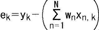


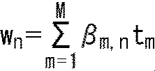


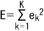


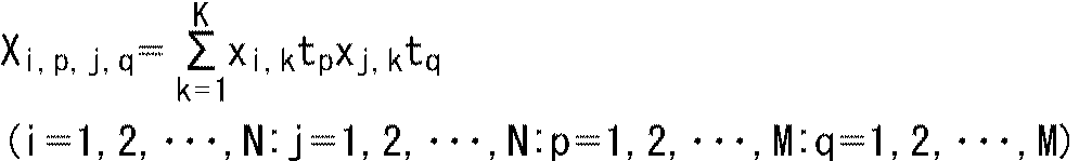
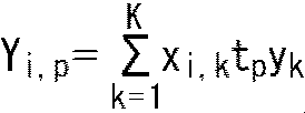


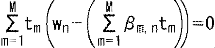
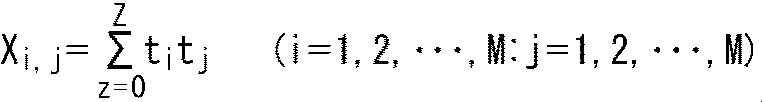
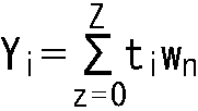
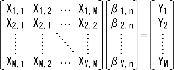
このような階層画像符号化・階層画像復号(スケーラブル符号化・スケーラブル復号)において、スケーラビリティ(scalability)機能を有するパラメータは、任意である。例えば、空間解像度をそのパラメータとしてもよい(spatial scalability)。このスペーシャルスケーラビリティ(spatial scalability)の場合、レイヤ毎に画像の解像度が異なる。
ビデオセット1300は、画像データを処理する各種装置に組み込むことができる。例えば、ビデオセット1300は、テレビジョン装置1200(図87)、携帯電話機1220(図88)、記録再生装置1240(図89)、撮像装置1260(図90)等に組み込むことができる。ビデオセット1300を組み込むことにより、その装置は、上述した符号化装置11や復号装置12と同様の効果を得ることができる。
なお、本明細書では、各種情報が、符号化データ(ビットストリーム)に多重化されて、符号化側から復号側へ伝送される例について説明したが、これら情報を伝送する手法はかかる例に限定されない。例えば、これら情報は、符号化データに多重化されることなく、符号化データと関連付けられた別個のデータとして伝送され又は記録されてもよい。ここで、「関連付ける」という用語は、例えば、符号化データに含まれる画像(スライス若しくはブロック等、画像の一部であってもよい)と当該画像に対応する情報とを復号時にリンクさせ得るようにすることを意味する。すなわち、この符号化データ(画像)に関連付けられた情報は、符号化データ(画像)とは別の伝送路上で伝送されるようにしてもよい。また、この符号化データ(画像)に関連付けられた情報は、符号化データ(画像)とは別の記録媒体(又は同一の記録媒体の別の記録エリア)に記録されるようにしてもよい。さらに、画像とその画像に対応する情報とが、例えば、複数フレーム、1フレーム、又はフレーム内の一部分等の任意の単位で互いに関連付けられるようにしてもよい。
予測符号化の残差と予測画像とを加算することにより得られる第1の画像にフィルタ処理を行い、前記予測画像の予測に用いられる第2の画像を生成するフィルタ処理部を備え、
前記フィルタ処理部は、
前記第1の画像のうちの処理対象である処理対象画素に対応する前記第2の画像の対応画素の画素値を求める予測演算に用いられる予測タップとなる画素を、前記第1の画像から選択する予測タップ選択部と、
前記処理対象画素を、複数のクラスのうちのいずれかのクラスにクラス分類するクラス分類部と、
前記第1の画像に相当する生徒画像と、前記第1の画像に対応する元画像に相当する教師画像とを用いた学習により求められた、前記複数のクラスごとの、前記予測演算に用いられるタップ係数のうちの、前記処理対象画素のクラスのタップ係数を取得するタップ係数取得部と、
前記処理対象画素のクラスのタップ係数と、前記処理対象画素の前記予測タップとを用いた前記予測演算を行うことにより、前記対応画素の画素値を求める演算部と
を有する
画像処理装置。
<2>
前記タップ係数を伝送する伝送部をさらに備える
<1>に記載の画像処理装置。
<3>
前記学習を行う学習部をさらに備える
<2>に記載の画像処理装置。
<4>
前記クラス分類部は、前記第1の画像から得られる画像特徴量、及び、前記処理対象画素の予測符号化に関する符号化情報のうちの一方、又は、両方を用いて、クラス分類を行う
<2>に記載の画像処理装置。
<5>
前記伝送部は、前記符号化情報を伝送する
<4>に記載の画像処理装置。
<6>
前記クラス分類部は、
前記第1の画像から得られる画像特徴量、及び、前記処理対象画素の予測符号化に関する符号化情報のうちの一方、又は、両方を用いて、前記処理対象画素を第1クラスにクラス分類し、
復号側で取得することができない所定の情報を用いて、前記処理対象画素を第2クラスにクラス分類し、
前記第1クラス及び前記第2クラスから、前記処理対象画素の最終的なクラスを生成し、
前記伝送部は、前記第2クラスを伝送する
<2>ないし<5>のいずれかに記載の画像処理装置。
<7>
前記クラス分類部は、前記処理対象画素の最終的なクラスを、前記処理対象画素の最終的なクラスのクラス数を縮退した縮退クラスに変換する変換テーブルに従って、前記最終的なクラスを縮退クラスに変換し、
前記タップ係数取得部は、前記処理対象画素の前記縮退クラスのタップ係数を取得し、
前記伝送部は、前記変換テーブルを伝送する
<6>に記載の画像処理装置。
<8>
前記クラス分類部は、
前記クラス分類に用いられるクラスタップとなる、前記第1の画像の画素の画素値と、所定のクラス分類係数とを用いた予測演算により、前記処理対象画素が属するサブクラスに関する情報を予測したサブクラス予測値を求め、
前記サブクラス予測値に応じて、前記処理対象画素をサブクラスに分類する
ことを繰り返すことで、前記処理対象画素をクラス分類し、
前記伝送部は、前記クラス分類係数を伝送する
<2>に記載の画像処理装置。
<9>
前記生徒画像を用いて、前記タップ係数を求めるタップ係数学習を行い、
前記タップ係数と、前記生徒画像から選択された前記予測タップとを用いた予測演算により、前記教師画像の画素の画素予測値を求め、
前記画素予測値と、前記教師画像の画素の画素値とを比較することにより、前記サブクラスに関する情報を生成し、
前記生徒画像を用いた、前記サブクラスに関する情報を求める予測演算の結果と、前記サブクラスに関する情報との統計的な誤差を最小にする前記クラス分類係数を求めるクラス分類係数学習を行い、
前記クラス分類係数学習により得られる前記クラス分類係数と、前記生徒画像とを用いた予測演算により、前記生徒画像の画素の前記サブクラス予測値を求め、
前記サブクラス予測値に応じて、前記生徒画像の画素を前記サブクラスに分類し、
前記サブクラスごとに、そのサブクラスの前記生徒画像の画素を用いて、前記タップ係数学習を行う
ことを1階層の学習として行う学習部をさらに備える
<8>に記載の画像処理装置。
<10>
前記学習部は、前記画素予測値のS/N(Signal to Noise ratio)に応じて、前記1階層の学習を繰り返す
<9>に記載の画像処理装置。
<11>
前記伝送部は、最後の前記1階層の学習で得られる前記タップ係数と、すべての前記1階層の学習で得られる前記クラス分類係数とを伝送する
<10>に記載の画像処理装置。
<12>
前記学習部は、伝送が可能な伝送可能伝送量に応じて、所定回数目の前記1階層の学習で得られる前記タップ係数と、前記所定回数目までの前記1階層の学習で得られる前記クラス分類係数とを、伝送対象の伝送対象係数に設定し、
前記伝送部は、前記伝送対象係数を伝送する
<10>に記載の画像処理装置。
<13>
前記タップ係数を受け取る受け取り部をさらに備える
<1>に記載の画像処理装置。
<14>
前記クラス分類部は、前記第1の画像から得られる画像特徴量、及び、前記処理対象画素の予測符号化に関する符号化情報のうちの一方、又は、両方を用いて、クラス分類を行う
<13>に記載の画像処理装置。
<15>
前記受け取り部は、前記符号化情報を受け取る
<14>に記載の画像処理装置。
<16>
前記受け取り部は、前記第1の画像から得られる画像特徴量、及び、前記処理対象画素の予測符号化に関する符号化情報のうちの一方、又は、両方を用いたクラス分類により得られる第1クラスと、復号側で取得することができない所定の情報を用いた前記クラス分類により得られる第2クラスとのうちの、前記第2クラスを受け取り、
前記クラス分類部は、
前記処理対象画素を前記第1クラスにクラス分類し、
前記第1クラス、及び、前記受け取り部により受け取られた前記第2クラスから、前記処理対象画素の最終的なクラスを生成する
<13>ないし<15>のいずれかに記載の画像処理装置。
<17>
前記受け取り部は、前記処理対象画素の最終的なクラスを、前記処理対象画素の最終的なクラスのクラス数を縮退した縮退クラスに変換する変換テーブルを受け取り、
前記クラス分類部は、前記処理対象画素の最終的なクラスを、前記変換テーブルに従って、前記縮退クラスに変換する
<16>に記載の画像処理装置。
<18>
前記伝送部は、
前記生徒画像を用いて、前記タップ係数を求めるタップ係数学習を行い、
前記タップ係数と、前記生徒画像から選択された前記予測タップとを用いた予測演算により、前記教師画像の画素の画素予測値を求め、
前記画素予測値と、前記教師画像の画素の画素値とを比較することにより、前記生徒画像の画素が属するサブクラスに関する情報を生成し、
前記生徒画像と学習により求められるクラス分類係数とを用いた、前記サブクラスに関する情報を求める予測演算の結果と、前記サブクラスに関する情報との統計的な誤差を最小にする前記クラス分類係数を求めるクラス分類係数学習を行い、
前記クラス分類係数学習により得られる前記クラス分類係数と、前記生徒画像とを用いた予測演算により、前記生徒画像の画素の前記サブクラスに関する情報を予測したサブクラス予測値を求め、
前記サブクラス予測値に応じて、前記生徒画像の画素を前記サブクラスに分類し、
前記サブクラスごとに、そのサブクラスの前記生徒画像の画素を用いて、前記タップ係数学習を行う
1階層の学習を繰り返す
ことにより得られる前記タップ係数及び前記クラス分類係数を受け取り、
前記クラス分類部は、
前記クラス分類に用いられるクラスタップとなる、前記第1の画像の画素の画素値と、前記クラス分類係数とを用いた予測演算により、前記処理対象画素が属するサブクラスに関する情報を予測したサブクラス予測値を求め、
前記サブクラス予測値に応じて、前記処理対象画素をサブクラスに分類する
ことを繰り返すことで、前記処理対象画素をクラス分類する
<13>に記載の画像処理装置。
<19>
前記フィルタ処理部は、ILF(In Loop Filter)を構成するDF(Deblocking Filter),SAO(Sample Adaptive Offset)、及び、ALF(Adaptive Loop Filter)のうちの1以上として機能する
<1>ないし<18>のいずれかに記載の画像処理装置。
<20>
予測符号化の残差と予測画像とを加算することにより得られる第1の画像にフィルタ処理を行い、前記予測画像の予測に用いられる第2の画像を生成するステップを含み、
前記フィルタ処理は、
前記第1の画像のうちの処理対象である処理対象画素に対応する前記第2の画像の対応画素の画素値を求める予測演算に用いられる予測タップとなる画素を、前記第1の画像から選択することと、
前記処理対象画素を、複数のクラスのうちのいずれかのクラスにクラス分類することと、
前記第1の画像に相当する生徒画像と、前記第1の画像に対応する元画像に相当する教師画像とを用いた学習により求められた、前記複数のクラスごとの、前記予測演算に用いられるタップ係数のうちの、前記処理対象画素のクラスのタップ係数を取得することと、
前記処理対象画素のクラスのタップ係数と、前記処理対象画素の前記予測タップとを用いた前記予測演算を行うことにより、前記対応画素の画素値を求めることと
を含む
画像処理方法。
Claims (20)
- 予測符号化の残差と予測画像とを加算することにより得られる第1の画像にフィルタ処理を行い、前記予測画像の予測に用いられる第2の画像を生成するフィルタ処理部を備え、
前記フィルタ処理部は、
前記第1の画像のうちの処理対象である処理対象画素に対応する前記第2の画像の対応画素の画素値を求める予測演算に用いられる予測タップとなる画素を、前記第1の画像から選択する予測タップ選択部と、
前記処理対象画素を、複数のクラスのうちのいずれかのクラスにクラス分類するクラス分類部と、
前記第1の画像に相当する生徒画像と、前記第1の画像に対応する元画像に相当する教師画像とを用いた学習により求められた、前記複数のクラスごとの、前記予測演算に用いられるタップ係数のうちの、前記処理対象画素のクラスのタップ係数を取得するタップ係数取得部と、
前記処理対象画素のクラスのタップ係数と、前記処理対象画素の前記予測タップとを用いた前記予測演算を行うことにより、前記対応画素の画素値を求める演算部と
を有する
画像処理装置。 - 前記タップ係数を伝送する伝送部をさらに備える
請求項1に記載の画像処理装置。 - 前記学習を行う学習部をさらに備える
請求項2に記載の画像処理装置。 - 前記クラス分類部は、前記第1の画像から得られる画像特徴量、及び、前記処理対象画素の予測符号化に関する符号化情報のうちの一方、又は、両方を用いて、クラス分類を行う
請求項2に記載の画像処理装置。 - 前記伝送部は、前記符号化情報を伝送する
請求項4に記載の画像処理装置。 - 前記クラス分類部は、
前記第1の画像から得られる画像特徴量、及び、前記処理対象画素の予測符号化に関する符号化情報のうちの一方、又は、両方を用いて、前記処理対象画素を第1クラスにクラス分類し、
復号側で取得することができない所定の情報を用いて、前記処理対象画素を第2クラスにクラス分類し、
前記第1クラス及び前記第2クラスから、前記処理対象画素の最終的なクラスを生成し、
前記伝送部は、前記第2クラスを伝送する
請求項2に記載の画像処理装置。 - 前記クラス分類部は、前記処理対象画素の最終的なクラスを、前記処理対象画素の最終的なクラスのクラス数を縮退した縮退クラスに変換する変換テーブルに従って、前記最終的なクラスを縮退クラスに変換し、
前記タップ係数取得部は、前記処理対象画素の前記縮退クラスのタップ係数を取得し、
前記伝送部は、前記変換テーブルを伝送する
請求項6に記載の画像処理装置。 - 前記クラス分類部は、
前記クラス分類に用いられるクラスタップとなる、前記第1の画像の画素の画素値と、所定のクラス分類係数とを用いた予測演算により、前記処理対象画素が属するサブクラスに関する情報を予測したサブクラス予測値を求め、
前記サブクラス予測値に応じて、前記処理対象画素をサブクラスに分類する
ことを繰り返すことで、前記処理対象画素をクラス分類し、
前記伝送部は、前記クラス分類係数を伝送する
請求項2に記載の画像処理装置。 - 前記生徒画像を用いて、前記タップ係数を求めるタップ係数学習を行い、
前記タップ係数と、前記生徒画像から選択された前記予測タップとを用いた予測演算により、前記教師画像の画素の画素予測値を求め、
前記画素予測値と、前記教師画像の画素の画素値とを比較することにより、前記サブクラスに関する情報を生成し、
前記生徒画像を用いた、前記サブクラスに関する情報を求める予測演算の結果と、前記サブクラスに関する情報との統計的な誤差を最小にする前記クラス分類係数を求めるクラス分類係数学習を行い、
前記クラス分類係数学習により得られる前記クラス分類係数と、前記生徒画像とを用いた予測演算により、前記生徒画像の画素の前記サブクラス予測値を求め、
前記サブクラス予測値に応じて、前記生徒画像の画素を前記サブクラスに分類し、
前記サブクラスごとに、そのサブクラスの前記生徒画像の画素を用いて、前記タップ係数学習を行う
ことを1階層の学習として行う学習部をさらに備える
請求項8に記載の画像処理装置。 - 前記学習部は、前記画素予測値のS/N(Signal to Noise ratio)に応じて、前記1階層の学習を繰り返す
請求項9に記載の画像処理装置。 - 前記伝送部は、最後の前記1階層の学習で得られる前記タップ係数と、すべての前記1階層の学習で得られる前記クラス分類係数とを伝送する
請求項10に記載の画像処理装置。 - 前記学習部は、伝送が可能な伝送可能伝送量に応じて、所定回数目の前記1階層の学習で得られる前記タップ係数と、前記所定回数目までの前記1階層の学習で得られる前記クラス分類係数とを、伝送対象の伝送対象係数に設定し、
前記伝送部は、前記伝送対象係数を伝送する
請求項10に記載の画像処理装置。 - 前記タップ係数を受け取る受け取り部をさらに備える
請求項1に記載の画像処理装置。 - 前記クラス分類部は、前記第1の画像から得られる画像特徴量、及び、前記処理対象画素の予測符号化に関する符号化情報のうちの一方、又は、両方を用いて、クラス分類を行う
請求項13に記載の画像処理装置。 - 前記受け取り部は、前記符号化情報を受け取る
請求項14に記載の画像処理装置。 - 前記受け取り部は、前記第1の画像から得られる画像特徴量、及び、前記処理対象画素の予測符号化に関する符号化情報のうちの一方、又は、両方を用いたクラス分類により得られる第1クラスと、復号側で取得することができない所定の情報を用いた前記クラス分類により得られる第2クラスとのうちの、前記第2クラスを受け取り、
前記クラス分類部は、
前記処理対象画素を前記第1クラスにクラス分類し、
前記第1クラス、及び、前記受け取り部により受け取られた前記第2クラスから、前記処理対象画素の最終的なクラスを生成する
請求項13に記載の画像処理装置。 - 前記受け取り部は、前記処理対象画素の最終的なクラスを、前記処理対象画素の最終的なクラスのクラス数を縮退した縮退クラスに変換する変換テーブルを受け取り、
前記クラス分類部は、前記処理対象画素の最終的なクラスを、前記変換テーブルに従って、前記縮退クラスに変換する
請求項16に記載の画像処理装置。 - 前記伝送部は、
前記生徒画像を用いて、前記タップ係数を求めるタップ係数学習を行い、
前記タップ係数と、前記生徒画像から選択された前記予測タップとを用いた予測演算により、前記教師画像の画素の画素予測値を求め、
前記画素予測値と、前記教師画像の画素の画素値とを比較することにより、前記生徒画像の画素が属するサブクラスに関する情報を生成し、
前記生徒画像と学習により求められるクラス分類係数とを用いた、前記サブクラスに関する情報を求める予測演算の結果と、前記サブクラスに関する情報との統計的な誤差を最小にする前記クラス分類係数を求めるクラス分類係数学習を行い、
前記クラス分類係数学習により得られる前記クラス分類係数と、前記生徒画像とを用いた予測演算により、前記生徒画像の画素の前記サブクラスに関する情報を予測したサブクラス予測値を求め、
前記サブクラス予測値に応じて、前記生徒画像の画素を前記サブクラスに分類し、
前記サブクラスごとに、そのサブクラスの前記生徒画像の画素を用いて、前記タップ係数学習を行う
1階層の学習を繰り返す
ことにより得られる前記タップ係数及び前記クラス分類係数を受け取り、
前記クラス分類部は、
前記クラス分類に用いられるクラスタップとなる、前記第1の画像の画素の画素値と、前記クラス分類係数とを用いた予測演算により、前記処理対象画素が属するサブクラスに関する情報を予測したサブクラス予測値を求め、
前記サブクラス予測値に応じて、前記処理対象画素をサブクラスに分類する
ことを繰り返すことで、前記処理対象画素をクラス分類する
請求項13に記載の画像処理装置。 - 前記フィルタ処理部は、ILF(In Loop Filter)を構成するDF(Deblocking Filter),SAO(Sample Adaptive Offset)、及び、ALF(Adaptive Loop Filter)のうちの1以上として機能する
請求項1に記載の画像処理装置。 - 予測符号化の残差と予測画像とを加算することにより得られる第1の画像にフィルタ処理を行い、前記予測画像の予測に用いられる第2の画像を生成するステップを含み、
前記フィルタ処理は、
前記第1の画像のうちの処理対象である処理対象画素に対応する前記第2の画像の対応画素の画素値を求める予測演算に用いられる予測タップとなる画素を、前記第1の画像から選択することと、
前記処理対象画素を、複数のクラスのうちのいずれかのクラスにクラス分類することと、
前記第1の画像に相当する生徒画像と、前記第1の画像に対応する元画像に相当する教師画像とを用いた学習により求められた、前記複数のクラスごとの、前記予測演算に用いられるタップ係数のうちの、前記処理対象画素のクラスのタップ係数を取得することと、
前記処理対象画素のクラスのタップ係数と、前記処理対象画素の前記予測タップとを用いた前記予測演算を行うことにより、前記対応画素の画素値を求めることと
を含む
画像処理方法。
Priority Applications (6)
| Application Number | Priority Date | Filing Date | Title |
|---|---|---|---|
| EP20157289.8A EP3684056A1 (en) | 2016-05-02 | 2017-04-18 | Image processing using filtering based on pixel classification |
| CN201780025492.1A CN109076217A (zh) | 2016-05-02 | 2017-04-18 | 图像处理装置和图像处理方法 |
| EP17792682.1A EP3454557A4 (en) | 2016-05-02 | 2017-04-18 | IMAGE PROCESSING DEVICE AND IMAGE PROCESSING METHOD |
| US16/090,743 US20190124327A1 (en) | 2016-05-02 | 2017-04-18 | Image processing apparatus and image processing method |
| JP2018515418A JPWO2017191749A1 (ja) | 2016-05-02 | 2017-04-18 | 画像処理装置及び画像処理方法 |
| KR1020187030029A KR20190003497A (ko) | 2016-05-02 | 2017-04-18 | 화상 처리 장치 및 화상 처리 방법 |
Applications Claiming Priority (2)
| Application Number | Priority Date | Filing Date | Title |
|---|---|---|---|
| JP2016-092650 | 2016-05-02 | ||
| JP2016092650 | 2016-05-02 |
Publications (1)
| Publication Number | Publication Date |
|---|---|
| WO2017191749A1 true WO2017191749A1 (ja) | 2017-11-09 |
Family
ID=60203107
Family Applications (1)
| Application Number | Title | Priority Date | Filing Date |
|---|---|---|---|
| PCT/JP2017/015521 Ceased WO2017191749A1 (ja) | 2016-05-02 | 2017-04-18 | 画像処理装置及び画像処理方法 |
Country Status (6)
| Country | Link |
|---|---|
| US (1) | US20190124327A1 (ja) |
| EP (2) | EP3684056A1 (ja) |
| JP (1) | JPWO2017191749A1 (ja) |
| KR (1) | KR20190003497A (ja) |
| CN (1) | CN109076217A (ja) |
| WO (1) | WO2017191749A1 (ja) |
Cited By (3)
| Publication number | Priority date | Publication date | Assignee | Title |
|---|---|---|---|---|
| WO2019111720A1 (ja) * | 2017-12-06 | 2019-06-13 | ソニー株式会社 | 符号化装置、符号化方法、復号装置、及び、復号方法 |
| WO2019131161A1 (ja) * | 2017-12-27 | 2019-07-04 | ソニー株式会社 | 符号化装置、符号化方法、復号装置、及び、復号方法 |
| JP2022511310A (ja) * | 2018-11-12 | 2022-01-31 | サムスン エレクトロニクス カンパニー リミテッド | ディスプレイ装置及びその制御方法 |
Families Citing this family (7)
| Publication number | Priority date | Publication date | Assignee | Title |
|---|---|---|---|---|
| CN116760977A (zh) * | 2015-08-20 | 2023-09-15 | 日本放送协会 | 图像编码装置、图像解码装置、和其程序 |
| JP6977719B2 (ja) * | 2016-05-02 | 2021-12-08 | ソニーグループ株式会社 | 符号化装置及び符号化方法、並びに、復号装置及び復号方法 |
| JPWO2019107182A1 (ja) * | 2017-12-01 | 2020-11-26 | ソニー株式会社 | 符号化装置、符号化方法、復号装置、及び、復号方法 |
| EP3998772A4 (en) | 2019-07-11 | 2023-06-07 | Samsung Electronics Co., Ltd. | VIDEO DECODING METHOD AND APPARATUS, AND VIDEO CODING METHOD AND APPARATUS |
| CN111461147B (zh) * | 2020-04-30 | 2023-05-23 | 柳州智视科技有限公司 | 一种基于图像特征的二进制编码组织算法 |
| WO2023082107A1 (zh) * | 2021-11-10 | 2023-05-19 | Oppo广东移动通信有限公司 | 解码方法、编码方法、解码器、编码器和编解码系统 |
| US12205609B1 (en) * | 2023-07-21 | 2025-01-21 | Krisp Technologies, Inc. | Generating parallel data for real-time speech form conversion |
Citations (9)
| Publication number | Priority date | Publication date | Assignee | Title |
|---|---|---|---|---|
| JPS5347862B2 (ja) | 1973-01-11 | 1978-12-23 | ||
| JPH09237345A (ja) * | 1996-02-29 | 1997-09-09 | Sony Corp | クラス分類適応処理における学習方法 |
| JP2003299096A (ja) * | 2002-03-29 | 2003-10-17 | Sony Corp | 情報信号処理装置、情報信号処理方法、画像信号処理装置および画像表示装置、それに使用される係数種データの生成装置および生成方法、係数データの生成装置および生成方法、並びに各方法を実行するためのプログラムおよびそのプログラムを記録したコンピュータ読み取り可能な媒体 |
| JP4240322B2 (ja) | 2005-10-03 | 2009-03-18 | ソニー株式会社 | 係数生成装置及び係数生成方法 |
| WO2010146771A1 (ja) * | 2009-06-19 | 2010-12-23 | 三菱電機株式会社 | 画像符号化装置、画像復号装置、画像符号化方法及び画像復号方法 |
| JP4770711B2 (ja) | 2006-11-15 | 2011-09-14 | ソニー株式会社 | 画像処理装置、画像処理方法、およびプログラム |
| JP2012235407A (ja) * | 2011-05-09 | 2012-11-29 | Sony Corp | 画像処理装置および画像処理方法 |
| JP5485983B2 (ja) | 2009-04-03 | 2014-05-07 | パナソニック株式会社 | 動画像符号化方法、動画像復号方法、動画像符号化装置および動画像復号装置 |
| JP2014523183A (ja) | 2011-06-28 | 2014-09-08 | サムスン エレクトロニクス カンパニー リミテッド | ピクセル分類によるオフセット調整を利用するビデオ符号化方法及びその装置、並びに該ビデオ復号化方法及びその装置 |
Family Cites Families (13)
| Publication number | Priority date | Publication date | Assignee | Title |
|---|---|---|---|---|
| US6912255B2 (en) * | 2002-05-30 | 2005-06-28 | Mobixell Netwoks Inc. | Bit rate control through selective modification of DCT coefficients |
| JP4158479B2 (ja) * | 2002-10-18 | 2008-10-01 | ソニー株式会社 | 画像信号の処理装置および処理方法、それに使用される係数データの生成装置および生成方法、並びに各方法を実行するためのプログラム |
| US8503530B2 (en) * | 2004-05-27 | 2013-08-06 | Zhourong Miao | Temporal classified filtering for video compression |
| WO2009047643A2 (en) * | 2007-04-23 | 2009-04-16 | Comagna Kft. | Mehtod and apparatus for image processing |
| US8204128B2 (en) * | 2007-08-01 | 2012-06-19 | Her Majesty The Queen In Right Of Canada, As Represented By The Minister Of Industry, Through The Communications Research Centre Canada | Learning filters for enhancing the quality of block coded still and video images |
| CN101616324B (zh) * | 2009-07-28 | 2011-06-08 | 谭洪舟 | 压缩编码图像的块效应去除装置 |
| US8259819B2 (en) * | 2009-12-10 | 2012-09-04 | Hong Kong Applied Science and Technology Research Institute Company Limited | Method and apparatus for improving video quality by utilizing a unified loop filter |
| CN102857749B (zh) * | 2011-07-01 | 2016-04-13 | 华为技术有限公司 | 一种视频图像的像素分类方法和装置 |
| JP5810700B2 (ja) * | 2011-07-19 | 2015-11-11 | ソニー株式会社 | 画像処理装置及び画像処理方法 |
| JP2013085113A (ja) * | 2011-10-07 | 2013-05-09 | Sony Corp | 画像処理装置および方法 |
| US9357235B2 (en) * | 2011-10-13 | 2016-05-31 | Qualcomm Incorporated | Sample adaptive offset merged with adaptive loop filter in video coding |
| US9661322B2 (en) * | 2012-09-24 | 2017-05-23 | Intel Corporation | Histogram segmentation based local adaptive filter for video encoding and decoding |
| US20150256827A1 (en) * | 2012-09-28 | 2015-09-10 | Mitsubishi Electric Corporation | Video encoding device, video decoding device, video encoding method, and video decoding method |
-
2017
- 2017-04-18 EP EP20157289.8A patent/EP3684056A1/en not_active Withdrawn
- 2017-04-18 WO PCT/JP2017/015521 patent/WO2017191749A1/ja not_active Ceased
- 2017-04-18 EP EP17792682.1A patent/EP3454557A4/en not_active Withdrawn
- 2017-04-18 KR KR1020187030029A patent/KR20190003497A/ko not_active Ceased
- 2017-04-18 CN CN201780025492.1A patent/CN109076217A/zh active Pending
- 2017-04-18 US US16/090,743 patent/US20190124327A1/en not_active Abandoned
- 2017-04-18 JP JP2018515418A patent/JPWO2017191749A1/ja active Pending
Patent Citations (9)
| Publication number | Priority date | Publication date | Assignee | Title |
|---|---|---|---|---|
| JPS5347862B2 (ja) | 1973-01-11 | 1978-12-23 | ||
| JPH09237345A (ja) * | 1996-02-29 | 1997-09-09 | Sony Corp | クラス分類適応処理における学習方法 |
| JP2003299096A (ja) * | 2002-03-29 | 2003-10-17 | Sony Corp | 情報信号処理装置、情報信号処理方法、画像信号処理装置および画像表示装置、それに使用される係数種データの生成装置および生成方法、係数データの生成装置および生成方法、並びに各方法を実行するためのプログラムおよびそのプログラムを記録したコンピュータ読み取り可能な媒体 |
| JP4240322B2 (ja) | 2005-10-03 | 2009-03-18 | ソニー株式会社 | 係数生成装置及び係数生成方法 |
| JP4770711B2 (ja) | 2006-11-15 | 2011-09-14 | ソニー株式会社 | 画像処理装置、画像処理方法、およびプログラム |
| JP5485983B2 (ja) | 2009-04-03 | 2014-05-07 | パナソニック株式会社 | 動画像符号化方法、動画像復号方法、動画像符号化装置および動画像復号装置 |
| WO2010146771A1 (ja) * | 2009-06-19 | 2010-12-23 | 三菱電機株式会社 | 画像符号化装置、画像復号装置、画像符号化方法及び画像復号方法 |
| JP2012235407A (ja) * | 2011-05-09 | 2012-11-29 | Sony Corp | 画像処理装置および画像処理方法 |
| JP2014523183A (ja) | 2011-06-28 | 2014-09-08 | サムスン エレクトロニクス カンパニー リミテッド | ピクセル分類によるオフセット調整を利用するビデオ符号化方法及びその装置、並びに該ビデオ復号化方法及びその装置 |
Non-Patent Citations (1)
| Title |
|---|
| See also references of EP3454557A4 |
Cited By (7)
| Publication number | Priority date | Publication date | Assignee | Title |
|---|---|---|---|---|
| WO2019111720A1 (ja) * | 2017-12-06 | 2019-06-13 | ソニー株式会社 | 符号化装置、符号化方法、復号装置、及び、復号方法 |
| WO2019131161A1 (ja) * | 2017-12-27 | 2019-07-04 | ソニー株式会社 | 符号化装置、符号化方法、復号装置、及び、復号方法 |
| JPWO2019131161A1 (ja) * | 2017-12-27 | 2020-12-17 | ソニー株式会社 | 符号化装置、符号化方法、復号装置、及び、復号方法 |
| JP2022511310A (ja) * | 2018-11-12 | 2022-01-31 | サムスン エレクトロニクス カンパニー リミテッド | ディスプレイ装置及びその制御方法 |
| JP7214845B2 (ja) | 2018-11-12 | 2023-01-30 | サムスン エレクトロニクス カンパニー リミテッド | ディスプレイ装置及びその制御方法 |
| US11968382B2 (en) | 2018-11-12 | 2024-04-23 | Samsung Electronics Co., Ltd. | Display apparatus and method of controlling the same |
| US12425625B2 (en) | 2018-11-12 | 2025-09-23 | Samsung Electronics Co., Ltd. | Display apparatus and method of controlling the same using artificial intelligence (AI) |
Also Published As
| Publication number | Publication date |
|---|---|
| EP3454557A1 (en) | 2019-03-13 |
| EP3684056A1 (en) | 2020-07-22 |
| EP3454557A4 (en) | 2019-03-13 |
| JPWO2017191749A1 (ja) | 2019-03-07 |
| KR20190003497A (ko) | 2019-01-09 |
| CN109076217A (zh) | 2018-12-21 |
| US20190124327A1 (en) | 2019-04-25 |
Similar Documents
| Publication | Publication Date | Title |
|---|---|---|
| JP6780761B2 (ja) | 画像符号化装置および方法 | |
| EP3457692B1 (en) | Image processing device and method | |
| JP6977719B2 (ja) | 符号化装置及び符号化方法、並びに、復号装置及び復号方法 | |
| WO2017191749A1 (ja) | 画像処理装置及び画像処理方法 | |
| JP6883219B2 (ja) | 符号化装置及び符号化方法、並びに、システム | |
| JP7047776B2 (ja) | 符号化装置及び符号化方法、並びに、復号装置及び復号方法 | |
| JP6824034B2 (ja) | 画像復号装置および方法 | |
| WO2019039283A1 (ja) | 画像処理装置及び画像処理方法 | |
| WO2018173873A1 (ja) | 符号化装置及び符号化方法、並びに、復号装置及び復号方法 | |
| US20210297687A1 (en) | Encoding apparatus, encoding method, decoding apparatus, and decoding method | |
| EP3515070B1 (en) | Encoding color component prediction mode when using intra block copy | |
| US11423578B2 (en) | Encoding device, encoding method, decoding device, and decoding method |
Legal Events
| Date | Code | Title | Description |
|---|---|---|---|
| WWE | Wipo information: entry into national phase |
Ref document number: 2018515418 Country of ref document: JP |
|
| ENP | Entry into the national phase |
Ref document number: 20187030029 Country of ref document: KR Kind code of ref document: A |
|
| NENP | Non-entry into the national phase |
Ref country code: DE |
|
| 121 | Ep: the epo has been informed by wipo that ep was designated in this application |
Ref document number: 17792682 Country of ref document: EP Kind code of ref document: A1 |
|
| ENP | Entry into the national phase |
Ref document number: 2017792682 Country of ref document: EP Effective date: 20181203 |