WO2017188423A1 - ユーザ端末及び無線通信方法 - Google Patents
ユーザ端末及び無線通信方法 Download PDFInfo
- Publication number
- WO2017188423A1 WO2017188423A1 PCT/JP2017/016875 JP2017016875W WO2017188423A1 WO 2017188423 A1 WO2017188423 A1 WO 2017188423A1 JP 2017016875 W JP2017016875 W JP 2017016875W WO 2017188423 A1 WO2017188423 A1 WO 2017188423A1
- Authority
- WO
- WIPO (PCT)
- Prior art keywords
- transmission
- user terminal
- signal
- subframe
- bandwidth
- Prior art date
Links
Images


Classifications
-
- H—ELECTRICITY
- H04—ELECTRIC COMMUNICATION TECHNIQUE
- H04W—WIRELESS COMMUNICATION NETWORKS
- H04W56/00—Synchronisation arrangements
- H04W56/001—Synchronization between nodes
- H04W56/0025—Synchronization between nodes synchronizing potentially movable access points
-
- H—ELECTRICITY
- H04—ELECTRIC COMMUNICATION TECHNIQUE
- H04L—TRANSMISSION OF DIGITAL INFORMATION, e.g. TELEGRAPHIC COMMUNICATION
- H04L5/00—Arrangements affording multiple use of the transmission path
- H04L5/003—Arrangements for allocating sub-channels of the transmission path
- H04L5/0048—Allocation of pilot signals, i.e. of signals known to the receiver
-
- H—ELECTRICITY
- H04—ELECTRIC COMMUNICATION TECHNIQUE
- H04W—WIRELESS COMMUNICATION NETWORKS
- H04W4/00—Services specially adapted for wireless communication networks; Facilities therefor
- H04W4/30—Services specially adapted for particular environments, situations or purposes
- H04W4/40—Services specially adapted for particular environments, situations or purposes for vehicles, e.g. vehicle-to-pedestrians [V2P]
-
- H—ELECTRICITY
- H04—ELECTRIC COMMUNICATION TECHNIQUE
- H04W—WIRELESS COMMUNICATION NETWORKS
- H04W4/00—Services specially adapted for wireless communication networks; Facilities therefor
- H04W4/70—Services for machine-to-machine communication [M2M] or machine type communication [MTC]
-
- H—ELECTRICITY
- H04—ELECTRIC COMMUNICATION TECHNIQUE
- H04W—WIRELESS COMMUNICATION NETWORKS
- H04W72/00—Local resource management
- H04W72/04—Wireless resource allocation
-
- H—ELECTRICITY
- H04—ELECTRIC COMMUNICATION TECHNIQUE
- H04W—WIRELESS COMMUNICATION NETWORKS
- H04W72/00—Local resource management
- H04W72/04—Wireless resource allocation
- H04W72/044—Wireless resource allocation based on the type of the allocated resource
- H04W72/0446—Resources in time domain, e.g. slots or frames
-
- H—ELECTRICITY
- H04—ELECTRIC COMMUNICATION TECHNIQUE
- H04W—WIRELESS COMMUNICATION NETWORKS
- H04W72/00—Local resource management
- H04W72/12—Wireless traffic scheduling
-
- H—ELECTRICITY
- H04—ELECTRIC COMMUNICATION TECHNIQUE
- H04W—WIRELESS COMMUNICATION NETWORKS
- H04W8/00—Network data management
-
- G—PHYSICS
- G01—MEASURING; TESTING
- G01S—RADIO DIRECTION-FINDING; RADIO NAVIGATION; DETERMINING DISTANCE OR VELOCITY BY USE OF RADIO WAVES; LOCATING OR PRESENCE-DETECTING BY USE OF THE REFLECTION OR RERADIATION OF RADIO WAVES; ANALOGOUS ARRANGEMENTS USING OTHER WAVES
- G01S19/00—Satellite radio beacon positioning systems; Determining position, velocity or attitude using signals transmitted by such systems
- G01S19/01—Satellite radio beacon positioning systems transmitting time-stamped messages, e.g. GPS [Global Positioning System], GLONASS [Global Orbiting Navigation Satellite System] or GALILEO
- G01S19/03—Cooperating elements; Interaction or communication between different cooperating elements or between cooperating elements and receivers
- G01S19/05—Cooperating elements; Interaction or communication between different cooperating elements or between cooperating elements and receivers providing aiding data
-
- H—ELECTRICITY
- H04—ELECTRIC COMMUNICATION TECHNIQUE
- H04W—WIRELESS COMMUNICATION NETWORKS
- H04W72/00—Local resource management
- H04W72/04—Wireless resource allocation
- H04W72/044—Wireless resource allocation based on the type of the allocated resource
- H04W72/0453—Resources in frequency domain, e.g. a carrier in FDMA
-
- H—ELECTRICITY
- H04—ELECTRIC COMMUNICATION TECHNIQUE
- H04W—WIRELESS COMMUNICATION NETWORKS
- H04W72/00—Local resource management
- H04W72/20—Control channels or signalling for resource management
- H04W72/23—Control channels or signalling for resource management in the downlink direction of a wireless link, i.e. towards a terminal
Definitions
- the present invention relates to a user terminal and a wireless communication method in a next generation mobile communication system.
- LTE Long Term Evolution
- Non-patent Document 1 LTE successor systems (for example, LTE-A (LTE-Advanced), FRA (Future Radio Access), 5G (5th generation mobile communication system), New- RAT (called Radio Access Technology) is also being studied.
- LTE-A LTE-Advanced
- FRA Full Radio Access
- 5G 5th generation mobile communication system
- New- RAT called Radio Access Technology
- TDD Time Division Duplex
- FDD Frequency Division Duplex
- E-UTRA Evolved Universal Terrestrial Radio Access
- E-UTRAN Evolved Universal Terrestrial Radio Access Network
- the traffic ratio between UL and DL is not always constant, but varies with time or place. For this reason, in a radio communication system using TDD, radio resources are effectively used by dynamically changing the UL / DL resource configuration in a certain cell (transmission point, radio base station) according to traffic fluctuations. Is desired.
- a wireless frame (also referred to as a Lean radio frame) that is highly scalable in the future and excellent in power saving is being studied.
- the transmission direction such as UL or DL can be dynamically changed instead of using a predetermined UL / DL configuration as in the existing LTE system.
- the structure also called Highly flexible dynamic TDD is being studied.
- the transmission direction may differ between the transmission points at a certain timing (for example, TTI).
- TTI timing
- a large interference occurs between UL / DL and the communication quality is deteriorated.
- a large guard band between frequency bands that is the system band of each transmission point.
- the system bandwidth used for UL and DL transmission is narrowed, and the frequency utilization efficiency may be greatly reduced.
- the present invention has been made in view of the above points, and even when UL / DL is dynamically controlled, a user terminal that can suppress interference and suppress a significant decrease in frequency utilization efficiency.
- One of the objects is to provide a wireless communication method.
- a user terminal controls communication by switching between UL transmission and DL transmission for each subframe and / or within a subframe based on a receiving unit that receives downlink control information and the downlink control information And the control unit performs the UL transmission using a frequency band narrower than a frequency bandwidth used for the DL transmission.
- 10A and 10B are diagrams illustrating an example of a self-contained TTI. It is a figure explaining UL transmission power control in the case of using self-contained TTI. It is a figure explaining UL transmission power control in the case of using self-contained TTI. It is a figure which shows an example of schematic structure of the radio
- FIG. 1 is a diagram illustrating an example of a configuration of a lean radio frame.
- the lean radio frame has a predetermined time length (for example, 5-40 ms).
- the lean radio frame is composed of a plurality of subframes, and each subframe has a predetermined time length (for example, 0.125 ms, 0.25 ms, 1 ms, etc.).
- the subframe in the lean radio frame can be configured to have a shorter time length than the subframe of the existing LTE system (LTE Rel. 8-12). As a result, transmission / reception can be performed in a shorter time compared to the existing LTE system.
- the subframe is also called a transmission time interval (TTI).
- TTI transmission time interval
- the subframe in the lean radio frame can be shorter than the subframe (1 ms) of the existing LTE system (LTE Rel. 8-12).
- the subframe in the ream radio frame may be referred to as a shortened TTI (short TTI), a shortened subframe, or the like.
- the subframe in the lean radio frame can have the same length (1 ms) as the subframe of the existing LTE system (LTE Rel. 8-12).
- the subframe in the lean radio frame may be referred to as an LTE subframe, a normal TTI (normal TTI), a long TTI (long TTI), or the like.
- a part of subframes can be configured in advance as a DL transmission subframe (DL subframe). Since the DL subframe is a subframe whose transmission direction is predetermined, it is also called a fixed subframe or a fixed DL subframe.
- the fixed DL subframe can be set at a predetermined cycle (for example, a cycle of 5 ms or more).
- FIG. 1 shows a case where a fixed DL subframe is provided at the head of a lean radio frame. Note that the configuration of the lean radio frame and the number and position of the fixed DL subframes in the lean radio frame are not limited to those illustrated in FIG. A plurality of fixed DL subframes may be set in the lean radio frame.
- the fixed DL subframes are mapped in a concentrated manner at a specific time in the lean radio frame (for example, a specific 2 ms interval in a 10 ms period). For example, the energy consumption of a base station or a user terminal that performs transmission and reception in a fixed DL subframe can be suppressed by increasing the period.
- by distributing and mapping fixed DL subframes in lean radio frames it is possible to shorten the period of fixed DL subframes, and to easily ensure the connection quality of user terminals moving at high speed, for example.
- the time base resource position and period of the fixed DL subframe may be selected by the radio base station from a plurality of predefined combinations, and the user terminal may estimate the possible combinations blindly. It may be notified from the station to the user terminal by a broadcast signal, RRC signaling, or the like.
- the transmission direction of subframes other than the fixed DL subframe can be dynamically changed. Since the transmission direction is dynamically changed, the subframe is also called a flexible subframe, a dynamically used subframe, a dynamic subframe, or the like. In addition, it is considered that the dynamic subframe can dynamically change the transmission direction such as UL or DL (also referred to as Highly flexible dynamic TDD).
- the transmission direction (or UL / DL configuration) of the dynamic subframe may be specified by a fixed DL subframe (Semi-dynamic assignment), or the downlink control information (DL control channel, L1) of each dynamic subframe / L2 control signal, L1 / L2 control channel, etc.) (Dynamic assignment). That is, the transmission direction of dynamic subframes may be changed in units of radio frames including a plurality of subframes, or may be changed in units of subframes.
- dynamically changing the transmission direction of subframes within a lean radio frame is not limited to dynamic changes in units of subframes, and is not limited to units of radio frames made up of a plurality of subframes. It may include semi-dynamic changes.
- FIG. 2 is a diagram illustrating an example of a fixed DL subframe and a dynamic subframe.
- a case is shown in which fixed DL subframes are set for each predetermined period, and a plurality of dynamic subframes are set between fixed DL subframes.
- the configurations of the fixed DL subframe and the dynamic subframe shown in FIG. 2 are merely examples, and are not limited to those shown in FIG.
- DL data for example, DL data, UL data, DL sounding reference signal (also referred to as CSI measurement reference signal, CSI-RS), UL sounding reference signal (also referred to as SRS), uplink control information (UCI: Uplink Control Information).
- CSI-RS CSI measurement reference signal
- SRS UL sounding reference signal
- UCI Uplink Control Information
- cell discovery detection
- synchronization for example, cell discovery (detection), synchronization, measurement (for example, RRM (Radio Resource Management) measurement including RSRP (Reference Signal Received Power) measurement), mobility control, initial access control, etc. It is set as the structure which performs at least one.
- RRM Radio Resource Management
- RSRP Reference Signal Received Power
- signal transmission and / or reception processing (scheduling) in the dynamic subframe and the fixed DL subframe may be performed using the downlink control channel of each subframe.
- DL transmission assignment DL assignment
- UL assignment uplink transmission assignment
- downlink control information or downlink control channel
- assignment that completes transmission / reception control may be performed within the dynamic subframe. This assignment is also referred to as self-contained assignment.
- a subframe in which self-contained assignment is performed may be referred to as a self-contained subframe.
- the self-contained subframe may be referred to as, for example, a self-contained TTI, a self-contained symbol set, or other names may be used.
- a user terminal may receive a DL signal based on downlink control information and transmit a feedback signal (for example, HARQ-ACK) of the DL signal. Further, the user terminal may transmit a UL signal and receive a feedback signal of the UL signal based on the downlink control information.
- a self-contained subframe for example, feedback with an ultra-low delay of 1 ms or less can be realized, so that the delay time can be reduced.
- the radio base station and the user terminal can control communication by switching the upper and lower links within the subframe (or TTI).
- FIG. 3 shows an example in which TDD is applied by three operators AC using adjacent bands.
- the present inventors pay attention to the fact that interference between uplink and downlink occurs when the uplink and downlink overlap in an operator (or cell) whose frequency band is adjacent. In such a case, UL transmission and DL transmission are performed. It was conceived that a guard band (GP) is selectively set large between operators (or cells). As a result, interference between the upper and lower links is reduced, and a decrease in frequency utilization efficiency is suppressed as compared with a case where the system bandwidth used for UL transmission and DL transmission is narrowed (see, for example, FIG. 4). it can.
- GP guard band
- each operator uses one (for example, uplink) in a system that uses a TDD scheme in which upper and lower links are flexibly switched and operated for each TTI or within a TTI. ) Is set narrower than the other (for example, downlink).
- the present embodiment is not limited to operators having different frequency bands to be used, and can be applied between cells having different frequency bands. Further, the present invention can be applied to a system that uses a communication method in which UL transmission and DL transmission may overlap at a certain timing.
- the uplink frequency bandwidth is set narrower than that of the downlink is shown, but the same applies to the case where the downlink frequency bandwidth is set narrower than that of the uplink. can do. Moreover, it is good also as a structure applied only to UL transmission of a predetermined sub-frame (or TTI).
- the subframe may be a subframe (1 ms) in the existing LTE, or may be a period shorter than 1 ms (for example, any one of 1-13 symbols). It may be a period longer than 1 ms.
- FIG. 5 shows an example in which the uplink frequency bandwidth is set narrower than the downlink in a TDD system that operates by flexibly switching the uplink and downlink for each adjacent operator (or cell). ing.
- FIG. 5 shows a case where operators AC having adjacent frequency bands perform asynchronous operation by applying dynamic TDD independently.
- the radio base station and the user terminal have a wide frequency bandwidth (bandwidth). Can communicate using a narrow guard band.
- DL transmission can be performed using a wide frequency bandwidth, as in a system that operates in synchronization with the UL / DL configuration.
- interference between the upper and lower links does not occur even when the guard band is narrow.
- the operator When DL transmission and UL transmission are performed between different operators in a certain TTI (or within the TTI), the operator (or cell) that performs DL transmission performs communication in a wide frequency band and performs UL transmission.
- the operator performs communication in a frequency band set narrower than DL.
- the guard band for DL transmission is designed assuming synchronous operation of an existing system, and the frequency bandwidth is narrowed only when UL transmission is performed. Set a wide guard band between. Thereby, even if it is a case where dynamic TDD is operated asynchronously between operators (or cells), interference between upper and lower links can be suppressed. Further, by setting the frequency bandwidth to be narrow only in one transmission direction (for example, UL transmission), it is possible to reduce a significant decrease in frequency utilization efficiency.
- FIG. 5 shows the case where the bandwidth of all UL transmissions is set to be narrow
- the present embodiment is not limited to this.
- a configuration may be adopted in which the UL bandwidth is narrowed only for a part of the frequency bands.
- the UL bandwidth may be set to be narrow only for a predetermined TTI in the same frequency band. For example, in each operator (or each cell), when a predetermined TTI is set as a UL-dedicated TTI, the UL transmission of the TTI has a wider bandwidth (for example, the same bandwidth as the DL transmission). (Width) may be used for communication.
- the frequency bandwidth set for DL transmission and UL transmission may be defined in advance by specification, or may be changed and set as appropriate for each operator (or cell) and / or for each user terminal.
- An example of a method for setting different frequency bandwidths (asymmetric bandwidths) for DL transmission and UL transmission when the frequency bandwidth set for DL transmission and UL transmission is changed as appropriate is shown below. Note that the method of setting different frequency bandwidths for DL transmission and UL transmission is not limited to the example shown below.
- ⁇ Asymmetric bandwidth setting method 1> As an example of an asymmetric bandwidth setting method, in carrier aggregation (CA) in which a plurality of component carriers (CC: Component Carrier) to which TDD is applied is set, the number of carriers (number of CCs) is set to a different number in the upper and lower links. be able to.
- CA carrier aggregation
- CC Component Carrier
- FIG. 6 shows a case where the number of CCs used for UL transmission is set to be smaller than that used for DL transmission in each operator (or cell).
- the number of CCs used for DL transmission is set to 5 and the number of CCs used for UL transmission is set to less than 5 (here, 3). Show.
- the radio base station and the user terminal control communication using asymmetric CC numbers in the uplink and downlink.
- the uplink bandwidth can be easily set narrower than the downlink by setting the number of CCs.
- ⁇ Asymmetric bandwidth setting method 2> As another example of the asymmetric bandwidth setting method, in carrier aggregation (CA) in which a plurality of component carriers (CC) to which TDD is applied is set, the bandwidth of each carrier (CC) is set to a different width between the upper and lower links. May be.
- FIG. 7 shows a case in which the CC bandwidth used for UL transmission is set narrower than the CC bandwidth used for DL transmission in each operator (or cell).
- operator A or cell A
- the number of CCs used for DL transmission and UL transmission is set to five
- the bandwidth of CC (at least 1 CC) used for UL transmission is used for DL transmission.
- the bandwidth is set to be narrower than the bandwidth.
- the radio base station and the user terminal can control communication using the same number of CCs in the uplink and downlink when performing communication by dynamically switching between DL transmission and UL transmission within each TTI or within the TTI. .
- the uplink bandwidth can be reduced even when the same CC number is set in the uplink and downlink. It can be set narrower.
- FIG. 8 illustrates a case where each operator (or cell) extends a part of a carrier (for example, CC) used for DL transmission.
- operator A or cell A
- the radio base station and the user terminal control the DL transmission by using the extension portion in the downlink carrier when performing communication by dynamically switching between the DL transmission and the UL transmission for each TTI or within the TTI. .
- FIG. 9 illustrates a case where a part of a carrier (for example, CC) used for UL transmission is reduced in each operator (or cell).
- operator A or cell A
- the radio base station and the user terminal perform communication by dynamically switching between DL transmission and UL transmission within each TTI or within the TTI, the UL base station and the user terminal use the UL carrier portion after reduction in the UL carrier. Control transmission.
- the radio base station can notify the user terminal of information related to the bandwidth used for UL transmission and / or DL transmission.
- the radio base station includes information on the UL and DL system bandwidth and / or center frequency in cell-specific information (for example, broadcast information and system information) and notifies the user terminal. Can do.
- Information related to the bandwidth used for UL transmission and / or DL transmission may be information specifying the bandwidth, or information regarding the number of CCs to be set.
- the radio base station notifies the user terminal of information on the UL and DL system bandwidth and / or center frequency as user-specific information (UE-specific) included in higher layer signaling (for example, RRC signaling). May be.
- the radio base station may notify the user terminal of only one of the UL system bandwidth and / or center frequency information and the DL system bandwidth and / or center frequency information, or both. Also good.
- the radio base station notifies the user terminal in advance of information (candidate bandwidths) related to a plurality of bandwidths used for UL transmission and / or DL transmission using upper layer signaling and the like, and uses downlink control information.
- a predetermined bandwidth may be designated.
- the center frequency may be different between DL transmission and UL transmission, unlike TDD of the existing system.
- the radio base station may separately notify the user terminal of information on the UL system bandwidth and / or center frequency and information on the DL system bandwidth and / or center frequency.
- the user terminal may report in advance information on the configurable UL and DL maximum system bandwidths as user capability information (UE-capability) to the network (wireless base station).
- Information on the maximum system bandwidth of UL and DL may be the number of CCs that the user terminal can support.
- the radio base station determines the bandwidth to be used for UL transmission and / or DL transmission based on the user capability information notified from each user terminal, and narrows the bandwidth of the upper and lower links (for example, UL). Communication can be controlled by setting.
- signal assignment also referred to as self-contained assignment or self-contained operation
- TTI to which the signal allocation is performed is also called a self-contained TTI (self-contained TTI), a self-contained subframe, a self-contained symbol set, or the like.
- FIG. 10 is a diagram illustrating an example of a self-contained TTI.
- a reference signal (RS) / downlink control (DL control) region to which a reference signal and / or downlink control signal is mapped, and a downlink data signal are mapped.
- a downlink data (DL data) area to be transmitted and a feedback area to which delivery confirmation information for the downlink data signal is mapped are provided.
- a guard period may be provided as a downlink / uplink switching time between the data area and the feedback area.
- a reference signal / downlink control area to which a reference signal and / or a downlink control signal is mapped an uplink data area to which an uplink data signal is mapped
- a feedback area to which the acknowledgment information for the uplink data signal is mapped is provided.
- a guard period may be provided as a downlink / uplink switching time between the reference signal / downlink control area and the data area and between the data area and the feedback area, respectively.
- feedback information for example, ACK / NACK
- the self-contained TTI shown in FIGS. 10A and 10B is used.
- the delay time due to the feedback delay can be shortened.
- uplink data is transmitted 4 TTIs after the TTI that received the downlink control signal, so that the delay time due to the allocation delay can be shortened by using the self-contained TTI shown in FIG. 10B.
- the wireless base station may dynamically notify the user terminal of information regarding the self-contained UL bandwidth.
- the radio base station transmits information on system bandwidth and / or center frequency used for UL transmission (for example, UL data and / or UL control information (for example, HARQ-ACK)) to a DL control channel transmitted by the same TTI.
- the user terminal can determine the UL transmission parameters based on the information included in the DL control channel, and the radio base station transmits a predetermined number of times before the TTI that performs UL transmission.
- the user terminal may be notified of information on the system bandwidth and / or the center frequency used for UL transmission using the downlink control information of TTI.
- the user terminal may control transmission power based on the bandwidth of the UL transmission in the self-contained UL transmission. For example, the user terminal applies a predetermined transmission power offset according to the UL transmission bandwidth (see FIG. 11).
- FIG. 11 shows a case where self-contained allocation (allocation of DL data and UL control information here) is performed in each of three bands (Narrow band, Wider band, and Very wide band).
- the user terminal can apply the transmission power offset so that the UL transmission power becomes high when the UL transmission bandwidth is not set narrow but is a wide band (for example, the same as the DL bandwidth). For example, the user terminal applies the transmission power offset so that the UL transmission power becomes high in the narrow band and the wide band in FIG. Thereby, even if the influence of the interference with UL transmission is large, UL transmission can be performed appropriately.
- the user terminal can apply no transmission power offset, apply a transmission power offset smaller than when the UL transmission bandwidth is wide, or apply a negative transmission power offset.
- the user terminal applies a transmission power offset smaller than that when the UL transmission bandwidth is wide in the Vary wide band in which the transmission bandwidth of the uplink control information is set to be narrow.
- the UL transmission power is controlled by applying a negative transmission power offset.
- the transmission power offset can be specified in advance in association with the UL transmission bandwidth.
- information regarding the transmission power offset may be included in downlink control information included in the same TTI (or a TTI transmitted a predetermined number before) and notified to the user terminal.
- UL transmission power can be set.
- FIG. 11 shows the case where DL data is transmitted in each band
- the present embodiment is not limited to this.
- UL transmission power control can be similarly applied when transmitting UL data whose transmission bandwidth is set narrower than that of DL.
- Wireless communication system Hereinafter, the configuration of a wireless communication system according to an embodiment of the present invention will be described. In this wireless communication system, communication is performed using any one or combination of the wireless communication methods according to the above aspects of the present invention.
- FIG. 13 is a diagram illustrating an example of a schematic configuration of a wireless communication system according to an embodiment of the present invention.
- carrier aggregation (CA) and / or dual connectivity (DC) in which a plurality of basic frequency blocks (component carriers) each having a system bandwidth (for example, 20 MHz) of the LTE system as one unit are applied. can do.
- DC dual connectivity
- the wireless communication system 1 includes LTE (Long Term Evolution), LTE-A (LTE-Advanced), LTE-B (LTE-Beyond), SUPER 3G, IMT-Advanced 4G (4th generation mobile communication system), 5G. (5th generation mobile communication system), FRA (Future Radio Access), New-RAT (Radio Access Technology), etc., or a system that realizes these.
- LTE Long Term Evolution
- LTE-A Long Term Evolution-Advanced
- LTE-B LTE-Beyond
- SUPER 3G IMT-Advanced 4G (4th generation mobile communication system)
- 5G. 5th generation mobile communication system
- FRA Full Radio Access
- New-RAT Radio Access Technology
- a radio communication system 1 shown in FIG. 13 includes a radio base station 11 that forms a macro cell C1 with relatively wide coverage, and a radio base station 12 (12a) that is arranged in the macro cell C1 and forms a small cell C2 that is narrower than the macro cell C1. -12c). Moreover, the user terminal 20 is arrange
- the user terminal 20 can be connected to both the radio base station 11 and the radio base station 12. It is assumed that the user terminal 20 uses the macro cell C1 and the small cell C2 simultaneously by CA or DC. Moreover, the user terminal 20 may apply CA or DC using a plurality of cells (CC) (for example, 5 or less CCs, 6 or more CCs).
- CC cells
- Communication between the user terminal 20 and the radio base station 11 can be performed using a carrier having a relatively low frequency band (for example, 2 GHz) and a narrow bandwidth (referred to as an existing carrier or a legacy carrier).
- a carrier having a relatively high frequency band for example, 3.5 GHz, 5 GHz, etc.
- the same carrier may be used.
- the configuration of the frequency band used by each radio base station is not limited to this.
- a wired connection for example, an optical fiber compliant with CPRI (Common Public Radio Interface), an X2 interface, etc.
- a wireless connection It can be set as the structure to do.
- the radio base station 11 and each radio base station 12 are connected to the higher station apparatus 30 and connected to the core network 40 via the higher station apparatus 30.
- the upper station device 30 includes, for example, an access gateway device, a radio network controller (RNC), a mobility management entity (MME), and the like, but is not limited thereto.
- RNC radio network controller
- MME mobility management entity
- Each radio base station 12 may be connected to the higher station apparatus 30 via the radio base station 11.
- the radio base station 11 is a radio base station having a relatively wide coverage, and may be called a macro base station, an aggregation node, an eNB (eNodeB), a transmission / reception point, or the like.
- the radio base station 12 is a radio base station having local coverage, and includes a small base station, a micro base station, a pico base station, a femto base station, a HeNB (Home eNodeB), an RRH (Remote Radio Head), and transmission / reception. It may be called a point.
- the radio base stations 11 and 12 are not distinguished, they are collectively referred to as a radio base station 10.
- Each user terminal 20 is a terminal that supports various communication schemes such as LTE and LTE-A, and may include not only a mobile communication terminal (mobile station) but also a fixed communication terminal (fixed station).
- orthogonal frequency division multiple access (OFDMA) is applied to the downlink, and single carrier-frequency division multiple access (SC-FDMA) is used for the uplink.
- SC-FDMA single carrier-frequency division multiple access
- OFDMA is a multi-carrier transmission scheme that performs communication by dividing a frequency band into a plurality of narrow frequency bands (subcarriers) and mapping data to each subcarrier.
- SC-FDMA is a single-carrier transmission scheme that reduces interference between terminals by dividing the system bandwidth into bands consisting of one or continuous resource blocks for each terminal and using a plurality of terminals with mutually different bands. is there.
- the uplink and downlink radio access schemes are not limited to these combinations, and other radio access schemes may be used.
- downlink channels include a downlink shared channel (PDSCH) shared by each user terminal 20, a broadcast channel (PBCH: Physical Broadcast Channel), a downlink L1 / L2 control channel, and the like. Used. User data, higher layer control information, SIB (System Information Block), etc. are transmitted by PDSCH. Also, MIB (Master Information Block) is transmitted by PBCH.
- PDSCH downlink shared channel
- PBCH Physical Broadcast Channel
- SIB System Information Block
- MIB Master Information Block
- Downlink L1 / L2 control channels include PDCCH (Physical Downlink Control Channel), EPDCCH (Enhanced Physical Downlink Control Channel), PCFICH (Physical Control Format Indicator Channel), PHICH (Physical Hybrid-ARQ Indicator Channel), and the like.
- Downlink control information (DCI: Downlink Control Information) including scheduling information of PDSCH and PUSCH is transmitted by PDCCH.
- the number of OFDM symbols used for PDCCH is transmitted by PCFICH.
- the PHICH transmits HARQ (Hybrid Automatic Repeat reQuest) acknowledgment information (for example, retransmission control information, HARQ-ACK, ACK / NACK, etc.) to the PUSCH.
- HARQ Hybrid Automatic Repeat reQuest
- EPDCCH is frequency-division multiplexed with PDSCH (downlink shared data channel), and is used for transmission of DCI and the like in the same manner as PDCCH.
- an uplink shared channel (PUSCH) shared by each user terminal 20, an uplink control channel (PUCCH: Physical Uplink Control Channel), a random access channel (PRACH: Physical Random Access Channel) is used.
- PUSCH uplink shared channel
- PUCCH Physical Uplink Control Channel
- PRACH Physical Random Access Channel
- User data and higher layer control information are transmitted by PUSCH.
- downlink radio quality information CQI: Channel Quality Indicator
- delivery confirmation information and the like are transmitted by PUCCH.
- a random access preamble for establishing connection with a cell is transmitted by the PRACH.
- a cell-specific reference signal CRS
- CSI-RS channel state information reference signal
- DMRS demodulation reference signal
- PRS Positioning Reference Signal
- a measurement reference signal SRS: Sounding Reference Signal
- a demodulation reference signal DMRS
- the DMRS may be referred to as a user terminal specific reference signal (UE-specific Reference Signal). Further, the transmitted reference signal is not limited to these.
- FIG. 14 is a diagram illustrating an example of the overall configuration of a radio base station according to an embodiment of the present invention.
- the radio base station 10 includes a plurality of transmission / reception antennas 101, an amplifier unit 102, a transmission / reception unit 103, a baseband signal processing unit 104, a call processing unit 105, and a transmission path interface 106.
- the transmission / reception antenna 101, the amplifier unit 102, and the transmission / reception unit 103 may each be configured to include one or more.
- User data transmitted from the radio base station 10 to the user terminal 20 via the downlink is input from the higher station apparatus 30 to the baseband signal processing unit 104 via the transmission path interface 106.
- PDCP Packet Data Convergence Protocol
- RLC Radio Link Control
- MAC Medium Access
- Retransmission control for example, HARQ transmission processing
- scheduling transmission format selection, channel coding, Inverse Fast Fourier Transform (IFFT) processing, precoding processing, and other transmission processing
- IFFT Inverse Fast Fourier Transform
- precoding processing precoding processing, and other transmission processing
- the downlink control signal is also subjected to transmission processing such as channel coding and inverse fast Fourier transform, and is transferred to the transmission / reception unit 103.
- the transmission / reception unit 103 converts the baseband signal output by precoding for each antenna from the baseband signal processing unit 104 to a radio frequency band and transmits the converted signal.
- the radio frequency signal frequency-converted by the transmission / reception unit 103 is amplified by the amplifier unit 102 and transmitted from the transmission / reception antenna 101.
- the transmission / reception unit 103 can be configured by a transmitter / receiver, a transmission / reception circuit, or a transmission / reception device which is described based on common recognition in the technical field according to the present invention.
- the transmission / reception part 103 may be comprised as an integral transmission / reception part, and may be comprised from a transmission part and a receiving part.
- the radio frequency signal received by the transmission / reception antenna 101 is amplified by the amplifier unit 102.
- the transmission / reception unit 103 receives the uplink signal amplified by the amplifier unit 102.
- the transmission / reception unit 103 converts the frequency of the received signal into a baseband signal and outputs it to the baseband signal processing unit 104.
- the baseband signal processing unit 104 performs Fast Fourier Transform (FFT) processing, Inverse Discrete Fourier Transform (IDFT) processing, and error correction on user data included in the input upstream signal. Decoding, MAC retransmission control reception processing, RLC layer and PDCP layer reception processing are performed and transferred to the upper station apparatus 30 via the transmission path interface 106.
- the call processing unit 105 performs call processing such as communication channel setting and release, state management of the radio base station 10, and radio resource management.
- the transmission path interface 106 transmits and receives signals to and from the higher station apparatus 30 via a predetermined interface.
- the transmission path interface 106 transmits / receives signals (backhaul signaling) to / from other radio base stations 10 via an interface between base stations (for example, an optical fiber compliant with CPRI (Common Public Radio Interface), X2 interface). May be.
- CPRI Common Public Radio Interface
- X2 interface May be.
- the transmission / reception unit 103 transmits a DL signal (for example, downlink control information, downlink data, etc.) to be transmitted to the user terminal.
- the transmission / reception unit 103 can transmit the downlink control information including information specifying either UL transmission (for example, UL data allocation) or DL transmission (for example, DL data allocation) to the user terminal.
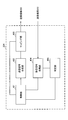
- FIG. 15 is a diagram illustrating an example of a functional configuration of a radio base station according to an embodiment of the present invention. Note that FIG. 15 mainly shows functional blocks of characteristic portions in the present embodiment, and the wireless base station 10 also has other functional blocks necessary for wireless communication. As illustrated in FIG. 15, the baseband signal processing unit 104 includes at least a control unit (scheduler) 301, a transmission signal generation unit 302, a mapping unit 303, a reception signal processing unit 304, and a measurement unit 305. ing.
- the baseband signal processing unit 104 includes at least a control unit (scheduler) 301, a transmission signal generation unit 302, a mapping unit 303, a reception signal processing unit 304, and a measurement unit 305. ing.
- the control unit (scheduler) 301 controls the entire radio base station 10.
- the control part 301 can be comprised from the controller, the control circuit, or control apparatus demonstrated based on the common recognition in the technical field which concerns on this invention.
- the control unit 301 controls signal generation by the transmission signal generation unit 302 and signal allocation by the mapping unit 303, for example.
- the control unit 301 also controls signal reception processing by the reception signal processing unit 304 and signal measurement by the measurement unit 305.
- the control unit 301 controls scheduling (for example, resource allocation) of system information, a downlink data signal transmitted on the PDSCH, and a downlink control signal transmitted on the PDCCH and / or EPDCCH. Further, the control unit 301 controls generation of a downlink control signal (for example, delivery confirmation information) and a downlink data signal based on a result of determining whether or not retransmission control is necessary for the uplink data signal.
- the control unit 301 also controls scheduling of synchronization signals (for example, PSS (Primary Synchronization Signal) / SSS (Secondary Synchronization Signal)) and downlink reference signals such as CRS, CSI-RS, and DMRS.
- the control unit 301 also includes an uplink data signal transmitted on the PUSCH, an uplink control signal (eg, delivery confirmation information) transmitted on the PUCCH and / or PUSCH, a random access preamble transmitted on the PRACH, an uplink reference signal, etc. Control the scheduling of
- the control unit 301 controls communication by dynamically switching between UL transmission and DL transmission for each subframe and / or within the subframe, and sets the frequency bandwidth used for one of the uplink and downlink (for example, UL transmission) to the other. Communication can be controlled by setting the frequency bandwidth narrower than (for example, DL transmission).
- the transmission signal generation unit 302 generates a downlink signal (downlink control signal, downlink data signal, downlink reference signal, etc.) based on an instruction from the control unit 301, and outputs it to the mapping unit 303.
- the transmission signal generation unit 302 can be configured by a signal generator, a signal generation circuit, or a signal generation device described based on common recognition in the technical field according to the present invention.
- the transmission signal generation unit 302 generates, for example, a DL assignment that notifies downlink signal allocation information and a UL grant that notifies uplink signal allocation information based on an instruction from the control unit 301.
- the downlink data signal is subjected to coding processing and modulation processing according to a coding rate, a modulation scheme, and the like determined based on channel state information (CSI: Channel State Information) from each user terminal 20.
- CSI Channel State Information
- the mapping unit 303 maps the downlink signal generated by the transmission signal generation unit 302 to a predetermined radio resource based on an instruction from the control unit 301, and outputs it to the transmission / reception unit 103.
- the mapping unit 303 can be configured by a mapper, a mapping circuit, or a mapping device described based on common recognition in the technical field according to the present invention.
- the reception signal processing unit 304 performs reception processing (for example, demapping, demodulation, decoding, etc.) on the reception signal input from the transmission / reception unit 103.
- the received signal is, for example, an uplink signal (uplink control signal, uplink data signal, uplink reference signal, etc.) transmitted from the user terminal 20.
- the reception signal processing unit 304 can be configured by a signal processor, a signal processing circuit, or a signal processing device described based on common recognition in the technical field according to the present invention.
- the reception signal processing unit 304 outputs the information decoded by the reception processing to the control unit 301. For example, when receiving PUCCH including HARQ-ACK, HARQ-ACK is output to control section 301.
- the reception signal processing unit 304 outputs the reception signal and the signal after reception processing to the measurement unit 305.
- the measurement unit 305 performs measurement on the received signal.
- the measurement part 305 can be comprised from the measuring device, measurement circuit, or measurement apparatus demonstrated based on common recognition in the technical field which concerns on this invention.
- the measurement unit 305 may measure, for example, received power (for example, RSRP (Reference Signal Received Power)), reception quality (for example, RSRQ (Reference Signal Received Quality)), channel state, and the like of the received signal.
- the measurement result may be output to the control unit 301.
- FIG. 16 is a diagram illustrating an example of the overall configuration of a user terminal according to an embodiment of the present invention.
- the user terminal 20 includes a plurality of transmission / reception antennas 201, an amplifier unit 202, a transmission / reception unit 203, a baseband signal processing unit 204, and an application unit 205.
- the transmission / reception antenna 201, the amplifier unit 202, and the transmission / reception unit 203 may each be configured to include one or more.
- the radio frequency signal received by the transmission / reception antenna 201 is amplified by the amplifier unit 202.
- the transmission / reception unit 203 receives the downlink signal amplified by the amplifier unit 202.
- the transmission / reception unit 203 converts the frequency of the received signal into a baseband signal and outputs it to the baseband signal processing unit 204.
- the transmission / reception unit 203 can be configured by a transmitter / receiver, a transmission / reception circuit, or a transmission / reception device described based on common recognition in the technical field according to the present invention.
- the transmission / reception unit 203 may be configured as an integral transmission / reception unit, or may be configured from a transmission unit and a reception unit.
- the baseband signal processing unit 204 performs FFT processing, error correction decoding, retransmission control reception processing, and the like on the input baseband signal.
- the downlink user data is transferred to the application unit 205.
- the application unit 205 performs processing related to layers higher than the physical layer and the MAC layer.
- broadcast information in the downlink data is also transferred to the application unit 205.
- uplink user data is input from the application unit 205 to the baseband signal processing unit 204.
- the baseband signal processing unit 204 performs transmission / reception by performing retransmission control transmission processing (for example, HARQ transmission processing), channel coding, precoding, discrete Fourier transform (DFT) processing, IFFT processing, and the like. Is transferred to the unit 203.
- the transmission / reception unit 203 converts the baseband signal output from the baseband signal processing unit 204 into a radio frequency band and transmits it.
- the radio frequency signal frequency-converted by the transmission / reception unit 203 is amplified by the amplifier unit 202 and transmitted from the transmission / reception antenna 201.
- the transmission / reception unit 203 receives a DL signal and transmits a UL signal.
- the transmission / reception unit 203 receives downlink control information transmitted from a radio base station.
- the transmission / reception unit 203 performs transmission / reception by dynamically switching between UL transmission and DL transmission for each subframe and / or within the subframe based on downlink control information, and transmits / receives data to one of the uplink and downlink (for example, DL reception).
- the other for example, UL transmission
- FIG. 17 is a diagram illustrating an example of a functional configuration of a user terminal according to an embodiment of the present invention. Note that FIG. 17 mainly shows functional blocks of characteristic portions in the present embodiment, and the user terminal 20 also has other functional blocks necessary for wireless communication. As illustrated in FIG. 17, the baseband signal processing unit 204 included in the user terminal 20 includes a control unit 401, a transmission signal generation unit 402, a mapping unit 403, a reception signal processing unit 404, and a determination unit 405. At least.
- the control unit 401 controls the entire user terminal 20.
- the control unit 401 can be composed of a controller, a control circuit, or a control device described based on common recognition in the technical field according to the present invention.
- the control unit 401 controls, for example, signal generation by the transmission signal generation unit 402 and signal allocation by the mapping unit 403.
- the control unit 401 controls signal reception processing by the reception signal processing unit 404 and signal measurement by the determination unit 405.
- the control unit 401 obtains, from the received signal processing unit 404, a downlink control signal (a signal transmitted by PDCCH / EPDCCH) and a downlink data signal (a signal transmitted by PDSCH) transmitted from the radio base station 10.
- the control unit 401 controls generation of an uplink control signal (for example, delivery confirmation information) and an uplink data signal based on a downlink control signal, a result of determining whether or not retransmission control is required for the downlink data signal, and the like.
- the control unit 401 controls communication by dynamically switching between UL transmission and DL transmission for each subframe and / or within a subframe based on downlink control information. For example, the control unit 401 performs control so as to perform the other (for example, UL transmission) using a frequency band narrower than the frequency bandwidth used for one of the upper and lower links (for example, DL transmission) (see FIG. 5).
- the control unit 401 performs control so as to perform the other (for example, UL transmission) using a frequency band narrower than the frequency bandwidth used for one of the upper and lower links (for example, DL transmission) (see FIG. 5).
- control unit 401 can perform UL transmission using a smaller number of CCs than the number of component carriers (CC) used for DL transmission (see FIG. 6). Or the control part 401 can perform UL transmission using CC by which the bandwidth narrower than the bandwidth of CC used for DL transmission is set (refer FIG. 7). Or the control part 401 can perform DL transmission using CC which expanded the bandwidth, and / or CC which reduced the bandwidth (refer FIG. 8, FIG. 9).
- CC component carriers
- control unit 401 controls UL transmission power by applying a predetermined power offset to CCs having different bandwidths between UL transmission and DL transmission. (See FIGS. 11 and 12).
- the transmission signal generation unit 402 generates an uplink signal (uplink control signal, uplink data signal, uplink reference signal, etc.) based on an instruction from the control unit 401 and outputs the uplink signal to the mapping unit 403.
- the transmission signal generation unit 402 can be configured by a signal generator, a signal generation circuit, or a signal generation device described based on common recognition in the technical field according to the present invention.
- the transmission signal generator 402 generates an uplink control signal related to delivery confirmation information and channel state information (CSI) based on an instruction from the controller 401, for example.
- the transmission signal generation unit 402 generates an uplink data signal based on an instruction from the control unit 401.
- the transmission signal generation unit 402 is instructed by the control unit 401 to generate an uplink data signal when the UL grant is included in the downlink control signal notified from the radio base station 10.
- the mapping unit 403 maps the uplink signal generated by the transmission signal generation unit 402 to a radio resource based on an instruction from the control unit 401, and outputs the radio signal to the transmission / reception unit 203.
- the mapping unit 403 can be configured by a mapper, a mapping circuit, or a mapping device described based on common recognition in the technical field according to the present invention.
- the reception signal processing unit 404 performs reception processing (for example, demapping, demodulation, decoding, etc.) on the DL signal (for example, downlink control signal transmitted from the radio base station, downlink data signal transmitted by PDSCH, etc.). I do.
- the reception signal processing unit 404 outputs information received from the radio base station 10 to the control unit 401 and the determination unit 405.
- the reception signal processing unit 404 outputs broadcast information, system information, RRC signaling, DCI, and the like to the control unit 401, for example.
- the reception signal processing unit 404 may be configured by a signal processor, a signal processing circuit or a signal processing device, and a measuring device, a measurement circuit or a measuring device which are described based on common recognition in the technical field according to the present invention. it can. Further, the reception signal processing unit 404 can constitute a reception unit according to the present invention.
- the determination unit 405 performs retransmission control determination (ACK / NACK) based on the decoding result of the received signal processing unit 404 and outputs the determination result to the control unit 401.
- ACK / NACK retransmission control determination
- ACK / NACK retransmission control determination
- the determination part 405 can be comprised from the determination circuit or determination apparatus demonstrated based on common recognition in the technical field which concerns on this invention.
- each functional block may be realized by one device physically and / or logically coupled, and two or more devices physically and / or logically separated may be directly and / or indirectly. (For example, wired and / or wireless) and may be realized by these plural devices.
- a radio base station, a user terminal, etc. in an embodiment of the present invention may function as a computer that performs processing of the radio communication method of the present invention.
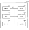
- FIG. 18 is a diagram illustrating an example of a hardware configuration of a radio base station and a user terminal according to an embodiment of the present invention.
- the wireless base station 10 and the user terminal 20 described above may be physically configured as a computer device including a processor 1001, a memory 1002, a storage 1003, a communication device 1004, an input device 1005, an output device 1006, a bus 1007, and the like. Good.
- the term “apparatus” can be read as a circuit, a device, a unit, or the like.
- the hardware configurations of the radio base station 10 and the user terminal 20 may be configured to include one or a plurality of each device illustrated in the figure, or may be configured not to include some devices.
- processor 1001 may be implemented by one or more chips.
- each function in the radio base station 10 and the user terminal 20 reads predetermined software (program) on hardware such as the processor 1001 and the memory 1002, so that the processor 1001 performs computation and communication by the communication device 1004.
- predetermined software program
- it is realized by controlling data reading and / or writing in the memory 1002 and the storage 1003.
- the processor 1001 controls the entire computer by operating an operating system, for example.
- the processor 1001 may be configured by a central processing unit (CPU) including an interface with peripheral devices, a control device, an arithmetic device, a register, and the like.
- CPU central processing unit
- the baseband signal processing unit 104 (204) and the call processing unit 105 described above may be realized by the processor 1001.
- the processor 1001 reads programs (program codes), software modules, data, and the like from the storage 1003 and / or the communication device 1004 to the memory 1002, and executes various processes according to these.
- programs program codes
- software modules software modules
- data data
- the like data
- the control unit 401 of the user terminal 20 may be realized by a control program stored in the memory 1002 and operated by the processor 1001, and may be realized similarly for other functional blocks.
- the memory 1002 is a computer-readable recording medium such as a ROM (Read Only Memory), an EPROM (Erasable Programmable ROM), an EEPROM (Electrically EPROM), a RAM (Random Access Memory), or any other suitable storage medium. It may be configured by one.
- the memory 1002 may be called a register, a cache, a main memory (main storage device), or the like.
- the memory 1002 can store programs (program codes), software modules, and the like that can be executed to implement the wireless communication method according to an embodiment of the present invention.
- the storage 1003 is a computer-readable recording medium such as a flexible disk, a floppy (registered trademark) disk, a magneto-optical disk (for example, a compact disk (CD-ROM (Compact Disc ROM)), a digital versatile disk, Blu-ray® disk), removable disk, hard disk drive, smart card, flash memory device (eg, card, stick, key drive), magnetic stripe, database, server, or other suitable storage medium It may be constituted by.
- the storage 1003 may be referred to as an auxiliary storage device.
- the communication device 1004 is hardware (transmission / reception device) for performing communication between computers via a wired and / or wireless network, and is also referred to as a network device, a network controller, a network card, a communication module, or the like.
- a network device for example, the transmission / reception antenna 101 (201), the amplifier unit 102 (202), the transmission / reception unit 103 (203), the transmission path interface 106, and the like described above may be realized by the communication device 1004.
- the input device 1005 is an input device (for example, a keyboard, a mouse, a microphone, a switch, a button, a sensor, etc.) that accepts an input from the outside.
- the output device 1006 is an output device (for example, a display, a speaker, an LED (Light Emitting Diode) lamp, etc.) that performs output to the outside.
- the input device 1005 and the output device 1006 may have an integrated configuration (for example, a touch panel).
- each device such as the processor 1001 and the memory 1002 is connected by a bus 1007 for communicating information.
- the bus 1007 may be configured with a single bus or may be configured with different buses between apparatuses.
- the radio base station 10 and the user terminal 20 include a microprocessor, a digital signal processor (DSP), an ASIC (Application Specific Integrated Circuit), a PLD (Programmable Logic Device), an FPGA (Field Programmable Gate Array), and the like. It may be configured including hardware, and a part or all of each functional block may be realized by the hardware. For example, the processor 1001 may be implemented by at least one of these hardware.
- DSP digital signal processor
- ASIC Application Specific Integrated Circuit
- PLD Programmable Logic Device
- FPGA Field Programmable Gate Array
- the channel and / or symbol may be a signal (signaling).
- the signal may be a message.
- the reference signal may be abbreviated as RS (Reference Signal), and may be referred to as a pilot, a pilot signal, or the like depending on an applied standard.
- a component carrier CC: Component Carrier
- CC Component Carrier
- the radio frame may be configured with one or a plurality of periods (frames) in the time domain.
- Each of the one or more periods (frames) constituting the radio frame may be referred to as a subframe.
- a subframe may be composed of one or more slots in the time domain.
- the slot may be configured with one or a plurality of symbols (OFDM (Orthogonal Frequency Division Multiplexing) symbol, SC-FDMA (Single Carrier Frequency Division Multiple Access) symbol, etc.) in the time domain).
- OFDM Orthogonal Frequency Division Multiplexing
- SC-FDMA Single Carrier Frequency Division Multiple Access
- the radio frame, subframe, slot, and symbol all represent a time unit when transmitting a signal.
- Different names may be used for the radio frame, the subframe, the slot, and the symbol.
- one subframe may be referred to as a transmission time interval (TTI)
- a plurality of consecutive subframes may be referred to as a TTI
- one slot may be referred to as a TTI.
- the subframe or TTI may be a subframe (1 ms) in the existing LTE, a period shorter than 1 ms (for example, 1-13 symbols), or a period longer than 1 ms. Also good.
- TTI means, for example, a minimum time unit for scheduling in wireless communication.
- a radio base station performs scheduling to allocate radio resources (frequency bandwidth, transmission power, etc. that can be used in each user terminal) to each user terminal in units of TTI.
- the definition of TTI is not limited to this.
- the TTI may be a transmission time unit of a channel-encoded data packet (transport block), or may be a processing unit such as scheduling or link adaptation.
- a TTI having a time length of 1 ms may be called a normal TTI (TTI in LTE Rel. 8-12), a normal TTI, a long TTI, a normal subframe, a normal subframe, or a long subframe.
- TTI shorter than a normal TTI may be called a shortened TTI, a short TTI, a shortened subframe, a short subframe, or the like.
- a resource block is a resource allocation unit in the time domain and the frequency domain, and may include one or a plurality of continuous subcarriers (subcarriers) in the frequency domain. Further, the RB may include one or a plurality of symbols in the time domain, and may have a length of one slot, one subframe, or 1 TTI. One TTI and one subframe may each be composed of one or a plurality of resource blocks.
- the RB may be called a physical resource block (PRB: Physical RB), a PRB pair, an RB pair, or the like.
- the resource block may be composed of one or a plurality of resource elements (RE: Resource Element).
- RE Resource Element
- 1RE may be a radio resource region of 1 subcarrier and 1 symbol.
- the structure of the above-described radio frame, subframe, slot, symbol, and the like is merely an example.
- the configuration such as the cyclic prefix (CP) length can be changed in various ways.
- information, parameters, and the like described in this specification may be represented by absolute values, may be represented by relative values from a predetermined value, or may be represented by other corresponding information.
- the radio resource may be indicated by a predetermined index.
- mathematical formulas and the like using these parameters may differ from those explicitly disclosed herein.
- PUCCH Physical Uplink Control Channel
- PDCCH Physical Downlink Control Channel
- information elements can be identified by any suitable name, so the various channels and information elements assigned to them.
- the name is not limiting in any way.
- information, signals, etc. can be output from the upper layer to the lower layer and / or from the lower layer to the upper layer.
- Information, signals, and the like may be input / output via a plurality of network nodes.
- the input / output information, signals, etc. may be stored in a specific location (for example, a memory), or may be managed by a management table. Input / output information, signals, and the like can be overwritten, updated, or added. The output information, signals, etc. may be deleted. Input information, signals, and the like may be transmitted to other devices.
- information notification includes physical layer signaling (eg, downlink control information (DCI), uplink control information (UCI)), upper layer signaling (eg, RRC (Radio Resource Control) signaling), It may be implemented by broadcast information (MIB (Master Information Block), SIB (System Information Block), etc.), MAC (Medium Access Control) signaling), other signals, or a combination thereof.
- DCI downlink control information
- UCI uplink control information
- RRC Radio Resource Control
- MIB Master Information Block
- SIB System Information Block
- MAC Medium Access Control
- the physical layer signaling may be referred to as L1 / L2 (Layer 1 / Layer 2) control information (L1 / L2 control signal), L1 control information (L1 control signal), or the like.
- the RRC signaling may be referred to as an RRC message, and may be, for example, an RRC connection setup (RRCConnectionSetup) message, an RRC connection reconfiguration (RRCConnectionReconfiguration) message, or the like.
- the MAC signaling may be notified by, for example, a MAC control element (MAC CE (Control Element)).
- notification of predetermined information is not limited to explicitly performed, but implicitly (for example, by not performing notification of the predetermined information or another (By notification of information).
- the determination may be performed by a value represented by 1 bit (0 or 1), or may be performed by a boolean value represented by true or false.
- the comparison may be performed by numerical comparison (for example, comparison with a predetermined value).
- software, instructions, information, etc. may be transmitted / received via a transmission medium.
- software can use websites, servers using wired technology (coaxial cable, fiber optic cable, twisted pair, digital subscriber line (DSL), etc.) and / or wireless technology (infrared, microwave, etc.) , Or other remote sources, these wired and / or wireless technologies are included within the definition of transmission media.
- system and “network” used in this specification are used interchangeably.
- base station BS
- radio base station eNB
- cell e.g., a fixed station
- eNodeB eNodeB
- cell group e.g., a cell
- carrier femtocell
- component carrier e.g., a fixed station, NodeB, eNodeB (eNB), access point, transmission point, reception point, femtocell, and small cell.
- the base station can accommodate one or a plurality of (for example, three) cells (also called sectors). If the base station accommodates multiple cells, the entire coverage area of the base station can be partitioned into multiple smaller areas, each smaller area being a base station subsystem (eg, an indoor small base station (RRH: The term “cell” or “sector” refers to part or all of the coverage area of a base station and / or base station subsystem that provides communication service in this coverage. Point to.
- RRH indoor small base station
- MS mobile station
- UE user equipment
- terminal may be used interchangeably.
- a base station may also be called in terms such as a fixed station, NodeB, eNodeB (eNB), access point, transmission point, reception point, femtocell, and small cell.
- NodeB NodeB
- eNodeB eNodeB
- access point transmission point
- reception point femtocell
- small cell small cell
- a mobile station is defined by those skilled in the art as a subscriber station, mobile unit, subscriber unit, wireless unit, remote unit, mobile device, wireless device, wireless communication device, remote device, mobile subscriber station, access terminal, mobile terminal, wireless It may also be called terminal, remote terminal, handset, user agent, mobile client, client or some other suitable terminology.
- the radio base station in this specification may be read by the user terminal.
- each aspect / embodiment of the present invention may be applied to a configuration in which communication between a radio base station and a user terminal is replaced with communication between a plurality of user terminals (D2D: Device-to-Device).
- the user terminal 20 may have a function that the wireless base station 10 has.
- words such as “up” and “down” may be read as “side”.
- the uplink channel may be read as a side channel.
- a user terminal in this specification may be read by a radio base station.
- the wireless base station 10 may have a function that the user terminal 20 has.
- the specific operation assumed to be performed by the base station may be performed by the upper node in some cases.
- various operations performed for communication with a terminal may be performed by one or more network nodes other than the base station and the base station (for example, It is obvious that this can be done by MME (Mobility Management Entity), S-GW (Serving-Gateway), etc., but not limited thereto) or a combination thereof.
- MME Mobility Management Entity
- S-GW Serving-Gateway
- each aspect / embodiment described in this specification may be used alone, in combination, or may be switched according to execution.
- the order of the processing procedures, sequences, flowcharts, and the like of each aspect / embodiment described in this specification may be changed as long as there is no contradiction.
- the methods described herein present the elements of the various steps in an exemplary order and are not limited to the specific order presented.
- Each aspect / embodiment described herein includes LTE (Long Term Evolution), LTE-A (LTE-Advanced), LTE-B (LTE-Beyond), SUPER 3G, IMT-Advanced, 4G (4th generation mobile). communication system), 5G (5th generation mobile communication system), FRA (Future Radio Access), New-RAT (Radio Access Technology), GSM (registered trademark) (Global System for Mobile communications), CDMA2000, UMB (Ultra Mobile Broadband) , IEEE 802.11 (Wi-Fi (registered trademark)), IEEE 802.16 (WiMAX (registered trademark)), IEEE 802.20, UWB (Ultra-WideBand), Bluetooth (registered trademark), and other appropriate wireless Systems utilizing communication methods and / or extensions based on them It may be applied to the next generation system.
- LTE Long Term Evolution
- LTE-A Long Term Evolution-Advanced
- LTE-B LTE-Beyond
- SUPER 3G IMT-Advanced
- the phrase “based on” does not mean “based only on”, unless expressly specified otherwise. In other words, the phrase “based on” means both “based only on” and “based at least on.”
- determining may encompass a wide variety of actions. For example, “determination” means calculating, computing, processing, deriving, investigating, looking up (eg, table, database or other data). It may be considered to “judge” (search in structure), ascertaining, etc.
- “determination (decision)” includes receiving (for example, receiving information), transmitting (for example, transmitting information), input (input), output (output), access ( accessing) (e.g., accessing data in memory), etc. may be considered to be “determining”. Also, “determination” is considered to be “determination (resolving)”, “selecting”, “choosing”, “establishing”, “comparing”, etc. Also good. That is, “determination (determination)” may be regarded as “determination (determination)” of some operation.
- the terms “connected”, “coupled”, or any variation thereof refers to any direct or indirect connection between two or more elements or By coupling, it can include the presence of one or more intermediate elements between two elements that are “connected” or “coupled” to each other.
- the coupling or connection between the elements may be physical, logical, or a combination thereof.
- the two elements are radio frequency by using one or more wires, cables and / or printed electrical connections, and as some non-limiting and non-inclusive examples
- electromagnetic energy such as electromagnetic energy having a wavelength in the region, microwave region, and light (both visible and invisible) region, it can be considered to be “connected” or “coupled” to each other.
Landscapes
- Engineering & Computer Science (AREA)
- Signal Processing (AREA)
- Computer Networks & Wireless Communication (AREA)
- Databases & Information Systems (AREA)
- Mobile Radio Communication Systems (AREA)
Priority Applications (5)
| Application Number | Priority Date | Filing Date | Title |
|---|---|---|---|
| US16/096,501 US20190116570A1 (en) | 2016-04-28 | 2017-04-28 | User terminal and radio communication method |
| CN201780026604.5A CN109076585B (zh) | 2016-04-28 | 2017-04-28 | 用户终端及无线通信方法 |
| JP2018514729A JP7078532B2 (ja) | 2016-04-28 | 2017-04-28 | 端末、無線通信方法、基地局及びシステム |
| EP17789704.8A EP3451777A4 (en) | 2016-04-28 | 2017-04-28 | USER TERMINAL AND METHOD FOR WIRELESS COMMUNICATION |
| IL262512A IL262512A (en) | 2016-04-28 | 2018-10-22 | User terminal and wireless communication method |
Applications Claiming Priority (2)
| Application Number | Priority Date | Filing Date | Title |
|---|---|---|---|
| JP2016091306 | 2016-04-28 | ||
| JP2016-091306 | 2016-04-28 |
Publications (1)
| Publication Number | Publication Date |
|---|---|
| WO2017188423A1 true WO2017188423A1 (ja) | 2017-11-02 |
Family
ID=60159781
Family Applications (1)
| Application Number | Title | Priority Date | Filing Date |
|---|---|---|---|
| PCT/JP2017/016875 WO2017188423A1 (ja) | 2016-04-28 | 2017-04-28 | ユーザ端末及び無線通信方法 |
Country Status (6)
| Country | Link |
|---|---|
| US (1) | US20190116570A1 (zh) |
| EP (1) | EP3451777A4 (zh) |
| JP (1) | JP7078532B2 (zh) |
| CN (1) | CN109076585B (zh) |
| IL (1) | IL262512A (zh) |
| WO (1) | WO2017188423A1 (zh) |
Cited By (1)
| Publication number | Priority date | Publication date | Assignee | Title |
|---|---|---|---|---|
| US11206705B2 (en) | 2018-07-23 | 2021-12-21 | At&T Mobility Ii Llc | Flexible carrier downlink and uplink pairing for advanced networks |
Families Citing this family (4)
| Publication number | Priority date | Publication date | Assignee | Title |
|---|---|---|---|---|
| KR102512852B1 (ko) * | 2017-09-08 | 2023-03-24 | 삼성전자 주식회사 | 무선 통신 시스템에서 상향링크 제어 신호를 전송하기 위한 장치 및 방법 |
| CN113424601A (zh) * | 2019-02-14 | 2021-09-21 | 株式会社Ntt都科摩 | 终端以及无线通信控制方法 |
| US11743923B1 (en) * | 2020-10-28 | 2023-08-29 | T-Mobile Innovations Llc | Dynamic radio resource provisioning based on network capability parameter |
| CN113079105B (zh) * | 2021-03-30 | 2023-03-24 | 联芸科技(杭州)股份有限公司 | 数据传输方法、系统、计算机设备和介质 |
Citations (3)
| Publication number | Priority date | Publication date | Assignee | Title |
|---|---|---|---|---|
| JP2014096847A (ja) * | 2008-12-26 | 2014-05-22 | Sharp Corp | 基地局装置、移動局装置、及び無線通信方法 |
| WO2015005463A1 (ja) * | 2013-07-12 | 2015-01-15 | シャープ株式会社 | 端末装置、方法および集積回路 |
| WO2015141770A1 (ja) * | 2014-03-20 | 2015-09-24 | シャープ株式会社 | 端末装置、基地局装置および方法 |
Family Cites Families (16)
| Publication number | Priority date | Publication date | Assignee | Title |
|---|---|---|---|---|
| US8290447B2 (en) * | 2007-01-19 | 2012-10-16 | Wi-Lan Inc. | Wireless transceiver with reduced transmit emissions |
| KR20100014091A (ko) * | 2008-08-01 | 2010-02-10 | 엘지전자 주식회사 | 다중 반송파 시스템에서 데이터 전송 방법 |
| CN101465720B (zh) * | 2009-01-23 | 2013-08-21 | 中兴通讯股份有限公司 | 一种发送上行harq反馈信息的方法和装置 |
| CN101540978B (zh) * | 2009-04-27 | 2013-09-11 | 中兴通讯股份有限公司 | 下行分量载波标识方法、同步下行分量载波上报方法与装置 |
| WO2013069218A1 (ja) * | 2011-11-07 | 2013-05-16 | パナソニック株式会社 | 端末装置、基地局装置、送信方法および受信方法 |
| EP2595425A1 (en) | 2011-11-18 | 2013-05-22 | Panasonic Corporation | Active bandwidth indicator for power-saving UEs |
| US9144065B2 (en) | 2011-12-16 | 2015-09-22 | Samsung Electronics Co., Ltd | Communication support for low capability devices |
| US9491741B2 (en) | 2012-05-02 | 2016-11-08 | Lg Electronics Inc. | Method for transmitting control information on low-cost machine-type communication, and apparatus for supporting same |
| US9622230B2 (en) * | 2012-05-17 | 2017-04-11 | Qualcomm Incorporated | Narrow band partitioning and efficient resource allocation for low cost user equipments |
| WO2014110815A1 (zh) * | 2013-01-18 | 2014-07-24 | 华为技术有限公司 | 公共控制信道的检测方法、传输方法及装置 |
| WO2015062051A1 (en) | 2013-10-31 | 2015-05-07 | Panasonic Intellectual Property Corporation Of America | Wireless communication method, enodeb, and user equipment |
| CN105850170B (zh) * | 2013-12-23 | 2019-06-11 | 华为技术有限公司 | 多载波聚合的方法、装置、用户设备及网络侧设备 |
| EP3089526B1 (en) * | 2013-12-27 | 2022-08-03 | Sharp Kabushiki Kaisha | Terminal device and method |
| JP2017079338A (ja) | 2014-02-28 | 2017-04-27 | シャープ株式会社 | 端末装置、基地局装置および方法 |
| US10560245B2 (en) * | 2014-10-21 | 2020-02-11 | Lg Electronics Inc. | Data transmission/reception method in wireless communication system that supports low latency, and apparatus therefor |
| CN106664702B (zh) * | 2015-08-12 | 2020-09-04 | 华为技术有限公司 | 一种数据传输方法、装置及系统 |
-
2017
- 2017-04-28 JP JP2018514729A patent/JP7078532B2/ja active Active
- 2017-04-28 CN CN201780026604.5A patent/CN109076585B/zh active Active
- 2017-04-28 US US16/096,501 patent/US20190116570A1/en active Pending
- 2017-04-28 WO PCT/JP2017/016875 patent/WO2017188423A1/ja active Application Filing
- 2017-04-28 EP EP17789704.8A patent/EP3451777A4/en not_active Withdrawn
-
2018
- 2018-10-22 IL IL262512A patent/IL262512A/en unknown
Patent Citations (3)
| Publication number | Priority date | Publication date | Assignee | Title |
|---|---|---|---|---|
| JP2014096847A (ja) * | 2008-12-26 | 2014-05-22 | Sharp Corp | 基地局装置、移動局装置、及び無線通信方法 |
| WO2015005463A1 (ja) * | 2013-07-12 | 2015-01-15 | シャープ株式会社 | 端末装置、方法および集積回路 |
| WO2015141770A1 (ja) * | 2014-03-20 | 2015-09-24 | シャープ株式会社 | 端末装置、基地局装置および方法 |
Non-Patent Citations (1)
| Title |
|---|
| See also references of EP3451777A4 * |
Cited By (1)
| Publication number | Priority date | Publication date | Assignee | Title |
|---|---|---|---|---|
| US11206705B2 (en) | 2018-07-23 | 2021-12-21 | At&T Mobility Ii Llc | Flexible carrier downlink and uplink pairing for advanced networks |
Also Published As
| Publication number | Publication date |
|---|---|
| CN109076585B (zh) | 2022-05-10 |
| JPWO2017188423A1 (ja) | 2019-03-07 |
| JP7078532B2 (ja) | 2022-05-31 |
| EP3451777A4 (en) | 2019-12-11 |
| CN109076585A (zh) | 2018-12-21 |
| IL262512A (en) | 2018-12-31 |
| US20190116570A1 (en) | 2019-04-18 |
| EP3451777A1 (en) | 2019-03-06 |
Similar Documents
| Publication | Publication Date | Title |
|---|---|---|
| JP6600014B2 (ja) | 端末及び無線通信方法 | |
| JP6721786B2 (ja) | 端末、無線通信方法及び基地局 | |
| JP6325597B2 (ja) | ユーザ端末、無線基地局及び無線通信方法 | |
| WO2017164147A1 (ja) | ユーザ端末、無線基地局及び無線通信方法 | |
| WO2018143393A1 (ja) | ユーザ端末及び無線通信方法 | |
| WO2018084138A1 (ja) | ユーザ端末及び無線通信方法 | |
| WO2018143399A1 (ja) | ユーザ端末及び無線通信方法 | |
| JP7078532B2 (ja) | 端末、無線通信方法、基地局及びシステム | |
| WO2017217456A1 (ja) | ユーザ端末及び無線通信方法 | |
| WO2018021203A1 (ja) | ユーザ端末及び無線通信方法 | |
| WO2017213222A1 (ja) | ユーザ端末および無線通信方法 | |
| WO2018198341A1 (ja) | ユーザ端末及び無線通信方法 | |
| WO2018203404A1 (ja) | ユーザ端末及び無線通信方法 | |
| WO2018079572A1 (ja) | ユーザ端末及び無線通信方法 | |
| WO2018084209A1 (ja) | ユーザ端末及び無線通信方法 | |
| WO2018030417A1 (ja) | ユーザ端末及び無線通信方法 | |
| CN110583062B (zh) | 用户终端以及无线通信方法 | |
| WO2018203399A1 (ja) | ユーザ端末及び無線通信方法 | |
| WO2018110619A1 (ja) | ユーザ端末及び無線通信方法 | |
| WO2018173234A1 (ja) | ユーザ端末及び無線通信方法 | |
| JP7467121B2 (ja) | 端末、基地局、無線通信方法及びシステム | |
| JPWO2017195850A1 (ja) | ユーザ端末及び無線通信方法 | |
| WO2018117207A1 (ja) | ユーザ端末及び無線通信方法 | |
| WO2018003646A1 (ja) | ユーザ端末及び無線通信方法 | |
| WO2017191809A1 (ja) | ユーザ端末及び無線通信方法 |
Legal Events
| Date | Code | Title | Description |
|---|---|---|---|
| ENP | Entry into the national phase |
Ref document number: 2018514729 Country of ref document: JP Kind code of ref document: A |
|
| NENP | Non-entry into the national phase |
Ref country code: DE |
|
| WWE | Wipo information: entry into national phase |
Ref document number: 2017789704 Country of ref document: EP |
|
| ENP | Entry into the national phase |
Ref document number: 2017789704 Country of ref document: EP Effective date: 20181128 |
|
| 121 | Ep: the epo has been informed by wipo that ep was designated in this application |
Ref document number: 17789704 Country of ref document: EP Kind code of ref document: A1 |