WO2018079572A1 - ユーザ端末及び無線通信方法 - Google Patents
ユーザ端末及び無線通信方法 Download PDFInfo
- Publication number
- WO2018079572A1 WO2018079572A1 PCT/JP2017/038419 JP2017038419W WO2018079572A1 WO 2018079572 A1 WO2018079572 A1 WO 2018079572A1 JP 2017038419 W JP2017038419 W JP 2017038419W WO 2018079572 A1 WO2018079572 A1 WO 2018079572A1
- Authority
- WO
- WIPO (PCT)
- Prior art keywords
- partial
- unit
- resource
- user terminal
- resource unit
- Prior art date
Links
Images


Classifications
-
- H—ELECTRICITY
- H04—ELECTRIC COMMUNICATION TECHNIQUE
- H04L—TRANSMISSION OF DIGITAL INFORMATION, e.g. TELEGRAPHIC COMMUNICATION
- H04L5/00—Arrangements affording multiple use of the transmission path
- H04L5/003—Arrangements for allocating sub-channels of the transmission path
- H04L5/0032—Distributed allocation, i.e. involving a plurality of allocating devices, each making partial allocation
- H04L5/0035—Resource allocation in a cooperative multipoint environment
-
- H—ELECTRICITY
- H04—ELECTRIC COMMUNICATION TECHNIQUE
- H04L—TRANSMISSION OF DIGITAL INFORMATION, e.g. TELEGRAPHIC COMMUNICATION
- H04L5/00—Arrangements affording multiple use of the transmission path
- H04L5/003—Arrangements for allocating sub-channels of the transmission path
- H04L5/0053—Allocation of signaling, i.e. of overhead other than pilot signals
-
- H—ELECTRICITY
- H04—ELECTRIC COMMUNICATION TECHNIQUE
- H04L—TRANSMISSION OF DIGITAL INFORMATION, e.g. TELEGRAPHIC COMMUNICATION
- H04L5/00—Arrangements affording multiple use of the transmission path
- H04L5/0001—Arrangements for dividing the transmission path
- H04L5/0003—Two-dimensional division
- H04L5/0005—Time-frequency
- H04L5/0007—Time-frequency the frequencies being orthogonal, e.g. OFDM(A), DMT
- H04L5/001—Time-frequency the frequencies being orthogonal, e.g. OFDM(A), DMT the frequencies being arranged in component carriers
-
- H—ELECTRICITY
- H04—ELECTRIC COMMUNICATION TECHNIQUE
- H04L—TRANSMISSION OF DIGITAL INFORMATION, e.g. TELEGRAPHIC COMMUNICATION
- H04L5/00—Arrangements affording multiple use of the transmission path
- H04L5/003—Arrangements for allocating sub-channels of the transmission path
- H04L5/0058—Allocation criteria
- H04L5/0064—Rate requirement of the data, e.g. scalable bandwidth, data priority
-
- H—ELECTRICITY
- H04—ELECTRIC COMMUNICATION TECHNIQUE
- H04L—TRANSMISSION OF DIGITAL INFORMATION, e.g. TELEGRAPHIC COMMUNICATION
- H04L5/00—Arrangements affording multiple use of the transmission path
- H04L5/0091—Signaling for the administration of the divided path
- H04L5/0092—Indication of how the channel is divided
-
- H—ELECTRICITY
- H04—ELECTRIC COMMUNICATION TECHNIQUE
- H04W—WIRELESS COMMUNICATION NETWORKS
- H04W72/00—Local resource management
- H04W72/04—Wireless resource allocation
-
- H—ELECTRICITY
- H04—ELECTRIC COMMUNICATION TECHNIQUE
- H04W—WIRELESS COMMUNICATION NETWORKS
- H04W72/00—Local resource management
- H04W72/04—Wireless resource allocation
- H04W72/044—Wireless resource allocation based on the type of the allocated resource
- H04W72/0453—Resources in frequency domain, e.g. a carrier in FDMA
-
- H—ELECTRICITY
- H04—ELECTRIC COMMUNICATION TECHNIQUE
- H04W—WIRELESS COMMUNICATION NETWORKS
- H04W72/00—Local resource management
- H04W72/12—Wireless traffic scheduling
- H04W72/1263—Mapping of traffic onto schedule, e.g. scheduled allocation or multiplexing of flows
-
- H—ELECTRICITY
- H04—ELECTRIC COMMUNICATION TECHNIQUE
- H04W—WIRELESS COMMUNICATION NETWORKS
- H04W72/00—Local resource management
- H04W72/50—Allocation or scheduling criteria for wireless resources
- H04W72/56—Allocation or scheduling criteria for wireless resources based on priority criteria
Definitions
- the present invention relates to a user terminal and a wireless communication method in a next generation mobile communication system.
- LTE Long Term Evolution
- LTE-A also referred to as LTE Advanced, LTE Rel. 10, 11 or 12
- LTE Long Term Evolution
- Successor systems for example, FRA (Future Radio Access), 5G (5th generation mobile communication system), 5G + (plus), NR (New Radio), NX (New radio access), New RAT (Radio Access Technology), FX ( Future generation radio access), LTE Rel.
- CA Carrier Aggregation
- CC Component Carrier
- eNB Radio Base Station
- BS Base Station
- UE User Equipment
- DC dual connectivity
- CG Cell Group
- CC cell
- Inter-eNB CA inter-base station CA
- LTE Rel. frequency division duplex (FDD) in which downlink (DL) transmission and uplink (UL: Uplink) transmission are performed in different frequency bands, and downlink transmission and uplink transmission are in the same frequency band.
- Time Division Duplex (TDD) which is performed by switching over time, is introduced.
- the UE and / or base station receives delivery confirmation information (also referred to as HARQ-ACK, ACK / NACK, etc.) regarding the transmitted data, and determines retransmission of data based on the information.
- delivery confirmation information also referred to as HARQ-ACK, ACK / NACK, etc.
- Future wireless communication systems for example, 5G, NR are expected to realize various wireless communication services to meet different requirements (for example, ultra-high speed, large capacity, ultra-low delay, etc.) Yes.
- eMBB enhanced Mobile Broad Band
- IoT Internet of Things
- mMTC massive Machine Type Communication
- M2M Machine To Machine
- URLLC Ultra Reliable and Low Latency Communications
- a radio resource unit called a resource block (RB).
- RB resource block
- 5G / NR a radio resource unit configured with a smaller number of subcarriers than the existing RB is being studied.
- specific settings of the partial RB, resource allocation, and the like have not been studied yet. For this reason, unless an appropriate method is defined, communication quality, throughput, and the like may deteriorate.
- the present invention has been made in view of such points, and even when a new control unit configured with a different number of subcarriers from an existing resource block is used, it is preferable to use the new control unit.
- An object is to provide a user terminal and a wireless communication method capable of communication.
- a user terminal includes: a receiving unit that receives information on a first resource unit including less than a predetermined number of subcarriers; and the same number of subcarriers as the predetermined number based on the information And a control unit for controlling a communication using the first resource unit in the frequency domain.
- 2A to 2C are diagrams illustrating an example of the configuration of the partial RB.
- 3A and 3B are diagrams showing another example of the configuration of the partial RB.
- 4A to 4E are diagrams illustrating an example of partial RB RS mapping in Embodiment 2.1. It is a figure which shows an example of the mapping of RS for partial RB in Embodiment 2.2. It is a figure which shows an example of the mapping of RS for partial RB in Embodiment 2.3.
- 7A to 7D are diagrams illustrating an example of a resource mapping pattern of data for the partial RB in the third embodiment.
- 8A and 8B are diagrams illustrating an example of resource mapping of downlink control channel candidates when using partial RBs according to the fifth embodiment.
- 9A to 9C are diagrams illustrating an example of uplink RS mapping in the seventh embodiment. It is a figure which shows an example of schematic structure of the radio
- RB radio resource unit
- the resource block may be called a subcarrier group (SCG), a resource element group (REG), a physical resource block (PRB), or the like.
- SCG subcarrier group
- REG resource element group
- PRB physical resource block
- a radio resource region configured with a frequency width of one subcarrier and a period of one OFDM symbol is called a resource element (RE).
- 5G / NR is required to support the use of flexible neurology and frequency and realize a dynamic frame configuration.
- the neurology is communication parameters related to the frequency domain and / or time domain (for example, subcarrier spacing (SCS), bandwidth, symbol length, cyclic prefix (CP) length, transmission). It means time interval (TTI: Transmission Time Interval) length, number of symbols per TTI, radio frame configuration, filtering process, windowing process, etc.).
- SCS subcarrier spacing
- CP cyclic prefix
- TTI Transmission Time Interval
- NR it is considered to support a plurality of neurology and apply different neurology to different services.
- a large SCS is used for URLLC to reduce delay
- a small SCS is used for mMTC to reduce power consumption.
- full RB may be called normal RB, etc.
- LTE SCS 15 kHz
- Control is being considered.
- partial RBs Fractional RBs
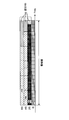
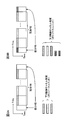
- FIG. 1 problems due to the difference in the size of the RB frequency resource depending on the value of SCS and the effect of partial RB introduction will be described.
- FIG. 1 is a diagram illustrating an example in which a partial RB is used.
- the UE is set with a system band having a predetermined width (for 23 RBs).
- the specific setting of the partial RB, the resource mapping method, etc. have not yet been studied. For this reason, unless an appropriate method is defined, the partial RB cannot be used suitably, and communication quality, throughput, and the like may deteriorate. Therefore, the present inventors have studied a technique for appropriately using the partial RB and found the present invention.
- the RB index to which the partial RB is assigned may be, for example, an index indicating an RB in a complete RB unit or an index indicating an RB in a partial RB unit.
- the UE can identify a complete RB based on the RB index and control communication using the partial RB within the frequency domain of the complete RB.
- the number of subcarriers included in the partial RB is a smaller value than the number of subcarriers of the normal RB (for example, 12), and may be 10, 8, 6, or 3, for example. However, when the RB is normally configured with a number of subcarriers greater than 12 in a predetermined numerology, the number of subcarriers included in the partial RB may be 12 or more.
- the relative position of the portion RB occupying the predetermined RB is, for example, left / right when the frequency is high / low (that is, as illustrated in FIG. 2 described later) in the RB including the portion RB. It may be expressed by a binary value such as whether it is right-justified or by an offset (number of subcarriers, etc.) from a frequency resource at which a predetermined RB starts. Note that the binary value may be represented by, for example, left / right. In this case, “left” may indicate a resource on the lower side of the frequency, or may indicate a resource on the higher side. Further, the offset may be a value that identifies a subcarrier having a resource allocation (non-empty) first in a predetermined RB (or a predetermined subband).
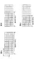
- FIG. 2 is a diagram illustrating an example of the configuration of the partial RB.
- FIG. 2A shows an example of complete RB, which is composed of 12 subcarriers ⁇ 7 symbols.
- 2B and 2C are examples of the partial RB, respectively, and are configured with 8 subcarriers and 6 subcarriers in the left side (low frequency side) region in the figure.
- the subcarriers constituting the partial RB are continuously arranged.
- FIG. 3 is a diagram illustrating another example of the configuration of the partial RB.
- FIG. 3A is an example of a partial RB of 10 subcarriers
- FIG. 3B is an example of a partial RB of 9 subcarriers.
- some of the subcarriers constituting the part RB are arranged in non-contiguous (comb-like) frequency resources.
- the predetermined subcarrier position is 8 subcarriers from the left side, and thereafter, the left subcarrier is used as a partial RB every 2 subcarriers.
- the predetermined subcarrier position is 6 subcarriers from the left side, and thereafter, the left subcarrier is used as a partial RB every 2 subcarriers.
- the subcarriers mapped in a comb shape may be right subcarriers every two subcarriers.
- the guard band can be reduced even when frequency division multiplexing (FDM) is performed between different neurology.
- FDM frequency division multiplexing
- the SCS of the neurology to be FDM is double (for example, 30 kHz) as compared to the SCS of the neurology using the partial RB (for example, 15 kHz) (for example, 30 kHz)
- both sides (high frequency side and low frequency side (left side and right side)) of the part RB may be discontinuous.
- all the subcarriers constituting part RB may be discontinuously arranged.
- every other RB may use 6 subcarriers.
- the predetermined subcarrier position is “none” or “zero subcarrier from the end”.
- the discontinuous subcarrier arrangement may be an arrangement other than using every other subcarrier, or an arrangement using every n (> 1) subcarriers.
- the parameter (information) related to the partial RB may be notified (set) to the UE semi-statically.
- the UE may assume (determine) that the RB is a partial RB.
- Semi-static notifications include upper layer signaling (for example, RRC (Radio Resource Control) signaling, broadcast information (master information block (MIB), system information block (SIB), etc.)), MAC ( Medium Access Control) signaling).
- RRC Radio Resource Control
- MIB master information block
- SIB system information block
- MAC Medium Access Control
- the parameter regarding the partial RB may be dynamically notified to the UE.
- the UE may assume (determine) that one or more RBs among the scheduled RBs are partial RBs based on the notified physical layer signaling (for example, downlink control information (DCI)). .
- DCI downlink control information
- the parameter regarding the partial RB may include information regarding whether or not the partial RB includes a non-contiguous subcarrier in the frequency direction.
- the parameter regarding the partial RB includes the predetermined subcarrier position (information for identifying subcarriers that are not guard bands) and / or non-continuous.
- Information on which side of the partial RB the subcarrier is used (eg, high and / or low, left and / or right) may be included.
- the parameter regarding the partial RB may be determined in association with the neurology, or may be determined based on another index.
- the UE may acquire a parameter related to the partial RB used in a predetermined carrier based on the set neurology and other indicators.
- Another indicator may be, for example, a carrier service type (eMBB, URLLC, etc.).
- the first embodiment can be applied to the setting of the partial RB regardless of the direction of the link (for example, in both downlink and uplink).
- the uplink setting will be further described in a sixth embodiment described later.
- the UE and / or the base station can determine the configuration of the partial RB to be used appropriately.
- the second embodiment relates to resource mapping of a reference signal (hereinafter also referred to as a partial RB RS) assigned to a partial RB area.
- the UE may use the RS for partial RB for reception processing (demodulation, decoding, etc.) of data and / or control signals transmitted by the partial RB, or measurement (for example, RRM (Radio Resource Management) measurement, CSI (Channel State Information) measurement).
- RRM Radio Resource Management
- CSI Channel State Information
- the partial RB RS is mapped using a resource mapping method (rule) different from the full RB RS. That is, in the partial RB, the RS may not be mapped to the resource to which the RS is mapped if it is a complete RB, and conversely, the RS may be mapped to a resource to which the RS is not mapped if it is a complete RB. Further, the partial RB RS may be mapped to a resource partially overlapping with the complete RB RS.
- the number of predetermined RSs allocated to partial RBs is preferably the same as the number of predetermined RSs allocated to complete RBs in order to maintain channel estimation accuracy, but may be different (for example, for complete RBs). (It may be increased or decreased based on the resource size (number of resource elements) of the partial RB).
- FIG. 4 is a diagram illustrating an example of mapping of RS for partial RB in the embodiment 2.1.
- FIG. 4A is a comparative example of complete RB, and shows resources to which four RSs of two antenna ports (antenna ports X and Y) are mapped.
- the RS is mapped to the head symbol of the complete RB, but the present invention is not limited to this.
- the number of RS antenna ports may be any number.
- FIG. 4B and 4C are diagrams illustrating an example of a front-loaded RS.
- the preceding arrangement RS is transmitted at an early stage (for example, the first symbol, the second symbol, etc.) of the partial RB.
- FIG. 4B is a partial RB of 8 subcarriers
- FIG. 4C is a partial RB of 6 subcarriers.
- the RS is transmitted with the first symbol as in the case of complete RBs.
- the number of RBs per port can be maintained.
- FIG. 4D and 4E are diagrams illustrating an example of a distributed RS.
- the distributed RS is transmitted using non-contiguous resources in the partial RB.
- FIG. 4D shows an 8-subcarrier partial RB
- FIG. 4E shows a 6-subcarrier partial RB. 4D and 4E, the number of RBs per port can be maintained.
- the partial RB RS may be mapped to the discontinuous frequency resource.
- the UE can perform transmission or reception processing by closing the partial RB.
- Embodiment 2.2 the partial RB RS is mapped to the same resource as the full RB RS. That is, in Embodiment 2.2, the resource (RE) of the partial RB RS is a subset of the resource (RE) of the complete RB RS.
- FIG. 5 is a diagram illustrating an example of mapping of RS for partial RB in the embodiment 2.2.
- the partial RB has frequency resources of 6 subcarriers, but is not limited thereto.
- the RE of the mapped signal (data, RS, control signal, etc.) if it was a complete RB is punctured or rate matched.
- the partial RB is scheduled adjacent to a full RB that is scheduled separately.
- the same precoding as that of the adjacent complete RB may be applied to the part RB.
- the UE can perform reception processing of data included in the partial RB using one or both RSs of the partial RB and the adjacent complete RB.
- Embodiment 2.2 when only the RS included in the partial RB is used, the channel estimation accuracy may be degraded. On the other hand, by using the adjacent complete RB RS, the channel estimation accuracy is degraded. Can be suppressed. Moreover, since UE maps RS according to the same rule about complete RB and partial RB, it can suppress the increase in processing load.
- Embodiment 2.3 the RS for partial RB is not defined. For this reason, in Embodiment 2.3, the partial RB does not include an RS resource (RE).
- RE RS resource
- FIG. 6 is a diagram illustrating an example of mapping of the partial RB RS in the embodiment 2.3. 6 is almost the same as FIG. 5, the difference will be mainly described below.
- the partial RB is scheduled adjacent to a separately scheduled full RB, and the same precoding as the complete RB is applied. preferable.
- the UE can perform reception processing of data included in the partial RB using the RS of the adjacent complete RB.
- a signal other than the RS such as a data signal and a control signal may be mapped to the resource to which the RS is mapped, or the signal may not be mapped (RE is null). And no transmission). Further, if the UE is a complete RB in the partial RB, the UE may ignore the resource to which the RS is mapped (the reception process may not be performed).
- the frequency use efficiency in the partial RB can be improved.
- the processing related to the partial RB can be appropriately performed using a predetermined reference signal.
- the third embodiment relates to data resource mapping rules in the partial RB.
- the data mapping method according to the third embodiment includes a first mapping method in the frequency direction (frequency-first and time-second mapping), a first mapping method in the time direction (time-first and frequency-second mapping), There is.
- the former may be called frequency priority mapping, and the latter may be called time priority mapping.
- the first data is mapped to the RE of the minimum subcarrier index and minimum symbol index of the area.
- Subsequent data is mapped in the direction in which the frequency increases, and when reaching the maximum frequency in the region, the data moves to the RE of the minimum subcarrier index of the next symbol index, and the same processing is performed. .
- the time priority mapping is equivalent to a method in which the frequency (subcarrier) and time (symbol) of the frequency priority mapping are exchanged.
- the subcarrier and / or symbol for starting mapping is not limited to the minimum one, and may be any RE included in a predetermined RB.
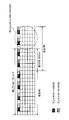
- FIG. 7 is a diagram illustrating an example of a resource mapping pattern of data for the partial RB in the third embodiment.
- FIG. 7 an example in which data is mapped to one or more complete RBs and two partial RBs adjacent to both ends of the complete RB (complete RBs and partial RBs are scheduled simultaneously (for overlapping time resources)) ), but the numbers and positions of the complete RBs and the partial RBs are not limited thereto.
- frequency priority mapping for example, the rules as shown in FIG. 7A or 7B may be followed. As shown in FIG. 7A, frequency priority mapping may be performed on data for all RBs allocated regardless of whether or not partial RBs are used. Further, as shown in FIG. 7B, after the data is subjected to frequency priority mapping by closing to the complete RB region, the subsequent data may be frequency priority mapped by closing to the partial RB region.
- time-priority mapping for example, a rule as shown in FIG. 7C or 7D may be followed.
- data may be time-prioritized for all RBs allocated regardless of whether or not partial RBs are used.
- FIG. 7D after the data is closed in the full RB area and time-prioritized mapping, the data is closed in the partial RB area and the subsequent data may be time-prioritized mapped.
- the data transmitted in the partial RB is located behind the soft buffer for retransmission / combination. Will be.
- the data behind the soft buffer may not be transmitted or synthesized (removed) during retransmission.
- the portion RB is located at the end of a predetermined band (for example, system band), and is assumed to be susceptible to interference (that is, reception quality is not good) from another adjacent neurology signal.
- mapping the data to the complete RB first, it is possible to store the data of the partial RB that is likely to cause an error behind the soft buffer. Thereby, reduction of HARQ performance of retransmission can be suppressed.
- rate matching can be easily applied even if, for example, at least one of the number and size of partial RBs varies during retransmission.
- data may be mapped to the partial RB in preference to the complete RB (first). That is, after the data is closed in the partial RB area and the data is subjected to frequency or time priority mapping, the data may be closed in the complete RB area and the subsequent data may be subjected to frequency or time priority mapping.
- the resource mapping pattern to be applied may be different from the case of initial transmission and / or another retransmission (hopping and / or switching may be performed). For example, even when the mapping for the first transmission is started from a predetermined RB (for example, the leftmost complete RB), the mapping at the time of retransmission is an RB that is shifted from the predetermined RB (for example, from the leftmost). It may start with the third full RB). By doing so, data at the time of retransmission is cyclically shifted in the frequency direction, and it is possible to suppress a situation in which only a part of data is mapped to the end of the band and continues to receive interference.
- a predetermined RB for example, the leftmost complete RB
- the mapping at the time of retransmission is an RB that is shifted from the predetermined RB (for example, from the leftmost). It may start with the third full RB).
- the UE and / or the base station may use chase combining for HARQ soft combining or IR (Incremental Redundancy).
- Chase combining is a method of transmitting the same parity bit as that used at the time of initial transmission when data is retransmitted.
- IR is a method of transmitting a parity bit different from the parity bit used at the time of initial transmission when data is retransmitted.
- the UE and / or the base station may perform the reception process assuming at least one mapping method described above. Moreover, UE and / or a base station may implement a reception process based on the mapping method specified according to the notified information.
- resource mapping of data can be performed appropriately.
- the fourth embodiment relates to a data modulation scheme and a coding rate (MCS) and a transport block size (TBS) in the partial RB.
- MCS coding rate
- TBS transport block size
- the UE and / or the base station calculates the TBS of the data based on the number of resources obtained by converting the resource of the scheduled partial RB into a complete RB unit. to decide.
- the TBS of the data including the partial RB may be obtained based on the converted complete RB number represented by the following formula 1.
- M complete RB number to be scheduled
- N is the part number of RB to be scheduled
- n x is the number of subcarriers included in the portion RB to be x-th schedule.
- the MCS of the data in the partial RB may be calculated based on at least one of the above-described TBS, the value of Equation 1, and M + N.
- the fifth embodiment relates to a downlink control channel when using partial RB.
- the downlink control channel can be assigned only to the complete RB (embodiment 5.1), or the downlink control channel can be assigned to both the complete RB and the partial RB (embodiment 5.2). .
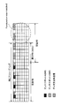
- FIG. 8 is a diagram illustrating an example of resource mapping of downlink control channel candidates when using partial RBs according to the fifth embodiment.
- FIG. 8 shows an example similar to FIG. 7, but the numbers and positions of complete RBs and partial RBs are not limited thereto.
- FIG. 8A corresponds to Embodiment 5.1.
- the downlink control channel candidate is not included in the partial RB. For this reason, the UE does not monitor downlink control channel candidates in the region belonging to the partial RB, and monitors downlink control channel candidates only in the region belonging to the complete RB.
- FIG. 8B corresponds to the embodiment 5.2.
- the downlink control channel candidate may be included in the partial RB. For this reason, the UE monitors downlink control channel candidates in the region belonging to the partial RB in addition to the region belonging to the complete RB.
- the partial RB may be regarded as a resource unit of the downlink control channel.
- the downlink control information can be appropriately acquired.
- the sixth embodiment relates to application of the partial RB to the uplink.
- the use of the partial RB may be limited only to the downlink (Embodiment 6.1). In this case, complications such as uplink power control and signal processing can be suppressed.
- the use of the partial RB may be limited to a predetermined access method for uplink (for example, cyclic prefix OFDM (CP-OFDM: Cyclic Prefix Orthogonal Frequency Division Multiplexing) ( Embodiment 6.2)
- CP-OFDM Cyclic Prefix Orthogonal Frequency Division Multiplexing
- DFT-S-OFDM Discrete Fourier Transform Spread Orthogonal Frequency Division Multiplexing
- the partial RB When the partial RB is used in the uplink, the partial RB may be used in a plurality of uplink access methods (for example, CP-OFDM and DFT-s-OFDM). There are cases where special control by partial RB is useful for DFT-s-OFDM.
- uplink access methods for example, CP-OFDM and DFT-s-OFDM.
- the usage mode of the partial RB in the uplink and the usage mode of the partial RB in the downlink may be different or the same.
- the UE may assume that the access schemes in which the partial RB can be used for the uplink and the downlink are different.
- uplink control can be appropriately performed even when a partial RB is set.
- the seventh embodiment relates to the RS of the partial RB in the uplink that is transmitted by a single carrier transmission scheme (eg, DFT-s-OFDM).
- a single carrier transmission scheme eg, DFT-s-OFDM
- DMRS Downlink demodulation Reference Signal
- CAZAC Constant Amplitude Zero Auto-Correlation
- the sequence length of the CAZAC sequence is defined as the maximum prime number that does not exceed 12, 24, or 12 ⁇ RB numbers.
- the DMRS base sequence in the existing LTE is a cyclic extension of a ZC (Zadoff-Chu) sequence determined by the maximum prime number not exceeding 12 ⁇ RB when the uplink transmission bandwidth is 3 RBs or more. (Cyclic extension) and is expressed as in Equation 2.
- M SC RS is the DMRS sequence length
- M SC RS mN SC RB .
- m is the number of RBs
- x q (m) is the q th ZC sequence
- N ZC RS is determined by the largest prime number that satisfies N ZC RS ⁇ M SC RS (e.g., the maximum number -1).
- Equation 2 and Equation 3 do not distinguish whether RB is a complete RB or a partial RB, it is assumed that it is not preferable to use it for an uplink RS sequence when the partial RB is set.
- the present inventors have found an uplink RS sequence when a partial RB is set for a single carrier transmission scheme (Embodiment 7.1-7.3).
- FIG. 9 illustrates an example in which the transmission bandwidth corresponds to a plurality of complete RBs and one partial RB, but is not limited thereto.
- Embodiment 7.1 a new CAZAC sequence shorter or longer than a CAZAC sequence (existing DMRS CAZAC sequence) used in the case of only complete RBs is defined.
- Sequence length N ZC RS of the sequence may be a value less than 12, such as 3,6,8,10, which may be defined by the largest prime number within the H SC of formula 4 ( In other words, it satisfies the N ZC RS ⁇ H SC).
- H SC corresponds to the total number of subcarriers for transmitting (valid signal).
- Embodiment 7.2 the cyclic extension of the CAZAC sequence (the existing DMRS CAZAC sequence) used in the case of only a complete RB is used for the RS of the partial RB.
- Sequence length N ZC RS of the sequence may be a value less than 12, such as 3,6,8,10, may be defined by the largest prime number within a predetermined value (M SC) .
- M SC 12M, which corresponds to the total number of subcarriers of only complete RB. That is, the sequence length of the CAZAC sequence in the embodiment 7.2 corresponds to the sequence length of the existing CAZAC sequence when only the complete RB is considered while ignoring the partial RB.
- Embodiment 7.3 As described in Embodiment 2.3, the RS for partial RB is not defined. That is, in Embodiment 7.3, RS is not mapped to the partial RB, and signals other than RS (data signal, control signal, etc.) are mapped. In this case, it is only necessary to map the RS to the complete RB, and there is no need to consider the RS of the partial RB.
- the UE may assume that the partial RB is scheduled adjacent to the full RB.
- the RS mapped to the full RB is generated from the CAZAC sequence as if only the full RB was scheduled.
- the CAZAC sequence may be a CAZAC sequence in the existing LTE.
- Sequence length N ZC RS of the sequence for example, may be defined by the largest prime number within the M SC described in the embodiment 7.2.
- a data signal and / or a control signal may be mapped to a resource to which an RS is mapped, or a signal may not be mapped. Further, if the UE is a complete RB in the partial RB, the UE may ignore the resource to which the RS is mapped (the reception process may not be performed).
- the eighth embodiment relates to power control of a partial RB in the uplink.
- the transmission power P PUSCH, c (i) of PUSCH (Physical Uplink Shared Channel) in the subframe i of the cell c can be expressed by Equation 5 below.
- P CMAX, c (i) is the maximum transmission power of the UE.
- M PUSCH, c (i) is the bandwidth (number of RBs) for PUSCH allocated to the UE.
- P 0_PUSCH, c (j) is a parameter (parameter related to transmission power offset) related to target received power (target received SNR: Signal to Noise Ratio).
- ⁇ c (j) is a weighting factor of fractional TPC.
- PL c corresponds to a path loss (propagation loss).
- ⁇ TF, c (i) is an offset based on MCS applied to PUSCH, and f c (i) is a correction value by a TPC command.
- P CMAX, c (i), M PUSCH, c (i), P 0_PUSCH, c (j), ⁇ c (j), PL c , ⁇ TF, c (i), f c (i) are , Respectively, may be expressed by omitting at least one of c, i, and j. Also, these values may be used for multiple cells and / or multiple subframes.
- Equation 5 does not distinguish whether RB is complete RB or partial RB, it is assumed that it is not preferable to use it for uplink power control when partial RB is set. Therefore, the present inventors have found uplink power control when the partial RB is set. Specifically, in the eighth embodiment, MPPUSCH of Formula 5 is newly defined as a bandwidth that appropriately considers the partial RB.
- the UE and / or the base station determines the PUSCH transmission power based on the number of resources obtained by converting the resource of the scheduled partial RB into a complete RB unit for the PUSCH including the partial RB.
- M PUSCH may be defined by Equation 6 below.
- M complete RB number to be scheduled
- N is the part number of RB to be scheduled
- n x is the number of subcarriers included in the portion RB to be x-th schedule.
- Equation 6 the bandwidth corresponding to the scheduled frequency resource is rounded up in units of RBs. Thereby, the same transmission power can be maintained regardless of whether the scheduled RB is a complete RB or a partial RB.
- M PUSCH may be defined by the following formula 7.
- Equation 7 the bandwidth corresponding to the scheduled frequency resource is not rounded up in units of RBs.
- PSD Power Spectrum Density
- an uplink control channel (PUCCH: Physical Uplink Shared Channel), an uplink reference signal (for example, SRS: Sounding Reference Signal), and the like can also control transmission power in consideration of the number of subcarriers included in the partial RB. it can.
- PUCCH Physical Uplink Shared Channel
- SRS Sounding Reference Signal
- ⁇ Modification> Information related to processing for the partial RB described in each embodiment may be defined in advance in the specification, upper layer signaling (for example, RRC signaling), physical layer signaling (for example, DCI), other signals, or these
- RRC signaling for example, RRC signaling
- DCI physical layer signaling
- the UE may be notified (set or instructed) by a combination.
- parameters related to the partial RB (region) first embodiment
- information related to the resource mapping pattern of the RS for partial RB second exemplary embodiment
- information for specifying the data mapping method third Embodiment
- information on resources of downlink control channel candidates for RS for partial RB fifth embodiment
- sequence length of CAZAC sequence used in partial RB seventh embodiment
- the UE may perform control on the partial RB and / or the complete RB based on the notified information.
- the partial RB having less than 12 subcarriers has been described.
- the present invention may be applied to RBs having other configurations.
- an RB having a number of subcarriers greater than 12 for example, may be referred to as a super RB
- the partial RB in each embodiment may be replaced with the super RB.
- the constant “12” in each embodiment may be another value.
- wireless communication system Wireless communication system
- communication is performed using any one or a combination of the wireless communication methods according to the above embodiments of the present invention.
- FIG. 10 is a diagram illustrating an example of a schematic configuration of a wireless communication system according to an embodiment of the present invention.
- carrier aggregation (CA) and / or dual connectivity (DC) in which a plurality of basic frequency blocks (component carriers) each having a system bandwidth (for example, 20 MHz) of the LTE system as one unit are applied. can do.
- DC dual connectivity
- the wireless communication system 1 includes LTE (Long Term Evolution), LTE-A (LTE-Advanced), LTE-B (LTE-Beyond), SUPER 3G, IMT-Advanced 4G (4th generation mobile communication system), 5G. (5th generation mobile communication system), FRA (Future Radio Access), New-RAT (Radio Access Technology), etc., or a system that realizes these.
- LTE Long Term Evolution
- LTE-A Long Term Evolution-Advanced
- LTE-B LTE-Beyond
- SUPER 3G IMT-Advanced 4G (4th generation mobile communication system)
- 5G. 5th generation mobile communication system
- FRA Full Radio Access
- New-RAT Radio Access Technology
- the radio communication system 1 includes a radio base station 11 that forms a macro cell C1 having a relatively wide coverage, and a radio base station 12 (12a-12c) that is arranged in the macro cell C1 and forms a small cell C2 that is narrower than the macro cell C1. It is equipped with. Moreover, the user terminal 20 is arrange
- the user terminal 20 can be connected to both the radio base station 11 and the radio base station 12. It is assumed that the user terminal 20 uses the macro cell C1 and the small cell C2 simultaneously by CA or DC. Moreover, the user terminal 20 may apply CA or DC using a plurality of cells (CC) (for example, 5 or less CCs, 6 or more CCs).
- CC cells
- Communication between the user terminal 20 and the radio base station 11 can be performed using a carrier having a relatively low frequency band (for example, 2 GHz) and a narrow bandwidth (also referred to as an existing carrier or a legacy carrier).
- a carrier having a relatively high frequency band for example, 3.5 GHz, 5 GHz, etc.
- the same carrier may be used.
- the configuration of the frequency band used by each radio base station is not limited to this.
- a wired connection for example, an optical fiber compliant with CPRI (Common Public Radio Interface), an X2 interface, etc.
- a wireless connection It can be set as the structure to do.
- the radio base station 11 and each radio base station 12 are connected to the higher station apparatus 30 and connected to the core network 40 via the higher station apparatus 30.
- the upper station device 30 includes, for example, an access gateway device, a radio network controller (RNC), a mobility management entity (MME), and the like, but is not limited thereto.
- RNC radio network controller
- MME mobility management entity
- Each radio base station 12 may be connected to the higher station apparatus 30 via the radio base station 11.
- the radio base station 11 is a radio base station having a relatively wide coverage, and may be called a macro base station, an aggregation node, an eNB (eNodeB), a transmission / reception point, or the like.
- the radio base station 12 is a radio base station having local coverage, and includes a small base station, a micro base station, a pico base station, a femto base station, a HeNB (Home eNodeB), an RRH (Remote Radio Head), and transmission / reception. It may be called a point.
- the radio base stations 11 and 12 are not distinguished, they are collectively referred to as a radio base station 10.
- Each user terminal 20 is a terminal that supports various communication schemes such as LTE and LTE-A, and may include not only a mobile communication terminal (mobile station) but also a fixed communication terminal (fixed station).
- orthogonal frequency division multiple access (OFDMA) is applied to the downlink, and single carrier-frequency division multiple access (SC-FDMA) is used for the uplink.
- SC-FDMA single carrier-frequency division multiple access
- OFDMA is a multi-carrier transmission scheme that performs communication by dividing a frequency band into a plurality of narrow frequency bands (subcarriers) and mapping data to each subcarrier.
- SC-FDMA is a single-carrier transmission scheme that reduces interference between terminals by dividing the system bandwidth into bands consisting of one or continuous resource blocks for each terminal and using a plurality of terminals with mutually different bands. is there.
- the uplink and downlink radio access schemes are not limited to these combinations, and other radio access schemes may be used.
- downlink channels include a downlink shared channel (PDSCH) shared by each user terminal 20, a broadcast channel (PBCH: Physical Broadcast Channel), a downlink L1 / L2 control channel, and the like. Used. User data, higher layer control information, SIB (System Information Block), etc. are transmitted by PDSCH. Also, MIB (Master Information Block) is transmitted by PBCH.
- PDSCH downlink shared channel
- PBCH Physical Broadcast Channel
- SIB System Information Block
- MIB Master Information Block
- Downlink L1 / L2 control channels include PDCCH (Physical Downlink Control Channel), EPDCCH (Enhanced Physical Downlink Control Channel), PCFICH (Physical Control Format Indicator Channel), PHICH (Physical Hybrid-ARQ Indicator Channel), and the like.
- Downlink control information (DCI: Downlink Control Information) including scheduling information of PDSCH and PUSCH is transmitted by PDCCH.
- the number of OFDM symbols used for PDCCH is transmitted by PCFICH.
- the PHICH transmits HARQ (Hybrid Automatic Repeat reQuest) acknowledgment information (for example, retransmission control information, HARQ-ACK, ACK / NACK, etc.) to the PUSCH.
- HARQ Hybrid Automatic Repeat reQuest
- EPDCCH is frequency-division multiplexed with PDSCH (downlink shared data channel), and is used for transmission of DCI and the like in the same manner as PDCCH.
- an uplink shared channel (PUSCH) shared by each user terminal 20
- an uplink control channel (PUCCH: Physical Uplink Control Channel)
- a random access channel (PRACH: Physical Random Access Channel)
- User data, higher layer control information, etc. are transmitted by PUSCH.
- downlink radio quality information (CQI: Channel Quality Indicator), delivery confirmation information, and the like are transmitted by PUCCH.
- CQI Channel Quality Indicator
- delivery confirmation information and the like are transmitted by PUCCH.
- a random access preamble for establishing connection with a cell is transmitted by the PRACH.
- a cell-specific reference signal CRS
- CSI-RS channel state information reference signal
- DMRS demodulation reference signal
- PRS Positioning Reference Signal
- a measurement reference signal SRS: Sounding Reference Signal
- a demodulation reference signal DMRS
- the DMRS may be referred to as a user terminal specific reference signal (UE-specific Reference Signal). Further, the transmitted reference signal is not limited to these.
- FIG. 11 is a diagram illustrating an example of the overall configuration of a radio base station according to an embodiment of the present invention.
- the radio base station 10 includes a plurality of transmission / reception antennas 101, an amplifier unit 102, a transmission / reception unit 103, a baseband signal processing unit 104, a call processing unit 105, and a transmission path interface 106.
- the transmission / reception antenna 101, the amplifier unit 102, and the transmission / reception unit 103 may each be configured to include one or more.
- User data transmitted from the radio base station 10 to the user terminal 20 via the downlink is input from the higher station apparatus 30 to the baseband signal processing unit 104 via the transmission path interface 106.
- PDCP Packet Data Convergence Protocol
- RLC Radio Link Control
- MAC Medium Access
- Retransmission control for example, HARQ transmission processing
- scheduling transmission format selection, channel coding, Inverse Fast Fourier Transform (IFFT) processing, precoding processing, and other transmission processing
- IFFT Inverse Fast Fourier Transform
- precoding processing precoding processing, and other transmission processing
- the downlink control signal is also subjected to transmission processing such as channel coding and inverse fast Fourier transform, and is transferred to the transmission / reception unit 103.
- the transmission / reception unit 103 converts the baseband signal output by precoding for each antenna from the baseband signal processing unit 104 to a radio frequency band and transmits the converted signal.
- the radio frequency signal frequency-converted by the transmission / reception unit 103 is amplified by the amplifier unit 102 and transmitted from the transmission / reception antenna 101.
- the transmission / reception unit 103 can be configured by a transmitter / receiver, a transmission / reception circuit, or a transmission / reception device which is described based on common recognition in the technical field according to the present invention.
- the transmission / reception part 103 may be comprised as an integral transmission / reception part, and may be comprised from a transmission part and a receiving part.
- the radio frequency signal received by the transmission / reception antenna 101 is amplified by the amplifier unit 102.
- the transmission / reception unit 103 receives the uplink signal amplified by the amplifier unit 102.
- the transmission / reception unit 103 converts the frequency of the received signal into a baseband signal and outputs it to the baseband signal processing unit 104.
- the baseband signal processing unit 104 performs Fast Fourier Transform (FFT) processing, Inverse Discrete Fourier Transform (IDFT) processing, and error correction on user data included in the input upstream signal. Decoding, MAC retransmission control reception processing, RLC layer and PDCP layer reception processing are performed and transferred to the upper station apparatus 30 via the transmission path interface 106.
- the call processor 105 performs communication channel call processing (setting, release, etc.), status management of the radio base station 10, radio resource management, and the like.
- the transmission path interface 106 transmits and receives signals to and from the higher station apparatus 30 via a predetermined interface.
- the transmission path interface 106 transmits / receives signals (backhaul signaling) to / from other radio base stations 10 via an interface between base stations (for example, an optical fiber compliant with CPRI (Common Public Radio Interface), X2 interface). May be.
- CPRI Common Public Radio Interface
- X2 interface May be.
- the transmission / reception unit 103 may transmit information on a partial RB (first resource unit) composed of subcarriers less than a predetermined number (for example, 12).
- the transmission / reception unit 103 may transmit and / or receive a signal assigned to the partial RB.
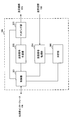
- FIG. 12 is a diagram illustrating an example of a functional configuration of a radio base station according to an embodiment of the present invention.
- the functional block of the characteristic part in this embodiment is mainly shown, and the wireless base station 10 shall also have another functional block required for radio
- the baseband signal processing unit 104 includes at least a control unit (scheduler) 301, a transmission signal generation unit 302, a mapping unit 303, a reception signal processing unit 304, and a measurement unit 305. These configurations may be included in the radio base station 10, and a part or all of the configurations may not be included in the baseband signal processing unit 104.
- the control unit (scheduler) 301 controls the entire radio base station 10.
- the control part 301 can be comprised from the controller, the control circuit, or control apparatus demonstrated based on the common recognition in the technical field which concerns on this invention.
- the control unit 301 controls, for example, signal generation by the transmission signal generation unit 302, signal allocation by the mapping unit 303, and the like.
- the control unit 301 also controls signal reception processing by the reception signal processing unit 304, signal measurement by the measurement unit 305, and the like.
- the control unit 301 controls scheduling (for example, resource allocation) of system information, downlink data signals (for example, signals transmitted by PDSCH), and downlink control signals (for example, signals transmitted by PDCCH and / or EPDCCH). . Further, the control unit 301 controls generation of a downlink control signal (for example, delivery confirmation information), a downlink data signal, and the like based on a result of determining whether or not retransmission control is required for the uplink data signal. Further, the control unit 301 controls scheduling of synchronization signals (for example, PSS (Primary Synchronization Signal) / SSS (Secondary Synchronization Signal)), downlink reference signals (for example, CRS, CSI-RS, DMRS) and the like.
- PSS Primary Synchronization Signal
- SSS Secondary Synchronization Signal
- the control unit 301 also includes an uplink data signal (for example, a signal transmitted on PUSCH), an uplink control signal (for example, a signal transmitted on PUCCH and / or PUSCH), a random access preamble transmitted on PRACH, and an uplink reference. Controls scheduling such as signals.
- the control unit 301 may perform scheduling using a partial RB (first resource unit) including subcarriers less than a predetermined number (for example, 12). Moreover, the control part 301 may perform control which transmits the information regarding partial RB to the user terminal 20.
- FIG. The control unit 301 may specify a frequency region of a complete RB (second resource unit) including the same number of subcarriers as the predetermined number, and may control communication using the partial RB within the frequency region. .
- the control unit 301 may perform control to map the reference signal used in the partial RB according to a resource mapping rule different from the resource mapping rule for the reference signal used in the complete RB.
- the control unit 301 may map the data to the resource of the complete RB in preference to the resource of the partial RB.
- control unit 301 may determine the transport block size and / or transmission power of the data based on the number of resources obtained by converting the resource of the scheduled partial RB into a complete RB. Good.
- the control unit 301 may perform control so that the downlink control channel is not transmitted in the region belonging to the partial RB.
- the control unit 301 may perform control assuming that communication using the partial RB is limited to a predetermined radio access scheme in the uplink.
- the control unit 301 may use a sequence shorter or longer than the reference signal sequence for full RB as the reference signal sequence for partial RB.
- the transmission signal generation unit 302 generates a downlink signal (downlink control signal, downlink data signal, downlink reference signal, etc.) based on an instruction from the control unit 301, and outputs it to the mapping unit 303.
- the transmission signal generation unit 302 can be configured by a signal generator, a signal generation circuit, or a signal generation device described based on common recognition in the technical field according to the present invention.
- the transmission signal generation unit 302 generates, for example, a DL assignment that notifies downlink signal allocation information and a UL grant that notifies uplink signal allocation information based on an instruction from the control unit 301.
- the downlink data signal is subjected to coding processing and modulation processing according to a coding rate, a modulation scheme, and the like determined based on channel state information (CSI: Channel State Information) from each user terminal 20.
- CSI Channel State Information
- the mapping unit 303 maps the downlink signal generated by the transmission signal generation unit 302 to a predetermined radio resource based on an instruction from the control unit 301, and outputs it to the transmission / reception unit 103.
- the mapping unit 303 can be configured by a mapper, a mapping circuit, or a mapping device described based on common recognition in the technical field according to the present invention.
- the reception signal processing unit 304 performs reception processing (for example, demapping, demodulation, decoding, etc.) on the reception signal input from the transmission / reception unit 103.
- the received signal is, for example, an uplink signal (uplink control signal, uplink data signal, uplink reference signal, etc.) transmitted from the user terminal 20.
- the reception signal processing unit 304 can be configured by a signal processor, a signal processing circuit, or a signal processing device described based on common recognition in the technical field according to the present invention.
- the reception signal processing unit 304 outputs the information decoded by the reception processing to the control unit 301. For example, when receiving PUCCH including HARQ-ACK, HARQ-ACK is output to control section 301.
- the reception signal processing unit 304 outputs the reception signal and / or the signal after reception processing to the measurement unit 305.
- the measurement unit 305 performs measurement on the received signal.
- the measurement part 305 can be comprised from the measuring device, measurement circuit, or measurement apparatus demonstrated based on common recognition in the technical field which concerns on this invention.
- the measurement unit 305 may perform RRM (Radio Resource Management) measurement, CSI (Channel State Information) measurement, and the like based on the received signal.
- the measurement unit 305 includes received power (for example, RSRP (Reference Signal Received Power)), received quality (for example, RSRQ (Reference Signal Received Quality), SINR (Signal to Interference plus Noise Ratio)), power intensity (for example, RSSI ( Received Signal Strength Indicator)), uplink channel information (for example, CSI), etc. may be measured.
- the measurement result may be output to the control unit 301.
- FIG. 13 is a diagram illustrating an example of the overall configuration of a user terminal according to an embodiment of the present invention.
- the user terminal 20 includes a plurality of transmission / reception antennas 201, an amplifier unit 202, a transmission / reception unit 203, a baseband signal processing unit 204, and an application unit 205.
- the transmission / reception antenna 201, the amplifier unit 202, and the transmission / reception unit 203 may each be configured to include one or more.
- the radio frequency signal received by the transmission / reception antenna 201 is amplified by the amplifier unit 202.
- the transmission / reception unit 203 receives the downlink signal amplified by the amplifier unit 202.
- the transmission / reception unit 203 converts the frequency of the received signal into a baseband signal and outputs it to the baseband signal processing unit 204.
- the transmission / reception unit 203 can be configured by a transmitter / receiver, a transmission / reception circuit, or a transmission / reception device described based on common recognition in the technical field according to the present invention.
- the transmission / reception unit 203 may be configured as an integral transmission / reception unit, or may be configured from a transmission unit and a reception unit.
- the baseband signal processing unit 204 performs FFT processing, error correction decoding, retransmission control reception processing, and the like on the input baseband signal.
- the downlink user data is transferred to the application unit 205.
- the application unit 205 performs processing related to layers higher than the physical layer and the MAC layer. Also, broadcast information of downlink data may be transferred to the application unit 205.
- uplink user data is input from the application unit 205 to the baseband signal processing unit 204.
- the baseband signal processing unit 204 performs transmission / reception units for retransmission control (for example, HARQ transmission processing), channel coding, precoding, discrete Fourier transform (DFT) processing, IFFT processing, and the like.
- the transmission / reception unit 203 converts the baseband signal output from the baseband signal processing unit 204 into a radio frequency band and transmits it.
- the radio frequency signal frequency-converted by the transmission / reception unit 203 is amplified by the amplifier unit 202 and transmitted from the transmission / reception antenna 201.
- the transmission / reception unit 203 may receive information on a partial RB (first resource unit) composed of subcarriers less than a predetermined number (for example, 12).
- the transmission / reception unit 203 may transmit and / or receive a signal assigned to the partial RB.
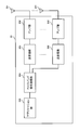
- FIG. 14 is a diagram illustrating an example of a functional configuration of a user terminal according to an embodiment of the present invention.
- the functional blocks of the characteristic part in the present embodiment are mainly shown, and the user terminal 20 also has other functional blocks necessary for wireless communication.
- the baseband signal processing unit 204 included in the user terminal 20 includes at least a control unit 401, a transmission signal generation unit 402, a mapping unit 403, a reception signal processing unit 404, and a measurement unit 405. Note that these configurations may be included in the user terminal 20, and some or all of the configurations may not be included in the baseband signal processing unit 204.
- the control unit 401 controls the entire user terminal 20.
- the control unit 401 can be composed of a controller, a control circuit, or a control device described based on common recognition in the technical field according to the present invention.
- the control unit 401 controls, for example, signal generation by the transmission signal generation unit 402, signal allocation by the mapping unit 403, and the like.
- the control unit 401 also controls signal reception processing by the reception signal processing unit 404, signal measurement by the measurement unit 405, and the like.
- the control unit 401 receives, from the received signal processing unit 404, a downlink control signal (for example, a signal transmitted by PDCCH / EPDCCH) and a downlink data signal (for example, a signal transmitted by PDSCH) transmitted from the radio base station 10. get.
- the control unit 401 controls generation of an uplink control signal (eg, delivery confirmation information) and / or an uplink data signal based on a result of determining whether or not retransmission control is required for the downlink control signal and / or downlink data signal. To do.
- the control unit 401 Based on information on partial RBs (first resource units) made up of subcarriers less than a predetermined number (for example, 12), the control unit 401 completes RBs (first RBs) made up of the same number of subcarriers as the predetermined number. 2 resource unit) is specified, and communication using the partial RB in the frequency domain is controlled.
- the subcarriers constituting the partial RB may include discontinuous subcarriers.
- the control unit 401 may perform control to map the reference signal used in the partial RB according to a resource mapping rule different from the resource mapping rule for the reference signal used in the complete RB.
- the control unit 401 may map the data to the resource of the complete RB in preference to the resource of the partial RB.
- control unit 401 may determine the transport block size and / or transmission power of the data based on the number of resources obtained by converting the resource of the scheduled partial RB into a complete RB. Good.
- the control unit 401 may perform control so that downlink control channel candidates are not monitored in the region belonging to the partial RB.
- the control unit 401 may perform control assuming that communication using the partial RB is limited to a predetermined radio access scheme in the uplink.
- the control unit 401 may use a sequence shorter or longer than the reference signal sequence for full RB as the reference signal sequence for partial RB.
- control unit 401 may update parameters used for control based on the information.
- the transmission signal generation unit 402 generates an uplink signal (uplink control signal, uplink data signal, uplink reference signal, etc.) based on an instruction from the control unit 401 and outputs the uplink signal to the mapping unit 403.
- the transmission signal generation unit 402 can be configured by a signal generator, a signal generation circuit, or a signal generation device described based on common recognition in the technical field according to the present invention.
- the transmission signal generation unit 402 generates an uplink control signal related to delivery confirmation information, channel state information (CSI), and the like based on an instruction from the control unit 401, for example. In addition, the transmission signal generation unit 402 generates an uplink data signal based on an instruction from the control unit 401. For example, the transmission signal generation unit 402 is instructed by the control unit 401 to generate an uplink data signal when the UL grant is included in the downlink control signal notified from the radio base station 10.
- CSI channel state information
- the mapping unit 403 maps the uplink signal generated by the transmission signal generation unit 402 to a radio resource based on an instruction from the control unit 401, and outputs the radio signal to the transmission / reception unit 203.
- the mapping unit 403 can be configured by a mapper, a mapping circuit, or a mapping device described based on common recognition in the technical field according to the present invention.
- the reception signal processing unit 404 performs reception processing (for example, demapping, demodulation, decoding, etc.) on the reception signal input from the transmission / reception unit 203.
- the received signal is, for example, a downlink signal (downlink control signal, downlink data signal, downlink reference signal, etc.) transmitted from the radio base station 10.
- the reception signal processing unit 404 can be configured by a signal processor, a signal processing circuit, or a signal processing device described based on common recognition in the technical field according to the present invention. Further, the reception signal processing unit 404 can constitute a reception unit according to the present invention.
- the reception signal processing unit 404 outputs the information decoded by the reception processing to the control unit 401.
- the reception signal processing unit 404 outputs, for example, broadcast information, system information, RRC signaling, DCI, and the like to the control unit 401.
- the reception signal processing unit 404 outputs the reception signal and / or the signal after reception processing to the measurement unit 405.
- the measurement unit 405 performs measurement on the received signal.
- the measurement unit 405 performs measurement using the downlink reference signal transmitted from the radio base station 10.
- the measurement part 405 can be comprised from the measuring device, measurement circuit, or measurement apparatus demonstrated based on common recognition in the technical field which concerns on this invention.
- the measurement unit 405 may perform RRM measurement, CSI measurement, and the like based on the received signal.
- the measurement unit 405 may measure received power (for example, RSRP), received quality (for example, RSRQ, SINR), power intensity (for example, RSSI), downlink channel information (for example, CSI), and the like.
- the measurement result may be output to the control unit 401.
- each functional block may be realized by one device physically and / or logically coupled, and two or more devices physically and / or logically separated may be directly and / or indirectly. (For example, wired and / or wireless) and may be realized by these plural devices.
- a radio base station, a user terminal, etc. in an embodiment of the present invention may function as a computer that performs processing of the radio communication method of the present invention.
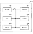
- FIG. 15 is a diagram illustrating an example of a hardware configuration of a radio base station and a user terminal according to an embodiment of the present invention.
- the wireless base station 10 and the user terminal 20 described above may be physically configured as a computer device including a processor 1001, a memory 1002, a storage 1003, a communication device 1004, an input device 1005, an output device 1006, a bus 1007, and the like. Good.
- the term “apparatus” can be read as a circuit, a device, a unit, or the like.
- the hardware configurations of the radio base station 10 and the user terminal 20 may be configured to include one or a plurality of each device illustrated in the figure, or may be configured not to include some devices.
- processor 1001 may be implemented by one or more chips.
- each function in the radio base station 10 and the user terminal 20 reads predetermined software (program) on hardware such as the processor 1001 and the memory 1002, so that the processor 1001 performs computation and communication by the communication device 1004. It is realized by controlling the reading and / or writing of data in the memory 1002 and the storage 1003.
- the processor 1001 controls the entire computer by operating an operating system, for example.
- the processor 1001 may be configured by a central processing unit (CPU) including an interface with peripheral devices, a control device, an arithmetic device, a register, and the like.
- CPU central processing unit
- the baseband signal processing unit 104 (204) and the call processing unit 105 described above may be realized by the processor 1001.
- the processor 1001 reads programs (program codes), software modules, data, and the like from the storage 1003 and / or the communication device 1004 to the memory 1002, and executes various processes according to these.
- programs program codes
- software modules software modules
- data data
- the like data
- the control unit 401 of the user terminal 20 may be realized by a control program stored in the memory 1002 and operated by the processor 1001, and may be realized similarly for other functional blocks.
- the memory 1002 is a computer-readable recording medium such as a ROM (Read Only Memory), an EPROM (Erasable Programmable ROM), an EEPROM (Electrically EPROM), a RAM (Random Access Memory), or any other suitable storage medium. It may be configured by one.
- the memory 1002 may be called a register, a cache, a main memory (main storage device), or the like.
- the memory 1002 can store programs (program codes), software modules, and the like that can be executed to implement the wireless communication method according to an embodiment of the present invention.
- the storage 1003 is a computer-readable recording medium such as a flexible disk, a floppy (registered trademark) disk, a magneto-optical disk (for example, a compact disk (CD-ROM (Compact Disc ROM)), a digital versatile disk, Blu-ray® disk), removable disk, hard disk drive, smart card, flash memory device (eg, card, stick, key drive), magnetic stripe, database, server, or other suitable storage medium It may be constituted by.
- the storage 1003 may be referred to as an auxiliary storage device.
- the communication device 1004 is hardware (transmission / reception device) for performing communication between computers via a wired and / or wireless network, and is also referred to as a network device, a network controller, a network card, a communication module, or the like.
- the communication device 1004 includes, for example, a high-frequency switch, a duplexer, a filter, a frequency synthesizer, etc., in order to realize frequency division duplex (FDD) and / or time division duplex (TDD). It may be configured.
- FDD frequency division duplex
- TDD time division duplex
- the transmission / reception antenna 101 (201), the amplifier unit 102 (202), the transmission / reception unit 103 (203), the transmission path interface 106, and the like described above may be realized by the communication device 1004.
- the input device 1005 is an input device (for example, a keyboard, a mouse, a microphone, a switch, a button, a sensor, etc.) that accepts an input from the outside.
- the output device 1006 is an output device (for example, a display, a speaker, an LED (Light Emitting Diode) lamp, etc.) that performs output to the outside.
- the input device 1005 and the output device 1006 may have an integrated configuration (for example, a touch panel).
- each device such as the processor 1001 and the memory 1002 is connected by a bus 1007 for communicating information.
- the bus 1007 may be configured with a single bus or may be configured with different buses between apparatuses.
- the radio base station 10 and the user terminal 20 include a microprocessor, a digital signal processor (DSP), an ASIC (Application Specific Integrated Circuit), a PLD (Programmable Logic Device), an FPGA (Field Programmable Gate Array), and the like. It may be configured including hardware, and a part or all of each functional block may be realized by the hardware. For example, the processor 1001 may be implemented by at least one of these hardware.
- DSP digital signal processor
- ASIC Application Specific Integrated Circuit
- PLD Programmable Logic Device
- FPGA Field Programmable Gate Array
- the channel and / or symbol may be a signal (signaling).
- the signal may be a message.
- the reference signal may be abbreviated as RS (Reference Signal), and may be referred to as a pilot, a pilot signal, or the like depending on an applied standard.
- a component carrier CC: Component Carrier
- CC Component Carrier
- the radio frame may be configured with one or a plurality of periods (frames) in the time domain.
- Each of the one or more periods (frames) constituting the radio frame may be referred to as a subframe.
- a subframe may be composed of one or more slots in the time domain.
- the subframe may have a fixed time length (eg, 1 ms) that does not depend on the neurology.
- the slot may be configured with one or a plurality of symbols (OFDM (Orthogonal Frequency Division Multiplexing) symbol, SC-FDMA (Single Carrier Frequency Division Multiple Access) symbol, etc.) in the time domain).
- OFDM Orthogonal Frequency Division Multiplexing
- SC-FDMA Single Carrier Frequency Division Multiple Access
- the slot may be a time unit based on the numerology.
- the slot may include a plurality of minislots that may be time units based on pneumatics. Each minislot may be composed of one or more symbols in the time domain.
- Radio frame, subframe, slot, minislot, and symbol all represent time units when transmitting signals. Different names may be used for the radio frame, subframe, slot, minislot, and symbol.
- one subframe may be called a transmission time interval (TTI)
- TTI transmission time interval
- a plurality of consecutive subframes may be called a TTI
- TTI slot or one minislot
- a unit representing TTI may be called a slot, a minislot, or the like instead of a subframe.
- TTI means, for example, a minimum time unit for scheduling in wireless communication.
- a radio base station performs scheduling for assigning radio resources (frequency bandwidth, transmission power, etc. that can be used in each user terminal) to each user terminal in units of TTI.
- the definition of TTI is not limited to this.
- the TTI may be a transmission time unit of a channel-encoded data packet (transport block), a code block, and / or a code word, or may be a processing unit such as scheduling or link adaptation.
- a time interval for example, the number of symbols
- a transport block, a code block, and / or a code word is actually mapped may be shorter than the TTI.
- one or more TTIs may be the minimum scheduling unit. Further, the number of slots (the number of mini-slots) constituting the minimum time unit of the scheduling may be controlled.
- a TTI having a time length of 1 ms may be called a normal TTI (TTI in LTE Rel. 8-12), a normal TTI, a long TTI, a normal subframe, a normal subframe, or a long subframe.
- TTI shorter than a normal TTI may be called a shortened TTI, a short TTI, a partial TTI (partial or fractional TTI), a shortened subframe, a short subframe, or the like.
- a long TTI (eg, normal TTI, subframe, etc.) may be read as a TTI having a time length exceeding 1 ms, and a short TTI (eg, shortened TTI) is less than the TTI length of the long TTI and 1 ms. It may be replaced with a TTI having the above TTI length.
- a resource block is a resource allocation unit in the time domain and the frequency domain, and may include one or a plurality of continuous subcarriers (subcarriers) in the frequency domain. Further, the RB may include one or a plurality of symbols in the time domain, and may have a length of 1 slot, 1 mini slot, 1 subframe, or 1 TTI. One TTI and one subframe may each be composed of one or a plurality of resource blocks.
- One or more RBs include physical resource blocks (PRB), sub-carrier groups (SCG), resource element groups (REG), PRB pairs, RB pairs, etc. May be called.
- the resource block may be composed of one or a plurality of resource elements (RE: Resource Element).
- RE Resource Element
- 1RE may be a radio resource region of 1 subcarrier and 1 symbol.
- the structure of the above-described radio frame, subframe, slot, minislot, symbol, etc. is merely an example.
- the number of subframes included in a radio frame, the number of slots per subframe or radio frame, the number of minislots included in the slot, the number of symbols and RBs included in the slot or minislot, and the RB The number of subcarriers, the number of symbols in the TTI, the symbol length, the cyclic prefix (CP) length, and the like can be variously changed.
- information, parameters, and the like described in this specification may be represented by absolute values, may be represented by relative values from a predetermined value, or may be represented by other corresponding information.
- the radio resource may be indicated by a predetermined index.
- mathematical formulas and the like using these parameters may differ from those explicitly disclosed herein.
- PUCCH Physical Uplink Control Channel
- PDCCH Physical Downlink Control Channel
- information elements can be identified by any suitable name, so the various channels and information elements assigned to them.
- the name is not limiting in any way.
- information, signals, etc. can be output from the upper layer to the lower layer and / or from the lower layer to the upper layer.
- Information, signals, and the like may be input / output via a plurality of network nodes.
- the input / output information, signals, etc. may be stored in a specific location (for example, a memory), or may be managed by a management table. Input / output information, signals, and the like can be overwritten, updated, or added. The output information, signals, etc. may be deleted. Input information, signals, and the like may be transmitted to other devices.
- information notification includes physical layer signaling (eg, downlink control information (DCI), uplink control information (UCI)), upper layer signaling (eg, RRC (Radio Resource Control) signaling), It may be implemented by broadcast information (Master Information Block (MIB), System Information Block (SIB), etc.), MAC (Medium Access Control) signaling), other signals, or a combination thereof.
- DCI downlink control information
- UCI uplink control information
- RRC Radio Resource Control
- MIB Master Information Block
- SIB System Information Block
- MAC Medium Access Control
- the physical layer signaling may be referred to as L1 / L2 (Layer 1 / Layer 2) control information (L1 / L2 control signal), L1 control information (L1 control signal), or the like.
- the RRC signaling may be referred to as an RRC message, and may be, for example, an RRC connection setup (RRCConnectionSetup) message, an RRC connection reconfiguration (RRCConnectionReconfiguration) message, or the like.
- the MAC signaling may be notified by, for example, a MAC control element (MAC CE (Control Element)).
- notification of predetermined information is not limited to explicitly performed, but implicitly (for example, by not performing notification of the predetermined information or another (By notification of information).
- the determination may be performed by a value represented by 1 bit (0 or 1), or may be performed by a boolean value represented by true or false.
- the comparison may be performed by numerical comparison (for example, comparison with a predetermined value).
- software, instructions, information, etc. may be transmitted / received via a transmission medium.
- software can use websites, servers using wired technology (coaxial cable, fiber optic cable, twisted pair, digital subscriber line (DSL), etc.) and / or wireless technology (infrared, microwave, etc.) , Or other remote sources, these wired and / or wireless technologies are included within the definition of transmission media.
- system and “network” used in this specification are used interchangeably.
- base station BS
- radio base station eNB
- gNB gNodeB
- cell gNodeB
- cell group a base station
- carrier a base station
- component carrier a base station
- a base station may also be called in terms such as a fixed station, NodeB, eNodeB (eNB), access point, transmission point, reception point, femtocell, and small cell.
- the base station can accommodate one or a plurality of (for example, three) cells (also called sectors). If the base station accommodates multiple cells, the entire coverage area of the base station can be partitioned into multiple smaller areas, each smaller area being a base station subsystem (eg, an indoor small base station (RRH: The term “cell” or “sector” refers to part or all of the coverage area of a base station and / or base station subsystem that provides communication service in this coverage. Point to.
- RRH indoor small base station
- MS mobile station
- UE user equipment
- terminal may be used interchangeably.
- a base station may also be called in terms such as a fixed station, NodeB, eNodeB (eNB), access point, transmission point, reception point, femtocell, and small cell.
- NodeB NodeB
- eNodeB eNodeB
- access point transmission point
- reception point femtocell
- small cell small cell
- a mobile station is defined by those skilled in the art as a subscriber station, mobile unit, subscriber unit, wireless unit, remote unit, mobile device, wireless device, wireless communication device, remote device, mobile subscriber station, access terminal, mobile terminal, wireless It may also be called terminal, remote terminal, handset, user agent, mobile client, client or some other suitable terminology.
- the radio base station in this specification may be read by the user terminal.
- each aspect / embodiment of the present invention may be applied to a configuration in which communication between a radio base station and a user terminal is replaced with communication between a plurality of user terminals (D2D: Device-to-Device).
- the user terminal 20 may have a function that the wireless base station 10 has.
- words such as “up” and “down” may be read as “side”.
- the uplink channel may be read as a side channel.
- a user terminal in this specification may be read by a radio base station.
- the wireless base station 10 may have a function that the user terminal 20 has.
- the specific operation assumed to be performed by the base station may be performed by the upper node in some cases.
- various operations performed for communication with a terminal may be performed by one or more network nodes other than the base station and the base station (for example, It is obvious that this can be done by MME (Mobility Management Entity), S-GW (Serving-Gateway), etc., but not limited thereto) or a combination thereof.
- MME Mobility Management Entity
- S-GW Serving-Gateway
- each aspect / embodiment described in this specification may be used alone, in combination, or may be switched according to execution.
- the order of the processing procedures, sequences, flowcharts, and the like of each aspect / embodiment described in this specification may be changed as long as there is no contradiction.
- the methods described herein present the elements of the various steps in an exemplary order and are not limited to the specific order presented.
- Each aspect / embodiment described herein includes LTE (Long Term Evolution), LTE-A (LTE-Advanced), LTE-B (LTE-Beyond), SUPER 3G, IMT-Advanced, 4G (4th generation mobile). communication system), 5G (5th generation mobile communication system), FRA (Future Radio Access), New-RAT (Radio Access Technology), NR (New Radio), NX (New radio access), FX (Future generation radio access), GSM (registered trademark) (Global System for Mobile communications), CDMA2000, UMB (Ultra Mobile Broadband), IEEE 802.11 (Wi-Fi (registered trademark)), IEEE 802.16 (WiMAX (registered trademark)), IEEE 802 .20, UWB (Ultra-WideBand), Bluetooth (registered trademark), The present invention may be applied to a system using other appropriate wireless communication methods and / or a next generation system extended based on these.
- the phrase “based on” does not mean “based only on”, unless expressly specified otherwise. In other words, the phrase “based on” means both “based only on” and “based at least on.”
- any reference to elements using designations such as “first”, “second”, etc. as used herein does not generally limit the amount or order of those elements. These designations can be used herein as a convenient way to distinguish between two or more elements. Thus, reference to the first and second elements does not mean that only two elements can be employed or that the first element must precede the second element in some way.
- determining may encompass a wide variety of actions. For example, “determination” means calculating, computing, processing, deriving, investigating, looking up (eg, table, database or other data). It may be considered to “judge” (search in structure), ascertaining, etc.
- “determination (decision)” includes receiving (for example, receiving information), transmitting (for example, transmitting information), input (input), output (output), access ( accessing) (e.g., accessing data in memory), etc. may be considered to be “determining”. Also, “determination” is considered to be “determination (resolving)”, “selecting”, “choosing”, “establishing”, “comparing”, etc. Also good. That is, “determination (determination)” may be regarded as “determination (determination)” of some operation.
Abstract
既存のリソースブロックと異なるサブキャリア数で構成される新たな制御単位が用いられる場合であっても、当該新たな制御単位を用いて好適に通信すること。本発明の一態様に係るユーザ端末は、所定の数より少ないサブキャリアから成る第1のリソース単位に関する情報を受信する受信部と、前記情報に基づいて、前記所定の数と同じ数のサブキャリアから成る第2のリソース単位の周波数領域を特定し、当該周波数領域内での前記第1のリソース単位を用いる通信を制御する制御部と、を有することを特徴とする。
Description
本発明は、次世代移動通信システムにおけるユーザ端末及び無線通信方法に関する。
UMTS(Universal Mobile Telecommunications System)ネットワークにおいて、更なる高速データレート、低遅延などを目的としてロングタームエボリューション(LTE:Long Term Evolution)が仕様化された(非特許文献1)。また、LTE(LTE Rel.8又は9ともいう)からの更なる広帯域化及び高速化を目的として、LTE-A(LTEアドバンスト、LTE Rel.10、11又は12ともいう)が仕様化され、LTEの後継システム(例えば、FRA(Future Radio Access)、5G(5th generation mobile communication system)、5G+(plus)、NR(New Radio)、NX(New radio access)、New RAT(Radio Access Technology)、FX(Future generation radio access)、LTE Rel.13、14又は15以降などともいう)も検討されている。
LTE Rel.10/11では、広帯域化を図るために、複数のコンポーネントキャリア(CC:Component Carrier)を統合するキャリアアグリゲーション(CA:Carrier Aggregation)が導入されている。各CCは、LTE Rel.8のシステム帯域を一単位として構成される。また、CAでは、同一の無線基地局(eNB(eNodeB)、基地局(BS:Base Station)などと呼ばれる)の複数のCCがユーザ端末(UE:User Equipment)に設定される。
一方、LTE Rel.12では、異なる無線基地局の複数のセルグループ(CG:Cell Group)がUEに設定されるデュアルコネクティビティ(DC:Dual Connectivity)も導入されている。各セルグループは、少なくとも一つのセル(CC)で構成される。DCでは、異なる無線基地局の複数のCCが統合されるため、DCは、基地局間CA(Inter-eNB CA)などとも呼ばれる。
また、LTE Rel.8-12では、下り(DL:Downlink)伝送と上り(UL:Uplink)伝送とを異なる周波数帯で行う周波数分割複信(FDD:Frequency Division Duplex)と、下り伝送と上り伝送とを同じ周波数帯で時間的に切り替えて行う時分割複信(TDD:Time Division Duplex)とが導入されている。
また、LTE Rel.8-12では、HARQ(Hybrid Automatic Repeat reQuest)に基づくデータの再送制御が利用されている。UE及び/又は基地局は、送信したデータに関する送達確認情報(HARQ-ACK、ACK/NACKなどともいう)を受信し、当該情報に基づいてデータの再送を判断する。
将来の無線通信システム(例えば、5G、NR)は、様々な無線通信サービスを、それぞれ異なる要求条件(例えば、超高速、大容量、超低遅延など)を満たすように実現することが期待されている。
例えば、5G/NRでは、eMBB(enhanced Mobile Broad Band)、IoT(Internet of Things)、mMTC(massive Machine Type Communication)、M2M(Machine To Machine)、URLLC(Ultra Reliable and Low Latency Communications)などと呼ばれる無線通信サービスの提供が検討されている。
既存のLTEでは、リソースブロック(RB:Resource Block)と呼ばれる無線リソース単位を用いてスケジューリングなどの制御が行われている。一方、5G/NRでは、既存のRBより少ないサブキャリア数で構成される部分RB(Fractional RB)が検討されている。しかしながら、部分RBの具体的な設定、リソース割り当てなどについては、まだ検討されていない。このため、適切な方法を規定しなければ、通信品質、スループットなどが劣化するおそれがある。
本発明はかかる点に鑑みてなされたものであり、既存のリソースブロックと異なるサブキャリア数で構成される新たな制御単位が用いられる場合であっても、当該新たな制御単位を用いて好適に通信できるユーザ端末及び無線通信方法を提供することを目的の1つとする。
本発明の一態様に係るユーザ端末は、所定の数より少ないサブキャリアから成る第1のリソース単位に関する情報を受信する受信部と、前記情報に基づいて、前記所定の数と同じ数のサブキャリアから成る第2のリソース単位の周波数領域を特定し、当該周波数領域内での前記第1のリソース単位を用いる通信を制御する制御部と、を有することを特徴とする。
本発明によれば、既存のリソースブロックと異なるサブキャリア数で構成される新たな制御単位が用いられる場合であっても、当該新たな制御単位を用いて好適に通信できる。
既存のLTEでは、リソースブロック(RB:Resource Block)と呼ばれる無線リソース単位を用いてスケジューリングなどの制御が行われている。1RBは、周波数方向に12サブキャリア(=180kHz)、時間方向に0.5ms(=7シンボル)の範囲から成るリソースで構成される。
なお、リソースブロックは、サブキャリアグループ(SCG:Sub-Carrier Group)、リソースエレメントグループ(REG:Resource Element Group)、物理リソースブロック(PRB:Physical RB)などと呼ばれてもよい。また、1サブキャリアの周波数幅及び1OFDMシンボルの期間で構成される無線リソース領域は、リソースエレメント(RE:Resource Element)と呼ばれる。
ところで、5G/NRでは、柔軟なニューメロロジー及び周波数の利用をサポートし、動的なフレーム構成を実現することが求められている。ここで、ニューメロロジーとは、周波数領域及び/又は時間領域に関する通信パラメータ(例えば、サブキャリア間隔(SCS:Subcarrier Spacing)、帯域幅、シンボル長、サイクリックプレフィックス(CP:Cyclic Prefix)長、送信時間間隔(TTI:Transmission Time Interval)長、TTIあたりのシンボル数、無線フレーム構成、フィルタリング処理、ウィンドウイング処理などの少なくとも1つ)のことをいう。
例えば、NRでは、複数のニューメロロジーをサポートし、異なるサービスに別々のニューメロロジーを適用することが検討されている。例えば、遅延削減のためURLLC向けに大きなSCSが用いられ、消費電力削減のためmMTC向けに小さなSCSが用いられることが考えられる。
5G/NRでは、既存のLTEのSCS(=15kHz)と異なるSCSの場合であっても、12サブキャリアから成るRB(完全RB(Full RB)、通常RBなどと呼ばれてもよい)を用いて制御することが検討されている。一方で、既存のRBより少ないサブキャリア数で構成される部分RB(Fractional RB)の利用が検討されている。図1を参照して、SCSの値に応じてRBの周波数リソースのサイズが異なることによる問題と、部分RB導入の効果と、を説明する。
図1は、部分RBが用いられる一例を示す図である。図1では、UEは所定幅(23RB分)のシステム帯域を設定されている。図1には、SCS=f0(例えば、15kHz)、2f0、4f0及び8f0それぞれの場合におけるリソースの割り当て例が示されている。
SCSがf0の場合には、完全RBのみを用いてシステム帯域幅を使い切るように無線リソースを割り当てることができる。SCSがf0以外の場合には、完全RBに足りない周波数領域が存在するため、完全RBのみを用いると、帯域幅を使い切るように無線リソースを割り当てることができない。一方、部分RBも用いることにより、帯域幅を使い切る割り当てが可能である。
しかしながら、部分RBの具体的な設定、リソースマッピング方法などについては、まだ検討されていない。このため、適切な方法を規定しなければ、部分RBを好適に利用することができず、通信品質、スループットなどが劣化するおそれがある。そこで、本発明者らは、部分RBを適切に用いるための技術を検討し、本発明を見出した。
以下、本発明に係る実施形態について、図面を参照して詳細に説明する。各実施形態に係る無線通信方法は、それぞれ単独で適用されてもよいし、組み合わせて適用されてもよい。
(無線通信方法)
<第1の実施形態>
第1の実施形態は、部分RBの構成に関する。部分RBの構成は、部分RBに関するパラメータ(例えば、部分RBに含まれるサブキャリア数、部分RBが割り当てられるRBインデックス、所定のRB内に占める部分RBの相対的な位置など)によって特定されてもよい。これらの構成の少なくとも一部は、ニューメロロジーごとに異なって決定されてもよい。例えばUEが複数のニューメロロジーを設定(configure)される場合には、部分RBに関するパラメータはニューメロロジーごと(例えばSCSごと)に設定されてもよい。
<第1の実施形態>
第1の実施形態は、部分RBの構成に関する。部分RBの構成は、部分RBに関するパラメータ(例えば、部分RBに含まれるサブキャリア数、部分RBが割り当てられるRBインデックス、所定のRB内に占める部分RBの相対的な位置など)によって特定されてもよい。これらの構成の少なくとも一部は、ニューメロロジーごとに異なって決定されてもよい。例えばUEが複数のニューメロロジーを設定(configure)される場合には、部分RBに関するパラメータはニューメロロジーごと(例えばSCSごと)に設定されてもよい。
部分RBが割り当てられるRBインデックスは、例えば完全RB単位のRBを示すインデックスであってもよいし、部分RB単位のRBを示すインデックスであってもよい。例えば、UEは、当該RBインデックスに基づいて、完全RBを特定し、当該完全RBの周波数領域内での部分RBを用いる通信を制御できる。
部分RBに含まれるサブキャリア数は、通常RBのサブキャリア数(例えば、12)に比べて小さい値であり、例えば10、8、6、又は3などであってもよい。ただし、所定のニューメロロジーにおいて通常RBが12より大きいサブキャリア数で構成される場合には、部分RBに含まれるサブキャリア数は12以上であってもよい。
所定のRB内に占める部分RBの相対的な位置は、例えば部分RBが含まれるRBの中で周波数が高い/低い(high/low)(つまり後述の図2のように描いた時に、左寄せになるか右寄せになるか)のように二値で表されてもよいし、所定のRBが開始する周波数リソースからのオフセット(サブキャリア数など)で表されてもよい。なお、二値としては、例えば左/右(left/right)で表されてもよい。この場合、「左」は周波数のより低い側のリソースを示してもよいし、逆により高い側のリソースを示してもよい。また、オフセットは、所定のRB(又は所定のサブバンド)内で最初にリソース割り当てがある(空でない)サブキャリアを特定する値であってもよい。
図2は、部分RBの構成の一例を示す図である。図2Aは、完全RBの例であり、12サブキャリア×7シンボルで構成されている。図2B及び2Cは、それぞれ部分RBの例であり、図中の左側(周波数が低い側)の領域の8サブキャリア及び6サブキャリアで構成されている。図2においては、部分RBを構成するサブキャリアは、連続して配置されている。
ここで、さらに積極的にリソースを割り当てる部分RBのリソースパターンも考えられる。例えば、当該パターンとして、所定のサブキャリア位置まで連続してサブキャリアを利用し、当該位置以降は2サブキャリアごとに1つのサブキャリアを利用するパターンを用いてもよい。このような1つおきのサブキャリア(every second subcarrier)にマッピングされるパターンについて、図3を参照して説明する。
図3は、部分RBの構成の別の一例を示す図である。図3Aは、10サブキャリアの部分RBの例であり、図3Bは、9サブキャリアの部分RBの例である。図3の各図においては、部分RBを構成する一部のサブキャリアは、非連続な(櫛状の)周波数リソースに配置されている。
具体的には、図3Aでは、上記所定のサブキャリア位置は左側から8サブキャリアであり、それ以降は2サブキャリアごとに左側のサブキャリアが部分RBとして利用される。図3Bでは、上記所定のサブキャリア位置は左側から6サブキャリアであり、それ以降は2サブキャリアごとに左側のサブキャリアが部分RBとして利用される。櫛状にマッピングされるサブキャリアは、2サブキャリアごとの右側のサブキャリアであってもよい。
このような非連続な周波数リソースを含む部分RB構成によれば、異なるニューメロロジー間で周波数分割多重(FDM:Frequency Division Multiplexing)する場合であっても、ガードバンドを小さくすることができる。例えば、当該部分RBを用いるニューメロロジーのSCS(例えば、15kHz)に比べて、FDMされるニューメロロジーのSCSが2倍である(例えば、30kHz)場合には、FDMされるニューメロロジー(隣接RB)からの干渉は、1つおきのサブキャリアにおいてゼロとみなすことができるためである。
なお、部分RBの両側(高周波側及び低周波側(左側及び右側))が非連続な構成としてもよい。また、部分RBを構成する全部のサブキャリアが非連続に配置されてもよい。例えば、部分RBは、1つおきに6サブキャリアを利用してもよい。この場合、上記所定のサブキャリア位置は、「ない」又は「端から0サブキャリアである」とも言える。また、非連続なサブキャリア配置は、1つおきにサブキャリアを利用する以外の配置であってもよいし、n(>1)個おきにサブキャリアを利用する配置などであってもよい。
部分RBに関するパラメータ(情報)は、準静的にUEに通知(設定)されてもよい。UEは、準静的に設定されるRBがスケジュールされる場合、当該RBが部分RBであると想定(判断)してもよい。準静的な通知は、上位レイヤシグナリング(例えば、RRC(Radio Resource Control)シグナリング、ブロードキャスト情報(マスタ情報ブロック(MIB:Master Information Block)、システム情報ブロック(SIB:System Information Block)など)、MAC(Medium Access Control)シグナリング)によって行われてもよい。
また、部分RBに関するパラメータは、動的にUEに通知されてもよい。UEは、通知される物理レイヤシグナリング(例えば、下り制御情報(DCI:Downlink Control Information))によって、スケジュールされるRBのうち1つ以上のRBが部分RBであると想定(判断)してもよい。
部分RBに関するパラメータは、当該部分RBが周波数方向に非連続なサブキャリアを含むか否かに関する情報を含んでもよい。また、部分RBに関するパラメータは、当該部分RBが周波数方向に非連続なサブキャリアを含む場合には、上述の所定のサブキャリア位置(ガードバンドでないサブキャリアを特定する情報)及び/又は非連続なサブキャリアが部分RBのどちら側(高及び/又は低、左及び/又は右など)で用いられるかの情報を含んでもよい。
なお、部分RBに関するパラメータは、ニューメロロジーに関連付けられて決定されてもよいし、他の指標に基づいて決定されてもよい。この場合、UEは、設定されるニューメロロジー、他の指標などに基づいて、所定のキャリアで利用される部分RBに関するパラメータを取得してもよい。他の指標は、例えば、キャリアのサービスタイプ(eMBB、URLLCなど)であってもよい。
なお、第1の実施形態は、リンクの方向によらず(例えば、下りリンク及び上りリンクのいずれでも)、部分RBの設定に適用できる。上りリンクの設定については、さらに後述の第6の実施形態でも触れる。
以上説明した第1の実施形態によれば、UE及び/又は基地局が、適切に用いる部分RBの構成を判断することができる。
<第2の実施形態>
第2の実施形態は、部分RBの領域に割り当てられる参照信号(以下、部分RB用RSともいう)のリソースマッピングに関する。UEは、部分RB用RSを、部分RBで送信されるデータ及び/又は制御信号の受信処理(復調、復号など)に用いてもよいし、測定(例えば、RRM(Radio Resource Management)測定、CSI(Channel State Information)測定など)に用いてもよい。第2の実施形態は、さらに3つに大別される(実施形態2.1-2.3)。
第2の実施形態は、部分RBの領域に割り当てられる参照信号(以下、部分RB用RSともいう)のリソースマッピングに関する。UEは、部分RB用RSを、部分RBで送信されるデータ及び/又は制御信号の受信処理(復調、復号など)に用いてもよいし、測定(例えば、RRM(Radio Resource Management)測定、CSI(Channel State Information)測定など)に用いてもよい。第2の実施形態は、さらに3つに大別される(実施形態2.1-2.3)。
[実施形態2.1]
実施形態2.1では、部分RB用RSは、完全RB用RSと異なるリソースマッピング方法(規則)を用いてマッピングされる。つまり、部分RBでは、完全RBであればRSがマッピングされるリソースにRSをマッピングしなくてもよいし、逆に完全RBであればRSがマッピングされないリソースにRSをマッピングしてもよい。また、部分RB用RSは、完全RB用RSと一部重複するリソースにマッピングされてもよい。
実施形態2.1では、部分RB用RSは、完全RB用RSと異なるリソースマッピング方法(規則)を用いてマッピングされる。つまり、部分RBでは、完全RBであればRSがマッピングされるリソースにRSをマッピングしなくてもよいし、逆に完全RBであればRSがマッピングされないリソースにRSをマッピングしてもよい。また、部分RB用RSは、完全RB用RSと一部重複するリソースにマッピングされてもよい。
部分RBに割り当てられる所定のRSの個数は、チャネル推定精度の維持のため、完全RBに割り当てられる当該所定のRSの個数と同じにすることが好ましいが、異なってもよい(例えば、完全RBに対する当該部分RBのリソースサイズ(リソースエレメント数)に基づいて、増加又は減少されてもよい)。
図4は、実施形態2.1における部分RB用RSのマッピングの一例を示す図である。図4Aは、完全RBの比較例であり、2つのアンテナポート(アンテナポートX、Y)の4つずつのRSがマッピングされるリソースが示されている。本例では、完全RBの先頭シンボルにRSがマッピングされるものとするが、これに限られない。また、RSのアンテナポート数も任意の数であってもよい。
図4B及び4Cは、先行配置RS(front-loaded RS)の一例を示す図である。先行配置RSは、部分RBのうち早い段階(例えば、1シンボル目、2シンボル目など)で送信される。図4Bは、8サブキャリアの部分RBであり、図4Cは、6サブキャリアの部分RBである。
図4Bでは、ポートあたりのRBの個数は減少するものの、完全RBと同様に先頭シンボルでRSが送信される。図4Cでは、ポートあたりのRBの個数を維持することができる。
図4D及び4Eは、分散RS(distributed RS)の一例を示す図である。分散RSは、部分RBのうち時間的に非連続のリソースで送信される。図4Dは、8サブキャリアの部分RBであり、図4Eは、6サブキャリアの部分RBである。図4D及び4Eでは、ポートあたりのRBの個数を維持することができる。
なお、第1の実施形態で述べた非連続な周波数リソースを含む部分RBにおいては、当該非連続な周波数リソースに部分RB用RSがマッピングされてもよい。
実施形態2.1によれば、UEは部分RBに閉じて送信又は受信処理を行うことができる。
[実施形態2.2]
実施形態2.2では、部分RB用RSは、完全RB用RSと同じリソースにマッピングされる。つまり、実施形態2.2では、部分RB用RSのリソース(RE)は、完全RB用RSのリソース(RE)のサブセットである。
実施形態2.2では、部分RB用RSは、完全RB用RSと同じリソースにマッピングされる。つまり、実施形態2.2では、部分RB用RSのリソース(RE)は、完全RB用RSのリソース(RE)のサブセットである。
図5は、実施形態2.2における部分RB用RSのマッピングの一例を示す図である。部分RBは6サブキャリアの周波数リソースを有するものとするが、これに限られない。実施形態2.2では、部分RBにおいて、完全RBだったとしたらマッピングされていた信号(データ、RS、制御信号など)のREは、パンクチャ又はレートマッチされる。
また、実施形態2.2においては、部分RBは、別にスケジュールされる完全RBに隣接してスケジュールされる。ここで、当該部分RBは、隣接する完全RBと同じプリコーディングが適用されるものとしてもよい。この場合、UEは、部分RB及び隣接する完全RBの一方又は両方のRSを用いて、部分RBに含まれるデータの受信処理を実施することができる。
実施形態2.2によれば、部分RBに含まれるRSのみを用いるとチャネル推定精度が劣化するおそれがあるのに対して、隣接する完全RBのRSも用いることで、チャネル推定精度の劣化を抑制できる。また、UEは完全RB及び部分RBについて同じ規則に従ってRSをマッピングするため、処理負荷の増大を抑制できる。
[実施形態2.3]
実施形態2.3では、部分RB用RSは、定義されない。このため、実施形態2.3では、部分RBはRSのリソース(RE)を含まない。
実施形態2.3では、部分RB用RSは、定義されない。このため、実施形態2.3では、部分RBはRSのリソース(RE)を含まない。
図6は、実施形態2.3における部分RB用RSのマッピングの一例を示す図である。図6は図5とほぼ同様の図であるため、以下では主に差異点を説明する。
実施形態2.3においては、実施形態2.2と同様に、部分RBは、別にスケジュールされる完全RBに隣接してスケジュールされ、当該完全RBと同じプリコーディングが適用されるものとすることが好ましい。UEは、隣接する完全RBのRSを用いて、部分RBに含まれるデータの受信処理を実施することができる。
部分RBにおいて、完全RBだったとしたらRSがマッピングされていたリソースには、データ信号、制御信号などのRS以外の信号がマッピングされてもよいし、信号がマッピングされなくてもよい(REをヌルとする、無送信とする)。また、UEは、部分RBにおいて、完全RBだったとしたらRSがマッピングされていたリソースを無視してもよい(受信処理を行わなくてもよい)。
実施形態2.3によれば、部分RBにおける周波数利用効率を向上することができる。
以上説明した第2の実施形態によれば、所定の参照信号を用いて、部分RBに関する処理を適切に実施することができる。
<第3の実施形態>
第3の実施形態は、部分RBにおけるデータのリソースマッピング規則に関する。第3の実施形態に係るデータのマッピング方法は、周波数方向にまずマッピングする方法(frequency-first and time-second mapping)と、時間方向にまずマッピングする方法(time-first and frequency-second mapping)と、がある。前者は周波数優先マッピングと呼ばれてもよいし、後者は時間優先マッピングと呼ばれてもよい。
第3の実施形態は、部分RBにおけるデータのリソースマッピング規則に関する。第3の実施形態に係るデータのマッピング方法は、周波数方向にまずマッピングする方法(frequency-first and time-second mapping)と、時間方向にまずマッピングする方法(time-first and frequency-second mapping)と、がある。前者は周波数優先マッピングと呼ばれてもよいし、後者は時間優先マッピングと呼ばれてもよい。
所定の領域において周波数優先マッピングを用いてデータをマッピングする場合、当該領域の最小のサブキャリアインデックス及び最小のシンボルインデックスのREに、最初のデータがマッピングされる。そして、後続のデータは、周波数が増大する方向にマッピングされていき、当該領域の最大の周波数に達すると、次のシンボルインデックスの最小サブキャリアインデックスのREに移動し、同様の処理を行っていく。
時間優先マッピングは、周波数優先マッピングの周波数(サブキャリア)と時間(シンボル)とを入れ替えた方法に等しい。なお、マッピングを開始するサブキャリア及び/又はシンボルは、最小のものに限られず、所定のRBに含まれる任意のREであってもよい。
図7は、第3の実施形態における部分RBのためのデータのリソースマッピングパターンの一例を示す図である。図7においては、データが1つ以上の完全RB及び当該完全RBの両端に隣接する2つの部分RBにマッピングされる例(完全RB及び部分RBが同時に(重複する時間リソースについて)スケジュールされる例)を示すが、完全RB及び部分RBの数、位置などは、これに限られない。
周波数優先マッピングの場合には、例えば図7A又は7Bのような規則に従ってもよい。図7Aに示すように、部分RBの利用の有無に関わらず、割り当てられる全RBについてデータを周波数優先マッピングしてもよい。また、図7Bに示すように、完全RBの領域に閉じてデータを周波数優先マッピングした後、部分RBの領域に閉じて後続のデータを周波数優先マッピングしてもよい。
時間優先マッピングの場合には、例えば図7C又は7Dのような規則に従ってもよい。図7Cに示すように、部分RBの利用の有無に関わらず、割り当てられる全RBについてデータを時間優先マッピングしてもよい。また、図7Dに示すように、完全RBの領域に閉じてデータを時間優先マッピングした後、部分RBの領域に閉じて後続のデータを時間優先マッピングしてもよい。
図7B及び7Dに示したように、部分RBより優先して(先に)完全RBにデータをマッピングする場合、部分RBで送信されるデータは、再送/合成用のソフトバッファの後ろ側に位置することとなる。ソフトバッファの後ろ側のデータは、再送の際に送信又は合成されない(削られる)場合もある。また、部分RBは、所定の帯域(例えば、システム帯域)の端などに位置し、隣接する別のニューメロロジーの信号から干渉を受けやすい(つまり、受信品質が良くない)と想定される。
このため、完全RBに先にデータをマッピングすることで、誤りが発生しやすい部分RBのデータをソフトバッファの後ろ側に蓄えることができる。これにより、再送のHARQ性能の低減を抑制できる。
また、図7B及び7Dのマッピング方法の場合、例えば部分RBの数、サイズなどの少なくとも1つが再送中に変動しても、レートマッチングを容易に適用することができる。
なお、図7B及び7Dとは逆に、完全RBより優先して(先に)部分RBにデータをマッピングしてもよい。すなわち、部分RBの領域に閉じてデータを周波数又は時間優先マッピングした後、完全RBの領域に閉じて後続のデータを周波数又は時間優先マッピングしてもよい。
再送の際には、初回送信及び/又は別の再送の場合と、適用するリソースマッピングパターンを異ならせてもよい(ホッピング及び/又はスイッチングしてもよい)。例えば、初回送信のマッピングが所定のRB(例えば、一番左の完全RB)から開始される場合であっても、再送時のマッピングは当該所定のRBよりずれたRB(例えば、一番左から3つ目の完全RB)から開始されてもよい。このようにすることで、再送時のデータが周波数方向に巡回シフトされることとなり、一部のデータだけが帯域の端にマッピングされ干渉を受け続けるという事態を抑制できる。
UE及び/又は基地局は、部分RBを用いる際、HARQのソフト合成に、チェイス合成(chase combining)を利用してもよいし、IR(Incremental Redundancy)を利用してもよい。チェイス合成は、データ再送の際に、初回伝送の時に使用されたパリティビットと同一のパリティビットを送信する方式である。IRは、データ再送の際に、初回伝送の時に使用されたパリティビットと異なるパリティビットを送信する方式である。
UE及び/又は基地局は、部分RBを含む信号を受信する場合、上述した少なくとも1つのマッピング方法を想定して受信処理を実施してもよい。また、UE及び/又は基地局は、通知される情報に従って特定したマッピング方法に基づいて受信処理を実施してもよい。
以上説明した第3の実施形態によれば、部分RBが含まれるスケジューリングがされる場合であっても、適切にデータのリソースマッピングを行うことができる。
<第4の実施形態>
第4の実施形態は、部分RBにおけるデータの変調方式及び符号化率(MCS:Modulation and Coding Scheme)、及びトランスポートブロックサイズ(TBS:Transport Block Size)に関する。第4の実施形態では、UE及び/又は基地局は、部分RBについてデータがスケジュールされる場合、スケジュールされる部分RBのリソースを完全RB単位に換算したリソース数に基づいて、当該データのTBSを判断する。
第4の実施形態は、部分RBにおけるデータの変調方式及び符号化率(MCS:Modulation and Coding Scheme)、及びトランスポートブロックサイズ(TBS:Transport Block Size)に関する。第4の実施形態では、UE及び/又は基地局は、部分RBについてデータがスケジュールされる場合、スケジュールされる部分RBのリソースを完全RB単位に換算したリソース数に基づいて、当該データのTBSを判断する。
例えば、部分RBを含むデータのTBSは、以下の式1で表される、換算後の完全RB数に基づいて得られてもよい。

ここで、Mはスケジュールされる完全RB数、Nはスケジュールされる部分RB数、nxはx番目のスケジュールされる部分RBが含むサブキャリア数である。
式1では、スケジュールされる部分RBをまとめた上で、完全RBに足りない分は切り上げて、完全RBの個数に換算している。一方で、部分RBを含むデータのTBSは、スケジュールされる完全RB数及びスケジュールされる部分RB数の和(=M+N)に基づいて得られてもよい。この場合、部分RBの数が決まればTBSを求めることができるため、例えば再送などでnxが変動し得る場合であっても一貫した制御を行うことができる。
また、部分RBにおけるデータのMCSは、上述のTBS、式1の値、M+Nの少なくとも1つに基づいて算出されてもよい。
以上説明した第4の実施形態によれば、部分RBが含まれるスケジューリングがされる場合であっても、適切にデータの変調、符号化などを行うことができる。
<第5の実施形態>
第5の実施形態は、部分RB利用時の下り制御チャネルに関する。第5の実施形態では、下り制御チャネルは完全RBのみに割り当てられ得る(実施形態5.1)か、下り制御チャネルは完全RB及び部分RBのいずれにも割り当てられ得る(実施形態5.2)。
第5の実施形態は、部分RB利用時の下り制御チャネルに関する。第5の実施形態では、下り制御チャネルは完全RBのみに割り当てられ得る(実施形態5.1)か、下り制御チャネルは完全RB及び部分RBのいずれにも割り当てられ得る(実施形態5.2)。
図8は、第5の実施形態における部分RB利用時の下り制御チャネル候補のリソースマッピングの一例を示す図である。図8は、図7同様の例を示すが、完全RB及び部分RBの数、位置などは、これに限られない。
図8Aは、実施形態5.1に対応する。下り制御チャネル候補は、部分RBには含まれない。このため、UEは、部分RBに属する領域では下り制御チャネル候補をモニタせず、完全RBに属する領域でのみ下り制御チャネル候補をモニタする。
図8Bは、実施形態5.2に対応する。下り制御チャネル候補は、部分RBに含まれてもよい。このため、UEは、完全RBに属する領域に加えて、部分RBに属する領域でも下り制御チャネル候補をモニタする。この場合、部分RBは下り制御チャネルのリソースユニットであるとみなされてもよい。
以上説明した第5の実施形態によれば、部分RBが設定される場合であっても、適切に下り制御情報の取得を行うことができる。
<第6の実施形態>
第6の実施形態は、部分RBの上りリンクへの適用に関する。
第6の実施形態は、部分RBの上りリンクへの適用に関する。
部分RBの利用は、下りリンクのみに制限されてもよい(実施形態6.1)。この場合、上りリンクの電力制御、信号処理などの複雑化を抑制することができる。
上りリンクで部分RBが利用される場合、部分RBの利用は上りリンク用の所定のアクセス方式(例えば、サイクリックプレフィックスOFDM(CP-OFDM:Cyclic Prefix Orthogonal Frequency Division Multiplexing)に制限されてもよい(実施形態6.2)。この場合、UEは、送信波形が他のアクセス方式(例えば、DFT拡散OFDM(DFT-S-OFDM:Discrete Fourier Transform Spread Orthogonal Frequency Division Multiplexing))であるときには部分RBがスケジュールされることを想定しなくてもよい。
上りリンクで部分RBが利用される場合、部分RBは上りリンク用の複数のアクセス方式(例えば、CP-OFDM及びDFT-s-OFDM)で用いられてもよい。部分RBによる特別な制御は、DFT-s-OFDMにとって有用なケースがある。
なお、上りリンクにおける部分RBの利用形態と、下りリンクにおける部分RBの利用形態と、は異なってもよいし、同じであってもよい。例えば、UEは、上りリンクと下りリンクで部分RBを用いることができるアクセス方式が異なると想定してもよい。
以上説明した第6の実施形態によれば、部分RBが設定される場合であっても、上りリンクの制御を適切に行うことができる。
<第7の実施形態>
第7の実施形態は、シングルキャリア伝送方式(例えば、DFT-s-OFDM)で送信する上りリンクにおける部分RBのRSに関する。
第7の実施形態は、シングルキャリア伝送方式(例えば、DFT-s-OFDM)で送信する上りリンクにおける部分RBのRSに関する。
既存のLTEの上り復調用参照信号(DMRS:DeModulation Reference Signal)では、CAZAC(Constant Amplitude Zero Auto-Correlation)系列が用いられている。当該CAZAC系列の系列長は、12、24、又は12×RB数を超えない最大の素数と定義されている。具体的には、既存のLTEにおけるDMRSのベース系列は、上りの送信帯域幅が3RB以上の場合、12×RB数を超えない最大の素数で決定されるZC(Zadoff-Chu)系列の巡回拡張(cyclic extension)で定義され、式2のように表される。

ここで、MSC
RSはDMRS系列長であり、MSC
RS=mNSC
RBである。mはRB数であり、NSC
RBはRB内のサブキャリア数(=12)である。xq(m)は、q番目のZC系列であり、NZC
RSは、NZC
RS<MSC
RSを満たす最大の素数で決定される(例えば、最大の個数-1)。
このため、例えば部分RBのみを送信するケースを考えると、既存のDMRSでは対応する系列長がないため送信できないことになってしまう。また、式2及び式3は、RBが完全RBか部分RBかを区別していないため、部分RBが設定される場合の上りRSの系列に利用することが好ましくないと想定される。そこで、本発明者らは、シングルキャリア伝送方式に関して部分RBが設定される場合の上りRSの系列を見出した(実施形態7.1-7.3)。
以下、図9も参照して実施形態7.1-7.3を説明する。図9では、送信帯域幅が複数の完全RB及び1つの部分RBに相当する例を示すが、これに限られない。
[実施形態7.1]
実施形態7.1では、完全RBのみの場合に用いるCAZAC系列(既存のDMRSのCAZAC系列)より短い又は長い新たなCAZAC系列を規定する。当該系列の系列長NZC RSは、例えば、3、6、8、10など12未満の値であってもよいし、下記式4のHSCを超えない最大の素数によって定義されてもよい(つまり、NZC RS<HSCを満たす)。HSCは、(有効な信号を)送信する総サブキャリア数に相当する。
実施形態7.1では、完全RBのみの場合に用いるCAZAC系列(既存のDMRSのCAZAC系列)より短い又は長い新たなCAZAC系列を規定する。当該系列の系列長NZC RSは、例えば、3、6、8、10など12未満の値であってもよいし、下記式4のHSCを超えない最大の素数によって定義されてもよい(つまり、NZC RS<HSCを満たす)。HSCは、(有効な信号を)送信する総サブキャリア数に相当する。
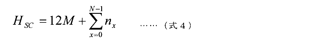
図9Aでは、HSCを超えない最大の素数で決定される系列長を有するCAZAC系列を用いて、図示される部分RBの左から4つ目のサブキャリアまでのRSが生成される。部分RBの残り2サブキャリアのRSには、当該CAZAC系列の巡回拡張が用いられる。
[実施形態7.2]
実施形態7.2では、完全RBのみの場合に用いるCAZAC系列(既存のDMRSのCAZAC系列)の巡回拡張を、部分RBのRSに用いる。当該系列の系列長NZC RSは、例えば、3、6、8、10など12未満の値であってもよいし、所定の値(MSC)を超えない最大の素数によって定義されてもよい。ここで、MSC=12Mであり、完全RBのみの総サブキャリア数に相当する。つまり、実施形態7.2のCAZAC系列の系列長は、部分RBを無視して完全RBのみを考慮した場合の、既存のCAZAC系列の系列長に相当する。
実施形態7.2では、完全RBのみの場合に用いるCAZAC系列(既存のDMRSのCAZAC系列)の巡回拡張を、部分RBのRSに用いる。当該系列の系列長NZC RSは、例えば、3、6、8、10など12未満の値であってもよいし、所定の値(MSC)を超えない最大の素数によって定義されてもよい。ここで、MSC=12Mであり、完全RBのみの総サブキャリア数に相当する。つまり、実施形態7.2のCAZAC系列の系列長は、部分RBを無視して完全RBのみを考慮した場合の、既存のCAZAC系列の系列長に相当する。
図9Bでは、MSCを超えない最大の素数で決定される系列長を有するCAZAC系列を用いて、図示される完全RBの左から8つ目のサブキャリアまでのRSが生成される。当該完全RBの残り4サブキャリア及び部分RBのサブキャリアのRSには、当該CAZAC系列の巡回拡張が用いられる。
[実施形態7.3]
実施形態7.3では、実施形態2.3で述べたように、部分RB用RSが定義されない。つまり、実施形態7.3では、部分RBには、RSはマッピングされず、RS以外の信号(データ信号、制御信号など)がマッピングされる。この場合、完全RBのみにRSをマッピングすればよく、部分RBのRSを考慮する必要がない。
実施形態7.3では、実施形態2.3で述べたように、部分RB用RSが定義されない。つまり、実施形態7.3では、部分RBには、RSはマッピングされず、RS以外の信号(データ信号、制御信号など)がマッピングされる。この場合、完全RBのみにRSをマッピングすればよく、部分RBのRSを考慮する必要がない。
実施形態7.3においては、UEは、部分RBが完全RBに隣接してスケジュールされると想定してもよい。完全RBにマッピングされるRSは、完全RBのみがスケジュールされたかのように、CAZAC系列から生成される。当該CAZAC系列は、既存のLTEにおけるCAZAC系列であってもよい。当該系列の系列長NZC
RSは、例えば、実施形態7.2で述べたMSCを超えない最大の素数によって定義されてもよい。
部分RBにおいて、完全RBだったとしたらRSがマッピングされていたリソースには、データ信号及び/又は制御信号がマッピングされてもよいし、信号がマッピングされなくてもよい。また、UEは、部分RBにおいて、完全RBだったとしたらRSがマッピングされていたリソースを無視してもよい(受信処理を行わなくてもよい)。
図9Cでは、MSCを超えない最大の素数で決定される系列長を有するCAZAC系列を用いて、図示される完全RBの左から8つ目のサブキャリアまでのRSが生成される。当該完全RBの残り4サブキャリアのRSには、当該CAZAC系列の巡回拡張が用いられる。また、部分RBには、RSがマッピングされない。
以上説明した第7の実施形態によれば、RSについて12未満の系列長が必要な場合に対応することができる。
<第8の実施形態>
第8の実施形態は、上りリンクにおける部分RBの電力制御に関する。
第8の実施形態は、上りリンクにおける部分RBの電力制御に関する。
既存のLTEにおいて、セルcのサブフレームiにおけるPUSCH(Physical Uplink Shared Channel)の送信電力PPUSCH,c(i)は、下記式5で表すことができる。

ここで、PCMAX,c(i)は、UEの最大送信電力である。MPUSCH,c(i)は、UEに割り当てられたPUSCH用の帯域幅(RB数)である。P0_PUSCH,c(j)は、目標受信電力(目標受信SNR:Signal to Noise Ratio)に係るパラメータ(送信電力オフセットに関するパラメータ)である。αc(j)は、フラクショナルTPCの重み係数である。PLcは、パスロス(伝搬損失)に相当する。ΔTF,c(i)は、PUSCHに適用されるMCSに基づくオフセット、fc(i)は、TPCコマンドによる補正値である。
なお、上記PCMAX,c(i)、MPUSCH,c(i)、P0_PUSCH,c(j)、αc(j)、PLc、ΔTF,c(i)、fc(i)は、それぞれ、c、i及びjの少なくとも1つを省いて表記されてもよい。また、これらの値は複数のセル及び/又は複数のサブフレームについて用いられてもよい。
式5は、RBが完全RBか部分RBかを区別していないため、部分RBが設定される場合の上り電力制御に利用することが好ましくないと想定される。そこで、本発明者らは、部分RBが設定される場合の上り電力制御を見出した。具体的には、第8の実施形態では、式5のMPUSCHを、部分RBを適切に考慮した帯域幅として新たに定義する。
UE及び/又は基地局は、部分RBを含むPUSCHについて、スケジュールされる部分RBのリソースを完全RB単位に換算したリソース数に基づいて、PUSCHの送信電力を判断する。例えば、MPUSCHを下記式6で定義してもよい。

ここで、Mはスケジュールされる完全RB数、Nはスケジュールされる部分RB数、nxはx番目のスケジュールされる部分RBが含むサブキャリア数である。
式6では、スケジュールされる周波数リソースに相当する帯域幅を、RB単位で切り上げている。これにより、スケジュールされるRBが完全RBか部分RBによらず、同じ送信電力を維持することができる。
また、MPUSCHを下記式7で定義してもよい。

式7では、スケジュールされる周波数リソースに相当する帯域幅を、RB単位で切り上げせずそのままとしている。これにより、スケジュールされるRBが完全RBか部分RBによらず、同じ電力密度(PSD:Power Spectrum Density)を維持することができる。
なお、ここでは上り共有チャネル(PUSCH)の送信電力について説明したが、他のチャネル/信号についても同様の制御を適用してもよい。例えば上り制御チャネル(PUCCH:Physical Uplink Shared Channel)、上り参照信号(例えば、SRS:Sounding Reference Signal)なども同様の方針で、部分RBに含まれるサブキャリア数を考慮した送信電力を制御することができる。
以上説明した第8の実施形態によれば、部分RBがスケジュールされる場合であっても、上り送信電力を適切に制御することができる。
<変形例>
各実施形態で説明した部分RBについての処理に関する情報は、仕様で予め規定されてもよいし、上位レイヤシグナリング(例えば、RRCシグナリング)、物理レイヤシグナリング(例えば、DCI)、その他の信号又はこれらの組み合わせによって、UEに通知(設定、指示)されてもよい。
各実施形態で説明した部分RBについての処理に関する情報は、仕様で予め規定されてもよいし、上位レイヤシグナリング(例えば、RRCシグナリング)、物理レイヤシグナリング(例えば、DCI)、その他の信号又はこれらの組み合わせによって、UEに通知(設定、指示)されてもよい。
例えば、部分RB(の領域)に関するパラメータ(第1の実施形態)、部分RB用RSのリソースマッピングパターンに関する情報(第2の実施形態)、データのマッピング方法を特定するための情報(第3の実施形態)、部分RB用RSの下り制御チャネル候補のリソースに関する情報(第5の実施形態)、部分RBで用いるCAZAC系列の系列長(第7の実施形態)などが通知されてもよい。UEは、通知された情報に基づいて部分RB及び/又は完全RBに関する制御を行ってもよい。
なお、各実施形態では、サブキャリア数が12未満の部分RBについて説明したが、本発明は他の構成のRBに適用されてもよい。例えば、サブキャリア数が12より大きいRB(例えば、スーパーRBと呼ばれてもよい)を用いる場合には、各実施形態の部分RBをスーパーRBで読み替えてもよい。また、各実施形態における「12」という定数は、別の値であってもよい。
(無線通信システム)
以下、本発明の一実施形態に係る無線通信システムの構成について説明する。この無線通信システムでは、本発明の上記各実施形態に係る無線通信方法のいずれか又はこれらの組み合わせを用いて通信が行われる。
以下、本発明の一実施形態に係る無線通信システムの構成について説明する。この無線通信システムでは、本発明の上記各実施形態に係る無線通信方法のいずれか又はこれらの組み合わせを用いて通信が行われる。
図10は、本発明の一実施形態に係る無線通信システムの概略構成の一例を示す図である。無線通信システム1では、LTEシステムのシステム帯域幅(例えば、20MHz)を1単位とする複数の基本周波数ブロック(コンポーネントキャリア)を一体としたキャリアアグリゲーション(CA)及び/又はデュアルコネクティビティ(DC)を適用することができる。
なお、無線通信システム1は、LTE(Long Term Evolution)、LTE-A(LTE-Advanced)、LTE-B(LTE-Beyond)、SUPER 3G、IMT-Advanced、4G(4th generation mobile communication system)、5G(5th generation mobile communication system)、FRA(Future Radio Access)、New-RAT(Radio Access Technology)などと呼ばれてもよいし、これらを実現するシステムと呼ばれてもよい。
無線通信システム1は、比較的カバレッジの広いマクロセルC1を形成する無線基地局11と、マクロセルC1内に配置され、マクロセルC1よりも狭いスモールセルC2を形成する無線基地局12(12a-12c)と、を備えている。また、マクロセルC1及び各スモールセルC2には、ユーザ端末20が配置されている。各セル及びユーザ端末20の配置は、図に示すものに限られない。
ユーザ端末20は、無線基地局11及び無線基地局12の双方に接続することができる。ユーザ端末20は、マクロセルC1及びスモールセルC2を、CA又はDCにより同時に使用することが想定される。また、ユーザ端末20は、複数のセル(CC)(例えば、5個以下のCC、6個以上のCC)を用いてCA又はDCを適用してもよい。
ユーザ端末20と無線基地局11との間は、相対的に低い周波数帯域(例えば、2GHz)で帯域幅が狭いキャリア(既存キャリア、legacy carrierなどとも呼ばれる)を用いて通信を行うことができる。一方、ユーザ端末20と無線基地局12との間は、相対的に高い周波数帯域(例えば、3.5GHz、5GHzなど)で帯域幅が広いキャリアが用いられてもよいし、無線基地局11との間と同じキャリアが用いられてもよい。なお、各無線基地局が利用する周波数帯域の構成はこれに限られない。
無線基地局11と無線基地局12との間(又は、2つの無線基地局12間)は、有線接続(例えば、CPRI(Common Public Radio Interface)に準拠した光ファイバ、X2インターフェースなど)又は無線接続する構成とすることができる。
無線基地局11及び各無線基地局12は、それぞれ上位局装置30に接続され、上位局装置30を介してコアネットワーク40に接続される。なお、上位局装置30には、例えば、アクセスゲートウェイ装置、無線ネットワークコントローラ(RNC)、モビリティマネジメントエンティティ(MME)などが含まれるが、これに限定されるものではない。また、各無線基地局12は、無線基地局11を介して上位局装置30に接続されてもよい。
なお、無線基地局11は、相対的に広いカバレッジを有する無線基地局であり、マクロ基地局、集約ノード、eNB(eNodeB)、送受信ポイント、などと呼ばれてもよい。また、無線基地局12は、局所的なカバレッジを有する無線基地局であり、スモール基地局、マイクロ基地局、ピコ基地局、フェムト基地局、HeNB(Home eNodeB)、RRH(Remote Radio Head)、送受信ポイントなどと呼ばれてもよい。以下、無線基地局11及び12を区別しない場合は、無線基地局10と総称する。
各ユーザ端末20は、LTE、LTE-Aなどの各種通信方式に対応した端末であり、移動通信端末(移動局)だけでなく固定通信端末(固定局)を含んでもよい。
無線通信システム1においては、無線アクセス方式として、下りリンクに直交周波数分割多元接続(OFDMA:Orthogonal Frequency Division Multiple Access)が適用され、上りリンクにシングルキャリア-周波数分割多元接続(SC-FDMA:Single Carrier Frequency Division Multiple Access)が適用される。
OFDMAは、周波数帯域を複数の狭い周波数帯域(サブキャリア)に分割し、各サブキャリアにデータをマッピングして通信を行うマルチキャリア伝送方式である。SC-FDMAは、システム帯域幅を端末毎に1つ又は連続したリソースブロックからなる帯域に分割し、複数の端末が互いに異なる帯域を用いることで、端末間の干渉を低減するシングルキャリア伝送方式である。なお、上り及び下りの無線アクセス方式は、これらの組み合わせに限らず、他の無線アクセス方式が用いられてもよい。
無線通信システム1では、下りリンクのチャネルとして、各ユーザ端末20で共有される下り共有チャネル(PDSCH:Physical Downlink Shared Channel)、ブロードキャストチャネル(PBCH:Physical Broadcast Channel)、下りL1/L2制御チャネルなどが用いられる。PDSCHにより、ユーザデータ、上位レイヤ制御情報、SIB(System Information Block)などが伝送される。また、PBCHにより、MIB(Master Information Block)が伝送される。
下りL1/L2制御チャネルは、PDCCH(Physical Downlink Control Channel)、EPDCCH(Enhanced Physical Downlink Control Channel)、PCFICH(Physical Control Format Indicator Channel)、PHICH(Physical Hybrid-ARQ Indicator Channel)などを含む。PDCCHにより、PDSCH及びPUSCHのスケジューリング情報を含む下り制御情報(DCI:Downlink Control Information)などが伝送される。PCFICHにより、PDCCHに用いるOFDMシンボル数が伝送される。PHICHにより、PUSCHに対するHARQ(Hybrid Automatic Repeat reQuest)の送達確認情報(例えば、再送制御情報、HARQ-ACK、ACK/NACKなどともいう)が伝送される。EPDCCHは、PDSCH(下り共有データチャネル)と周波数分割多重され、PDCCHと同様にDCIなどの伝送に用いられる。
無線通信システム1では、上りリンクのチャネルとして、各ユーザ端末20で共有される上り共有チャネル(PUSCH:Physical Uplink Shared Channel)、上り制御チャネル(PUCCH:Physical Uplink Control Channel)、ランダムアクセスチャネル(PRACH:Physical Random Access Channel)などが用いられる。PUSCHにより、ユーザデータ、上位レイヤ制御情報などが伝送される。また、PUCCHにより、下りリンクの無線品質情報(CQI:Channel Quality Indicator)、送達確認情報などが伝送される。PRACHにより、セルとの接続確立のためのランダムアクセスプリアンブルが伝送される。
無線通信システム1では、下り参照信号として、セル固有参照信号(CRS:Cell-specific Reference Signal)、チャネル状態情報参照信号(CSI-RS:Channel State Information-Reference Signal)、復調用参照信号(DMRS:DeModulation Reference Signal)、位置決定参照信号(PRS:Positioning Reference Signal)などが伝送される。また、無線通信システム1では、上り参照信号として、測定用参照信号(SRS:Sounding Reference Signal)、復調用参照信号(DMRS)などが伝送される。なお、DMRSはユーザ端末固有参照信号(UE-specific Reference Signal)と呼ばれてもよい。また、伝送される参照信号は、これらに限られない。
(無線基地局)
図11は、本発明の一実施形態に係る無線基地局の全体構成の一例を示す図である。無線基地局10は、複数の送受信アンテナ101と、アンプ部102と、送受信部103と、ベースバンド信号処理部104と、呼処理部105と、伝送路インターフェース106と、を備えている。なお、送受信アンテナ101、アンプ部102、送受信部103は、それぞれ1つ以上を含むように構成されればよい。
図11は、本発明の一実施形態に係る無線基地局の全体構成の一例を示す図である。無線基地局10は、複数の送受信アンテナ101と、アンプ部102と、送受信部103と、ベースバンド信号処理部104と、呼処理部105と、伝送路インターフェース106と、を備えている。なお、送受信アンテナ101、アンプ部102、送受信部103は、それぞれ1つ以上を含むように構成されればよい。
下りリンクにより無線基地局10からユーザ端末20に送信されるユーザデータは、上位局装置30から伝送路インターフェース106を介してベースバンド信号処理部104に入力される。
ベースバンド信号処理部104では、ユーザデータに関して、PDCP(Packet Data Convergence Protocol)レイヤの処理、ユーザデータの分割・結合、RLC(Radio Link Control)再送制御などのRLCレイヤの送信処理、MAC(Medium Access Control)再送制御(例えば、HARQの送信処理)、スケジューリング、伝送フォーマット選択、チャネル符号化、逆高速フーリエ変換(IFFT:Inverse Fast Fourier Transform)処理、プリコーディング処理などの送信処理が行われて送受信部103に転送される。また、下り制御信号に関しても、チャネル符号化、逆高速フーリエ変換などの送信処理が行われて、送受信部103に転送される。
送受信部103は、ベースバンド信号処理部104からアンテナ毎にプリコーディングして出力されたベースバンド信号を無線周波数帯に変換して送信する。送受信部103で周波数変換された無線周波数信号は、アンプ部102により増幅され、送受信アンテナ101から送信される。送受信部103は、本発明に係る技術分野での共通認識に基づいて説明されるトランスミッター/レシーバー、送受信回路又は送受信装置から構成することができる。なお、送受信部103は、一体の送受信部として構成されてもよいし、送信部及び受信部から構成されてもよい。
一方、上り信号については、送受信アンテナ101で受信された無線周波数信号がアンプ部102で増幅される。送受信部103はアンプ部102で増幅された上り信号を受信する。送受信部103は、受信信号をベースバンド信号に周波数変換して、ベースバンド信号処理部104に出力する。
ベースバンド信号処理部104では、入力された上り信号に含まれるユーザデータに対して、高速フーリエ変換(FFT:Fast Fourier Transform)処理、逆離散フーリエ変換(IDFT:Inverse Discrete Fourier Transform)処理、誤り訂正復号、MAC再送制御の受信処理、RLCレイヤ及びPDCPレイヤの受信処理がなされ、伝送路インターフェース106を介して上位局装置30に転送される。呼処理部105は、通信チャネルの呼処理(設定、解放など)、無線基地局10の状態管理、無線リソースの管理などを行う。
伝送路インターフェース106は、所定のインターフェースを介して、上位局装置30と信号を送受信する。また、伝送路インターフェース106は、基地局間インターフェース(例えば、CPRI(Common Public Radio Interface)に準拠した光ファイバ、X2インターフェース)を介して他の無線基地局10と信号を送受信(バックホールシグナリング)してもよい。
送受信部103は、所定の数(例えば、12)より少ないサブキャリアから成る部分RB(第1のリソース単位)に関する情報を送信してもよい。送受信部103は、部分RBに割り当てられる信号を送信及び/又は受信してもよい。
図12は、本発明の一実施形態に係る無線基地局の機能構成の一例を示す図である。なお、本例では、本実施形態における特徴部分の機能ブロックを主に示しており、無線基地局10は、無線通信に必要な他の機能ブロックも有しているものとする。
ベースバンド信号処理部104は、制御部(スケジューラ)301と、送信信号生成部302と、マッピング部303と、受信信号処理部304と、測定部305と、を少なくとも備えている。なお、これらの構成は、無線基地局10に含まれていればよく、一部又は全部の構成がベースバンド信号処理部104に含まれなくてもよい。
制御部(スケジューラ)301は、無線基地局10全体の制御を実施する。制御部301は、本発明に係る技術分野での共通認識に基づいて説明されるコントローラ、制御回路又は制御装置から構成することができる。
制御部301は、例えば、送信信号生成部302による信号の生成、マッピング部303による信号の割り当てなどを制御する。また、制御部301は、受信信号処理部304による信号の受信処理、測定部305による信号の測定などを制御する。
制御部301は、システム情報、下りデータ信号(例えば、PDSCHで送信される信号)、下り制御信号(例えば、PDCCH及び/又はEPDCCHで伝送される信号)のスケジューリング(例えば、リソース割り当て)を制御する。また、制御部301は、上りデータ信号に対する再送制御の要否を判定した結果などに基づいて、下り制御信号(例えば、送達確認情報など)、下りデータ信号などの生成を制御する。また、制御部301は、同期信号(例えば、PSS(Primary Synchronization Signal)/SSS(Secondary Synchronization Signal))、下り参照信号(例えば、CRS、CSI-RS、DMRS)などのスケジューリングの制御を行う。
また、制御部301は、上りデータ信号(例えば、PUSCHで送信される信号)、上り制御信号(例えば、PUCCH及び/又はPUSCHで送信される信号)、PRACHで送信されるランダムアクセスプリアンブル、上り参照信号などのスケジューリングを制御する。
制御部301は、所定の数(例えば、12)より少ないサブキャリアから成る部分RB(第1のリソース単位)を用いてスケジューリングを行ってもよい。また、制御部301は、部分RBに関する情報をユーザ端末20に送信する制御を行ってもよい。制御部301は、上記所定の数と同じ数のサブキャリアから成る完全RB(第2のリソース単位)の周波数領域を特定し、当該周波数領域内での部分RBを用いる通信を制御してもよい。
制御部301は、部分RBで用いる参照信号を、完全RBで用いる参照信号のためのリソースマッピング規則と異なるリソースマッピング規則に従ってマッピングする制御を行ってもよい。制御部301は、部分RB及び完全RBの両方についてデータがスケジュールされる場合、部分RBのリソースより優先して完全RBのリソースにデータをマッピングしてもよい。
制御部301は、部分RBについてデータがスケジュールされる場合、スケジュールされる部分RBのリソースを完全RBに換算したリソース数に基づいて、データのトランスポートブロックサイズ及び/又は送信電力を判断してもよい。
制御部301は、部分RBに属する領域では下り制御チャネルを送信しないように制御してもよい。制御部301は、上りリンクでは、部分RBを用いる通信が所定の無線アクセス方式に限定されると想定して制御を行ってもよい。制御部301は、部分RB用の参照信号系列として、完全RB用の参照信号系列より短い又は長い系列を用いてもよい。
送信信号生成部302は、制御部301からの指示に基づいて、下り信号(下り制御信号、下りデータ信号、下り参照信号など)を生成して、マッピング部303に出力する。送信信号生成部302は、本発明に係る技術分野での共通認識に基づいて説明される信号生成器、信号生成回路又は信号生成装置から構成することができる。
送信信号生成部302は、例えば、制御部301からの指示に基づいて、下り信号の割り当て情報を通知するDLアサインメント及び上り信号の割り当て情報を通知するULグラントを生成する。また、下りデータ信号には、各ユーザ端末20からのチャネル状態情報(CSI:Channel State Information)などに基づいて決定された符号化率、変調方式などに従って符号化処理、変調処理が行われる。
マッピング部303は、制御部301からの指示に基づいて、送信信号生成部302で生成された下り信号を、所定の無線リソースにマッピングして、送受信部103に出力する。マッピング部303は、本発明に係る技術分野での共通認識に基づいて説明されるマッパー、マッピング回路又はマッピング装置から構成することができる。
受信信号処理部304は、送受信部103から入力された受信信号に対して、受信処理(例えば、デマッピング、復調、復号など)を行う。ここで、受信信号は、例えば、ユーザ端末20から送信される上り信号(上り制御信号、上りデータ信号、上り参照信号など)である。受信信号処理部304は、本発明に係る技術分野での共通認識に基づいて説明される信号処理器、信号処理回路又は信号処理装置から構成することができる。
受信信号処理部304は、受信処理により復号された情報を制御部301に出力する。例えば、HARQ-ACKを含むPUCCHを受信した場合、HARQ-ACKを制御部301に出力する。また、受信信号処理部304は、受信信号及び/又は受信処理後の信号を、測定部305に出力する。
測定部305は、受信した信号に関する測定を実施する。測定部305は、本発明に係る技術分野での共通認識に基づいて説明される測定器、測定回路又は測定装置から構成することができる。
例えば、測定部305は、受信した信号に基づいて、RRM(Radio Resource Management)測定、CSI(Channel State Information)測定などを行ってもよい。測定部305は、受信電力(例えば、RSRP(Reference Signal Received Power))、受信品質(例えば、RSRQ(Reference Signal Received Quality)、SINR(Signal to Interference plus Noise Ratio))、電力強度(例えば、RSSI(Received Signal Strength Indicator))、上り伝搬路情報(例えば、CSI)などについて測定してもよい。測定結果は、制御部301に出力されてもよい。
(ユーザ端末)
図13は、本発明の一実施形態に係るユーザ端末の全体構成の一例を示す図である。ユーザ端末20は、複数の送受信アンテナ201と、アンプ部202と、送受信部203と、ベースバンド信号処理部204と、アプリケーション部205と、を備えている。なお、送受信アンテナ201、アンプ部202、送受信部203は、それぞれ1つ以上を含むように構成されればよい。
図13は、本発明の一実施形態に係るユーザ端末の全体構成の一例を示す図である。ユーザ端末20は、複数の送受信アンテナ201と、アンプ部202と、送受信部203と、ベースバンド信号処理部204と、アプリケーション部205と、を備えている。なお、送受信アンテナ201、アンプ部202、送受信部203は、それぞれ1つ以上を含むように構成されればよい。
送受信アンテナ201で受信された無線周波数信号は、アンプ部202で増幅される。送受信部203は、アンプ部202で増幅された下り信号を受信する。送受信部203は、受信信号をベースバンド信号に周波数変換して、ベースバンド信号処理部204に出力する。送受信部203は、本発明に係る技術分野での共通認識に基づいて説明されるトランスミッター/レシーバー、送受信回路又は送受信装置から構成することができる。なお、送受信部203は、一体の送受信部として構成されてもよいし、送信部及び受信部から構成されてもよい。
ベースバンド信号処理部204は、入力されたベースバンド信号に対して、FFT処理、誤り訂正復号、再送制御の受信処理などを行う。下りリンクのユーザデータは、アプリケーション部205に転送される。アプリケーション部205は、物理レイヤ及びMACレイヤより上位のレイヤに関する処理などを行う。また、下りリンクのデータのうち、ブロードキャスト情報もアプリケーション部205に転送されてもよい。
一方、上りリンクのユーザデータについては、アプリケーション部205からベースバンド信号処理部204に入力される。ベースバンド信号処理部204では、再送制御の送信処理(例えば、HARQの送信処理)、チャネル符号化、プリコーディング、離散フーリエ変換(DFT:Discrete Fourier Transform)処理、IFFT処理などが行われて送受信部203に転送される。送受信部203は、ベースバンド信号処理部204から出力されたベースバンド信号を無線周波数帯に変換して送信する。送受信部203で周波数変換された無線周波数信号は、アンプ部202により増幅され、送受信アンテナ201から送信される。
送受信部203は、所定の数(例えば、12)より少ないサブキャリアから成る部分RB(第1のリソース単位)に関する情報を受信してもよい。送受信部203は、部分RBに割り当てられる信号を送信及び/又は受信してもよい。
図14は、本発明の一実施形態に係るユーザ端末の機能構成の一例を示す図である。なお、本例においては、本実施形態における特徴部分の機能ブロックを主に示しており、ユーザ端末20は、無線通信に必要な他の機能ブロックも有しているものとする。
ユーザ端末20が有するベースバンド信号処理部204は、制御部401と、送信信号生成部402と、マッピング部403と、受信信号処理部404と、測定部405と、を少なくとも備えている。なお、これらの構成は、ユーザ端末20に含まれていればよく、一部又は全部の構成がベースバンド信号処理部204に含まれなくてもよい。
制御部401は、ユーザ端末20全体の制御を実施する。制御部401は、本発明に係る技術分野での共通認識に基づいて説明されるコントローラ、制御回路又は制御装置から構成することができる。
制御部401は、例えば、送信信号生成部402による信号の生成、マッピング部403による信号の割り当てなどを制御する。また、制御部401は、受信信号処理部404による信号の受信処理、測定部405による信号の測定などを制御する。
制御部401は、無線基地局10から送信された下り制御信号(例えば、PDCCH/EPDCCHで送信された信号)及び下りデータ信号(例えば、PDSCHで送信された信号)を、受信信号処理部404から取得する。制御部401は、下り制御信号及び/又は下りデータ信号に対する再送制御の要否を判定した結果などに基づいて、上り制御信号(例えば、送達確認情報など)及び/又は上りデータ信号の生成を制御する。
制御部401は、所定の数(例えば、12)より少ないサブキャリアから成る部分RB(第1のリソース単位)に関する情報に基づいて、当該所定の数と同じ数のサブキャリアから成る完全RB(第2のリソース単位)の周波数領域を特定し、当該周波数領域内での部分RBを用いる通信を制御する。ここで、部分RBを構成するサブキャリアは、非連続なサブキャリアを含んでもよい。
制御部401は、部分RBで用いる参照信号を、完全RBで用いる参照信号のためのリソースマッピング規則と異なるリソースマッピング規則に従ってマッピングする制御を行ってもよい。制御部401は、部分RB及び完全RBの両方についてデータがスケジュールされる場合、部分RBのリソースより優先して完全RBのリソースにデータをマッピングしてもよい。
制御部401は、部分RBについてデータがスケジュールされる場合、スケジュールされる部分RBのリソースを完全RBに換算したリソース数に基づいて、データのトランスポートブロックサイズ及び/又は送信電力を判断してもよい。
制御部401は、部分RBに属する領域では下り制御チャネル候補をモニタしないように制御してもよい。制御部401は、上りリンクでは、部分RBを用いる通信が所定の無線アクセス方式に限定されると想定して制御を行ってもよい。制御部401は、部分RB用の参照信号系列として、完全RB用の参照信号系列より短い又は長い系列を用いてもよい。
また、制御部401は、無線基地局10から通知された各種情報を受信信号処理部404から取得した場合、当該情報に基づいて制御に用いるパラメータを更新してもよい。
送信信号生成部402は、制御部401からの指示に基づいて、上り信号(上り制御信号、上りデータ信号、上り参照信号など)を生成して、マッピング部403に出力する。送信信号生成部402は、本発明に係る技術分野での共通認識に基づいて説明される信号生成器、信号生成回路又は信号生成装置から構成することができる。
送信信号生成部402は、例えば、制御部401からの指示に基づいて、送達確認情報、チャネル状態情報(CSI)などに関する上り制御信号を生成する。また、送信信号生成部402は、制御部401からの指示に基づいて上りデータ信号を生成する。例えば、送信信号生成部402は、無線基地局10から通知される下り制御信号にULグラントが含まれている場合に、制御部401から上りデータ信号の生成を指示される。
マッピング部403は、制御部401からの指示に基づいて、送信信号生成部402で生成された上り信号を無線リソースにマッピングして、送受信部203へ出力する。マッピング部403は、本発明に係る技術分野での共通認識に基づいて説明されるマッパー、マッピング回路又はマッピング装置から構成することができる。
受信信号処理部404は、送受信部203から入力された受信信号に対して、受信処理(例えば、デマッピング、復調、復号など)を行う。ここで、受信信号は、例えば、無線基地局10から送信される下り信号(下り制御信号、下りデータ信号、下り参照信号など)である。受信信号処理部404は、本発明に係る技術分野での共通認識に基づいて説明される信号処理器、信号処理回路又は信号処理装置から構成することができる。また、受信信号処理部404は、本発明に係る受信部を構成することができる。
受信信号処理部404は、受信処理により復号された情報を制御部401に出力する。受信信号処理部404は、例えば、ブロードキャスト情報、システム情報、RRCシグナリング、DCIなどを、制御部401に出力する。また、受信信号処理部404は、受信信号及び/又は受信処理後の信号を、測定部405に出力する。
測定部405は、受信した信号に関する測定を実施する。例えば、測定部405は、無線基地局10から送信された下り参照信号を用いて測定を実施する。測定部405は、本発明に係る技術分野での共通認識に基づいて説明される測定器、測定回路又は測定装置から構成することができる。
例えば、測定部405は、受信した信号に基づいて、RRM測定、CSI測定などを行ってもよい。測定部405は、受信電力(例えば、RSRP)、受信品質(例えば、RSRQ、SINR)、電力強度(例えば、RSSI)、下り伝搬路情報(例えば、CSI)などについて測定してもよい。測定結果は、制御部401に出力されてもよい。
(ハードウェア構成)
なお、上記実施形態の説明に用いたブロック図は、機能単位のブロックを示している。これらの機能ブロック(構成部)は、ハードウェア及び/又はソフトウェアの任意の組み合わせによって実現される。また、各機能ブロックの実現手段は特に限定されない。すなわち、各機能ブロックは、物理的及び/又は論理的に結合した1つの装置により実現されてもよいし、物理的及び/又は論理的に分離した2つ以上の装置を直接的及び/又は間接的に(例えば、有線及び/又は無線)で接続し、これら複数の装置により実現されてもよい。
なお、上記実施形態の説明に用いたブロック図は、機能単位のブロックを示している。これらの機能ブロック(構成部)は、ハードウェア及び/又はソフトウェアの任意の組み合わせによって実現される。また、各機能ブロックの実現手段は特に限定されない。すなわち、各機能ブロックは、物理的及び/又は論理的に結合した1つの装置により実現されてもよいし、物理的及び/又は論理的に分離した2つ以上の装置を直接的及び/又は間接的に(例えば、有線及び/又は無線)で接続し、これら複数の装置により実現されてもよい。
例えば、本発明の一実施形態における無線基地局、ユーザ端末などは、本発明の無線通信方法の処理を行うコンピュータとして機能してもよい。図15は、本発明の一実施形態に係る無線基地局及びユーザ端末のハードウェア構成の一例を示す図である。上述の無線基地局10及びユーザ端末20は、物理的には、プロセッサ1001、メモリ1002、ストレージ1003、通信装置1004、入力装置1005、出力装置1006、バス1007などを含むコンピュータ装置として構成されてもよい。
なお、以下の説明では、「装置」という文言は、回路、デバイス、ユニットなどに読み替えることができる。無線基地局10及びユーザ端末20のハードウェア構成は、図に示した各装置を1つ又は複数含むように構成されてもよいし、一部の装置を含まずに構成されてもよい。
例えば、プロセッサ1001は1つだけ図示されているが、複数のプロセッサがあってもよい。また、処理は、1のプロセッサで実行されてもよいし、処理が同時に、逐次に、又はその他の手法で、1以上のプロセッサで実行されてもよい。なお、プロセッサ1001は、1以上のチップで実装されてもよい。
無線基地局10及びユーザ端末20における各機能は、例えば、プロセッサ1001、メモリ1002などのハードウェア上に所定のソフトウェア(プログラム)を読み込ませることで、プロセッサ1001が演算を行い、通信装置1004による通信を制御したり、メモリ1002及びストレージ1003におけるデータの読み出し及び/又は書き込みを制御したりすることで実現される。
プロセッサ1001は、例えば、オペレーティングシステムを動作させてコンピュータ全体を制御する。プロセッサ1001は、周辺装置とのインターフェース、制御装置、演算装置、レジスタなどを含む中央処理装置(CPU:Central Processing Unit)で構成されてもよい。例えば、上述のベースバンド信号処理部104(204)、呼処理部105などは、プロセッサ1001で実現されてもよい。
また、プロセッサ1001は、プログラム(プログラムコード)、ソフトウェアモジュール、データなどを、ストレージ1003及び/又は通信装置1004からメモリ1002に読み出し、これらに従って各種の処理を実行する。プログラムとしては、上述の実施形態で説明した動作の少なくとも一部をコンピュータに実行させるプログラムが用いられる。例えば、ユーザ端末20の制御部401は、メモリ1002に格納され、プロセッサ1001で動作する制御プログラムによって実現されてもよく、他の機能ブロックについても同様に実現されてもよい。
メモリ1002は、コンピュータ読み取り可能な記録媒体であり、例えば、ROM(Read Only Memory)、EPROM(Erasable Programmable ROM)、EEPROM(Electrically EPROM)、RAM(Random Access Memory)、その他の適切な記憶媒体の少なくとも1つで構成されてもよい。メモリ1002は、レジスタ、キャッシュ、メインメモリ(主記憶装置)などと呼ばれてもよい。メモリ1002は、本発明の一実施形態に係る無線通信方法を実施するために実行可能なプログラム(プログラムコード)、ソフトウェアモジュールなどを保存することができる。
ストレージ1003は、コンピュータ読み取り可能な記録媒体であり、例えば、フレキシブルディスク、フロッピー(登録商標)ディスク、光磁気ディスク(例えば、コンパクトディスク(CD-ROM(Compact Disc ROM)など)、デジタル多用途ディスク、Blu-ray(登録商標)ディスク)、リムーバブルディスク、ハードディスクドライブ、スマートカード、フラッシュメモリデバイス(例えば、カード、スティック、キードライブ)、磁気ストライプ、データベース、サーバ、その他の適切な記憶媒体の少なくとも1つで構成されてもよい。ストレージ1003は、補助記憶装置と呼ばれてもよい。
通信装置1004は、有線及び/又は無線ネットワークを介してコンピュータ間の通信を行うためのハードウェア(送受信デバイス)であり、例えばネットワークデバイス、ネットワークコントローラ、ネットワークカード、通信モジュールなどともいう。通信装置1004は、例えば周波数分割複信(FDD:Frequency Division Duplex)及び/又は時分割複信(TDD:Time Division Duplex)を実現するために、高周波スイッチ、デュプレクサ、フィルタ、周波数シンセサイザなどを含んで構成されてもよい。例えば、上述の送受信アンテナ101(201)、アンプ部102(202)、送受信部103(203)、伝送路インターフェース106などは、通信装置1004で実現されてもよい。
入力装置1005は、外部からの入力を受け付ける入力デバイス(例えば、キーボード、マウス、マイクロフォン、スイッチ、ボタン、センサなど)である。出力装置1006は、外部への出力を実施する出力デバイス(例えば、ディスプレイ、スピーカー、LED(Light Emitting Diode)ランプなど)である。なお、入力装置1005及び出力装置1006は、一体となった構成(例えば、タッチパネル)であってもよい。
また、プロセッサ1001、メモリ1002などの各装置は、情報を通信するためのバス1007で接続される。バス1007は、単一のバスで構成されてもよいし、装置間で異なるバスで構成されてもよい。
また、無線基地局10及びユーザ端末20は、マイクロプロセッサ、デジタル信号プロセッサ(DSP:Digital Signal Processor)、ASIC(Application Specific Integrated Circuit)、PLD(Programmable Logic Device)、FPGA(Field Programmable Gate Array)などのハードウェアを含んで構成されてもよく、当該ハードウェアにより、各機能ブロックの一部又は全てが実現されてもよい。例えば、プロセッサ1001は、これらのハードウェアの少なくとも1つで実装されてもよい。
(変形例)
なお、本明細書で説明した用語及び/又は本明細書の理解に必要な用語については、同一の又は類似する意味を有する用語と置き換えてもよい。例えば、チャネル及び/又はシンボルは信号(シグナリング)であってもよい。また、信号はメッセージであってもよい。参照信号は、RS(Reference Signal)と略称することもでき、適用される標準によってパイロット(Pilot)、パイロット信号などと呼ばれてもよい。また、コンポーネントキャリア(CC:Component Carrier)は、セル、周波数キャリア、キャリア周波数などと呼ばれてもよい。
なお、本明細書で説明した用語及び/又は本明細書の理解に必要な用語については、同一の又は類似する意味を有する用語と置き換えてもよい。例えば、チャネル及び/又はシンボルは信号(シグナリング)であってもよい。また、信号はメッセージであってもよい。参照信号は、RS(Reference Signal)と略称することもでき、適用される標準によってパイロット(Pilot)、パイロット信号などと呼ばれてもよい。また、コンポーネントキャリア(CC:Component Carrier)は、セル、周波数キャリア、キャリア周波数などと呼ばれてもよい。
また、無線フレームは、時間領域において1つ又は複数の期間(フレーム)で構成されてもよい。無線フレームを構成する当該1つ又は複数の各期間(フレーム)は、サブフレームと呼ばれてもよい。さらに、サブフレームは、時間領域において1つ又は複数のスロットで構成されてもよい。サブフレームは、ニューメロロジーに依存しない固定の時間長(例えば、1ms)であってもよい。
さらに、スロットは、時間領域において1つ又は複数のシンボル(OFDM(Orthogonal Frequency Division Multiplexing)シンボル、SC-FDMA(Single Carrier Frequency Division Multiple Access)シンボルなど)で構成されてもよい。また、スロットは、ニューメロロジーに基づく時間単位であってもよい。また、スロットは、ニューメロロジーに基づく時間単位であってもよい複数のミニスロットを含んでもよい。各ミニスロットは、時間領域において1つ又は複数のシンボルで構成されてもよい。
無線フレーム、サブフレーム、スロット、ミニスロット及びシンボルは、いずれも信号を伝送する際の時間単位を表す。無線フレーム、サブフレーム、スロット、ミニスロット及びシンボルは、それぞれに対応する別の呼称が用いられてもよい。例えば、1サブフレームは送信時間間隔(TTI:Transmission Time Interval)と呼ばれてもよいし、複数の連続したサブフレームがTTIと呼ばれてよいし、1スロット又は1ミニスロットがTTIと呼ばれてもよい。つまり、サブフレーム及び/又はTTIは、既存のLTEにおけるサブフレーム(1ms)であってもよいし、1msより短い期間(例えば、1-13シンボル)であってもよいし、1msより長い期間であってもよい。なお、TTIを表す単位は、サブフレームではなくスロット、ミニスロットなどと呼ばれてもよい。
ここで、TTIは、例えば、無線通信におけるスケジューリングの最小時間単位のことをいう。例えば、LTEシステムでは、無線基地局が各ユーザ端末に対して、無線リソース(各ユーザ端末において使用することが可能な周波数帯域幅、送信電力など)を、TTI単位で割り当てるスケジューリングを行う。なお、TTIの定義はこれに限られない。
TTIは、チャネル符号化されたデータパケット(トランスポートブロック)、コードブロック、及び/又はコードワードの送信時間単位であってもよいし、スケジューリング、リンクアダプテーションなどの処理単位となってもよい。なお、TTIが与えられたとき、実際にトランスポートブロック、コードブロック、及び/又はコードワードがマッピングされる時間区間(例えば、シンボル数)は、当該TTIよりも短くてもよい。
なお、1スロット又は1ミニスロットがTTIと呼ばれる場合、1以上のTTI(すなわち、1以上のスロット又は1以上のミニスロット)が、スケジューリングの最小時間単位となってもよい。また、当該スケジューリングの最小時間単位を構成するスロット数(ミニスロット数)は制御されてもよい。
1msの時間長を有するTTIは、通常TTI(LTE Rel.8-12におけるTTI)、ノーマルTTI、ロングTTI、通常サブフレーム、ノーマルサブフレーム、又はロングサブフレームなどと呼ばれてもよい。通常TTIより短いTTIは、短縮TTI、ショートTTI、部分TTI(partial又はfractional TTI)、短縮サブフレーム、又はショートサブフレームなどと呼ばれてもよい。
なお、ロングTTI(例えば、通常TTI、サブフレームなど)は、1msを超える時間長を有するTTIで読み替えてもよいし、ショートTTI(例えば、短縮TTIなど)は、ロングTTIのTTI長未満かつ1ms以上のTTI長を有するTTIで読み替えてもよい。
リソースブロック(RB:Resource Block)は、時間領域及び周波数領域のリソース割当単位であり、周波数領域において、1つ又は複数個の連続した副搬送波(サブキャリア(subcarrier))を含んでもよい。また、RBは、時間領域において、1つ又は複数個のシンボルを含んでもよく、1スロット、1ミニスロット、1サブフレーム又は1TTIの長さであってもよい。1TTI、1サブフレームは、それぞれ1つ又は複数のリソースブロックで構成されてもよい。なお、1つ又は複数のRBは、物理リソースブロック(PRB:Physical RB)、サブキャリアグループ(SCG:Sub-Carrier Group)、リソースエレメントグループ(REG:Resource Element Group)、PRBペア、RBペアなどと呼ばれてもよい。
また、リソースブロックは、1つ又は複数のリソースエレメント(RE:Resource Element)で構成されてもよい。例えば、1REは、1サブキャリア及び1シンボルの無線リソース領域であってもよい。
なお、上述した無線フレーム、サブフレーム、スロット、ミニスロット及びシンボルなどの構造は例示に過ぎない。例えば、無線フレームに含まれるサブフレームの数、サブフレーム又は無線フレームあたりのスロットの数、スロット内に含まれるミニスロットの数、スロット又はミニスロットに含まれるシンボル及びRBの数、RBに含まれるサブキャリアの数、並びにTTI内のシンボル数、シンボル長、サイクリックプレフィックス(CP:Cyclic Prefix)長などの構成は、様々に変更することができる。
また、本明細書で説明した情報、パラメータなどは、絶対値で表されてもよいし、所定の値からの相対値で表されてもよいし、対応する別の情報で表されてもよい。例えば、無線リソースは、所定のインデックスで指示されるものであってもよい。さらに、これらのパラメータを使用する数式などは、本明細書で明示的に開示したものと異なってもよい。
本明細書においてパラメータなどに使用する名称は、いかなる点においても限定的なものではない。例えば、様々なチャネル(PUCCH(Physical Uplink Control Channel)、PDCCH(Physical Downlink Control Channel)など)及び情報要素は、あらゆる好適な名称によって識別できるので、これらの様々なチャネル及び情報要素に割り当てている様々な名称は、いかなる点においても限定的なものではない。
本明細書で説明した情報、信号などは、様々な異なる技術のいずれかを使用して表されてもよい。例えば、上記の説明全体に渡って言及され得るデータ、命令、コマンド、情報、信号、ビット、シンボル、チップなどは、電圧、電流、電磁波、磁界若しくは磁性粒子、光場若しくは光子、又はこれらの任意の組み合わせによって表されてもよい。
また、情報、信号などは、上位レイヤから下位レイヤ、及び/又は下位レイヤから上位レイヤへ出力され得る。情報、信号などは、複数のネットワークノードを介して入出力されてもよい。
入出力された情報、信号などは、特定の場所(例えば、メモリ)に保存されてもよいし、管理テーブルで管理してもよい。入出力される情報、信号などは、上書き、更新又は追記をされ得る。出力された情報、信号などは、削除されてもよい。入力された情報、信号などは、他の装置へ送信されてもよい。
情報の通知は、本明細書で説明した態様/実施形態に限られず、他の方法で行われてもよい。例えば、情報の通知は、物理レイヤシグナリング(例えば、下り制御情報(DCI:Downlink Control Information)、上り制御情報(UCI:Uplink Control Information))、上位レイヤシグナリング(例えば、RRC(Radio Resource Control)シグナリング、ブロードキャスト情報(マスタ情報ブロック(MIB:Master Information Block)、システム情報ブロック(SIB:System Information Block)など)、MAC(Medium Access Control)シグナリング)、その他の信号又はこれらの組み合わせによって実施されてもよい。
なお、物理レイヤシグナリングは、L1/L2(Layer 1/Layer 2)制御情報(L1/L2制御信号)、L1制御情報(L1制御信号)などと呼ばれてもよい。また、RRCシグナリングは、RRCメッセージと呼ばれてもよく、例えば、RRC接続セットアップ(RRCConnectionSetup)メッセージ、RRC接続再構成(RRCConnectionReconfiguration)メッセージなどであってもよい。また、MACシグナリングは、例えば、MAC制御要素(MAC CE(Control Element))で通知されてもよい。
また、所定の情報の通知(例えば、「Xであること」の通知)は、明示的に行うものに限られず、暗示的に(例えば、当該所定の情報の通知を行わないことによって又は別の情報の通知によって)行われてもよい。
判定は、1ビットで表される値(0か1か)によって行われてもよいし、真(true)又は偽(false)で表される真偽値(boolean)によって行われてもよいし、数値の比較(例えば、所定の値との比較)によって行われてもよい。
ソフトウェアは、ソフトウェア、ファームウェア、ミドルウェア、マイクロコード、ハードウェア記述言語と呼ばれるか、他の名称で呼ばれるかを問わず、命令、命令セット、コード、コードセグメント、プログラムコード、プログラム、サブプログラム、ソフトウェアモジュール、アプリケーション、ソフトウェアアプリケーション、ソフトウェアパッケージ、ルーチン、サブルーチン、オブジェクト、実行可能ファイル、実行スレッド、手順、機能などを意味するよう広く解釈されるべきである。
また、ソフトウェア、命令、情報などは、伝送媒体を介して送受信されてもよい。例えば、ソフトウェアが、有線技術(同軸ケーブル、光ファイバケーブル、ツイストペア、デジタル加入者回線(DSL:Digital Subscriber Line)など)及び/又は無線技術(赤外線、マイクロ波など)を使用してウェブサイト、サーバ、又は他のリモートソースから送信される場合、これらの有線技術及び/又は無線技術は、伝送媒体の定義内に含まれる。
本明細書で使用する「システム」及び「ネットワーク」という用語は、互換的に使用される。
本明細書では、「基地局(BS:Base Station)」、「無線基地局」、「eNB」、「gNB」、「セル」、「セクタ」、「セルグループ」、「キャリア」及び「コンポーネントキャリア」という用語は、互換的に使用され得る。基地局は、固定局(fixed station)、NodeB、eNodeB(eNB)、アクセスポイント(access point)、送信ポイント、受信ポイント、フェムトセル、スモールセルなどの用語で呼ばれる場合もある。
基地局は、1つ又は複数(例えば、3つ)のセル(セクタとも呼ばれる)を収容することができる。基地局が複数のセルを収容する場合、基地局のカバレッジエリア全体は複数のより小さいエリアに区分でき、各々のより小さいエリアは、基地局サブシステム(例えば、屋内用の小型基地局(RRH:Remote Radio Head)によって通信サービスを提供することもできる。「セル」又は「セクタ」という用語は、このカバレッジにおいて通信サービスを行う基地局及び/又は基地局サブシステムのカバレッジエリアの一部又は全体を指す。
本明細書では、「移動局(MS:Mobile Station)」、「ユーザ端末(user terminal)」、「ユーザ装置(UE:User Equipment)」及び「端末」という用語は、互換的に使用され得る。基地局は、固定局(fixed station)、NodeB、eNodeB(eNB)、アクセスポイント(access point)、送信ポイント、受信ポイント、フェムトセル、スモールセルなどの用語で呼ばれる場合もある。
移動局は、当業者によって、加入者局、モバイルユニット、加入者ユニット、ワイヤレスユニット、リモートユニット、モバイルデバイス、ワイヤレスデバイス、ワイヤレス通信デバイス、リモートデバイス、モバイル加入者局、アクセス端末、モバイル端末、ワイヤレス端末、リモート端末、ハンドセット、ユーザエージェント、モバイルクライアント、クライアント又はいくつかの他の適切な用語で呼ばれる場合もある。
また、本明細書における無線基地局は、ユーザ端末で読み替えてもよい。例えば、無線基地局及びユーザ端末間の通信を、複数のユーザ端末間(D2D:Device-to-Device)の通信に置き換えた構成について、本発明の各態様/実施形態を適用してもよい。この場合、上述の無線基地局10が有する機能をユーザ端末20が有する構成としてもよい。また、「上り」及び「下り」などの文言は、「サイド」と読み替えられてもよい。例えば、上りチャネルは、サイドチャネルと読み替えられてもよい。
同様に、本明細書におけるユーザ端末は、無線基地局で読み替えてもよい。この場合、上述のユーザ端末20が有する機能を無線基地局10が有する構成としてもよい。
本明細書において、基地局によって行われるとした特定動作は、場合によってはその上位ノード(upper node)によって行われることもある。基地局を有する1つ又は複数のネットワークノード(network nodes)から成るネットワークにおいて、端末との通信のために行われる様々な動作は、基地局、基地局以外の1つ以上のネットワークノード(例えば、MME(Mobility Management Entity)、S-GW(Serving-Gateway)などが考えられるが、これらに限られない)又はこれらの組み合わせによって行われ得ることは明らかである。
本明細書で説明した各態様/実施形態は単独で用いてもよいし、組み合わせて用いてもよいし、実行に伴って切り替えて用いてもよい。また、本明細書で説明した各態様/実施形態の処理手順、シーケンス、フローチャートなどは、矛盾の無い限り、順序を入れ替えてもよい。例えば、本明細書で説明した方法については、例示的な順序で様々なステップの要素を提示しており、提示した特定の順序に限定されない。
本明細書で説明した各態様/実施形態は、LTE(Long Term Evolution)、LTE-A(LTE-Advanced)、LTE-B(LTE-Beyond)、SUPER 3G、IMT-Advanced、4G(4th generation mobile communication system)、5G(5th generation mobile communication system)、FRA(Future Radio Access)、New-RAT(Radio Access Technology)、NR(New Radio)、NX(New radio access)、FX(Future generation radio access)、GSM(登録商標)(Global System for Mobile communications)、CDMA2000、UMB(Ultra Mobile Broadband)、IEEE 802.11(Wi-Fi(登録商標))、IEEE 802.16(WiMAX(登録商標))、IEEE 802.20、UWB(Ultra-WideBand)、Bluetooth(登録商標)、その他の適切な無線通信方法を利用するシステム及び/又はこれらに基づいて拡張された次世代システムに適用されてもよい。
本明細書で使用する「に基づいて」という記載は、別段に明記されていない限り、「のみに基づいて」を意味しない。言い換えれば、「に基づいて」という記載は、「のみに基づいて」と「に少なくとも基づいて」の両方を意味する。
本明細書で使用する「第1の」、「第2の」などの呼称を使用した要素へのいかなる参照も、それらの要素の量又は順序を全般的に限定するものではない。これらの呼称は、2つ以上の要素間を区別する便利な方法として本明細書で使用され得る。したがって、第1及び第2の要素の参照は、2つの要素のみが採用され得ること又は何らかの形で第1の要素が第2の要素に先行しなければならないことを意味しない。
本明細書で使用する「判断(決定)(determining)」という用語は、多種多様な動作を包含する場合がある。例えば、「判断(決定)」は、計算(calculating)、算出(computing)、処理(processing)、導出(deriving)、調査(investigating)、探索(looking up)(例えば、テーブル、データベース又は別のデータ構造での探索)、確認(ascertaining)などを「判断(決定)」することであるとみなされてもよい。また、「判断(決定)」は、受信(receiving)(例えば、情報を受信すること)、送信(transmitting)(例えば、情報を送信すること)、入力(input)、出力(output)、アクセス(accessing)(例えば、メモリ中のデータにアクセスすること)などを「判断(決定)」することであるとみなされてもよい。また、「判断(決定)」は、解決(resolving)、選択(selecting)、選定(choosing)、確立(establishing)、比較(comparing)などを「判断(決定)」することであるとみなされてもよい。つまり、「判断(決定)」は、何らかの動作を「判断(決定)」することであるとみなされてもよい。
本明細書で使用する「接続された(connected)」、「結合された(coupled)」という用語、又はこれらのあらゆる変形は、2又はそれ以上の要素間の直接的又は間接的なあらゆる接続又は結合を意味し、互いに「接続」又は「結合」された2つの要素間に1又はそれ以上の中間要素が存在することを含むことができる。要素間の結合又は接続は、物理的なものであっても、論理的なものであっても、或いはこれらの組み合わせであってもよい。例えば、「接続」は「アクセス」と読み替えられてもよい。本明細書で使用する場合、2つの要素は、1又はそれ以上の電線、ケーブル及び/又はプリント電気接続を使用することにより、並びにいくつかの非限定的かつ非包括的な例として、無線周波数領域、マイクロ波領域及び/又は光(可視及び不可視の両方)領域の波長を有する電磁エネルギーなどを使用することにより、互いに「接続」又は「結合」されると考えることができる。
本明細書又は特許請求の範囲で「含む(including)」、「含んでいる(comprising)」、及びそれらの変形が使用されている場合、これらの用語は、用語「備える」と同様に、包括的であることが意図される。さらに、本明細書あるいは特許請求の範囲において使用されている用語「又は(or)」は、排他的論理和ではないことが意図される。
以上、本発明について詳細に説明したが、当業者にとっては、本発明が本明細書中に説明した実施形態に限定されるものではないということは明らかである。本発明は、特許請求の範囲の記載により定まる本発明の趣旨及び範囲を逸脱することなく修正及び変更態様として実施することができる。したがって、本明細書の記載は、例示説明を目的とするものであり、本発明に対して何ら制限的な意味を有するものではない。
本出願は、2016年10月28日出願の特願2016-212066に基づく。この内容は、全てここに含めておく。
Claims (9)
- 所定の数より少ないサブキャリアから成る第1のリソース単位に関する情報を受信する受信部と、
前記情報に基づいて、前記所定の数と同じ数のサブキャリアから成る第2のリソース単位の周波数領域を特定し、当該周波数領域内での前記第1のリソース単位を用いる通信を制御する制御部と、を有することを特徴とするユーザ端末。 - 前記第1のリソース単位を構成するサブキャリアは、非連続なサブキャリアを含むことを特徴とする請求項1に記載のユーザ端末。
- 前記制御部は、前記第1のリソース単位で用いる参照信号を、前記第2のリソース単位で用いる参照信号のためのリソースマッピング規則と異なるリソースマッピング規則に従ってマッピングする制御を行うことを特徴とする請求項1に記載のユーザ端末。
- 前記制御部は、前記第1のリソース単位及び前記第2のリソース単位の両方についてデータがスケジュールされる場合、前記第1のリソース単位のリソースより優先して前記第2のリソース単位のリソースにデータをマッピングすることを特徴とする請求項1に記載のユーザ端末。
- 前記制御部は、前記第1のリソース単位についてデータがスケジュールされる場合、スケジュールされる前記第1のリソース単位のリソースを前記第2のリソース単位に換算したリソース数に基づいて、データのトランスポートブロックサイズ及び/又は送信電力を判断することを特徴とする請求項1に記載のユーザ端末。
- 前記制御部は、前記第1のリソース単位に属する領域では下り制御チャネル候補をモニタしないように制御することを特徴とする請求項1に記載のユーザ端末。
- 前記制御部は、上りリンクでは、前記第1のリソース単位を用いる通信が所定の無線アクセス方式に限定されると想定することを特徴とする請求項1に記載のユーザ端末。
- 前記制御部は、前記第1のリソース単位用の参照信号系列として、前記第2のリソース単位用の参照信号系列より短い又は長い系列を用いることを特徴とする請求項1に記載のユーザ端末。
- ユーザ端末の無線通信方法であって、
所定の数より少ないサブキャリアから成る第1のリソース単位に関する情報を受信する工程と、
前記情報に基づいて、前記所定の数と同じ数のサブキャリアから成る第2のリソース単位の周波数領域を特定し、当該周波数領域内での前記第1のリソース単位を用いる通信を制御する工程と、を有することを特徴とする無線通信方法。
Priority Applications (2)
| Application Number | Priority Date | Filing Date | Title |
|---|---|---|---|
| US16/345,614 US11032041B2 (en) | 2016-10-28 | 2017-10-25 | User terminal and radio communication method |
| EP17864760.8A EP3534656B1 (en) | 2016-10-28 | 2017-10-25 | User terminal and wireless communication method |
Applications Claiming Priority (2)
| Application Number | Priority Date | Filing Date | Title |
|---|---|---|---|
| JP2016212066 | 2016-10-28 | ||
| JP2016-212066 | 2016-10-28 |
Publications (1)
| Publication Number | Publication Date |
|---|---|
| WO2018079572A1 true WO2018079572A1 (ja) | 2018-05-03 |
Family
ID=62023568
Family Applications (1)
| Application Number | Title | Priority Date | Filing Date |
|---|---|---|---|
| PCT/JP2017/038419 WO2018079572A1 (ja) | 2016-10-28 | 2017-10-25 | ユーザ端末及び無線通信方法 |
Country Status (3)
| Country | Link |
|---|---|
| US (1) | US11032041B2 (ja) |
| EP (1) | EP3534656B1 (ja) |
| WO (1) | WO2018079572A1 (ja) |
Cited By (1)
| Publication number | Priority date | Publication date | Assignee | Title |
|---|---|---|---|---|
| CN112075047A (zh) * | 2018-05-04 | 2020-12-11 | 株式会社Kt | 用于在新无线电网络中执行定位的方法和设备 |
Families Citing this family (5)
| Publication number | Priority date | Publication date | Assignee | Title |
|---|---|---|---|---|
| WO2018174555A1 (ko) * | 2017-03-21 | 2018-09-27 | 엘지전자 주식회사 | 차세대 통신 시스템에서 데이터를 송신하는 방법 및 이를 위한 장치 |
| CN114050854A (zh) * | 2017-06-16 | 2022-02-15 | 中兴通讯股份有限公司 | 一种无线通信方法和装置 |
| US11082183B2 (en) * | 2019-09-16 | 2021-08-03 | Qualcomm Incorporated | Comb shift design |
| EP4099654A4 (en) * | 2020-02-25 | 2023-01-11 | Huawei Technologies Co., Ltd. | COMMUNICATION METHOD AND APPARATUS |
| CN115623599A (zh) * | 2021-07-16 | 2023-01-17 | 华为技术有限公司 | 发送物理层协议数据单元的方法和装置 |
Citations (2)
| Publication number | Priority date | Publication date | Assignee | Title |
|---|---|---|---|---|
| JP2016067019A (ja) * | 2009-10-15 | 2016-04-28 | クゥアルコム・インコーポレイテッドQualcomm Incorporated | 拡張された帯域幅におけるリソース割り当てのためのシステムおよび方法 |
| JP2016212066A (ja) | 2015-05-13 | 2016-12-15 | 富士通株式会社 | 移動体端末、センサ値補間方法、センサ値補間プログラム、行動認識装置および行動認識システム |
Family Cites Families (3)
| Publication number | Priority date | Publication date | Assignee | Title |
|---|---|---|---|---|
| ATE463140T1 (de) | 2006-08-28 | 2010-04-15 | Ericsson Telefon Ab L M | Verfahren und anordnung zur zuteilung nutzbarer unterträger zu physikalischen ressourcenblöcken in einem mobilen telekommunikationssystem |
| JP5156485B2 (ja) * | 2008-05-28 | 2013-03-06 | 株式会社エヌ・ティ・ティ・ドコモ | 無線通信システム |
| US9325463B2 (en) * | 2013-11-19 | 2016-04-26 | Intel IP Corporation | High-efficiency WLAN (HEW) master station and methods to increase information bits for HEW communication |
-
2017
- 2017-10-25 US US16/345,614 patent/US11032041B2/en active Active
- 2017-10-25 EP EP17864760.8A patent/EP3534656B1/en active Active
- 2017-10-25 WO PCT/JP2017/038419 patent/WO2018079572A1/ja unknown
Patent Citations (2)
| Publication number | Priority date | Publication date | Assignee | Title |
|---|---|---|---|---|
| JP2016067019A (ja) * | 2009-10-15 | 2016-04-28 | クゥアルコム・インコーポレイテッドQualcomm Incorporated | 拡張された帯域幅におけるリソース割り当てのためのシステムおよび方法 |
| JP2016212066A (ja) | 2015-05-13 | 2016-12-15 | 富士通株式会社 | 移動体端末、センサ値補間方法、センサ値補間プログラム、行動認識装置および行動認識システム |
Non-Patent Citations (7)
| Title |
|---|
| "Evolved Universal Terrestrial Radio Access (E-UTRA) and Evolved Universal Terrestrial Radio Access Network (E-UTRAN); Overall description; Stage 2 (Release 8", 3GPP TS 36.300 V8.12.0, April 2010 (2010-04-01) |
| ASUSTEK: "Impact of multiplexing multiple numerologies on initial access", 3GPP DRAFT; R1-1610204 IMPACT OF MULTIPLEXING MULTIPLE NUMEROLOGIES ON INITIAL ACCESS, 1 October 2016 (2016-10-01), XP051160003 * |
| CONVIDA WIRELESS: "Discussion on Sync Signal Design for NR", 3GPP DRAFT; R1-1610371_DL SYNC_NR, 1 October 2016 (2016-10-01), XP051160035 * |
| INTEL CORPORATION: "NR physical resource block definition", 3GPP DRAFT; R1-1609506 INTEL NR PRB, 1 October 2016 (2016-10-01), XP051159576 * |
| PANASONIC: "NR synchronization signal and DL broadcast signal", 3GPP DRAFT; R1-1609701, 30 September 2016 (2016-09-30), XP051158568 * |
| SAMSUNG ZTE ZTE MICROELECTRONICS PANASONIC KDDI IITH IITM TEJAS NETWORKS CEWIT NOKIA WF ON FRACTIONAL RB : " WF on Fractional RB usage", 3GPP DRAFT; R1-1610791, 18 October 2016 (2016-10-18), XP051160268 * |
| See also references of EP3534656A4 |
Cited By (2)
| Publication number | Priority date | Publication date | Assignee | Title |
|---|---|---|---|---|
| CN112075047A (zh) * | 2018-05-04 | 2020-12-11 | 株式会社Kt | 用于在新无线电网络中执行定位的方法和设备 |
| CN112075047B (zh) * | 2018-05-04 | 2023-09-26 | 株式会社Kt | 用于在新无线电网络中执行定位的方法和设备 |
Also Published As
| Publication number | Publication date |
|---|---|
| EP3534656A4 (en) | 2020-06-24 |
| US20190273587A1 (en) | 2019-09-05 |
| EP3534656A1 (en) | 2019-09-04 |
| US11032041B2 (en) | 2021-06-08 |
| EP3534656B1 (en) | 2022-06-22 |
Similar Documents
| Publication | Publication Date | Title |
|---|---|---|
| JP6721786B2 (ja) | 端末、無線通信方法及び基地局 | |
| JP7013471B2 (ja) | 端末、無線通信方法、基地局及びシステム | |
| JP7007289B2 (ja) | 端末、無線通信方法、基地局及びシステム | |
| WO2018173235A1 (ja) | ユーザ端末及び無線通信方法 | |
| JP7021330B2 (ja) | 端末、無線通信方法、基地局及びシステム | |
| WO2018143317A1 (ja) | ユーザ端末及び無線通信方法 | |
| WO2018084138A1 (ja) | ユーザ端末及び無線通信方法 | |
| JP7059275B2 (ja) | 端末、無線通信方法、基地局及びシステム | |
| WO2018079572A1 (ja) | ユーザ端末及び無線通信方法 | |
| WO2019203324A1 (ja) | ユーザ端末及び無線通信方法 | |
| WO2019215794A1 (ja) | ユーザ端末及び無線通信方法 | |
| WO2018021203A1 (ja) | ユーザ端末及び無線通信方法 | |
| WO2018030418A1 (ja) | ユーザ端末及び無線通信方法 | |
| WO2018203404A1 (ja) | ユーザ端末及び無線通信方法 | |
| WO2017217456A1 (ja) | ユーザ端末及び無線通信方法 | |
| CN110892689A (zh) | 用户终端以及无线通信方法 | |
| WO2018084209A1 (ja) | ユーザ端末及び無線通信方法 | |
| WO2018203379A1 (ja) | ユーザ端末及び無線通信方法 | |
| WO2017188423A1 (ja) | ユーザ端末及び無線通信方法 | |
| WO2018203399A1 (ja) | ユーザ端末及び無線通信方法 | |
| JP2023029987A (ja) | 端末、無線通信方法、基地局及びシステム | |
| WO2017195850A1 (ja) | ユーザ端末及び無線通信方法 | |
| WO2018207372A1 (ja) | ユーザ端末及び無線通信方法 | |
| JPWO2018143396A1 (ja) | ユーザ端末、無線基地局及び無線通信方法 | |
| JP7467121B2 (ja) | 端末、基地局、無線通信方法及びシステム |
Legal Events
| Date | Code | Title | Description |
|---|---|---|---|
| 121 | Ep: the epo has been informed by wipo that ep was designated in this application |
Ref document number: 17864760 Country of ref document: EP Kind code of ref document: A1 |
|
| NENP | Non-entry into the national phase |
Ref country code: DE |
|
| ENP | Entry into the national phase |
Ref document number: 2017864760 Country of ref document: EP Effective date: 20190528 |
|
| NENP | Non-entry into the national phase |
Ref country code: JP |