WO2017188245A1 - 画像処理装置、画像処理方法、及びプログラム - Google Patents
画像処理装置、画像処理方法、及びプログラム Download PDFInfo
- Publication number
- WO2017188245A1 WO2017188245A1 PCT/JP2017/016365 JP2017016365W WO2017188245A1 WO 2017188245 A1 WO2017188245 A1 WO 2017188245A1 JP 2017016365 W JP2017016365 W JP 2017016365W WO 2017188245 A1 WO2017188245 A1 WO 2017188245A1
- Authority
- WO
- WIPO (PCT)
- Prior art keywords
- image
- image processing
- unit
- region
- processing apparatus
- Prior art date
- Legal status (The legal status is an assumption and is not a legal conclusion. Google has not performed a legal analysis and makes no representation as to the accuracy of the status listed.)
- Ceased
Links
Images





Classifications
-
- H—ELECTRICITY
- H04—ELECTRIC COMMUNICATION TECHNIQUE
- H04N—PICTORIAL COMMUNICATION, e.g. TELEVISION
- H04N7/00—Television systems
- H04N7/18—Closed-circuit television [CCTV] systems, i.e. systems in which the video signal is not broadcast
- H04N7/181—Closed-circuit television [CCTV] systems, i.e. systems in which the video signal is not broadcast for receiving images from a plurality of remote sources
-
- G—PHYSICS
- G06—COMPUTING OR CALCULATING; COUNTING
- G06T—IMAGE DATA PROCESSING OR GENERATION, IN GENERAL
- G06T3/00—Geometric image transformations in the plane of the image
- G06T3/40—Scaling of whole images or parts thereof, e.g. expanding or contracting
- G06T3/4038—Image mosaicing, e.g. composing plane images from plane sub-images
-
- G—PHYSICS
- G06—COMPUTING OR CALCULATING; COUNTING
- G06T—IMAGE DATA PROCESSING OR GENERATION, IN GENERAL
- G06T5/00—Image enhancement or restoration
- G06T5/50—Image enhancement or restoration using two or more images, e.g. averaging or subtraction
-
- G—PHYSICS
- G06—COMPUTING OR CALCULATING; COUNTING
- G06T—IMAGE DATA PROCESSING OR GENERATION, IN GENERAL
- G06T5/00—Image enhancement or restoration
- G06T5/90—Dynamic range modification of images or parts thereof
- G06T5/94—Dynamic range modification of images or parts thereof based on local image properties, e.g. for local contrast enhancement
-
- G—PHYSICS
- G06—COMPUTING OR CALCULATING; COUNTING
- G06T—IMAGE DATA PROCESSING OR GENERATION, IN GENERAL
- G06T7/00—Image analysis
-
- G—PHYSICS
- G06—COMPUTING OR CALCULATING; COUNTING
- G06T—IMAGE DATA PROCESSING OR GENERATION, IN GENERAL
- G06T7/00—Image analysis
- G06T7/60—Analysis of geometric attributes
-
- G—PHYSICS
- G06—COMPUTING OR CALCULATING; COUNTING
- G06V—IMAGE OR VIDEO RECOGNITION OR UNDERSTANDING
- G06V10/00—Arrangements for image or video recognition or understanding
- G06V10/40—Extraction of image or video features
- G06V10/60—Extraction of image or video features relating to illumination properties, e.g. using a reflectance or lighting model
-
- G—PHYSICS
- G06—COMPUTING OR CALCULATING; COUNTING
- G06V—IMAGE OR VIDEO RECOGNITION OR UNDERSTANDING
- G06V20/00—Scenes; Scene-specific elements
- G06V20/50—Context or environment of the image
- G06V20/56—Context or environment of the image exterior to a vehicle by using sensors mounted on the vehicle
- G06V20/588—Recognition of the road, e.g. of lane markings; Recognition of the vehicle driving pattern in relation to the road
-
- G—PHYSICS
- G08—SIGNALLING
- G08G—TRAFFIC CONTROL SYSTEMS
- G08G1/00—Traffic control systems for road vehicles
- G08G1/16—Anti-collision systems
- G08G1/167—Driving aids for lane monitoring, lane changing, e.g. blind spot detection
-
- G—PHYSICS
- G08—SIGNALLING
- G08G—TRAFFIC CONTROL SYSTEMS
- G08G1/00—Traffic control systems for road vehicles
- G08G1/16—Anti-collision systems
- G08G1/168—Driving aids for parking, e.g. acoustic or visual feedback on parking space
-
- H—ELECTRICITY
- H04—ELECTRIC COMMUNICATION TECHNIQUE
- H04N—PICTORIAL COMMUNICATION, e.g. TELEVISION
- H04N23/00—Cameras or camera modules comprising electronic image sensors; Control thereof
- H04N23/60—Control of cameras or camera modules
- H04N23/63—Control of cameras or camera modules by using electronic viewfinders
-
- H—ELECTRICITY
- H04—ELECTRIC COMMUNICATION TECHNIQUE
- H04N—PICTORIAL COMMUNICATION, e.g. TELEVISION
- H04N5/00—Details of television systems
- H04N5/222—Studio circuitry; Studio devices; Studio equipment
- H04N5/262—Studio circuits, e.g. for mixing, switching-over, change of character of image, other special effects ; Cameras specially adapted for the electronic generation of special effects
- H04N5/2628—Alteration of picture size, shape, position or orientation, e.g. zooming, rotation, rolling, perspective, translation
-
- H—ELECTRICITY
- H04—ELECTRIC COMMUNICATION TECHNIQUE
- H04N—PICTORIAL COMMUNICATION, e.g. TELEVISION
- H04N5/00—Details of television systems
- H04N5/222—Studio circuitry; Studio devices; Studio equipment
- H04N5/262—Studio circuits, e.g. for mixing, switching-over, change of character of image, other special effects ; Cameras specially adapted for the electronic generation of special effects
- H04N5/265—Mixing
-
- B—PERFORMING OPERATIONS; TRANSPORTING
- B60—VEHICLES IN GENERAL
- B60R—VEHICLES, VEHICLE FITTINGS, OR VEHICLE PARTS, NOT OTHERWISE PROVIDED FOR
- B60R2300/00—Details of viewing arrangements using cameras and displays, specially adapted for use in a vehicle
- B60R2300/60—Details of viewing arrangements using cameras and displays, specially adapted for use in a vehicle characterised by monitoring and displaying vehicle exterior scenes from a transformed perspective
- B60R2300/607—Details of viewing arrangements using cameras and displays, specially adapted for use in a vehicle characterised by monitoring and displaying vehicle exterior scenes from a transformed perspective from a bird's eye viewpoint
-
- G—PHYSICS
- G06—COMPUTING OR CALCULATING; COUNTING
- G06T—IMAGE DATA PROCESSING OR GENERATION, IN GENERAL
- G06T2207/00—Indexing scheme for image analysis or image enhancement
- G06T2207/30—Subject of image; Context of image processing
- G06T2207/30248—Vehicle exterior or interior
- G06T2207/30252—Vehicle exterior; Vicinity of vehicle
- G06T2207/30256—Lane; Road marking
-
- H—ELECTRICITY
- H04—ELECTRIC COMMUNICATION TECHNIQUE
- H04N—PICTORIAL COMMUNICATION, e.g. TELEVISION
- H04N23/00—Cameras or camera modules comprising electronic image sensors; Control thereof
- H04N23/90—Arrangement of cameras or camera modules, e.g. multiple cameras in TV studios or sports stadiums
Definitions
- the present disclosure relates to an image processing device, an image processing method, and a program.
- an image acquired using an in-vehicle camera there may be a region where the luminance is lower than the surroundings or a region where the luminance is higher than the surroundings.
- luminance is low compared with the periphery there exists a shadow area of a vehicle, for example.
- examples of the region having higher brightness than the surroundings include a region irradiated with illumination light such as a headlight. If an image acquired using a vehicle-mounted camera includes a region having a lower luminance than the surroundings or a region having a higher luminance than the surroundings, processing using the image may not be performed appropriately.
- One aspect of the present disclosure is an image processing apparatus capable of determining whether an area acquired with a camera includes a region having a lower luminance than the surroundings or a region having a higher luminance compared to the surroundings. It is preferable to provide an image processing method and a program.
- An image processing apparatus uses a first image representing a region at a first relative position with respect to a vehicle, and a first relative position using at least one camera mounted on the vehicle.
- An image acquisition unit for acquiring a second image representing a region at a second relative position located on the vehicle traveling direction side relative to the position, a first image, acquired earlier than the first image, By comparing the luminance and / or the intensity of a predetermined color component with respect to the second image representing the overlapping area with the first image, the luminance is higher than the surroundings, or the luminance is higher than the surroundings.
- a determination unit that determines whether or not a specific region having a low is present in the first image.
- the image processing apparatus which is one aspect of the present disclosure, it is easily determined whether or not there is a specific area in the first image that has a higher luminance than the surroundings or a lower luminance than the surroundings. can do.
- An image processing method uses a camera mounted on a vehicle, and includes a first image that represents a region at a first relative position with respect to the vehicle, and a first relative position. Also obtains a second image representing a region at the second relative position located on the traveling direction side of the vehicle, is obtained earlier than the first image and the first image, and overlaps the first image. By comparing the brightness and / or the intensity of a predetermined color component with the second image representing the area, the specific area having a higher brightness than the surrounding area or a lower brightness than the surrounding area can be obtained. It is determined whether or not it exists in one image.
- the image processing method which is another aspect of the present disclosure, it is easy to determine whether or not there is a specific region having a higher luminance than the surroundings or a lower luminance than the surroundings in the first image. Judgment can be made.
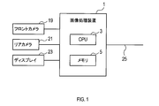
- the configuration of the image processing device 1 will be described with reference to FIGS.
- the image processing device 1 is an in-vehicle device mounted on a vehicle.
- the vehicle on which the image processing apparatus 1 is mounted is referred to as the own vehicle.
- the image processing apparatus 1 is configured around a known microcomputer having a CPU 3 and a semiconductor memory (hereinafter referred to as a memory 5) such as a RAM, a ROM, and a flash memory.
- a memory 5 such as a RAM, a ROM, and a flash memory.
- Various functions of the image processing apparatus 1 are realized by the CPU 3 executing a program stored in a non-transitional physical recording medium.
- the memory 5 corresponds to a non-transitional tangible recording medium that stores a program. Further, by executing this program, a method corresponding to the program is executed.
- the number of microcomputers constituting the image processing apparatus 1 may be one or more.
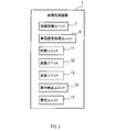
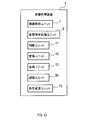
- the image processing apparatus 1 has a function configuration realized by the CPU 3 executing a program, and as shown in FIG. 2, an image acquisition unit 7, a vehicle signal processing unit 9, a determination unit 11, and a conversion unit 12. And a synthesis unit 13, a display stop unit 15, and a display unit 17.
- the method for realizing these elements constituting the image processing apparatus 1 is not limited to software, and some or all of the elements may be realized using hardware that combines a logic circuit, an analog circuit, and the like. .
- the host vehicle includes a front camera 19, a rear camera 21, a display 23, and an in-vehicle network 25.
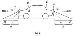
- the front camera 19 is mounted on the front portion of the host vehicle 27.
- the front camera 19 captures a landscape in front of the host vehicle 27 and creates an image.
- the rear camera 21 is mounted on the rear part of the host vehicle 27.
- the rear camera 21 captures a landscape behind the host vehicle 27 and creates an image.
- the optical axis 29 of the front camera 19 and the optical axis 31 of the rear camera 21 are parallel to the front-rear axis of the host vehicle 27.
- the optical axis 29 and the optical axis 31 have a depression angle.
- the optical axis 29 and the optical axis 31 are always constant. Therefore, if the host vehicle 27 is not inclined and the road is flat, the range 33 included in the image captured by the front camera 19 and the range 35 included in the image captured by the rear camera 21 are , Always in a certain position.
- the ranges 33 and 35 include road surfaces.
- a portion close to the host vehicle 27 is a first relative position 37, and a portion farther from the host vehicle 27 than the first relative position 37 is a second relative position 39.
- the second relative position 39 is located on the traveling direction side with respect to the first relative position 37.
- the first relative position 37 and the second relative position 39 each have a certain size.
- first relative position 41 a portion close to the host vehicle 27 is set as a first relative position 41, and a portion farther from the host vehicle 27 than the first relative position 41 is set as a second relative position 43.
- second relative position 43 is located on the traveling direction side with respect to the first relative position 41.
- the first relative position 41 and the second relative position 43 each have a certain size.
- the display 23 is provided in the passenger compartment of the host vehicle 27 as shown in FIG.
- the driver of the host vehicle 27 can visually recognize the display 23.
- the display 23 is controlled by the image processing apparatus 1 and displays an image.
- the in-vehicle network 25 is connected to the image processing apparatus 1.
- the image processing apparatus 1 can acquire a vehicle signal representing the behavior of the host vehicle from the in-vehicle network 25.
- the vehicle signal is a signal representing the vehicle speed of the host vehicle.
- An example of the in-vehicle network 25 is CAN (registered trademark).
- Image Processing Performed by Image Processing Device 1 Image processing that is repeatedly executed by the image processing device 1 at a fixed period I will be described with reference to FIGS.
- the unit of period I is time. In the following, executing the process shown in FIG. 4 once may be referred to as one cycle.
- step 1 of FIG. 4 the image acquisition unit 7 acquires an image using the front camera 19 and the rear camera 21.
- the vehicle signal processing unit 9 acquires a vehicle signal from the in-vehicle network 25.
- step 3 the vehicle signal processing unit 9 stores the vehicle signal acquired in step 2 in the memory 5 in association with the time of acquisition.
- the conversion unit 12 converts the image acquired in step 1 into a bird's eye view image.
- a well-known method can be used as a method for converting into a bird's eye view image.
- a method for converting to a bird's eye view image for example, a method described in JP-A-10-211849 can be used.
- step 5 the conversion unit 12 stores the bird's eye view image converted in step 4 in the memory 5.
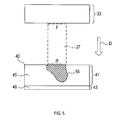
- step 6 as shown in FIG. 5, the image acquisition unit 7 is a part of the bird's eye view image 40 created in step 4, and represents an image (hereinafter, referred to as an area at the first relative position 41).
- the first image 45 is an image that represents an area that was in the first relative position 41 at the time when the rear camera 21 took a picture.
- D in FIG. 5 represents the traveling direction of the host vehicle 27.
- a traveling direction D in FIG. 5 is a direction in which the host vehicle 27 moves backward.
- F represents the front end of the host vehicle 27, and R represents the rear end of the host vehicle 27.
- step 7 the synthesis unit 13 creates the second synthesized image 47 shown in FIG. 6 by the following method.
- an image that is a part of the bird's eye view image 40 created in step 4 and that represents the region at the second relative position 43 is a second image 49.
- the second image 49 is an image representing an area at the second relative position 43 at the time when the rear camera 21 has taken a picture.
- those created in the current cycle are denoted as 49 (i)
- those created in the previous j cycles are denoted as 49 (ij).
- j is a natural number of 1 or more.
- the synthesizing unit 13 calculates the position of the region represented by the second image 49 (ij).
- the position of the region represented by the second image 49 (ij) is a relative position with respect to the host vehicle 27.
- the position of the region represented by the second image 49 (i ⁇ j) is a position moved by ⁇ X j in the direction opposite to the direction D from the position of the region represented by the second image 49 (i).
- the position of the region represented by the second image 49 (i) is equal to the second relative position 43 at the present time.
- ⁇ X j is a distance that the host vehicle 27 has traveled in the direction D from the time when the second image 49 (ij) is created to the present time.
- the synthesizing unit 13 can calculate ⁇ X j using the vehicle signal acquired in Step 3 and stored in Step 4.
- the synthesizing unit 13 selects the second image 49 (ij) whose area to be represented overlaps with the first image 45 among the second images 49 (ij).
- the second image 49 (i-1) to 49 (i-5) overlaps with the first image 45 in the area to be represented.
- the composition unit 13 creates a second composite image 47 by combining all the second images 49 (ij) selected as described above.
- the second image 49 (ij) included in the second composite image 47 is an image acquired earlier than the first image 45 acquired in the current cycle.
- step 8 the determination unit 11 compares the luminance of the first image 45 acquired in the current cycle with the luminance of the second composite image 47 created in step 7. In step 9, the determination unit 11 determines whether or not the difference between the luminance of the first image 45 and the luminance of the second composite image 47 is greater than a preset threshold value. If the difference is larger than the threshold value, the process proceeds to step 10, and if the difference is equal to or smaller than the threshold value, the process proceeds to step 16.
- step 10 the determination unit 11 performs a luminance check for each of the first image 45 and the second composite image 47.
- step 11 based on the result of the brightness check in step 10, whether or not a characteristic characteristic of shadow or illumination light appears for each of the first image 45 and the second composite image 47. The determination unit 11 determines.
- the characteristic peculiar to the shadow is a characteristic that the luminance of the shadowed area is not more than a preset threshold and / or the intensity of a predetermined color component is not less than a preset threshold.
- the characteristic peculiar to the illumination light is a characteristic that the luminance of the area where the illumination light is present is equal to or higher than a preset threshold value.
- Step 12 If a characteristic peculiar to the shadow or the illumination light appears in the first image 45 and a characteristic peculiar to the shadow or the illumination light does not appear in the second composite image 47, the process proceeds to Step 12. If so, go to Step 17.
- step 12 the judgment unit 11 increases the count value by one.
- the count value is a value that is incremented by 1 in this step 12 and reset to 0 in step 16 to be described later.
- step 13 the determination unit 11 determines whether or not the count value exceeds a preset threshold value. If the count value exceeds the threshold value, the process proceeds to step 14, and if the counter value is equal to or less than the threshold value, the process proceeds to step 17.
- step 14 the display stop unit 15 selects a background image as an image to be displayed on the display 23, not a first composite image described later.
- the background image is an image stored in the memory 5 in advance.
- step 15 the display unit 17 displays the background image on the display 23.
- the range in which the background image is displayed is the same as the range in which the first composite image is displayed in step 18 described later.
- step 9 the process proceeds to step 16.
- step 16 the determination unit 11 resets the count value to zero.
- step 17 the composition unit 13 creates a first composite image.
- the creation method of the first composite image is basically the same as the creation method of the second composite image 47. However, when the first composite image is created, the first composite image is created using the first image 45 (ij) acquired in the past cycle, not the second image 49 (ij).
- the first image 45 (ij) is a first image created in the previous j cycles.
- a specific method for creating the first composite image is as follows.
- the synthesizing unit 13 calculates the position of the region represented by the first image 45 (ij).
- the position of the region represented by the first image 45 (ij) is a relative position with respect to the host vehicle 27.
- the composition unit 13 selects the first image 45 (ij) that overlaps the area occupied by the host vehicle 27 in the first image 45 (ij).
- the first images 45 (i-1) to 45 (i-6) overlap with the area occupied by the host vehicle 27.
- the synthesizing unit 13 creates the first synthesized image 51 by combining all the first images 45 (ij) selected as described above.
- the display unit 17 displays the first composite image 51 created in step 17 on the display 23.
- the range in which the first composite image 51 is displayed is the range occupied by the host vehicle 27.
- the first image 45 (i) is displayed below the first composite image 51.
- the first image 45 (i) is the first image 45 created in the current cycle.
- an image 53 obtained by converting an image acquired using the front camera 19 in the current cycle into a bird's eye view image is displayed above the first composite image 51.
- the own vehicle 27 is displayed by computer graphics.
- FIG. 5 there may be a shadow area 55 in the first image 45 representing the area at the first relative position 41.
- This shadow may be the shadow of the host vehicle 27 or the shadow of another target.
- the shadow area 55 corresponds to a specific area having a lower luminance than the surrounding area.
- the shadow area 55 exists in the first image 45, the shadow area 55 hardly exists in the second image 49 representing the area at the second relative position 43. In addition, the shadow area 55 is unlikely to exist in the second synthesized image 47 created by synthesizing the second image 49.
- the image processing apparatus 1 can easily determine whether or not the shadow area 55 exists in the first image 45 by comparing the luminance of the first image 45 with the luminance of the second composite image 47. Can be judged.
- the image processing apparatus 1 can easily determine whether or not there is a region irradiated with illumination light in the first image 45 by the same comparison.
- the area irradiated with the illumination light corresponds to a specific area having higher brightness than the surrounding area.
- illumination light the light of the headlight of another vehicle is mentioned, for example.
- the image processing apparatus 1 can create the first composite image 51 and display it on the display 23. However, if there is a shadow area or an area irradiated with illumination light in the first image 45 constituting the first composite image 51, the display of the first composite image 51 is stopped. Accordingly, it is possible to suppress the display of the first composite image 51 including the shadow area or the area irradiated with the illumination light.
- Second Embodiment 1 Differences from the First Embodiment Since the basic configuration of the second embodiment is the same as that of the first embodiment, description of the common configuration will be omitted, and differences will be mainly described. Note that the same reference numerals as those in the first embodiment indicate the same configuration, and the preceding description is referred to.
- the own vehicle further includes a right camera 57 and a left camera 59 as shown in FIG.
- the right camera 57 captures a landscape on the right side of the host vehicle and creates an image.
- the left camera 59 captures a landscape on the left side of the host vehicle and creates an image.
- the image processing apparatus 1 has a function configuration realized by the CPU 3 executing a program, as shown in FIG. 9, an image acquisition unit 7, a vehicle signal processing unit 9, a determination unit 11, and a conversion unit 12.
- steps 21 to 25 in FIG. 10 is basically the same as the processing in steps 1 to 5 in the first embodiment. However, in step 21, images are acquired from the front camera 19, the rear camera 21, the right camera 57, and the left camera 59, respectively.
- each of the images acquired from the front camera 19, the rear camera 21, the right camera 57, and the left camera 59 is converted into a bird's eye view image.
- 11 shows a bird's eye view image 61 obtained by converting the image obtained from the front camera 19, a bird's eye view image 40 obtained by converting the image obtained from the rear camera 21, a bird's eye view image 63 obtained by converting the image obtained from the right camera 57, A bird's eye view image 65 obtained by converting an image acquired from the camera 59 is shown.
- step 26 the image acquisition unit 7 acquires the bird's eye view images 63 and 65 created in step 24.
- the bird's eye view images 63 and 65 correspond to the first image.
- the relative position 64 of the bird's-eye view image 63 with respect to the host vehicle 27 and the relative position 66 of the bird's-eye view image 65 with respect to the host vehicle 27 correspond to the first relative position.
- step 27 the synthesizing unit 13 creates the second synthesized image 69 shown in FIG. 12 by the following method.
- a second image 71 an image that is a part of the bird's-eye view image 61 and that represents the region at the second relative position 39 is referred to as a second image 71.
- 71 (i) one created in the current cycle
- 71 (ij) one created in the previous j cycles
- j is a natural number of 1 or more.
- the synthesizing unit 13 calculates the position of the region represented by the second image 71 (ij).
- the position of the region represented by the second image 71 (ij) is a relative position with respect to the host vehicle 27.
- the position of the region represented by the second image 71 (i ⁇ j) is a position moved in the direction opposite to the direction D by ⁇ X j from the position of the region represented by the second image 71 (i).
- the position of the region represented by the second image 71 (i) is equal to the second relative position 39 at the present time.
- ⁇ X j is a distance that the host vehicle 27 has traveled in the direction D from the time when the second image 71 (ij) is created to the present time.
- the synthesizing unit 13 can calculate ⁇ X j using the vehicle signal acquired in step 23 and stored in step 24.
- the synthesizing unit 13 selects the second image 71 (ij) in which the area to be represented overlaps with the bird's-eye view images 63 and 65 from the second image 71 (ij).
- the second images 71 (i-5) to 71 (i-10) overlap with the bird's eye view images 63 and 65 in the area to be represented.
- the synthesis unit 13 creates a second synthesized image 69 by combining all the second images 71 (ij) selected as described above.
- step 28 the determination unit 11 compares the brightness of the bird's eye view images 63 and 65 acquired in step 26 with the brightness of the second composite image 69 created in step 27. In step 29, the determination unit 11 determines whether or not the difference between the brightness of the bird's eye view images 63 and 65 and the brightness of the second composite image 69 is greater than a preset threshold value. If the difference is larger than the threshold value, the process proceeds to step 30, and if the difference is equal to or smaller than the threshold value, the process proceeds to step 34.
- step 30 the determination unit 11 checks the luminance of each of the bird's eye view images 63 and 65 and the second composite image 69. In step 31, based on the result of the luminance check in step 30, the determination unit 11 determines whether or not a characteristic peculiar to the shadow appears in each of the bird's eye view images 63 and 65 and the second composite image 69. Judgment. If the bird's eye view images 63 and 65 show a characteristic peculiar to the shadow, and the second composite image 69 does not show a characteristic peculiar to the shadow, the process proceeds to step 32. Otherwise, the process goes to step 34. move on.
- the recognition stop unit 58 stops the recognition of the lane marker.
- a lane marker means what divides a traveling lane. Examples of the lane marker include a white line.
- step 33 the recognition stop unit 58 displays an error on the display 23.
- the error display means that the lane marker cannot be recognized. If a negative determination is made in step 29 or step 31, the process proceeds to step 34.
- step 34 the recognition unit 56 performs a process of recognizing the lane marker by a known method. The outline of the process is as follows. FIG. 11 shows an example of the lane marker 72.
- feature points are detected.
- the feature point is a point where the luminance change is larger than a preset threshold value.
- an approximate curve passing through the feature points is calculated.
- the approximate curve whose lane marker-likeness is equal to or greater than a predetermined threshold is recognized as a lane marker.
- step 35 the recognition unit 56 outputs the recognition result in the step 34 to another device.
- Other apparatuses can use the recognition result of the lane marker for the driving support process. Examples of the driving support process include lane keep assist.
- the image processing apparatus 1 stops the recognition of the lane marker 72 when the shadow area 55 exists in the bird's eye view images 63 and 65. As a result, it is possible to suppress erroneous recognition of the lane marker 72 due to the shadow area 55.
- the basic configuration of the third embodiment is the same as that of the second embodiment, the description of the common configuration will be omitted, and the differences will be mainly described.
- symbol as 2nd Embodiment shows the same structure, Comprising: Prior description is referred.
- the image processing apparatus 1 has a function configuration realized by the CPU 3 executing a program, and as shown in FIG. 13, an image acquisition unit 7, a vehicle signal processing unit 9, a determination unit 11, and a conversion unit 12. And a synthesis unit 13, a recognition unit 56, and a condition change unit 73.
- the condition changing unit 73 calculates the coordinates of the shadow area in the bird's eye view images 63 and 65.
- the condition changing unit 73 changes the threshold value when detecting a feature point in step 54 described later. That is, among the bird's eye view images 63 and 65, the threshold for detecting the feature point is set larger than the normal value in the shadow area. Outside the shadow area, the threshold value when detecting the feature point is a normal value.
- the threshold for detecting feature points corresponds to the setting conditions for recognizing lane markers.
- step 54 the recognition unit 56 detects feature points in the bird's eye view images 63 and 65.
- the threshold value used for feature point detection is the value changed in step 53.
- step 55 the recognition unit 56 removes the feature points detected in step 54 that are on the boundary of the shadow area.
- step 56 the recognition unit 56 calculates an approximate curve that passes through the feature points.
- the feature points used for calculating the approximate curve are those detected in step 54 and remaining without being removed in step 55.
- step 57 the recognition unit 56 recognizes, as a lane marker, an approximation curve whose lane marker likelihood is greater than or equal to a predetermined threshold value.
- step 58 the recognition unit 56 outputs the recognition result in step 57 or step 59 described later to another device.
- step 59 the recognition unit 56 recognizes the lane marker with normal settings.
- the normal setting means that the threshold value used for the feature point detection is set to a normal value in the whole bird's-eye view images 63 and 65. Further, the normal setting means a setting that does not perform the process of excluding the feature points on the boundary of the shadow area.
- the setting condition for recognizing the lane marker is different from that when the shadow region 55 does not exist. As a result, erroneous recognition of the lane marker due to the shadow area can be suppressed.
- step 53 the image processing apparatus 1 sets a threshold value for detecting a feature point in the shadow area 55 to be larger than a normal value.
- step 55 the feature points on the boundary line of the shadow area 55 are excluded from the detected feature points. As a result, erroneous recognition of the lane marker due to the shadow area 55 can be further suppressed.
- the luminance of the first image 45 may be compared with the luminance of the second image 49 (ij).
- Step 9 it may be determined whether or not the difference between the luminance of the first image 45 and the luminance of the second image 49 (ij) is greater than a preset threshold value.
- Step 28 in the second embodiment and Step 48 in the third embodiment the brightness of the bird's eye view images 63 and 65 may be compared with the brightness of the second image 71 (ij).
- Step 29 in the second embodiment and Step 49 in the third embodiment the difference between the brightness of the bird's-eye view images 63 and 65 and the brightness of the second image 71 (ij) is set in advance. It may be determined whether or not it is greater than the threshold value.
- the image to be compared in step 8 in the first embodiment is an image representing the first relative position 41 before being converted into the bird's eye view image, and a second relative position 43 before being converted into the bird's eye view image. It may be an image showing.
- the images to be compared in Step 28 in the second embodiment and Step 48 in the third embodiment are images acquired from the right camera 57 and the left camera 59 before being converted into a bird's eye view image, and before being converted into a bird's eye view image.
- An image representing the second relative position 39 may be used.
- step 8 of the first embodiment the strength of the predetermined color component CI in the first image 45 may be compared with the strength of the same color component CI in the second composite image 47.
- the determination unit 11 determines whether the difference in the intensity of the color component CI between the first image 45 and the second composite image 47 is greater than a preset threshold value. May be. If the difference in the intensity of the color component CI is larger than the threshold value, the process proceeds to step 10, and if the difference in the intensity of the color component CI is equal to or less than the threshold value, the process proceeds to step 16.
- the intensity of the predetermined color component CI is compared and the predetermined color component CI is compared.
- a determination may be made based on the difference in strength.
- the color component CI examples include a blue component.
- the brightness contrast and the strength contrast of the predetermined color component CI may be performed for the first image 45 and the second composite image 47, respectively. .
- step 9 the determination may be made based on the difference in luminance between the first image 45 and the second composite image 47 and the difference in the intensity of the color component CI. For example, if both the luminance difference and the color component intensity difference are larger than the threshold value, the process can proceed to step 10, and otherwise, the process can proceed to step 16.
- either of the difference in luminance and the difference in intensity of the color component can proceed to step 10 if it is larger than the threshold value, or to step 16 otherwise.
- both the luminance contrast and the intensity contrast of the predetermined color component CI are used. Determination may be made based on the comparison results.
- a plurality of functions of one constituent element in the above embodiment may be realized by a plurality of constituent elements, or a single function of one constituent element may be realized by a plurality of constituent elements. . Further, a plurality of functions possessed by a plurality of constituent elements may be realized by one constituent element, or one function realized by a plurality of constituent elements may be realized by one constituent element. Moreover, you may abbreviate
- at least a part of the configuration of the above embodiment may be added to or replaced with the configuration of the other embodiment.
- all the aspects included in the technical idea specified only by the wording described in the claims are embodiments of the present disclosure.
- a system including the image processing apparatus 1 as a constituent element, a program for causing a computer to function as the image processing apparatus 1, a non-transitive semiconductor memory or the like in which the program is recorded The present disclosure can also be realized in various forms such as an actual recording medium, an image processing method, a composite image creation method, and a lane marker recognition method.
Landscapes
- Engineering & Computer Science (AREA)
- Physics & Mathematics (AREA)
- General Physics & Mathematics (AREA)
- Theoretical Computer Science (AREA)
- Multimedia (AREA)
- Signal Processing (AREA)
- Software Systems (AREA)
- Computer Vision & Pattern Recognition (AREA)
- Geometry (AREA)
- Image Processing (AREA)
- Image Analysis (AREA)
- Closed-Circuit Television Systems (AREA)
- Traffic Control Systems (AREA)
Abstract
画像処理装置(1)は、画像取得ユニット(7)と、判断ユニット(11)とを備える。画像取得ユニットは、カメラを用いて、第1の相対位置にある領域を表す第1の画像、及び、第1の相対位置よりも車両の進行方向側に位置する第2の相対位置にある領域を表す第2の画像を取得する。判断ユニットは、第1の画像と、第1の画像よりも早く取得され、第1の画像と重複する領域を表す第2の画像について、輝度、及び/又は、所定の色成分の強さを対比することで、周囲に比べて輝度が高い、又は、周囲に比べて輝度が低い特定領域が第1の画像に存在するか否かを判断する。
Description
本国際出願は、2016年4月26日に日本国特許庁に出願された日本国特許出願第2016-088203号に基づく優先権を主張するものであり、日本国特許出願第2016-088203号の全内容を本国際出願に参照により援用する。
本開示は、画像処理装置、画像処理方法、及びプログラムに関する。
従来、車載カメラを用いて車両の周辺の画像を取得し、その画像を用いて様々な処理を行う技術が知られている。例えば、取得した画像においてレーンマーカを認識する技術が知られている。
また、以下のような画像処理が知られている。まず、車載カメラを用いて、車両の周辺の画像を、時間差をおいて複数取得する。次に、複数の画像のそれぞれを鳥瞰図画像に変換する。次に、複数の鳥瞰図画像を合成して合成画像を作成する。このような画像処理は、特許文献1に開示されている。
発明者の詳細な検討の結果、以下の課題が見出された。車載カメラを用いて取得した画像中に、周囲に比べて輝度が低い領域や、周囲に比べて輝度が高い領域が存在することがある。周囲に比べて輝度が低い領域としては、例えば、車両の影の領域がある。また、周囲に比べて輝度が高い領域としては、例えば、ヘッドライト等の照明光が照射された領域等がある。車載カメラを用いて取得した画像中に、周囲に比べて輝度が低い領域や、周囲に比べて輝度が高い領域が存在する場合、画像を用いた処理を適切に行えないことがある。
本開示の一局面は、カメラを用いて取得した画像中に、周囲に比べて輝度が低い領域や、周囲に比べて輝度が高い領域が存在するか否かを判断することができる画像処理装置、画像処理方法、及びプログラムを提供することが好ましい。
本開示の一態様である画像処理装置は、車両に搭載された少なくとも1つのカメラを用いて、車両に対して第1の相対位置にある領域を表す第1の画像、及び、第1の相対位置よりも車両の進行方向側に位置する第2の相対位置にある領域を表す第2の画像を取得する画像取得ユニットと、第1の画像と、第1の画像よりも早く取得され、第1の画像と重複する領域を表す第2の画像とについて、輝度、及び/又は、所定の色成分の強さを対比することで、周囲に比べて輝度が高い、又は、周囲に比べて輝度が低い特定領域が第1の画像に存在するか否かを判断する判断ユニットとを備える。
本開示の一態様である画像処理装置によれば、第1の画像内に、周囲に比べて輝度が高い、又は、周囲に比べて輝度が低い特定領域が存在するか否かを容易に判断することができる。
本開示の別の態様である画像処理方法は、車両に搭載されたカメラを用いて、車両に対して第1の相対位置にある領域を表す第1の画像、及び、第1の相対位置よりも車両の進行方向側に位置する第2の相対位置にある領域を表す第2の画像を取得し、第1の画像と、第1の画像よりも早く取得され、第1の画像と重複する領域を表す第2の画像とについて、輝度、及び/又は、所定の色成分の強さを対比することで、周囲に比べて輝度が高い、又は、周囲に比べて輝度が低い特定領域が第1の画像に存在するか否かを判断する。
本開示の別の態様である画像処理方法によれば、第1の画像内に、周囲に比べて輝度が高い、又は、周囲に比べて輝度が低い特定領域が存在するか否かを容易に判断することができる。
なお、特許請求の範囲に記載した括弧内の符号は、一つの態様として後述する実施形態に記載の具体的手段との対応関係を示すものであって、本開示の技術的範囲を限定するものではない。
本開示の実施形態を図面に基づき説明する。
<第1実施形態>
1.画像処理装置1の構成
画像処理装置1の構成を、図1~図3に基づき説明する。画像処理装置1は、車両に搭載される車載装置である。以下では、画像処理装置1を搭載する車両を自車両とする。画像処理装置1は、CPU3と、RAM、ROM、フラッシュメモリ等の半導体メモリ(以下、メモリ5とする)と、を有する周知のマイクロコンピュータを中心に構成される。画像処理装置1の各種機能は、CPU3が非遷移的実体的記録媒体に格納されたプログラムを実行することにより実現される。この例では、メモリ5が、プログラムを格納した非遷移的実体的記録媒体に該当する。また、このプログラムの実行により、プログラムに対応する方法が実行される。なお、画像処理装置1を構成するマイクロコンピュータの数は1つでも複数でもよい。
<第1実施形態>
1.画像処理装置1の構成
画像処理装置1の構成を、図1~図3に基づき説明する。画像処理装置1は、車両に搭載される車載装置である。以下では、画像処理装置1を搭載する車両を自車両とする。画像処理装置1は、CPU3と、RAM、ROM、フラッシュメモリ等の半導体メモリ(以下、メモリ5とする)と、を有する周知のマイクロコンピュータを中心に構成される。画像処理装置1の各種機能は、CPU3が非遷移的実体的記録媒体に格納されたプログラムを実行することにより実現される。この例では、メモリ5が、プログラムを格納した非遷移的実体的記録媒体に該当する。また、このプログラムの実行により、プログラムに対応する方法が実行される。なお、画像処理装置1を構成するマイクロコンピュータの数は1つでも複数でもよい。
画像処理装置1は、CPU3がプログラムを実行することで実現される機能の構成として、図2に示すように、画像取得ユニット7と、車両信号処理ユニット9と、判断ユニット11と、変換ユニット12と、合成ユニット13と、表示停止ユニット15と、表示ユニット17と、を備える。画像処理装置1を構成するこれらの要素を実現する手法はソフトウェアに限るものではなく、その一部又は全部の要素を、論理回路やアナログ回路等を組み合わせたハードウェアを用いて実現してもよい。
自車両は、画像処理装置1に加えて、フロントカメラ19、リアカメラ21、ディスプレイ23、及び車載ネットワーク25を備える。図3に示すように、フロントカメラ19は、自車両27の前部に搭載されている。フロントカメラ19は、自車両27から見て前方にある風景を撮影し、画像を作成する。また、リアカメラ21は、自車両27の後部に搭載されている。リアカメラ21は、自車両27から見て後方にある風景を撮影し、画像を作成する。
自車両27を上方から見たとき、フロントカメラ19の光軸29及びリアカメラ21の光軸31は、自車両27の前後軸と平行である。また、光軸29及び光軸31は俯角を有する。自車両27を基準としたとき、光軸29及び光軸31は常に一定である。そのため、自車両27の傾きがなく、道路が平坦であれば、フロントカメラ19が撮影する画像に含まれる範囲33、及びリアカメラ21が撮影する画像に含まれる範囲35は、自車両27に対し、常に一定の位置にある。範囲33、35には、路面が含まれる。
範囲33のうち、自車両27に近い部分を第1の相対位置37とし、第1の相対位置37よりも自車両27から遠い部分を第2の相対位置39とする。自車両27の進行方法が前方である場合、第2の相対位置39は、第1の相対位置37よりも進行方向側に位置する。第1の相対位置37及び第2の相対位置39は、それぞれ一定の大きさを有する。
範囲35のうち、自車両27に近い部分を第1の相対位置41とし、第1の相対位置41よりも自車両27から遠い部分を第2の相対位置43とする。自車両27の進行方法が後方である場合、第2の相対位置43は、第1の相対位置41よりも進行方向側に位置する。第1の相対位置41及び第2の相対位置43は、それぞれ一定の大きさを有する。
ディスプレイ23は、図3に示すように、自車両27の車室内に設けられている。自車両27のドライバはディスプレイ23を視認可能である。ディスプレイ23は、画像処理装置1により制御され、画像を表示する。
車載ネットワーク25は、画像処理装置1に接続している。画像処理装置1は、車載ネットワーク25から、自車両の挙動を表す車両信号を取得することができる。車両信号は、具体的には、自車両の車速を表す信号である。車載ネットワーク25としては、例えば、CAN(登録商標)が挙げられる。
2.画像処理装置1が実行する画像処理
画像処理装置1が一定の周期Iで繰り返し実行する画像処理を、図4~図7に基づき説明する。周期Iの単位は時間である。以下では、図4に示す処理を1回実行することを、1サイクルということがある。
画像処理装置1が一定の周期Iで繰り返し実行する画像処理を、図4~図7に基づき説明する。周期Iの単位は時間である。以下では、図4に示す処理を1回実行することを、1サイクルということがある。
なお、ここでは、自車両が後進する場合を例に挙げて説明する。自車両が前進する場合の処理も、リアカメラ21で取得した画像の代わりにフロントカメラ19で取得した画像を用いる点以外は同様である。
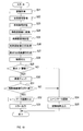
図4のステップ1では、画像取得ユニット7が、フロントカメラ19及びリアカメラ21を用いて画像を取得する。
ステップ2では、車両信号処理ユニット9が、車載ネットワーク25から車両信号を取得する。
ステップ2では、車両信号処理ユニット9が、車載ネットワーク25から車両信号を取得する。
ステップ3では、車両信号処理ユニット9が、前記ステップ2で取得した車両信号を、それを取得した時刻と関連付けてメモリ5に記憶する。
ステップ4では、変換ユニット12が、前記ステップ1で取得した画像を鳥瞰図画像に変換する。鳥瞰図画像に変換する方法として、周知の方法を用いることができる。鳥瞰図画像に変換する方法の例として、例えば、特開平10-211849号公報に記載されている方法等を用いることができる。
ステップ4では、変換ユニット12が、前記ステップ1で取得した画像を鳥瞰図画像に変換する。鳥瞰図画像に変換する方法として、周知の方法を用いることができる。鳥瞰図画像に変換する方法の例として、例えば、特開平10-211849号公報に記載されている方法等を用いることができる。
ステップ5では、変換ユニット12が、前記ステップ4で変換した鳥瞰図画像をメモリ5に記憶する。
ステップ6では、図5に示すように、画像取得ユニット7が、前記ステップ4で作成した鳥瞰図画像40の一部であって、第1の相対位置41にあった領域を表す画像(以下では、第1の画像45とする)を取得する。第1の画像45は、リアカメラ21が撮影を行った時点において、第1の相対位置41にあった領域を表す画像である。なお、図5におけるDは自車両27の進行方向を表す。図5における進行方向Dは、自車両27が後進する方向である。図5におけるFは自車両27の前端を表し、Rは自車両27の後端を表す。
ステップ6では、図5に示すように、画像取得ユニット7が、前記ステップ4で作成した鳥瞰図画像40の一部であって、第1の相対位置41にあった領域を表す画像(以下では、第1の画像45とする)を取得する。第1の画像45は、リアカメラ21が撮影を行った時点において、第1の相対位置41にあった領域を表す画像である。なお、図5におけるDは自車両27の進行方向を表す。図5における進行方向Dは、自車両27が後進する方向である。図5におけるFは自車両27の前端を表し、Rは自車両27の後端を表す。
ステップ7では、合成ユニット13が、図6に示す第2の合成画像47を、以下の方法で作成する。
図5に示すように、前記ステップ4で作成する鳥瞰図画像40の一部であって、第2の相対位置43にある領域を表す画像を、第2の画像49とする。第2の画像49は、リアカメラ21が撮影を行った時点において、第2の相対位置43にあった領域を表す画像である。以下では、第2の画像49のうち、今回のサイクルで作成されたものを49(i)と表記し、j回前のサイクルで作成されたものを49(i-j)と表記する。jは1以上の自然数である。
図5に示すように、前記ステップ4で作成する鳥瞰図画像40の一部であって、第2の相対位置43にある領域を表す画像を、第2の画像49とする。第2の画像49は、リアカメラ21が撮影を行った時点において、第2の相対位置43にあった領域を表す画像である。以下では、第2の画像49のうち、今回のサイクルで作成されたものを49(i)と表記し、j回前のサイクルで作成されたものを49(i-j)と表記する。jは1以上の自然数である。
合成ユニット13は、第2の画像49(i-j)が表す領域の位置を算出する。第2の画像49(i-j)が表す領域の位置は、自車両27を基準とする相対的な位置である。第2の画像49(i-j)が表す領域の位置は、第2の画像49(i)が表す領域の位置から、ΔXjだけ、方向Dとは反対方向に移動した位置である。第2の画像49(i)が表す領域の位置は、現時点における第2の相対位置43に等しい。
ΔXjとは、第2の画像49(i-j)を作成した時点から現時点までに自車両27が方向Dに進行した距離である。合成ユニット13は、前記ステップ3で取得し、前記ステップ4で記憶した車両信号を用いて、ΔXjを算出することができる。
次に、合成ユニット13は、第2の画像49(i-j)のうち、第1の画像45と、表す領域が重複する第2の画像49(i-j)を選択する。図6に示す例では、第2の画像49(i-1)~49(i-5)が、第1の画像45と、表す領域が重複する。
次に、合成ユニット13は、上記のように選択した第2の画像49(i-j)を全て組み合わせて、第2の合成画像47を作成する。なお、第2の合成画像47に含まれる第2の画像49(i-j)は、今回のサイクルで取得した第1の画像45よりも早く取得された画像である。
ステップ8では、判断ユニット11が、今回のサイクルで取得した第1の画像45の輝度と、前記ステップ7で作成した第2の合成画像47の輝度とを対比する。
ステップ9では、第1の画像45の輝度と、第2の合成画像47の輝度との差分が、予め設定された閾値より大きいか否かを判断ユニット11が判断する。差分が閾値より大きい場合はステップ10に進み、差分が閾値以下である場合はステップ16に進む。
ステップ9では、第1の画像45の輝度と、第2の合成画像47の輝度との差分が、予め設定された閾値より大きいか否かを判断ユニット11が判断する。差分が閾値より大きい場合はステップ10に進み、差分が閾値以下である場合はステップ16に進む。
ステップ10では、判断ユニット11が、第1の画像45と、第2の合成画像47とのそれぞれについて、輝度のチェックを行う。
ステップ11では、前記ステップ10での輝度のチェックの結果に基づき、第1の画像45と、第2の合成画像47とのそれぞれについて、影又は照明光に特有の特徴が表れているか否かを判断ユニット11が判断する。
ステップ11では、前記ステップ10での輝度のチェックの結果に基づき、第1の画像45と、第2の合成画像47とのそれぞれについて、影又は照明光に特有の特徴が表れているか否かを判断ユニット11が判断する。
影に特有の特徴とは、影のある領域の輝度が予め設定された閾値以下、及び/又は、所定の色成分の強さが予め設定された閾値以上であるという特徴である。照明光に特有の特徴とは、照明光のある領域の輝度が予め設定された閾値以上であるという特徴である。
第1の画像45に影又は照明光に特有の特徴が表れており、第2の合成画像47には影又は照明光に特有の特徴が表れていない場合は、ステップ12に進み、それ以外の場合はステップ17に進む。
ステップ12では、判断ユニット11が、カウント値を1つだけ増す。なお、カウント値は、本ステップ12で1つだけ増し、後述するステップ16で0にリセットされる値である。
ステップ13では、カウント値が予め設定された閾値を超えたか否かを判断ユニット11が判断する。カウント値が閾値を超えた場合はステップ14に進み、カウンタ値が閾値以下である場合はステップ17に進む。
ステップ14では、表示停止ユニット15が、ディスプレイ23に表示する画像として、後述する第1の合成画像ではなく、背景画像を選択する。背景画像は、予めメモリ5に記憶されている画像である。
ステップ15では、表示ユニット17が、背景画像をディスプレイ23に表示する。背景画像を表示する範囲は、後述するステップ18で第1の合成画像を表示する範囲と同じである。
前記ステップ9で否定判断した場合はステップ16に進む。ステップ16では、判断ユニット11が、カウント値を0にリセットする。
ステップ17では、合成ユニット13が、第1の合成画像を作成する。第1の合成画像の作成方法は、基本的には第2の合成画像47の作成方法と同様である。ただし、第1の合成画像を作成する場合は、第2の画像49(i-j)ではなく、過去のサイクルにおいて取得した第1の画像45(i-j)を用いて作成する。第1の画像45(i-j)は、j回前のサイクルにおいて作成した第1の画像である。
ステップ17では、合成ユニット13が、第1の合成画像を作成する。第1の合成画像の作成方法は、基本的には第2の合成画像47の作成方法と同様である。ただし、第1の合成画像を作成する場合は、第2の画像49(i-j)ではなく、過去のサイクルにおいて取得した第1の画像45(i-j)を用いて作成する。第1の画像45(i-j)は、j回前のサイクルにおいて作成した第1の画像である。
第1の合成画像の具体的な作成方法は以下のとおりである。合成ユニット13は、第1の画像45(i-j)が表す領域の位置を算出する。第1の画像45(i-j)が表す領域の位置は、自車両27を基準とする相対的な位置である。第1の画像45(i-j)が表す領域の位置は、第1の相対位置41から、ΔXjだけ、方向Dとは反対方向に移動した位置である。
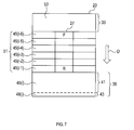
次に、合成ユニット13は、第1の画像45(i-j)のうち、自車両27が占める領域と重複する第1の画像45(i-j)を選択する。図7に示す例では、第1の画像45(i-1)~45(i-6)が、自車両27が占める領域と重複する。
次に、合成ユニット13は、上記のように選択した第1の画像45(i-j)を全て組み合わせて、第1の合成画像51を作成する。
ステップ18では、表示ユニット17が、前記ステップ17で作成した第1の合成画像51をディスプレイ23に表示する。第1の合成画像51を表示する範囲は、自車両27が占める範囲である。
ステップ18では、表示ユニット17が、前記ステップ17で作成した第1の合成画像51をディスプレイ23に表示する。第1の合成画像51を表示する範囲は、自車両27が占める範囲である。
なお、図7に示す例では、第1の合成画像51の下側に、第1の画像45(i)を表示する。第1の画像45(i)は、今回のサイクルで作成した第1の画像45である。また、図7に示す例では、第1の合成画像51の上側に、今回のサイクルにおいてフロントカメラ19を用いて取得した画像を鳥瞰図画像に変換した画像53を表示する。また、図7に示す例では、自車両27を、コンピュータグラフィックにより表示する。
3.画像処理装置1が奏する効果
(1A)図5に示すように、第1の相対位置41にある領域を表す第1の画像45内に影の領域55が存在する場合がある。この影は、自車両27の影であってもよいし、その他の物標の影であってもよい。影の領域55は、その周囲に比べて輝度が低い特定領域に対応する。
(1A)図5に示すように、第1の相対位置41にある領域を表す第1の画像45内に影の領域55が存在する場合がある。この影は、自車両27の影であってもよいし、その他の物標の影であってもよい。影の領域55は、その周囲に比べて輝度が低い特定領域に対応する。
第1の画像45内に影の領域55が存在する場合でも、第2の相対位置43にある領域を表す第2の画像49内には、影の領域55は存在しにくい。また、第2の画像49を合成して作成される第2の合成画像47内にも、影の領域55は存在しにくい。
画像処理装置1は、第1の画像45の輝度と、第2の合成画像47の輝度とを対比することで、第1の画像45内に、影の領域55が存在するか否かを容易に判断することができる。
また、画像処理装置1は、同様の対比により、第1の画像45内に、照明光が照射されている領域が存在するか否かを容易に判断することができる。照明光が照射されている領域は、その周囲に比べて輝度が高い特定領域に対応する。照明光としては、例えば、他の車両のヘッドライトの光が挙げられる。
(1B)画像処理装置1は、第1の合成画像51を作成し、ディスプレイ23に表示することができる。ただし、第1の合成画像51を構成する第1の画像45に、影の領域、又は、照明光が照射された領域が存在する場合、第1の合成画像51の表示を停止する。そのことにより、影の領域、又は、照明光が照射された領域を含む第1の合成画像51を表示してしまうことを抑制できる。
<第2実施形態>
1.第1実施形態との相違点
第2実施形態は、基本的な構成は第1実施形態と同様であるため、共通する構成については説明を省略し、相違点を中心に説明する。なお、第1実施形態と同じ符号は、同一の構成を示すものであって、先行する説明を参照する。
<第2実施形態>
1.第1実施形態との相違点
第2実施形態は、基本的な構成は第1実施形態と同様であるため、共通する構成については説明を省略し、相違点を中心に説明する。なお、第1実施形態と同じ符号は、同一の構成を示すものであって、先行する説明を参照する。
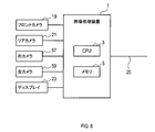
自車両は、図8に示すように、さらに、右カメラ57、及び左カメラ59を備える。右カメラ57は、自車両の右側における風景を撮影し、画像を作成する。左カメラ59は、自車両の左側における風景を撮影し、画像を作成する。
画像処理装置1は、CPU3がプログラムを実行することで実現される機能の構成として、図9に示すように、画像取得ユニット7と、車両信号処理ユニット9と、判断ユニット11と、変換ユニット12と、合成ユニット13と、認識ユニット56と、認識停止ユニット58と、を備える。
2.画像処理装置1が実行する処理
画像処理装置1が実行する処理を図10~図12に基づき説明する。なお、ここでは、自車両が前進する場合を例に挙げて説明する。
画像処理装置1が実行する処理を図10~図12に基づき説明する。なお、ここでは、自車両が前進する場合を例に挙げて説明する。
図10におけるステップ21~25の処理は、基本的には、第1実施形態におけるステップ1~5の処理と同様である。
ただし、ステップ21では、フロントカメラ19、リアカメラ21、右カメラ57、及び左カメラ59からそれぞれ画像を取得する。
ただし、ステップ21では、フロントカメラ19、リアカメラ21、右カメラ57、及び左カメラ59からそれぞれ画像を取得する。
また、ステップ24では、フロントカメラ19、リアカメラ21、右カメラ57、及び左カメラ59から取得した画像のそれぞれを鳥瞰図画像に変換する。図11に、フロントカメラ19から取得した画像を変換した鳥瞰図画像61と、リアカメラ21から取得した画像を変換した鳥瞰図画像40と、右カメラ57から取得した画像を変換した鳥瞰図画像63と、左カメラ59から取得した画像を変換した鳥瞰図画像65と、を示す。
ステップ26では、画像取得ユニット7が、前記ステップ24で作成した鳥瞰図画像63、65を取得する。鳥瞰図画像63、65は、第1の画像に対応する。また、自車両27に対する、鳥瞰図画像63の相対位置64と、自車両27に対する、鳥瞰図画像65の相対位置66とは、第1の相対位置に対応する。
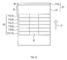
ステップ27では、合成ユニット13が、図12に示す第2の合成画像69を、以下の方法で作成する。
図11に示すように、鳥瞰図画像61の一部であって、第2の相対位置39にある領域を表す画像を、第2の画像71とする。以下では、第2の画像71のうち、今回のサイクルで作成されたものを71(i)と表記し、j回前のサイクルで作成されたものを71(i-j)と表記する。jは1以上の自然数である。
図11に示すように、鳥瞰図画像61の一部であって、第2の相対位置39にある領域を表す画像を、第2の画像71とする。以下では、第2の画像71のうち、今回のサイクルで作成されたものを71(i)と表記し、j回前のサイクルで作成されたものを71(i-j)と表記する。jは1以上の自然数である。
合成ユニット13は、第2の画像71(i-j)が表す領域の位置を算出する。第2の画像71(i-j)が表す領域の位置は、自車両27を基準とする相対的な位置である。第2の画像71(i-j)が表す領域の位置は、第2の画像71(i)が表す領域の位置から、ΔXjだけ、方向Dとは反対方向に移動した位置である。第2の画像71(i)が表す領域の位置は、現時点における第2の相対位置39に等しい。
ΔXjとは、第2の画像71(i-j)を作成した時点から現時点までに自車両27が方向Dに進行した距離である。合成ユニット13は、前記ステップ23で取得し、前記ステップ24で記憶した車両信号を用いて、ΔXjを算出することができる。
次に、合成ユニット13は、第2の画像71(i-j)のうち、鳥瞰図画像63、65と、表す領域が重複する第2の画像71(i-j)を選択する。図12に示す例では、第2の画像71(i-5)~71(i-10)が、鳥瞰図画像63、65と、表す領域が重複する。次に、合成ユニット13は、上記のように選択した第2の画像71(i-j)を全て組み合わせて、第2の合成画像69を作成する。
ステップ28では、判断ユニット11が、前記ステップ26で取得した鳥瞰図画像63、65の輝度と、前記ステップ27で作成した第2の合成画像69の輝度とを対比する。
また、ステップ29では、鳥瞰図画像63、65の輝度と、第2の合成画像69の輝度との差分が、予め設定された閾値より大きいか否かを判断ユニット11が判断する。差分が閾値より大きい場合はステップ30に進み、差分が閾値以下である場合はステップ34に進む。
また、ステップ29では、鳥瞰図画像63、65の輝度と、第2の合成画像69の輝度との差分が、予め設定された閾値より大きいか否かを判断ユニット11が判断する。差分が閾値より大きい場合はステップ30に進み、差分が閾値以下である場合はステップ34に進む。
ステップ30では、判断ユニット11が、鳥瞰図画像63、65と、第2の合成画像69とのそれぞれについて、輝度のチェックを行う。
ステップ31では、前記ステップ30での輝度のチェックの結果に基づき、鳥瞰図画像63、65と、第2の合成画像69とのそれぞれについて、影に特有の特徴が表れているか否かを判断ユニット11が判断する。鳥瞰図画像63、65には影に特有の特徴が表れており、第2の合成画像69には影に特有の特徴が表れていない場合は、ステップ32に進み、それ以外の場合はステップ34に進む。
ステップ31では、前記ステップ30での輝度のチェックの結果に基づき、鳥瞰図画像63、65と、第2の合成画像69とのそれぞれについて、影に特有の特徴が表れているか否かを判断ユニット11が判断する。鳥瞰図画像63、65には影に特有の特徴が表れており、第2の合成画像69には影に特有の特徴が表れていない場合は、ステップ32に進み、それ以外の場合はステップ34に進む。
ステップ32では、認識停止ユニット58が、レーンマーカの認識を停止する。レーンマーカとは、走行車線を区画するものを意味する。レーンマーカとして、例えば、白線等が挙げられる。
ステップ33では、認識停止ユニット58が、ディスプレイ23にエラー表示を行う。そのエラー表示は、レーンマーカを認識できないことを意味する。
前記ステップ29又は前記ステップ31で否定判断した場合はステップ34に進む。ステップ34では、認識ユニット56が、周知の方法により、レーンマーカを認識する処理を行う。その処理の概略は以下のとおりである。図11に、レーンマーカ72の例を示す。
前記ステップ29又は前記ステップ31で否定判断した場合はステップ34に進む。ステップ34では、認識ユニット56が、周知の方法により、レーンマーカを認識する処理を行う。その処理の概略は以下のとおりである。図11に、レーンマーカ72の例を示す。
鳥瞰図画像63、65において、特徴点を検出する。特徴点とは、輝度変化が予め設定された閾値より大きい点である。次に、特徴点を通る近似曲線を算出する。次に、近似曲線のうち、レーンマーカらしさが所定の閾値以上であるものを、レーンマーカとして認識する。
ステップ35では、認識ユニット56が、前記ステップ34における認識結果を他の装置に出力する。他の装置は、レーンマーカの認識結果を、運転支援処理に使用することができる。運転支援処理としては、例えば、レーンキープアシスト等が挙げられる。
3.画像処理装置1が奏する効果
以上詳述した第2実施形態によれば、前述した第1実施形態の効果(1A)に加え、以下の効果が得られる。
以上詳述した第2実施形態によれば、前述した第1実施形態の効果(1A)に加え、以下の効果が得られる。
(2A)画像処理装置1は、図11に示すように、鳥瞰図画像63、65に影の領域55が存在する場合、レーンマーカ72の認識を停止する。そのことにより、影の領域55に起因して、レーンマーカ72の認識を誤ってしまうことを抑制できる。
<第3実施形態>
1.第2実施形態との相違点
第3実施形態は、基本的な構成は第2実施形態と同様であるため、共通する構成については説明を省略し、相違点を中心に説明する。なお、第2実施形態と同じ符号は、同一の構成を示すものであって、先行する説明を参照する。
<第3実施形態>
1.第2実施形態との相違点
第3実施形態は、基本的な構成は第2実施形態と同様であるため、共通する構成については説明を省略し、相違点を中心に説明する。なお、第2実施形態と同じ符号は、同一の構成を示すものであって、先行する説明を参照する。
画像処理装置1は、CPU3がプログラムを実行することで実現される機能の構成として、図13に示すように、画像取得ユニット7と、車両信号処理ユニット9と、判断ユニット11と、変換ユニット12と、合成ユニット13と、認識ユニット56と、条件変更ユニット73と、を備える。
2.画像処理装置1が実行する処理
画像処理装置1が実行する処理を図14に基づき説明する。図14におけるステップ41~51の処理は、第2実施形態におけるステップ21~31の処理と同様である。
画像処理装置1が実行する処理を図14に基づき説明する。図14におけるステップ41~51の処理は、第2実施形態におけるステップ21~31の処理と同様である。
ステップ52では、鳥瞰図画像63、65における影の領域の座標を、条件変更ユニット73が算出する。
ステップ53では、条件変更ユニット73が、後述するステップ54で特徴点を検出するときの閾値を変更する。すなわち、鳥瞰図画像63、65のうち、影の領域内については、特徴点を検出するときの閾値を通常の値より大きくする。なお、影の領域外では、特徴点を検出するときの閾値の値は通常の値である。特徴点を検出するときの閾値は、レーンマーカを認識するときの設定条件に対応する。
ステップ53では、条件変更ユニット73が、後述するステップ54で特徴点を検出するときの閾値を変更する。すなわち、鳥瞰図画像63、65のうち、影の領域内については、特徴点を検出するときの閾値を通常の値より大きくする。なお、影の領域外では、特徴点を検出するときの閾値の値は通常の値である。特徴点を検出するときの閾値は、レーンマーカを認識するときの設定条件に対応する。
ステップ54では、認識ユニット56が、鳥瞰図画像63、65において特徴点を検出する。このとき、特徴点の検出に用いる閾値の値は、前記ステップ53で変更した値とする。
ステップ55では、認識ユニット56が、前記ステップ54で検出した特徴点のうち、影の領域の境界線上にあるものを除去する。
ステップ56では、認識ユニット56が、特徴点を通る近似曲線を算出する。近似曲線の算出に用いる特徴点は、前記ステップ54で検出され、前記ステップ55で除去されずに残ったものである。
ステップ56では、認識ユニット56が、特徴点を通る近似曲線を算出する。近似曲線の算出に用いる特徴点は、前記ステップ54で検出され、前記ステップ55で除去されずに残ったものである。
ステップ57では、認識ユニット56が、近似曲線のうち、レーンマーカらしさが所定の閾値以上であるものを、レーンマーカとして認識する。
ステップ58では、認識ユニット56が、前記ステップ57、又は後述するステップ59における認識結果を他の装置に出力する。
ステップ58では、認識ユニット56が、前記ステップ57、又は後述するステップ59における認識結果を他の装置に出力する。
前記ステップ49、又は前記ステップ51で否定判断した場合はステップ59に進む。ステップ59では、認識ユニット56が、通常の設定でレーンマーカの認識を行う。通常の設定とは、鳥瞰図画像63、65の全体において、特徴点の検出に用いる閾値の値を通常の値にすることを意味する。また、通常の設定とは、影の領域の境界線上にある特徴点を除外する処理を行わない設定を意味する。
3.画像処理装置1が奏する効果
以上詳述した第3実施形態によれば、前述した第1実施形態の効果(1A)に加え、以下の効果が得られる。
以上詳述した第3実施形態によれば、前述した第1実施形態の効果(1A)に加え、以下の効果が得られる。
(3A)画像処理装置1は、鳥瞰図画像63、65に影の領域55が存在する場合、レーンマーカを認識するときの設定条件を、影の領域55が存在しない場合とは異なるものとする。そのことにより、影の領域に起因して、レーンマーカの認識を誤ってしまうことを抑制できる。
(3B)画像処理装置1は、前記ステップ53において、影の領域55内で特徴点を検出するときの閾値を通常の値より大きくする。また、前記ステップ55において、検出した特徴点のうち、影の領域55の境界線上にある特徴点を除外する。そのことにより、影の領域55に起因して、レーンマーカの認識を誤ってしまうことを一層抑制できる。
<他の実施形態>
以上、本開示を実施するための形態について説明したが、本開示は上述の実施形態に限定されることなく、種々変形して実施することができる。
<他の実施形態>
以上、本開示を実施するための形態について説明したが、本開示は上述の実施形態に限定されることなく、種々変形して実施することができる。
(1)第1実施形態における前記ステップ8では、第1の画像45の輝度と、第2の画像49(i-j)の輝度とを対比してもよい。また、前記ステップ9では、第1の画像45の輝度と、第2の画像49(i-j)の輝度との差分が、予め設定された閾値より大きいか否かを判断してもよい。
また、第2実施形態における前記ステップ28、第3実施形態における前記ステップ48では、鳥瞰図画像63、65の輝度と、第2の画像71(i-j)の輝度とを対比してもよい。また、第2実施形態における前記ステップ29、第3実施形態における前記ステップ49では、鳥瞰図画像63、65の輝度と、第2の画像71(i-j)の輝度との差分が、予め設定された閾値より大きいか否かを判断してもよい。
(2)第1実施形態における前記ステップ8で対比する画像は、鳥瞰図画像に変換する前の、第1の相対位置41を表す画像と、鳥瞰図画像に変換する前の、第2の相対位置43を表す画像であってもよい。
第2実施形態における前記ステップ28、第3実施形態における前記ステップ48で対比する画像は、鳥瞰図画像に変換する前の、右カメラ57及び左カメラ59から取得した画像と、鳥瞰図画像に変換する前の、第2の相対位置39を表す画像であってもよい。
(3)第1実施形態の前記ステップ8では、第1の画像45における所定の色成分CIの強さと、第2の合成画像47における、同じ色成分CIの強さとを対比してもよい。
そして、前記ステップ9では、第1の画像45と、第2の合成画像47との、色成分CIの強さにおける差分が、予め設定された閾値より大きいか否かを判断ユニット11が判断してもよい。色成分CIの強さにおける差分が閾値より大きい場合はステップ10に進み、色成分CIの強さにおける差分が閾値以下である場合はステップ16に進む。
そして、前記ステップ9では、第1の画像45と、第2の合成画像47との、色成分CIの強さにおける差分が、予め設定された閾値より大きいか否かを判断ユニット11が判断してもよい。色成分CIの強さにおける差分が閾値より大きい場合はステップ10に進み、色成分CIの強さにおける差分が閾値以下である場合はステップ16に進む。
また、第2実施形態における前記ステップ28、29、第3実施形態における前記ステップ48、49においても、上記のように、所定の色成分CIの強さを対比し、その所定の色成分CIの強さにおける差分に基づき、判断を行ってもよい。
色成分CIとしては、例えば、青色成分等が挙げられる。
(4)第1実施形態の前記ステップ8では、第1の画像45と第2の合成画像47とについて、輝度の対比と、所定の色成分CIの強さの対比とをそれぞれ行ってもよい。
(4)第1実施形態の前記ステップ8では、第1の画像45と第2の合成画像47とについて、輝度の対比と、所定の色成分CIの強さの対比とをそれぞれ行ってもよい。
そして、前記ステップ9では、第1の画像45と、第2の合成画像47との、輝度の差分と、色成分CIの強さにおける差分とに基づき、判断を行ってもよい。例えば、輝度の差分と、色成分の強さの差分とが、いずれも、閾値より大きい場合はステップ10に進み、それ以外の場合はステップ16に進むようにすることができる。
あるいは、輝度の差分と、色成分の強さの差分とのうち、一方でも、閾値より大きい場合はステップ10に進み、それ以外の場合はステップ16に進むようにすることができる。
また、第2実施形態における前記ステップ28、29、第3実施形態における前記ステップ48、49においても、上記のように、輝度の対比と、所定の色成分CIの強さの対比との両方を行い、それらの対比の結果に基づき、判断を行ってもよい。
(5)上記実施形態における1つの構成要素が有する複数の機能を、複数の構成要素によって実現したり、1つの構成要素が有する1つの機能を、複数の構成要素によって実現したりしてもよい。また、複数の構成要素が有する複数の機能を、1つの構成要素によって実現したり、複数の構成要素によって実現される1つの機能を、1つの構成要素によって実現したりしてもよい。また、上記実施形態の構成の一部を省略してもよい。また、上記実施形態の構成の少なくとも一部を、他の上記実施形態の構成に対して付加又は置換してもよい。なお、特許請求の範囲に記載した文言のみによって特定される技術思想に含まれるあらゆる態様が本開示の実施形態である。
(6)上述した画像処理装置1の他、当該画像処理装置1を構成要素とするシステム、当該画像処理装置1としてコンピュータを機能させるためのプログラム、このプログラムを記録した半導体メモリ等の非遷移的実態的記録媒体、画像処理方法、合成画像作成方法、レーンマーカ認識方法等、種々の形態で本開示を実現することもできる。
Claims (11)
- 車両(27)に搭載された少なくとも1つのカメラ(19、21、57、59)を用いて、前記車両に対して第1の相対位置(37、41、64、66)にある領域を表す第1の画像(45、63、65)、及び、前記第1の相対位置よりも前記車両の進行方向側に位置する第2の相対位置(39、43)にある領域を表す第2の画像(47、49、69、71)を取得する画像取得ユニット(7)と、
前記第1の画像と、前記第1の画像よりも早く取得され、前記第1の画像と重複する領域を表す前記第2の画像(47、69)とについて、輝度、及び/又は、所定の色成分の強さを対比することで、周囲に比べて輝度が高い、又は、周囲に比べて輝度が低い特定領域(55)が前記第1の画像に存在するか否かを判断する判断ユニット(11)と、
を備える画像処理装置(1)。 - 請求項1に記載の画像処理装置であって、
前記特定領域は、物標の影の領域、又は、照明光が照射された領域である画像処理装置。 - 請求項1又は2に記載の画像処理装置であって、
前記第1の画像取得ユニットを用いて取得した前記第1の画像を鳥瞰図画像に変換する変換ユニット(12)と、
複数の前記鳥瞰図画像を合成して合成画像(51)を作成する合成ユニット(13)と、
前記合成画像を表示する表示ユニット(17)と、
前記第1の画像に前記特定領域が存在すると前記判断ユニットが判断した場合、前記合成画像の表示を停止する表示停止ユニット(15)と、
をさらに備える画像処理装置。 - 請求項1又は2に記載の画像処理装置であって、
前記第1の画像においてレーンマーカ(72)を認識する認識ユニット(56)と、
前記第1の画像に前記特定領域が存在すると前記判断ユニットが判断した場合、前記認識ユニットによる前記レーンマーカの認識を停止する認識停止ユニット(58)と、
をさらに備える画像処理装置。 - 請求項1又は2に記載の画像処理装置であって、
前記第1の画像においてレーンマーカ(72)を認識する認識ユニット(56)と、
前記第1の画像に前記特定領域が存在すると前記判断ユニットが判断した場合、前記認識ユニットが前記レーンマーカを認識するときの設定条件を、前記第1の画像に前記特定領域が存在しないと前記判断ユニットが判断した場合とは異なる条件とする条件変更ユニット(73)と、
をさらに備える画像処理装置。 - 車両(27)に搭載された少なくとも1つのカメラ(19、21、57、59)を用いて、前記車両に対して第1の相対位置(37、41、64、66)にある領域を表す第1の画像(45、63、65)、及び、前記第1の相対位置よりも前記車両の進行方向側に位置する第2の相対位置(39、43)にある領域を表す第2の画像(47、49、69、71)を取得し(S1、S4、S6、S21、S24、S26、S41、S44、S46)、
前記第1の画像と、前記第1の画像よりも早く取得され、前記第1の画像と重複する領域を表す前記第2の画像(47、69)とについて、輝度、及び/又は、所定の色成分の強さを対比することで、周囲に比べて輝度が高い、又は、周囲に比べて輝度が低い特定領域(55)が前記第1の画像に存在するか否かを判断する(S8~S13、S28~S31、S48~S51)画像処理方法。 - 請求項6に記載の画像処理方法であって、
前記特定領域は、物標の影の領域、又は、照明光が照射された領域である画像処理方法。 - 請求項6又は7に記載の画像処理方法であって、
前記第1の画像を鳥瞰図画像に変換し(S4)、
複数の前記鳥瞰図画像を合成して合成画像(51)を作成し(S17)、
前記合成画像を表示し(S18)、
前記第1の画像に前記特定領域が存在する場合、前記合成画像の表示を停止する(S11~S15)画像処理方法。 - 請求項6又は7に記載の画像処理方法であって、
前記第1の画像においてレーンマーカ(72)を認識し(S34、S57、S59)、
前記第1の画像に前記特定領域が存在する場合、前記レーンマーカの認識を停止する(S31、S32)画像処理方法。 - 請求項6又は7に記載の画像処理方法であって、
前記第1の画像においてレーンマーカ(72)を認識し(S34、S57、S59)、
前記第1の画像に前記特定領域が存在すると判断した場合、前記レーンマーカを認識するときの設定条件を、前記第1の画像に前記特定領域が存在しないと判断した場合とは異なる条件とする(S51~S55)画像処理方法。 - 請求項1~5のいずれか1項に記載の画像処理装置における各ユニットとしてコンピュータを機能させるプログラム。
Priority Applications (2)
| Application Number | Priority Date | Filing Date | Title |
|---|---|---|---|
| US16/096,172 US20190138839A1 (en) | 2016-04-26 | 2017-04-25 | Image processing apparatus, image processing method, and program |
| CN201780025744.0A CN109074649A (zh) | 2016-04-26 | 2017-04-25 | 图像处理装置、图像处理方法以及程序 |
Applications Claiming Priority (2)
| Application Number | Priority Date | Filing Date | Title |
|---|---|---|---|
| JP2016-088203 | 2016-04-26 | ||
| JP2016088203A JP2017199130A (ja) | 2016-04-26 | 2016-04-26 | 画像処理装置、画像処理方法、及びプログラム |
Publications (1)
| Publication Number | Publication Date |
|---|---|
| WO2017188245A1 true WO2017188245A1 (ja) | 2017-11-02 |
Family
ID=60159832
Family Applications (1)
| Application Number | Title | Priority Date | Filing Date |
|---|---|---|---|
| PCT/JP2017/016365 Ceased WO2017188245A1 (ja) | 2016-04-26 | 2017-04-25 | 画像処理装置、画像処理方法、及びプログラム |
Country Status (4)
| Country | Link |
|---|---|
| US (1) | US20190138839A1 (ja) |
| JP (1) | JP2017199130A (ja) |
| CN (1) | CN109074649A (ja) |
| WO (1) | WO2017188245A1 (ja) |
Families Citing this family (3)
| Publication number | Priority date | Publication date | Assignee | Title |
|---|---|---|---|---|
| JP6547362B2 (ja) * | 2015-03-26 | 2019-07-24 | 日産自動車株式会社 | 自己位置算出装置及び自己位置算出方法 |
| EP4306363B1 (en) * | 2022-07-15 | 2026-04-29 | Ficosa Adas, S.L.U. | System and method for providing a composite image of a vehicle and its surroundings |
| CN116373745A (zh) * | 2023-05-18 | 2023-07-04 | 蔚来汽车科技(安徽)有限公司 | 辅助驾驶中盲区透明显示方法、系统、电子设备及存储介质 |
Citations (2)
| Publication number | Priority date | Publication date | Assignee | Title |
|---|---|---|---|---|
| JP2008146404A (ja) * | 2006-12-11 | 2008-06-26 | Toyota Motor Corp | 車載用画像認識装置 |
| JP2009266003A (ja) * | 2008-04-25 | 2009-11-12 | Hitachi Ltd | 物体認識装置、および物体認識方法 |
Family Cites Families (8)
| Publication number | Priority date | Publication date | Assignee | Title |
|---|---|---|---|---|
| JP2006224873A (ja) * | 2005-02-18 | 2006-08-31 | Denso Corp | 車両周辺監視装置 |
| CN101442618A (zh) * | 2008-12-31 | 2009-05-27 | 葛晨阳 | 用于车辆辅助驾驶的360度环形视频合成方法 |
| CN102986210B (zh) * | 2010-07-14 | 2014-05-14 | 三菱电机株式会社 | 图像合成装置 |
| US10089537B2 (en) * | 2012-05-18 | 2018-10-02 | Magna Electronics Inc. | Vehicle vision system with front and rear camera integration |
| CN103810686A (zh) * | 2014-02-27 | 2014-05-21 | 苏州大学 | 无缝拼接全景辅助驾驶系统及方法 |
| JP6330383B2 (ja) * | 2014-03-12 | 2018-05-30 | 株式会社デンソー | 合成画像生成装置、および合成画像生成プログラム |
| CN204258976U (zh) * | 2014-12-10 | 2015-04-08 | 泉州市宇云电子科技有限公司 | 一种车载全景可视系统 |
| EP3337166B1 (en) * | 2015-08-10 | 2020-01-01 | JVC Kenwood Corporation | Vehicular display apparatus and vehicular display method |
-
2016
- 2016-04-26 JP JP2016088203A patent/JP2017199130A/ja active Pending
-
2017
- 2017-04-25 WO PCT/JP2017/016365 patent/WO2017188245A1/ja not_active Ceased
- 2017-04-25 US US16/096,172 patent/US20190138839A1/en not_active Abandoned
- 2017-04-25 CN CN201780025744.0A patent/CN109074649A/zh not_active Withdrawn
Patent Citations (2)
| Publication number | Priority date | Publication date | Assignee | Title |
|---|---|---|---|---|
| JP2008146404A (ja) * | 2006-12-11 | 2008-06-26 | Toyota Motor Corp | 車載用画像認識装置 |
| JP2009266003A (ja) * | 2008-04-25 | 2009-11-12 | Hitachi Ltd | 物体認識装置、および物体認識方法 |
Also Published As
| Publication number | Publication date |
|---|---|
| CN109074649A (zh) | 2018-12-21 |
| JP2017199130A (ja) | 2017-11-02 |
| US20190138839A1 (en) | 2019-05-09 |
Similar Documents
| Publication | Publication Date | Title |
|---|---|---|
| JP5680573B2 (ja) | 車両の走行環境認識装置 | |
| US10142595B2 (en) | Driving assistance device and method of detecting vehicle adjacent thereto | |
| WO2016002163A1 (ja) | 画像表示装置、画像表示方法 | |
| JP6393189B2 (ja) | 車載画像処理装置 | |
| JP6406159B2 (ja) | 車載表示制御装置、車載表示制御方法 | |
| JP6586849B2 (ja) | 情報表示装置及び情報表示方法 | |
| CN110298793B (zh) | 车外环境识别装置 | |
| JP2016115305A (ja) | 物体検出装置、物体検出システム、物体検出方法及びプログラム | |
| JP5065172B2 (ja) | 車両灯火判定装置及びプログラム | |
| JP2012208887A (ja) | 対象物追跡装置および対象物追跡システム | |
| JP2012027773A (ja) | 擬似濃淡画像生成装置及びプログラム | |
| JP2012221103A (ja) | 車両用画像処理装置 | |
| JP2014106739A (ja) | 車載画像処理装置 | |
| WO2017188245A1 (ja) | 画像処理装置、画像処理方法、及びプログラム | |
| JP6152261B2 (ja) | 車載用駐車枠認識装置 | |
| JP5166933B2 (ja) | 車両認識装置、及び車両 | |
| US9824449B2 (en) | Object recognition and pedestrian alert apparatus for a vehicle | |
| KR101511586B1 (ko) | 터널 인식에 의한 차량 제어장치 및 제어방법 | |
| JP5712821B2 (ja) | 撮影表示制御システム | |
| WO2017122688A1 (ja) | 車載カメラのレンズ異常検出装置 | |
| US12530906B2 (en) | System for avoiding accidents caused by wild animals crossing at dusk and at night | |
| CN113170057A (zh) | 摄像部控制装置 | |
| JP5310162B2 (ja) | 車両灯火判定装置 | |
| JP2013009041A (ja) | 車両用撮影表示制御システム | |
| US20200039437A1 (en) | Image processing device |
Legal Events
| Date | Code | Title | Description |
|---|---|---|---|
| NENP | Non-entry into the national phase |
Ref country code: DE |
|
| 121 | Ep: the epo has been informed by wipo that ep was designated in this application |
Ref document number: 17789527 Country of ref document: EP Kind code of ref document: A1 |
|
| 122 | Ep: pct application non-entry in european phase |
Ref document number: 17789527 Country of ref document: EP Kind code of ref document: A1 |