WO2017188156A1 - 被監視者監視システムの端末装置および端末装置の制御方法ならびに被監視者監視システム - Google Patents
被監視者監視システムの端末装置および端末装置の制御方法ならびに被監視者監視システム Download PDFInfo
- Publication number
- WO2017188156A1 WO2017188156A1 PCT/JP2017/016060 JP2017016060W WO2017188156A1 WO 2017188156 A1 WO2017188156 A1 WO 2017188156A1 JP 2017016060 W JP2017016060 W JP 2017016060W WO 2017188156 A1 WO2017188156 A1 WO 2017188156A1
- Authority
- WO
- WIPO (PCT)
- Prior art keywords
- notification
- event
- notification sound
- sound
- output
- Prior art date
- Legal status (The legal status is an assumption and is not a legal conclusion. Google has not performed a legal analysis and makes no representation as to the accuracy of the status listed.)
- Ceased
Links
Images








Classifications
-
- A—HUMAN NECESSITIES
- A61—MEDICAL OR VETERINARY SCIENCE; HYGIENE
- A61G—TRANSPORT, PERSONAL CONVEYANCES, OR ACCOMMODATION SPECIALLY ADAPTED FOR PATIENTS OR DISABLED PERSONS; OPERATING TABLES OR CHAIRS; CHAIRS FOR DENTISTRY; FUNERAL DEVICES
- A61G12/00—Accommodation for nursing, e.g. in hospitals, not covered by groups A61G1/00 - A61G11/00, e.g. trolleys for transport of medicaments or food; Prescription lists
-
- G—PHYSICS
- G08—SIGNALLING
- G08B—SIGNALLING SYSTEMS, e.g. PERSONAL CALLING SYSTEMS; ORDER TELEGRAPHS; ALARM SYSTEMS
- G08B21/00—Alarms responsive to a single specified undesired or abnormal condition and not otherwise provided for
- G08B21/02—Alarms for ensuring the safety of persons
-
- G—PHYSICS
- G08—SIGNALLING
- G08B—SIGNALLING SYSTEMS, e.g. PERSONAL CALLING SYSTEMS; ORDER TELEGRAPHS; ALARM SYSTEMS
- G08B23/00—Alarms responsive to unspecified undesired or abnormal conditions
-
- G—PHYSICS
- G08—SIGNALLING
- G08B—SIGNALLING SYSTEMS, e.g. PERSONAL CALLING SYSTEMS; ORDER TELEGRAPHS; ALARM SYSTEMS
- G08B25/00—Alarm systems in which the location of the alarm condition is signalled to a central station, e.g. fire or police telegraphic systems
- G08B25/01—Alarm systems in which the location of the alarm condition is signalled to a central station, e.g. fire or police telegraphic systems characterised by the transmission medium
- G08B25/04—Alarm systems in which the location of the alarm condition is signalled to a central station, e.g. fire or police telegraphic systems characterised by the transmission medium using a single signalling line, e.g. in a closed loop
Definitions
- the present invention relates to a terminal device in a monitored person monitoring system for monitoring a monitored person, a control method for the terminal apparatus, and the monitored person monitoring system.
- Japan is an aging society, more specifically the ratio of population over 65 years old to the total population due to the improvement of living standards accompanying the post-war high economic growth, improvement of sanitary environment and improvement of medical standards, etc. It is a super-aging society with an aging rate exceeding 21%.
- the total population was about 126.5 million, while the elderly population over the age of 65 was about 25.56 million.
- the total population was about 124.11 million.
- the elderly population will be about 34.56 million.
- nurses who need nursing or nursing care due to illness, injury, elderly age, etc., or those who need nursing care are those who need nursing in a normal society that is not an aging society.
- monitored person monitoring techniques for monitoring a monitored person to be monitored, such as a care recipient, have been researched and developed.
- the nurse call system disclosed in Patent Document 1 includes a mat sensor that detects that an object is on the mat and outputs a detection signal, and a call signal that is connected to the mat sensor and receives the detection signal.
- a nurse call system comprising: a transmitter that wirelessly transmits a call; and a receiver that receives a call signal transmitted from the transmitter and calls a nurse call parent device, wherein the transmitter includes the mat sensor When the detection signal is input from, a one-shot call signal is transmitted to the receiver, and then the one-shot call signal is not transmitted even if the detection signal is input until a predetermined time elapses thereafter.
- a continuous call control unit for confirming whether a detection signal is input and transmitting the continuous call signal for instructing continuous calls to the receiver when the detection signal is input; and A call recovery control unit for confirming whether or not the detection signal is input after transmitting the continuous call signal and transmitting a call recovery signal to the receiver when the detection signal is not input;
- the receiver makes a one-shot call of the nurse call parent device when receiving the one-shot call signal, and calls the nurse call parent device when receiving the continuous call signal.
- a call control unit is provided which performs continuously and stops the continuous call of the nurse call parent device when the call recovery signal is received.
- the nurse call parent device 6 is first called by a one-shot call signal, Thereafter, after a predetermined time has elapsed, the nurse call parent device 6 is continuously called by a continuous call signal instructing continuous call. Further, the call by the continuous call signal is recovered by the call recovery signal transmitted from the transmitter to the receiver. Therefore, even if an operation to restore the call with the nurse call master unit 6 or the corridor lamp 4 is performed while continuous calls are being performed, the call of the nurse call master unit 6 is performed again. Until the sensor 1 is not stepped on, the call notification in the nurse call parent device 6 can be continued.
- the notification sound is output from the terminal device in response to the notification from the sensor device, the user can recognize the notification from the sensor device by hearing, which is convenient.
- the notification sound is newly output in response to this, the user feels annoying and annoying.
- one phrase of the notification sound is “pull roux”
- the present invention has been made in view of the above-described circumstances, and is a monitoring target person monitoring system that can reduce annoyance and annoyance even when a new notification is made before one phrase of the notification sound is completed.
- a terminal device, a control method for the terminal device, and a monitored person monitoring system are provided.
- a notification sound is output when notification of a predetermined event related to the monitored person that is the monitoring target is received.
- the notification sound being output is continued. Therefore, the terminal device of the monitored person monitoring system and the control method thereof, and the monitored person monitoring system according to the present invention can be used even when there is a new notification before one phrase of the notification sound is completed. Annoyance can be reduced.
- FIG. 1 It is a figure which shows the structure of the to-be-monitored person monitoring system in embodiment. It is a figure which shows the structure of the sensor apparatus in the said to-be-monitored person monitoring system shown in FIG. It is a figure which shows the structure of the portable terminal device in the to-be-monitored person monitoring system shown in FIG. It is a figure which shows the structure of the monitoring information table memorize
- FIG. 4 is a flowchart showing an operation related to a monitoring process in the mobile terminal device shown in FIG. 3.
- 4 is a flowchart showing an operation related to a first notification sound output process in the portable terminal device shown in FIG. 3.
- 4 is a flowchart showing an operation related to a second output process of a notification sound in the mobile terminal device shown in FIG. 3.
- 4 is a flowchart showing an operation related to an input operation of a “corresponding” button in the mobile terminal device shown in FIG. 3.
- It is a figure which shows an example of the monitoring information screen displayed on the said portable terminal device shown in FIG.
- It is a figure which shows an example of the nurse call reception screen displayed on the said portable terminal device shown in FIG.
- FIG. 4 is a state diagram showing a specific example for explaining an operation in the mobile terminal device shown in FIG. 3.
- the monitored person monitoring system in the embodiment is a system that uses a plurality of devices to monitor a monitored person (watched person) Ob that is a monitored object (watched object) to be monitored (watched), and a terminal device and And a monitored person monitoring apparatus that is connected to the terminal apparatus so as to be communicable, detects a predetermined event (event) related to the monitored person Ob, and notifies the terminal apparatus of the event.
- the terminal device includes a sound output unit that outputs a sound, and a notification sound control unit that outputs a notification sound from the sound output unit when a notification of the event is received.
- the notification sound control unit when the notification sound control unit receives a notification of a new event while outputting the notification sound from the sound output unit, the notification sound control unit continues the notification sound being output.
- the monitored person monitoring device may be integrally configured by a single device, but in this embodiment, the monitored person monitoring device is connected to the sensor device and the sensor device and the terminal device so as to communicate with each other.
- the management server device central processing unit
- This sensor device detects the predetermined event related to the monitored person Ob and notifies (reports or transmits) the management server device.
- the management server device manages the event that has received the notification, and re-notifies the event to a predetermined terminal device associated with the sensor device. Send.
- the terminal device may be one type of device, in the present embodiment, the terminal device is two types of devices, a fixed terminal device and a mobile terminal device.
- the main difference between these fixed terminal devices and portable terminal devices is that the fixed terminal device is fixedly operated, while the portable terminal device is operated by being carried by a supervisor (user) such as a nurse or a caregiver. Since the fixed terminal device and the mobile terminal device are substantially the same, in the following embodiments, the mobile terminal device will be mainly described.
- FIG. 1 is a diagram illustrating a configuration of a monitored person monitoring system according to the embodiment.
- FIG. 2 is a diagram showing a configuration of a sensor device in the monitored person monitoring system shown in FIG.
- FIG. 3 is a diagram showing the configuration of the mobile terminal device in the monitored person monitoring system shown in FIG.
- FIG. 4 is a diagram showing a configuration of a monitoring information table stored in the mobile terminal device shown in FIG.
- FIG. 5 is a diagram showing a configuration of a sensor information table stored in the mobile terminal device shown in FIG.
- FIG. 6 is a diagram showing a configuration of a notification sound information table stored in the portable terminal device shown in FIG.
- such a monitored person monitoring system MS includes, for example, as shown in FIG. 1, one or a plurality of sensor devices SU (SU-1 to SU-4), a management server device SV, A fixed terminal device SP and one or a plurality of portable terminal devices TA (TA-1, TA-2) are provided. These are wired or wireless, such as a LAN (Local Area Network), a telephone network, and a data communication network. Communication is established via a network (network, communication line) NW.
- the network NW may be provided with relays such as repeaters, bridges, routers, and cross-connects that relay communication signals.
- the network NW may be provided with relays such as repeaters, bridges, routers, and cross-connects that relay communication signals.
- the plurality of sensor devices SU-1 to SU-4, the management server device SV, the fixed terminal device SP, and the plurality of portable terminal devices TA-1 and TA-2 are wireless including an access point AP.
- a LAN for example, a LAN according to the IEEE 802.11 standard
- NW is connected to be communicable with each other.
- the monitored person monitoring system MS is arranged at an appropriate place according to the monitored person Ob.
- the monitored person (person to be watched) Ob is, for example, a person who needs nursing due to illness or injury, a person who needs care due to a decrease in physical ability, a single person living alone, or the like.
- the monitored person Ob may be a person who needs the detection when a predetermined inconvenient event such as an abnormal state occurs in the person. preferable.
- the monitored person monitoring system MS is suitably arranged in a building such as a hospital, a welfare facility for the elderly, and a dwelling unit according to the type of the monitored person Ob.
- the monitored person monitoring system MS is disposed in a building of a care facility that includes a plurality of rooms RM in which a plurality of monitored persons Ob live and a plurality of rooms such as a nurse station.
- the sensor device SU has a communication function that communicates with other devices SV, SP, TA via the network NW, detects a predetermined event related to the monitored person Ob, and sends the detected event to the management server device SV. To the terminal devices SP and TA, generate an image including a moving image, and distribute the moving image to the terminal devices SP and TA.
- the predetermined event preferably includes an event that needs to be dealt with (responded).
- the predetermined event includes a predetermined action in the monitored person Ob and includes a nurse call.
- the sensor device SU includes a sensor unit 11, a sensor side sound input / output unit (SU sound input / output unit) 12, a nurse call reception operation unit 13, and a sensor side control process.
- Unit (SU control processing unit) 14 sensor side communication interface unit (SU communication IF unit) 15, and sensor side storage unit (SU storage unit) 16.
- the sensor unit 11 is a device that is connected to the SU control processing unit 14 and detects predetermined various amounts set in advance in the monitored person Ob in accordance with the control of the SU control processing unit 14.
- the predetermined amounts are appropriately determined according to a predetermined action to be detected in the monitored person Ob.
- the predetermined behavior includes, for example, getting up when the monitored person Ob occurred, leaving the monitored person Ob away from the bedding, falling over when the monitored person Ob collapsed, and the body of the monitored person Ob
- the sensor unit 11 includes an imaging unit 111 and a body motion measurement unit 112 in order to detect the four behaviors of abnormal microscopic motion whose motion is abnormal.
- the predetermined action may further include a fall of the monitored person Ob from the bedding.
- the imaging unit 111 is an apparatus that is connected to the SU control processing unit 14 and generates an image (image data) under the control of the SU control processing unit 14.
- the image includes a still image (still image data) and a moving image (moving image data).
- the imaging unit 111 is arranged so as to be able to monitor a space where the monitored person Ob is scheduled (location space, in the example shown in FIG. 1, the room RM of the installation location), and above the location space as an imaging target
- location space in the example shown in FIG. 1, the room RM of the installation location
- the image (image data) overlooking the imaging target is generated, and the imaging target image (target image) is output to the SU control processing unit 14.
- the imaging unit 111 is expected to be located at the head of the monitored person Ob in the bedding on which the monitored person Ob is lying (for example, a bed). It is arranged so that the imaging target can be imaged from directly above the preset planned head position (usually the position where the pillow is disposed).
- the sensor device SU uses the imaging unit 111 to obtain an image of the monitored person Ob taken from above the monitored person Ob, preferably an image taken from directly above the planned head position.
- Such an imaging unit 111 may be a device that generates an image of visible light, but in this embodiment, it is a device that generates an infrared image so that the monitored person Ob can be monitored even in a relatively dark place.
- such an imaging unit 111 has an imaging optical system that forms an infrared optical image of an imaging target on a predetermined imaging surface, and a light receiving surface that matches the imaging surface.
- An image sensor that is arranged and converts an infrared optical image in the imaging target into an electrical signal, and image data that represents an infrared image in the imaging target by performing image processing on the output of the image sensor It is a digital infrared camera provided with the image processing part etc. which produce
- the imaging optical system of the imaging unit 111 is preferably a wide-angle optical system (so-called wide-angle lens (including a fisheye lens)) having an angle of view that can image the entire living room RM in which the imaging unit 111 is disposed. .
- the body movement measuring unit 112 is connected to the SU control processing unit 14 and is a device that measures a predetermined body movement in the monitored person Ob according to the control of the SU control processing unit 14.
- the predetermined body movement is a movement of the body surface of the chest associated with breathing.
- the body movement measurement unit 112 includes, for example, a Doppler sensor.
- This Doppler sensor is a body motion sensor that transmits a transmission wave, receives a reflection wave of the transmission wave reflected by an object, and outputs a Doppler signal having a Doppler frequency component based on the transmission wave and the reflection wave. .
- the Doppler sensor When the object is moving, the frequency of the reflected wave is shifted in proportion to the moving speed of the object due to the so-called Doppler effect. Arise.
- the Doppler sensor generates a signal of the Doppler frequency component as a Doppler signal and outputs it to the SU control processing unit 14.
- the transmission wave may be an ultrasonic wave, a microwave, or the like, but is a microwave in the present embodiment. Since the microwave can be transmitted through the clothing and reflected from the body surface of the monitored person Ob, the movement of the body surface can be detected even when the monitored person Ob is wearing clothes.
- the SU sound input / output unit 12 is a circuit that is connected to the SU control processing unit 14 and acquires an external sound and inputs it to the sensor device SU, and represents an electric signal representing the sound according to the control of the SU control processing unit 14 It is a circuit for generating and outputting a sound according to.
- the SU sound input / output unit 12 includes, for example, a microphone that converts sound acoustic vibrations into electrical signals, and a speaker that converts sound electrical signals into sound acoustic vibrations.
- the SU sound input / output unit 12 outputs an electric signal representing an external sound to the SU control processing unit 14, converts the electric signal input from the SU control processing unit 14 into an acoustic vibration of sound, and outputs the sound.
- the nurse call reception operation unit 13 is connected to the SU control processing unit 14 and is a switch circuit such as a push button switch for inputting the nurse call to the sensor device SU.
- the nurse call reception operation unit 13 may be connected to the SU control processing unit 14 by wire, or may be connected to the SU control processing unit 14 by short-range wireless communication such as Bluetooth (registered trademark) standard.
- the SU communication IF unit 15 is a communication circuit that is connected to the SU control processing unit 14 and performs communication according to the control of the SU control processing unit 14.
- the SU communication IF unit 15 generates a communication signal containing the data to be transferred input from the SU control processing unit 14 according to the communication protocol used in the network NW of the monitored person monitoring system MS, and the generated communication The signal is transmitted to other devices SV, SP, TA via the network NW.
- the SU communication IF unit 15 receives communication signals from other devices SV, SP, and TA via the network NW, extracts data from the received communication signals, and the SU control processing unit 14 can process the extracted data.
- the data is converted into data in a proper format and output to the SU control processing unit 14.
- the SU communication IF unit 15 includes, for example, a communication interface circuit that complies with the IEEE 802.11 standard or the like.
- the SU storage unit 16 is a circuit that is connected to the SU control processing unit 14 and stores various predetermined programs and various predetermined data under the control of the SU control processing unit 14.
- the various predetermined programs include, for example, a SU control program that controls each unit of the sensor device SU according to the function of each unit, and a predetermined action in the monitored person Ob based on the output of the sensor unit 11 Then, when the behavior detection processing program for notifying the management server device SV or the nurse call reception operation unit 13 accepts the nurse call, the management server device SV is notified of the fact, and the SU sound input / output unit 12 or the like is used.
- a nurse call processing program for making a voice call with the terminal devices SP and TA a SU streaming processing program for streaming the moving image generated by the imaging unit 111 to the terminal device SP and TA that requested the moving image, and the like.
- a control processing program is included.
- each program such as a sensor device identifier (sensor ID) that is an identifier for identifying and identifying the sensor device SU of the own device and a communication address of the management server device SV is executed. Data necessary for the above is included.
- the SU storage unit 16 includes, for example, a ROM (Read Only Memory) that is a nonvolatile storage element, an EEPROM (Electrically Erasable Programmable Read Only Memory) that is a rewritable nonvolatile storage element, and the like.
- the SU storage unit 16 includes a RAM (Random Access Memory) that serves as a working memory of the so-called SU control processing unit 14 that stores data generated during the execution of the predetermined program.
- the SU control processing unit 14 controls each unit of the sensor device SU according to the function of each unit, detects a predetermined event related to the monitored person Ob, and notifies the management server device SV of the detected event. This is a circuit for performing a voice call with the terminal devices SP and TA, generating an image including a moving image, and distributing the moving image to the terminal devices SP and TA.
- the SU control processing unit 14 includes, for example, a CPU (Central Processing Unit) and its peripheral circuits.
- the SU control processing unit 14 executes a sensor processing unit (SU control unit) 141, a behavior detection processing unit 142, a nurse call processing unit 143, and a sensor side streaming processing unit (SU streaming processing) by executing the control processing program. Part) 144 is functionally provided.
- the SU control unit 141 controls each part of the sensor device SU according to the function of each part, and governs overall control of the sensor device SU.
- the behavior detection processing unit 142 detects a predetermined behavior set in advance in the monitored person Ob based on the output of the sensor unit 11, and notifies the management server device SV. More specifically, in the present embodiment, as described above, the predetermined behavior is awakening, getting out of bed, falling over, and abnormal micromotion. These getting up, getting out of bed, and falling are detected based on the output (target image) of the imaging unit 111, and the minute body movement abnormality is detected based on the output (Doppler signal) of the body movement measuring unit 112. More specifically, for example, the behavior detection processing unit 142 detects the head of the monitored person Ob based on the target image captured by the imaging unit 11, and the size of the head of the detected monitored person Ob is detected.
- the SU storage unit 16 stores the location area of the bedding BT and the first to third threshold values Th1 to Th3 as one of the various predetermined data.
- the first threshold Th1 is a value for identifying the size of the head in the lying posture and the size of the head in the sitting posture in the region where the bedding BT is located.
- the second threshold Th2 is a value for identifying whether or not the head is in the standing posture in the living room RM excluding the region where the bedding BT is located.
- the third threshold Th3 is a value for identifying whether or not the head is in the lying position in the living room RM excluding the area where the bedding BT is located.
- the action detection process part 142 extracts a moving body area
- the behavior detection processing unit 142 uses, for example, a circular or elliptical Hough transform from the extracted moving object region, for example, by pattern matching using a head model prepared in advance, or for example, for head detection.
- the head region of the monitored person Ob is extracted by the neural network learned in step (b).
- the action detection process part 142 detects awakening, getting out of bed, and a fall from the position and magnitude
- the action detection processing unit 142 determines that the position of the extracted head is within the region where the bedding BT is located, and the size of the extracted head uses the first threshold Th1 to determine the size of the lying posture.
- the behavior detection processing unit 142 is a case where the position of the extracted head changes over time from the location of the bedding BT to the outside of the location of the bedding BT, and the size of the extracted head is the first
- Th2 the threshold value
- the behavior detection processing unit 142 uses the third threshold value Th1 when the extracted head position is in the room RM excluding the area where the bedding BT is located and the size of the extracted head is the third threshold Th1.
- the time changes from the size to the size of the recumbent posture, it is determined that the vehicle has fallen, and the fall is detected.
- the behavior detection processing unit 142 is a case where the position of the extracted head changes over time from within the region where the bedding BT is located to outside the region where the bedding BT is located, If the size of the extracted head changes with time from a certain size to the size of the lying posture by using the third threshold value Th3, it is determined that the head has fallen and the fall is detected.
- the behavior detection processing unit 142 detects the movement of the body surface of the chest (the vertical movement of the chest) accompanying the breathing motion of the monitored person Ob based on the output of the body movement measurement unit 112, and the movement of the body surface of the chest is detected.
- the amplitude of the movement of the body surface of the chest that is less than a preset threshold or less than a preset threshold is detected, it is determined that the minute movement abnormality is detected, and the minute movement abnormality is detected.
- the behavior detection processing unit 142 When the predetermined behavior is detected in this way, the behavior detection processing unit 142 notifies the event containing event information (event information) representing the content of the predetermined event (phenomenon) related to the monitored person Ob.
- the first event notification communication signal is notified to the management server device SV by the SU communication IF unit 15. More specifically, the behavior detection processing unit 142 includes the sensor ID of the own device, the event information indicating the content of the event, and a communication signal (first signal) that contains the target image used when detecting the rising, leaving, and falling. Event notification communication signal) is transmitted to the management server device SV via the SU communication IF unit 15.
- the event information is one or more of getting up, getting out of bed, falling, abnormal movement of the minute body, and nurse call (NC).
- the behavior detection processing unit 142 detects the getting up, getting out of bed.
- One or more of the fall and abnormal micromotion are accommodated in the first event notification communication signal as the event information.
- the image may be at least one of a still image and a moving image.
- a still image is notified, and the moving image is distributed in response to a user request.
- a moving image may be distributed, a still image and a moving image may be transmitted, and the still image and the moving image may be displayed on the terminal devices SP and TA by screen division.
- the nurse call processing unit 143 notifies the management server device SV of a first event notification communication signal accommodated as another example of the predetermined event when the nurse call reception operation unit 13 receives a nurse call.
- a voice call is performed with the terminal devices SP and TA by using the SU sound input / output unit 12 or the like. More specifically, when the nurse call reception operation unit 13 is input and operated, the nurse call processing unit 143 transmits the first event notification communication signal containing the nurse call as the sensor ID of the own device and the event information as the SU communication.
- the data is transmitted to the management server device SV via the IF unit 15.
- the nurse call processing unit 143 uses the SU sound input / output unit 12 and the like to make a voice call with the terminal devices SP and TA by, for example, VoIP (Voice over Internet Protocol).
- VoIP Voice over Internet Protocol
- the SU streaming processing unit 144 sends the request to the fixed terminal device SP or the mobile terminal device TA that has made the request.
- the moving image generated by the imaging unit 11 (for example, a live moving image) is distributed via the SU communication IF unit 15 by streaming reproduction.
- FIG. 1 shows four first to fourth sensor devices SU-1 to SU-4 as an example, and the first sensor device SU-1 is one of the monitored persons Ob.
- the second sensor device SU-2 is arranged in a room RM-2 (not shown) of Mr. B Ob-2 who is one of the monitored persons Ob.
- the third sensor device SU-3 is disposed in the room RM-3 (not shown) of Mr. C Ob-3, one of the monitored subjects Ob, and the fourth sensor device SU-4 It is arranged in the room RM-4 (not shown) of Mr. D Ob-4, one of the monitored persons Ob.
- the management server device SV has a communication function that communicates with other devices SU, SP, TA via the network NW, and receives a notification of a predetermined event related to the monitored person Ob from the sensor device SU. It is a device that manages information related to monitoring Ob (monitoring information). When the management server device SV receives the first event notification communication signal from the sensor device SU as the event notification, the management server device SV relates to the monitoring of the monitored person Ob based on each information accommodated in the first event notification communication signal.
- a predetermined terminal device that stores (records) monitoring information and associates a communication signal (second event notification communication signal) containing the monitoring information related to monitoring of the monitored person Ob in advance with the sensor device SU. Send to SP, TA.
- the management server device SV indicates the notification destination (re-notification destination, re-notification destination, transmission destination) such as the first event notification communication signal transmitted from the sensor device SU and the notification of the sensor ID that is the transmission source.
- the correspondence relationship (notification destination correspondence relationship) with the terminal ID (re-notification destination) and the communication address thereof are stored.
- the terminal ID (terminal device identifier) is an identifier for identifying and identifying the terminal devices SP and TA.
- the management server device SV provides the client with data corresponding to the request of the client (in this embodiment, the fixed terminal device SP and the portable terminal device TA).
- a management server device SV can be configured by, for example, a computer with a communication function.
- the fixed terminal device SP includes a communication function for communicating with other devices SU, SV, TA via the network NW, a display function for displaying predetermined information, an input function for inputting predetermined instructions and data, and the like.
- the user interface (UI) of the monitored person monitoring system MS is input by inputting predetermined instructions and data to be given to the management server device SV and the portable terminal device TA, or displaying the monitoring information obtained by the sensor device SU. ).
- Such a fixed terminal device SP can be configured by, for example, a computer with a communication function.
- the fixed terminal device SP as an example of the terminal device operates in the same manner as the mobile terminal device TA. However, in this specification, a mobile terminal device TA that is another example of the terminal device will be described.
- the mobile terminal device TA has a communication function for communicating with other devices SV, SP, SU via the network NW, a display function for displaying predetermined information, an input function for inputting predetermined instructions and data, and a voice call.
- a monitoring function (including moving images) obtained by the sensor device SU by inputting a predetermined instruction or data to be provided to the management server device SV or the sensor device SU, or by notification from the management server device SV. It is a device for displaying or making a nurse call response or calling out by voice call with the sensor device SU.
- the mobile terminal device TA outputs a predetermined notification sound when receiving an event notification by the second event notification communication signal from the sensor device SU via the management server device SV.
- such a mobile terminal device TA includes a terminal-side communication interface unit (TA communication IF unit) 31, a terminal-side control processing unit (TA control processing unit) 32, and A terminal side storage unit (TA storage unit) 33, a terminal side sound input / output unit (TA sound input / output unit) 34, a terminal side input unit (TA input unit) 35, and a terminal side display unit (TA display unit). 36 and a terminal-side interface unit (TAIF unit) 37.
- the TA sound input / output unit 34 is connected to the TA control processing unit 32 and is a circuit for acquiring an external sound and inputting it to the portable terminal device TA. It is a circuit for generating and outputting sound corresponding to a signal. Similar to the SU sound input / output unit 12, the TA sound input / output unit 34 includes, for example, a microphone that converts acoustic vibration into an electric signal, and a speaker that converts an electric signal of sound into an acoustic vibration of sound. Composed. The TA sound input / output unit 34 outputs an electric signal representing an external sound to the TA control processing unit 32, converts the electric signal input from the TA control processing unit 32 into an acoustic vibration of sound, and outputs the sound.
- the TA input unit 35 is connected to the TA control processing unit 32 and is, for example, a circuit that accepts a predetermined operation and inputs it to the mobile terminal device TA, for example, a plurality of input switches assigned with a predetermined function.
- the predetermined operation includes, for example, an ID input operation for logging in, a voice call request operation and its end operation, a live video request operation and its end operation, and the notified monitored person.
- Various operations necessary for monitoring such as an input operation indicating that there is an intention to respond (correspond) to the detection result of the event with respect to Ob (execution intention information) are included.
- the TA display unit 36 is connected to the TA control processing unit 32, and under the control of the TA control processing unit 32, the predetermined operation content input from the TA input unit 35 and the monitored target MS monitored by the monitored person monitoring system MS.
- This is a circuit that displays the monitoring information related to monitoring of the monitoring person Ob (for example, the type of a predetermined action detected by the sensor device SU, the image (still image and moving image) of the monitored person Ob), the reception of a nurse call, etc.
- a display device such as an LCD (Liquid Crystal Display) and an organic EL display.
- the TA input unit 35 and the TA display unit 36 constitute a touch panel.
- the TA input unit 35 is a position input device that detects and inputs an operation position such as a resistance film method or a capacitance method.
- a position input device is provided on the display surface of the TA display unit 36, and one or more input content candidates that can be input are displayed on the TA display unit 36.
- a user such as a nurse or a caregiver ( When the monitor) touches the display position where the input content to be input is displayed, the position is detected by the position input device, and the display content displayed at the detected position is input to the portable terminal device TA as the operation input content of the user. Entered.
- the TAIF unit 37 is a circuit that is connected to the TA control processing unit 32 and inputs / outputs data to / from an external device according to the control of the TA control processing unit 32.
- the TAIF unit 37 uses the Bluetooth (registered trademark) standard.
- An interface circuit, an interface circuit that performs infrared communication such as the IrDA standard, and an interface circuit that uses the USB standard are examples of the Bluetooth (registered trademark) standard.
- the TA communication IF unit 31 is a communication circuit that is connected to the TA control processing unit 32 and performs communication according to the control of the TA control processing unit 32, similarly to the SU communication IF unit 15.
- the TA communication IF unit 31 generates a communication signal containing the data to be transferred input from the TA control processing unit 32 in accordance with the communication protocol used in the network NW of the monitored person monitoring system MS, and the generated communication The signal is transmitted to other devices SU, SV, SP via the network NW.
- the TA communication IF unit 31 receives a communication signal from another device SU, SV, SP via the network NW, extracts data from the received communication signal, and the TA control processing unit 32 can process the extracted data.
- the data is converted into data of a proper format and output to the TA control processing unit 32.
- the TA communication IF unit 31 includes, for example, a communication interface circuit that conforms to the IEEE 802.11 standard or the like.
- the TA storage unit 33 is a circuit that is connected to the TA control processing unit 32 and stores various predetermined programs and various predetermined data under the control of the TA control processing unit 32.
- the various predetermined programs include a TA control program for controlling each part of the mobile terminal device TA according to the function of each part, and a TA monitoring process for executing predetermined information processing related to monitoring of the monitored person Ob.
- a control processing program such as a TA streaming processing program displayed on the TA display unit 36 is included.
- the TA monitoring processing program includes a log program for storing (recording) information related to monitoring (monitoring information) for the monitored person Ob in the TA storage unit 33 upon receiving an event notification from the management server device SV, and the event notification.
- Notification sound control program for outputting a notification sound corresponding to the type of event received from the TA sound input / output unit 34, a display control program for displaying the monitoring information on the TA display unit 36, etc.
- Various programs are included. In the various predetermined data, the terminal ID of the own device, the screen information displayed on the TA display unit 36, the monitoring information related to the monitoring of the monitored person Ob, the sensor information related to the sensor device SU, and the notification of the event are received.
- the TA storage unit 33 includes a terminal side monitoring information storage unit (TA monitoring information storage unit) 331, a terminal side sensor information storage unit (TA sensor information storage unit). ) 332 and notification sound information 333 functionally.
- the TA monitoring information storage unit 331 as the monitoring information, in this embodiment, the sensor ID accommodated in the second event notification communication signal received from the management server device SV, event information (in this embodiment, getting up, getting out of bed, falling down) , Abnormal movement and nurse call), the communication address of the sensor device SU to which images and videos are downloaded, and the monitoring of the monitored person Ob, such as the reception time of the second event notification communication signal.
- the monitoring information of the monitored person Ob transmitted / received to / from each of SP, TA is stored.
- this monitoring information is stored in the TA monitoring information storage unit 331 in a table format.
- the terminal-side monitoring information table (TA monitoring information table) MT-TA for registering this monitoring information includes, for example, sensor IDs contained in communication signals received from the devices SU, SP, and TA as shown in FIG.
- a corresponding field 3316 for registering the presence or absence of the corresponding reception to the event information comprises a record for each communication signal thus received (for each event).
- still image data may be registered, and for example, a file name of still image data may be registered.
- the terminal devices SP and TA accept that there is an intention (“corresponding”) to handle (corresponding, treating, or taking measures) the event information accommodated in the received communication signal.
- a flag (corresponding flag) indicating whether or not has been registered.
- the correspondence field 3316 indicates that there is an intention to deal with event information (event information registered in the event field 3312) contained in the received communication signal (“corresponding”).
- the terminal device SP or TA indicates that the corresponding flag “1” means that it has been received by the devices SP and TA, or the intention to deal with the event information contained in the received communication signal (“corresponding”).
- Corresponding flag “0” meaning that it is not accepted is registered. Note that, by default, the correspondence field “3316” is registered with a correspondence flag “0” meaning “not accepted”.
- the second event notification communication signal contains the detection time when the predetermined action is detected or the nurse call reception time when the nurse call is received, the detection time or the nurse is used instead of the reception time.
- the call reception time may be registered.
- the TA sensor information storage unit 332 stores the sensor information.
- the sensor information is information related to the sensor device SU, and is information in which the sensor ID of the sensor device SU and the monitored person name of the monitored person Ob are associated with each other.
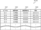
- such sensor information is stored in the TA sensor information storage unit 332 in a table format. More specifically, the terminal side sensor information table (TA sensor information table) ST-TA is registered in a sensor ID field 3321 for registering a sensor ID and the sensor ID field 3321 as shown in FIG. An installation location field 3322 for registering the location of the sensor device SU having the sensor ID being monitored, and a monitored person Ob (ie, monitored by the sensor device SU having the sensor ID registered in the sensor ID field 3321).
- TA sensor information table TA sensor information table
- the notification sound information storage unit 333 stores the notification sound information.
- the notification sound information is information related to the notification sound output from the TA sound input / output unit 34 when the event notification is received.
- the event includes a plurality of types of the predetermined action and nurse call, and the predetermined action also includes a plurality of awakening, getting out of bed, falling, and abnormal micromotion.
- the notification sound is set in advance according to the event type so that the event type can be audibly recognized by the notification sound. Therefore, more specifically, the notification sound information is information in which a plurality of different event types are associated with a plurality of different notification sounds according to the event type.
- such notification sound information is stored in the notification sound information storage unit 333 in a table format. More specifically, the notification sound information table TT is set in advance in accordance with, for example, an event field 3331 for registering an event type and an event type registered in the event field 3331 as shown in FIG. A notification sound field 3332 for registering the notified notification sound (notification sound data), and a record for each event type.
- the types of events are awakening, getting out of bed, falling, abnormal movement of the minute body, and nurse call. For this reason, in the example shown in FIG.
- the event field 3331 of each record contains wake-up, getting-off, falling, minute movement abnormality, and nurse call, respectively, and the notification sound field 3332 of each record includes each of them.
- Corresponding wake-up notification sound data Totetototote
- get-off notification sound data Popane Popain
- fall notification sound data Tin-Contin-Tin-Con
- separation body movement abnormality notification sound data B-B
- nurse call notification sound data Pico Pico
- the TA control processing unit 32 controls each part of the mobile terminal device TA according to the function of each part, receives and displays the monitoring information for the monitored person Ob, receives input of implementation intention information, It is a circuit for responding and calling out.
- the TA control processing unit 32 includes, for example, a CPU and its peripheral circuits.
- the TA control processing unit 32 executes a terminal processing unit (TA control unit) 321, a terminal side monitoring processing unit (TA monitoring processing unit) 322, a call processing unit 323, and a terminal side streaming process by executing a control processing program Unit (TA streaming processing unit) 324 functionally.
- the TA control unit 321 controls each part of the mobile terminal apparatus TA according to the function of each part, and controls the entire mobile terminal apparatus TA.
- the TA monitoring processing unit 322 executes predetermined information processing related to monitoring of the monitored person Ob. More specifically, when the TA monitoring processing unit 322 receives the second event notification communication signal transmitted by the management server device SV due to the first event notification communication signal transmitted by the sensor device SU. The monitoring information of the monitored person Ob is stored (recorded) in the TA monitoring information storage unit 331 based on each information (each data) accommodated in the received second event notification communication signal. The TA monitoring processing unit 322 displays a screen corresponding to each piece of information contained in the received second event notification communication signal on the TA display unit 36. Then, when receiving a predetermined input operation from the TA input unit 35, the TA monitoring processing unit 322 executes a predetermined process corresponding to the input operation.
- the TA monitoring processing unit 322 functionally includes a notification sound control unit 3221.
- the notification sound control unit 3221 outputs a predetermined notification sound from the TA sound input / output unit 34 when an event notification is received by the second event notification communication signal, and the notification sound is input to the TA sound input unit.
- the notification sound control unit 3221 receives an event notification by the second event notification communication signal
- the notification sound control unit 3221 displays a notification sound corresponding to the event type of the received notification as a notification sound information storage unit.
- the TA sound input / output unit 34 Based on the notification sound information stored in 333, the TA sound input / output unit 34 outputs a new event by a new second event notification communication signal while the notification sound is being output from the TA sound input / output unit 34. If the event type of the newly received notification is the same as the event type corresponding to the notification sound being output, the notification sound being output is continued. To do. On the other hand, the notification sound control unit 3221, when the event type of the newly received notification is not the same (different) as the event type corresponding to the notification sound being output, The notification sound is stopped, and a notification sound corresponding to the type of the newly received notification event is output from the TA sound input / output unit 34 based on the notification sound information. The notification sound control unit 3221 stops the notification sound being output when an input operation of a “corresponding” button 524 described later is received while the notification sound is being output from the TA sound input / output unit 34. .
- the notification sound control unit 3221 continuously outputs the notification sound from the TA sound input / output unit 34 for a predetermined first time. After the output of the notification sound is finished, the notification sound control unit 3221 Is output from the TA sound input / output unit.
- the reminder notification sound is preset with a melody different from the melody of the notification sound set according to the type of event.
- the TA monitoring processing unit 322 functionally counts the time from the start of notification sound output as necessary. , The first timer 3222 for measuring the first time is generated and deleted, and the second timer 3223 for measuring the second time is generated and deleted.
- the starting point of starting the time measurement in the second timer 3223 may be the time when the output of the notification sound is finished, but in the present embodiment, when the predetermined first time has elapsed from the time of the latest notification. is there. For this reason, as indicated by a broken line in FIG. 3, the TA monitoring processing unit 322 functionally starts counting from the time when the latest notification is received and counts the first time as necessary. Timer 3224 is created and deleted. Each of these first and second times is set to an appropriate arbitrary time length such as 30 seconds, 1 minute, 2 minutes, 5 minutes, and the like.
- notification priority is assigned to each of the plurality of different event types.
- the notification priority order is an order in which notification of an event for outputting a notification sound is determined from notification of a plurality of events when a notification of a plurality of events of different types is received.
- the nurse call has a high probability that the monitored person Ob requests the response (response) of the monitor (user), and therefore, the priority of notification in the nurse call is set to be the highest. ing.
- the priority levels of the remaining notifications other than the nurse call in the plurality of event types are set in the order of remind, fall, get out of bed, and wake up (nurse call> remind).
- the notification sound control unit 3221 receives a notification of a new event while outputting the notification sound from the TA sound input / output unit 34, the notification sound control unit 3221 corresponds to the priority order corresponding to the type of the event of the newly received notification. Is lower than the priority corresponding to the type of event corresponding to the notification sound being output, the notification sound being output is continued. On the other hand, when the notification sound control unit 3221 receives a notification of a new event while the notification sound is being output from the TA sound input / output unit 34, the notification sound control unit 3221 corresponds to the type of the newly received notification event.
- the notification sound being output is stopped, and the newly received event type of notification is received.
- a corresponding notification sound is output from the TA sound input / output unit based on the notification sound information.
- the call processing unit 323 performs a voice call with the sensor device SU by using the TA sound input / output unit 34 or the like. More specifically, for example, the call processing unit 323 transmits the first event notification communication signal that causes the transmission of the second event notification communication signal to the management server device SV using the TA sound input / output unit 34 or the like. For example, VoIP is performed with the transmission source sensor device SU.
- the TA streaming processing unit 324 receives the distribution of the moving image from the sensor device SU, and displays the distributed moving image on the TA display unit 36 by streaming reproduction.
- Such a portable terminal device TA can be configured by a portable communication terminal device such as a so-called tablet computer, a smartphone, or a mobile phone.
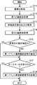
- FIG. 7 is a flowchart showing the operation of the sensor device shown in FIG.
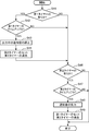
- FIG. 8 is a flowchart showing an operation related to the monitoring process in the mobile terminal device shown in FIG.
- FIG. 9 is a flowchart showing an operation related to the first output processing of the notification sound in the mobile terminal device shown in FIG.
- FIG. 10 is a flowchart showing an operation related to the second output processing of the notification sound in the portable terminal device shown in FIG.
- FIG. 11 is a flowchart showing an operation related to an input operation of a “corresponding” button in the mobile terminal device shown in FIG.
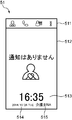
- FIG. 12 is a diagram showing an example of a standby screen displayed on the mobile terminal device shown in FIG.
- FIG. 13 is a diagram showing an example of a monitoring information screen displayed on the mobile terminal device shown in FIG.
- FIG. 14 is a diagram showing an example of a nurse call reception screen displayed on the mobile terminal device shown in FIG.
- each device SU, SV, SP, TA performs initialization of each necessary part and starts its operation when the power is turned on.
- the SU control processing unit 14 is functionally configured with a SU control unit 141, a behavior detection processing unit 142, a nurse call processing unit 143, and a SU streaming processing unit 144.
- the TA control processing unit 32 is functionally configured with a TA control unit 321, a TA monitoring processing unit 322, a call processing unit 323, and a TA streaming processing unit 324.
- the TA monitoring processing unit 322 is functionally configured with a notification sound control unit 3221 and, as will be described later, first to third timers 3222 to 3224 are configured and removed as necessary.
- the sensor device SU operates as follows for each frame or every several frames, thereby detecting a predetermined operation in the monitored person Ob and determining whether or not a nurse call is accepted.
- the sensor device SU acquires an image (image data) for one frame from the imaging unit 111 of the sensor unit 11 as the target image by the SU control unit 141 of the SU control processing unit 14 (S11). .
- the sensor device SU detects a first behavior that can be detected by the behavior detection processing unit 142 of the SU control processing unit 14 based on a target image among predetermined behaviors of the monitored person Ob. Is executed based on the target image acquired in the process S11, and the first detection result is stored in the SU storage unit 16 (S12).
- the first action is getting up, getting out of bed, and falling, and the action detection processing unit 142 determines whether or not to get up, determines whether or not to get out of bed, and determines whether or not to fall.
- the sensor device SU acquires the output of the body movement measurement unit 112 of the sensor unit 11 by the SU control unit 141 of the SU control processing unit 14 (S13).
- the sensor device SU detects the second behavior that can be detected based on the output of the body motion measurement unit 112 among the predetermined behaviors of the monitored person Ob by the behavior detection processing unit 142 of the SU control processing unit 14.
- the second action detection process is executed based on the output of the body movement measurement unit 112 acquired in the process S13, and the second detection result is stored in the SU storage unit 16 (S14).
- the second action is a minute movement abnormality
- the action detection processing unit 142 determines whether the minute movement abnormality is successful.
- the sensor device SU uses the behavior detection processing unit 142 based on the first detection result and the second detection result stored in the SU storage unit 16 in the processing S12 and the processing S14 to perform the predetermined detection in the monitored person Ob. It is determined whether or not an action has been detected (S15). As a result of the determination, when the predetermined action is not detected (No), the sensor device SU next executes the process S17, while when the predetermined action is detected (Yes). The sensor device SU executes the process S17 after executing the next process S16.
- the sensor device SU in order to notify the detected predetermined behavior to the predetermined terminal devices SP and TA via the management server device SV, the sensor device SU is used as the predetermined event by the behavior detection processing unit 142.
- a first event notification communication signal relating to detection of the predetermined action is transmitted to the management server device SV.
- the behavior detection processing unit 142 includes a sensor ID of the own device, event information (here, one or more of getting up, getting out of bed, falling, and abnormal micromotion) and a first event containing a target image.
- the notification communication signal is transmitted to the management server device SV via the SU communication IF unit 15.
- the sensor device SU determines whether the nurse call is accepted by the nurse call processing unit 143. That is, the processes S11 to S18 shown in FIG. 7 are repeatedly executed for each frame or every several frames, but during the period from the previous execution of the process S17 to the current execution of the process S17, It is determined whether or not the call reception operation unit 13 has been operated. As a result of this determination, when the nurse call reception operation unit 13 is not operated and the nurse call is not received (No), the sensor device SU ends the current process, while the nurse call reception operation unit 13 Is operated and the nurse call is accepted (Yes), the sensor device SU ends the current process after executing the next process S18.
- the sensor device SU uses the nurse call processing unit 143 to notify the predetermined terminal device SP, TA of the nurse call whose reception is found in the process S17 via the management server device SV.
- the first event notification communication signal related to the nurse call is transmitted to the management server device SV as the event. More specifically, the nurse call processing unit 143 sends a first event notification communication signal containing the sensor ID and event information (here, nurse call reception information) of the own device via the SU communication IF unit 15 to the management server. Send to device SV.
- the sensor device SU operates as described above with respect to each of detection of a predetermined action and reception of a nurse call in the monitored person Ob.
- the management server device SV When the management server device SV receives the first event notification communication signal from the sensor device SU via the network NW, the management server device SV receives monitoring information relating to monitoring of the monitored person Ob contained in the received first event notification communication signal. Remember (record). Then, the management server device SV transmits a second event notification communication signal to the notification destination terminal devices SP and TA corresponding to the sensor device SU that has transmitted the received first event notification communication signal. In the second event notification communication signal, the event information accommodated in the received first event notification communication signal is the predetermined action (one or more of awakening, getting out of bed, falling, and abnormal body movement).
- the sensor device SU having the sensor ID accommodated in the first event notification communication signal as the download destination of the sensor ID, the event information and the target image, and the moving image accommodated in the first event notification communication signal.
- the communication address to be stored is accommodated.
- the event information accommodated in the first event notification communication signal is nurse call reception information
- the sensor ID and the event information accommodated in the first event notification communication signal are included in the second event notification communication signal. Be contained.
- a predetermined action or nurse call in the monitored person Ob is notified from the sensor device SU to the terminal devices SP and TA via the management server device SV, and, for example, a nurse or a caregiver is transmitted via the terminal devices SP and TA.
- a supervisor (user) such as an expert is notified.
- the operation of the terminal devices SP and TA will be described.
- the operation of the mobile terminal device TA will be described.
- the portable terminal device TA accepts a login operation by a monitor (user) such as a nurse or a caregiver, and the TA monitor processing unit 322 automatically performs the login operation.
- a standby screen for waiting for a communication signal addressed to the machine is displayed on the TA display unit 36.
- the standby screen 51 includes a menu bar area 511 for displaying a menu bar, and a standby main area for displaying a message indicating standby (for example, “no notification”) and an icon.
- a time area 513 for displaying the current time a year / month / sunday area 514 for displaying the current year / month / sunday, and a user name area 515 for displaying the name of the user who is currently logged in to the portable terminal device TA.
- the portable terminal device TA determines whether or not the TA communication IF unit 31 has received a communication signal by the TA control unit 321 of the TA control processing unit 32 (S31). As a result of this determination, when the communication signal is not received (No), the mobile terminal device TA returns the process to S31, and as a result of the determination, when the communication signal is received (Yes), The portable terminal device TA executes the following process S32. That is, the mobile terminal device TA is waiting for reception of a communication signal.
- the portable terminal device TA determines the type of the received communication signal by the TA control unit 321. As a result of this determination, when the communication signal received in the process S31 is the second event notification communication signal (second event notification), the portable terminal device TA executes the next process S33, and in the process S31. When the received communication signal is not the second event notification communication signal (others), the process ends after executing the process S38 for performing an appropriate process according to the communication signal received in the process S31.
- the communication signal received in the process S31 is the second event notification communication signal (second event notification)
- the portable terminal device TA executes the next process S33, and in the process S31.
- the process ends after executing the process S38 for performing an appropriate process according to the communication signal received in the process S31.
- the mobile terminal device TA monitors the monitored person Ob contained in the second event notification communication signal received from the management server apparatus SV in the process S31 by the TA monitoring processing unit 322 of the TA control processing unit 32. Is stored (recorded) in the TA monitoring information storage unit 331.
- the TA monitoring processing unit 322 performs a first notification sound output process for outputting a predetermined notification sound from the TA sound input / output unit 34 by the notification sound control unit 3221.
- the notification sound control unit 3221 first determines whether or not a notification sound is output from the TA sound input / output unit 34 (S341). If the result of this determination is that a notification sound is being output (Yes, outputting), the notification sound control unit 3221 executes the next process S342, while the result of the determination is that a notification sound is being output. If not (No), the notification sound control unit 3221 executes the next process S345.
- the notification sound control unit 3221 determines the event type corresponding to the event information accommodated in the second event notification communication signal received in process S31, and the event type corresponding to the notification sound being output. It is determined whether or not is the same kind. Note that the type of event corresponding to the notification sound being output is recognized from the type of event stored in the TA storage unit 33 in association with the first timer 3222 as will be described later. If the result of this determination is the same type (Yes), the notification sound control unit 3221 executes the next process S344, while if the result of the determination is that it is not the same type (different) (No). The notification sound control unit 3221 executes the next process S343.
- the notification sound control unit 3221 determines that the notification priority given to the event type corresponding to the event information accommodated in the second event notification communication signal received in process S31 is the notification being output. It is determined whether or not the priority of the notification given to the event type corresponding to the sound is higher. If the result of this determination is high (Yes), the notification sound control unit 3221 executes the next process S346. On the other hand, if the result of the determination is not high (below), the notification sound control unit 3221 performs notification. The sound control unit 3221 executes the next process S344.
- the notification sound control unit 3221 continues the notification sound being output as it is. Therefore, when the event type corresponding to the event information accommodated in the second event notification communication signal received in step S31 is the same type as the event type corresponding to the notification sound being output, the output The notification sound inside is continued as it is.
- the notification given to the event type corresponding to the notification sound being output, the priority of the notification given to the event type corresponding to the event information accommodated in the second event notification communication signal received in step S31 If the priority order is lower than the priority order, the notification sound being output is continued as it is.
- the notification sound control unit 3221 deletes the existing third timer 3224, and again starts the third timer. 3224 is functionally formed in the TA monitoring processing unit 322, the time measurement is started (S345), this processing is terminated, and the processing S35 shown in FIG. 8 is executed.
- the notification sound control unit 3221 newly generates a notification sound corresponding to the event type corresponding to the event information accommodated in the second event notification communication signal received in the process S31 from the TA sound input / output unit 34. Output. More specifically, the notification sound control unit 3221 registers, in the event field 3331, the event type corresponding to the event information accommodated in the second event notification communication signal received in step S31 from the notification sound information table TT. A record to be selected is selected (searched), a notification sound (notification sound data) registered in the notification sound field 3333 of the selected record is extracted, and the extracted notification sound is newly output from the TA sound input / output unit 34.
- the notification sound data is only for one phrase
- the notification sound for one phrase is repeated while the notification sound is being output. Therefore, when the notification sound is not output, a notification sound is newly output.
- the notification sound control part 3221 performs the predetermined
- the TA monitoring processing unit 322 displays a screen corresponding to each piece of information contained in the second event notification communication signal received in step S31 on the TA display unit 36 (S35), and the next processing S36.
- the TA monitoring processing unit 322 for example, the monitoring information screen illustrated in FIG. 52 is displayed on the TA display unit 36.
- the event information accommodated in the second event notification communication signal received in the process S31 is the nurse call, for example, a nurse call reception screen 53 shown in FIG. Is displayed on the TA display unit 36.
- the monitoring information screen 52 is a screen for displaying the monitoring information related to the monitoring of the monitored person Ob.
- the monitoring information screen 52 includes a menu bar area 511, an arrangement location of the sensor device SU having the sensor ID accommodated in the second event notification communication signal received in the process S ⁇ b> 31, and the The monitored person name area 521 for displaying the name of the monitored person Ob monitored by the sensor device SU having the sensor ID, and the reception time of the second event notification communication signal received in the process S31 (or the predetermined action)
- a detection information display area 522 for displaying the elapsed time from the detection time) and the event information (the detection result of the predetermined action) contained in the second event notification communication signal received in the process S31;
- the image accommodated in the received second event notification communication signal that is, the pair imaged by the sensor device SU having the sensor ID).
- Image (here includes an image area 523 for displaying a still image), "corresponding" button 524, a "talk” button 525, a "Seed
- the sensor ID contained in the second event notification communication signal received in step S31 is used as a search key.
- the location of the device SU and the name of the monitored person Ob are retrieved from the TA sensor information storage unit 332 and displayed.
- the detection results in this embodiment, the names of getting up, getting out of bed, falling over, and abnormal movement of the micro body
- the detection result is displayed as an icon that symbolically represents the detection result.
- the TA storage unit 33 stores each action and an icon representative of the action in association with each other in advance.
- the detection information display area 522 displays a wake-up icon that symbolizes wake-up.
- the “corresponding” button 524 has an intention to perform a predetermined response (response, response) such as lifesaving, nursing, care, and assistance for the detection result displayed on the monitoring information screen 52. It is a button for inputting execution intention information indicating that the user of the mobile terminal device TA is present to the mobile terminal device TA.
- the “speak” button 525 is a button for requesting a voice call, and is used to input an instruction to connect the sensor device SU of the sensor ID and the mobile terminal device TA via the network NW. It is a button.
- the “LIVE” button 526 is a button for requesting a live video, and is a button for inputting an instruction to display a video captured by the sensor device SU of the sensor ID.
- the nurse call reception screen 53 is a screen for displaying reception of a nurse call.
- the nurse call reception screen 53 includes a menu bar area 511, a monitored person name area 521, a detection information display area 522, and a message (for example, “ Nurse call reception notification display area 531 for displaying “This is a nurse call”, a “corresponding” button 524, and a “speak” button 525.
- the detection information display area 522 displays only the elapsed time from the reception time of the second event notification communication signal received in step S31 (or the reception time of reception of the nurse call). .
- nurse call reception screen 53 may further include a “view LIVE” button 526.
- the portable terminal device TA determines whether or not the TA control processing unit 32 has accepted an input operation on the touch panel including the TA input unit 35 and the TA display unit 36. If the input operation is not accepted as a result of this determination (No), the mobile terminal device TA returns the process to step S36. On the other hand, if the input operation is accepted as a result of the determination, the mobile terminal The apparatus TA executes the next process S37.
- the portable terminal device TA performs an appropriate process according to the content of the input operation by the TA control processing unit 32, and ends this process.
- the mobile terminal device TA receives an input operation of the “corresponding” button 524 from the TA input unit 35 constituting the touch panel by the TA control processing unit 32 (that is, the intention to execute the correspondence) (S51), first, the monitoring information of the monitored person Ob currently displayed on the TA display unit 36 is added to the monitoring information Ob, indicating that “corresponding” has been received, and stored in the TA monitoring information storage unit 331. (S52). More specifically, the TA control processing unit 32 displays the current information on the TA display unit 36 in the TA monitoring information table MT-TA stored in the TA monitoring information storage unit 331 by the TA monitoring processing unit 322. In the correspondence field 3316 of the record in which the monitoring information of the monitored person Ob is registered (here, the record in which the monitoring information contained in the second event notification communication signal received in the processing S31 is registered) Corresponding flag “1” is registered.
- the TA control processing unit 32 indicates that the TA monitoring processing unit 322 has received the sensor ID corresponding to the monitoring information of the monitored person Ob displayed on the TA display unit 36 and “corresponding”.
- a communication signal (correspondence acceptance notification communication signal) containing (correspondence acceptance information) is transmitted to the management server device SV (S53).
- the management server device SV that has received the correspondence reception notification communication signal broadcasts the communication signal (correspondence reception well-known communication signal) containing the sensor ID and the correspondence reception information contained in the received correspondence reception notification communication signal. Transmit to the terminal devices SP and TA.
- the fact that “corresponding” has been received is synchronized between the terminal devices SP and TA.
- the TA control processing unit 32 determines whether or not the notification sound is output from the TA sound input / output unit 34 by the notification sound control unit 3221 of the TA monitoring processing unit 322 (S54). If the result of this determination is that a notification sound is being output (Yes, outputting), the notification sound control unit 3221 executes the next process S55, while the result of the determination is that a notification sound is being output. If not (No), the notification sound control unit 3221 executes the next process S57.
- the notification sound processing unit 3221 stops the notification sound being output.
- the notification sound being output is stopped by the input operation of the “corresponding” button 524.
- the TA input unit 35 constituting the touch panel corresponds to an example of a corresponding input unit that receives an input indicating that the user has an intention to perform a predetermined response to the received notification event.
- the notification sound processing unit 3221 deletes the first timer 3222 functionally generated in the TA monitoring processing unit 322 (S56), and executes the next processing S57.
- the notification sound processing unit 3221 erases the second timer 3223 functionally generated in the TA monitoring processing unit 322 as will be described later, and ends this process.
- the call processing unit 323 displays the object displayed on the TA display unit 36.
- a communication signal (call request communication signal) containing information such as requesting a voice call is transmitted to the sensor device SU that monitors the monitoring person Ob, and the voice call is made via the sensor device SU and the network NW according to the communication signal. Connect as possible. As a result, a voice call can be made between the mobile terminal device TA and the sensor device SU.
- the portable terminal device TA When the TA control processing unit 32 receives an input operation of an “end” button (not shown) that is a button for inputting an instruction to end a voice call, the portable terminal device TA causes the TA processing unit 323 to A communication signal (call end communication signal) containing information such as a request to end the voice call is transmitted to the sensor device SU that monitors the monitored person Ob displayed on the display unit 36. Thereby, the voice call between the mobile terminal device TA and the sensor device SU is terminated.
- an “end” button not shown
- a communication signal call end communication signal
- the TA streaming processing unit 324 displays the monitored object currently displayed on the TA display unit 36.
- a communication signal video distribution request communication signal
- the video is connected to be downloadable via the sensor device SU, receives live video distribution from the sensor device SU, and displays the distributed video on the TA display unit 36 by streaming playback.
- the “live end” button is a button for requesting the end of the moving image, and ends (stops) the distribution of the moving image picked up by the sensor device SU of the sensor ID and ends (stops) the display. This is a button for inputting an instruction to be performed.
- the TA control processing unit 32 receives an input operation of the “live end” button, the portable terminal device TA monitors the monitored person Ob currently displayed on the TA display unit 36 by the TA streaming processing unit 324.
- a communication signal (moving image distribution end communication signal) containing information such as requesting the end of moving image distribution is transmitted to the sensor device SU, and a still image is displayed on the TA display unit 36. Accordingly, the mobile terminal device TA ends the live video display.
- the mobile terminal device TA After accepting the login operation, the mobile terminal device TA performs notification sound stop processing and notification sound re-output processing (remind processing) shown in FIG. 10 by the notification sound control unit 3221 of the TA monitoring processing unit 322.
- the notification sound second output process is repeatedly executed.
- the notification sound control unit 3221 determines whether or not the first timer 3222 is functionally generated in the TA monitoring processing unit 322 (S41). If the result of this determination is that the first timer 3222 is present (Yes), the notification sound control unit 3221 executes the next process S42, while the result of this determination is that there is no first timer 3222 (No). The notification sound control unit 3221 executes the next process S46.
- the notification sound control unit 3221 determines whether or not the first timer 3222 has finished counting the first time and has timed up. If the result of this determination is that the first timer 3222 has timed up (Yes), the notification sound control unit 3221 executes the next process S43, while the result of this determination is that the first timer 3222 If not up (No), the notification sound control unit 3221 executes the next process S46.
- the notification sound control unit 3221 stops the notification sound being output. As a result, the notification sound being output is stopped as the first time elapses.
- the notification sound processing unit 3221 is associated with the type of event stored in the TA storage unit 33 in association with the first timer 3222 functionally generated in the TA monitoring processing unit 322.
- the second timer 3223 is functionally formed in the TA monitor processing unit 322.
- the third timer 3224 is not provided, the time is started.
- the third timer 3224 is provided, the third timer 3224 is up.
- the first timer 3222 functionally generated in the TA monitoring processor 322 is deleted (S44), and the next process S46 is executed. If the third timer 3224 is present, the third timer 3224 is deleted after the time is up.
- the starting point for starting the time measurement in the second timer 3223 is the time when the predetermined first time has elapsed from the time of the latest notification (the time of reception of the second event notification communication signal).
- the notification sound control unit 3221 determines whether or not the second timer 3223 is functionally generated in the TA monitoring processing unit 322. If the result of this determination is that the second timer 3223 is present (Yes), the notification sound control unit 3221 executes the next process S47, while the result of this determination is that there is no second timer 3223 (No). The notification sound control unit 3221 ends the current process.
- the notification sound control unit 3221 determines whether or not the second timer 3223 has finished counting the second time and has timed up. If the result of this determination is that the second timer 3223 has timed up (Yes), the notification sound control unit 3221 executes the next process S48, while the result of this determination is that the first timer 3222 has timed out. If not up (No), the notification sound control unit 3221 ends the current process.
- the notification sound control unit 3221 extracts the remind notification sound data stored in the notification sound information storage unit 333 of the TA storage unit 33, and outputs the remind notification sound from the TA sound input / output unit 34. Therefore, even if the notification sound ends when the first time elapses, if the input operation of the “corresponding” button 524 is not accepted for the notification, a remind notification sound is output after the second time elapses. Is done.
- the notification sound processing unit 3221 corresponds to the type of event stored in the TA storage unit 33 in association with the second timer 3222 that is functionally generated in the TA monitoring processing unit 322.
- the first timer 3223 is functionally formed in the TA monitoring processing unit 322, and the second timer 3222 that has been functionally generated in the TA monitoring processing unit 322 is deleted, and the current processing of this time is started. Exit.
- the mobile terminal device TA operates as described above.
- FIG. 15 is a state diagram showing a specific example for explaining the operation of the portable terminal device shown in FIG.
- the upper state C0 indicates the overall notification sound reproduction state in the mobile terminal device TA
- the lower states C1 to C7 indicate the state of the mobile terminal device TA at the time when each second event notification communication signal is received. Indicates the notification sound playback state.
- the mobile terminal device TA displays the standby screen 51 and receives a second event notification communication signal whose event information is awake at time T1
- the mobile terminal device TA performs processing S31, processing S32
- a wake-up notification sound (tutetotote 7) is output, and the processes S347, S35, and S36 of the process S34 are executed.
- Step S341, Step S342, Step S343, and Step S346 are executed to output a notification sound for getting out of bed (popeen popein 7), and Steps S347, S35, and S36 of Step S34 are executed. For this reason, the reminder notification sound for the wake-up notification sound is not output.
- step S341 step S342, step S343, and step S346, the fall notification sound (Tin Contin Contin.%) Is output, and Steps S347, S35, and S36 in Step S34 Execute. For this reason, the reminder notification sound for the notification sound of leaving the bed is not output.
- Step S31 processing S32, processing S33, and processing S34.
- Steps S341, S342, and S344 are executed to continuously output a fall notification sound (Tin-Contin-Tin-Contin 7), and Steps S345, S35, and S36 of Step S34 are performed. Execute. Accordingly, a third timer 3224 is generated for the second event notification communication signal received at time T4.
- each process shown in FIG. 10 is repeatedly executed, and at time T5, if the first timer 3222 has expired due to the elapse of the first time ⁇ T1 in process S42, the process falls over in process S43.
- step S44 after the time-up of the third timer 3224 due to the elapse of the first time ⁇ T1, the second timer 3223 starts measuring time and the first timer 3222 is deleted. Then, each process shown in FIG. 10 is repeatedly executed, and at time T7, when the second timer 3223 has timed up due to the elapse of the second time ⁇ T2 in process S47, a reminder notification sound is generated in process S48. Is output.
- the portable terminal device TA When the second event notification communication signal whose event information is a nurse call is received at time T8 during the output of the remind notification sound, the portable terminal device TA performs steps S31, S32, S33, and S34. By executing each of the processes S341, S342, S343, and S346, a nurse call notification sound (Pico Pico ...) is output, and processes S347, S35, and S36 of process S34 are executed.
- the portable terminal device TA performs processes S31, S32, S33, By executing the processes S341, S342, and S344 in the process S34, the nurse call notification sound Pico Pico is continuously output, and the processes S345, S35, and S36 of the process S34 are executed. . Therefore, a third timer 3224 is generated for the second event notification communication signal received at time T9.
- step S341 step S342, and step S344
- a remind notification sound is continuously output, and steps S345, S35, and S36 of step S34 are executed. Accordingly, a third timer 3224 is generated for the second event notification communication signal received at time T15.
- the portable terminal device TA operates, and in this example, a reminder notification sound is repeatedly output.
- the notification sound is a TA sound.
- the notification sound control unit 3221 that continues the notification sound being output is provided, so one phrase of the notification sound does not end Even if there is a new notification, a notification sound is not newly output from the beginning in response to the new notification.
- the notification sound control unit 3221 when notification of a nurse call is continuously notified, a notification sound is generated as in the case of a beeping beepy beep and the user (monitoring person)
- the notification sound control unit 3221 since the notification sound control unit 3221 is provided, even if the notification of the nurse call is continuously notified, like Pico Pico Pico Coop ... A notification tone sounds. Therefore, the monitored person monitoring system MS, the terminal devices SP, TA and the control method thereof can reduce annoyance and annoyance even when a new notification is received before one phrase of the notification sound is completed.
- the monitored person monitoring system MS, the terminal device SP, TA, and the control method thereof include a plurality of notification sounds different from each other according to the type of the event, Since the notification sound corresponding to the event type is output, the user can not only recognize the notification by hearing, but can also recognize the event type. Then, when the notification sound is being output from the sound output unit and the type of event of the newly received notification is the same as the type of event corresponding to the notification sound being output, the newly received notification Accordingly, even if a notification sound is newly output from the beginning, the user does not obtain new information in addition to the information obtained from the notification sound being output. I just feel it.
- the monitored person monitoring system MS, the terminal device SP, TA and the control method thereof are newly received when a notification of a new event is received while the notification sound is being output from the TA sound input / output unit 34.
- the notification sound control unit 3221 that continues the notification sound being output is provided. Even if there is a new notification before the end of one phrase, there is no meaning and no new notification sound is output from the beginning in response to the newly received notification, reducing the annoyance and annoyance it can.
- the notification sound controller 3221 outputs the notification sound corresponding to the type of the newly received notification event from the TA sound input / output unit 34 based on the notification sound information. Therefore, an event different from the event being notified can be notified to the user (monitor) by the notification sound.
- the monitored person monitoring system MS, the terminal devices SP and TA, and the control method thereof are configured to output a reminder notification sound from the sound output unit after a predetermined second time has elapsed after finishing outputting the notification sound. Since the sound control unit 3221 is provided, it is possible to prompt the user to deal with the event.
- the notification sound is being output from the sound output unit, and the priority corresponding to the type of the newly received notification event is being output. If the priority is lower than the priority corresponding to the type of event corresponding to the notification sound, the notification sound control unit 3221 that continues the notification sound being output is provided, so that notification of an event having a higher notification priority is provided. Can be maintained.
- the notification sound is being output from the sound output unit, and the priority corresponding to the type of the newly received notification event is being output. If it is higher than the priority corresponding to the type of event corresponding to the notification sound, the notification sound being output is stopped, and the notification sound corresponding to the type of the newly received notification event is displayed as the notification sound information. Since the notification sound control unit 3221 that outputs from the TA sound input / output unit 34 is provided based on the above, an event having a higher notification priority can be preferentially notified.
- the nurse call has a high probability that the monitored person Ob requests the monitoring person (user) to deal with, but the monitored person monitoring system MS, the terminal devices SP and TA, and the control method thereof are the nurse call. Since the priority order of notifications is the highest, notification of such nurse calls can be prioritized, and it becomes possible to promptly respond to the request of the monitored person Ob.
- the user When the user inputs an intention to perform a predetermined response to the received notification event, even if the notification sound is continued, the user has new information in addition to the information obtained from the continued notification sound. It is never obtained, and it just feels annoying with the above-mentioned harshness.
- the monitored person monitoring system MS, the terminal device SP, TA, and the control method thereof the notification sound being output when the notification sound is being output from the TA sound input / output unit 34 and the input of the intention is received. Since the notification sound control unit 3221 is stopped, the notification sound is meaningless without being continued, and the annoyance and annoyance can be reduced.
- the remind notification sound is a melody different from the notification sound according to the event type, but may be a notification sound according to the event type.
- the notification sound control unit 3221 continuously outputs the notification sound from the TA sound input / output unit 34 for a predetermined first time, and after outputting the notification sound, After the elapse of time, the TA notification input / output unit 34 outputs the completed notification sound.
- the type of event in the notification sound that has ended may be referred to the type of event stored in the TA storage unit 33 in association with the second timer 3223.
- a terminal device of a monitored person monitoring system is connected to the terminal device and the terminal device so as to be communicable, and detects a predetermined event related to a monitored person who is a monitoring target and transmits the event to the terminal device. It is the said terminal device of a monitoring person monitoring system provided with a monitoring person monitoring apparatus which notifies to.
- the terminal device includes a sound output unit that outputs a sound, and a notification sound control unit that outputs a notification sound from the sound output unit when a notification of the event is received, and the notification sound control unit includes the notification sound control unit, When a notification of a new event is received while a notification sound is being output from the sound output unit, the notification sound being output is continued.
- the predetermined event includes an event that needs to be dealt with.
- the predetermined event includes a predetermined action in the monitored person.
- the predetermined event includes a nurse call.
- the terminal device of such a monitored person monitoring system When the terminal device of such a monitored person monitoring system receives a notification of a new event (event) while outputting the notification sound from the sound output unit, the notification sound that continues the notification sound being output Since the control unit is provided, even if there is a new notification before one phrase of the notification sound is completed, the notification sound is not newly output from the beginning in response to the new notification. For this reason, the terminal device can reduce annoyance and annoyance even when there is a new notification before one phrase of the notification sound is completed.
- the event includes a plurality of types, a plurality of different event types, and a plurality of notification sounds that are different from each other according to the event type.
- a notification sound information storage unit that stores them as notification sound information in association with each other, and the notification sound control unit corresponds to the event type of the received notification when the notification of the event is received
- the notification sound is output from the sound output unit based on the notification sound information, and the notification sound is output from the sound output unit, a new event notification is received. If the type of event is the same as the type of event corresponding to the notification sound being output, the notification sound being output is continued.
- the terminal device of the monitored person monitoring system includes a plurality of notification sounds different from each other according to the type of the event, and the notification sound corresponding to the event type of the received notification Therefore, the user can recognize not only the notification by hearing but also the type of event.
- the notification sound is output from the sound output unit and the event type of the newly received notification is the same as the event type corresponding to the notification sound being output, the notification sound is received.
- the notification sound is newly output from the beginning, the user does not obtain new information in addition to the information obtained from the notification sound being output, and feels annoying and annoying as described above. It just ends up.
- the event type of the notification newly received is an event corresponding to the notification sound being output.
- a notification sound control unit that continues the notification sound being output is provided, so that even if a new notification is received before one phrase of the notification sound is completed, it is meaningless.
- the notification sound is not newly output from the beginning, and the annoyance and annoyance can be reduced.
- the notification sound control unit is configured such that a newly received event type corresponds to the event sound corresponding to the output notification sound. If they are not the same, the notification sound being output is stopped, and a notification sound corresponding to the type of the newly received notification event is output from the sound output unit based on the notification sound information.
- the terminal device of such a monitored person monitoring system when the event type of the newly received notification is not the same as the event type corresponding to the notification sound being output, Since a notification sound control unit that stops the notification sound and outputs a notification sound corresponding to the type of event of the newly received notification from the sound output unit based on the notification sound information, the notification sound is being notified. It is possible to notify the user of an event different from this event.
- the notification sound control unit continuously outputs the notification sound from the sound output unit for a predetermined first time, After the output ends, a reminder notification sound is output from the sound output unit after a predetermined second time has elapsed.
- the notification sound control unit sets a time when the predetermined first time has elapsed from the time of the notification received most recently as a starting point for measuring the predetermined second time.
- the terminal device of such a monitored person monitoring system includes a notification sound control unit that outputs a reminder notification sound from the sound output unit after a predetermined second time has elapsed after the output of the notification sound. The user can be prompted to deal with the event corresponding to the ended notification sound.
- each of the plurality of different event types has a priority of notification
- the notification sound control unit outputs the notification sound as the sound.
- the priority corresponding to the type of event of the newly received notification corresponds to the type of event corresponding to the notification sound being output. If it is lower than the priority, the notification sound being output is continued.
- the terminal device of such a monitored person monitoring system has an event in which the priority corresponding to the type of the newly received notification event corresponds to the notification sound being output while the notification sound is being output from the sound output unit. If the priority is lower than the priority corresponding to the type, the notification sound control unit that continues the notification sound being output is provided, so that notification of an event having a higher notification priority can be maintained.
- the notification sound control unit receives a new event notification while the notification sound is being output from the sound output unit. If the priority corresponding to the event type of the notification received is higher than the priority corresponding to the event type corresponding to the notification sound being output, the notification sound being output is stopped, A notification sound corresponding to the newly received event type is output from the sound output unit based on the notification sound information.
- the terminal device of such a monitored person monitoring system has an event in which the priority corresponding to the type of the newly received notification event corresponds to the notification sound being output while the notification sound is being output from the sound output unit.
- the notification sound being output is stopped, and the notification sound corresponding to the type of the newly received notification event is output based on the notification sound information. Since the notification sound control unit output from the unit is provided, an event having a higher notification priority can be preferentially notified.
- the plurality of event types include a nurse call, and the priority of notification in the nurse call is the highest.
- the terminal device of the above-described monitored person monitoring system further includes a response input unit that receives an input indicating that the user has an intention to perform a predetermined response to the received notification event,
- the notification sound control unit stops the notification sound being output when the notification sound is being output from the sound output unit and the input is received by the corresponding input unit.
- the terminal device includes a notification sound control unit that stops the notification sound being output when the notification sound is being output from the sound output unit and an input is received by the corresponding input unit, the terminal device is meaninglessly described above. The notification sound is not continued and the annoyance and annoyance can be reduced.
- a control method for a terminal device of a monitored person monitoring system wherein the terminal device is connected to the terminal device so as to be communicable and detects a predetermined event related to a monitored person to be monitored.
- a method for controlling the terminal device of a monitored person monitoring system comprising: a monitored person monitoring device that notifies an event to the terminal device.
- the terminal device control method includes: a notification receiving step for receiving notification of the event; and a notification sound control for outputting a notification sound from a sound output unit that outputs a sound when receiving the notification of the event in the notification receiving step.
- the notification sound control step continues the notification sound being output when the notification sound is being output from the sound output unit and a notification of a new event is received in the notification reception step.
- control method of such a terminal device includes a notification sound control step of continuing the notification sound being output when a notification of a new event is received while the notification sound is being output from the sound output unit, Even if there is a new notification before one phrase of the notification sound ends, the notification sound is not newly output from the beginning in response to the new notification. For this reason, the control method of the terminal device can reduce annoyance and annoyance even when a new notification is made before one phrase of the notification sound is completed.
- a monitored person monitoring system is connected to a terminal device and the terminal device so as to be communicable, detects a predetermined event relating to a monitored person who is a monitoring target, and transmits the event to the terminal device.
- a monitored person monitoring system comprising a monitored person monitoring apparatus for notification, wherein the terminal device is any one of the above-described terminal devices.
- Such a monitored person monitoring system uses any of the above-described terminal devices, so that it is possible to reduce annoyance and annoyance even when a new notification is received before one phrase of the notification sound is completed.
- a terminal device of a monitored person monitoring system it is possible to provide a terminal device of a monitored person monitoring system, a control method for the terminal device, and a monitored person monitoring system.
Landscapes
- Business, Economics & Management (AREA)
- Emergency Management (AREA)
- Physics & Mathematics (AREA)
- General Physics & Mathematics (AREA)
- Health & Medical Sciences (AREA)
- Life Sciences & Earth Sciences (AREA)
- Nursing (AREA)
- Animal Behavior & Ethology (AREA)
- General Health & Medical Sciences (AREA)
- Public Health (AREA)
- Veterinary Medicine (AREA)
- Accommodation For Nursing Or Treatment Tables (AREA)
- Alarm Systems (AREA)
- Measuring And Recording Apparatus For Diagnosis (AREA)
- Emergency Alarm Devices (AREA)
Abstract
本発明にかかる被監視者監視システムの端末装置およびその制御方法、ならびに、被監視者監視システムでは、監視対象である被監視者に関わる所定のイベントの通知を受けた場合に、通知音が出力され、この通知音を出力中に、新たなイベントの通知を受けた場合に、前記出力中の前記通知音が継続される。
Description
本発明は、被監視者を監視するための被監視者監視システムにおける端末装置および該端末装置の制御方法ならびに前記被監視者監視システムに関する。
我が国(日本)は、戦後の高度経済成長に伴う生活水準の向上、衛生環境の改善および医療水準の向上等によって、高齢化社会、より詳しくは、総人口に対する65歳以上の人口の割合である高齢化率が21%を超える超高齢化社会になっている。また、2005年では、総人口約1億2765万人に対し65歳以上の高齢者人口は、約2556万人であったのに対し、2020年では、総人口約1億2411万人に対し高齢者人口は、約3456万人となる予測もある。このような高齢化社会では、病気や怪我や高齢等による看護や介護を必要とする要看護者や要介護者(要看護者等)は、高齢化社会ではない通常の社会で生じる要看護者等よりもその増加が見込まれる。そして、我が国は、例えば2013年の合計特殊出生率が1.43という少子化社会でもある。そのため、高齢な要看護者等を高齢の家族(配偶者、子、兄弟)が介護する老老介護も起きて来ている。
要看護者等は、病院や、老人福祉施設(日本の法令では老人短期入所施設、養護老人ホームおよび特別養護老人ホーム等)等の施設に入所し、その看護や介護を受ける。このような施設では、要看護者等が、例えばベッドからの転落や歩行中の転倒等によって怪我を負ったり、ベッドから抜け出して徘徊したりするなどの事態が生じ得る。このような事態に対し、可及的速やかに対応する必要がある。また、このような事態を放置しておくとさらに重大な事態に発展してしまう可能性もある。このため、前記施設では、看護師や介護士等は、定期的に巡視することによってその安否や様子を確認している。
しかしながら、要看護者等の増加数に対し看護師等の増加数が追い付かずに、看護業界や介護業界では、慢性的に人手不足になっている。さらに、日勤の時間帯に較べ、準夜勤や夜勤の時間帯では、看護師や介護士等の人数が減るため、一人当たりの業務負荷が増大するので、前記業務負荷の軽減が要請される。また、前記老老介護の事態は、前記施設でも例外ではなく、高齢の要看護者等を高齢の看護師等がケアすることもしばしば見られる。一般に高齢になると体力が衰えるため、健康であっても若い看護師等に比し看護等の負担が重くなり、また、その動きや判断も遅くなる。
このような人手不足や看護師等の負担を軽減するため、看護業務や介護業務を補完する技術が求められている。このため、近年では、要看護者等の、監視すべき監視対象である被監視者を監視(モニタ)する被監視者監視技術が研究、開発されている。
このような技術の一つとして、例えば特許文献1に開示されたナースコールシステムがある。この特許文献1に開示されたナースコールシステムは、マット上に物体が乗ったことを検知して検知信号を出力するマットセンサと、上記マットセンサに接続され上記検知信号を入力したときに呼出信号を無線送信する送信機と、上記送信機から送信された呼出信号を受信してナースコール親機の呼び出しを行う受信機とを備えたナースコールシステムであって、上記送信機は、上記マットセンサから上記検知信号を入力したときに、ワンショットの呼出信号を上記受信機に送信し、その後所定時間が経過するまでは上記検知信号の入力があっても上記ワンショットの呼出信号を送信しないようにするワンショット呼出制御部と、上記ワンショット呼出制御部が上記ワンショットの呼出信号を送信してから上記所定時間が経過した時点で、上記検知信号の入力の有無を確認し、上記検知信号が入力されている場合に、連続した呼び出しを指示する連続呼出信号を上記受信機に送信する連続呼出制御部と、上記連続呼出制御部が上記連続呼出信号を送信した後、上記検知信号の入力の有無を確認し、上記検知信号が入力されなくなったときに、呼び出し復旧を指示する呼出復旧信号を上記受信機に送信する呼出復旧制御部とを備え、上記受信機は、上記ワンショットの呼出信号を受信したときに上記ナースコール親機の呼び出しをワンショットで行うとともに、上記連続呼出信号を受信したときに上記ナースコール親機の呼び出しを連続で行い、上記呼出復旧信号を受信したときに上記ナースコール親機の連続呼び出しを停止する呼出制御部を備える。より具体的には、前記特許文献1の[0036]段落によれば、患者によりマットセンサ1が踏まれている限り、最初にワンショットの呼出信号でナースコール親機6の呼び出しが行われ、それから所定時間を経過した後以降は連続呼び出しを指示する連続呼出信号でナースコール親機6の呼び出しが連続して行われる。また、連続呼出信号による呼び出しは、送信機から受信機に送信される呼出復旧信号により復旧される。そのため、連続した呼び出しが行われている際にナースコール親機6や廊下灯4で呼び出しを復旧する操作が行われたとしても、再びナースコール親機6の呼び出しが行われる結果、患者がマットセンサ1を踏まなくなるまではナースコール親機6での呼び出しの報知を継続させることができる。
一方、安否確認の点では、一人暮らしの独居者も前記要介護者等と同様であり、被監視対象者となる。
ところで、センサ装置の通知に応じて端末装置で通知音が出力されれば、ユーザは、センサ装置の前記通知を聴覚によって認識できるので、便利である。しかしながら、通知音の1フレーズが終了しないうちに、新たな通知があり、これに応じて通知音が最初から新たに出力されると、ユーザは、耳障りで、煩わしく感じてしまう。例えば、通知音の1フレーズが「プルルルー」である場合、通知音の1フレーズがそれぞれ終了しないうちに、4個のセンサ装置の通知があると、「プル、プ、プル、プルルルー」となり、ユーザは、耳障りで、煩わしく感じてしまう。
前記特許文献1には、呼出信号の制御について開示されているが、前記呼出信号に応じたナースコール親機での通知音の出力に関する開示はない。
本発明は、上述の事情に鑑みて為された発明であり、通知音の1フレーズが終了しないうちに、新たな通知があった場合でも、耳障りさや煩わしさを低減できる被監視者監視システムの端末装置および端末装置の制御方法ならびに被監視者監視システムを提供することである。
本発明にかかる被監視者監視システムの端末装置およびその制御方法、ならびに、被監視者監視システムでは、監視対象である被監視者に関わる所定のイベントの通知を受けた場合に、通知音が出力され、この通知音を出力中に、新たなイベントの通知を受けた場合に、前記出力中の前記通知音が継続される。したがって、本発明にかかる被監視者監視システムの端末装置およびその制御方法、ならびに、被監視者監視システムは、通知音の1フレーズが終了しないうちに、新たな通知があった場合でも、耳障りさや煩わしさを低減できる。
上記並びにその他の本発明の目的、特徴及び利点は、以下の詳細な記載と添付図面から明らかになるであろう。
以下、本発明にかかる実施の一形態を図面に基づいて説明する。なお、各図において同一の符号を付した構成は、同一の構成であることを示し、適宜、その説明を省略する。本明細書において、総称する場合には添え字を省略した参照符号で示し、個別の構成を指す場合には添え字を付した参照符号で示す。
実施形態における被監視者監視システムは、監視すべき(見守るべき)監視対象(見守り対象)である被監視者(見守り対象者)Obを複数の装置を用いて監視するシステムであり、端末装置と、前記端末装置と通信可能に接続され、被監視者Obに関わる所定のイベント(事象)を検知して前記イベントを前記端末装置へ通知する被監視者監視装置とを備える。前記端末装置は、音を出力する音出力部と、前記イベントの通知を受けた場合に、通知音を前記音出力部から出力する通知音制御部とを備える。そして、本実施形態では、前記通知音制御部は、前記通知音を前記音出力部から出力中に、新たなイベントの通知を受けた場合に、前記出力中の前記通知音を継続する。前記被監視者監視装置は、1個の装置で一体に構成されて良いが、本実施形態では、被監視者監視装置は、センサ装置と、前記センサ装置および前記端末装置それぞれと通信可能に接続される管理サーバ装置(中央処理装置)とを備えることで、2種類の各装置で別体に構成される。このセンサ装置は、被監視者Obに関わる前記所定のイベントを検知して前記管理サーバ装置へ通知(報知、送信)する。前記管理サーバ装置は、前記センサ装置から前記通知を受けると、前記通知を受けた前記イベントを管理するとともに前記イベントを前記センサ装置に対応付けられた所定の端末装置へ再通知(再報知、再送信)する。前記端末装置は、1種類の装置であって良いが、本実施形態態では、前記端末装置は、固定端末装置と携帯端末装置との2種類の装置である。これら固定端末装置と携帯端末装置との主な相違は、固定端末装置が固定的に運用される一方、携帯端末装置が例えば看護師や介護士等の監視者(ユーザ)に携行されて運用される点であり、これら固定端末装置と携帯端末装置とは、略同様であるので、以下の実施形態では、携帯端末装置を主に説明する。
図1は、実施形態における被監視者監視システムの構成を示す図である。図2は、図1に示す前記被監視者監視システムにおけるセンサ装置の構成を示す図である。図3は、図1に示す被監視者監視システムにおける携帯端末装置の構成を示す図である。図4は、図3に示す前記携帯端末装置に記憶される監視情報テーブルの構成を示す図である。図5は、図3に示す前記携帯端末装置に記憶されるセンサ情報テーブルの構成を示す図である。図6は、図3に示す前記携帯端末装置に記憶される通知音情報テーブルの構成を示す図である。
このような被監視者監視システムMSは、より具体的には、例えば、図1に示すように、1または複数のセンサ装置SU(SU-1~SU-4)と、管理サーバ装置SVと、固定端末装置SPと、1または複数の携帯端末装置TA(TA-1、TA-2)とを備え、これらは、有線や無線で、LAN(Local Area Network)、電話網およびデータ通信網等の網(ネットワーク、通信回線)NWを介して通信可能に接続される。ネットワークNWには、通信信号を中継する例えばリピーター、ブリッジ、ルーターおよびクロスコネクト等の中継機が備えられても良い。図1に示す例では、これら複数のセンサ装置SU-1~SU-4、管理サーバ装置SV、固定端末装置SPおよび複数の携帯端末装置TA-1、TA-2は、アクセスポイントAPを含む無線LAN(例えばIEEE802.11規格に従ったLAN等)NWによって互いに通信可能に接続されている。
被監視者監視システムMSは、被監視者Obに応じて適宜な場所に配設される。被監視者(見守り対象者)Obは、例えば、病気や怪我等によって看護を必要とする者や、身体能力の低下等によって介護を必要とする者や、一人暮らしの独居者等である。特に、早期発見と早期対処とを可能にする観点から、被監視者Obは、例えば異常状態等の所定の不都合な事象がその者に生じた場合にその発見を必要としている者であることが好ましい。このため、被監視者監視システムMSは、被監視者Obの種類に応じて、病院、老人福祉施設および住戸等の建物に好適に配設される。図1に示す例では、被監視者監視システムMSは、複数の被監視者Obが入居する複数の居室RMや、ナースステーション等の複数の部屋を備える介護施設の建物に配設されている。
センサ装置SUは、ネットワークNWを介して他の装置SV、SP、TAと通信する通信機能等を備え、被監視者Obに関わる所定のイベントを検知してこの検知した前記イベントを管理サーバ装置SVへ通知し、端末装置SP、TAとの間で音声通話を行い、そして、動画を含む画像を生成して端末装置SP、TAへ動画を配信する装置である。前記所定のイベント(事象)は、好ましくは、対処(対応)が必要なイベントを含む。本実施形態では、前記所定のイベントは、被監視者Obにおける、予め設定された所定の行動を含み、ナースコールを含む。このようなセンサ装置SUは、例えば、図2に示すように、センサ部11と、センサ側音入出力部(SU音入出力部)12と、ナースコール受付操作部13と、センサ側制御処理部(SU制御処理部)14と、センサ側通信インターフェース部(SU通信IF部)15と、センサ側記憶部(SU記憶部)16とを備える。
センサ部11は、SU制御処理部14に接続され、SU制御処理部14の制御に従って、被監視者Obにおける予め設定された所定の諸量を検出する装置である。前記所定の諸量は、被監視者Obにおける検知すべき所定の行動に応じて適宜に決定される。本実施形態では、前記所定の行動は、例えば、被監視者Obが起きた起床、被監視者Obが寝具から離れた離床、被監視者Obが倒れた転倒、および、被監視者Obの体動が異常である微体動異常の4つの行動であり、これらを検知するために、センサ部11は、例えば、撮像部111と、体動測定部112とを備える。なお、前記所定の行動には、被監視者Obが寝具から落ちた転落がさらに含まれても良い。
撮像部111は、SU制御処理部14に接続され、SU制御処理部14の制御に従って、画像(画像データ)を生成する装置である。前記画像には、静止画(静止画データ)および動画(動画データ)が含まれる。撮像部111は、被監視者Obが所在を予定している空間(所在空間、図1に示す例では配設場所の居室RM)を監視可能に配置され、前記所在空間を撮像対象としてその上方から撮像し、前記撮像対象を俯瞰した画像(画像データ)を生成し、前記撮像対象の画像(対象画像)をSU制御処理部14へ出力する。好ましくは、被監視者Ob全体を撮像できる蓋然性が高いことから、撮像部111は、被監視者Obが横臥する寝具(例えばベッド等)における、被監視者Obの頭部が位置すると予定されている予め設定された頭部予定位置(通常、枕の配設位置)の直上から撮像対象を撮像できるように配設される。センサ装置SUは、この撮像部111によって、被監視者Obを、被監視者Obの上方から撮像した画像、好ましくは前記頭部予定位置の直上から撮像した画像を取得する。
このような撮像部111は、可視光の画像を生成する装置であって良いが、比較的暗がりでも被監視者Obを監視できるように、本実施形態では、赤外線の画像を生成する装置である。このような撮像部111は、例えば、本実施形態では、撮像対象における赤外の光学像を所定の結像面上に結像する結像光学系、前記結像面に受光面を一致させて配置され、前記撮像対象における赤外の光学像を電気的な信号に変換するイメージセンサ、および、イメージセンサの出力を画像処理することで前記撮像対象における赤外の画像を表すデータである画像データを生成する画像処理部等を備えるデジタル赤外線カメラである。撮像部111の前記結像光学系は、本実施形態では、その配設された居室RM全体を撮像できる画角を持つ広角な光学系(いわゆる広角レンズ(魚眼レンズを含む))であることが好ましい。
体動測定部112は、SU制御処理部14に接続され、SU制御処理部14の制御に従って、被監視者Obにおける所定の体動を測定する装置である。前記所定の体動は、本実施形態では、呼吸に伴う胸部の体表の動きであり、このため、体動測定部112は、例えば、ドップラセンサを備えて構成される。このドップラセンサは、送信波を送信し、物体で反射した前記送信波の反射波を受信し、前記送信波と前記反射波とに基づいてドップラ周波数成分のドップラ信号を出力する体動センサである。前記物体が動いている場合、いわゆるドップラ効果により前記物体の動いている速度に比例して反射波の周波数がシフトするため、送信波の周波数と反射波の周波数とに差(ドップラ周波数成分)が生じる。前記ドップラセンサは、このドップラ周波数成分の信号をドップラ信号として生成し、SU制御処理部14へ出力する。前記送信波は、超音波やマイクロ波等であって良いが、本実施形態では、マイクロ波である。マイクロ波は、着衣を透過して被監視者Obの体表で反射できるため、被監視者Obが衣服を着ていても体表の動きを検知でき、好ましい。
SU音入出力部12は、SU制御処理部14に接続され、外部の音を取得してセンサ装置SUに入力するための回路であって、SU制御処理部14の制御に従って音を表す電気信号に応じた音を生成して出力するための回路である。SU音入出力部12は、例えば、音の音響振動を電気信号に変換するマイクロホン等と、音の電気信号を音の音響振動に変換するスピーカ等とを備えて構成される。SU音入出力部12は、外部の音を表す電気信号をSU制御処理部14へ出力し、SU制御処理部14から入力された電気信号を音の音響振動に変換して出力する。
ナースコール受付操作部13は、SU制御処理部14に接続され、ナースコールを当該センサ装置SUに入力するための例えば押しボタン式スイッチ等のスイッチ回路である。なお、ナースコール受付操作部13は、有線でSU制御処理部14に接続されて良く、また、例えばBluetooth(登録商標)規格等の近距離無線通信でSU制御処理部14に接続されて良い。
SU通信IF部15は、SU制御処理部14に接続され、SU制御処理部14の制御に従って通信を行うための通信回路である。SU通信IF部15は、SU制御処理部14から入力された転送すべきデータを収容した通信信号を、この被監視者監視システムMSのネットワークNWで用いられる通信プロトコルに従って生成し、この生成した通信信号をネットワークNWを介して他の装置SV、SP、TAへ送信する。SU通信IF部15は、ネットワークNWを介して他の装置SV、SP、TAから通信信号を受信し、この受信した通信信号からデータを取り出し、この取り出したデータをSU制御処理部14が処理可能な形式のデータに変換してSU制御処理部14へ出力する。SU通信IF部15は、例えば、IEEE802.11規格等に従った通信インターフェース回路を備えて構成される。
SU記憶部16は、SU制御処理部14に接続され、SU制御処理部14の制御に従って、各種の所定のプログラムおよび各種の所定のデータを記憶する回路である。前記各種の所定のプログラムには、例えば、センサ装置SUの各部を当該各部の機能に応じてそれぞれ制御するSU制御プログラムや、センサ部11の出力に基づいて被監視者Obにおける所定の行動を検知して管理サーバ装置SVへ通知する行動検知処理プログラムや、ナースコール受付操作部13でナースコールを受け付けた場合にその旨を管理サーバ装置SVへ通知し、SU音入出力部12等を用いることで端末装置SP、TAとの間で音声通話を行うナースコール処理プログラムや、撮像部111で生成した動画を、その動画を要求した端末装置SP、TAへストリーミングで配信するSUストリーミング処理プログラム等の制御処理プログラムが含まれる。前記各種の所定のデータには、自機の、センサ装置SUを特定し識別するための識別子であるセンサ装置識別子(センサID)、および、管理サーバ装置SVの通信アドレス等の各プログラムを実行する上で必要なデータ等が含まれる。SU記憶部16は、例えば不揮発性の記憶素子であるROM(Read Only Memory)や書き換え可能な不揮発性の記憶素子であるEEPROM(Electrically Erasable Programmable Read Only Memory)等を備える。そして、SU記憶部16は、前記所定のプログラムの実行中に生じるデータ等を記憶するいわゆるSU制御処理部14のワーキングメモリとなるRAM(Random Access Memory)等を含む。
SU制御処理部14は、センサ装置SUの各部を当該各部の機能に応じてそれぞれ制御し、被監視者Obに関わる所定のイベントを検知してこの検知した前記イベントを管理サーバ装置SVへ通知し、端末装置SP、TAとの間で音声通話を行い、そして、動画を含む画像を生成して端末装置SP、TAへ動画を配信するための回路である。SU制御処理部14は、例えば、CPU(Central Processing Unit)およびその周辺回路を備えて構成される。SU制御処理部14は、前記制御処理プログラムが実行されることによって、センサ側制御部(SU制御部)141、行動検知処理部142、ナースコール処理部143およびセンサ側ストリーミング処理部(SUストリーミング処理部)144を機能的に備える。
SU制御部141は、センサ装置SUの各部を当該各部の機能に応じてそれぞれ制御し、センサ装置SUの全体制御を司るものである。
行動検知処理部142は、センサ部11の出力に基づいて、被監視者Obにおける、予め設定された所定の行動を検知して管理サーバ装置SVへ通知するものである。より具体的には、本実施形態では、前記所定の行動は、上述したように、起床、離床、転倒および微体動異常である。これら起床、離床および転倒は、撮像部111の出力(対象画像)に基づいて検知され、前記微体動異常は、体動測定部112の出力(ドップラ信号)に基づいて検知される。より具体的には、行動検知処理部142は、例えば、撮像部11で撮像した対象画像に基づいて被監視者Obの頭部を検出し、この検出した被監視者Obの頭部における大きさの時間変化に基づいて被監視者Obの起床、離床および転倒を検知する。より詳しくは、まず、寝具BTの所在領域、および、第1ないし第3閾値Th1~Th3が前記各種の所定のデータの1つとして予めSU記憶部16が記憶される。前記第1閾値Th1は、寝具BTの所在領域内における横臥姿勢の頭部の大きさと座位姿勢の頭部の大きさとを識別するための値である。前記第2閾値Th2は、寝具BTの所在領域を除く居室RM内における立位姿勢の頭部の大きさであるか否かを識別するための値である。前記第3閾値Th3は、寝具BTの所在領域を除く居室RM内における横臥姿勢の頭部の大きさであるか否かを識別するための値である。そして、行動検知処理部142は、対象画像から例えば背景差分法やフレーム差分法によって被監視者Obの人体領域として動体領域を抽出する。次に、行動検知処理部142は、この抽出した動体領域から、例えば円形や楕円形のハフ変換によって、また例えば予め用意された頭部のモデルを用いたパターンマッチングによって、また例えば頭部検出用に学習したニューラルネットワークによって、被監視者Obの頭部領域を抽出する。そして、行動検知処理部142は、この抽出した頭部の位置および大きさから起床、離床および転倒を検知する。例えば、行動検知処理部142は、この抽出した頭部の位置が寝具BTの所在領域内であって、前記抽出した頭部の大きさが前記第1閾値Th1を用いることによって横臥姿勢の大きさから座位姿勢の大きさへ時間変化した場合には、起床と判定し、前記起床を検知する。例えば、行動検知処理部142は、この抽出した頭部の位置が寝具BTの所在領域内から寝具BTの所在領域外へ時間変化した場合であって、前記抽出した頭部の大きさが前記第2閾値Th2を用いることによって或る大きさから立位姿勢の大きさへ時間変化した場合には、離床と判定し、前記離床を検知する。例えば、行動検知処理部142は、この抽出した頭部の位置が寝具BTの所在領域を除く居室RM内であって、前記抽出した頭部の大きさが前記第3閾値Th1を用いることによって或る大きさから横臥姿勢の大きさへ時間変化した場合には、転倒と判定し、前記転倒を検知する。なお、転落を検知する場合には、例えば、行動検知処理部142は、この抽出した頭部の位置が寝具BTの所在領域内から寝具BTの所在領域外へ時間変化した場合であって、前記抽出した頭部の大きさが前記第3閾値Th3を用いることによって或る大きさから横臥姿勢の大きさへ時間変化した場合には、転落と判定し、前記転落を検知する。そして、行動検知処理部142は、体動測定部112の出力によって被監視者Obの呼吸動作に伴う胸部の体表の動き(胸部の上下動)を検出し、その胸部の体表の動きにおける周期の乱れや、予め設定された閾値以下である、前記胸部の体表の動きにおける振幅を検知すると、前記微体動異常と判定し、微体動異常を検知する。
このように前記所定の行動を検知すると、行動検知処理部142は、被監視者Obに関わる所定のイベント(事象)の内容を表すイベント情報(事象情報)を収容した、前記イベントを通知するための第1イベント通知通信信号をSU通信IF部15で管理サーバ装置SVへ通知する。より詳しくは、行動検知処理部142は、自機のセンサID、前記イベントの内容を表すイベント情報、前記起床、離床および転倒の検知の際に用いられた対象画像を収容した通信信号(第1イベント通知通信信号)を、SU通信IF部15を介して管理サーバ装置SVへ送信する。前記イベント情報は、本実施形態では、起床、離床、転倒、微体動異常およびナースコール(NC)のうちの1または複数であり、ここでは、行動検知処理部142は、検知した起床、離床、転倒および微体動異常のうちの1または複数を前記イベント情報として第1イベント通知通信信号に収容する。前記画像は、静止画および動画のうちの少なくとも一方であって良く、本実施形態では、後述するように、まず、静止画が報知され、ユーザの要求に応じて動画が配信される。なお、まず、動画が配信されても良く、また、静止画および動画が送信され、画面分割で静止画および動画が端末装置SP、TAに表示されても良い。
ナースコール処理部143は、ナースコール受付操作部13でナースコールを受け付けた場合にその旨を前記所定のイベントの他の一例として収容した第1イベント通知通信信号を管理サーバ装置SVへ通知し、SU音入出力部12等を用いることで端末装置SP、TAとの間で音声通話を行うものである。より具体的には、ナースコール処理部143は、ナースコール受付操作部13が入力操作されると、自機のセンサIDおよび前記イベント情報としてナースコールを収容した第1イベント通知通信信号をSU通信IF部15を介して管理サーバ装置SVへ送信する。ナースコール処理部143は、SU音入出力部12等を用い、端末装置SP、TAとの間で例えばVoIP(Voice over Internet Protocol)によって音声通話を行う。
SUストリーミング処理部144は、通信IF部3を介して固定端末装置SPまたは携帯端末装置TAから動画の配信の要求があった場合に、この要求のあった固定端末装置SPまたは携帯端末装置TAへ、撮像部11で生成した動画(例えばライブの動画)をストリーミング再生でSU通信IF部15を介して配信するものである。
図1には、一例として、4個の第1ないし第4センサ装置SU-1~SU-4が示されており、第1センサ装置SU-1は、被監視者Obの一人であるAさんOb-1の居室RM-1(不図示)に配設され、第2センサ装置SU-2は、被監視者Obの一人であるBさんOb-2の居室RM-2(不図示)に配設され、第3センサ装置SU-3は、被監視者Obの一人であるCさんOb-3の居室RM-3(不図示)に配設され、そして、第4センサ装置SU-4は、被監視者Obの一人であるDさんOb-4の居室RM-4(不図示)に配設されている。
管理サーバ装置SVは、ネットワークNWを介して他の装置SU、SP、TAと通信する通信機能等を備え、センサ装置SUから、被監視者Obに関わる所定のイベントの通知を受信すると被監視者Obに対する監視に関する情報(監視情報)を管理する装置である。管理サーバ装置SVは、センサ装置SUから前記イベントの通知として第1イベント通知通信信号を受信すると、前記第1イベント通知通信信号に収容された各情報に基づいて、被監視者Obに対する監視に関する前記監視情報を記憶(記録)し、そして、被監視者Obに対する監視に関する前記監視情報を収容した通信信号(第2イベント通知通信信号)を、前記センサ装置SUに予め対応付けられた所定の端末装置SP、TAに送信する。このために、管理サーバ装置SVは、センサ装置SUから送信された第1イベント通知通信信号等の通知先(再通知先、再報知先、送信先)を示す、送信元であるセンサIDと通知先(再通知先)である端末IDとの対応関係(通知先対応関係)、および、その通信アドレスを記憶する。端末ID(端末装置識別子)は、端末装置SP、TAを特定し識別するための識別子である。前記第2イベント通知通信信号には、前記第1イベント通知通信信号に収容されたイベント情報が前記所定の行動(起床、離床、転倒および微体動異常のうちの1または複数)である場合には、第1イベント通知通信信号に収容されたセンサID、イベント情報および対象画像、ならびに、動画のダウンロード先として、第1イベント通知通信信号に収容されたセンサIDを持つセンサ装置SUに対応する通信アドレスが収容される。前記第1イベント通知通信信号に収容されたイベント情報がナースコール受付情報である場合には、前記第2イベント通知通信信号には、第1イベント通知通信信号に収容されたセンサIDおよびイベント情報が収容される。管理サーバ装置SVは、クライアント(本実施形態では固定端末装置SPおよび携帯端末装置TA等)の要求に応じたデータを前記クライアントに提供する。このような管理サーバ装置SVは、例えば、通信機能付きのコンピュータによって構成可能である。
固定端末装置SPは、ネットワークNWを介して他の装置SU、SV、TAと通信する通信機能、所定の情報を表示する表示機能、および、所定の指示やデータを入力する入力機能等を備え、管理サーバ装置SVや携帯端末装置TAに与える所定の指示やデータを入力したり、センサ装置SUで得られた監視情報を表示したり等することによって、被監視者監視システムMSのユーザインターフェース(UI)として機能する装置である。このような固定端末装置SPは、例えば、通信機能付きのコンピュータによって構成可能である。なお、前記端末装置の一例としての固定端末装置SPは、携帯端末装置TAと同様に動作するが、本明細書では、前記端末装置の他の一例である携帯端末装置TAについて説明される。
携帯端末装置TAは、ネットワークNWを介して他の装置SV、SP、SUと通信する通信機能、所定の情報を表示する表示機能、所定の指示やデータを入力する入力機能、および、音声通話を行う通話機能等を備え、管理サーバ装置SVやセンサ装置SUに与える所定の指示やデータを入力したり、管理サーバ装置SVからの通知によってセンサ装置SUで得られた監視情報(動画を含む)を表示したり、センサ装置SUとの間で音声通話によってナースコールの応答や声かけしたり等するための機器である。そして、本実施形態では、携帯端末装置TAは、センサ装置SUから管理サーバ装置SVを介して第2イベント通知通信信号によってイベントの通知を受けた場合に所定の通知音を出力し、この通知音の出力中に、新たなイベントの通知を受けた場合に、前記新たなイベントの通知に基づき前記出力中の前記通知音を継続する。このような携帯端末装置TAは、本実施形態では、例えば、図3に示すように、端末側通信インターフェース部(TA通信IF部)31と、端末側制御処理部(TA制御処理部)32と、端末側記憶部(TA記憶部)33と、端末側音入出力部(TA音入出力部)34と、端末側入力部(TA入力部)35と、端末側表示部(TA表示部)36と、端末側インターフェース部(TAIF部)37とを備える。
TA音入出力部34は、TA制御処理部32に接続され、外部の音を取得して携帯端末装置TAに入力するための回路であって、TA制御処理部32の制御に従って音を表す電気信号に応じた音を生成して出力するための回路である。TA音入出力部34は、SU音入出力部12と同様に、例えば、音響振動を電気信号に変換するマイクロホン等と、音の電気信号を音の音響振動に変換するスピーカ等とを備えて構成される。TA音入出力部34は、外部の音を表す電気信号をTA制御処理部32へ出力し、TA制御処理部32から入力された電気信号を音の音響振動に変換して出力する。
TA入力部35は、TA制御処理部32に接続され、例えば、所定の操作を受け付け、携帯端末装置TAに入力する回路であり、例えば、所定の機能を割り付けられた複数の入力スイッチ等である。前記所定の操作には、例えば、ログインするためのIDの入力操作や、音声通話の要求操作およびその終了操作や、ライブでの動画の要求操作およびその終了操作や、前記通知された被監視者Obに対する前記イベントの検知結果に対応(対処)する意思がある旨(実施意思情報)の入力操作等の、監視する上で必要な各種操作等が含まれる。TA表示部36は、TA制御処理部32に接続され、TA制御処理部32の制御に従って、TA入力部35から入力された所定の操作内容や、被監視者監視システムMSによって監視されている被監視者Obに対する監視に関する前記監視情報(例えばセンサ装置SUで検知した所定の行動の種類や被監視者Obの画像(静止画および動画)等)や、ナースコールの受付等を表示する回路であり、例えばLCD(液晶ディスプレイ)および有機ELディスプレイ等の表示装置である。そして、本実施形態では、TA入力部35およびTA表示部36からタッチパネルが構成されている。この場合において、TA入力部35は、例えば抵抗膜方式や静電容量方式等の操作位置を検出して入力する位置入力デバイスである。このタッチパネルでは、TA表示部36の表示面上に位置入力デバイスが設けられ、TA表示部36に入力可能な1または複数の入力内容の候補が表示され、例えば看護師や介護士等のユーザ(監視者)が、入力したい入力内容を表示した表示位置を触れると、位置入力デバイスによってその位置が検出され、検出された位置に表示された表示内容がユーザの操作入力内容として携帯端末装置TAに入力される。
TAIF部37は、TA制御処理部32に接続され、TA制御処理部32の制御に従って、外部機器との間でデータの入出力を行う回路であり、例えば、Bluetooth(登録商標)規格を用いたインターフェース回路、IrDA規格等の赤外線通信を行うインターフェース回路、および、USB規格を用いたインターフェース回路等である。
TA通信IF部31は、SU通信IF部15と同様に、TA制御処理部32に接続され、TA制御処理部32の制御に従って通信を行うための通信回路である。TA通信IF部31は、TA制御処理部32から入力された転送すべきデータを収容した通信信号を、この被監視者監視システムMSのネットワークNWで用いられる通信プロトコルに従って生成し、この生成した通信信号をネットワークNWを介して他の装置SU、SV、SPへ送信する。TA通信IF部31は、ネットワークNWを介して他の装置SU、SV、SPから通信信号を受信し、この受信した通信信号からデータを取り出し、この取り出したデータをTA制御処理部32が処理可能な形式のデータに変換してTA制御処理部32へ出力する。TA通信IF部31は、例えば、IEEE802.11規格等に従った通信インターフェース回路を備えて構成される。
TA記憶部33は、TA制御処理部32に接続され、TA制御処理部32の制御に従って、各種の所定のプログラムおよび各種の所定のデータを記憶する回路である。前記各種の所定のプログラムには、例えば、携帯端末装置TAの各部を当該各部の機能に応じてそれぞれ制御するTA制御プログラムや、被監視者Obに対する監視に関する所定の情報処理を実行するTA監視処理プログラムや、TA音入出力部34等を用いることでセンサ装置SUとの間で音声通話を行う通話処理プログラムや、センサ装置SUから動画の配信を受け、前記配信を受けた動画をストリーミング再生でTA表示部36に表示するTAストリーミング処理プログラム等の制御処理プログラムが含まれる。前記TA監視処理プログラムには、管理サーバ装置SVからイベントの通知を受信すると被監視者Obに対する監視に関する情報(監視情報)をTA記憶部33に記憶(記録)するログプログラムや、前記イベントの通知を受けた場合に、前記通知を受けたイベントの種類に応じた通知音をTA音入出力部34から出力する通知音制御プログラムや、前記監視情報をTA表示部36に表示する表示制御プログラム等の各種プログラムが含まれる。前記各種の所定のデータでは、自機の端末ID、TA表示部36に表示される画面情報、被監視者Obに対する監視に関する前記監視情報、センサ装置SUに関するセンサ情報、前記イベントの通知を受けた場合にTA音入出力部から出力される通知音に関する通知音情報等の各プログラムを実行する上で必要なデータ等が含まれる。これら監視情報、センサ情報および通知音情報それぞれを記憶するために、TA記憶部33は、端末側監視情報記憶部(TA監視情報記憶部)331、端末側センサ情報記憶部(TAセンサ情報記憶部)332および通知音情報333を機能的に備える。
TA監視情報記憶部331は、前記監視情報として、本実施形態では、管理サーバ装置SVから受信した第2イベント通知通信信号に収容されたセンサID、イベント情報(本実施形態では起床、離床、転倒、微体動異常およびナースコール)、画像および動画のダウンロード先のセンサ装置SUの通信アドレス、ならびに、当該第2イベント通知通信信号の受信時刻等の、被監視者Obの監視に関し、各装置SU、SP、TAそれぞれとの間で送受信した被監視者Obの監視情報を記憶する。
この監視情報は、本実施形態では、テーブル形式でTA監視情報記憶部331に記憶されている。この監視情報を登録する端末側監視情報テーブル(TA監視情報テーブル)MT-TAは、例えば、図4に示すように、各装置SU、SP、TAから受信した通信信号に収容されたセンサIDを登録するセンサIDフィールド3311と、前記受信した通信信号に収容されたイベント情報を登録するイベントフィールド(イベントフィールド)3312と、前記受信した通信信号の受信時刻を登録する受信時刻フィールド3313と、前記受信した通信信号に収容された前記静止画を登録する静止画フィールド3314と、ライブ動画の取得先として、前記受信した通信信号に収容されたセンサIDに対応するセンサ装置SUの通信アドレス(例えばIPアドレス等)を登録する動画フィールド3315と、前記受信した通信信号に収容されたイベント情報に対する対応の受付の有無を登録する対応フィールド3316とを備え、前記受信した通信信号ごと(各イベントごと)にレコードを備える。静止画フィールド3314には、例えば、静止画の画像データが登録されて良く、また例えば、静止画の画像データのファイル名が登録されて良い。対応フィールド3316には、後述するように、前記受信した通信信号に収容されたイベント情報に対する対処(対応、処置、措置)する意思がある旨(“対応する”)を端末装置SP、TAで受け付けたか否かを表すフラグ(対応フラグ)が登録される。例えば、本実施形態では、対応フィールド3316には、前記受信した通信信号に収容されたイベント情報(イベントフィールド3312に登録されたイベント情報)に対処する意思がある旨(“対応する”)を端末装置SP、TAで受け付けたことを意味する対応フラグ「1」、あるいは、前記受信した通信信号に収容されたイベント情報に対処する意思がある旨(“対応する”)を端末装置SP、TAで受け付けていないことを意味する対応フラグ「0」が登録される。なお、デフォルトでは、対応フィールド3316には、未受付を意味する対応フラグ「0」が登録される。なお、第2イベント通知通信信号に、前記所定の行動を検知した検知時刻または前記ナースコールを受け付けたナースコール受付時刻が収容されている場合には、受信時刻に代え、前記検知時刻または前記ナースコール受付時刻が登録されても良い。
TAセンサ情報記憶部332は、前記センサ情報を記憶するものである。本実施形態では、前記センサ情報は、センサ装置SUに関する情報であり、センサ装置SUのセンサIDと被監視者Obの被監視者名とを互いに対応付けた情報である。
このようなセンサ情報は、本実施形態では、テーブル形式でTAセンサ情報記憶部332に記憶される。より具体的には、端末側センサ情報テーブル(TAセンサ情報テーブル)ST-TAは、例えば、図5に示すように、センサIDを登録するセンサIDフィールド3321と、前記センサIDフィールド3321に登録されているセンサIDを持つセンサ装置SUの配設場所を登録する配設場所フィールド3322と、前記センサIDフィールド3321に登録されているセンサIDを持つセンサ装置SUによって監視される被監視者Ob(すなわち、前記センサIDフィールド3321に登録されているセンサIDを持つセンサ装置SUの配設場所に居る被監視者Ob)の被監視者名を登録する被監視者名フィールド3323と、前記センサIDフィールド3321に登録されているセンサIDを持つセンサ装置SU、その配設場所およびその被監視者Obに関する備考を登録する備考フィールド3324とを備え、センサID別(すなわち、センサ装置SU別)にレコードを持つ。
通知音情報記憶部333は、前記通知音情報を記憶するものである。前記通知音情報は、前記イベントの通知を受けた場合にTA音入出力部34から出力される通知音に関する情報である。本実施形態では、前記イベントは、前記所定の行動およびナースコールの複数の種類を含み、さらに、前記所定の行動も、起床、離床、転倒および微体動異常の複数を含む。これらイベントの種類を通知音で聴覚的に認識可能とするために、本実施形態では、通知音は、イベントの種類に応じて予め設定されている。このため、前記通知音情報は、より具体的には、互いに異なる複数のイベントの種類と、前記イベントの種類に応じて互いに異なる複数の通知音と、を互いに対応付けた情報である。
このような通知音情報は、本実施形態では、テーブル形式で通知音情報記憶部333に記憶される。より具体的には、通知音情報テーブルTTは、例えば、図6に示すように、イベントの種類を登録するイベントフィールド3331と、前記イベントフィールド3331に登録されているイベントの種類に応じて予め設定された通知音(通知音のデータ)を登録する通知音フィールド3332とを備え、イベントの種類ごとにレコードを備える。本実施形態では、上述したように、イベントの種類は、起床、離床、転倒、微体動異常およびナースコールである。このため、図6に示す例では、各レコードのイベントフィールド3331には、起床、離床、転倒、微体動異常およびナースコールがそれぞれ登録され、各レコードの通知音フィールド3332には、これらそれぞれに対応する起床通知音データ(トテトテトテ)、離床通知音データ(ポペーンポペーン)、転倒通知音データ(ティンコンティンコンティンコン)、離微体動異常通知音データ(ビービービービー)およびナースコール通知音データ(ピィコーピィコー)がそれぞれ1フレーズ分のデータで登録されている。本実施形態では、通知音の出力終了後に、督促(リマインド)するために、再度、通知音を出力するので、リマインドは、イベントの種類ではないがイベントの種類とみなし、1つのレコードのイベントフィールド331には、リマインドが登録され、このレコードの通知音フィールドは、リマインド通知音データ(トンテンポロロン)が1フレーズ分のデータで登録されている。
TA制御処理部32は、携帯端末装置TAの各部を当該各部の機能に応じてそれぞれ制御し、被監視者Obに対する前記監視情報を受けて表示し、実施意思情報の入力を受け付け、ナースコールの応答や声かけするための回路である。TA制御処理部32は、例えば、CPUおよびその周辺回路を備えて構成される。TA制御処理部32は、制御処理プログラムが実行されることによって、端末側制御部(TA制御部)321、端末側監視処理部(TA監視処理部)322、通話処理部323および端末側ストリーミング処理部(TAストリーミング処理部)324を機能的に備える。
TA制御部321は、携帯端末装置TAの各部を当該各部の機能に応じてそれぞれ制御し、携帯端末装置TAの全体制御を司るものである。
TA監視処理部322は、被監視者Obに対する監視に関する所定の情報処理を実行するものである。より具体的には、TA監視処理部322は、センサ装置SUによって送信された第1イベント通知通信信号、に起因して管理サーバ装置SVによって送信された第2イベント通知通信信号を受信した場合に、この受信した第2イベント通知通信信号に収容された各情報(各データ)に基づき、被監視者Obの監視情報をTA監視情報記憶部331に記憶(記録)する。TA監視処理部322は、この受信した第2イベント通知通信信号に収容された各情報に応じた画面をTA表示部36に表示する。そして、TA監視処理部322は、TA入力部35から所定の入力操作を受け付けると、その入力操作に応じた所定の処理を実行する。
本実施形態では、TA監視処理部322は、機能的に通知音制御部3221を備える。この通知音制御部3221は、第2イベント通知通信信号によってイベントの通知を受けた場合に、所定の通知音をTA音入出力部34から出力するものであり、前記通知音を前記TA音入出力部34から出力中に、新たな第2イベント通知通信信号によって新たなイベントの通知を受けた場合に、前記出力中の前記通知音を継続する。より具体的には、通知音制御部3221は、前記第2イベント通知通信信号によってイベントの通知を受けた場合に、前記受けた通知のイベントの種類に対応する通知音を、通知音情報記憶部333に記憶されている通知音情報に基づいてTA音入出力部34から出力し、前記通知音を前記TA音入出力部34から出力中に、新たな第2イベント通知通信信号によって新たなイベントの通知を受けた際に、この新たに受けた前記通知のイベントの種類が前記出力中の前記通知音に対応するイベントの種類と同じである場合には、前記出力中の前記通知音を継続する。一方、通知音制御部3221は、前記新たに受けた前記通知のイベントの種類が前記出力中の前記通知音に対応するイベントの種類と同じではない(異なる)場合には、前記出力中の前記通知音を停止し、前記新たに受けた前記通知のイベントの種類に対応する通知音を前記通知音情報に基づいて前記TA音入出力部34から出力する。通知音制御部3221は、前記通知音を前記TA音入出力部34から出力中に、後述の「対応する」ボタン524の入力操作を受け付けた場合に、前記出力中の前記通知音を停止する。
通知音制御部3221は、前記通知音を所定の第1時間だけ継続して前記TA音入出力部34から出力し、前記通知音の出力を終了した後、所定の第2時間経過後に、リマインドの通知音を前記TA音入出力部から出力する。リマインドの通知音は、イベントの種類に応じて設定された通知音のメロディーと異なるメロディーで予め設定される。これら第1および第2時間それぞれを計時するために、図3に破線で示すように、必要に応じて、TA監視処理部322には、機能的に、通知音の出力を開始した時点から計時を始め、前記第1時間を計時する第1タイマー3222が生成および消去され、前記第2時間を計時する第2タイマー3223が生成および消去される。第2タイマー3223における計時を始める起点は、前記通知音の出力を終了した時点であって良いが、本実施形態では、直近に受けた通知の時点から前記所定の第1時間が経過した時点である。このため、図3に破線で示すように、必要に応じて、TA監視処理部322には、機能的に、直近の通知を受けた時点から計時を始め、前記第1時間を計時する第3タイマー3224が生成および消去される。これら第1および第2時間それぞれは、例えば30秒、1分、2分、5分等の適宜な任意の時間長に設定される。
さらに、本実施形態では、前記互いに異なる複数のイベントの種類には、それぞれ、通知の優先順位が付与されている。前記通知の優先順位は、種類が互いに異なる複数のイベントの通知を受けた場合に、これら複数のイベントの通知の中から、通知音を出力するイベントの通知を決定する順序である。例えば、本実施形態では、ナースコールは、被監視者Obが監視者(ユーザ)の対処(対応)を要望している蓋然性が高いので、前記ナースコールにおける通知の優先順位は、最も高く設定されている。複数のイベントの種類の中のナースコールを除く残余の通知の各優先順位は、本実施形態では、例えば、高い方から、リマインド、転倒、離床、起床の順に設定されている(ナースコール>リマインド>転倒>離床>起床)。なお、優先順位が同位であるイベントの種類があっても良い。通知音制御部3221は、前記通知音を前記TA音入出力部34から出力中に、新たなイベントの通知を受けた際に、前記新たに受けた前記通知のイベントの種類に対応する優先順位が前記出力中の前記通知音に対応するイベントの種類に対応する優先順位以下である場合には、前記出力中の前記通知音を継続する。一方、通知音制御部3221は、前記通知音を前記TA音入出力部34から出力中に、新たなイベントの通知を受けた際に、前記新たに受けた前記通知のイベントの種類に対応する優先順位が前記出力中の前記通知音に対応するイベントの種類に対応する優先順位より高い場合には、前記出力中の前記通知音を停止し、前記新たに受けた前記通知のイベントの種類に対応する通知音を前記通知音情報に基づいて前記TA音入出力部から出力する。
通話処理部323は、TA音入出力部34等を用いることでセンサ装置SUとの間で音声通話を行うものである。より具体的には、例えば、通話処理部323は、TA音入出力部34等を用い、第2イベント通知通信信号の送信の原因となった第1イベント通知通信信号を管理サーバ装置SVへ送信した送信元のセンサ装置SUとの間で例えばVoIPによって音声通話を行う。
TAストリーミング処理部324は、センサ装置SUから動画の配信を受け、前記配信を受けた動画をストリーミング再生でTA表示部36に表示するものである。
このような携帯端末装置TAは、例えば、いわゆるタブレット型コンピュータやスマートフォンや携帯電話機等の、持ち運び可能な通信端末装置によって構成可能である。
次に、本実施形態の動作について説明する。図7は、図2に示す前記センサ装置の動作を示すフローチャートである。図8は、図3に示す前記携帯端末装置において、監視処理に関する動作を示すフローチャートである。図9は、図3に示す前記携帯端末装置において、通知音の第1出力処理に関する動作を示すフローチャートである。図10は、図3に示す前記携帯端末装置において、通知音の第2出力処理に関する動作を示すフローチャートである。図11は、図3に示す前記携帯端末装置において、「対応する」ボタンの入力操作に関する動作を示すフローチャートである。図12は、図3に示す前記携帯端末装置に表示される待受け画面の一例を示す図である。図13は、図3に示す前記携帯端末装置に表示される監視情報画面の一例を示す図である。図14は、図3に示す前記携帯端末装置に表示されるナースコール受付画面の一例を示す図である。
このような被監視者監視システムMSでは、各装置SU、SV、SP、TAは、電源が投入されると、必要な各部の初期化を実行し、その稼働を始める。センサ装置SUでは、その制御処理プログラムの実行によって、SU制御処理部14には、SU制御部141、行動検知処理部142、ナースコール処理部143およびSUストリーミング処理部144が機能的に構成される。携帯端末装置TAでは、その制御処理プログラムの実行によって、TA制御処理部32には、TA制御部321、TA監視処理部322、通話処理部323およびTAストリーミング処理部324が機能的に構成され、TA監視処理部322には、機能的に、通知音制御部3221が構成され、後述するように必要に応じて、第1ないし第3タイマー3222~3224が構成され、そして、除去される。
まず、センサ装置SUの動作について説明する。センサ装置SUは、各フレームごとに、あるいは、数フレームおきに、次のように動作することで、被監視者Obにおける所定の動作を検知し、ナースコールの受付の有無を判定している。
図7において、まず、センサ装置SUは、SU制御処理部14のSU制御部141によって、センサ部11の撮像部111から1フレーム分の画像(画像データ)を前記対象画像として取得する(S11)。
次に、センサ装置SUは、SU制御処理部14の行動検知処理部142によって、被監視者Obにおける所定の行動のうちの対象画像に基づいて検知できる第1行動を検知する第1行動検知処理を前記処理S11で取得した対象画像に基づいて実行し、その第1検知結果をSU記憶部16に記憶する(S12)。本実施形態では、前記第1行動は、起床、離床および転倒であり、行動検知処理部142は、起床の成否を判定し、離床の成否を判定し、そして、転倒の成否を判定する。
次に、センサ装置SUは、SU制御処理部14のSU制御部141によって、センサ部11の体動測定部112の出力を取得する(S13)。
次に、センサ装置SUは、SU制御処理部14の行動検知処理部142によって、被監視者Obにおける所定の行動のうちの体動測定部112の出力に基づいて検知できる第2行動を検知する第2行動検知処理を前記処理S13で取得した体動測定部112の出力に基づいて実行し、その第2検知結果をSU記憶部16に記憶する(S14)。本実施形態では、前記第2行動は、微体動異常であり、行動検知処理部142は、微体動異常の成否を判定する。
次に、センサ装置SUは、行動検知処理部142によって、処理S12および処理S14でSU記憶部16に記憶された第1検知結果および第2検知結果に基づいて、被監視者Obにおける前記所定の行動が検知されたか否かを判定する(S15)。この判定の結果、前記所定の行動が検知されていない場合(No)には、センサ装置SUは、次に、処理S17を実行し、一方、前記所定の行動が検知されている場合(Yes)には、センサ装置SUは、次の処理S16を実行した後に、前記処理S17を実行する。
この処理S16では、前記検知された所定の行動を管理サーバ装置SVを介して所定の端末装置SP、TAへ通知するために、センサ装置SUは、行動検知処理部142によって、前記所定のイベントとして前記所定の行動の検知に関する第1イベント通知通信信号を管理サーバ装置SVへ送信する。より具体的には、行動検知処理部142は、自機のセンサID、イベント情報(ここでは起床、離床、転倒および微体動異常のうちの1または複数)および対象画像を収容した第1イベント通知通信信号を、SU通信IF部15を介して管理サーバ装置SVへ送信する。
前記処理S17では、センサ装置SUは、ナースコール処理部143によって、ナースコールを受け付けているか否かを判定する。すなわち、図7に示す処理S11ないし処理S18は、各フレームごとに、あるいは、数フレームおきに、繰り返し実行されるが、前回における処理S17の実行から今般における処理S17の実行までの間に、ナースコール受付操作部13が操作されたか否かが判定される。この判定の結果、ナースコール受付操作部13が操作されず、ナースコールを受け付けていない場合(No)には、センサ装置SUは、今回の本処理を終了し、一方、ナースコール受付操作部13が操作され、ナースコールを受け付けている場合(Yes)には、センサ装置SUは、次の処理S18を実行した後に、今回の本処理を終了する。
この処理S18では、処理S17でその受付が判明したナースコールを管理サーバ装置SVを介して所定の端末装置SP、TAへ報知するために、センサ装置SUは、ナースコール処理部143によって、前記所定のイベントとしてナースコールに関する第1イベント通知通信信号を管理サーバ装置SVへ送信する。より具体的には、ナースコール処理部143は、自機のセンサIDおよびイベント情報(ここではナースコール受付情報)を収容した第1イベント通知通信信号を、SU通信IF部15を介して管理サーバ装置SVへ送信する。
被監視者Obにおける所定の行動の検知やナースコールの受付それぞれに関し、センサ装置SUは、以上のように動作している。
管理サーバ装置SVは、前記第1イベント通知通信信号をネットワークNWを介してセンサ装置SUから受信すると、この受信した第1イベント通知通信信号に収容された、被監視者Obに対する監視に関する監視情報を記憶(記録)する。そして、管理サーバ装置SVは、この受信した第1イベント通知通信信号を送信したセンサ装置SUに対応する通知先の端末装置SP、TAへ、第2イベント通知通信信号を送信する。前記第2イベント通知通信信号には、前記受信した第1イベント通知通信信号に収容されたイベント情報が前記所定の行動(起床、離床、転倒および微体動異常のうちの1または複数)である場合には、第1イベント通知通信信号に収容されたセンサID、イベント情報および対象画像、ならびに、動画のダウンロード先として、第1イベント通知通信信号に収容されたセンサIDを持つセンサ装置SUに対応する通信アドレスが収容される。前記第1イベント通知通信信号に収容されたイベント情報がナースコール受付情報である場合には、前記第2イベント通知通信信号には、第1イベント通知通信信号に収容されたセンサIDおよびイベント情報が収容される。
これによって被監視者Obにおける所定の行動やナースコールが、センサ装置SUから管理サーバ装置SVを介して端末装置SP、TAに通知され、そして、端末装置SP、TAを介して例えば看護師や介護士等の監視者(ユーザ)に通知される。
次に、端末装置SP、TAの動作について説明する。ここでは、代表的に、携帯端末装置TAの動作について説明する。上述したように、電源が投入され、その稼働を始めると、携帯端末装置TAでは、例えば看護師や介護士等の監視者(ユーザ)によるログイン操作が受け付けられ、TA監視処理部322によって、自機宛の通信信号を待ち受ける待受け画面がTA表示部36に表示される。この待受け画面51は、例えば、図12に示すように、メニューバーを表示するメニューバー領域511と、待ち受け中であることを表すメッセージ(例えば「通知はありません」)およびアイコンを表示する待受けメイン領域512と、現在時刻を表示する時刻領域513と、今日の年月日曜日を表示する年月日曜日領域514と、今、当該携帯端末装置TAにログインしているユーザ名を表示するユーザ名領域515とを備える。
図8において、携帯端末装置TAは、TA制御処理部32のTA制御部321によって、TA通信IF部31で通信信号を受信したか否かを判定する(S31)。この判定の結果、通信信号を受信していない場合(No)には、携帯端末装置TAは、処理をS31に戻し、前記判定の結果、通信信号を受信している場合(Yes)には、携帯端末装置TAは、次の処理S32を実行する。すなわち、携帯端末装置TAは、通信信号の受信を待ち受けている。
処理S32では、携帯端末装置TAは、TA制御部321によって、この受信した通信信号の種類を判定する。この判定の結果、携帯端末装置TAは、前記処理S31で受信した通信信号が第2イベント通知通信信号である場合(第2イベント通知)には、次の処理S33を実行し、前記処理S31で受信した通信信号が第2イベント通知通信信号ではない場合(その他)には、処理S31で受信した通信信号に応じた適宜な処理を行う処理S38を実行した後に本処理を終了する。
処理S33では、携帯端末装置TAは、TA制御処理部32のTA監視処理部322によって、処理S31で管理サーバ装置SVから受信した第2イベント通知通信信号に収容された、被監視者Obに対する監視に関する監視情報をTA監視情報記憶部331に記憶(記録)する。
この処理S33の次に、TA監視処理部322は、通知音制御部3221によって、所定の通知音をTA音入出力部34から出力する通知音の第1出力処理を実行する。
より具体的には、図9において、通知音制御部3221は、まず、TA音入出力部34から通知音を出力しているか否かを判定する(S341)。この判定の結果、通知音を出力している場合(Yes、出力中)には、通知音制御部3221は、次の処理S342を実行し、一方、前記判定の結果、通知音を出力していない場合(No)には、通知音制御部3221は、次の処理S345を実行する。
この処理S342では、通知音制御部3221は、処理S31で受信した第2イベント通知通信信号に収容されたイベント情報に対応するイベントの種類と、前記出力中の通知音に対応するイベントの種類とが同種であるか否かを判定する。なお、前記出力中の通知音に対応するイベントの種類は、後述するように、第1タイマー3222に対応付けられてTA記憶部33に記憶されたイベントの種類から認識される。この判定の結果、同種である場合(Yes)には、通知音制御部3221は、次の処理S344を実行し、一方、前記判定の結果、同種ではない(異種である)場合(No)には、通知音制御部3221は、次の処理S343を実行する。
この処理S343では、通知音制御部3221は、処理S31で受信した第2イベント通知通信信号に収容されたイベント情報に対応するイベントの種類に付与された通知の優先順位が、前記出力中の通知音に対応するイベントの種類に付与された通知の優先順位より高いか否かを判定する。この判定の結果、高い場合(Yes)には、通知音制御部3221は、次の処理S346を実行し、一方、前記判定の結果、高くない(以下である)場合(No)には、通知音制御部3221は、次の処理S344を実行する。
前記処理S344では、通知音制御部3221は、前記出力中の通知音をそのまま継続する。したがって、処理S31で受信した第2イベント通知通信信号に収容されたイベント情報に対応するイベントの種類と、前記出力中の通知音に対応するイベントの種類とが同種である場合には、前記出力中の通知音がそのまま継続される。処理S31で受信した第2イベント通知通信信号に収容されたイベント情報に対応するイベントの種類に付与された通知の優先順位が、前記出力中の通知音に対応するイベントの種類に付与された通知の優先順位以下である場合には、前記出力中の通知音がそのまま継続される。
この処理S344の次に、第3タイマー3224がTA監視処理部322に生成されている場合には、通知音制御部3221は、この既存の第3タイマー3224を消去し、新たに再び第3タイマー3224をTA監視処理部322に機能的に形成し、その計時を始め(S345)、本処理が終了され、図8に示す処理S35が実行される。
前記処理S346では、通知音制御部3221は、処理S31で受信した第2イベント通知通信信号に収容されたイベント情報に対応するイベントの種類に応じた通知音を新たにTA音入出力部34から出力する。より具体的には、通知音制御部3221は、通知音情報テーブルTTから、処理S31で受信した第2イベント通知通信信号に収容されたイベント情報に対応するイベントの種類を、イベントフィールド3331に登録するレコードを選択(検索)し、この選択したレコードの通知音フィールド3333に登録する通知音(通知音データ)を取り出し、この取り出した通知音を新たにTA音入出力部34から出力する。本実施形態では、通知音データは、1フレーズ分だけなので、通知音の出力中は、この1フレーズ分の通知音が繰り返される。したがって、通知音が出力されていない場合には、通知音が新たに出力される。処理S31で受信した第2イベント通知通信信号に収容されたイベント情報に対応するイベントの種類に付与された通知の優先順位が、前記出力中の通知音に対応するイベントの種類に付与された通知の優先順位より高い場合には、通知音が新たに出力される。
そして、この処理S346の次に、通知音制御部3221は、第1タイマー3222の所定の処理を実行する(S347)。より具体的には、第1タイマー3222がTA監視処理部322に生成されている場合には、通知音制御部3221は、この既存の第1タイマー3222を消去する。そして、通知音制御部3221は、処理S31で受信した第2イベント通知通信信号に収容されたイベント情報に対応するイベントの種類をTA記憶部33に記憶してこれに対応付けて第1タイマー3222をTA監視処理部322に機能的に形成し、その計時を始め、本処理が終了され、図8に示す処理S35が実行される。
図8に戻って、TA監視処理部322は、処理S31で受信した第2イベント通知通信信号に収容された各情報に応じた画面をTA表示部36に表示し(S35)、次の処理S36を実行する。より具体的には、TA監視処理部322は、処理S31で受信した第2イベント通知通信信号に収容された前記イベント情報が前記所定の行動である場合には、例えば図13に示す監視情報画面52をTA表示部36に表示し、一方、処理S31で受信した第2イベント通知通信信号に収容された前記イベント情報が前記ナースコールである場合には、例えば図14に示すナースコール受付画面53をTA表示部36に表示する。
この監視情報画面52は、被監視者Obの監視に関する前記監視情報を表示するための画面である。前記監視情報画面52は、例えば、図13に示すように、メニューバー領域511と、処理S31で受信した第2イベント通知通信信号に収容されたセンサIDを持つセンサ装置SUの配設場所および前記センサIDを持つ前記センサ装置SUによって監視される被監視者Obの名前を表示する被監視者名領域521と、処理S31で受信した第2イベント通知通信信号の受信時刻(または前記所定の行動の検知時刻)からの経過時間、および、処理S31で受信した第2イベント通知通信信号に収容された前記イベント情報(前記所定の行動の検知結果)を表示する検知情報表示領域522と、処理S31で受信した第2イベント通知通信信号に収容された画像(すなわち、前記センサIDを持つ前記センサ装置SUによって撮像された対象画像)(ここでは静止画)を表示する画像領域523と、「対応する」ボタン524と、「話す」ボタン525と、「LIVEを見る」ボタン526とを備える。
被監視者名領域521にセンサ装置SUの配設場所および被監視者Obの名前を表示するために、処理S31で受信した第2イベント通知通信信号に収容されたセンサIDを検索キーに、センサ装置SUの配設場所および被監視者Obの名前がTAセンサ情報記憶部332から検索され、表示される。検知情報表示領域522には、処理S31で受信した第2イベント通知通信信号に収容された前記検知結果(本実施形態では、起床、離床、転倒および微体動異常の各名称)がそのまま表示されても良いが、本実施形態では、前記検知結果を象徴的に表すアイコンで表示されている。このアイコンで表示するために、TA記憶部33には、各行動およびその行動を象徴的に表すアイコンが互いに対応付けられて予め記憶される。図13に示す例では、検知情報表示領域522には、起床を象徴的に表す起床アイコンが表示されている。「対応する」ボタン524は、監視情報画面52では、この監視情報画面52に表示された検知結果に対し例えば救命、看護、介護および介助等の所定の対応(応対、対処)を実施する意思が当該携帯端末装置TAのユーザにある旨を表す実施意思情報を、当該携帯端末装置TAに入力するためのボタンである。「話す」ボタン525は、音声通話を要求するためのボタンであって、前記センサIDの前記センサ装置SUと当該携帯端末装置TAとをネットワークNWを介して通話可能に接続する指示を入力するためのボタンである。「LIVEを見る」ボタン526は、ライブでの動画を要求するためのボタンであって、前記センサIDの前記センサ装置SUによって撮像される動画を表示させる指示を入力するためのボタンである。
前記ナースコール受付画面53は、ナースコールの受付を表示するための画面である。このナースコール受付画面53は、例えば、図14に示すように、メニューバー領域511と、被監視者名領域521と、検知情報表示領域522と、ナースコールを受け付けた旨を表すメッセージ(例えば「ナースコールです」)を表示するナースコール受付通知表示領域531と、「対応する」ボタン524と、「話す」ボタン525とを備える。このナースコール受付画面53では、検知情報表示領域522には、処理S31で受信した第2イベント通知通信信号の受信時刻(または前記ナースコールを受け付けた受付時刻)からの経過時間のみが表示される。
なお、ナースコール受付画面53は、「LIVEを見る」ボタン526をさらに備えても良い。
処理S36では、携帯端末装置TAは、TA制御処理部32によって、TA入力部35およびTA表示部36を備えて成るタッチパネルで入力操作を受け付けたか否かを判定する。この判定の結果、入力操作を受け付けていない場合(No)には、携帯端末装置TAは、処理を処理S36に戻し、一方、前記判定の結果、入力操作を受け付けている場合には、携帯端末装置TAは、次の処理S37を実行する。
この処理S37では、携帯端末装置TAは、TA制御処理部32によって、入力操作の内容に応じた適宜な処理を実行し、本処理を終了する。
例えば、図11において、携帯端末装置TAは、TA制御処理部32によって、前記タッチパネルを構成するTA入力部35から「対応する」ボタン524の入力操作を受け付けると(すなわち、前記対応を実行する意思を受け付けると)(S51)、まず、現在、TA表示部36に表示している被監視者Obの監視情報に、「対応する」を受け付けた旨を付してTA監視情報記憶部331に記憶する(S52)。より具体的には、TA制御処理部32は、TA監視処理部322によって、TA監視情報記憶部331に記憶されているTA監視情報テーブルMT-TAにおいて、現在、TA表示部36に表示している被監視者Obの監視情報を登録しているレコード(ここでは前記処理S31で受信した第2イベント通知通信信号に収容されていた監視情報を登録したレコード)の対応フィールド3316に、対応の受付を表す対応フラグ「1」を登録する。
次に、TA制御処理部32は、TA監視処理部322によって、TA表示部36に表示している被監視者Obの監視情報に対応するセンサIDおよび「対応する」を受け付けた旨を表す情報(対応受付情報)を収容した通信信号(対応受付通知通信信号)を管理サーバ装置SVへ送信する(S53)。この対応受付通知通信信号を受信した管理サーバ装置SVは、この受信した対応受付通知通信信号に収容されたセンサIDおよび対応受付情報を収容した通信信号(対応受付周知通信信号)を同報通信で端末装置SP、TAへ送信する。これによって、TA表示部36に表示している被監視者Obの監視情報に対応するセンサIDに関し、「対応する」を受け付けた旨が各端末装置SP、TA間で同期される。
次に、TA制御処理部32は、TA監視処理部322の通知音制御部3221によって、TA音入出力部34から通知音を出力しているか否かを判定する(S54)。この判定の結果、通知音を出力している場合(Yes、出力中)には、通知音制御部3221は、次の処理S55を実行し、一方、前記判定の結果、通知音を出力していない場合(No)には、通知音制御部3221は、次の処理S57を実行する。
この処理S55では、通知音処理部3221は、前記出力中の通知音を停止する。これによって「対応する」ボタン524の入力操作によって出力中の通知音が停止される。前記タッチパネルを構成するTA入力部35は、前記受けた通知のイベントに対して所定の対応を実施する意思がユーザにある旨の入力を受け付ける対応入力部の一例に相当する。
次に、通知音処理部3221は、TA監視処理部322に機能的に生成された第1タイマー3222を消去し(S56)、次の処理S57を実行する。
この処理S57では、通知音処理部3221は、後述するようにTA監視処理部322に機能的に生成された第2タイマー3223を消去し、本処理を終了する。
図8に戻って、また例えば、携帯端末装置TAは、TA制御処理部32によって、「話す」ボタン525の入力操作を受け付けると、通話処理部323によって、TA表示部36に表示している被監視者Obを監視するセンサ装置SUへ、音声通話を要求する旨等の情報を収容した通信信号(通話要求通信信号)を送信し、これに応じたセンサ装置SUとネットワークNWを介して音声通話可能に接続する。これによって携帯端末装置TAとセンサ装置SUとの間で音声通話が可能となる。なお、携帯端末装置TAは、TA制御処理部32によって、音声通話の終了の指示を入力するためのボタンである図略の「終了」ボタンの入力操作を受け付けると、通話処理部323によって、TA表示部36に表示している被監視者Obを監視するセンサ装置SUへ、音声通話の終了を要求する旨等の情報を収容した通信信号(通話終了通信信号)を送信する。これによって携帯端末装置TAとセンサ装置SUとの間での音声通話が終了される。
また例えば、携帯端末装置TAは、TA制御処理部32によって、「LIVEを見る」ボタン526の入力操作を受け付けると、TAストリーミング処理部324によって、現在、TA表示部36に表示している被監視者Obを監視するセンサ装置SUへ、ライブでの動画の配信を要求する旨等の情報を収容した通信信号(動画配信要求通信信号)を送信し、これに応じたセンサ装置SUとネットワークNWを介して動画のダウンロード可能に接続し、前記センサ装置SUからライブでの動画の配信を受け、この配信を受けた動画をストリーミング再生でTA表示部36に表示する。このライブでの動画を表示する監視情報画面52では、画像領域523に動画が表示され、そして、「LIVEを見る」ボタン526に代え図略の「LIVE終了」ボタンが表示される。これによって携帯端末装置TAには、ライブでの動画が表示される。前記図略の「LIVE終了」ボタンは、動画の終了を要求するためのボタンであって、前記センサIDの前記センサ装置SUによって撮像される動画の配信を終了(停止)させ表示を終了(停止)させる指示を入力するためのボタンである。携帯端末装置TAは、TA制御処理部32によって、「LIVE終了」ボタンの入力操作を受け付けると、TAストリーミング処理部324によって、現在、TA表示部36に表示している被監視者Obを監視するセンサ装置SUへ、動画配信の終了を要求する旨等の情報を収容した通信信号(動画配信終了通信信号)を送信し、静止画をTA表示部36に表示する。これによって携帯端末装置TAは、ライブでの動画の表示を終了する。
一方、携帯端末装置TAは、前記ログイン操作を受け付けた後、TA監視処理部322の通知音制御部3221によって、図10に示す、通知音の停止処理および通知音の再出力処理(リマインド処理)を行う通知音の第2出力処理を繰り返し実行する。
図10において、まず、通知音制御部3221は、第1タイマー3222がTA監視処理部322に機能的に生成されて有るか否かを判定する(S41)。この判定の結果、第1タイマー3222が有る場合(Yes)には、通知音制御部3221は、次の処理S42を実行し、一方、この判定の結果、第1タイマー3222が無い場合(No)には、通知音制御部3221は、次の処理S46を実行する。
この処理S42では、通知音制御部3221は、第1タイマー3222が前記第1時間の計時を終了してタイムアップしているか否かを判定する。この判定の結果、第1タイマー3222がタイムアップしている場合(Yes)には、通知音制御部3221は、次の処理S43を実行し、一方、この判定の結果、第1タイマー3222がタイムアップしていない場合(No)には、通知音制御部3221は、次の処理S46を実行する。
この処理S43では、通知音制御部3221は、前記出力中の通知音を停止する。これによって第1時間の経過によって出力中の通知音が停止される。
前記処理S43の次に、通知音処理部3221は、TA監視処理部322に機能的に生成されていた第1タイマー3222に対応付けられてTA記憶部33に記憶されたイベントの種類に対応付けて第2タイマー3223をTA監視処理部322に機能的に形成し、第3タイマー3224が無い場合にはその計時を始め、第3タイマー3224が有る場合には前記第3タイマー3224のタイムアップ後にその計時を始め、TA監視処理部322に機能的に生成されていた前記第1タイマー3222を消去し(S44)、次の処理S46を実行する。なお、前記第3タイマー3224が有る場合には上記タイムアップ後に前記第3タイマー3224は、消去される。このように第2タイマー3223における計時を始める起点は、直近に受けた通知の時点(第2イベント通知通信信号の受信の時点)から前記所定の第1時間が経過した時点である。
処理S46では、通知音制御部3221は、第2タイマー3223がTA監視処理部322に機能的に生成されて有るか否かを判定する。この判定の結果、第2タイマー3223が有る場合(Yes)には、通知音制御部3221は、次の処理S47を実行し、一方、この判定の結果、第2タイマー3223が無い場合(No)には、通知音制御部3221は、今回の本処理を終了する。
この処理S47では、通知音制御部3221は、第2タイマー3223が前記第2時間の計時を終了してタイムアップしているか否かを判定する。この判定の結果、第2タイマー3223がタイムアップしている場合(Yes)には、通知音制御部3221は、次の処理S48を実行し、一方、この判定の結果、第1タイマー3222がタイムアップしていない場合(No)には、通知音制御部3221は、今回の本処理を終了する。
処理S48では、通知音制御部3221は、TA記憶部33の通知音情報記憶部333に記憶されたリマインド通知音データを取り出し、リマインドの通知音をTA音入出力部34から出力する。したがって、第1時間の経過によって通知音が終了しても、当該通知に対して「対応する」ボタン524の入力操作を受け付けていない場合には、第2時間の経過後にリマインドの通知音が出力される。
そして、処理S48の次に、通知音処理部3221は、TA監視処理部322に機能的に生成されていた第2タイマー3222に対応付けられてTA記憶部33に記憶されたイベントの種類に対応付けて第1タイマー3223をTA監視処理部322に機能的に形成し、その計時を始め、TA監視処理部322に機能的に生成されていた前記第2タイマー3222を消去し、今回の本処理を終了する。
管理サーバ装置SVから受信した第2イベント通知通信信号に関し、携帯端末装置TAは、以上のように動作している。
次に、一具体例に基づいて上述の携帯端末装置TAにおける通知音に関する動作を説明する。図15は、図3に示す前記携帯端末装置における動作を説明するための一具体例を示す状態図である。上段の状態C0は、携帯端末装置TAにおける全体的な通知音再生状態を示し、これより下段の各状態C1~C7は、各第2イベント通知通信信号を受信した時点での携帯端末装置TAの通知音再生状態を示す。
まず、携帯端末装置TAが待受け画面51を表示している状態において、時刻T1に、イベント情報が起床である第2イベント通知通信信号を受信すると、携帯端末装置TAは、処理S31、処理S32、処理S33、処理S34における処理S341および処理S346の各処理を実行することによって起床の通知音(トテトテトテ・・・)を出力し、処理S34の処理S347、処理S35および処理S36を実行する。
次に、この起床の通知音の出力中に、時刻T2に、イベント情報が離床である第2イベント通知通信信号を受信すると、携帯端末装置TAは、処理S31、処理S32、処理S33、処理S34における処理S341、処理S342、処理S343および処理S346の各処理を実行することによって離床の通知音(ポペーンポペーン・・・)を出力し、処理S34の処理S347、処理S35および処理S36を実行する。このため、前記起床の通知音に対するリマインドの通知音は、出力されない。
次に、この離床の通知音の出力中に、時刻T3に、イベント情報が転倒である第2イベント通知通信信号を受信すると、携帯端末装置TAは、処理S31、処理S32、処理S33、処理S34における処理S341、処理S342、処理S343および処理S346の各処理を実行することによって転倒の通知音(ティンコンティンコンティンコン・・・)を出力し、処理S34の処理S347、処理S35および処理S36を実行する。このため、前記離床の通知音に対するリマインドの通知音は、出力されない。
次に、この転倒の通知音の出力中に、時刻T4に、イベント情報が転倒である第2イベント通知通信信号を受信すると、携帯端末装置TAは、処理S31、処理S32、処理S33、処理S34における処理S341、処理S342、処理S344の各処理を実行することによって転倒の通知音(ティンコンティンコンティンコン・・・)を継続して出力し、処理S34の処理S345、処理S35および処理S36を実行する。したがって、この時刻T4で受信した第2イベント通知通信信号に対し第3タイマー3224が生成される。
このような動作中に、図10に示す各処理が繰り返し実行され、時刻T5に、処理S42において、第1時間△T1の経過によって第1タイマー3222がタイムアップしていると、処理S43で転倒の通知音が停止され、処理S44において、第1時間△T1の経過による第3タイマー3224のタイムアップ後に、第2タイマー3223が計時を始め、第1タイマー3222が消去される。そして、図10に示す各処理が繰り返し実行され、時刻T7に、処理S47において、第2時間△T2の経過によって第2タイマー3223がタイムアップしていると、処理S48において、リマインドの通知音が出力される。
そして、このリマインドの通知音の出力中に、時刻T8に、イベント情報がナースコールである第2イベント通知通信信号を受信すると、携帯端末装置TAは、処理S31、処理S32、処理S33、処理S34における処理S341、処理S342、処理S343および処理S346の各処理を実行することによってナースコールの通知音(ピィコーピィコー・・・)を出力し、処理S34の処理S347、処理S35および処理S36を実行する。
次に、このナースコールの通知音の出力中に、時刻T9に、イベント情報がナースコールである第2イベント通知通信信号を受信すると、携帯端末装置TAは、処理S31、処理S32、処理S33、処理S34における処理S341、処理S342、処理S344の各処理を実行することによってナースコールの通知音ピィコーピィコー・・・)を継続して出力し、処理S34の処理S345、処理S35および処理S36を実行する。したがって、この時刻T9で受信した第2イベント通知通信信号に対し第3タイマー3224が生成される。
次に、このリマインドの通知音の出力中に、時刻T15に、イベント情報が起床である第2イベント通知通信信号を受信すると、携帯端末装置TAは、処理S31、処理S32、処理S33、処理S34における処理S341、処理S342、処理S344の各処理を実行することによってリマインドの通知音を継続して出力し、処理S34の処理S345、処理S35および処理S36を実行する。したがって、この時刻T15で受信した第2イベント通知通信信号に対し第3タイマー3224が生成される。
以下、同様に、携帯端末装置TAは、動作し、この例では、リマインドの通知音が繰り返し出力される。
以上説明したように、本実施形態における被監視者監視システムMS、被監視者監視システムMSの端末装置SP、TAおよびこれに実装された端末装置SP、TAの制御方法は、通知音をTA音入出力部34から出力中に、新たなイベント(事象)の通知を受けた場合に、前記出力中の前記通知音を継続する通知音制御部3221を備えるので、通知音の1フレーズが終了しないうちに、新たな通知があった場合でも、前記新たな通知に応じて通知音が最初から新たに出力されない。すなわち、通知音制御部3221を備えない場合において、ナースコールの通知が連続的に通知されると、ピピィピィピピピィコーピィコー・・・のように通知音が鳴り、ユーザ(監視者)は、耳障りで煩わしく感じてしまうが、本実施形態では、通知音制御部3221を備えるので、ナースコールの通知が連続的に通知されても、ピィコーピィコーピィコーピィコー・・・のように通知音が鳴る。このため、上記被監視者監視システムMS、端末装置SP、TAおよびその制御方法は、通知音の1フレーズが終了しないうちに、新たな通知があった場合でも、耳障りさや煩わしさを低減できる。
イベントが複数の種類を含む場合に、上記被監視者監視システムMS、端末装置SP、TAおよびその制御方法は、前記イベントの種類に応じて互いに異なる複数の通知音を備え、前記受けた通知のイベントの種類に対応する通知音を出力するので、ユーザは、聴覚によって通知を認識できるだけでなく、さらにイベントの種類も認識できる。そして、前記通知音を前記音出力部から出力中に、新たに受けた通知のイベントの種類が前記出力中の前記通知音に対応するイベントの種類と同じである場合、前記新たに受けた通知に応じて通知音が最初から新たに出力されても、これによって、ユーザは、前記出力中の通知音から得られる情報に加えて新たな情報が得られることは無く、上述した耳障りで、煩わしく感じてしまうだけである。しかしながら、上記被監視者監視システムMS、端末装置SP、TAおよびその制御方法は、通知音をTA音入出力部34から出力中に、新たなイベントの通知を受けた際に、新たに受けた前記通知のイベントの種類が前記出力中の前記通知音に対応するイベントの種類と同じである場合には、前記出力中の前記通知音を継続する通知音制御部3221を備えるので、通知音の1フレーズが終了しないうちに、新たな通知があった場合でも、無意味に、前記新たに受けた通知に応じて通知音が最初から新たに出力されることが無く、耳障りさや煩わしさを低減できる。
上記被監視者監視システムMS、端末装置SP、TAおよびその制御方法は、新たに受けた前記通知のイベントの種類が前記出力中の前記通知音に対応するイベントの種類と同じではない場合には、前記出力中の前記通知音を停止し、新たに受けた前記通知のイベントの種類に対応する通知音を前記通知音情報に基づいて前記TA音入出力部34から出力する通知音制御部3221を備えるので、前記通知音によって通知中のイベントと異なるイベントをユーザ(監視者)に通知できる。
上記被監視者監視システムMS、端末装置SP、TAおよびその制御方法は、前記通知音の出力を終了した後、所定の第2時間経過後に、リマインドの通知音を前記音出力部から出力する通知音制御部3221を備えるので、イベントに対する対処を、ユーザに督促できる。
上記被監視者監視システムMS、端末装置SP、TAおよびその制御方法は、通知音を音出力部から出力中に、新たに受けた通知のイベントの種類に対応する優先順位が前記出力中の前記通知音に対応するイベントの種類に対応する優先順位以下である場合には、前記出力中の前記通知音を継続する通知音制御部3221を備えるので、通知の優先順位がより高いイベントの通知を維持できる。
上記被監視者監視システムMS、端末装置SP、TAおよびその制御方法は、通知音を音出力部から出力中に、新たに受けた通知のイベントの種類に対応する優先順位が前記出力中の前記通知音に対応するイベントの種類に対応する優先順位より高い場合には、前記出力中の前記通知音を停止し、新たに受けた前記通知のイベントの種類に対応する通知音を前記通知音情報に基づいて前記TA音入出力部34から出力する通知音制御部3221を備えるので、通知の優先順位がより高いイベントを優先して通知できる。そして、ナースコールは、被監視者Obが監視者(ユーザ)の対処を要望している蓋然性が高いが、上記被監視者監視システムMS、端末装置SP、TAおよびその制御方法は、前記ナースコールにおける通知の優先順位が最も高いので、このようなナースコールの通知を優先でき、被監視者Obの要望に速やかに応えることが可能となる。
ユーザが前記受けた通知のイベントに対して所定の対応を実施する意思を入力した場合、通知音が継続されても、ユーザは、その継続した通知音から得られる情報に加えて新たな情報が得られることは無く、上述した耳障りで、煩わしく感じてしまうだけである。上記被監視者監視システムMS、端末装置SP、TAおよびその制御方法は、通知音をTA音入出力部34から出力中に、前記意思の入力を受け付けた場合に、前記出力中の前記通知音を停止する通知音制御部3221を備えるので、無意味に、前記通知音が継続されることが無く、耳障りさや煩わしさを低減できる。
なお、上述の実施形態では、リマインドの通知音は、イベントの種類に応じた通知音と異なるメロディーであったが、イベントの種類に応じた通知音であっても良い。このような場合、通知音制御部3221は、前記通知音を所定の第1時間だけ継続して前記TA音入出力部34から出力し、前記通知音の出力を終了した後、所定の第2時間経過後に、前記終了した前記通知音を前記TA音入出力部34から出力する。前記終了した前記通知音におけるイベントの種類は、第2タイマー3223に対応付けてTA記憶部33に記憶されたイベントの種類を参照すればよい。
本明細書は、上記のように様々な態様の技術を開示しているが、そのうち主な技術を以下に纏める。
一態様にかかる被監視者監視システムの端末装置は、端末装置と、前記端末装置と通信可能に接続され、監視対象である被監視者に関わる所定のイベントを検知して前記イベントを前記端末装置へ通知する被監視者監視装置とを備える被監視者監視システムの前記端末装置である。この端末装置は、音を出力する音出力部と、前記イベントの通知を受けた場合に、通知音を前記音出力部から出力する通知音制御部とを備え、前記通知音制御部は、前記通知音を前記音出力部から出力中に、新たなイベントの通知を受けた場合に、前記出力中の前記通知音を継続する。好ましくは、上述の端末装置において、前記所定のイベントは、対処が必要なイベントを含む。好ましくは、上述の端末装置において、前記所定のイベントは、前記被監視者における所定の行動を含む。好ましくは、上述の被監視者監視装置において、前記所定のイベントは、ナースコールを含む。
このような被監視者監視システムの端末装置は、通知音を音出力部から出力中に、新たなイベント(事象)の通知を受けた場合に、前記出力中の前記通知音を継続する通知音制御部を備えるので、通知音の1フレーズが終了しないうちに、新たな通知があった場合でも、前記新たな通知に応じて通知音が最初から新たに出力されない。このため、上記端末装置は、通知音の1フレーズが終了しないうちに、新たな通知があった場合でも、耳障りさや煩わしさを低減できる。
他の一態様では、上述の被監視者監視システムの端末装置において、前記イベントは、複数の種類を含み、互いに異なる複数のイベントの種類と、前記イベントの種類に応じて互いに異なる複数の通知音と、を互いに対応付けて通知音情報として記憶する通知音情報記憶部をさらに備え、前記通知音制御部は、前記イベントの通知を受けた場合に、前記受けた通知のイベントの種類に対応する通知音を前記通知音情報に基づいて前記音出力部から出力し、前記通知音を前記音出力部から出力中に、新たなイベントの通知を受けた際に、新たに受けた前記通知のイベントの種類が前記出力中の前記通知音に対応するイベントの種類と同じである場合には、前記出力中の前記通知音を継続する。
イベントが複数の種類を含む場合に、上記被監視者監視システムの端末装置は、前記イベントの種類に応じて互いに異なる複数の通知音を備え、前記受けた通知のイベントの種類に対応する通知音を出力するので、ユーザは、聴覚によって通知を認識できるだけでなく、さらにイベントの種類も認識できる。前記通知音を前記音出力部から出力中に、新たに受けた通知のイベントの種類が前記出力中の前記通知音に対応するイベントの種類と同じである場合、前記新たに受けた通知に応じて通知音が最初から新たに出力されても、これによって、ユーザは、前記出力中の通知音から得られる情報に加えて新たな情報が得られることは無く、上述した耳障りで、煩わしく感じてしまうだけである。上記端末装置は、通知音を音出力部から出力中に、新たなイベントの通知を受けた際に、新たに受けた前記通知のイベントの種類が前記出力中の前記通知音に対応するイベントの種類と同じである場合には、前記出力中の前記通知音を継続する通知音制御部を備えるので、通知音の1フレーズが終了しないうちに、新たな通知があった場合でも、無意味に、前記新たに受けた通知に応じて通知音が最初から新たに出力されることが無く、耳障りさや煩わしさを低減できる。
他の一態様では、上述の被監視者監視システムの端末装置において、前記通知音制御部は、新たに受けた前記通知のイベントの種類が前記出力中の前記通知音に対応するイベントの種類と同じではない場合には、前記出力中の前記通知音を停止し、新たに受けた前記通知のイベントの種類に対応する通知音を前記通知音情報に基づいて前記音出力部から出力する。
このような被監視者監視システムの端末装置は、新たに受けた前記通知のイベントの種類が前記出力中の前記通知音に対応するイベントの種類と同じではない場合には、前記出力中の前記通知音を停止し、新たに受けた前記通知のイベントの種類に対応する通知音を前記通知音情報に基づいて前記音出力部から出力する通知音制御部を備えるので、前記通知音によって通知中のイベントと異なるイベントをユーザに通知できる。
他の一態様では、上述の被監視者監視システムの端末装置において、前記通知音制御部は、前記通知音を所定の第1時間だけ継続して前記音出力部から出力し、前記通知音の出力を終了した後、所定の第2時間経過後に、リマインドの通知音を前記音出力部から出力する。好ましくは、上述の端末装置において、前記通知音制御部は、直近に受けた通知の時点から前記所定の第1時間の経過した時点を、前記所定の第2時間の計時を始める起点とする。
このような被監視者監視システムの端末装置は、前記通知音の出力を終了した後、所定の第2時間経過後に、リマインドの通知音を前記音出力部から出力する通知音制御部を備えるので、前記終了した前記通知音に対応するイベントに対する対処を、ユーザに督促できる。
他の一態様では、上述の被監視者監視システムの端末装置において、前記互いに異なる複数のイベントの種類は、それぞれ、通知の優先順位を備え、前記通知音制御部は、前記通知音を前記音出力部から出力中に、新たなイベントの通知を受けた際に、新たに受けた前記通知のイベントの種類に対応する優先順位が前記出力中の前記通知音に対応するイベントの種類に対応する優先順位以下である場合には、前記出力中の前記通知音を継続する。
このような被監視者監視システムの端末装置は、通知音を音出力部から出力中に、新たに受けた通知のイベントの種類に対応する優先順位が前記出力中の前記通知音に対応するイベントの種類に対応する優先順位以下である場合には、前記出力中の前記通知音を継続する通知音制御部を備えるので、通知の優先順位がより高いイベントの通知を維持できる。
他の一態様では、上述の被監視者監視システムの端末装置において、前記通知音制御部は、前記通知音を前記音出力部から出力中に、新たなイベントの通知を受けた際に、新たに受けた前記通知のイベントの種類に対応する優先順位が前記出力中の前記通知音に対応するイベントの種類に対応する優先順位より高い場合には、前記出力中の前記通知音を停止し、新たに受けた前記通知のイベントの種類に対応する通知音を前記通知音情報に基づいて前記音出力部から出力する。
このような被監視者監視システムの端末装置は、通知音を音出力部から出力中に、新たに受けた通知のイベントの種類に対応する優先順位が前記出力中の前記通知音に対応するイベントの種類に対応する優先順位より高い場合には、前記出力中の前記通知音を停止し、新たに受けた前記通知のイベントの種類に対応する通知音を前記通知音情報に基づいて前記音出力部から出力する通知音制御部を備えるので、通知の優先順位がより高いイベントを優先して通知できる。
他の一態様では、上述の被監視者監視システムの端末装置において、前記複数のイベントの種類には、ナースコールが含まれ、前記ナースコールにおける通知の優先順位は、最も高い。
ナースコールは、被監視者が監視者(ユーザ)の対処を要望している蓋然性が高い。上記被監視者監視システムの端末装置は、前記ナースコールにおける通知の優先順位が最も高いので、このようなナースコールの通知を優先でき、被監視者の要望に速やかに応えることが可能となる。
他の一態様では、上述の被監視者監視システムの端末装置において、前記受けた通知のイベントに対して所定の対応を実施する意思がユーザにある旨の入力を受け付ける対応入力部をさらに備え、前記通知音制御部は、前記通知音を前記音出力部から出力中に、前記対応入力部で前記入力受け付けた場合に、前記出力中の前記通知音を停止する。
ユーザが前記受けた通知のイベントに対して所定の対応を実施する意思を対応入力部で入力した場合、通知音が継続されても、ユーザは、その継続した通知音から得られる情報に加えて新たな情報が得られることは無く、上述した耳障りで、煩わしく感じてしまうだけである。上記端末装置は、通知音を音出力部から出力中に、対応入力部で入力を受け付けた場合に、前記出力中の前記通知音を停止する通知音制御部を備えるので、無意味に、前記通知音が継続されることが無く、耳障りさや煩わしさを低減できる。
他の一態様にかかる被監視者監視システムの端末装置の制御方法は、端末装置と、前記端末装置と通信可能に接続され、監視対象である被監視者に関わる所定のイベントを検知して前記イベントを前記端末装置へ通知する被監視者監視装置とを備える被監視者監視システムの前記端末装置の制御方法である。この端末装置の制御方法は、前記イベントの通知を受ける通知受信工程と、前記通知受信工程で前記イベントの通知を受けた場合に、音を出力する音出力部から通知音を出力する通知音制御工程とを備え、前記通知音制御工程は、前記通知音を前記音出力部から出力中に、前記通知受信工程で新たなイベントの通知を受けた場合に、前記出力中の前記通知音を継続する。
このような端末装置の制御方法は、通知音を音出力部から出力中に、新たなイベントの通知を受けた場合に、前記出力中の前記通知音を継続する通知音制御工程を備えるので、通知音の1フレーズが終了しないうちに、新たな通知があった場合でも、前記新たな通知に応じて通知音が最初から新たに出力されない。このため、上記端末装置の制御方法は、通知音の1フレーズが終了しないうちに、新たな通知があった場合でも、耳障りさや煩わしさを低減できる。
他の一態様にかかる被監視者監視システムは、端末装置と、前記端末装置と通信可能に接続され、監視対象である被監視者に関わる所定のイベントを検知して前記イベントを前記端末装置へ通知する被監視者監視装置とを備える被監視者監視システムであって、前記端末装置は、これら上述のいずれかの端末装置である。
このような被監視者監視システムは、これら上述のいずれかの端末装置を用いるので、通知音の1フレーズが終了しないうちに、新たな通知があった場合でも、耳障りさや煩わしさを低減できる。
この出願は、2016年4月28日に出願された日本国特許出願特願2016-90362を基礎とするものであり、その内容は、本願に含まれるものである。
本発明を表現するために、上述において図面を参照しながら実施形態を通して本発明を適切且つ十分に説明したが、当業者であれば上述の実施形態を変更および/または改良することは容易に為し得ることであると認識すべきである。したがって、当業者が実施する変更形態または改良形態が、請求の範囲に記載された請求項の権利範囲を離脱するレベルのものでない限り、当該変更形態または当該改良形態は、当該請求項の権利範囲に包括されると解釈される。
本発明によれば、被監視者監視システムの端末装置および端末装置の制御方法ならびに被監視者監視システムが提供できる。
Claims (10)
- 端末装置と、前記端末装置と通信可能に接続され、監視対象である被監視者に関わる所定のイベントを検知して前記イベントを前記端末装置へ通知する被監視者監視装置とを備える被監視者監視システムの前記端末装置であって、
音を出力する音出力部と、
前記イベントの通知を受けた場合に、通知音を前記音出力部から出力する通知音制御部とを備え、
前記通知音制御部は、前記通知音を前記音出力部から出力中に、新たなイベントの通知を受けた場合に、前記出力中の前記通知音を継続する、
端末装置。 - 前記イベントは、複数の種類を含み、
互いに異なる複数のイベントの種類と、前記イベントの種類に応じて互いに異なる複数の通知音と、を互いに対応付けて通知音情報として記憶する通知音情報記憶部をさらに備え、
前記通知音制御部は、前記イベントの通知を受けた場合に、前記受けた通知のイベントの種類に対応する通知音を前記通知音情報に基づいて前記音出力部から出力し、前記通知音を前記音出力部から出力中に、新たなイベントの通知を受けた際に、新たに受けた前記通知のイベントの種類が前記出力中の前記通知音に対応するイベントの種類と同じである場合には、前記出力中の前記通知音を継続する、
請求項1に記載の端末装置。 - 前記通知音制御部は、新たに受けた前記通知のイベントの種類が前記出力中の前記通知音に対応するイベントの種類と同じではない場合には、前記出力中の前記通知音を停止し、新たに受けた前記通知のイベントの種類に対応する通知音を前記通知音情報に基づいて前記音出力部から出力する、
請求項2に記載の端末装置。 - 前記通知音制御部は、前記通知音を所定の第1時間だけ継続して前記音出力部から出力し、前記通知音の出力を終了した後、所定の第2時間経過後に、リマインドの通知音を前記音出力部から出力する、
請求項1ないし請求項3のいずれか1項に記載の端末装置。 - 前記互いに異なる複数のイベントの種類は、それぞれ、通知の優先順位を備え、
前記通知音制御部は、前記通知音を前記音出力部から出力中に、新たなイベントの通知を受けた際に、新たに受けた前記通知のイベントの種類に対応する優先順位が前記出力中の前記通知音に対応するイベントの種類に対応する優先順位以下である場合には、前記出力中の前記通知音を継続する、
請求項2ないし請求項4のいずれか1項に記載の端末装置。 - 前記通知音制御部は、前記通知音を前記音出力部から出力中に、新たなイベントの通知を受けた際に、新たに受けた前記通知のイベントの種類に対応する優先順位が前記出力中の前記通知音に対応するイベントの種類に対応する優先順位より高い場合には、前記出力中の前記通知音を停止し、新たに受けた前記通知のイベントの種類に対応する通知音を前記通知音情報に基づいて前記音出力部から出力する、
請求項5に記載の端末装置。 - 前記複数のイベントの種類には、ナースコールが含まれ、
前記ナースコールにおける通知の優先順位は、最も高い、
請求項5または請求項6に記載の端末装置。 - 前記受けた通知のイベントに対して所定の対応を実施する意思がユーザにある旨の入力を受け付ける対応入力部をさらに備え、
前記通知音制御部は、前記通知音を前記音出力部から出力中に、前記対応入力部で前記入力受け付けた場合に、前記出力中の前記通知音を停止する、
請求項1ないし請求項7のいずれか1項に記載の端末装置。 - 端末装置と、前記端末装置と通信可能に接続され、監視対象である被監視者に関わる所定のイベントを検知して前記イベントを前記端末装置へ通知する被監視者監視装置とを備える被監視者監視システムの前記端末装置の制御方法であって、
前記イベントの通知を受ける通知受信工程と、
前記通知受信工程で前記イベントの通知を受けた場合に、音を出力する音出力部から通知音を出力する通知音制御工程とを備え、
前記通知音制御工程は、前記通知音を前記音出力部から出力中に、前記通知受信工程で新たなイベントの通知を受けた場合に、前記出力中の前記通知音を継続する、
端末装置の制御方法。 - 端末装置と、前記端末装置と通信可能に接続され、監視対象である被監視者に関わる所定のイベントを検知して前記イベントを前記端末装置へ通知する被監視者監視装置とを備える被監視者監視システムであって、
前記端末装置は、請求項1ないし請求項8のいずれか1項に記載の端末装置である、
被監視者監視システム。
Priority Applications (1)
| Application Number | Priority Date | Filing Date | Title |
|---|---|---|---|
| JP2018514567A JP6946276B2 (ja) | 2016-04-28 | 2017-04-21 | 被監視者監視システムの端末装置、端末装置の制御方法およびプログラムならびに被監視者監視システム |
Applications Claiming Priority (2)
| Application Number | Priority Date | Filing Date | Title |
|---|---|---|---|
| JP2016090362 | 2016-04-28 | ||
| JP2016-090362 | 2016-04-28 |
Publications (1)
| Publication Number | Publication Date |
|---|---|
| WO2017188156A1 true WO2017188156A1 (ja) | 2017-11-02 |
Family
ID=60161515
Family Applications (1)
| Application Number | Title | Priority Date | Filing Date |
|---|---|---|---|
| PCT/JP2017/016060 Ceased WO2017188156A1 (ja) | 2016-04-28 | 2017-04-21 | 被監視者監視システムの端末装置および端末装置の制御方法ならびに被監視者監視システム |
Country Status (2)
| Country | Link |
|---|---|
| JP (1) | JP6946276B2 (ja) |
| WO (1) | WO2017188156A1 (ja) |
Cited By (1)
| Publication number | Priority date | Publication date | Assignee | Title |
|---|---|---|---|---|
| JP2020202485A (ja) * | 2019-06-10 | 2020-12-17 | コニカミノルタ株式会社 | 通知装置、それを備えるシステム、方法、およびプログラム |
Citations (4)
| Publication number | Priority date | Publication date | Assignee | Title |
|---|---|---|---|---|
| JP2006211340A (ja) * | 2005-01-28 | 2006-08-10 | Keakomu:Kk | ナースコールシステム |
| JP2011005173A (ja) * | 2009-06-29 | 2011-01-13 | Carecom Co Ltd | ナースコールシステム |
| JP2014229099A (ja) * | 2013-05-23 | 2014-12-08 | 株式会社東芝 | 監視装置及び警報音鳴動方法 |
| JP2015204855A (ja) * | 2014-04-17 | 2015-11-19 | 株式会社ケアコム | ナースコールシステム、ナースコール親機およびナースコール子機 |
Family Cites Families (1)
| Publication number | Priority date | Publication date | Assignee | Title |
|---|---|---|---|---|
| JP5519749B2 (ja) * | 2012-09-07 | 2014-06-11 | 株式会社Nttドコモ | 移動局及び移動通信方法 |
-
2017
- 2017-04-21 WO PCT/JP2017/016060 patent/WO2017188156A1/ja not_active Ceased
- 2017-04-21 JP JP2018514567A patent/JP6946276B2/ja active Active
Patent Citations (4)
| Publication number | Priority date | Publication date | Assignee | Title |
|---|---|---|---|---|
| JP2006211340A (ja) * | 2005-01-28 | 2006-08-10 | Keakomu:Kk | ナースコールシステム |
| JP2011005173A (ja) * | 2009-06-29 | 2011-01-13 | Carecom Co Ltd | ナースコールシステム |
| JP2014229099A (ja) * | 2013-05-23 | 2014-12-08 | 株式会社東芝 | 監視装置及び警報音鳴動方法 |
| JP2015204855A (ja) * | 2014-04-17 | 2015-11-19 | 株式会社ケアコム | ナースコールシステム、ナースコール親機およびナースコール子機 |
Cited By (2)
| Publication number | Priority date | Publication date | Assignee | Title |
|---|---|---|---|---|
| JP2020202485A (ja) * | 2019-06-10 | 2020-12-17 | コニカミノルタ株式会社 | 通知装置、それを備えるシステム、方法、およびプログラム |
| JP7259569B2 (ja) | 2019-06-10 | 2023-04-18 | コニカミノルタ株式会社 | 通知装置、それを備えるシステム、方法、およびプログラム |
Also Published As
| Publication number | Publication date |
|---|---|
| JP6946276B2 (ja) | 2021-10-06 |
| JPWO2017188156A1 (ja) | 2019-02-28 |
Similar Documents
| Publication | Publication Date | Title |
|---|---|---|
| JP6146555B1 (ja) | 被監視者監視システムの中央処理装置および中央処理方法ならびに被監視者監視システム | |
| WO2017146012A1 (ja) | 被監視者監視装置、該方法および該システム | |
| JP2017162509A (ja) | 被監視者監視システムの表示装置および表示方法ならびに被監視者監視システム | |
| JP7044060B2 (ja) | 被監視者監視装置、該方法および該システム | |
| JP2017148504A (ja) | 被監視者監視装置、該方法および該システム | |
| JP6493450B2 (ja) | 被監視者監視システムの表示装置および表示方法ならびに被監視者監視システム | |
| JP6226110B1 (ja) | 被監視者監視装置、該方法および該システム | |
| JP6583548B2 (ja) | 処理装置、端末装置およびプログラム | |
| JP6213699B1 (ja) | 被監視者監視システムの中央処理装置および中央処理方法ならびに被監視者監視システム | |
| WO2017188156A1 (ja) | 被監視者監視システムの端末装置および端末装置の制御方法ならびに被監視者監視システム | |
| JP6172424B1 (ja) | 端末装置および端末装置の制御方法ならびに被監視者監視システム | |
| JP2017151676A (ja) | 被監視者監視装置、該方法および該システム | |
| WO2017145832A1 (ja) | 被監視者監視装置、該方法および該システム | |
| JP2017151675A (ja) | 被監視者監視システムの中央処理装置および中央処理方法、ならびに、前記被監視者監視システム | |
| JP6245415B1 (ja) | 端末装置および端末装置の動作制御方法ならびに被監視者監視システム | |
| JP6292363B2 (ja) | 端末装置および端末装置の表示方法ならびに被監視者監視システム | |
| JP6150026B1 (ja) | 被監視者監視システムの中央処理装置および該方法ならびに被監視者監視システム | |
| JP6135832B1 (ja) | 被監視者監視システム、被監視者監視システムの作動方法および被監視者監視システムの中央処理装置 | |
| WO2017130684A1 (ja) | 被監視者監視装置、該方法および該システム | |
| WO2017145520A1 (ja) | 端末装置および端末装置の制御方法ならびに被監視者監視システム |
Legal Events
| Date | Code | Title | Description |
|---|---|---|---|
| WWE | Wipo information: entry into national phase |
Ref document number: 2018514567 Country of ref document: JP |
|
| NENP | Non-entry into the national phase |
Ref country code: DE |
|
| 121 | Ep: the epo has been informed by wipo that ep was designated in this application |
Ref document number: 17789439 Country of ref document: EP Kind code of ref document: A1 |
|
| 122 | Ep: pct application non-entry in european phase |
Ref document number: 17789439 Country of ref document: EP Kind code of ref document: A1 |