WO2017188066A1 - 照明装置 - Google Patents
照明装置 Download PDFInfo
- Publication number
- WO2017188066A1 WO2017188066A1 PCT/JP2017/015596 JP2017015596W WO2017188066A1 WO 2017188066 A1 WO2017188066 A1 WO 2017188066A1 JP 2017015596 W JP2017015596 W JP 2017015596W WO 2017188066 A1 WO2017188066 A1 WO 2017188066A1
- Authority
- WO
- WIPO (PCT)
- Prior art keywords
- light source
- connector
- reflecting surface
- headlamp
- light
- Prior art date
- Legal status (The legal status is an assumption and is not a legal conclusion. Google has not performed a legal analysis and makes no representation as to the accuracy of the status listed.)
- Ceased
Links
Images











Classifications
-
- F—MECHANICAL ENGINEERING; LIGHTING; HEATING; WEAPONS; BLASTING
- F21—LIGHTING
- F21S—NON-PORTABLE LIGHTING DEVICES; SYSTEMS THEREOF; VEHICLE LIGHTING DEVICES SPECIALLY ADAPTED FOR VEHICLE EXTERIORS
- F21S41/00—Illuminating devices specially adapted for vehicle exteriors, e.g. headlamps
- F21S41/10—Illuminating devices specially adapted for vehicle exteriors, e.g. headlamps characterised by the light source
- F21S41/14—Illuminating devices specially adapted for vehicle exteriors, e.g. headlamps characterised by the light source characterised by the type of light source
- F21S41/141—Light emitting diodes [LED]
- F21S41/147—Light emitting diodes [LED] the main emission direction of the LED being angled to the optical axis of the illuminating device
- F21S41/148—Light emitting diodes [LED] the main emission direction of the LED being angled to the optical axis of the illuminating device the main emission direction of the LED being perpendicular to the optical axis
-
- F—MECHANICAL ENGINEERING; LIGHTING; HEATING; WEAPONS; BLASTING
- F21—LIGHTING
- F21S—NON-PORTABLE LIGHTING DEVICES; SYSTEMS THEREOF; VEHICLE LIGHTING DEVICES SPECIALLY ADAPTED FOR VEHICLE EXTERIORS
- F21S41/00—Illuminating devices specially adapted for vehicle exteriors, e.g. headlamps
- F21S41/10—Illuminating devices specially adapted for vehicle exteriors, e.g. headlamps characterised by the light source
- F21S41/14—Illuminating devices specially adapted for vehicle exteriors, e.g. headlamps characterised by the light source characterised by the type of light source
- F21S41/141—Light emitting diodes [LED]
- F21S41/155—Surface emitters, e.g. organic light emitting diodes [OLED]
-
- F—MECHANICAL ENGINEERING; LIGHTING; HEATING; WEAPONS; BLASTING
- F21—LIGHTING
- F21S—NON-PORTABLE LIGHTING DEVICES; SYSTEMS THEREOF; VEHICLE LIGHTING DEVICES SPECIALLY ADAPTED FOR VEHICLE EXTERIORS
- F21S41/00—Illuminating devices specially adapted for vehicle exteriors, e.g. headlamps
- F21S41/10—Illuminating devices specially adapted for vehicle exteriors, e.g. headlamps characterised by the light source
- F21S41/14—Illuminating devices specially adapted for vehicle exteriors, e.g. headlamps characterised by the light source characterised by the type of light source
- F21S41/16—Laser light sources
-
- F—MECHANICAL ENGINEERING; LIGHTING; HEATING; WEAPONS; BLASTING
- F21—LIGHTING
- F21S—NON-PORTABLE LIGHTING DEVICES; SYSTEMS THEREOF; VEHICLE LIGHTING DEVICES SPECIALLY ADAPTED FOR VEHICLE EXTERIORS
- F21S41/00—Illuminating devices specially adapted for vehicle exteriors, e.g. headlamps
- F21S41/10—Illuminating devices specially adapted for vehicle exteriors, e.g. headlamps characterised by the light source
- F21S41/19—Attachment of light sources or lamp holders
- F21S41/192—Details of lamp holders, terminals or connectors
-
- F—MECHANICAL ENGINEERING; LIGHTING; HEATING; WEAPONS; BLASTING
- F21—LIGHTING
- F21S—NON-PORTABLE LIGHTING DEVICES; SYSTEMS THEREOF; VEHICLE LIGHTING DEVICES SPECIALLY ADAPTED FOR VEHICLE EXTERIORS
- F21S41/00—Illuminating devices specially adapted for vehicle exteriors, e.g. headlamps
- F21S41/20—Illuminating devices specially adapted for vehicle exteriors, e.g. headlamps characterised by refractors, transparent cover plates, light guides or filters
- F21S41/28—Cover glass
-
- F—MECHANICAL ENGINEERING; LIGHTING; HEATING; WEAPONS; BLASTING
- F21—LIGHTING
- F21S—NON-PORTABLE LIGHTING DEVICES; SYSTEMS THEREOF; VEHICLE LIGHTING DEVICES SPECIALLY ADAPTED FOR VEHICLE EXTERIORS
- F21S41/00—Illuminating devices specially adapted for vehicle exteriors, e.g. headlamps
- F21S41/30—Illuminating devices specially adapted for vehicle exteriors, e.g. headlamps characterised by reflectors
- F21S41/32—Optical layout thereof
- F21S41/321—Optical layout thereof the reflector being a surface of revolution or a planar surface, e.g. truncated
-
- F—MECHANICAL ENGINEERING; LIGHTING; HEATING; WEAPONS; BLASTING
- F21—LIGHTING
- F21S—NON-PORTABLE LIGHTING DEVICES; SYSTEMS THEREOF; VEHICLE LIGHTING DEVICES SPECIALLY ADAPTED FOR VEHICLE EXTERIORS
- F21S41/00—Illuminating devices specially adapted for vehicle exteriors, e.g. headlamps
- F21S41/30—Illuminating devices specially adapted for vehicle exteriors, e.g. headlamps characterised by reflectors
- F21S41/32—Optical layout thereof
- F21S41/33—Multi-surface reflectors, e.g. reflectors with facets or reflectors with portions of different curvature
-
- F—MECHANICAL ENGINEERING; LIGHTING; HEATING; WEAPONS; BLASTING
- F21—LIGHTING
- F21S—NON-PORTABLE LIGHTING DEVICES; SYSTEMS THEREOF; VEHICLE LIGHTING DEVICES SPECIALLY ADAPTED FOR VEHICLE EXTERIORS
- F21S41/00—Illuminating devices specially adapted for vehicle exteriors, e.g. headlamps
- F21S41/30—Illuminating devices specially adapted for vehicle exteriors, e.g. headlamps characterised by reflectors
- F21S41/39—Attachment thereof
-
- F—MECHANICAL ENGINEERING; LIGHTING; HEATING; WEAPONS; BLASTING
- F21—LIGHTING
- F21S—NON-PORTABLE LIGHTING DEVICES; SYSTEMS THEREOF; VEHICLE LIGHTING DEVICES SPECIALLY ADAPTED FOR VEHICLE EXTERIORS
- F21S43/00—Signalling devices specially adapted for vehicle exteriors, e.g. brake lamps, direction indicator lights or reversing lights
-
- F—MECHANICAL ENGINEERING; LIGHTING; HEATING; WEAPONS; BLASTING
- F21—LIGHTING
- F21S—NON-PORTABLE LIGHTING DEVICES; SYSTEMS THEREOF; VEHICLE LIGHTING DEVICES SPECIALLY ADAPTED FOR VEHICLE EXTERIORS
- F21S43/00—Signalling devices specially adapted for vehicle exteriors, e.g. brake lamps, direction indicator lights or reversing lights
- F21S43/10—Signalling devices specially adapted for vehicle exteriors, e.g. brake lamps, direction indicator lights or reversing lights characterised by the light source
- F21S43/13—Signalling devices specially adapted for vehicle exteriors, e.g. brake lamps, direction indicator lights or reversing lights characterised by the light source characterised by the type of light source
- F21S43/14—Light emitting diodes [LED]
-
- F—MECHANICAL ENGINEERING; LIGHTING; HEATING; WEAPONS; BLASTING
- F21—LIGHTING
- F21S—NON-PORTABLE LIGHTING DEVICES; SYSTEMS THEREOF; VEHICLE LIGHTING DEVICES SPECIALLY ADAPTED FOR VEHICLE EXTERIORS
- F21S43/00—Signalling devices specially adapted for vehicle exteriors, e.g. brake lamps, direction indicator lights or reversing lights
- F21S43/10—Signalling devices specially adapted for vehicle exteriors, e.g. brake lamps, direction indicator lights or reversing lights characterised by the light source
- F21S43/19—Attachment of light sources or lamp holders
-
- F—MECHANICAL ENGINEERING; LIGHTING; HEATING; WEAPONS; BLASTING
- F21—LIGHTING
- F21S—NON-PORTABLE LIGHTING DEVICES; SYSTEMS THEREOF; VEHICLE LIGHTING DEVICES SPECIALLY ADAPTED FOR VEHICLE EXTERIORS
- F21S43/00—Signalling devices specially adapted for vehicle exteriors, e.g. brake lamps, direction indicator lights or reversing lights
- F21S43/10—Signalling devices specially adapted for vehicle exteriors, e.g. brake lamps, direction indicator lights or reversing lights characterised by the light source
- F21S43/19—Attachment of light sources or lamp holders
- F21S43/195—Details of lamp holders, terminals or connectors
-
- F—MECHANICAL ENGINEERING; LIGHTING; HEATING; WEAPONS; BLASTING
- F21—LIGHTING
- F21S—NON-PORTABLE LIGHTING DEVICES; SYSTEMS THEREOF; VEHICLE LIGHTING DEVICES SPECIALLY ADAPTED FOR VEHICLE EXTERIORS
- F21S43/00—Signalling devices specially adapted for vehicle exteriors, e.g. brake lamps, direction indicator lights or reversing lights
- F21S43/30—Signalling devices specially adapted for vehicle exteriors, e.g. brake lamps, direction indicator lights or reversing lights characterised by reflectors
-
- F—MECHANICAL ENGINEERING; LIGHTING; HEATING; WEAPONS; BLASTING
- F21—LIGHTING
- F21S—NON-PORTABLE LIGHTING DEVICES; SYSTEMS THEREOF; VEHICLE LIGHTING DEVICES SPECIALLY ADAPTED FOR VEHICLE EXTERIORS
- F21S43/00—Signalling devices specially adapted for vehicle exteriors, e.g. brake lamps, direction indicator lights or reversing lights
- F21S43/30—Signalling devices specially adapted for vehicle exteriors, e.g. brake lamps, direction indicator lights or reversing lights characterised by reflectors
- F21S43/31—Optical layout thereof
-
- F—MECHANICAL ENGINEERING; LIGHTING; HEATING; WEAPONS; BLASTING
- F21—LIGHTING
- F21S—NON-PORTABLE LIGHTING DEVICES; SYSTEMS THEREOF; VEHICLE LIGHTING DEVICES SPECIALLY ADAPTED FOR VEHICLE EXTERIORS
- F21S43/00—Signalling devices specially adapted for vehicle exteriors, e.g. brake lamps, direction indicator lights or reversing lights
- F21S43/30—Signalling devices specially adapted for vehicle exteriors, e.g. brake lamps, direction indicator lights or reversing lights characterised by reflectors
- F21S43/37—Attachment thereof
-
- F—MECHANICAL ENGINEERING; LIGHTING; HEATING; WEAPONS; BLASTING
- F21—LIGHTING
- F21S—NON-PORTABLE LIGHTING DEVICES; SYSTEMS THEREOF; VEHICLE LIGHTING DEVICES SPECIALLY ADAPTED FOR VEHICLE EXTERIORS
- F21S43/00—Signalling devices specially adapted for vehicle exteriors, e.g. brake lamps, direction indicator lights or reversing lights
- F21S43/50—Signalling devices specially adapted for vehicle exteriors, e.g. brake lamps, direction indicator lights or reversing lights characterised by aesthetic components not otherwise provided for, e.g. decorative trim, partition walls or covers
-
- F—MECHANICAL ENGINEERING; LIGHTING; HEATING; WEAPONS; BLASTING
- F21—LIGHTING
- F21S—NON-PORTABLE LIGHTING DEVICES; SYSTEMS THEREOF; VEHICLE LIGHTING DEVICES SPECIALLY ADAPTED FOR VEHICLE EXTERIORS
- F21S45/00—Arrangements within vehicle lighting devices specially adapted for vehicle exteriors, for purposes other than emission or distribution of light
- F21S45/40—Cooling of lighting devices
- F21S45/47—Passive cooling, e.g. using fins, thermal conductive elements or openings
-
- F—MECHANICAL ENGINEERING; LIGHTING; HEATING; WEAPONS; BLASTING
- F21—LIGHTING
- F21Y—INDEXING SCHEME ASSOCIATED WITH SUBCLASSES F21K, F21L, F21S and F21V, RELATING TO THE FORM OR THE KIND OF THE LIGHT SOURCES OR OF THE COLOUR OF THE LIGHT EMITTED
- F21Y2107/00—Light sources with three-dimensionally disposed light-generating elements
- F21Y2107/50—Light sources with three-dimensionally disposed light-generating elements on planar substrates or supports, but arranged in different planes or with differing orientation, e.g. on plate-shaped supports with steps on which light-generating elements are mounted
Definitions
- the present invention relates to a lighting device mounted on a vehicle.
- Patent Document 1 discloses a two-wheeled vehicle headlamp that is an example of this type of lighting device.
- the headlamp includes a plurality of light sources and a heat radiating member.
- the heat dissipation member dissipates heat generated from each light source.
- the plurality of light sources and the heat radiating member are accommodated in a lamp chamber defined by a housing and a light-transmitting cover.
- the translucent cover has a portion having a lens function. The light emitted from each light source travels in a predetermined direction by passing through the portion having the lens function, and illuminates the front of the headlamp with a predetermined light distribution pattern.
- a first aspect for meeting the above request is a lighting device mounted on a vehicle, A first light source; A second light source; A heat-dissipating member having a wall defining a hollow portion, and dissipating heat generated by the operation of the first light source and the second light source; A single reflector member mounted on the heat dissipation member; With The first light source and the second light source are respectively disposed at positions facing the hollow portion across the wall, The first light source and the second light source each emit light in a direction intersecting with the front-rear direction, The reflector member is A first reflecting surface that reflects light emitted from the first light source in a predetermined direction; A second reflecting surface that reflects light emitted from the second light source in a predetermined direction; Is included.
- the light emitted from the first light source is reflected by the first reflecting surface of the reflector member, and the light emitted from the second light source is reflected by the second reflecting surface of the reflector member.
- Patent that controls the light distribution of the light emitted forward from the light source by the lens part formed on the translucent cover since the space that extends in the direction crossing the front-rear direction of the lighting device with relatively high layout flexibility can be used efficiently Compared to the configuration as in Document 1, it is easy to suppress the increase in size of the lighting device in the front-rear direction.
- first light source and the second light source are arranged at positions facing the hollow portion of the heat radiating member having a large surface area, heat generated by the operation of the first light source and the second light source can be efficiently dissipated. Therefore, the volume of the heat radiating member necessary for obtaining the desired heat radiating performance can be reduced, and the enlargement of the lighting device can be suppressed.
- first reflecting surface and the second reflecting surface are part of a single reflector member, the number of steps for mounting on the heat radiating member can be minimized.
- the illumination device described above can be configured as follows. A first conducting wire electrically connected to the first light source; A second conducting wire electrically connected to the second light source; With The first conducting wire and the second conducting wire are disposed behind the reflector member.
- the reflector member attached to the heat radiating member can have a function of covering the first conductor and the second conductor. Therefore, the number of parts is reduced and the enlargement of an illuminating device provided with a some light source and a heat radiating member can be suppressed.
- said illuminating device may be comprised as follows.
- a first conducting wire electrically connected to the first light source;
- a second conducting wire electrically connected to the second light source; With The first conducting wire and the second conducting wire extend in the hollow portion.
- the hollow part formed in order to improve heat dissipation is used as a routing space for the first conductor and the second conductor.
- the utilization efficiency of space improves and the enlargement of an illuminating device provided with a some light source and a heat radiating member can be suppressed.
- the illumination device described above can be configured as follows.
- a light-transmitting cover that allows light emitted from the first light source and the second light source to pass through;
- the translucent cover is attached to the reflector member.
- the reflector member can function as a housing that partitions the lamp chamber.
- a mechanism for adjusting the posture of the reflector member may be provided outside the reflector member as necessary. Therefore, the enlargement of an illuminating device provided with a some light source and a heat radiating member can further be suppressed.
- the illumination device described above can be configured as follows.
- a third light source disposed at a position facing the hollow portion across the wall;
- the third light source emits light in a direction intersecting with the front-rear direction.
- three or more light sources can be arranged with high space utilization efficiency. Therefore, the enlargement of an illuminating device provided with a some light source and a heat radiating member can be suppressed.
- the illumination device described above can be configured as follows.
- the first light source emits light for illuminating the first region
- the second light source emits light for illuminating a second region different from the first region.
- the second aspect for meeting the above requirements is a lighting device mounted on a vehicle, A first light source; A first reflecting surface that reflects light emitted from the first light source in a predetermined direction; A first conducting wire electrically connected to the first light source in front of the first reflecting surface; A second light source; A second reflecting surface that reflects light emitted from the second light source in a predetermined direction; A second conducting wire electrically connected to the second light source in front of the second reflecting surface; An opaque cover covering at least the front from the first conductor and the second conductor; It has.
- a lighting device provided with a plurality of light sources as compared with a configuration in which such a space is actively used to make electrical connection with the light source, thereby making electrical connection with the light source behind the reflecting surface. Can be suppressed especially in the front-rear direction.
- the first conductor and the second conductor are covered at least from the front by an opaque cover. Therefore, even if the electrical connection part with the light source is arranged in front of the first reflecting surface and the second reflecting surface, it can be prevented from being visually recognized from the front. Therefore, it is possible to suppress an increase in the size of the lighting device including a plurality of light sources while avoiding a decrease in commercial value.
- the illumination device described above can be configured as follows. A first connector electrically connected to the first light source; A second connector electrically connected to the second light source; With The first conducting wire is connected to the first connector from the front, The second conducting wire is connected to the second connector from the front, The opaque cover covers at least the first connector and the second connector from the front.
- the connection work of the first conductor and the second conductor performed when the lighting device is assembled can be made efficient.
- the first connector and the second connector are covered at least from the front by an opaque cover. Therefore, even if a 1st connector and a 2nd connector are arrange
- the illumination device described above can be configured as follows.
- the first reflective surface, the second reflective surface, and the opaque cover are part of a single reflector member.
- the reflector member can have a function of covering the electrical connection portion with the light source. Thereby, the number of parts is reduced and the enlargement of an illuminating device provided with a some light source can be suppressed.
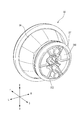
- FIG. 1st embodiment It is a perspective view which shows the headlamp which concerns on 1st embodiment. It is a front view which shows a part of headlamp of FIG. It is a perspective view which shows a part of headlamp of FIG. It is a perspective view which shows a part of headlamp of FIG. It is a perspective view which shows a part of headlamp of FIG. It is a perspective view which shows a part of headlamp of FIG. It is a perspective view which shows a part of headlamp of FIG. It is a perspective view which shows the heat radiating member in the headlamp of FIG. It is a perspective view which shows the heat radiating member in the headlamp of FIG. It is sectional drawing which shows a part of headlamp of FIG. It is a perspective view which shows a part of headlamp of FIG.
- an arrow F indicates the forward direction of the illustrated structure.
- Arrow B indicates the backward direction of the illustrated structure.
- Arrow U indicates the upward direction of the illustrated structure.
- Arrow D indicates the downward direction of the illustrated structure.
- Arrow R indicates the right direction of the illustrated structure.
- Arrow L indicates the left direction of the illustrated structure. “Right” and “left” used in the following description indicate the left and right directions viewed from the driver's seat.
- FIG. 1 shows an appearance of a headlamp 20 (an example of a lighting device) according to the first embodiment viewed from the upper left front.
- the headlamp 20 is mounted on the front of the vehicle.
- the headlamp 20 includes a housing 21 and a translucent cover 22.
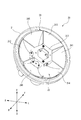
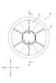
- FIG. 2 is a front view showing the appearance of the headlamp 20 with the translucent cover 22 removed from the state shown in FIG.
- the translucent cover 22 is attached to the housing 21 to partition the lamp chamber 23.
- the headlamp 20 includes a reflector member 24.
- the reflector member 24 is accommodated in the lamp chamber 23.
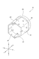
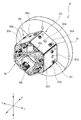
- FIG. 3 shows the appearance of the headlamp 20 in the state shown in FIG. 2 as viewed from the upper left front.
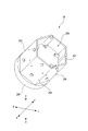
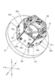
- FIG. 4 shows an appearance of the headlamp 20 in the same state as viewed from the lower right front.
- the reflector member 24 is an integrally molded product made of resin or the like.
- the reflector member 24 includes a left reflecting surface 241 (an example of a first reflecting surface), a right reflecting surface 242 (an example of a second reflecting surface), an upper left reflecting surface 243, a lower left reflecting surface 244, an upper right reflecting surface 245, a lower A right reflecting surface 246 and an opaque cover portion 247 are included.
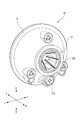
- FIG. 5 shows an external view of the headlamp 20 from which the reflector member 24 is removed from the state shown in FIG.
- FIG. 6 shows an appearance of the headlamp 20 from which the reflector member 24 is removed from the state shown in FIG.
- the headlamp 20 includes a left light source unit 251, a right light source unit 252, an upper left light source unit 253, a lower left light source unit 254, an upper right light source unit 255, and a lower right light source unit 256.
- the left light source unit 251 includes a left light source 251a (an example of a first light source), a left circuit board 251b, and a left connector 251c.
- the left circuit board 251b supports the left light source 251a and the left connector 251c.
- the left circuit board 251b includes a circuit that electrically connects the left light source 251a and the left connector 251c.
- the right light source unit 252 includes a right light source 252a (an example of a second light source), a right circuit board 252b, and a right connector 252c.
- the right circuit board 252b supports the right light source 252a and the right connector 252c.
- the right circuit board 252b includes a circuit that electrically connects the right light source 252a and the right connector 252c.
- the upper left light source unit 253 includes an upper left light source 253a, an upper left circuit board 253b, and an upper left connector 253c.
- the upper left circuit board 253b supports the upper left light source 253a and the upper left connector 253c.
- the upper left circuit board 253b includes a circuit that electrically connects the upper left light source 253a and the upper left connector 253c.
- the lower left light source unit 254 includes a lower left light source 254a, a lower left circuit board 254b, and a lower left connector 254c.
- the lower left circuit board 254b supports the lower left light source 254a and the lower left connector 254c.
- the lower left circuit board 254b includes a circuit that electrically connects the lower left light source 254a and the lower left connector 254c.
- the upper right light source unit 255 includes an upper right light source 255a, an upper right circuit board 255b, and an upper right connector 255c.
- the upper right circuit board 255b supports the upper right light source 255a and the upper right connector 255c.
- the upper right circuit board 255b includes a circuit that electrically connects the upper right light source 255a and the upper right connector 255c.
- the lower right light source unit 256 includes a lower right light source 256a, a lower right circuit board 256b, and a lower right connector 256c.
- the lower right circuit board 256b supports the lower right light source 256a and the lower right connector 256c.
- the lower right circuit board 256b includes a circuit that electrically connects the lower right light source 256a and the lower right connector 256c.
- Left light source 251a, right light source 252a, upper left light source 253a, lower left light source 254a, upper right light source 255a, and lower right light source 256a are semiconductor light emitting elements that emit light having a predetermined wavelength.
- Examples of the semiconductor light emitting device include a light emitting diode (LED), a laser diode (LD), and an organic EL device.
- the headlamp 20 includes a heat dissipation member 26.
- the heat dissipation member 26 is formed of a material having a relatively high thermal conductivity such as metal.
- FIG. 7 shows the appearance of the heat dissipation member 26 as viewed from the upper left front.
- FIG. 8 shows the appearance of the heat dissipation member 26 as viewed from the lower right front.
- the heat radiation member 26 includes a left support surface 261, a right support surface 262, an upper left support surface 263, a lower left support surface 264, an upper right support surface 265, and a lower right support surface 266.
- the left support surface 261 is a flat surface facing left.
- the upper left support surface 263 is a flat surface facing the upper left.
- the upper left support surface 263 is positioned to the right and above the left support surface 261.
- the lower left support surface 264 is a flat surface facing the lower left.
- the lower left support surface 264 is located to the right and below the left support surface 261.
- the right support surface 262 is a flat surface facing right.
- the upper right support surface 265 is a flat surface facing the upper right.
- the upper right support surface 265 is located to the left and above the right support surface 262.
- the lower right support surface 266 is a flat surface facing the lower right.
- the lower right support surface 266 is located to the left and below the right support surface 262.
- the heat dissipation member 26 includes a wall portion 267.
- the wall portion 267 defines a bottomed hollow portion 268.
- the hollow portion 268 opens forward.
- the left support surface 261, right support surface 262, upper left support surface 263, upper right support surface 265, lower left support surface 264, and lower right support surface 266 are part of the wall portion 267.
- the left support surface 261 supports the left circuit board 251b.
- the upper left support surface 263 supports the upper left circuit board 253b.
- the upper right support surface 265 supports the upper right circuit board 255b.
- the right support surface 262 supports the right circuit board 252b.
- the lower left support surface 264 supports the lower left circuit board 254b.
- the lower right support surface 266 supports the lower right circuit board 256b.
- the heat radiating member 26 is configured to dissipate heat generated by the operations of the left light source 251a, right light source 252a, upper left light source 253a, lower left light source 254a, upper right light source 255a, and lower right light source 256a.
- the left light source 251a, the right light source 252a, the upper left light source 253a, the lower left light source 254a, the upper right light source 255a, and the lower right light source 256a are arranged at positions facing the hollow portion 268 across the wall portion 267 of the heat radiating member 26. ing.
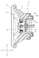
- FIG. 9 shows a configuration in which the cross section of the headlamp 20 taken along line V2-V2 in FIG. 2 is viewed from the arrow direction.
- a translucent cover 22 is also included in the figure.
- FIG. 10 shows the appearance of the headlamp 20 as viewed from the upper left rear.
- a rear end portion 269 of the heat radiating member 26 is exposed to the outside of the headlamp 20 through a first opening 211 formed in the rear portion of the housing 21.
- the headlamp 20 includes a first sealing member 271.
- the first sealing member 271 is made of an elastically deformable material.
- the first sealing member 271 seals the gap between the first opening 211 of the housing 21 and the rear end portion 269 of the heat dissipation member 26.
- Examples of the first sealing member 271 include an O-ring and a gasket.
- the headlamp 10 includes a second sealing member 272.
- the second sealing member 272 is made of an elastically deformable material.
- the second sealing member 272 is fitted into a second opening 212 formed in the rear part of the housing 21.
- the second opening 212 is sealed with a second sealing member 272.
- the headlamp 20 includes a plurality of conductive wires 28.
- the plurality of conductive wires 28 are led out of the headlamp 20 through a plurality of through holes formed in the second sealing member 272.
- the plurality of conductive wires 28 are electrically connected to a vehicle-side control unit (not shown).
- the plurality of conductors 28 include a left connector 251c of the left light source unit 251, a right connector 252c of the right light source unit 252, an upper left connector 253c of the upper left light source unit 253, and a lower left light source unit.
- the lower left connector 254c of the H.254, the upper right connector 255c of the upper right light source unit 255, and the lower right connector 256c of the lower right light source unit 256 are connected.
- the plurality of conductive wires 28 are a conductive wire electrically connected to the left light source 251a (an example of a first conductive wire), a conductive wire electrically connected to the right light source 252a (an example of a second conductive wire), and an upper left light source 253a.
- the reflector member 24 is attached to the heat radiating member 26.
- the opaque cover portion 247 of the reflector member 24 covers at least the front end of the left circuit board 251b, at least the front end of the upper left circuit board 253b, and at least the front end of the upper right circuit board 255b. Yes.
- the left reflecting surface 241, the upper left reflecting surface 243, and the upper right reflecting surface 245 of the reflector member 24 cover the left connector 251c, the upper left connector 253c, and the upper right connector 255c from at least the front. Further, the left reflecting surface 241, the upper left reflecting surface 243, and the upper right reflecting surface 245 of the reflector member 24 at least provide a plurality of conductive wires 28 connected to the left connector 251c, the upper left connector 253c, and the upper right connector 255c. Covering from the front.
- the opaque cover portion 247 of the reflector member 24 covers at least the front end of the right circuit board 252b, at least the front end of the lower left circuit board 254b, and at least the front end of the lower right circuit board 256b. Yes.
- the right reflecting surface 242, the lower left reflecting surface 244, and the lower right reflecting surface 246 of the reflector member 24 cover the right connector 252c, the lower left connector 254c, and the lower right connector 256c at least from the front. Further, the right reflecting surface 242, the lower left reflecting surface 244, and the lower right reflecting surface 246 of the reflector member 24 provide at least a plurality of conductive wires 28 connected to the right connector 252 c, the lower left connector 254 c, and the lower right connector 256 c. Covering from the front.
- Electrical energy (at least one of voltage and current, the value of which may change over time) supplied from the control unit on the vehicle side is transmitted to the left light source 251a, right light source 252a, upper left The light source 253a, the lower left light source 254a, the upper right light source 255a, and the lower right light source 256a are supplied.
- the left light source 251a when electric energy is supplied to the left light source 251a, the left light source 251a emits light to the left (an example of a direction intersecting the front-rear direction).
- the light emitted from the left light source 251 a is reflected forward (an example of a predetermined direction) by the left reflecting surface 241 of the reflector member 24.
- the reflected light passes through the translucent cover 22 and illuminates the front of the headlamp 20.
- the upper left light source 253a when electrical energy is supplied to the upper left light source 253a (an example of a third light source), the upper left light source 253a emits light to the upper left (an example of a direction that intersects with the front-rear direction).
- the light emitted from the upper left light source 253 a is reflected forward by the upper left reflecting surface 243 of the reflector member 24.
- the reflected light passes through the translucent cover 22 and illuminates the front of the headlamp 20.
- the upper right light source 255a when electrical energy is supplied to the upper right light source 255a (an example of a third light source), the upper right light source 255a emits light to the upper right (an example of a direction intersecting with the front-rear direction).
- the light emitted from the upper right light source 255 a is reflected forward by the upper right reflecting surface 245 of the reflector member 24.
- the reflected light passes through the translucent cover 22 and illuminates the front of the headlamp 20.
- the right light source 252a when electric energy is supplied to the right light source 252a, the right light source 252a emits light to the right (an example of a direction intersecting with the front-rear direction).
- the light emitted from the right light source 252a is reflected forward (an example of a predetermined direction) by the right reflecting surface 242 of the reflector member 24.
- the reflected light passes through the translucent cover 22 and illuminates the front of the headlamp 20.
- the lower left light source 254a when electrical energy is supplied to the lower left light source 254a (an example of a third light source), the lower left light source 254a emits light to the lower left (an example of a direction that intersects with the front-rear direction).
- the light emitted from the lower left light source 254 a is reflected forward by the lower left reflecting surface 244 of the reflector member 24.
- the reflected light passes through the translucent cover 22 and illuminates the front of the headlamp 20.
- the lower right light source 256a when electric energy is supplied to the lower right light source 256a (an example of a third light source), the lower right light source 256a emits light to the lower right (an example of a direction intersecting with the front-rear direction).
- the light emitted from the lower right light source 256 a is reflected forward and upward by the lower right reflecting surface 246 of the reflector member 24.
- the reflected light passes through the translucent cover 22 and illuminates the front of the headlamp 20.
- the headlamp 20 includes the reflector member 24, the left light source 251a, the right light source 252a, and the heat radiating member 26.
- the heat dissipating member 26 has a wall portion 267 that partitions the hollow portion 268.
- the heat dissipation member 26 dissipates heat generated by the operations of the left light source 251a and the right light source 252a.
- the reflector member 24 is attached to the heat dissipation member 26.
- the left light source 251a and the right light source 252a are respectively disposed at positions facing the hollow portion 268 with the wall portion 267 interposed therebetween.
- the left light source 251a and the right light source 252a emit light in a direction intersecting with the front-rear direction of the headlamp 20, respectively.
- the reflector member 24 is an integrally molded product and includes a left reflecting surface 241 and a right reflecting surface 242.
- the left reflecting surface 241 reflects light emitted from the left light source 251a in a predetermined direction.
- the right reflecting surface 242 reflects light emitted from the right light source 252a in a predetermined direction.
- the light emitted from the left light source 251a is reflected by the left reflecting surface 241 of the reflector member 24, and the light emitted from the right light source 252a is reflected by the right reflecting surface 242 of the reflector member 24. Since the space that extends in the direction crossing the front-rear direction of the headlamp 20 having a relatively high degree of freedom in layout can be used efficiently, the light distribution control of the light emitted forward from the light source by the lens portion formed on the translucent cover Compared to a configuration such as Patent Document 1, the enlargement in the front-rear direction is easily suppressed.
- the left light source 251a and the right light source 252a are arranged at positions facing the hollow portion 268 of the heat radiating member 26 having a large surface area, heat generated by the operations of the left light source 251a and the right light source 252a can be efficiently dissipated. Therefore, the volume of the heat dissipating member 26 necessary for obtaining the desired heat dissipating performance can be reduced, and the enlargement of the headlamp 20 can be suppressed.
- the left reflecting surface 241 and the right reflecting surface 242 are part of a single reflector member 24, the number of steps for mounting on the heat radiating member 26 can be minimized.
- the headlamp 20 includes a plurality of conductive wires 28 electrically connected to the left light source 251a and the right light source 252a.
- the plurality of conductive wires 28 are disposed behind the reflector member 24.
- the reflector member 24 attached to the heat radiating member 26 can have a function of covering the plurality of conductive wires 28. Thereby, the number of parts is reduced and the enlargement of the headlamp 20 can be suppressed.
- the left light source 251a, the right light source 252a, the upper left light source 253a, the lower left light source 254a, the upper right light source 255a, and the lower right light source 256a emit light in a direction intersecting with the front-rear direction of the headlamp 20. Exit.
- three or more light sources can be arranged with high space utilization efficiency. Therefore, the enlargement of the headlamp 20 can be suppressed.
- the single reflector member 24 attached to the heat dissipation member 26 includes the upper left reflecting surface 241, the right reflecting surface 242, the upper left reflecting surface 243, the lower left reflecting surface 244, and the upper right reflecting surface 245. , And a lower right reflecting surface 246.
- the reflector member 24 is formed by integrating a plurality of subunits, and each subunit is formed from a plurality of light sources arranged at positions facing the hollow portion 268 across the wall portion 267 of the heat radiating member 26. A configuration having a plurality of reflecting surfaces that reflect the emitted light may be employed.
- the plurality of conductive wires 28 are connected to the left light source 251a, the left connector 251c, the right connector 252c, the upper left connector 253c, the lower left connector 254c, the upper right connector 255c, and the lower right connector 256c, respectively.
- the right light source 252a, the upper left light source 253a, the lower left light source 254a, the upper right light source 255a, and the lower right light source 256a are electrically connected.
- the plurality of conductive wires 28 can be electrically connected to each light source without using a connector, for example, by soldering to a contact.
- the left reflecting surface of the reflector member 24 so that the left light source 251a, the right light source 252a, the upper left light source 253a, the lower left light source 254a, the upper right light source 255a, and the lower right light source 256a all illuminate the front.
- 241, a right reflecting surface 242, an upper left reflecting surface 243, a lower left reflecting surface 244, an upper right reflecting surface 245, and a lower right reflecting surface 246 are configured.
- the area illuminated by each light source can be appropriately determined according to the specifications of the headlamp.
- the left reflecting surface 241 and the right reflecting surface 242 of the reflector member 24 can be configured such that the left light source 251a and the right light source 252a illuminate different areas in front of the headlamp 20.
- the headlamp 20 is illustrated as an example of a lighting device.
- the present invention can be applied to various lighting devices that are configured to be mounted on a vehicle and include a plurality of light sources and heat dissipation members.
- the front-rear direction, the left-right direction, and the up-down direction of the headlamp 20 coincide with the front-rear direction, the left-right direction, and the up-down direction of the vehicle.
- at least one of the front-rear direction, the left-right direction, and the up-down direction of the lighting device does not coincide with the front-back direction, the left-right direction, and the up-down direction of the vehicle.
- FIG. 11 shows an appearance of the headlamp 30 (an example of a lighting device) according to the second embodiment as viewed from the upper left front.
- the headlamp 30 is mounted on the front of the vehicle.
- the headlamp 30 includes a translucent cover 32 and a reflector member 34.
- FIG. 12 is a front view showing the appearance of the headlamp 30 with the translucent cover 32 removed from the state shown in FIG.
- the translucent cover 32 is attached to the reflector member 34 to partition the lamp chamber 33.
- FIG. 13 shows the appearance of the headlamp 30 in the state shown in FIG. 12 as viewed from the upper left front.
- FIG. 14 shows the appearance of the headlamp 30 in the same state as viewed from the lower right front.
- the reflector member 34 is an integrally molded product made of resin or the like.
- the reflector member 34 includes a left reflecting surface 341 (an example of a first reflecting surface), a right reflecting surface 342 (an example of a second reflecting surface), an upper left reflecting surface 343, a lower left reflecting surface 344, an upper right reflecting surface 345, a lower A right reflecting surface 346 and an opaque cover portion 347 are included.
- FIG. 15 shows an external view of the headlamp 30 from which the reflector member 34 is removed from the state shown in FIG.
- FIG. 16 shows an external appearance of the headlamp 30 from which the reflector member 34 is removed from the state shown in FIG.
- the headlamp 30 includes a left light source unit 351, a right light source unit 352, an upper left light source unit 353, a lower left light source unit 354, an upper right light source unit 355, and a lower right light source unit 356.
- the left light source unit 351 includes a left light source 351a (an example of a first light source), a left circuit board 351b, and a left connector 351c.
- the left circuit board 351b supports the left light source 351a and the left connector 351c.
- the left circuit board 351b includes a circuit that electrically connects the left light source 351a and the left connector 351c.
- the right light source unit 352 includes a right light source 352a (an example of a second light source), a right circuit board 352b, and a right connector 352c.
- the right circuit board 352b supports the right light source 352a and the right connector 352c.
- the right circuit board 352b includes a circuit that electrically connects the right light source 352a and the right connector 352c.
- the upper left light source unit 353 includes an upper left light source 353a, an upper left circuit board 353b, and an upper left connector 353c.
- the upper left circuit board 353b supports the upper left light source 353a and the upper left connector 353c.
- the upper left circuit board 353b includes a circuit that electrically connects the upper left light source 353a and the upper left connector 353c.
- the lower left light source unit 354 includes a lower left light source 354a, a lower left circuit board 354b, and a lower left connector 354c.
- the lower left circuit board 354b supports the lower left light source 354a and the lower left connector 354c.
- the lower left circuit board 354b includes a circuit that electrically connects the lower left light source 354a and the lower left connector 354c.
- the upper right light source unit 355 includes an upper right light source 355a, an upper right circuit board 355b, and an upper right connector 355c.
- the upper right circuit board 355b supports the upper right light source 355a and the upper right connector 355c.
- the upper right circuit board 355b includes a circuit that electrically connects the upper right light source 355a and the upper right connector 355c.
- the lower right light source unit 356 includes a lower right light source 356a, a lower right circuit board 356b, and a lower right connector 356c.
- the lower right circuit board 356b supports the lower right light source 356a and the lower right connector 356c.
- the lower right circuit board 356b includes a circuit that electrically connects the lower right light source 356a and the lower right connector 356c.
- Left light source 351a, right light source 352a, upper left light source 353a, lower left light source 354a, upper right light source 355a, and lower right light source 356a are semiconductor light emitting elements that emit light including a predetermined wavelength.
- Examples of the semiconductor light emitting device include a light emitting diode (LED), a laser diode (LD), and an organic EL device.
- the headlamp 30 includes a heat radiating member 36.
- the heat radiating member 36 is formed of a material having a relatively high thermal conductivity such as a metal.
- FIG. 17 shows the external appearance of the heat dissipation member 36 as viewed from the upper left front.
- FIG. 18 shows an appearance of the heat radiating member 36 as viewed from the lower right front.
- the heat dissipation member 36 includes a left support surface 361, a right support surface 362, an upper left support surface 363, a lower left support surface 364, an upper right support surface 365, and a lower right support surface 366.
- the left support surface 361 is a flat surface facing left.
- the upper left support surface 363 is a flat surface facing the upper left.
- the upper left support surface 363 is located to the right and above the left support surface 361.
- the lower left support surface 364 is a flat surface facing the lower left.
- the lower left support surface 364 is located to the right and below the left support surface 361.
- the right support surface 362 is a flat surface facing right.
- the upper right support surface 365 is a flat surface facing upward to the right.
- the upper right support surface 365 is located to the left and above the right support surface 362.
- the lower right support surface 366 is a flat surface facing the lower right.
- the lower right support surface 366 is located to the left and below the right support surface 362.
- the heat radiation member 36 includes a wall portion 367.
- the wall portion 367 defines a hollow portion 368 that is a through hole that opens in the front-rear direction.
- the left support surface 361, the right support surface 362, the upper left support surface 363, the upper right support surface 365, the lower left support surface 364, and the lower right support surface 366 are part of the wall portion 367.
- the left support surface 361 supports the left circuit board 351b.
- the upper left support surface 363 supports the upper left circuit board 353b.
- the upper right support surface 365 supports the upper right circuit board 355b.
- the right support surface 362 supports the right circuit board 352b.
- the lower left support surface 364 supports the lower left circuit board 354b.
- the lower right support surface 366 supports the lower right circuit board 356b.
- the heat radiation member 36 is configured to dissipate heat generated by the operations of the left light source 351a, right light source 352a, upper left light source 353a, lower left light source 354a, upper right light source 355a, and lower right light source 356a.
- the left light source 351a, the right light source 352a, the upper left light source 353a, the lower left light source 354a, the upper right light source 355a, and the lower right light source 356a are disposed at positions facing the hollow portion 368 across the wall portion 367 of the heat dissipation member 36. ing.
- a part of the wall portion 367 forming the left support surface 361 has a left concave portion 361a.
- the left recess 361a is open forward.
- the left connector 351c is received in the left recess 361a.
- the left connector 351c is disposed in the hollow portion 368.
- a part of the wall portion 367 forming the right support surface 362 has a right concave portion 362a.
- the right recess 362a is open forward.
- the right connector 352c is received in the right recess 362a.
- the right connector 352c is disposed in the hollow portion 368.
- a part of the wall portion 367 forming the upper left support surface 363 has an upper left recess 363a.
- the upper left recess 363a opens forward.
- the upper left connector 353c is received in the upper left recess 363a.
- the upper left connector 353c is disposed in the hollow portion 368.
- a part of the wall portion 367 forming the lower left support surface 364 has a lower left recess 364a.
- the lower left recess 364a is open forward.
- the lower left connector 354c is received in the lower left recess 364a.
- the lower left connector 354 c is disposed in the hollow portion 368.
- a part of the wall portion 367 forming the upper right support surface 365 has an upper right concave portion 365a.
- the upper right recess 365a is open forward.
- the upper right connector 355c is received in the upper right recess 365a.
- the upper right connector 355c is disposed in the hollow portion 368.
- a part of the wall portion 367 forming the lower right support surface 366 has a lower right concave portion 366a.
- the lower right recess 366a is open forward.
- the lower right connector 356c is received in the lower right recess 366a.
- the lower right connector 356c is disposed in the hollow portion 368.
- FIG. 19 shows a configuration in which the cross section of the headlamp 30 taken along line V3-V3 in FIG. 12 is viewed from the arrow direction.
- a translucent cover 32 is also included in the figure.
- FIG. 20 shows an appearance of the headlamp 30 as viewed from the upper left rear.
- heat radiating member 36 Most of the heat radiating member 36 is accommodated in the lamp chamber 33. A rear end portion 369 of the heat radiating member 36 is exposed to the outside of the headlamp 30 through an opening 348 formed in the rear portion of the reflector member 34.
- the headlamp 30 includes a first sealing member 371.
- the first sealing member 371 is made of an elastically deformable material.
- the first sealing member 371 seals the gap between the opening 348 of the reflector member 34 and the rear end portion 369 of the heat dissipation member 36.
- Examples of the first sealing member 371 include an O-ring and a gasket.
- the headlamp 10 includes a second sealing member 372.
- the second sealing member 372 is made of an elastically deformable material.
- the second sealing member 372 is fitted into the rear portion of the hollow portion 368 of the heat radiating member 36.
- the rear part of the hollow part 368 is sealed with a second sealing member 372.
- the headlamp 30 includes a plurality of conductive wires 38.
- the plurality of conductive wires 38 are led out of the headlamp 30 through a plurality of through holes formed in the second sealing member 372.
- the plurality of conductive wires 38 are electrically connected to a vehicle-side control unit (not shown).
- the plurality of conductive wires 38 extend through the hollow portion 368 of the heat radiating member 36, and the left connector 351 c of the left light source unit 351, the right connector 352 c of the right light source unit 352, and the upper left light source unit.
- the upper left connector 353c, the lower left connector 354c of the lower left light source unit 354, the upper right connector 355c of the upper right light source unit 355, and the lower right connector 356c of the lower right light source unit 356 are connected from the front.
- the plurality of conducting wires 38 are a conducting wire electrically connected to the left light source 351a (an example of a first conducting wire), a conducting wire electrically connected to the right light source 352a (an example of a second conducting wire), and an upper left light source 353a.
- the reflector member 34 is attached to the heat radiating member 36.
- the left connector 351 c, the upper left connector 353 c, and the upper right connector 355 c are respectively formed on the left reflecting surface 341, the upper left reflecting surface 343, and the upper right reflecting surface 345 of the reflector member 34. It is arranged in the front.
- the opaque cover portion 347 of the reflector member 34 covers at least the front end of the left circuit board 351b, at least the front end of the upper left circuit board 353b, and at least the front end of the upper right circuit board 355b.
- the opaque cover portion 347 covers the left connector 351c, the upper left connector 353c, the upper right connector 355c, and the plurality of conductive wires 38 connected thereto at least from the front.
- the right connector 352c, the lower left connector 354c, and the lower right connector 356c are respectively formed on the right reflecting surface 342, the lower left reflecting surface 344, and the lower right reflecting surface 346 of the reflector member 34. It is arranged in the front.
- the opaque cover portion 347 of the reflector member 34 covers at least the front end of the right circuit board 352b, at least the front end of the lower left circuit board 354b, and at least the front end of the lower right circuit board 356b.
- the opaque cover portion 347 covers the right connector 352c, the lower left connector 354c, the lower right connector 356c, and the plurality of conductive wires 38 connected thereto from at least the front.
- Electrical energy (at least one of voltage and current, the value of which may change over time) supplied from the control unit on the vehicle side is transmitted to the left light source 351a, the right light source 352a, and the upper left
- the light source 353a, the lower left light source 354a, the upper right light source 355a, and the lower right light source 356a are supplied to each.
- the left light source 351a when electric energy is supplied to the left light source 351a, the left light source 351a emits light to the left (an example of a direction intersecting with the front-rear direction).
- the light emitted from the left light source 351a is reflected forward (an example of a predetermined direction) by the left reflecting surface 341 of the reflector member 34.
- the reflected light passes through the translucent cover 32 and illuminates the front of the headlamp 30.
- the upper left light source 353a when electrical energy is supplied to the upper left light source 353a (an example of a third light source), the upper left light source 353a emits light to the upper left (an example of a direction intersecting with the front-rear direction).
- the light emitted from the upper left light source 353 a is reflected forward by the upper left reflecting surface 343 of the reflector member 34.
- the reflected light passes through the translucent cover 32 and illuminates the front of the headlamp 30.
- the upper right light source 355a when electrical energy is supplied to the upper right light source 355a (an example of a third light source), the upper right light source 355a emits light to the upper right (an example of a direction intersecting with the front-rear direction).
- the light emitted from the upper right light source 355a is reflected forward by the upper right reflecting surface 345 of the reflector member 34.
- the reflected light passes through the translucent cover 32 and illuminates the front of the headlamp 30.
- the right light source 352a when electric energy is supplied to the right light source 352a, the right light source 352a emits light to the right (an example of a direction intersecting with the front-rear direction).
- the light emitted from the right light source 352a is reflected forward (an example of a predetermined direction) by the right reflecting surface 342 of the reflector member 34.
- the reflected light passes through the translucent cover 32 and illuminates the front of the headlamp 30.
- the lower left light source 354a when electrical energy is supplied to the lower left light source 354a (an example of a third light source), the lower left light source 354a emits light to the lower left (an example of a direction intersecting the front-rear direction).
- the light emitted from the lower left light source 354 a is reflected forward by the lower left reflecting surface 344 of the reflector member 34.
- the reflected light passes through the translucent cover 32 and illuminates the front of the headlamp 30.
- the lower right light source 356a when electrical energy is supplied to the lower right light source 356a (an example of a third light source), the lower right light source 356a emits light to the lower right (an example of a direction intersecting the front-rear direction).
- the light emitted from the lower right light source 356a is reflected forward and upward by the lower right reflecting surface 346 of the reflector member 34.
- the reflected light passes through the translucent cover 32 and illuminates the front of the headlamp 30.
- the headlamp 30 can include an adjustment mechanism 39 shown in FIG.
- the adjustment mechanism 39 includes a screw 391, a joint 392, a support plate 393, and an attitude control plate 394.
- the screw 391 includes a screw head 391a and a screw shaft 391b.
- the screw 391 extends through the lower part of the support plate 393.
- the screw head 391a can be rotated by a predetermined tool.
- a screw groove is formed on the outer peripheral surface of the screw shaft 391b.
- the joint 392 is provided below the attitude control plate 394.
- the joint 392 has a through hole.
- a screw groove (not shown) is formed on the inner peripheral surface of the through hole.
- the screw shaft 391b extends in the through hole of the joint 392.
- the thread groove formed on the outer peripheral surface of the screw shaft 391b is screwed with the thread groove formed in the through hole of the joint 392.
- the support plate 393 is fixed at a predetermined position in the vehicle.
- the attitude control plate 394 is fixed to the rear part of the reflector member 34.
- the upper part of the attitude control plate 394 is connected to the support plate 393 via a pair of connecting portions 394a.
- the pair of connecting portions 394a is configured by a universal joint or the like, and can be displaced at least in the vertical direction.
- the screw shaft 391b rotates in the operation direction.
- the rotation of the screw shaft 391b is converted into the movement of the joint 392 in the front-rear direction via the thread groove.
- the reflector member 34 can be tilted forward or backward from the original posture, and an error from a predetermined specification can be eliminated.
- Such adjustment of the attitude of the reflector member 34 is performed before shipping the headlamp 30 or during maintenance inspection.
- the headlamp 30 includes the reflector member 34, the left light source 351a, the right light source 352a, and the heat radiating member 36.
- the heat radiating member 36 has a wall portion 367 that defines the hollow portion 368.
- the heat radiating member 36 dissipates heat generated by the operations of the left light source 351a and the right light source 352a.
- the reflector member 34 is attached to the heat radiating member 36.
- the left light source 351a and the right light source 352a are respectively disposed at positions facing the hollow portion 368 across the wall portion 367.
- the left light source 351a and the right light source 352a emit light in a direction intersecting with the front-rear direction of the headlamp 30, respectively.
- the reflector member 34 is an integrally molded product and includes a left reflecting surface 341 and a right reflecting surface 342.
- the left reflecting surface 341 reflects the light emitted from the left light source 351a in a predetermined direction.
- the right reflecting surface 342 reflects the light emitted from the right light source 352a in a predetermined direction.
- the light emitted from the left light source 351a is reflected by the left reflecting surface 341 of the reflector member 34, and the light emitted from the right light source 352a is reflected by the right reflecting surface 342 of the reflector member 34. Since the space that extends in the direction crossing the front-rear direction of the headlamp 30 with a relatively high degree of layout freedom can be used efficiently, the light distribution control of the light emitted forward from the light source by the lens part formed on the translucent cover Compared to a configuration such as Patent Document 1, the enlargement in the front-rear direction is easily suppressed.
- the left light source 351a and the right light source 352a are arranged at positions facing the hollow portion 368 of the heat radiating member 36 having a large surface area, heat generated by the operations of the left light source 351a and the right light source 352a can be efficiently dissipated. Therefore, the volume of the heat radiating member 36 necessary for obtaining the desired heat radiating performance can be reduced, and the enlargement of the headlamp 30 can be suppressed.
- the left reflecting surface 341 and the right reflecting surface 342 are part of a single reflector member 34, the number of steps for mounting on the heat radiating member 36 can be minimized.
- the headlamp 30 includes a plurality of conductive wires 38 electrically connected to the left light source 351a and the right light source 352a.
- the plurality of conductive wires 38 extend in the hollow portion 368 of the heat dissipation member 36.
- the hollow portion 368 formed in order to improve heat dissipation is used as a routing space for the plurality of conductive wires 38. Thereby, the utilization efficiency of space improves and the enlargement of the headlamp 30 can be suppressed.
- the translucent cover 32 is attached to the reflector member 34.
- the reflector member 34 can function as a housing that partitions the lamp chamber 33.
- a mechanism for adjusting the posture of the reflector member 34 may be provided outside the reflector member 34 as necessary. Therefore, the enlargement of the headlamp 30 can be further suppressed.
- a watertight structure can be formed by the translucent cover 32, the reflector member 34, the first sealing member 371, and the second sealing member 372.
- the left light source 351a, the right light source 352a, the upper left light source 353a, the lower left light source 354a, the upper right light source 355a, and the lower right light source 356a emit light in a direction that intersects the front-rear direction of the headlamp 30. Exit.
- three or more light sources can be arranged with high space utilization efficiency. Therefore, the enlargement of the headlamp 30 can be suppressed.
- the single reflector member 34 attached to the heat radiating member 36 includes the upper left reflecting surface 341, the right reflecting surface 342, the upper left reflecting surface 343, the lower left reflecting surface 344, and the upper right reflecting surface 345. , And a lower right reflecting surface 346.
- the reflector member 34 is formed by integrating a plurality of subunits, and each subunit is formed from a plurality of light sources arranged at positions facing the hollow portion 368 across the wall portion 367 of the heat radiating member 36. A configuration having a plurality of reflecting surfaces that reflect the emitted light may be employed.
- the plurality of conductors 38 are connected to the left light source 351a, the left connector 351c, the right connector 352c, the upper left connector 353c, the lower left connector 354c, the upper right connector 355c, and the lower right connector 356c, respectively.
- the right light source 352a, the upper left light source 353a, the lower left light source 354a, the upper right light source 355a, and the lower right light source 356a are electrically connected.
- the plurality of conductive wires 38 can be electrically connected to each light source without passing through a connector, for example, by soldering to a contact.
- the left reflecting surface of the reflector member 34 so that the left light source 351a, the right light source 352a, the upper left light source 353a, the lower left light source 354a, the upper right light source 355a, and the lower right light source 356a all illuminate the front.
- a right reflecting surface 342, an upper left reflecting surface 343, a lower left reflecting surface 344, an upper right reflecting surface 345, and a lower right reflecting surface 346 are configured.
- the area illuminated by each light source can be appropriately determined according to the specifications of the headlamp.
- the left reflecting surface 341 and the right reflecting surface 342 of the reflector member 34 can be configured such that the left light source 351a and the right light source 352a illuminate different areas in front of the headlamp 30.
- the headlamp 30 is illustrated as an example of a lighting device.
- the present invention can be applied to various lighting devices that are configured to be mounted on a vehicle and include a plurality of light sources and heat dissipation members.
- the front-rear direction, left-right direction, and up-down direction of the headlamp 30 are the same as the front-rear direction, left-right direction, and up-down direction of the vehicle.
- at least one of the front-rear direction, the left-right direction, and the up-down direction of the lighting device does not coincide with the front-back direction, the left-right direction, and the up-down direction of the vehicle.
Landscapes
- Engineering & Computer Science (AREA)
- General Engineering & Computer Science (AREA)
- Physics & Mathematics (AREA)
- Optics & Photonics (AREA)
- Microelectronics & Electronic Packaging (AREA)
- Non-Portable Lighting Devices Or Systems Thereof (AREA)
- Arrangement Of Elements, Cooling, Sealing, Or The Like Of Lighting Devices (AREA)
- Lighting Device Outwards From Vehicle And Optical Signal (AREA)
Abstract
放熱部材(26)は、左光源(251a)と上左光源(253a)の動作により生じる熱を放散する。放熱部材(26)は、中空部(268)を区画する壁部(267)を有している。左光源(251a)と上左光源(253a)は、壁部(267)を挟んで中空部(268)と対向する位置に配置されている。左光源(251a)と上左光源(253a)は、それぞれ前後方向と交差する方向に光を出射する。放熱部材(26)に装着される単一のリフレクタ部材は、左光源(251a)から出射された光を所定の方向に反射する反射面と、上左光源(253a)から出射された光を所定の方向に反射する反射面とを含んでいる。
Description
本発明は、車両に搭載される照明装置に関する。
特許文献1は、この種の照明装置の一例である二輪車用前照灯を開示している。当該前照灯は、複数の光源と放熱部材を備えている。放熱部材は、各光源から生じる熱を放散する。複数の光源と放熱部材は、ハウジングと透光カバーによって区画される灯室内に収容されている。透光カバーは、レンズ機能を有する部分を有している。各光源から出射された光は、当該レンズ機能を有する部分を通過することにより所定の向きに進行し、当該前照灯の前方を所定の配光パターンで照明する。
複数の光源と放熱部材を備える照明装置の大型化を抑制することが求められている。
上記の要求に応えるための第一態様は、車両に搭載される照明装置であって、
第一光源と、
第二光源と、
中空部を区画する壁を有し、前記第一光源と前記第二光源の動作により生じる熱を放散する放熱部材と、
前記放熱部材に装着されている単一のリフレクタ部材と、
を備えており、
前記第一光源と前記第二光源は、それぞれ前記壁を挟んで前記中空部と対向する位置に配置されており、
前記第一光源と前記第二光源は、それぞれ前後方向と交差する方向に光を出射し、
前記リフレクタ部材は、
前記第一光源から出射された光を所定の方向に反射する第一反射面と、
前記第二光源から出射された光を所定の方向に反射する第二反射面と、
を含んでいる。
第一光源と、
第二光源と、
中空部を区画する壁を有し、前記第一光源と前記第二光源の動作により生じる熱を放散する放熱部材と、
前記放熱部材に装着されている単一のリフレクタ部材と、
を備えており、
前記第一光源と前記第二光源は、それぞれ前記壁を挟んで前記中空部と対向する位置に配置されており、
前記第一光源と前記第二光源は、それぞれ前後方向と交差する方向に光を出射し、
前記リフレクタ部材は、
前記第一光源から出射された光を所定の方向に反射する第一反射面と、
前記第二光源から出射された光を所定の方向に反射する第二反射面と、
を含んでいる。
上記のような構成によれば、第一光源から出射された光をリフレクタ部材の第一反射面で反射し、第二光源から出射された光をリフレクタ部材の第二反射面で反射する。比較的レイアウト自由度の高い照明装置の前後方向と交差する向きに広がる空間を効率よく利用できるため、光源から前方に出射された光を透光カバーに形成されたレンズ部によって配光制御する特許文献1のような構成と比較すると、照明装置の前後方向の大型化を抑制しやすい。
また、第一光源と第二光源が表面積の大きい放熱部材の中空部と対向する位置に配置されているため、第一光源と第二光源の動作により生じる熱を効率的に放散できる。したがって、所望の放熱性能を得るために必要な放熱部材の体積を小さくでき、照明装置の大型化を抑制できる。
さらに、第一反射面と第二反射面は、単一のリフレクタ部材の一部であるため、放熱部材への装着に係る工数を最小限にできる。
上記の照明装置は、以下のように構成されうる。
前記第一光源と電気的に接続されている第一導線と、
前記第二光源と電気的に接続されている第二導線と、
を備えており、
前記第一導線と前記第二導線は、前記リフレクタ部材の後方に配置されている。
前記第一光源と電気的に接続されている第一導線と、
前記第二光源と電気的に接続されている第二導線と、
を備えており、
前記第一導線と前記第二導線は、前記リフレクタ部材の後方に配置されている。
このような構成によれば、放熱部材に装着されるリフレクタ部材に第一導線と第二導線を覆い隠す機能を担わせることができる。これにより、部品点数が削減され、複数の光源と放熱部材を備える照明装置の大型化を抑制できる。
あるいは、上記の照明装置は、以下のように構成されうる。
前記第一光源と電気的に接続されている第一導線と、
前記第二光源と電気的に接続されている第二導線と、
を備えており、
前記第一導線と前記第二導線は、前記中空部内を延びている。
前記第一光源と電気的に接続されている第一導線と、
前記第二光源と電気的に接続されている第二導線と、
を備えており、
前記第一導線と前記第二導線は、前記中空部内を延びている。
すなわち、放熱性を向上させるために形成された中空部が、第一導線と第二導線の配策スペースとして利用される。これにより、空間の利用効率が向上し、複数の光源と放熱部材を備える照明装置の大型化を抑制できる。
この場合、上記の照明装置は、以下のように構成されうる。
前記第一光源と前記第二光源から出射された光を通過させる透光カバーを備えており、
前記透光カバーは、前記リフレクタ部材に装着されている。
前記第一光源と前記第二光源から出射された光を通過させる透光カバーを備えており、
前記透光カバーは、前記リフレクタ部材に装着されている。
このような構成によれば、灯室を区画するハウジングとしての機能をリフレクタ部材に担わせることができる。リフレクタ部材の姿勢を調節する機構は、必要に応じてリフレクタ部材の外側に設ければよい。したがって、複数の光源と放熱部材を備える照明装置の大型化をさらに抑制できる。
上記の照明装置は、以下のように構成されうる。
前記壁を挟んで前記中空部と対向する位置に配置されている第三光源を備えており、
前記第三光源は、前記前後方向と交差する向きに光を出射する。
前記壁を挟んで前記中空部と対向する位置に配置されている第三光源を備えており、
前記第三光源は、前記前後方向と交差する向きに光を出射する。
このような構成によれば、三つ以上の光源を高い空間利用効率で配置できる。よって、複数の光源と放熱部材を備える照明装置の大型化を抑制できる。
上記の照明装置は、以下のように構成されうる。
前記第一光源は、第一領域を照明するための光を出射し、
前記第二光源は、前記第一領域と異なる第二領域を照明するための光を出射する。
前記第一光源は、第一領域を照明するための光を出射し、
前記第二光源は、前記第一領域と異なる第二領域を照明するための光を出射する。
このような構成によれば、異なる領域を照明するための複数の光源を高い空間利用効率で配置でき、複数の光源と放熱部材を備える照明装置の大型化を抑制可能である。
上記の要求に応えるための第二態様は、車両に搭載される照明装置であって、
第一光源と、
前記第一光源から出射された光を所定の方向へ反射する第一反射面と、
前記第一反射面の前方で前記第一光源と電気的に接続されている第一導線と、
第二光源と、
前記第二光源から出射された光を所定の方向へ反射する第二反射面と、
前記第二反射面の前方で前記第二光源と電気的に接続されている第二導線と、
前記第一導線と前記第二導線を少なくとも前方から覆っている不透明カバーと、
を備えている。
第一光源と、
前記第一光源から出射された光を所定の方向へ反射する第一反射面と、
前記第一反射面の前方で前記第一光源と電気的に接続されている第一導線と、
第二光源と、
前記第二光源から出射された光を所定の方向へ反射する第二反射面と、
前記第二反射面の前方で前記第二光源と電気的に接続されている第二導線と、
前記第一導線と前記第二導線を少なくとも前方から覆っている不透明カバーと、
を備えている。
反射光の進行を阻害しないように留意すれば、第一反射面と第二反射面の前方には比較的高い空間的余裕が存在する。このような空間を積極的に利用して光源との電気的接続を行なうことにより、反射面の後方において光源との電気的接続が行なわれている構成と比較すると、複数の光源を備える照明装置の大型化を特に前後方向について抑制できる。
他方、第一導線と第二導線は、不透明カバーによって少なくとも前方から覆われている。したがって、第一反射面と第二反射面の前方に光源との電気的接続部を配置しても、これが前方から視認されることを回避できる。したがって、商品価値の低下を回避しつつ、複数の光源を備える照明装置の大型化を抑制できる。
上記の照明装置は、以下のように構成されうる。
前記第一光源と電気的に接続された第一コネクタと、
前記第二光源と電気的に接続された第二コネクタと、
を備えており、
前記第一導線は、前方から前記第一コネクタに接続されており、
前記第二導線は、前方から前記第二コネクタに接続されており、
前記不透明カバーは、前記第一コネクタと前記第二コネクタを少なくとも前方から覆っている。
前記第一光源と電気的に接続された第一コネクタと、
前記第二光源と電気的に接続された第二コネクタと、
を備えており、
前記第一導線は、前方から前記第一コネクタに接続されており、
前記第二導線は、前方から前記第二コネクタに接続されており、
前記不透明カバーは、前記第一コネクタと前記第二コネクタを少なくとも前方から覆っている。
このような構成によれば、照明装置を組み立てる際に行なわれる第一導線と第二導線の接続作業を効率化できる。他方、第一コネクタと第二コネクタは、不透明カバーによって少なくとも前方から覆われている。したがって、第一反射面と第二反射面の前方に第一コネクタと第二コネクタを配置しても、これらが前方から視認されることを回避できる。したがって、商品価値の低下を回避しつつ、複数の光源を備える照明装置の組立て作業性を向上できる。
上記の照明装置は、以下のように構成されうる。
前記第一反射面、前記第二反射面、および前記不透明カバーは、単一のリフレクタ部材の一部である。
前記第一反射面、前記第二反射面、および前記不透明カバーは、単一のリフレクタ部材の一部である。
このような構成によれば、光源との電気的接続部を覆い隠す機能をリフレクタ部材に担わせることができる。これにより、部品点数が削減され、複数の光源を備える照明装置の大型化を抑制できる。
添付の図面を参照しつつ、実施形態の例について以下詳細に説明する。以下の説明に用いる各図面では、各部材を認識可能な大きさとするために縮尺を適宜変更している。
添付の図面において、矢印Fは、図示された構造の前方向を示している。矢印Bは、図示された構造の後方向を示している。矢印Uは、図示された構造の上方向を示している。矢印Dは、図示された構造の下方向を示している。矢印Rは、図示された構造の右方向を示している。矢印Lは、図示された構造の左方向を示している。以降の説明に用いる「右」および「左」は、運転席から見た左右の方向を示している。
図1は、第一実施形態に係る前照灯20(照明装置の一例)を左前上方から見た外観を示している。前照灯20は、車両の前部に搭載される。前照灯20は、ハウジング21と透光カバー22を備えている。
図2は、図1に示した状態から透光カバー22を取り外した前照灯20の外観を示す正面図である。透光カバー22は、ハウジング21に装着されて灯室23を区画している。前照灯20は、リフレクタ部材24を備えている。リフレクタ部材24は、灯室23内に収容されている。
図3は、図2に示された状態の前照灯20を左前上方から見た外観を示している。図4は、同状態の前照灯20を右前下方から見た外観を示している。
リフレクタ部材24は、樹脂などからなる一体成型品である。リフレクタ部材24は、左反射面241(第一反射面の一例)、右反射面242(第二反射面の一例)、上左反射面243、下左反射面244、上右反射面245、下右反射面246、不透明カバー部247を含んでいる。
図5は、図3に示された状態からリフレクタ部材24を取り外した前照灯20を左前上方から見た外観を示している。図6は、図4に示された状態からリフレクタ部材24を取り外した前照灯20を右前下方から見た外観を示している。
前照灯20は、左光源ユニット251、右光源ユニット252、上左光源ユニット253、下左光源ユニット254、上右光源ユニット255、および下右光源ユニット256を備えている。
左光源ユニット251は、左光源251a(第一光源の一例)、左回路基板251b、左コネクタ251cを備えている。左回路基板251bは、左光源251aと左コネクタ251cを支持している。左回路基板251bは、左光源251aと左コネクタ251cを電気的に接続する回路を備えている。
右光源ユニット252は、右光源252a(第二光源の一例)、右回路基板252b、右コネクタ252cを備えている。右回路基板252bは、右光源252aと右コネクタ252cを支持している。右回路基板252bは、右光源252aと右コネクタ252cを電気的に接続する回路を備えている。
上左光源ユニット253は、上左光源253a、上左回路基板253b、上左コネクタ253cを備えている。上左回路基板253bは、上左光源253aと上左コネクタ253cを支持している。上左回路基板253bは、上左光源253aと上左コネクタ253cを電気的に接続する回路を備えている。
下左光源ユニット254は、下左光源254a、下左回路基板254b、下左コネクタ254cを備えている。下左回路基板254bは、下左光源254aと下左コネクタ254cを支持している。下左回路基板254bは、下左光源254aと下左コネクタ254cを電気的に接続する回路を備えている。
上右光源ユニット255は、上右光源255a、上右回路基板255b、上右コネクタ255cを備えている。上右回路基板255bは、上右光源255aと上右コネクタ255cを支持している。上右回路基板255bは、上右光源255aと上右コネクタ255cを電気的に接続する回路を備えている。
下右光源ユニット256は、下右光源256a、下右回路基板256b、下右コネクタ256cを備えている。下右回路基板256bは、下右光源256aと下右コネクタ256cを支持している。下右回路基板256bは、下右光源256aと下右コネクタ256cを電気的に接続する回路を備えている。
左光源251a、右光源252a、上左光源253a、下左光源254a、上右光源255a、および下右光源256aは、所定の波長を含む光を出射する半導体発光素子である。半導体発光素子の例としては、発光ダイオード(LED)、レーザダイオード(LD)、有機EL素子などが挙げられる。
前照灯20は、放熱部材26を備えている。放熱部材26は、金属などの熱伝導性が比較的高い材料により成形されている。図7は、放熱部材26を左前上方から見た外観を示している。図8は、放熱部材26を右前下方から見た外観を示している。
放熱部材26は、左支持面261、右支持面262、上左支持面263、下左支持面264、上右支持面265、および下右支持面266を備えている。
左支持面261は、左方を向いている平坦面である。上左支持面263は、左上方を向いている平坦面である。上左支持面263は、左支持面261よりも右方かつ上方に位置している。下左支持面264は、左下方を向いている平坦面である。下左支持面264は、左支持面261よりも右方かつ下方に位置している。
右支持面262は、右方を向いている平坦面である。上右支持面265は、右上方を向いている平坦面である。上右支持面265は、右支持面262よりも左方かつ上方に位置している。下右支持面266は、右下方を向いている平坦面である。下右支持面266は、右支持面262よりも左方かつ下方に位置している。
放熱部材26は、壁部267を備えている。壁部267は、有底の中空部268を区画している。中空部268は、前方に開口している。左支持面261、右支持面262、上左支持面263、上右支持面265、下左支持面264、および下右支持面266は、壁部267の一部である。
図5と図7から明らかなように、左支持面261は、左回路基板251bを支持している。上左支持面263は、上左回路基板253bを支持している。上右支持面265は、上右回路基板255bを支持している。
図6と図8から明らかなように、右支持面262は、右回路基板252bを支持している。下左支持面264は、下左回路基板254bを支持している。下右支持面266は、下右回路基板256bを支持している。
したがって、放熱部材26は、左光源251a、右光源252a、上左光源253a、下左光源254a、上右光源255a、および下右光源256aの動作により生じる熱を放散するように構成されている。
左光源251a、右光源252a、上左光源253a、下左光源254a、上右光源255a、および下右光源256aは、放熱部材26の壁部267を挟んで中空部268と対向する位置に配置されている。
図9は、図2における線V2‐V2に沿う前照灯20の断面を矢印方向から見た構成を示している。なお、透光カバー22も図示に含まれている。図10は、前照灯20を左後上方から見た外観を示している。
放熱部材26の大部分は、灯室23内に収容されている。放熱部材26の後端部269は、ハウジング21の後部に形成された第一開口211を通じて前照灯20の外側に露出している。
前照灯20は、第一封止部材271を備えている。第一封止部材271は、弾性変形可能な材料により形成されている。第一封止部材271は、ハウジング21の第一開口211と放熱部材26の後端部269の間の隙間を封止している。第一封止部材271の例としては、Oリングやガスケットが挙げられる。
前照灯10は、第二封止部材272を備えている。第二封止部材272は、弾性変形可能な材料により形成されている。第二封止部材272は、ハウジング21の後部に形成された第二開口212に嵌入されている。第二開口212は、第二封止部材272により封止されている。
前照灯20は、複数の導線28を備えている。複数の導線28は、第二封止部材272に形成された複数の貫通穴を通じて前照灯20の外側へ引き出されている。複数の導線28は、図示しない車両側の制御部と電気的に接続される。
図5と図6に示されるように、複数の導線28は、左光源ユニット251の左コネクタ251c、右光源ユニット252の右コネクタ252c、上左光源ユニット253の上左コネクタ253c、下左光源ユニット254の下左コネクタ254c、上右光源ユニット255の上右コネクタ255c、および下右光源ユニット256の下右コネクタ256cの各々と接続されている。
すなわち、複数の導線28は、左光源251aと電気的に接続された導線(第一導線の一例)、右光源252aと電気的に接続された導線(第二導線の一例)、上左光源253aと電気的に接続された導線、下左光源254aと電気的に接続された導線、上右光源255aと電気的に接続された導線、および下右光源256aと電気的に接続された導線を含んでいる。
図9に示されるように、リフレクタ部材24は、放熱部材26に装着されている。
図3と図5から明らかなように、リフレクタ部材24の不透明カバー部247は、左回路基板251bの少なくとも前端、上左回路基板253bの少なくとも前端、および上右回路基板255bの少なくとも前端を覆っている。
リフレクタ部材24の左反射面241、上左反射面243、および上右反射面245は、それぞれ左コネクタ251c、上左コネクタ253c、および上右コネクタ255cを少なくとも前方から覆っている。また、リフレクタ部材24の左反射面241、上左反射面243、および上右反射面245は、左コネクタ251c、上左コネクタ253c、および上右コネクタ255cに接続されている複数の導線28を少なくとも前方から覆っている。
図4と図6から明らかなように、リフレクタ部材24の不透明カバー部247は、右回路基板252bの少なくとも前端、下左回路基板254bの少なくとも前端、および下右回路基板256bの少なくとも前端を覆っている。
リフレクタ部材24の右反射面242、下左反射面244、および下右反射面246は、それぞれ右コネクタ252c、下左コネクタ254c、および下右コネクタ256cを少なくとも前方から覆っている。また、リフレクタ部材24の右反射面242、下左反射面244、および下右反射面246は、右コネクタ252c、下左コネクタ254c、および下右コネクタ256cに接続されている複数の導線28を少なくとも前方から覆っている。
車両側の制御部から供給される電気エネルギー(電圧と電流の少なくとも一方であり、その値は経時的に変化してもよい)は、複数の導線28を通じて左光源251a、右光源252a、上左光源253a、下左光源254a、上右光源255a、および下右光源256aの各々に供給される。
図3と図5から明らかなように、左光源251aに電気エネルギーが供給されると、左光源251aは、左方(前後方向と交差する向きの一例)へ光を出射する。左光源251aから出射された光は、リフレクタ部材24の左反射面241により前方(所定の方向の一例)へ反射される。当該反射光は、透光カバー22を通過して前照灯20の前方を照明する。
同様に、上左光源253a(第三光源の一例)に電気エネルギーが供給されると、上左光源253aは、左上方(前後方向と交差する向きの一例)へ光を出射する。上左光源253aから出射された光は、リフレクタ部材24の上左反射面243により前方へ反射される。当該反射光は、透光カバー22を通過して前照灯20の前方を照明する。
同様に、上右光源255a(第三光源の一例)に電気エネルギーが供給されると、上右光源255aは、右上方(前後方向と交差する向きの一例)へ光を出射する。上右光源255aから出射された光は、リフレクタ部材24の上右反射面245により前方へ反射される。当該反射光は、透光カバー22を通過して前照灯20の前方を照明する。
図4と図6から明らかなように、右光源252aに電気エネルギーが供給されると、右光源252aは、右方(前後方向と交差する向きの一例)へ光を出射する。右光源252aから出射された光は、リフレクタ部材24の右反射面242により前方(所定の方向の一例)へ反射される。当該反射光は、透光カバー22を通過して前照灯20の前方を照明する。
同様に、下左光源254a(第三光源の一例)に電気エネルギーが供給されると、下左光源254aは、左下方(前後方向と交差する向きの一例)へ光を出射する。下左光源254aから出射された光は、リフレクタ部材24の下左反射面244により前方へ反射される。当該反射光は、透光カバー22を通過して前照灯20の前方を照明する。
同様に、下右光源256a(第三光源の一例)に電気エネルギーが供給されると、下右光源256aは、右下方(前後方向と交差する向きの一例)へ光を出射する。下右光源256aから出射された光は、リフレクタ部材24の下右反射面246により前上方へ反射される。当該反射光は、透光カバー22を通過して前照灯20の前方を照明する。
前述のように、本実施形態に係る前照灯20は、リフレクタ部材24、左光源251a、右光源252a、および放熱部材26を備えている。放熱部材26は、中空部268を区画する壁部267を有している。放熱部材26は、左光源251aと右光源252aの動作により生じる熱を放散する。リフレクタ部材24は、放熱部材26に装着されている。左光源251aと右光源252aは、それぞれ壁部267を挟んで中空部268と対向する位置に配置されている。左光源251aと右光源252aは、それぞれ前照灯20の前後方向と交差する向きに光を出射する。リフレクタ部材24は一体成型品であり、左反射面241と右反射面242を含んでいる。左反射面241は、左光源251aから出射された光を所定の方向に反射する。右反射面242は、右光源252aから出射された光を所定の方向に反射する。
上記の構成によれば、左光源251aから出射された光をリフレクタ部材24の左反射面241で反射し、右光源252aから出射された光をリフレクタ部材24の右反射面242で反射する。比較的レイアウト自由度の高い前照灯20の前後方向と交差する向きに広がる空間を効率よく利用できるため、光源から前方に出射された光を透光カバーに形成されたレンズ部によって配光制御する特許文献1のような構成と比較すると、前後方向の大型化を抑制しやすい。
また、左光源251aと右光源252aが表面積の大きい放熱部材26の中空部268と対向する位置に配置されているため、左光源251aと右光源252aの動作により生じる熱を効率的に放散できる。したがって、所望の放熱性能を得るために必要な放熱部材26の体積を小さくでき、前照灯20の大型化を抑制できる。
さらに、左反射面241と右反射面242は、単一のリフレクタ部材24の一部であるため、放熱部材26への装着に係る工数を最小限にできる。
本実施形態においては、前照灯20は、左光源251aおよび右光源252aと電気的に接続された複数の導線28を備えている。複数の導線28は、リフレクタ部材24の後方に配置されている。
このような構成によれば、放熱部材26に装着されるリフレクタ部材24に複数の導線28を覆い隠す機能を担わせることができる。これにより、部品点数が削減されて前照灯20の大型化を抑制できる。
以上の説明は、前照灯20が備える他の光源についても同様に適用できる。
本実施形態においては、左光源251a、右光源252a、上左光源253a、下左光源254a、上右光源255a、および下右光源256aは、前照灯20の前後方向と交差する向きに光を出射する。
このような構成によれば、三つ以上の光源を高い空間利用効率で配置できる。よって、前照灯20の大型化を抑制できる。
上記の実施形態は、本開示の理解を容易にするための例示にすぎない。上記の実施形態に係る構成は、本開示の趣旨を逸脱しなければ、適宜に変更・改良されうる。
第一実施形態においては、放熱部材26に装着された単一のリフレクタ部材24が、上左反射面241、右反射面242、上左反射面243、下左反射面244、上右反射面245、および下右反射面246を備えている。しかしながら、リフレクタ部材24が複数のサブユニットを一体化することにより形成されており、各サブユニットが放熱部材26の壁部267を挟んで中空部268に対向する位置に配置された複数の光源から出射された光を反射する複数の反射面を有している構成が採用されうる。
第一実施形態においては、複数の導線28が、左コネクタ251c、右コネクタ252c、上左コネクタ253c、下左コネクタ254c、上右コネクタ255c、および下右コネクタ256cを介して、それぞれ左光源251a、右光源252a、上左光源253a、下左光源254a、上右光源255a、および下右光源256aと電気的に接続されている。しかしながら、複数の導線28は、接点へのはんだ付けなどにより、コネクタを介することなく各光源と電気的に接続されうる。
第一実施形態においては、左光源251a、右光源252a、上左光源253a、下左光源254a、上右光源255a、および下右光源256aがともに前方を照明するようにリフレクタ部材24の左反射面241、右反射面242、上左反射面243、下左反射面244、上右反射面245、および下右反射面246が構成されている。しかしながら、各光源が照明する領域は、前照灯の仕様に応じて適宜に定められうる。例えば、リフレクタ部材24の左反射面241と右反射面242は、左光源251aと右光源252aが前照灯20の前方における異なる領域を照明するように構成されうる。
第一実施形態においては、照明装置の一例として前照灯20を例示した。しかしながら、本発明は、車両に搭載されるように構成され、複数の光源と放熱部材を備える各種の照明装置に適用可能である。前照灯20の前後方向、左右方向、および上下方向と車両の前後方向、左右方向、および上下方向はそれぞれ一致している。しかしながら、本発明が適用される照明装置によっては、当該照明装置の前後方向、左右方向、および上下方向と車両の前後方向、左右方向、および上下方向の少なくとも一つは一致しない。
図11は、第二実施形態に係る前照灯30(照明装置の一例)を左前上方から見た外観を示している。前照灯30は、車両の前部に搭載される。前照灯30は、透光カバー32とリフレクタ部材34を備えている。
図12は、図11に示した状態から透光カバー32を取り外した前照灯30の外観を示す正面図である。透光カバー32は、リフレクタ部材34に装着されて灯室33を区画している。
図13は、図12に示された状態の前照灯30を左前上方から見た外観を示している。図14は、同状態の前照灯30を右前下方から見た外観を示している。
リフレクタ部材34は、樹脂などからなる一体成型品である。リフレクタ部材34は、左反射面341(第一反射面の一例)、右反射面342(第二反射面の一例)、上左反射面343、下左反射面344、上右反射面345、下右反射面346、不透明カバー部347を含んでいる。
図15は、図13に示された状態からリフレクタ部材34を取り外した前照灯30を左前上方から見た外観を示している。図16は、図14に示された状態からリフレクタ部材34を取り外した前照灯30を右前下方から見た外観を示している。
前照灯30は、左光源ユニット351、右光源ユニット352、上左光源ユニット353、下左光源ユニット354、上右光源ユニット355、および下右光源ユニット356を備えている。
左光源ユニット351は、左光源351a(第一光源の一例)、左回路基板351b、左コネクタ351cを備えている。左回路基板351bは、左光源351aと左コネクタ351cを支持している。左回路基板351bは、左光源351aと左コネクタ351cを電気的に接続する回路を備えている。
右光源ユニット352は、右光源352a(第二光源の一例)、右回路基板352b、右コネクタ352cを備えている。右回路基板352bは、右光源352aと右コネクタ352cを支持している。右回路基板352bは、右光源352aと右コネクタ352cを電気的に接続する回路を備えている。
上左光源ユニット353は、上左光源353a、上左回路基板353b、上左コネクタ353cを備えている。上左回路基板353bは、上左光源353aと上左コネクタ353cを支持している。上左回路基板353bは、上左光源353aと上左コネクタ353cを電気的に接続する回路を備えている。
下左光源ユニット354は、下左光源354a、下左回路基板354b、下左コネクタ354cを備えている。下左回路基板354bは、下左光源354aと下左コネクタ354cを支持している。下左回路基板354bは、下左光源354aと下左コネクタ354cを電気的に接続する回路を備えている。
上右光源ユニット355は、上右光源355a、上右回路基板355b、上右コネクタ355cを備えている。上右回路基板355bは、上右光源355aと上右コネクタ355cを支持している。上右回路基板355bは、上右光源355aと上右コネクタ355cを電気的に接続する回路を備えている。
下右光源ユニット356は、下右光源356a、下右回路基板356b、下右コネクタ356cを備えている。下右回路基板356bは、下右光源356aと下右コネクタ356cを支持している。下右回路基板356bは、下右光源356aと下右コネクタ356cを電気的に接続する回路を備えている。
左光源351a、右光源352a、上左光源353a、下左光源354a、上右光源355a、および下右光源356aは、所定の波長を含む光を出射する半導体発光素子である。半導体発光素子の例としては、発光ダイオード(LED)、レーザダイオード(LD)、有機EL素子などが挙げられる。
前照灯30は、放熱部材36を備えている。放熱部材36は、金属などの熱伝導性が比較的高い材料により成形されている。図17は、放熱部材36を左前上方から見た外観を示している。図18は、放熱部材36を右前下方から見た外観を示している。
放熱部材36は、左支持面361、右支持面362、上左支持面363、下左支持面364、上右支持面365、および下右支持面366を備えている。
左支持面361は、左方を向いている平坦面である。上左支持面363は、左上方を向いている平坦面である。上左支持面363は、左支持面361よりも右方かつ上方に位置している。下左支持面364は、左下方を向いている平坦面である。下左支持面364は、左支持面361よりも右方かつ下方に位置している。
右支持面362は、右方を向いている平坦面である。上右支持面365は、右上方を向いている平坦面である。上右支持面365は、右支持面362よりも左方かつ上方に位置している。下右支持面366は、右下方を向いている平坦面である。下右支持面366は、右支持面362よりも左方かつ下方に位置している。
放熱部材36は、壁部367を備えている。壁部367は、前後方向に開口する貫通穴である中空部368を区画している。左支持面361、右支持面362、上左支持面363、上右支持面365、下左支持面364、および下右支持面366は、壁部367の一部である。
図15と図17から明らかなように、左支持面361は、左回路基板351bを支持している。上左支持面363は、上左回路基板353bを支持している。上右支持面365は、上右回路基板355bを支持している。
図16と図18から明らかなように、右支持面362は、右回路基板352bを支持している。下左支持面364は、下左回路基板354bを支持している。下右支持面366は、下右回路基板356bを支持している。
したがって、放熱部材36は、左光源351a、右光源352a、上左光源353a、下左光源354a、上右光源355a、および下右光源356aの動作により生じる熱を放散するように構成されている。
左光源351a、右光源352a、上左光源353a、下左光源354a、上右光源355a、および下右光源356aは、放熱部材36の壁部367を挟んで中空部368と対向する位置に配置されている。
左支持面361を形成する壁部367の一部は、左凹部361aを有している。左凹部361aは、前方に開口している。左回路基板351bが左支持面361に装着されると、左コネクタ351cは、左凹部361aに受容される。左コネクタ351cは、中空部368内に配置される。
右支持面362を形成する壁部367の一部は、右凹部362aを有している。右凹部362aは、前方に開口している。右回路基板352bが右支持面362に装着されると、右コネクタ352cは、右凹部362aに受容される。右コネクタ352cは、中空部368内に配置される。
上左支持面363を形成する壁部367の一部は、上左凹部363aを有している。上左凹部363aは、前方に開口している。上左回路基板353bが上左支持面363に装着されると、上左コネクタ353cは、上左凹部363aに受容される。上左コネクタ353cは、中空部368内に配置される。
下左支持面364を形成する壁部367の一部は、下左凹部364aを有している。下左凹部364aは、前方に開口している。下左回路基板354bが下左支持面364に装着されると、下左コネクタ354cは、下左凹部364aに受容される。下左コネクタ354cは、中空部368内に配置される。
上右支持面365を形成する壁部367の一部は、上右凹部365aを有している。上右凹部365aは、前方に開口している。上右回路基板355bが上右支持面365に装着されると、上右コネクタ355cは、上右凹部365aに受容される。上右コネクタ355cは、中空部368内に配置される。
下右支持面366を形成する壁部367の一部は、下右凹部366aを有している。下右凹部366aは、前方に開口している。下右回路基板356bが下右支持面366に装着されると、下右コネクタ356cは、下右凹部366aに受容される。下右コネクタ356cは、中空部368内に配置される。
図19は、図12における線V3‐V3に沿う前照灯30の断面を矢印方向から見た構成を示している。なお、透光カバー32も図示に含まれている。図20は、前照灯30を左後上方から見た外観を示している。
放熱部材36の大部分は、灯室33内に収容されている。放熱部材36の後端部369は、リフレクタ部材34の後部に形成された開口348を通じて前照灯30の外側に露出している。
前照灯30は、第一封止部材371を備えている。第一封止部材371は、弾性変形可能な材料により形成されている。第一封止部材371は、リフレクタ部材34の開口348と放熱部材36の後端部369の間の隙間を封止している。第一封止部材371の例としては、Oリングやガスケットが挙げられる。
前照灯10は、第二封止部材372を備えている。第二封止部材372は、弾性変形可能な材料により形成されている。第二封止部材372は、放熱部材36の中空部368の後部に嵌入されている。中空部368の後部は、第二封止部材372により封止されている。
前照灯30は、複数の導線38を備えている。複数の導線38は、第二封止部材372に形成された複数の貫通穴を通じて前照灯30の外側へ引き出されている。複数の導線38は、図示しない車両側の制御部と電気的に接続される。
図15と図16に示されるように、複数の導線38は、放熱部材36の中空部368内を延び、左光源ユニット351の左コネクタ351c、右光源ユニット352の右コネクタ352c、上左光源ユニット353の上左コネクタ353c、下左光源ユニット354の下左コネクタ354c、上右光源ユニット355の上右コネクタ355c、および下右光源ユニット356の下右コネクタ356cの各々に前方から接続されている。
すなわち、複数の導線38は、左光源351aと電気的に接続された導線(第一導線の一例)、右光源352aと電気的に接続された導線(第二導線の一例)、上左光源353aと電気的に接続された導線、下左光源354aと電気的に接続された導線、上右光源355aと電気的に接続された導線、および下右光源356aと電気的に接続された導線を含んでいる。
図19に示されるように、リフレクタ部材34は、放熱部材36に装着されている。
図13と図15から明らかなように、左コネクタ351c、上左コネクタ353c、および上右コネクタ355cは、それぞれリフレクタ部材34の左反射面341、上左反射面343、および上右反射面345の前方に配置されている。
リフレクタ部材34の不透明カバー部347は、左回路基板351bの少なくとも前端、上左回路基板353bの少なくとも前端、および上右回路基板355bの少なくとも前端を覆っている。また、不透明カバー部347は、左コネクタ351c、上左コネクタ353c、上右コネクタ355c、およびこれらに接続された複数の導線38を少なくとも前方から覆っている。
図14と図16から明らかなように、右コネクタ352c、下左コネクタ354c、および下右コネクタ356cは、それぞれリフレクタ部材34の右反射面342、下左反射面344、および下右反射面346の前方に配置されている。
リフレクタ部材34の不透明カバー部347は、右回路基板352bの少なくとも前端、下左回路基板354bの少なくとも前端、および下右回路基板356bの少なくとも前端を覆っている。また、不透明カバー部347は、右コネクタ352c、下左コネクタ354c、下右コネクタ356c、およびこれらに接続された複数の導線38を少なくとも前方から覆っている。
車両側の制御部から供給される電気エネルギー(電圧と電流の少なくとも一方であり、その値は経時的に変化してもよい)は、複数の導線38を通じて左光源351a、右光源352a、上左光源353a、下左光源354a、上右光源355a、および下右光源356aの各々に供給される。
図13と図15から明らかなように、左光源351aに電気エネルギーが供給されると、左光源351aは、左方(前後方向と交差する向きの一例)へ光を出射する。左光源351aから出射された光は、リフレクタ部材34の左反射面341により前方(所定の方向の一例)へ反射される。当該反射光は、透光カバー32を通過して前照灯30の前方を照明する。
同様に、上左光源353a(第三光源の一例)に電気エネルギーが供給されると、上左光源353aは、左上方(前後方向と交差する向きの一例)へ光を出射する。上左光源353aから出射された光は、リフレクタ部材34の上左反射面343により前方へ反射される。当該反射光は、透光カバー32を通過して前照灯30の前方を照明する。
同様に、上右光源355a(第三光源の一例)に電気エネルギーが供給されると、上右光源355aは、右上方(前後方向と交差する向きの一例)へ光を出射する。上右光源355aから出射された光は、リフレクタ部材34の上右反射面345により前方へ反射される。当該反射光は、透光カバー32を通過して前照灯30の前方を照明する。
図14と図16から明らかなように、右光源352aに電気エネルギーが供給されると、右光源352aは、右方(前後方向と交差する向きの一例)へ光を出射する。右光源352aから出射された光は、リフレクタ部材34の右反射面342により前方(所定の方向の一例)へ反射される。当該反射光は、透光カバー32を通過して前照灯30の前方を照明する。
同様に、下左光源354a(第三光源の一例)に電気エネルギーが供給されると、下左光源354aは、左下方(前後方向と交差する向きの一例)へ光を出射する。下左光源354aから出射された光は、リフレクタ部材34の下左反射面344により前方へ反射される。当該反射光は、透光カバー32を通過して前照灯30の前方を照明する。
同様に、下右光源356a(第三光源の一例)に電気エネルギーが供給されると、下右光源356aは、右下方(前後方向と交差する向きの一例)へ光を出射する。下右光源356aから出射された光は、リフレクタ部材34の下右反射面346により前上方へ反射される。当該反射光は、透光カバー32を通過して前照灯30の前方を照明する。
製品組立時における誤差や車両への組付け精度のばらつきに起因して、リフレクタ部材14の姿勢に所定の仕様からの誤差が生ずることがある。当該誤差に起因して所望の配光パターンが得られない事態を回避するため、前照灯30は、図21に示される調整機構39を備えうる。調整機構39は、スクリュー391、ジョイント392、支持板393、および姿勢制御板394を備えている。
スクリュー391は、スクリューヘッド391aとスクリューシャフト391bを備えている。スクリュー391は、支持板393の下部を貫通して延びている。スクリューヘッド391aは、所定の工具により回転操作可能とされている。スクリューシャフト391bの外周面にはネジ溝が形成されている。
ジョイント392は、姿勢制御板394の下部に設けられている。ジョイント392は貫通穴を有している。貫通穴の内周面には、図示しないネジ溝が形成されている。スクリューシャフト391bは、ジョイント392の貫通穴内を延びている。スクリューシャフト391bの外周面に形成されたネジ溝は、ジョイント392の貫通穴に形成されたネジ溝と螺合している。
支持板393は、車両における所定の箇所に固定される。姿勢制御板394は、リフレクタ部材34の後部に固定される。姿勢制御板394の上部は、一対の連結部394aを介して支持板393と連結されている。一対の連結部394aは、ユニバーサルジョイントなどにより構成されており、少なくとも上下方向に変位可能とされている。
スクリューヘッド391aが所定の工具により回転操作されることにより、スクリューシャフト391bが操作方向に回転する。スクリューシャフト391bの回転は、ネジ溝を介してジョイント392の前後方向の動きに変換される。これにより、リフレクタ部材34を当初の姿勢から前傾あるいは後傾させ、所定の仕様からの誤差を解消することができる。このようなリフレクタ部材34の姿勢の調整は、前照灯30の出荷前や保守点検時に行なわれる。
前述のように、本実施形態に係る前照灯30は、リフレクタ部材34、左光源351a、右光源352a、および放熱部材36を備えている。放熱部材36は、中空部368を区画する壁部367を有している。放熱部材36は、左光源351aと右光源352aの動作により生じる熱を放散する。リフレクタ部材34は、放熱部材36に装着されている。左光源351aと右光源352aは、それぞれ壁部367を挟んで中空部368と対向する位置に配置されている。左光源351aと右光源352aは、それぞれ前照灯30の前後方向と交差する向きに光を出射する。リフレクタ部材34は一体成型品であり、左反射面341と右反射面342を含んでいる。左反射面341は、左光源351aから出射された光を所定の方向に反射する。右反射面342は、右光源352aから出射された光を所定の方向に反射する。
上記の構成によれば、左光源351aから出射された光をリフレクタ部材34の左反射面341で反射し、右光源352aから出射された光をリフレクタ部材34の右反射面342で反射する。比較的レイアウト自由度の高い前照灯30の前後方向と交差する向きに広がる空間を効率よく利用できるため、光源から前方に出射された光を透光カバーに形成されたレンズ部によって配光制御する特許文献1のような構成と比較すると、前後方向の大型化を抑制しやすい。
また、左光源351aと右光源352aが表面積の大きい放熱部材36の中空部368と対向する位置に配置されているため、左光源351aと右光源352aの動作により生じる熱を効率的に放散できる。したがって、所望の放熱性能を得るために必要な放熱部材36の体積を小さくでき、前照灯30の大型化を抑制できる。
さらに、左反射面341と右反射面342は、単一のリフレクタ部材34の一部であるため、放熱部材36への装着に係る工数を最小限にできる。
本実施形態においては、前照灯30は、左光源351aおよび右光源352aと電気的に接続された複数の導線38を備えている。複数の導線38は、放熱部材36の中空部368内を延びている。
すなわち、放熱性を向上させるために形成された中空部368を複数の導線38の配策スペースとして利用している。これにより、空間の利用効率が向上し、前照灯30の大型化を抑制できる。
以上の説明は、前照灯30が備える他の光源についても同様に適用できる。
本実施形態においては、透光カバー32は、リフレクタ部材34に装着されている。
このような構成によれば、灯室33を区画するハウジングとしての機能をリフレクタ部材34に担わせることができる。リフレクタ部材34の姿勢を調節する機構は、必要に応じてリフレクタ部材34の外側に設ければよい。したがって、前照灯30の大型化をさらに抑制できる。また、透光カバー32、リフレクタ部材34、第一封止部材371、および第二封止部材372によって水密構造が形成されうる。
本実施形態においては、左光源351a、右光源352a、上左光源353a、下左光源354a、上右光源355a、および下右光源356aは、前照灯30の前後方向と交差する向きに光を出射する。
このような構成によれば、三つ以上の光源を高い空間利用効率で配置できる。よって、前照灯30の大型化を抑制できる。
上記の実施形態は、本開示の理解を容易にするための例示にすぎない。上記の実施形態に係る構成は、本開示の趣旨を逸脱しなければ、適宜に変更・改良されうる。
第二実施形態においては、放熱部材36に装着された単一のリフレクタ部材34が、上左反射面341、右反射面342、上左反射面343、下左反射面344、上右反射面345、および下右反射面346を備えている。しかしながら、リフレクタ部材34が複数のサブユニットを一体化することにより形成されており、各サブユニットが放熱部材36の壁部367を挟んで中空部368に対向する位置に配置された複数の光源から出射された光を反射する複数の反射面を有している構成が採用されうる。
第二実施形態においては、複数の導線38が、左コネクタ351c、右コネクタ352c、上左コネクタ353c、下左コネクタ354c、上右コネクタ355c、および下右コネクタ356cを介して、それぞれ左光源351a、右光源352a、上左光源353a、下左光源354a、上右光源355a、および下右光源356aと電気的に接続されている。しかしながら、複数の導線38は、接点へのはんだ付けなどにより、コネクタを介することなく各光源と電気的に接続されうる。
第二実施形態においては、左光源351a、右光源352a、上左光源353a、下左光源354a、上右光源355a、および下右光源356aがともに前方を照明するようにリフレクタ部材34の左反射面341、右反射面342、上左反射面343、下左反射面344、上右反射面345、および下右反射面346が構成されている。しかしながら、各光源が照明する領域は、前照灯の仕様に応じて適宜に定められうる。例えば、リフレクタ部材34の左反射面341と右反射面342は、左光源351aと右光源352aが前照灯30の前方における異なる領域を照明するように構成されうる。
第二実施形態においては、照明装置の一例として前照灯30を例示した。しかしながら、本発明は、車両に搭載されるように構成され、複数の光源と放熱部材を備える各種の照明装置に適用可能である。前照灯30の前後方向、左右方向、および上下方向と車両の前後方向、左右方向、および上下方向はそれぞれ一致している。しかしながら、本発明が適用される照明装置によっては、当該照明装置の前後方向、左右方向、および上下方向と車両の前後方向、左右方向、および上下方向の少なくとも一つは一致しない。
本出願の記載の一部を構成するものとして、2016年4月27日に提出された日本国特許出願2016-089552号、2016年4月27日に提出された日本国特許出願2016-089553号、および2016年4月27日に提出された日本国特許出願2016-089554号の内容が援用される。
Claims (9)
- 車両に搭載される照明装置であって、
第一光源と、
第二光源と、
中空部を区画する壁を有し、前記第一光源と前記第二光源の動作により生じる熱を放散する放熱部材と、
前記放熱部材に装着されている単一のリフレクタ部材と、
を備えており、
前記第一光源と前記第二光源は、それぞれ前記壁を挟んで前記中空部と対向する位置に配置されており、
前記第一光源と前記第二光源は、それぞれ前後方向と交差する方向に光を出射し、
前記リフレクタ部材は、
前記第一光源から出射された光を所定の方向に反射する第一反射面と、
前記第二光源から出射された光を所定の方向に反射する第二反射面と、
を含んでいる、
照明装置。 - 前記第一光源と電気的に接続されている第一導線と、
前記第二光源と電気的に接続されている第二導線と、
を備えており、
前記第一導線と前記第二導線は、前記リフレクタ部材の後方に配置されている、
請求項1に記載の照明装置。 - 前記第一光源と電気的に接続されている第一導線と、
前記第二光源と電気的に接続されている第二導線と、
を備えており、
前記第一導線と前記第二導線は、前記中空部内を延びている、
請求項1に記載の照明装置。 - 前記第一光源と前記第二光源から出射された光を通過させる透光カバーを備えており、
前記透光カバーは、前記リフレクタ部材に装着されている、
請求項3に記載の照明装置。 - 前記壁を挟んで前記中空部と対向する位置に配置されている第三光源を備えており、
前記第三光源は、前記前後方向と交差する向きに光を出射する、
請求項1から4のいずれか一項に記載の照明装置。 - 前記第一光源は、第一領域を照明するための光を出射し、
前記第二光源は、前記第一領域と異なる第二領域を照明するための光を出射する、
請求項1から5のいずれか一項に記載の照明装置。 - 車両に搭載される照明装置であって、
第一光源と、
前記第一光源から出射された光を所定の方向へ反射する第一反射面と、
前記第一反射面の前方で前記第一光源と電気的に接続されている第一導線と、
第二光源と、
前記第二光源から出射された光を所定の方向へ反射する第二反射面と、
前記第二反射面の前方で前記第二光源と電気的に接続されている第二導線と、
前記第一導線と前記第二導線を少なくとも前方から覆っている不透明カバーと、
を備えている、
照明装置。 - 前記第一光源と電気的に接続された第一コネクタと、
前記第二光源と電気的に接続された第二コネクタと、
を備えており、
前記第一導線は、前方から前記第一コネクタに接続されており、
前記第二導線は、前方から前記第二コネクタに接続されており、
前記不透明カバーは、前記第一コネクタと前記第二コネクタを少なくとも前方から覆っている、
請求項7に記載の照明装置。 - 前記第一反射面、前記第二反射面、および前記不透明カバーは、単一のリフレクタ部材の一部である、
請求項7または8に記載の照明装置。
Priority Applications (4)
| Application Number | Priority Date | Filing Date | Title |
|---|---|---|---|
| US16/096,998 US10738956B2 (en) | 2016-04-27 | 2017-04-18 | Lighting device |
| CN201780025709.9A CN109073190B (zh) | 2016-04-27 | 2017-04-18 | 照明装置 |
| JP2018514519A JP6986012B2 (ja) | 2016-04-27 | 2017-04-18 | 照明装置 |
| MYPI2018703947A MY191484A (en) | 2016-04-27 | 2017-04-18 | Lighting device |
Applications Claiming Priority (6)
| Application Number | Priority Date | Filing Date | Title |
|---|---|---|---|
| JP2016089552 | 2016-04-27 | ||
| JP2016-089553 | 2016-04-27 | ||
| JP2016-089554 | 2016-04-27 | ||
| JP2016-089552 | 2016-04-27 | ||
| JP2016089553 | 2016-04-27 | ||
| JP2016089554 | 2016-04-27 |
Publications (1)
| Publication Number | Publication Date |
|---|---|
| WO2017188066A1 true WO2017188066A1 (ja) | 2017-11-02 |
Family
ID=60161581
Family Applications (1)
| Application Number | Title | Priority Date | Filing Date |
|---|---|---|---|
| PCT/JP2017/015596 Ceased WO2017188066A1 (ja) | 2016-04-27 | 2017-04-18 | 照明装置 |
Country Status (5)
| Country | Link |
|---|---|
| US (1) | US10738956B2 (ja) |
| JP (1) | JP6986012B2 (ja) |
| CN (1) | CN109073190B (ja) |
| MY (1) | MY191484A (ja) |
| WO (1) | WO2017188066A1 (ja) |
Cited By (1)
| Publication number | Priority date | Publication date | Assignee | Title |
|---|---|---|---|---|
| EP3502555A1 (en) * | 2017-12-21 | 2019-06-26 | Stanley Electric Co., Ltd. | Light source unit for vehicle headlight and vehicle headlight |
Families Citing this family (1)
| Publication number | Priority date | Publication date | Assignee | Title |
|---|---|---|---|---|
| EP4295077A1 (en) * | 2021-02-16 | 2023-12-27 | Lumileds LLC | Lighting device, method of manufacturing a lighting device and automotive headlamp |
Citations (4)
| Publication number | Priority date | Publication date | Assignee | Title |
|---|---|---|---|---|
| JP2004111355A (ja) * | 2002-06-10 | 2004-04-08 | Lumileds Lighting Us Llc | 軸線方向led光源 |
| JP2013229331A (ja) * | 2012-04-26 | 2013-11-07 | Junack:Kk | 自動車用led照明ランプ及び自動車led照明ランプ用ヒートシンク |
| JP2014146509A (ja) * | 2013-01-29 | 2014-08-14 | Phoenix Denki Kk | Ledランプ |
| US20140347875A1 (en) * | 2013-05-24 | 2014-11-27 | Yujing Technology Co., Ltd. | Led car light with enhanced cooling effect |
Family Cites Families (18)
| Publication number | Priority date | Publication date | Assignee | Title |
|---|---|---|---|---|
| IT214594Z2 (it) * | 1988-05-13 | 1990-05-09 | Silt S R L E Simpler Internati | Dispositivo di illuminazione provvisto di portalampada termoradiante |
| JPH0625905Y2 (ja) * | 1989-10-16 | 1994-07-06 | ヒロセ電機株式会社 | ソケット |
| FR2704937B1 (fr) * | 1993-05-03 | 1995-08-04 | Valeo Vision | Dispositif d'eclairage ou de signalisation a lampe haute tension et a moyens de blindage, pour vehicule automobile. |
| JP2008226707A (ja) * | 2007-03-14 | 2008-09-25 | Koito Mfg Co Ltd | 車両用灯具 |
| US20080291634A1 (en) * | 2007-05-22 | 2008-11-27 | Weiser Martin W | Thermal interconnect and interface materials, methods of production and uses thereof |
| FR2942022B1 (fr) * | 2009-02-10 | 2011-02-11 | Peugeot Citroen Automobiles Sa | Bloc optique pour vehicule comprenant notamment une bonnette a cellules photovoltaiques recuperant l'energie lumineuse de la source lumineuse de ce bloc |
| CN105042468B (zh) * | 2011-06-13 | 2018-10-12 | 株式会社小糸制作所 | 车辆用前照灯、散热机构、发光装置及光源固定部件 |
| WO2013180178A1 (ja) * | 2012-05-29 | 2013-12-05 | 市光工業株式会社 | 車両用灯具の半導体型光源の光源ユニット、車両用灯具 |
| KR101321980B1 (ko) * | 2012-08-23 | 2013-10-28 | 주식회사 씨맥스 | 자동차용 엘이디모듈 |
| CN202868531U (zh) * | 2012-10-17 | 2013-04-10 | 广东骑光车灯工业有限公司 | 一种led型的机动车前照灯 |
| FR2999275A1 (fr) * | 2012-12-07 | 2014-06-13 | Valeo Illuminacion | Dispositif d'emission de lumiere pour projecteur de vehicule automobile et projecteur equipe dudit dispositif |
| CN105593062B (zh) * | 2013-09-26 | 2018-05-11 | 株式会社小糸制作所 | 车辆用灯具控制系统 |
| JP6430120B2 (ja) | 2014-01-23 | 2018-11-28 | 株式会社小糸製作所 | 二輪車用前照灯 |
| US10281128B2 (en) * | 2015-05-19 | 2019-05-07 | Signify Holding B.V. | Lighting device comprising a split lighting engine |
| CN105402668B (zh) * | 2015-11-12 | 2018-01-19 | 宁波克林索思电子科技有限公司 | 汽车led前照灯 |
| CN105485602B (zh) * | 2015-12-31 | 2019-01-15 | 安徽卡澜特车灯科技有限公司 | 一种用于电瓶车或摩托车的led远近光一体化大灯模组 |
| US20170284647A1 (en) * | 2016-03-31 | 2017-10-05 | Osram Sylvania Inc. | Flexible interconnection between substrates and a multi-dimensional light engine using the same |
| CN106402681A (zh) * | 2016-10-17 | 2017-02-15 | 漳州立达信光电子科技有限公司 | 发光二极管照明装置 |
-
2017
- 2017-04-18 US US16/096,998 patent/US10738956B2/en not_active Expired - Fee Related
- 2017-04-18 JP JP2018514519A patent/JP6986012B2/ja active Active
- 2017-04-18 WO PCT/JP2017/015596 patent/WO2017188066A1/ja not_active Ceased
- 2017-04-18 CN CN201780025709.9A patent/CN109073190B/zh active Active
- 2017-04-18 MY MYPI2018703947A patent/MY191484A/en unknown
Patent Citations (4)
| Publication number | Priority date | Publication date | Assignee | Title |
|---|---|---|---|---|
| JP2004111355A (ja) * | 2002-06-10 | 2004-04-08 | Lumileds Lighting Us Llc | 軸線方向led光源 |
| JP2013229331A (ja) * | 2012-04-26 | 2013-11-07 | Junack:Kk | 自動車用led照明ランプ及び自動車led照明ランプ用ヒートシンク |
| JP2014146509A (ja) * | 2013-01-29 | 2014-08-14 | Phoenix Denki Kk | Ledランプ |
| US20140347875A1 (en) * | 2013-05-24 | 2014-11-27 | Yujing Technology Co., Ltd. | Led car light with enhanced cooling effect |
Cited By (4)
| Publication number | Priority date | Publication date | Assignee | Title |
|---|---|---|---|---|
| EP3502555A1 (en) * | 2017-12-21 | 2019-06-26 | Stanley Electric Co., Ltd. | Light source unit for vehicle headlight and vehicle headlight |
| CN109945128A (zh) * | 2017-12-21 | 2019-06-28 | 斯坦雷电气株式会社 | 车辆用灯具用光源单元以及车辆用灯具 |
| US10663137B2 (en) | 2017-12-21 | 2020-05-26 | Stanley Electric Co., Ltd. | Light source unit for vehicle headlight and vehicle headlight |
| CN109945128B (zh) * | 2017-12-21 | 2022-05-03 | 斯坦雷电气株式会社 | 车辆用灯具用光源单元以及车辆用灯具 |
Also Published As
| Publication number | Publication date |
|---|---|
| US10738956B2 (en) | 2020-08-11 |
| MY191484A (en) | 2022-06-28 |
| JPWO2017188066A1 (ja) | 2019-02-28 |
| US20190137065A1 (en) | 2019-05-09 |
| CN109073190A (zh) | 2018-12-21 |
| JP6986012B2 (ja) | 2021-12-22 |
| CN109073190B (zh) | 2021-04-20 |
Similar Documents
| Publication | Publication Date | Title |
|---|---|---|
| JP5779329B2 (ja) | 車両用灯具 | |
| CN103328884B (zh) | 照明装置 | |
| JP4500273B2 (ja) | 車両用前照灯 | |
| JP6948430B2 (ja) | 照明装置 | |
| JP6507037B2 (ja) | 車両用灯具 | |
| JP2012074186A (ja) | 車両用灯具の半導体型光源の光源ユニット、車両用灯具 | |
| JP2011171277A (ja) | 車両用灯具の半導体型光源の光源ユニット、車両用灯具 | |
| JP6814069B2 (ja) | 車両用灯具 | |
| JP6171270B2 (ja) | 車両用灯具の半導体型光源の光源ユニット、車両用灯具の半導体型光源の光源ユニットの製造方法、及び車両用灯具 | |
| JP2013020935A (ja) | 車両用前照灯 | |
| JP6289835B2 (ja) | アタッチメントおよび照明装置 | |
| JP6986012B2 (ja) | 照明装置 | |
| JP2013247049A (ja) | 車両用前照灯 | |
| JP5749098B2 (ja) | 光源固定部材 | |
| JP5698081B2 (ja) | 放熱機構および発光装置 | |
| JP2013161577A (ja) | 灯具ユニット | |
| JP6712769B2 (ja) | 光源ユニット、照明装置、及び、車両 | |
| JP6169455B2 (ja) | 光源モジュールを用いた車両用灯具 | |
| JP2014197550A (ja) | 光源固定用アタッチメント | |
| CN221629569U (zh) | 车辆用灯具 | |
| JP6554194B2 (ja) | アタッチメントおよび照明装置 | |
| JP2017191712A (ja) | 照明装置および照明装置の組立方法 | |
| JP2023114139A (ja) | 車輌用前照灯 | |
| WO2015041182A1 (ja) | アタッチメントおよび照明装置 | |
| CN115560294A (zh) | 用于车灯的照明设备 |
Legal Events
| Date | Code | Title | Description |
|---|---|---|---|
| ENP | Entry into the national phase |
Ref document number: 2018514519 Country of ref document: JP Kind code of ref document: A |
|
| NENP | Non-entry into the national phase |
Ref country code: DE |
|
| 121 | Ep: the epo has been informed by wipo that ep was designated in this application |
Ref document number: 17789351 Country of ref document: EP Kind code of ref document: A1 |
|
| 122 | Ep: pct application non-entry in european phase |
Ref document number: 17789351 Country of ref document: EP Kind code of ref document: A1 |