WO2017187803A1 - 処理装置 - Google Patents
処理装置 Download PDFInfo
- Publication number
- WO2017187803A1 WO2017187803A1 PCT/JP2017/009138 JP2017009138W WO2017187803A1 WO 2017187803 A1 WO2017187803 A1 WO 2017187803A1 JP 2017009138 W JP2017009138 W JP 2017009138W WO 2017187803 A1 WO2017187803 A1 WO 2017187803A1
- Authority
- WO
- WIPO (PCT)
- Prior art keywords
- mounting table
- mounting
- replacement position
- housing
- disposed
- Prior art date
- Legal status (The legal status is an assumption and is not a legal conclusion. Google has not performed a legal analysis and makes no representation as to the accuracy of the status listed.)
- Ceased
Links
Images





Classifications
-
- G—PHYSICS
- G01—MEASURING; TESTING
- G01N—INVESTIGATING OR ANALYSING MATERIALS BY DETERMINING THEIR CHEMICAL OR PHYSICAL PROPERTIES
- G01N21/00—Investigating or analysing materials by the use of optical means, i.e. using sub-millimetre waves, infrared, visible or ultraviolet light
- G01N21/84—Systems specially adapted for particular applications
-
- G—PHYSICS
- G02—OPTICS
- G02F—OPTICAL DEVICES OR ARRANGEMENTS FOR THE CONTROL OF LIGHT BY MODIFICATION OF THE OPTICAL PROPERTIES OF THE MEDIA OF THE ELEMENTS INVOLVED THEREIN; NON-LINEAR OPTICS; FREQUENCY-CHANGING OF LIGHT; OPTICAL LOGIC ELEMENTS; OPTICAL ANALOGUE/DIGITAL CONVERTERS
- G02F1/00—Devices or arrangements for the control of the intensity, colour, phase, polarisation or direction of light arriving from an independent light source, e.g. switching, gating or modulating; Non-linear optics
- G02F1/01—Devices or arrangements for the control of the intensity, colour, phase, polarisation or direction of light arriving from an independent light source, e.g. switching, gating or modulating; Non-linear optics for the control of the intensity, phase, polarisation or colour
- G02F1/13—Devices or arrangements for the control of the intensity, colour, phase, polarisation or direction of light arriving from an independent light source, e.g. switching, gating or modulating; Non-linear optics for the control of the intensity, phase, polarisation or colour based on liquid crystals, e.g. single liquid crystal display cells
Definitions
- the present invention relates to a processing apparatus for processing a predetermined processing object.
- an inspection apparatus for inspecting a liquid crystal panel is known (for example, see Patent Document 1).
- the inspection apparatus described in Patent Document 1 is incorporated in the middle of a liquid crystal panel manufacturing process.
- the inspection apparatus includes a prober that performs a lighting inspection of the liquid crystal panel, a carry-in conveyor that conveys the liquid crystal panel before the inspection toward the prober, a carry-in mechanism that carries the liquid crystal panel carried by the carry-in conveyor into the prober, A carry-out mechanism for carrying out the liquid crystal panel after inspection from the prober and a carry-out conveyor for carrying the liquid crystal panel carried out by the carry-out mechanism are provided.
- the prober includes a work table on which the liquid crystal panel is placed, a backlight that irradiates the liquid crystal panel with light from the back surface of the liquid crystal panel, and a screen on which an image of the surface of the liquid crystal panel is projected. And an optical system disposed between the work table and the screen, and these configurations are disposed in the housing.
- the housing is provided with a shutter that opens and closes when the liquid crystal panel is carried in by the carry-in mechanism, and a shutter that opens and closes when the liquid crystal panel is carried out by the carry-out mechanism.
- the inspection apparatus described in Patent Document 1 when the shutter is closed, the inside of the housing becomes a sealed space and becomes a dark room where light from the outside is blocked.
- the liquid crystal panel lighting inspection is performed in a case where the shutter is closed (that is, performed inside the case in a dark room).
- the shutter is opened.
- the liquid crystal panel after the inspection is carried out from the work table, and the liquid crystal panel before the inspection is carried into the work table.
- the shutter is closed, and the next liquid crystal panel lighting inspection is performed inside the casing that has become a dark room. That is, in the inspection apparatus described in Patent Document 1, the lighting inspection of the liquid crystal panel and the replacement of the liquid crystal panel with respect to the work table are alternately performed.
- the time required for the inspection process for performing the lighting inspection inside the casing that is a dark room is shorter Is preferred. That is, in this production system, it is preferable that the time required for the inspection process for performing the lighting inspection in the sealed space is short.
- the inspection apparatus described in Patent Document 1 since the lighting inspection of the liquid crystal panel and the replacement of the liquid crystal panel with respect to the work table are alternately performed, the time required for the inspection process for performing the lighting inspection in the sealed space is required. become longer.
- an object of the present invention is to reduce the time required for a processing step for processing a processing object in the sealed space even when a predetermined processing is performed on the processing object in the sealed space.
- An object of the present invention is to provide a processing apparatus capable of performing the above.
- a processing apparatus includes a plurality of mounting tables on which a processing object is mounted, a rotary table on which the plurality of mounting tables are mounted so as to be movable up and down, and an axis of rotation in the vertical direction.
- a rotating drive mechanism that rotates the rotating table as a direction
- a lifting mechanism that raises the mounting table with respect to the rotating table
- a housing that houses the mounting table, the rotating table, the rotating drive mechanism, and the lifting mechanism.
- Some of the mounting tables are arranged at a processing position where the processing object is processed, and some of the plurality of mounting tables are configured to carry out the processing object from the mounting table and
- the rotating table is arranged at a replacement position where at least one of supply of the processing object to the mounting table is performed, the rotating table moves the mounting table between the processing position and the replacement position, and the casing is at the replacement position.
- the ascending mechanism is disposed below the placing table disposed at the replacement position, and the placing table disposed at the replacement position is provided by the lifting mechanism. When lifted, the opening is closed from the inside of the housing and the inside of the housing becomes a sealed space, and the processing object is placed inside the opening and exposed outside the housing.
- some of the plurality of mounting tables are arranged at a processing position where the processing object is processed, and some of the plurality of mounting tables are mounted. It is arrange
- the opening through which the object to be processed can pass is formed in the housing, and when the mounting table placed at the replacement position is lifted by the lifting mechanism, the opening is blocked from the inside of the housing. As a result, the interior of the housing becomes a sealed space, and the object to be processed is disposed in the opening and exposed to the outside of the housing.
- the processing object placed on the mounting table placed at the processing position is processed in the sealed space while the casing is placed on the mounting table placed at the replacement position. It becomes possible to replace the processing object exposed to the outside. That is, in the present invention, it is possible to perform the processing of the processing object in the sealed space and the replacement of the processing object with respect to the mounting table together. Therefore, in the present invention, even when a process target is processed in a sealed space, it is possible to reduce the time required for the processing step for processing the process target in the sealed space. .
- the processing object is an inspection object to be inspected for lighting
- some of the plurality of mounting tables are inspection positions as processing positions at which the lighting inspection of the inspection object is performed.
- Some of the plurality of mounting tables are disposed at the replacement position, and the rotary table moves the mounting table between the inspection position and the replacement position, and is disposed at the replacement position.
- the mounting table is lifted by the lifting mechanism, the opening is closed and the inside of the housing becomes a dark room.
- the inspection object placed on the placement table placed at the inspection position is exposed to the outside of the casing with respect to the placement table placed at the replacement position while being inspected for lighting in the dark room. It becomes possible to replace the inspection object.
- the processing object is an irradiation object to be irradiated with ultraviolet rays
- some of the plurality of mounting tables are irradiated as processing positions at which the irradiation object is irradiated with ultraviolet rays. It is arrange
- the processing object is carried out from the mounting table and supplied to the mounting table at the replacement position. If comprised in this way, compared with the case where the exchange position where supply of the processing object to a mounting base is performed, and the replacement position where unloading of the processing object from a mounting base are separated, processing It becomes possible to simplify the configuration of the apparatus.
- an annular convex portion that protrudes downward is formed at the edge of the opening, and an annular seal member that contacts the upper surface of the mounting table is attached to the lower end surface of the convex portion. It is preferable. If comprised in this way, when the mounting base arrange
- a through hole penetrating in the vertical direction is formed in the mounting table, and a closing member that closes the through hole is attached to the lifting mechanism, and the mounting table disposed at the replacement position is lifted by the lifting mechanism. Then, the through hole is closed by the closing member, and the opening is closed by the mounting table and the closing member.
- the inside of the housing can be made a sealed space.
- the opening when the mounting table arranged at the replacement position is lifted by the lifting mechanism, the opening may be blocked by the mounting table.
- the processing apparatus of the present invention includes a plurality of mounting tables on which a through hole penetrating in the vertical direction is formed and a processing object is mounted, and a plurality of mounting tables.
- a rotary table that rotates the rotary table with the vertical direction as the axis direction of rotation, a closing member that closes the through hole from the lower side of the mounting table, a closing member lifting mechanism that lifts and lowers the closing member, and a mounting table
- Some of the mounting tables are arranged at a processing position where the processing object is processed, and some of the plurality of mounting tables are configured to carry out the processing object from the mounting table and Processing to the mounting table Arranged at a replacement position where at least one of the supply of the object is performed, the rotary table moves the mounting table between the processing position and the replacement position, and the elevating member has an opening through which the conveyance object can pass Is formed on the inner peripheral side and is disposed on the upper side of the mounting table disposed at the replacement position, and the closing member is disposed on the lower side of the mounting table disposed at the replacement position.
- the opening is closed from the inside of the housing. Is a sealed space, and the processing object is disposed in the opening and exposed to the outside of the housing.
- some of the plurality of mounting tables are arranged at a processing position where the processing object is processed, and some of the plurality of mounting tables are mounted. It is arrange
- the opening part which a process target can pass is formed in the raising / lowering member, and the raising / lowering member descend
- the opening is closed from the inside of the housing and the inside of the housing is sealed, and the object to be processed is placed in the opening. Exposed outside.
- the processing object placed on the mounting table placed at the processing position is processed in the sealed space while the casing is placed on the mounting table placed at the replacement position. It becomes possible to replace the processing object exposed to the outside. That is, in the present invention, it is possible to perform the processing of the processing object in the sealed space and the replacement of the processing object with respect to the mounting table together. Therefore, in the present invention, even when a process target is processed in a sealed space, it is possible to reduce the time required for the processing step for processing the process target in the sealed space. .
- the processing object is an inspection object to be inspected for lighting
- some of the plurality of mounting tables are inspection positions as processing positions at which the lighting inspection of the inspection object is performed.
- Some of the plurality of mounting tables are arranged at the replacement position, and the rotary table moves the mounting table between the inspection position and the replacement position, and the closing member moves up to be replaced.
- the through hole of the mounting table placed at the position is closed and the elevating member descends and comes into contact with the mounting table placed at the replacement position, the opening is closed and the inside of the housing becomes a dark room.
- the inspection object placed on the placement table placed at the inspection position is exposed to the outside of the casing with respect to the placement table placed at the replacement position while being inspected for lighting in the dark room.
- the housing has a housing-side through hole in which the lower end portion of the elevating member is disposed, and the elevating member is attached to the lower end surface of the elevating member and contacts the upper surface of the mounting table It is preferable that an annular second seal member that contacts the upper end portion of the lowered elevating member is attached to the edge of the housing-side through hole.
- the processing apparatus of the present invention includes a plurality of mounting tables on which processing objects are mounted, a rotary table on which the plurality of mounting tables are mounted, and an axial direction in which the vertical direction is rotated.
- a rotary drive mechanism that rotates the rotary table, a housing in which the mounting table, the rotary table, and the rotary drive mechanism are accommodated, a lift member that is held up and down by the housing, and a lift member lift mechanism that lifts and lowers the lift member
- the at least one of carrying out the object and supplying the processing object to the mounting table is disposed at a replacement position, the rotary table moves the mounting table between the processing position and the replacement position, and the lifting member is , Transport object
- the elevating member descends and comes into contact with the mounting table disposed at the replacement position
- the opening is closed from the inside of the housing to form a sealed space, and the object to be processed is disposed in the opening and exposed to the outside of the housing.
- some of the plurality of mounting tables are arranged at a processing position where the processing object is processed, and some of the plurality of mounting tables are mounted. It is arrange
- maintained at the housing so that raising / lowering is possible is arrange
- an opening through which the object to be processed can pass is formed in the elevating member, and when the elevating member descends and comes into contact with the mounting table placed at the replacement position, the opening is closed from the inside of the housing. As a result, the inside of the housing is sealed and the processing object is placed in the opening and exposed to the outside of the housing.
- the processing object placed on the mounting table placed at the processing position is processed in the sealed space while the casing is placed on the mounting table placed at the replacement position. It becomes possible to replace the processing object exposed to the outside. That is, in the present invention, it is possible to perform the processing of the processing object in the sealed space and the replacement of the processing object with respect to the mounting table together. Therefore, in the present invention, even when a process target is processed in a sealed space, it is possible to reduce the time required for the processing step for processing the process target in the sealed space. .
- the processing apparatus of the present invention even when a predetermined process is performed on a processing target in a sealed space, the time required for the processing step for processing the processing target in the sealed space. Can be shortened.
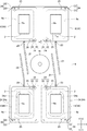
- FIG. 1 is a plan view of a part of a production system in which a processing apparatus according to a first embodiment of the present invention is incorporated.
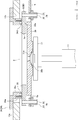
- 2 is a cross-sectional view taken along the line EE of FIG. It is an enlarged plan view of the mounting table and the rotary table shown in FIG. It is an enlarged view of the F section of FIG. It is an enlarged view of the G section of FIG.
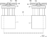
- FIG. 4 is a cross-sectional view taken along the line HH in FIG. 3.
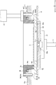
- FIG. 3 is a cross-sectional view of a portion of the JJ cross section of FIG. It is a partial expanded sectional view of the processing apparatus concerning Embodiment 2 of this invention. It is an enlarged view of the K section of FIG.
- FIG. 1 is a plan view of a part of a production system in which a processing apparatus 1 according to a first embodiment of the present invention is incorporated.
- 2 is a cross-sectional view taken along the line EE of FIG.
- the processing apparatus 1 of this embodiment is an inspection apparatus for inspecting an inspection object 2 that is a processing object.
- the inspection object 2 of the present embodiment is a liquid crystal panel
- the processing device 1 is an inspection device for inspecting the liquid crystal panel for lighting. Therefore, hereinafter, the processing apparatus 1 of this embodiment is referred to as “inspection apparatus 1”, and the inspection object 2 is referred to as “liquid crystal panel 2”.
- the liquid crystal panel 2 is formed in a rectangular flat plate shape.
- the liquid crystal panel 2 is a small liquid crystal panel used for, for example, a portable terminal.
- the liquid crystal panel 2 of this embodiment is a glass substrate on which a glass substrate or a polarizing plate is attached, and a backlight is not attached to the liquid crystal panel 2.
- the inspection device 1 is used by being incorporated in the production system of the liquid crystal panel 2.
- This production system includes a plurality of inspection apparatuses 1.
- two inspection apparatuses 1 are arranged with two conveyors 3 and two conveyors 4 formed in a straight line in between.
- the conveyors 3 and 4 are belt conveyors, for example.
- the inspection apparatus 1 is provided with a robot 5 that conveys the liquid crystal panel 2 between a mounting table 8 (described later) that constitutes the inspection apparatus 1 and the conveyors 3 and 4.
- the robot 5 sucks the liquid crystal panel 2 before inspection at the tip of the hand and conveys it from the conveyor 3 to the mounting table 8, and sucks the liquid crystal panel 2 after inspection at the tip of the hand and conveys it from the mounting table 8 to the conveyor. Transport to 4.
- the liquid crystal panel 2 before the inspection may be conveyed by the conveyor 4, and the liquid crystal panel 2 after the inspection may be conveyed by the conveyor 3.
- the inspection apparatus 1 includes a plurality of mounting tables 8 on which the liquid crystal panel 2 is mounted, a rotary table 9 on which the plurality of mounting tables 8 are mounted so as to be movable up and down, a rotation drive mechanism 10 that rotates the rotary table 9, and a rotation.
- An air cylinder 11 as a raising mechanism that raises the mounting table 8 with respect to the table 9, a backlight 12 that emits light from the back surface of the liquid crystal panel 2, a mounting table 8, a rotary table 9, a rotary drive mechanism 10, an air And a casing 13 in which the cylinder 11 and the backlight 12 are accommodated.
- the inspection apparatus 1 according to this embodiment includes four mounting tables 8. As shown in FIG. 2, the inspection apparatus 1 is installed on a gantry 14.
- the conveyance direction of the liquid crystal panel 2 by the conveyors 3 and 4 (X direction in FIG. 1 and the like) is referred to as “left and right direction”, and the direction perpendicular to the vertical direction and the left and right direction (Y direction in FIG. 1 and the like). Let it be the “front-rear direction”.
- the front-rear direction is a direction in which the two inspection devices 1 are arranged to face each other with the conveyors 3 and 4 sandwiched therebetween.
- the side where the conveyors 3 and 4 are arranged (Y1 direction side in FIG. 2 and the like) is referred to as the “front” side, and the opposite side (Y2 direction in FIG. 2 and the like). Side) is the “rear (back)” side.
- FIG. 3 is an enlarged plan view of the mounting table 8 and the rotary table 9 shown in FIG.
- FIG. 4 is an enlarged view of a portion F in FIG.
- FIG. 5 is an enlarged view of a portion G in FIG.
- FIG. 6 is a cross-sectional view taken along the line HH of FIG.
- FIG. 7 is a cross-sectional view of a portion of the JJ cross section of FIG.
- the turntable 9 is formed in a substantially rectangular flat plate shape.
- the turntable 9 is arranged so that the thickness direction of the turntable 9 matches the vertical direction.
- a rotation drive mechanism 10 is connected to the center of the rotary table 9.
- the rotation drive mechanism 10 is disposed below the rotary table 9.
- the rotation drive mechanism 10 includes a motor 17 and rotates the turntable 9 with the vertical direction as the axis direction of rotation.
- the motor 17 is connected to the rotary table 9 via a speed reducer 18, for example.
- a central portion of the rotary table 9 is fixed to the output shaft of the speed reducer 18 via a fixed plate 19 disposed on the upper side of the rotary table 9.
- the central portion of the rotary table 9 may be directly fixed to the output shaft of the motor 17.
- the motor 17 is, for example, a servo motor.
- Rotational drive mechanism 10 rotates rotary table 9 by 180 °. Specifically, the rotary table 9 is stopped in a state where the long side direction and the front-rear direction of the rotary table 9 formed in a substantially rectangular shape coincide with each other, and the rotary drive mechanism 10 rotates in this state. The table 9 is rotated 180 ° in one direction and stopped. Further, the rotary drive mechanism 10 stops the rotary table 9 that has been stopped by rotating 180 ° in one direction by rotating 180 ° in the opposite direction. For example, the rotary drive mechanism 10 stops the rotary table 9 in the state shown in FIG. 3 by rotating it 180 degrees clockwise (clockwise) and rotating it 180 degrees clockwise. 9 is turned 180 ° counterclockwise and stopped.
- the rotary table 9 has four through holes 9a penetrating in the vertical direction.
- the through hole 9a is formed in a substantially rectangular shape.
- the through hole 9 a is larger than the outer shape of the liquid crystal panel 2.
- the through hole 9a is formed so that the long side direction of the turntable 9 formed in a substantially rectangular shape matches the long side direction of the through hole 9a formed in a substantially rectangular shape. Yes.
- two through holes 9a are formed on each of both end sides of the turntable 9 in the long side direction.
- Two through-holes 9 a formed on both ends of the turntable 9 in the long side direction are arranged adjacent to each other in the short side direction of the turntable 9. That is, the four through holes 9a are arranged along the rotation direction of the turntable 9 when viewed from the up and down direction.
- a pair of through holes 9 a are formed at a 180 ° pitch with respect to the center of the turntable 9 (that is, the rotation center of the turntable 9). The distances between the centers of the four through holes 9a and the center of the turntable 9 are equal to each other.
- the mounting table 8 is formed in a substantially rectangular flat plate shape.
- the mounting table 8 is arranged so that the thickness direction of the mounting table 8 matches the vertical direction.
- the outer shape of the mounting table 8 is larger than the through hole 9a.
- a through hole 8 a that penetrates in the vertical direction is formed at the center of the mounting table 8.
- the through hole 8a is formed in a substantially rectangular shape.
- the through hole 8a is formed so that the long side direction of the mounting table 8 formed in a substantially rectangular shape matches the long side direction of the through hole 8a formed in a substantially rectangular shape.
- the through hole 8 a is slightly smaller than the outer shape of the liquid crystal panel 2.
- a plurality of suction holes are formed for sucking and holding the liquid crystal panel 2 mounted on the mounting table 8.
- An air suction hole connected to the suction hole is formed inside the mounting table 8, and one end of a pipe 21 is connected to the suction hole via a joint 20 (see FIG. 3). The other end of the pipe 21 is connected to an air suction mechanism such as a vacuum pump.
- the mounting table 8 is mounted on the rotary table 9 so that the center of the through hole 9a of the rotary table 9 and the center of the through hole 8a coincide with each other when viewed from above and below.
- the rotary table 9 is disposed along the rotational direction.
- a pair of mounting tables 8 are arranged at a 180 ° pitch with respect to the center of the rotary table 9 (that is, the rotation center of the rotary table 9).
- the distances between the centers of the four mounting tables 8 (centers of the through holes 8a) and the centers of the rotary table 9 (rotation center of the rotary table 9) are equal to each other.
- Guide pins 22 protruding downward are fixed to two corners on one diagonal line of the mounting table 8 formed in a substantially rectangular shape.
- a lower end portion of the guide pin 22 is inserted into a guide bush 23 that is fixed to the rotary table 9.
- the upper end portion of the guide bush 23 is inserted and fixed in a fixing hole formed in the rotary table 9, and the lower end portion of the guide bush 23 protrudes downward from the rotary table 9.
- the guide pin 22 and the guide bush 23 constitute a guide mechanism 24 that guides the mounting table 8 in the vertical direction with respect to the rotary table 9, and the mounting table 8 moves up and down with respect to the rotary table 9. It is possible.
- a spring holding pin 25 is fixed to the mounting table 8 so as to be adjacent to the guide pin 22 (see FIG. 6).
- the spring holding pin 25 protrudes downward from the mounting table 8.
- a flange portion 25 a is formed at the lower end of the spring holding pin 25.
- the lower end of the compression coil spring 26 is in contact with the upper surface of the flange portion 25a.
- the upper end portion of the compression coil spring 26 is disposed in a recess formed on the lower surface of the turntable 9.
- the mounting table 8 is urged downward by the urging force of the compression coil spring 26.
- the spring holding pin 25 and the compression coil spring 26 constitute a biasing mechanism 27 that biases the mounting table 8 downward.
- the turntable 9 is stopped in a state where the long side direction of the turntable 9 and the front-rear direction coincide with each other.
- two of the four mounting tables 8 are arranged at the inspection position 8A as a processing position where the lighting inspection of the liquid crystal panel 2 is performed, and the remaining ones.
- the two mounting tables 8 are arranged at a replacement position 8B where the liquid crystal panel 2 is unloaded from the mounting table 8 and the liquid crystal panel 2 is supplied to the mounting table 8.
- the position of the mounting table 8 when it is arranged behind the rotational drive mechanism 10 is the inspection position 8A, and the position of the mounting table 8 when it is arranged ahead of the rotational drive mechanism 10. Is the replacement position 8B.
- the mounting table 8 rotates around the center of the turntable 9 and moves between the inspection position 8A and the replacement position 8B. That is, when the turntable 9 rotates, the two mounting tables 8 arranged at the inspection position 8A among the four mounting tables 8 move to the replacement position 8B, and the remaining two arranged at the replacement position 8B. The individual mounting tables 8 move to the inspection position 8A.
- the piping 21 is routed so as not to hinder the rotation of the mounting table 8.
- the air cylinder 11 is disposed below each of the two mounting tables 8 disposed at the replacement position 8B. That is, as shown in FIG. 7, the inspection device 1 includes two air cylinders 11. The two air cylinders 11 are fixed to the housing 13 via a fixing bracket 29. The air cylinder 11 is arranged so that the rod of the air cylinder 11 protrudes upward. A blocking member 30 that closes the through hole 8 a of the mounting table 8 is attached to the tip (upper end) of the rod of the air cylinder 11 via a predetermined attachment member 31.
- the closing member 30 is formed in a substantially rectangular flat plate shape.
- the closing member 30 is arranged so that the thickness direction of the closing member 30 matches the vertical direction, and the long side direction of the closing member 30 formed in a substantially rectangular shape matches the front-rear direction. It is attached to the tip of the rod of the cylinder 11.
- a substantially quadrangular annular projecting portion 30 a that projects upward is formed on the outer peripheral end of the closing member 30.
- the protruding portion 30 a is formed so as to slightly protrude from the upper surface of the closing member 30 to the upper side.
- the outer shape of the closing member 30 is larger than the through hole 8a. Further, the outer shape of the closing member 30 is smaller than the through hole 9 a of the turntable 9. When viewed from the top-bottom direction, the center of the through hole 8a of the mounting table 8 arranged at the replacement position 8B and the center of the closing member 30 coincide. As shown in FIG. 5, a truncated cone-shaped recess 30 b is formed on the lower surface of the central portion of the closing member 30 so that the inner diameter gradually decreases toward the upper side. Further, on the upper surface side of the central portion of the mounting member 31, a convex curved portion 31a having an outer diameter gradually decreasing toward the upper side is formed, and the convex portion 31a is in contact with the concave portion 30b. . Therefore, it is possible to adjust the inclination of the closing member 30 with respect to the rod of the air cylinder 11 using the concave portion 30b and the convex portion 31a.
- the backlight 12 is disposed below the mounting table 8 disposed at the inspection position 8A. Specifically, the backlight 12 is disposed below the through holes 8a and 9a. On the upper side of the mounting table 8 arranged at the inspection position 8A, various devices for lighting inspection such as a plurality of cameras are arranged.
- the housing 13 is formed in a hollow box shape.
- the height of the rear portion of the housing 13 is higher than the height of the front portion of the housing 13.
- the housing 13 includes a bottom surface portion 13 a that forms the bottom surface of the housing 13, two side surface portions 13 b that form the left and right side surfaces of the housing 13, and a first top surface that forms the top surface of the front portion of the housing 13.
- Part 13c, second upper surface part 13d constituting the upper surface of the rear side part of housing 13, rear surface part 13e constituting the rear surface of housing 13, front end side of bottom surface part 13a and front end of first upper surface part 13c
- a first front surface portion 13g that connects the rear end of the first upper surface portion 13c and the front end of the second upper surface portion 13d.
- the first upper surface portion 13c and the second upper surface portion 13d are formed in a flat plate shape orthogonal to the vertical direction.
- the first upper surface portion 13c is disposed below the second upper surface portion 13d. Further, the first upper surface portion 13 c is disposed slightly above the mounting table 8 mounted on the rotary table 9.
- the mounting table 8 at the replacement position 8B is disposed below the first upper surface portion 13c.
- the mounting table 8 at the inspection position 8A is disposed below the second upper surface portion 13d, and various lighting inspection devices such as the backlight 12 and the camera are disposed below the second upper surface portion 13d.
- Equipment is arranged. That is, the portion of the housing 13 where the second upper surface portion 13d is disposed is an inspection portion where a lighting inspection is performed, and the portion where the first upper surface portion 13c is disposed is replaced with the liquid crystal panel 2. It is a replacement department.
- a through hole 13h penetrating in the vertical direction is formed in the first upper surface portion 13c.
- the through hole 13h is formed in a substantially rectangular shape.
- the through hole 13h is formed so that the long side direction of the through hole 13h formed in a substantially rectangular shape matches the front-rear direction.
- the through hole 13h is formed on the upper side of each of the two mounting tables 8 arranged at the replacement position 8B. That is, two through holes 13h are formed in the first upper surface portion 13c.
- the through hole 13 h is smaller than the outer shape of the mounting table 8. Further, the through hole 13 h is larger than the through hole 8 a of the mounting table 8.
- the housing 13 includes two guide members 34 formed in a substantially rectangular tube shape with a flat hook.
- the guide member 34 includes a substantially square tubular portion 34a and a flange portion 34b connected to the upper end of the tubular portion 34a.
- the guide member 34 is fixed to the first upper surface portion 13c in a state where the tube portion 34a is inserted into the through hole 13h and the lower surface of the flange portion 34b is in contact with the upper surface of the first upper surface portion 13c. That is, the guide member 34 is fixed to the first upper surface portion 13c so as to border the through hole 13h.
- the inner peripheral side of the guide member 34 is a substantially rectangular opening 34c.
- the guide member 34 is arranged so that the long side direction of the opening 34c formed in a substantially rectangular shape coincides with the front-rear direction.
- the opening 34 c is larger than the through hole 8 a of the mounting table 8. Further, the opening 34c is larger than the outer shape of the liquid crystal panel 2, and the liquid crystal panel 2 can pass through the opening 34c in the vertical direction.
- the opening part 34c is arrange
- the guide member 34 has a function of guiding the liquid crystal panel 2 to the mounting table 8.
- the lower end portion of the cylindrical portion 34a is a quadrangular annular convex portion 34d that projects downward from the lower surface of the first upper surface portion 13c (see FIG. 5). That is, a convex portion 34d that protrudes downward is formed at the edge of the opening 34c. A concave portion formed in a substantially square ring shape is formed on the lower end surface of the convex portion 34d.
- An annular seal member 35 that comes into contact with the upper surface of the mounting table 8 lifted by the air cylinder 11 is attached to the recess (see FIG. 5).
- the seal member 35 is an O-ring.
- the protrusion 30a of the closing member 30 and the seal member 35 overlap each other when viewed from the up-down direction.
- the air cylinder 11 is raised and the mounting table 8 disposed at the replacement position 8 ⁇ / b> B is lifted.
- the protrusion 30 a of the closing member 30 that has passed through the through hole 9 a contacts the lower surface of the mounting table 8 to lift the mounting table 8, and the upper surface of the mounting table 8 is a sealing member.
- the protruding portion 30 a lifts the mounting table 8 until it comes into contact with 35.
- the closing member 30 closes the through hole 8a of the mounting table 8, and the mounting table 8 and the closing member 30 close the opening 34c.
- the inside of the housing 13 becomes a sealed space, and the inside of the housing 13 Becomes a darkroom. That is, when the mounting table 8 arranged at the replacement position 8B is lifted by the air cylinder 11, the opening 34c is closed from the inside of the housing 13, and the inside of the housing 13 becomes a sealed space. Further, when the mounting table 8 disposed at the replacement position 8B is lifted by the air cylinder 11, the opening 34c is closed from the inside of the housing 13, and the inside of the housing 13 becomes a dark room.
- the lighting test of the liquid crystal panel 2 is performed in a state where the inside of the housing 13 is a dark room. At this time, the backlight 12 irradiates light through the through holes 8a and 9a to the liquid crystal panel 2 mounted on the mounting table 8 disposed at the inspection position 8A.
- the liquid crystal panel 2 mounted on the mounting table 8 disposed at the replacement position 8B is disposed in the opening 34c. It is exposed outside the housing 13.
- the robot 5 is the liquid crystal panel 2 after the lighting inspection disposed in the opening 34c (the placement table disposed at the replacement position 8B).
- the liquid crystal panel 2) placed on 8 is adsorbed and placed on the carry-out conveyor 4. Further, the robot 5 sucks and conveys the liquid crystal panel 2 before the inspection on the conveyor 3, and places it on the mounting table 8 after the liquid crystal panel 2 after the lighting inspection is carried out.
- the air cylinder 11 When the lighting inspection of the liquid crystal panel 2 is completed inside the housing 13 and the replacement of the liquid crystal panel 2 with respect to the mounting table 8 disposed at the replacement position 8B is completed, the air cylinder 11 is lowered. When the air cylinder 11 is lowered, the mounting table 8 disposed at the replacement position 8B is lowered by the urging force of the compression coil spring 26. When the mounting table 8 disposed at the replacement position 8B is lowered, the motor 17 is activated, the rotary table 9 rotates, and the mounting table 8 disposed at the inspection position 8A is moved to the replacement position 8B, and is moved to the replacement position 8B. The placed mounting table 8 moves to the inspection position 8A.
- the turntable 9 rotates and the mounting table 8 moves between the inspection position 8A and the replacement position 8B, similarly, the mounting table 8 placed at the replacement position 8B is lifted to close the opening 34c, and the inspection is performed.
- the lighting inspection of the liquid crystal panel 2 placed on the placing table 8 placed at the position 8A and the replacement of the liquid crystal panel 2 placed on the placing table 8 placed at the replacement position 8B are performed.
- the closing member 30 is lowered to a position where it does not interfere with the rotating rotary table 9.
- the opening 34c through which the liquid crystal panel 2 can pass is formed in the first upper surface portion 13c of the housing 13, but the mounting table 8 disposed at the replacement position 8B is lifted. Then, the opening 34c is closed from the inside of the housing 13, and the inside of the housing 13 becomes a sealed space, and the inside of the housing 13 becomes a dark room. Further, in this embodiment, when the mounting table 8 disposed at the replacement position 8B is lifted, the liquid crystal panel 2 mounted on the mounting table 8 disposed at the replacement position 8B is disposed in the opening 34c. It is exposed outside the housing 13.
- the seal member 35 is attached to the lower end surface of the projection 34d formed at the edge of the opening 34c, and the upper surface of the mounting table 8 lifted by the air cylinder 11 contacts the seal member 35. Therefore, in this embodiment, when the mounting table 8 arranged at the replacement position 8B is lifted by the air cylinder 11, it is possible to improve the sealing property of the space inside the housing 13.
- the protrusion 30a of the closing member 30 and the seal member 35 overlap each other when viewed from above and below, so that the adhesion between the seal member 35 and the upper surface of the mounting table 8 can be improved.
- the closing member 30 is attached to the tip of the rod of the air cylinder 11, and when the mounting table 8 arranged at the replacement position 8 ⁇ / b> B is lifted by the air cylinder 11, the through-hole of the mounting table 8 is opened by the closing member 30. 8a is blocked. Therefore, in this embodiment, even if the through hole 8a is formed in the mounting table 8, the inside of the housing 13 can be a sealed space and the inside of the housing 13 can be a dark room.
- FIG. 8 is an enlarged cross-sectional view of a part of the processing apparatus 1 according to the second embodiment of the present invention.
- FIG. 9 is an enlarged view of a portion K in FIG.
- the processing apparatus 1 of this embodiment is also an inspection apparatus for inspecting the liquid crystal panel 2. Therefore, hereinafter, the processing apparatus 1 of the present embodiment is referred to as “inspection apparatus 1”.
- the plurality of mounting tables 8 are mounted on the rotary table 9 so as to be movable up and down. However, in the present embodiment, the plurality of mounting tables 8 are mounted and fixed on the rotary table 9, and the inspection apparatus 1. Does not include the guide mechanism 24 and the biasing mechanism 27.
- the guide member 34 is fixed to the housing 13. However, in this embodiment, the guide member 34 is held by the housing 13 so as to be movable up and down. An air cylinder 41 for raising and lowering the member 34 is provided.
- FIG. 8 and FIG. 9 the same reference numerals are given to the configurations common to the configuration of the inspection apparatus 1 of the first embodiment. In the following, description of the configuration common to the configuration of the inspection apparatus 1 of the first embodiment is omitted or simplified.
- a plurality of mounting tables 8 are mounted on the rotary table 9 and fixed.
- the air cylinder 11 is provided below each of the two mounting tables 8 arranged at the replacement position 8B as in the first embodiment. Has been placed.
- a closing member 30 that closes the through hole 8 a from the lower side of the mounting table 8 is attached to the tip (upper end) of the rod of the air cylinder 11 via an attachment member 31. That is, the closing member 30 is disposed below the mounting table 8 disposed at the replacement position 8B, and the closing member 30 is accommodated in the housing 13.
- the air cylinder 11 of this embodiment is a closing member lifting mechanism that lifts and lowers the closing member 30.
- the guide member 34 is held by the housing 13 so as to be movable up and down. Specifically, the guide member 34 is held on the first upper surface portion 13c of the housing 13 so as to be movable up and down.
- the cylindrical portion 34a of the guide member 34 formed in a substantially square tube shape with a flat hook is inserted into a through hole 13h formed in the first upper surface portion 13c.
- the through hole 13h is slightly larger than the outer shape of the cylindrical portion 34a.
- the flange portion 34b of the guide member 34 is disposed on the upper side of the first upper surface portion 13c.
- the guide member 34 of this embodiment is an elevating member that is held by the housing 13 so as to be movable up and down, and the through hole 13h is a housing side through hole in which a lower end side portion of the guide member 34 that is the elevating member is disposed.
- a guide pin 42 protruding downward is fixed to two corners on one diagonal line of the flange 34b.
- the lower end portion of the guide pin 42 is inserted through a guide bush 43 that is fixed to the first upper surface portion 13c.
- the lower end portion of the guide bush 43 is inserted and fixed in a fixing hole formed in the first upper surface portion 13c.
- the guide pin 42 and the guide bush 43 constitute a guide mechanism 44 that guides the guide member 34 in the vertical direction with respect to the first upper surface portion 13c.
- the air cylinder 41 is fixed to the front surface of the second front surface portion 13 g and is disposed outside the housing 13.
- the air cylinder 41 is disposed so that the rod of the air cylinder 41 protrudes downward.
- the tip (lower end) of the rod of the air cylinder 41 is fixed to the upper surface of the flange portion 34b.
- the tip of the rod of the air cylinder 41 is fixed to each of the two guide members 34. That is, the inspection apparatus 1 includes two air cylinders 41.
- the air cylinder 41 of this embodiment is a lifting member lifting mechanism that lifts and lowers a guide member 34 that is a lifting member. Note that the tips of the rods of one air cylinder 41 may be fixed to the two guide members 34 via predetermined members.
- the inner peripheral side of the guide member 34 is a substantially rectangular opening 34c.
- the opening 34 c is larger than the through hole 8 a of the mounting table 8. Further, the opening 34c is larger than the outer shape of the liquid crystal panel 2, and the liquid crystal panel 2 can pass through the opening 34c in the vertical direction.
- the opening part 34c is arrange
- the guide member 34 includes a seal member 45 attached to the lower end surface of the guide member 34 (that is, the lower end surface of the cylindrical portion 34a) (see FIG. 9). Specifically, a concave portion formed in a substantially square ring shape is formed on the lower end surface of the cylindrical portion 34a, and an annular seal member 45 is attached in the concave portion.
- the seal member 45 is an O-ring. The seal member 45 contacts the upper surface of the mounting table 8 when the guide member 34 is lowered.
- a concave portion formed in a substantially square ring shape is formed on the edge of the through hole 13h on the upper surface of the first upper surface portion 13c, and in this concave portion, the flange portion 34b (that is, the lowered guide member 34)
- a seal member 46 as a second seal member that contacts the upper end portion of the guide member 34 is attached (see FIG. 9). That is, the seal member 46 is attached to the edge of the through hole 13h on the upper surface of the first upper surface portion 13c.
- the seal member 46 is an O-ring.
- the rod of the air cylinder 11 is raised and the rod of the air cylinder 41 is lowered. That is, when the lighting inspection of the liquid crystal panel 2 is performed, the closing member 30 is lifted to close the through hole 8a of the mounting table 8 placed at the replacement position 8B, and the guide member 34 is lowered to be placed at the replacement position 8B.
- the mounting table 8 is contacted. Specifically, as shown in FIG. 9, the protruding portion 30a of the closing member 30 contacts the lower surface of the mounting table 8 to close the through hole 8a, and a seal member 45 attached to the lower end surface of the cylindrical portion 34a is mounted. It contacts the upper surface of the mounting table 8. When the guide member 34 is lowered, the seal member 46 comes into contact with the lower surface of the flange portion 34b.
- the seal member 45 attached to the lower end surface of the cylindrical portion 34a contacts the upper surface of the mounting table 8, and the seal member 46 contacts the lower surface of the flange portion 34b.
- the inside of the housing 13 is a sealed space, and the inside of the housing 13 is a dark room. That is, when the closing member 30 is lifted to close the through hole 8a of the mounting table 8 disposed at the replacement position 8B, and the guide member 34 is lowered to contact the mounting table 8 disposed at the replacement position 8B, the mounting table 8 and the closing member 30 close the opening 34c from the inside of the housing 13, and the inside of the housing 13 becomes a sealed space and a dark room.
- the lighting inspection of the liquid crystal panel 2 is performed in a state where the inside of the housing 13 is a dark room.
- the replacement position is reached.
- the liquid crystal panel 2 mounted on the mounting table 8 disposed in 8B is disposed in the opening 34c and exposed outside the housing 13.
- the robot 5 is the liquid crystal panel 2 after the lighting inspection disposed in the opening 34c (the placement table disposed at the replacement position 8B).
- the liquid crystal panel 2) placed on 8 is adsorbed and placed on the carry-out conveyor 4. Further, the robot 5 sucks and conveys the liquid crystal panel 2 before the inspection on the conveyor 3, and places it on the mounting table 8 after the liquid crystal panel 2 after the lighting inspection is carried out.
- the rod of the air cylinder 11 is lowered and the closing member 30 is moved.
- the rod descends, the rod of the air cylinder 41 rises, and the guide member 34 rises.
- the motor 17 is activated, the rotary table 9 rotates, the mounting table 8 disposed at the inspection position 8A moves to the replacement position 8B, and the mounting table 8 disposed at the replacement position 8B moves to the inspection position 8A.
- the closing member 30 rises to close the through hole 8a of the mounting table 8 disposed at the replacement position 8B, and the guide member 34 descends to contact the mounting table 8 disposed at the replacement position 8B. Then, the inside of the housing 13 becomes a sealed space to become a dark room, and the liquid crystal panel 2 placed on the placing table 8 placed at the replacement position 8B is placed in the opening 34c and placed in the housing. Since it is exposed to the outside of the body 13, it is possible to perform lighting inspection of the liquid crystal panel 2 in a dark room and replacement of the liquid crystal panel 2 with respect to the mounting table 8 together.
- the mounting table 8 since the mounting table 8 is fixed to the rotary table 9, the mounting table disposed at the inspection position 8 ⁇ / b> A as compared with the case where the mounting table 8 is mounted on the rotary table 9 so as to be movable up and down. Accordingly, it is possible to suppress a relative position shift between the liquid crystal panel 2 placed on the apparatus 8 and various devices for lighting inspection. Therefore, in this embodiment, it is possible to improve the accuracy of the lighting inspection of the liquid crystal panel 2. Further, since the mounting table 8 is fixed to the rotary table 9, the pipe 21 does not move up and down together with the mounting table 8.
- the configuration of the inspection apparatus 1 is complicated as compared with the first embodiment.
- the configuration of the inspection apparatus 1 is complicated as compared with the first embodiment.
- the seal member 45 since the seal member 45 needs to be brought into contact with the upper surface of the mounting table 8 and the seal member 46 needs to be brought into contact with the lower surface of the flange portion 34b, the seal member 45 is relatively low in hardness and easily deforms elastically. 46 need to be used.
- the through hole 8a is formed in the mounting table 8.
- the through hole 8a is formed in the mounting table 8. May not be formed.
- the closing member 30 may not be attached to the tip of the rod of the air cylinder 11. In this case, when the mounting table 8 disposed at the replacement position 8B is lifted by the air cylinder 11, the mounting table 8 closes the opening 34c.
- the inspection device 1 may not include the air cylinder 11 and the closing member 30. In this case, when the guide member 34 descends and comes into contact with the mounting table 8 disposed at the replacement position 8B, the opening 34c is blocked from the inside of the housing 13 by the mounting table 8.
- a seal member similar to the seal member 35 may be attached to the upper end surface of the protrusion 30a.
- the seal member 35 may not be attached to the lower end surface of the convex portion 34d.
- the seal member 45 may not be attached to the lower end surface of the cylindrical portion 34a, and the seal member 46 is attached to the edge of the through hole 13h on the upper surface of the first upper surface portion 13c. It is not necessary.
- the raising mechanism that raises the mounting table 8 may be a motor as a drive source, for example.
- the closing member lifting mechanism that lifts and lowers the closing member 30 may be, for example, a motor as a drive source.
- the urging mechanism 27 may not be provided. In this case, when the air cylinder 11 is lowered, the mounting table 8 is lowered by its own weight.
- the pair of mounting tables 8 are arranged at a pitch of 180 ° with respect to the rotation center of the rotary table 9.
- the mounting tables 8 may be arranged at a 180 ° pitch, or three or more mounting tables 8 and the three or more mounting tables 8 may be arranged at a 180 ° pitch.
- the number of guide members 34 corresponding to the number of the mounting tables 8 is installed, and the number of openings 34 c corresponding to the number of the mounting tables 8 is formed in the housing 13.
- the number of air cylinders 11 corresponding to the number of mounting tables 8 is installed.
- the number of air cylinders 41 corresponding to the number of mounting tables 8 is installed.
- the pair of mounting tables 8 are arranged at two positions with a 180 ° pitch with respect to the rotation center of the rotary table 9. It may be arranged at three or more places at a predetermined angular pitch.
- the pair of mounting tables 8 may be arranged at a 120 ° pitch with respect to the rotation center of the rotary table 9. In this case, for example, the turntable 9 rotates by 120 ° and stops. In this case, the replacement position where the liquid crystal panel 2 is unloaded from the mounting table 8 and the replacement position where the liquid crystal panel 2 is supplied to the mounting table 8 may be different.
- the pair of mounting tables 8 includes an inspection position 8A, a replacement position where the liquid crystal panel 2 is unloaded from the mounting table 8, and a liquid crystal panel to the mounting table 8 when the rotary table 9 rotates 120 °. 2 sequentially move to the replacement position where the supply of 2 is performed.
- the configuration of the inspection apparatus 1 is simplified. It becomes possible. Further, when the pair of mounting tables 8 are disposed at three or more positions at a predetermined angular pitch with respect to the rotation center of the turntable 9, the mounting tables are not disposed at either the inspection position 8A or the replacement position. There may be eight.
- the lighting inspection of the liquid crystal panel 2 is performed in the dark room inside the housing 13, but the lighting inspection of an inspection object other than the liquid crystal panel 2 may be performed in the dark room inside the housing 13.
- the processing apparatus 1 is an inspection apparatus for inspecting lighting of the liquid crystal panel 2
- the processing apparatus to which the present invention is applied processes a predetermined processing object other than the inspection apparatus. It may be a device.
- the processing apparatus to which the present invention is applied may be an ultraviolet irradiation apparatus.
- the processing target to be processed by the ultraviolet irradiation device is an irradiation target irradiated with ultraviolet rays.
- the same position as the inspection position 8A in the above-described form is an irradiation position at which the irradiation target is irradiated with ultraviolet rays, and the rotary table 9 is placed between the irradiation position and the replacement position 8B.
- an irradiation unit for irradiating ultraviolet rays is disposed inside the housing 13 and above the mounting table 8 disposed at the irradiation position. Further, in this case, in the first embodiment, the mounting table 8 disposed at the replacement position 8B is lifted and the opening 34c so that the ultraviolet rays irradiated to the irradiation target do not leak outside the housing 13.
- the irradiation target is irradiated with ultraviolet rays in a state where the inside of the housing 13 is a sealed space.
- the through-hole 8a of the mounting table 8 that is disposed at the replacement position 8B is raised by the closing member 30 so that the ultraviolet rays irradiated to the irradiation target do not leak outside the housing 13. Irradiation is performed in a state where the guide member 34 is lowered and comes into contact with the mounting table 8 disposed at the replacement position 8B to close the opening 34c, and the inside of the housing 13 becomes a sealed space.
- the object is irradiated with ultraviolet rays.
- the irradiation object exposed outside the housing 13 is replaced with respect to the mounting table 8 disposed at the replacement position 8B while irradiating the irradiation object disposed at the irradiation position with ultraviolet rays. It becomes possible to do. That is, it is possible to perform irradiation of ultraviolet rays onto the irradiation object in the sealed space and replacement of the irradiation object with respect to the mounting table 8 together. Therefore, even when the irradiation object is irradiated with ultraviolet rays in the sealed space, the time required for the irradiation process of the ultraviolet rays onto the irradiation object can be shortened.
Landscapes
- Physics & Mathematics (AREA)
- Nonlinear Science (AREA)
- General Physics & Mathematics (AREA)
- Chemical & Material Sciences (AREA)
- General Health & Medical Sciences (AREA)
- Biochemistry (AREA)
- Analytical Chemistry (AREA)
- Life Sciences & Earth Sciences (AREA)
- Immunology (AREA)
- Pathology (AREA)
- Crystallography & Structural Chemistry (AREA)
- Health & Medical Sciences (AREA)
- Optics & Photonics (AREA)
- Liquid Crystal (AREA)
Abstract
この処理装置は、たとえば、処理対象物2が載置される複数の載置台8と、複数の載置台8が搭載される回転テーブル9と、載置台8等が収容される筐体13とを備え、いくつかの載置台8は、処理対象物2の処理が行われる処理位置8Aに配置され、いくつかの載置台8は、処理対象物8の入替が行われる入替位置8Bに配置されている。筐体13には、入替位置8Bに配置される載置台8の上側に配置される開口部34cが形成され、入替位置8Bに配置される載置台8の下側には、載置台8を上昇させる上昇機構11が配置されている。入替位置8Bに配置される載置台8が持ち上げられると、開口部34cが塞がれて筐体13の内部が密閉された空間になるとともに、処理対象物2が筐体13の外側に露出する。
Description
本発明は、所定の処理対象物を処理する処理装置に関する。
従来、液晶パネルの検査を行う検査装置が知られている(たとえば、特許文献1参照)。特許文献1に記載の検査装置は、液晶パネルの製造処理工程の途中に組み込まれている。この検査装置は、液晶パネルの点灯検査を行うプローバと、検査前の液晶パネルをプローバに向かって搬送する搬入側コンベヤと、搬入側コンベヤで搬送された液晶パネルをプローバに搬入する搬入機構と、検査後の液晶パネルをプローバから搬出する搬出機構と、搬出機構によって搬出された液晶パネルを搬送する搬出側コンベヤとを備えている。
特許文献1に記載の検査装置では、プローバは、液晶パネルが載置されるワークテーブルと、液晶パネルの背面から液晶パネルに光を照射するバックライトと、液晶パネルの表面の映像が映し出されるスクリーンと、ワークテーブルとスクリーンとの間に配置される光学系等を備えており、これらの構成は、筐体の中に配置されている。筐体には、搬入機構による液晶パネルの搬入を行う際に開閉するシャッタと、搬出機構による液晶パネルの搬出を行う際に開閉するシャッタとが設けられている。
特許文献1に記載の検査装置では、シャッタが閉まると、筐体の内部が密閉された空間となり、外部からの光が遮断された暗室になる。液晶パネルの点灯検査は、シャッタが閉じている状態の筐体の中で行われ(すなわち、暗室となっている筐体の内部で行われ)、液晶パネルの点灯検査が終了すると、シャッタが開いて、検査後の液晶パネルがワークテーブルから搬出されるとともに、検査前の液晶パネルがワークテーブルに搬入される。また、検査前の液晶パネルがワークテーブルに搬入されるとシャッタが閉じ、暗室となった筐体の内部で、次の液晶パネルの点灯検査が行われる。すなわち、特許文献1に記載の検査装置では、液晶パネルの点灯検査と、ワークテーブルに対する液晶パネルの入替とが交互に行われている。
特許文献1に記載の検査装置が組み込まれる液晶パネルの生産システムでは、液晶パネルの生産効率を高めるために、暗室となっている筐体の内部で点灯検査を行う検査工程に要する時間が短い方が好ましい。すなわち、この生産システムでは、密閉空間の中で点灯検査を行う検査工程に要する時間は短い方が好ましい。しかしながら、特許文献1に記載の検査装置では、液晶パネルの点灯検査とワークテーブルに対する液晶パネルの入替とが交互に行われているため、密閉空間の中で点灯検査を行う検査工程に要する時間が長くなる。
そこで、本発明の課題は、密閉空間の中で処理対象物に対して所定の処理を行う場合であっても、密閉空間の中で処理対象物を処理する処理工程に要する時間を短縮することが可能な処理装置を提供することにある。
上記の課題を解決するため、本発明の処理装置は、処理対象物が載置される複数の載置台と、複数の載置台が昇降可能に搭載される回転テーブルと、上下方向を回転の軸方向として回転テーブルを回転させる回転駆動機構と、回転テーブルに対して載置台を上昇させる上昇機構と、載置台、回転テーブル、回転駆動機構および上昇機構が収容される筐体とを備え、複数の載置台のうちのいくつかの載置台は、処理対象物の処理が行われる処理位置に配置され、複数の載置台のうちのいくつかの載置台は、載置台からの処理対象物の搬出および載置台への処理対象物の供給の少なくともいずれか一方が行われる入替位置に配置され、回転テーブルは、処理位置と入替位置との間で載置台を移動させ、筐体には、入替位置に配置される載置台の上側に配置されるとともに処理対象物が通過可能な開口部が形成され、上昇機構は、入替位置に配置される載置台の下側に配置され、入替位置に配置される載置台が上昇機構によって持ち上げられると、筺体の内部から開口部が塞がれて筐体の内部が密閉された空間になるとともに、処理対象物が開口部の中に配置されて筐体の外側に露出することを特徴とする。
本発明の処理装置では、複数の載置台のうちのいくつかの載置台は、処理対象物の処理が行われる処理位置に配置され、複数の載置台のうちのいくつかの載置台は、載置台からの処理対象物の搬出および載置台への処理対象物の供給の少なくともいずれか一方が行われる入替位置に配置されている。また、本発明では、処理対象物が通過可能な開口部が筐体に形成されており、入替位置に配置される載置台が上昇機構によって持ち上げられると、筺体の内部から開口部が塞がれて筐体の内部が密閉された空間になるとともに、処理対象物が開口部の中に配置されて筐体の外側に露出する。
そのため、本発明では、処理位置に配置された載置台に載置される処理対象物に対して密閉空間の中で処理を行いながら、入替位置に配置される載置台に対して、筐体の外側に露出する処理対象物の入替を行うことが可能になる。すなわち、本発明では、密閉空間の中での処理対象物の処理と、載置台に対する処理対象物の入替とを一緒に行うことが可能になる。したがって、本発明では、密閉空間の中で処理対象物に対して処理を行う場合であっても、密閉空間の中で処理対象物を処理する処理工程に要する時間を短縮することが可能になる。
本発明において、たとえば、処理対象物は、点灯検査される検査対象物であり、複数の載置台のうちのいくつかの載置台は、検査対象物の点灯検査が行われる処理位置としての検査位置に配置され、複数の載置台のうちのいくつかの載置台は、入替位置に配置され、回転テーブルは、検査位置と入替位置との間で載置台を移動させ、入替位置に配置される載置台が上昇機構によって持ち上げられると、開口部が塞がれて、筐体の内部が暗室になる。この場合には、検査位置に配置された載置台に載置される検査対象物を暗室の中で点灯検査しながら、入替位置に配置される載置台に対して、筐体の外側に露出する検査対象物の入替を行うことが可能になる。すなわち、暗室の中での検査対象物の点灯検査と、載置台に対する検査対象物の入替とを一緒に行うことが可能になる。したがって、暗室の中で検査対象物の点灯検査を行う場合であっても、検査対象物の検査工程に要する時間を短縮することが可能になる。
本発明において、たとえば、処理対象物は、紫外線が照射される照射対象物であり、複数の載置台のうちのいくつかの載置台は、照射対象物に紫外線が照射される処理位置としての照射位置に配置され、複数の載置台のうちのいくつかの載置台は、入替位置に配置され、回転テーブルは、照射位置と入替位置との間で載置台を移動させる。この場合には、照射位置に配置された載置台に載置される照射対象物に対して紫外線を照射しながら、入替位置に配置される載置台に対して、筐体の外側に露出する照射対象物の入替を行うことが可能になる。すなわち、密閉空間の中での照射対象物への紫外線の照射と、載置台に対する照射対象物の入替とを一緒に行うことが可能になる。したがって、密閉空間の中で照射対象物への紫外線の照射を行う場合であっても、照射対象物への紫外線の照射工程に要する時間を短縮することが可能になる。
本発明において、入替位置では、載置台からの処理対象物の搬出および載置台への処理対象物の供給が行われることが好ましい。このように構成すると、載置台への処理対象物の供給が行われる入替位置と、載置台からの処理対象物の搬出が行われる入替位置とが別々になっている場合と比較して、処理装置の構成を簡素化することが可能になる。
本発明において、開口部の縁には、下側に向かって突出する環状の凸部が形成され、凸部の下端面には、載置台の上面に接触する環状のシール部材が取り付けられていることが好ましい。このように構成すると、入替位置に配置される載置台が上昇機構によって持ち上げられたときに、筐体の内部の空間の密閉性を高めることが可能になる。
本発明において、たとえば、載置台には、上下方向に貫通する貫通穴が形成され、上昇機構には、貫通穴を塞ぐ閉塞部材が取り付けられ、入替位置に配置される載置台が上昇機構によって持ち上げられると、閉塞部材によって貫通穴が塞がれるとともに、載置台と閉塞部材とによって開口部が塞がれる。この場合には、上下方向に貫通する貫通穴が載置台に形成されていても、筐体の内部を密閉された空間にすることが可能になる。
本発明において、入替位置に配置される載置台が上昇機構によって持ち上げられると、載置台によって開口部が塞がれても良い。
また、上記の課題を解決するため、本発明の処理装置は、上下方向に貫通する貫通穴が形成されるとともに処理対象物が載置される複数の載置台と、複数の載置台が搭載される回転テーブルと、上下方向を回転の軸方向として回転テーブルを回転させる回転駆動機構と、載置台の下側から貫通穴を塞ぐ閉塞部材と、閉塞部材を昇降させる閉塞部材昇降機構と、載置台、回転テーブル、回転駆動機構、閉塞部材および閉塞部材昇降機構が収容される筐体と、筺体に昇降可能に保持される昇降部材と、昇降部材を昇降させる昇降部材昇降機構とを備え、複数の載置台のうちのいくつかの載置台は、処理対象物の処理が行われる処理位置に配置され、複数の載置台のうちのいくつかの載置台は、載置台からの処理対象物の搬出および載置台への処理対象物の供給の少なくともいずれか一方が行われる入替位置に配置され、回転テーブルは、処理位置と入替位置との間で載置台を移動させ、昇降部材は、搬送対象物が通過可能な開口部を内周側に有する筒状に形成されるとともに、入替位置に配置される載置台の上側に配置され、閉塞部材は、入替位置に配置される載置台の下側に配置され、閉塞部材が上昇して入替位置に配置される載置台の貫通穴を塞ぐとともに昇降部材が下降して入替位置に配置される載置台に接触すると、筺体の内部から開口部が塞がれて筐体の内部が密閉された空間になるとともに、処理対象物が開口部の中に配置されて筐体の外側に露出することを特徴とする。
本発明の処理装置では、複数の載置台のうちのいくつかの載置台は、処理対象物の処理が行われる処理位置に配置され、複数の載置台のうちのいくつかの載置台は、載置台からの処理対象物の搬出および載置台への処理対象物の供給の少なくともいずれか一方が行われる入替位置に配置されている。また、本発明では、載置台に形成される貫通穴を載置台の下側から塞ぐ閉塞部材が、入替位置に配置される載置台の下側に配置され、筺体に昇降可能に保持される昇降部材が、入替位置に配置される載置台の上側に配置されている。さらに、本発明では、処理対象物が通過可能な開口部が昇降部材に形成されており、閉塞部材が上昇して入替位置に配置される載置台の貫通穴を塞ぐとともに昇降部材が下降して入替位置に配置される載置台に接触すると、筺体の内部から開口部が塞がれて筐体の内部が密閉された空間になるとともに、処理対象物が開口部の中に配置されて筐体の外側に露出する。
そのため、本発明では、処理位置に配置された載置台に載置される処理対象物に対して密閉空間の中で処理を行いながら、入替位置に配置される載置台に対して、筐体の外側に露出する処理対象物の入替を行うことが可能になる。すなわち、本発明では、密閉空間の中での処理対象物の処理と、載置台に対する処理対象物の入替とを一緒に行うことが可能になる。したがって、本発明では、密閉空間の中で処理対象物に対して処理を行う場合であっても、密閉空間の中で処理対象物を処理する処理工程に要する時間を短縮することが可能になる。
本発明において、たとえば、処理対象物は、点灯検査される検査対象物であり、複数の載置台のうちのいくつかの載置台は、検査対象物の点灯検査が行われる処理位置としての検査位置に配置され、複数の載置台のうちのいくつかの載置台は、入替位置に配置され、回転テーブルは、検査位置と入替位置との間で載置台を移動させ、閉塞部材が上昇して入替位置に配置される載置台の貫通穴を塞ぐとともに昇降部材が下降して入替位置に配置される載置台に接触すると、開口部が塞がれて、筐体の内部が暗室になる。この場合には、検査位置に配置された載置台に載置される検査対象物を暗室の中で点灯検査しながら、入替位置に配置される載置台に対して、筐体の外側に露出する検査対象物の入替を行うことが可能になる。すなわち、暗室の中での検査対象物の点灯検査と、載置台に対する検査対象物の入替とを一緒に行うことが可能になる。したがって、暗室の中で検査対象物の点灯検査を行う場合であっても、検査対象物の検査工程に要する時間を短縮することが可能になる。
本発明において、筐体には、昇降部材の下端側部分が配置される筐体側貫通穴が形成され、昇降部材は、昇降部材の下端面に取り付けられ載置台の上面に接触する環状のシール部材を備え、筐体側貫通穴の縁には、下降した昇降部材の上端側部分に接触する環状の第2のシール部材が取り付けられていることが好ましい。このように構成すると、閉塞部材が上昇して入替位置に配置される載置台の貫通穴を塞ぐとともに昇降機構が下降して入替位置に配置される載置台に接触したときに、筐体の内部の空間の密閉性を高めることが可能になる。
さらに、上記の課題を解決するため、本発明の処理装置は、処理対象物が載置される複数の載置台と、複数の載置台が搭載される回転テーブルと、上下方向を回転の軸方向として回転テーブルを回転させる回転駆動機構と、載置台、回転テーブルおよび回転駆動機構が収容される筐体と、筺体に昇降可能に保持される昇降部材と、昇降部材を昇降させる昇降部材昇降機構とを備え、複数の載置台のうちのいくつかの載置台は、処理対象物の処理が行われる処理位置に配置され、複数の載置台のうちのいくつかの載置台は、載置台からの処理対象物の搬出および載置台への処理対象物の供給の少なくともいずれか一方が行われる入替位置に配置され、回転テーブルは、処理位置と入替位置との間で載置台を移動させ、昇降部材は、搬送対象物が通過可能な開口部を内周側に有する筒状に形成されるとともに、入替位置に配置される載置台の上側に配置され、昇降部材が下降して入替位置に配置される載置台に接触すると、筺体の内部から開口部が塞がれて筐体の内部が密閉された空間になるとともに、処理対象物が開口部の中に配置されて筐体の外側に露出することを特徴とする。
本発明の処理装置では、複数の載置台のうちのいくつかの載置台は、処理対象物の処理が行われる処理位置に配置され、複数の載置台のうちのいくつかの載置台は、載置台からの処理対象物の搬出および載置台への処理対象物の供給の少なくともいずれか一方が行われる入替位置に配置されている。また、本発明では、筺体に昇降可能に保持される昇降部材が、入替位置に配置される載置台の上側に配置されている。さらに、本発明では、処理対象物が通過可能な開口部が昇降部材に形成されており、昇降部材が下降して入替位置に配置される載置台に接触すると、筺体の内部から開口部が塞がれて筐体の内部が密閉された空間になるとともに、処理対象物が開口部の中に配置されて筐体の外側に露出する。
そのため、本発明では、処理位置に配置された載置台に載置される処理対象物に対して密閉空間の中で処理を行いながら、入替位置に配置される載置台に対して、筐体の外側に露出する処理対象物の入替を行うことが可能になる。すなわち、本発明では、密閉空間の中での処理対象物の処理と、載置台に対する処理対象物の入替とを一緒に行うことが可能になる。したがって、本発明では、密閉空間の中で処理対象物に対して処理を行う場合であっても、密閉空間の中で処理対象物を処理する処理工程に要する時間を短縮することが可能になる。
以上のように、本発明の処理装置では、密閉空間の中で処理対象物に対して所定の処理を行う場合であっても、密閉空間の中で処理対象物を処理する処理工程に要する時間を短縮することが可能になる。
以下、図面を参照しながら、本発明の実施の形態を説明する。
[実施の形態1]
(処理装置の概略構成)
図1は、本発明の実施の形態1にかかる処理装置1が組み込まれる生産システムの一部分の平面図である。図2は、図1のE-E断面の断面図である。
(処理装置の概略構成)
図1は、本発明の実施の形態1にかかる処理装置1が組み込まれる生産システムの一部分の平面図である。図2は、図1のE-E断面の断面図である。
本形態の処理装置1は、処理対象物である検査対象物2を検査するための検査装置である。具体的には、本形態の検査対象物2は、液晶パネルであり、処理装置1は、液晶パネルを点灯検査するための検査装置である。したがって、以下では、本形態の処理装置1を「検査装置1」とし、検査対象物2を「液晶パネル2」とする。液晶パネル2は、長方形の平板状に形成されている。この液晶パネル2は、たとえば、携帯端末等に使用される小型の液晶パネルである。なお、本形態の液晶パネル2は、ガラス基板または偏光板が貼り付けられたガラス基板であり、液晶パネル2にはバックライトが取り付けられていない。
検査装置1は、液晶パネル2の生産システムに組み込まれて使用される。この生産システムは、複数の検査装置1を備えている。また、この生産システムでは、図1に示すように、2個の検査装置1が、直線状に形成される2個のコンベヤ3および2個のコンベヤ4を挟んだ状態で配置されている。コンベヤ3、4は、たとえば、ベルトコンベヤである。
コンベヤ3では、たとえば、検査装置1で検査される前の液晶パネル2が搬送され、コンベヤ4では、検査装置1で検査された後の液晶パネル2が搬送される。2個のコンベヤ3は、2個のコンベヤ4の間に挟まれている。また、検査装置1には、検査装置1を構成する後述の載置台8とコンベヤ3、4との間で液晶パネル2を搬送するロボット5が取り付けられている。ロボット5は、検査前の液晶パネル2をハンドの先端部で吸着してコンベヤ3から載置台8まで搬送するとともに、検査後の液晶パネル2をハンドの先端部で吸着して載置台8からコンベヤ4まで搬送する。なお、検査前の液晶パネル2がコンベヤ4で搬送され、検査後の液晶パネル2がコンベヤ3で搬送されても良い。
検査装置1は、液晶パネル2が載置される複数の載置台8と、複数の載置台8が昇降可能に搭載される回転テーブル9と、回転テーブル9を回転させる回転駆動機構10と、回転テーブル9に対して載置台8を上昇させる上昇機構してのエアシリンダ11と、液晶パネル2の背面から光を照射するバックライト12と、載置台8、回転テーブル9、回転駆動機構10、エアシリンダ11およびバックライト12が収容される筐体13とを備えている。本形態の検査装置1は、4個の載置台8を備えている。また、図2に示すように、検査装置1は、架台14の上に設置されている。
以下の説明では、コンベヤ3、4による液晶パネル2の搬送方向(図1等のX方向)を「左右方向」とし、上下方向と左右方向とに直交する方向(図1等のY方向)を「前後方向」とする。前後方向は、2個の検査装置1がコンベヤ3、4を挟んだ状態で対向配置される方向である。また、以下では、説明の便宜上、前後方向のうちの、コンベヤ3、4が配置される側(図2等のY1方向側)を「前」側とし、その反対側(図2等のY2方向側)を「後(後ろ)」側とする。
(載置台、回転テーブル、回転駆動機構および上昇機構等の構成)
図3は、図1に示す載置台8および回転テーブル9の拡大平面図である。図4は、図2のF部の拡大図である。図5は、図4のG部の拡大図である。図6は、図3のH-H断面の断面図である。図7は、図2のJ-J断面の一部分の断面図である。
図3は、図1に示す載置台8および回転テーブル9の拡大平面図である。図4は、図2のF部の拡大図である。図5は、図4のG部の拡大図である。図6は、図3のH-H断面の断面図である。図7は、図2のJ-J断面の一部分の断面図である。
回転テーブル9は、略長方形の平板状に形成されている。この回転テーブル9は、回転テーブル9の厚さ方向と上下方向とが一致するように配置されている。回転テーブル9の中心には、回転駆動機構10が連結されている。回転駆動機構10は、回転テーブル9の下側に配置されている。図4に示すように、回転駆動機構10は、モータ17を備えており、上下方向を回転の軸方向として回転テーブル9を回転させる。モータ17は、たとえば、減速機18を介して回転テーブル9に連結されている。回転テーブル9の中心部分は、回転テーブル9の上側に配置される固定板19を介して減速機18の出力軸に固定されている。なお、回転テーブル9の中心部分は直接、モータ17の出力軸に固定されても良い。また、モータ17は、たとえば、サーボモータである。
回転駆動機構10は、回転テーブル9を180°回転させる。具体的には、回転テーブル9は、略長方形状に形成される回転テーブル9の長辺方向と前後方向とが一致している状態で停止しており、回転駆動機構10は、この状態の回転テーブル9を一方向へ180°回転させて停止させる。また、回転駆動機構10は、一方向へ180°回転して停止している回転テーブル9を反対方向へ180°回転させて停止させる。たとえば、回転駆動機構10は、図3に示す状態の回転テーブル9を時計回りの方向(時計方向)へ180°回転させて停止させるとともに、時計方向へ180°回転して停止している回転テーブル9を反時計回りの方向へ180°回転させて停止させる。
回転テーブル9には、上下方向に貫通する4個の貫通穴9aが形成されている。貫通穴9aは、略長方形状に形成されている。この貫通穴9aは、液晶パネル2の外形よりも大きくなっている。図3に示すように、貫通穴9aは、略長方形状に形成される回転テーブル9の長辺方向と略長方形状に形成される貫通穴9aの長辺方向とが一致するように形成されている。
また、貫通穴9aは、回転テーブル9の長辺方向の両端側のそれぞれに2個ずつ形成されている。回転テーブル9の長辺方向の両端側のそれぞれに形成される2個の貫通穴9aは、回転テーブル9の短辺方向で隣接するように配置されている。すなわち、4個の貫通穴9aは、上下方向から見たときに、回転テーブル9の回転方向に沿って配置されている。また、一対の貫通穴9aが、回転テーブル9の中心(すなわち、回転テーブル9の回転中心)に対して180°ピッチで形成されている。4個の貫通穴9aのそれぞれの中心と回転テーブル9の中心との距離は互いに等しくなっている。
載置台8は、略長方形の平板状に形成されている。この載置台8は、載置台8の厚さ方向と上下方向とが一致するように配置されている。載置台8の外形は、貫通穴9aよりも大きくなっている。載置台8の中心には、上下方向に貫通する貫通穴8aが形成されている。貫通穴8aは、略長方形状に形成されている。また、貫通穴8aは、略長方形状に形成される載置台8の長辺方向と略長方形状に形成される貫通穴8aの長辺方向とが一致するように形成されている。貫通穴8aは、液晶パネル2の外形よりもわずかに小さくなっている。
載置台8の上面には、載置台8に載置される液晶パネル2を吸着して把持するための複数の吸着穴が形成されている。載置台8の内部には、この吸着穴に繋がる空気の吸引穴が形成されており、この吸引穴には、継手20を介して配管21の一端が接続されている(図3参照)。配管21の他端は、真空ポンプ等の空気の吸引機構に接続されている。
載置台8は、上下方向から見たときに、回転テーブル9の貫通穴9aの中心と貫通穴8aの中心とが一致するように回転テーブル9に搭載されており、4個の載置台8は、上下方向から見たときに、回転テーブル9の回転方向に沿って配置されている。また、一対の載置台8が回転テーブル9の中心(すなわち、回転テーブル9の回転中心)に対して180°ピッチで配置されている。4個の載置台8の中心(貫通穴8aの中心)のそれぞれと回転テーブル9の中心(回転テーブル9の回転中心)との距離は互いに等しくなっている。
略長方形状に形成される載置台8の、一方の対角線上の2個の角部には、下側に向かって突出するガイドピン22が固定されている。ガイドピン22の下端側部分は、回転テーブル9に固定されるガイドブッシュ23に挿通されている。ガイドブッシュ23の上端側部分は、回転テーブル9に形成される固定孔に挿入されて固定され、ガイドブッシュ23の下端側部分は、回転テーブル9から下側へ突出している。本形態では、ガイドピン22とガイドブッシュ23とによって、回転テーブル9に対して載置台8を上下方向に案内するガイド機構24が構成されており、載置台8は、回転テーブル9に対して昇降可能となっている。
また、載置台8には、ガイドピン22に隣接するようにバネ保持ピン25が固定されている(図6参照)。バネ保持ピン25は、載置台8から下側に向かって突出している。図6に示すように、バネ保持ピン25の下端には、鍔部25aが形成されている。鍔部25aの上面には、圧縮コイルバネ26の下端が当接している。圧縮コイルバネ26の上端側部分は、回転テーブル9の下面に形成される凹部の中に配置されている。載置台8は、圧縮コイルバネ26の付勢力によって下側に付勢されている。本形態では、バネ保持ピン25と圧縮コイルバネ26とによって載置台8を下側へ付勢する付勢機構27が構成されている。
上述のように、回転テーブル9は、回転テーブル9の長辺方向と前後方向とが一致している状態で停止しており、この状態から180°回転して停止する。回転テーブル9が停止している状態では、4個の載置台8のうちの2個の載置台8は、液晶パネル2の点灯検査が行われる処理位置としての検査位置8Aに配置され、残りの2個の載置台8は、載置台8からの液晶パネル2の搬出および載置台8への液晶パネル2の供給が行われる入替位置8Bに配置されている。本形態では、回転駆動機構10よりも後ろ側に配置されているときの載置台8の位置が検査位置8Aであり、回転駆動機構10よりも前側に配置されているときの載置台8の位置が入替位置8Bである。
また、回転テーブル9が回転すると、載置台8は、回転テーブル9の中心を回転中心にして回転し、検査位置8Aと入替位置8Bとの間で移動する。すなわち、回転テーブル9が回転すると、4個の載置台8のうちの検査位置8Aに配置された2個の載置台8は、入替位置8Bに移動し、入替位置8Bに配置された残りの2個の載置台8は、検査位置8Aに移動する。なお、配管21は、載置台8の回転に支障が出ないように引き回されている。
エアシリンダ11は、入替位置8Bに配置される2個の載置台8のそれぞれの下側に配置されている。すなわち、図7に示すように、検査装置1は、2個のエアシリンダ11を備えている。2個のエアシリンダ11は、固定用のブラケット29を介して筐体13に固定されている。また、エアシリンダ11は、エアシリンダ11のロッドが上側に突出するように配置されている。エアシリンダ11のロッドの先端(上端)には、載置台8の貫通穴8aを塞ぐ閉塞部材30が所定の取付部材31を介して取り付けられている。
閉塞部材30は、略長方形の平板状に形成されている。この閉塞部材30は、閉塞部材30の厚さ方向と上下方向とが一致するように、かつ、略長方形状に形成される閉塞部材30の長辺方向と前後方向とが一致するように、エアシリンダ11のロッドの先端に取り付けられている。閉塞部材30の外周端には、上側に向かって突出する略四角環状の突出部30aが形成されている。突出部30aは、閉塞部材30の上面から上側へわずかに突出するように形成されている。
閉塞部材30の外形は、貫通穴8aよりも大きくなっている。また、閉塞部材30の外形は、回転テーブル9の貫通穴9aよりも小さくなっている。上下方向から見たときに、入替位置8Bに配置される載置台8の貫通穴8aの中心と閉塞部材30の中心とが一致している。なお、図5に示すように、閉塞部材30の中心部分の下面には、上側に向かうにしたがって内径が次第に小さくなる円錐台状の凹部30bが形成されている。また、取付部材31の中心部分の上面側には、上側に向かうにしたがって外径が次第に小さくなる凸曲面状の凸部31aが形成されており、凸部31aは、凹部30bに接触している。そのため、凹部30bと凸部31aとを利用してエアシリンダ11のロッドに対する閉塞部材30の傾きを調整することが可能になっている。
バックライト12は、検査位置8Aに配置される載置台8の下側に配置されている。具体的には、バックライト12は、貫通穴8a、9aの下側に配置されている。検査位置8Aに配置される載置台8の上側には、複数のカメラ等の点灯検査用の各種の機器が配置されている。
(筐体の構成)
筐体13は、中空の箱状に形成されている。筐体13の後ろ側部分の高さは、筐体13の前側部分の高さよりも高くなっている。筐体13は、筐体13の底面を構成する底面部13aと、筐体13の左右の側面を構成する2個の側面部13bと、筐体13の前側部分の上面を構成する第1上面部13cと、筐体13の後ろ側部分の上面を構成する第2上面部13dと、筐体13の後面を構成する後面部13eと、底面部13aの前端側と第1上面部13cの前端と繋ぐ第1前面部13fと、第1上面部13cの後端と第2上面部13dの前端とを繋ぐ第2前面部13gとを備えている。第1上面部13cおよび第2上面部13dは、上下方向に直交する平板状に形成されている。
筐体13は、中空の箱状に形成されている。筐体13の後ろ側部分の高さは、筐体13の前側部分の高さよりも高くなっている。筐体13は、筐体13の底面を構成する底面部13aと、筐体13の左右の側面を構成する2個の側面部13bと、筐体13の前側部分の上面を構成する第1上面部13cと、筐体13の後ろ側部分の上面を構成する第2上面部13dと、筐体13の後面を構成する後面部13eと、底面部13aの前端側と第1上面部13cの前端と繋ぐ第1前面部13fと、第1上面部13cの後端と第2上面部13dの前端とを繋ぐ第2前面部13gとを備えている。第1上面部13cおよび第2上面部13dは、上下方向に直交する平板状に形成されている。
第1上面部13cは、第2上面部13dよりも下側に配置されている。また、第1上面部13cは、回転テーブル9に搭載される載置台8よりもわずかに上側に配置されている。第1上面部13cの下側には、入替位置8Bにある載置台8が配置されている。また、第2上面部13dの下側には、検査位置8Aにある載置台8が配置されており、第2上面部13dの下側には、バックライト12やカメラ等の点灯検査用の各種の機器が配置されている。すなわち、筺体13の、第2上面部13dが配置された部分は、点灯検査が行われる検査部となっており、第1上面部13cが配置された部分は、液晶パネル2の入替が行われる入替部となっている。
第1上面部13cには、上下方向に貫通する貫通穴13hが形成されている。貫通穴13hは、略長方形状に形成されている。また、貫通穴13hは、略長方形状に形成される貫通穴13hの長辺方向と前後方向とが一致するように形成されている。また、貫通穴13hは、入替位置8Bに配置される2個の載置台8のそれぞれの上側に形成されている。すなわち、第1上面部13cには、2個の貫通穴13hが形成されている。貫通穴13hは、載置台8の外形よりも小さくなっている。また、貫通穴13hは、載置台8の貫通穴8aよりも大きくなっている。
また、筐体13は、扁平な鍔付きの略四角筒状に形成される2個のガイド部材34を備えている。ガイド部材34は、略四角筒状の筒部34aと筒部34aの上端に繋がる鍔部34bとを備えている。このガイド部材34は、筒部34aが貫通穴13hに挿通されるとともに鍔部34bの下面が第1上面部13cの上面に接触した状態で、第1上面部13cに固定されている。すなわち、ガイド部材34は、貫通穴13hを縁取るように第1上面部13cに固定されている。
ガイド部材34の内周側は、略長方形状の開口部34cとなっている。ガイド部材34は、略長方形状に形成される開口部34cの長辺方向と前後方向とが一致するように配置されている。開口部34cは、載置台8の貫通穴8aよりも大きくなっている。また、開口部34cは、液晶パネル2の外形よりも大きくなっており、液晶パネル2は、開口部34cを上下方向へ通過可能となっている。開口部34cは、入替位置8Bに配置される2個の載置台8のそれぞれの上側に配置されている。すなわち、筐体13には、入替位置8Bに配置される載置台8の上側に配置される開口部34cが形成されている。上下方向から見たときに、開口部34cの中心と載置台8の貫通穴8aの中心とは一致している。ガイド部材34は、載置台8に液晶パネル2を案内する機能を果たしている。
筒部34aの下端側部分は、第1上面部13cの下面よりも下側へ突出する四角環状の凸部34dとなっている(図5参照)。すなわち、開口部34cの縁には、下側に向かって突出する凸部34dが形成されている。凸部34dの下端面には、略四角環状に形成される凹部が形成されている。この凹部の中には、エアシリンダ11によって持ち上げられた載置台8の上面に接触する環状のシール部材35が取り付けられている(図5参照)。シール部材35は、Oリングである。本形態では、上下方向から見たときに、閉塞部材30の突出部30aとシール部材35とが重なっている。
(検査装置の動作)
検査装置1において、液晶パネル2の点灯検査を行うときには、エアシリンダ11が上昇して、入替位置8Bに配置される載置台8を持ち上げる。具体的には、図5に示すように、貫通穴9aを通過した閉塞部材30の突出部30aが載置台8の下面に接触して載置台8を持ち上げるとともに、載置台8の上面がシール部材35に接触するまで突出部30aが載置台8を持ち上げる。入替位置8Bに配置される載置台8が持ち上げられると、閉塞部材30によって載置台8の貫通穴8aが塞がれるとともに、載置台8と閉塞部材30とによって開口部34cが塞がれる。
検査装置1において、液晶パネル2の点灯検査を行うときには、エアシリンダ11が上昇して、入替位置8Bに配置される載置台8を持ち上げる。具体的には、図5に示すように、貫通穴9aを通過した閉塞部材30の突出部30aが載置台8の下面に接触して載置台8を持ち上げるとともに、載置台8の上面がシール部材35に接触するまで突出部30aが載置台8を持ち上げる。入替位置8Bに配置される載置台8が持ち上げられると、閉塞部材30によって載置台8の貫通穴8aが塞がれるとともに、載置台8と閉塞部材30とによって開口部34cが塞がれる。
閉塞部材30によって貫通穴8aが塞がれるとともに、載置台8と閉塞部材30とによって開口部34cが塞がれると、筐体13の内部は密閉された空間となって、筐体13の内部は暗室になる。すなわち、入替位置8Bに配置される載置台8がエアシリンダ11によって持ち上げられると、筺体13の内部から開口部34cが塞がれて、筐体13の内部が密閉された空間になる。また、入替位置8Bに配置される載置台8がエアシリンダ11によって持ち上げられると、筺体13の内部から開口部34cが塞がれて、筐体13の内部は暗室になる。液晶パネル2の点灯検査は、筐体13の内部が暗室となっている状態で行われる。このときには、検査位置8Aに配置された載置台8に載置される液晶パネル2に、貫通穴8a、9aを介してバックライト12が光を照射する。
また、入替位置8Bに配置される載置台8がエアシリンダ11によって持ち上げられると、入替位置8Bに配置された載置台8に載置される液晶パネル2は、開口部34cの中に配置されて筐体13の外側に露出する。ロボット5は、筐体13の内部で液晶パネル2の点灯検査が行われているときに、開口部34cの中に配置される点灯検査後の液晶パネル2(入替位置8Bに配置された載置台8に載置される液晶パネル2)を吸着して搬出しコンベヤ4に載置する。また、ロボット5は、コンベヤ3上の検査前の液晶パネル2を吸着して搬送し、点灯検査後の液晶パネル2が搬出された後の載置台8に載置する。
筐体13の内部で液晶パネル2の点灯検査が終了するとともに、入替位置8Bに配置される載置台8に対する液晶パネル2の入替が終了すると、エアシリンダ11が下降する。エアシリンダ11が下降すると、入替位置8Bに配置される載置台8は圧縮コイルバネ26の付勢力で下降する。入替位置8Bに配置される載置台8が下降すると、モータ17が起動して、回転テーブル9が回転し、検査位置8Aに配置された載置台8は入替位置8Bに移動し、入替位置8Bに配置された載置台8は検査位置8Aに移動する。
回転テーブル9が回転して検査位置8Aと入替位置8Bとの間で載置台8が移動すると、同様にして、入替位置8Bに配置される載置台8を持ち上げて、開口部34cを塞ぎ、検査位置8Aに配置された載置台8に載置される液晶パネル2の点灯検査と、入替位置8Bに配置された載置台8に載置される液晶パネル2の入替を行う。なお、エアシリンダ11が下降しているときには、閉塞部材30は、回転する回転テーブル9と干渉しない位置まで下降している。
(本形態の主な効果)
以上説明したように、本形態では、液晶パネル2が通過可能な開口部34cが筐体13の第1上面部13cに形成されているが、入替位置8Bに配置される載置台8が持ち上げられると、筺体13の内部から開口部34cが塞がれ、筐体13の内部が密閉された空間となって、筐体13の内部が暗室になる。また、本形態では、入替位置8Bに配置される載置台8が持ち上げられると、入替位置8Bに配置された載置台8に載置される液晶パネル2は、開口部34cの中に配置されて筐体13の外側に露出する。
以上説明したように、本形態では、液晶パネル2が通過可能な開口部34cが筐体13の第1上面部13cに形成されているが、入替位置8Bに配置される載置台8が持ち上げられると、筺体13の内部から開口部34cが塞がれ、筐体13の内部が密閉された空間となって、筐体13の内部が暗室になる。また、本形態では、入替位置8Bに配置される載置台8が持ち上げられると、入替位置8Bに配置された載置台8に載置される液晶パネル2は、開口部34cの中に配置されて筐体13の外側に露出する。
そのため、本形態では、筐体13の内部の暗室で液晶パネル2の点灯検査が行いながら、筐体13の外側に露出する液晶パネル2の入替を行うことが可能になる。すなわち、本形態では、暗室の中での液晶パネル2の点灯検査と、載置台8に対する液晶パネル2の入替とを一緒に行うことが可能になる。したがって、本形態では、密閉空間である暗室の中で液晶パネル2の点灯検査を行う場合であっても、液晶パネル2の検査工程に要する時間を短縮することが可能になる。
本形態では、開口部34cの縁に形成される凸部34dの下端面にシール部材35が取り付けられており、エアシリンダ11で持ち上げられた載置台8の上面がシール部材35に接触する。そのため、本形態では、入替位置8Bに配置される載置台8がエアシリンダ11で持ち上げられたときに、筐体13の内部の空間の密閉性を高めることが可能になる。特に本形態では、上下方向から見たときに、閉塞部材30の突出部30aとシール部材35とが重なっているため、シール部材35と載置台8の上面との密着性を高めることが可能になるとともに、突出部30aと載置台8の下面との密着性を高めることが可能になる。したがって、本形態では、筐体13の内部の空間の密閉性を効果的に高めることが可能になる。
本形態では、エアシリンダ11のロッドの先端に閉塞部材30が取り付けられており、入替位置8Bに配置される載置台8がエアシリンダ11で持ち上げられると、閉塞部材30によって載置台8の貫通穴8aが塞がれる。そのため、本形態では、載置台8に貫通穴8aが形成されていても、筐体13の内部を密閉された空間にして、筐体13の内部を暗室にすることが可能になる。
[実施の形態2]
図8は、本発明の実施の形態2にかかる処理装置1の一部分の拡大断面図である。図9は、図8のK部の拡大図である。
図8は、本発明の実施の形態2にかかる処理装置1の一部分の拡大断面図である。図9は、図8のK部の拡大図である。
実施の形態1と同様に、本形態の処理装置1も液晶パネル2を検査するための検査装置である。したがって、以下では、本形態の処理装置1を「検査装置1」とする。実施の形態1では、複数の載置台8が回転テーブル9に昇降可能に搭載されているが、本形態では、複数の載置台8が回転テーブル9に搭載されて固定されており、検査装置1は、ガイド機構24および付勢機構27を備えていない。また、実施の形態1では、ガイド部材34は、筐体13に固定されているが、本形態では、ガイド部材34は、筐体13に昇降可能に保持されており、検査装置1は、ガイド部材34を昇降させるエアシリンダ41を備えている。これらの点が、本形態の検査装置1と実施の形態1の検査装置1との主な相違点である。
以下、この相違点を中心に本形態の検査装置1の構成および動作を説明する。なお、図8、図9では、実施の形態1の検査装置1の構成と共通する構成については同一の符号を付している。また、以下では、実施の形態1の検査装置1の構成と共通する構成についてはその説明を省略または簡略化する。
上述のように、本形態では、複数の載置台8が回転テーブル9に搭載されて固定されている。一方で、本形態においても、載置台8の貫通穴8aを塞ぐため、実施の形態1と同様に、入替位置8Bに配置される2個の載置台8のそれぞれの下側にエアシリンダ11が配置されている。また、エアシリンダ11のロッドの先端(上端)には、載置台8の下側から貫通穴8aを塞ぐ閉塞部材30が取付部材31を介して取り付けられている。すなわち、入替位置8Bに配置される載置台8の下側には、閉塞部材30が配置されており、閉塞部材30は、筐体13に収容されている。本形態のエアシリンダ11は、閉塞部材30を昇降させる閉塞部材昇降機構である。
また、上述のように、本形態では、ガイド部材34は、筐体13に昇降可能に保持されている。具体的には、ガイド部材34は、筐体13の第1上面部13cに昇降可能に保持されている。扁平な鍔付きの略四角筒状に形成されるガイド部材34の筒部34aは、第1上面部13cに形成される貫通穴13hに挿通されている。貫通穴13hは、筒部34aの外形よりもわずかに大きくなっている。また、ガイド部材34の鍔部34bは、第1上面部13cの上側に配置されている。本形態のガイド部材34は、筐体13に昇降可能に保持される昇降部材であり、貫通穴13hは、昇降部材であるガイド部材34の下端側部分が配置される筐体側貫通穴である。
鍔部34bの、一方の対角線上の2個の角部には、下側に向かって突出するガイドピン42が固定されている。ガイドピン42の下端側部分は、第1上面部13cに固定されるガイドブッシュ43に挿通されている。ガイドブッシュ43の下端側部分は、第1上面部13cに形成される固定孔に挿入されて固定されている。本形態では、ガイドピン42とガイドブッシュ43とによって、第1上面部13cに対してガイド部材34を上下方向に案内するガイド機構44が構成されている。
エアシリンダ41は、第2前面部13gの前面に固定されており、筐体13の外部に配置されている。また、エアシリンダ41は、エアシリンダ41のロッドが下側に突出するように配置されている。エアシリンダ41のロッドの先端(下端)は、鍔部34bの上面に固定されている。本形態では、2個のガイド部材34のそれぞれにエアシリンダ41のロッドの先端が固定されている。すなわち、検査装置1は、2個のエアシリンダ41を備えている。本形態のエアシリンダ41は、昇降部材であるガイド部材34を昇降させる昇降部材昇降機構である。なお、1個のエアシリンダ41のロッドの先端が所定の部材を介して2個のガイド部材34に固定されていても良い。
実施の形態1と同様に、ガイド部材34の内周側は、略長方形状の開口部34cとなっている。開口部34cは、載置台8の貫通穴8aよりも大きくなっている。また、開口部34cは、液晶パネル2の外形よりも大きくなっており、液晶パネル2は、開口部34cを上下方向へ通過可能となっている。開口部34cは、入替位置8Bに配置される2個の載置台8のそれぞれの上側に配置されている。すなわち、ガイド部材34は、入替位置8Bに配置される2個の載置台8のそれぞれの上側に配置されている。
ガイド部材34は、ガイド部材34の下端面(すなわち、筒部34aの下端面)に取り付けられるシール部材45を備えている(図9参照)。具体的には、筒部34aの下端面に、略四角環状に形成される凹部が形成されており、この凹部の中に環状のシール部材45が取り付けられている。シール部材45は、Oリングである。シール部材45は、ガイド部材34が下降したときに、載置台8の上面に接触する。
第1上面部13cの上面の、貫通穴13hの縁には、略四角環状に形成される凹部が形成されており、この凹部の中には、下降したガイド部材34の鍔部34b(すなわち、ガイド部材34の上端側部分)に接触する第2のシール部材としてのシール部材46が取り付けられている(図9参照)。すなわち、第1上面部13cの上面の、貫通穴13hの縁には、シール部材46が取り付けられている。シール部材46は、Oリングである。
以上のように構成された検査装置1において、液晶パネル2の点灯検査を行うときには、エアシリンダ11のロッドが上昇するとともに、エアシリンダ41のロッドが下降する。すなわち、液晶パネル2の点灯検査を行うときには、閉塞部材30が上昇して入替位置8Bに配置される載置台8の貫通穴8aを塞ぐとともに、ガイド部材34が下降して入替位置8Bに配置される載置台8に接触する。具体的には、図9に示すように、閉塞部材30の突出部30aが載置台8の下面に接触して貫通穴8aを塞ぐとともに、筒部34aの下端面に取り付けられるシール部材45が載置台8の上面に接触する。また、ガイド部材34が下降すると、シール部材46が鍔部34bの下面に接触する。
閉塞部材30によって貫通穴8aが塞がれるとともに、筒部34aの下端面に取り付けられるシール部材45が載置台8の上面に接触し、かつ、シール部材46が鍔部34bの下面に接触すると、筐体13の内部は密閉された空間となって、筐体13の内部は暗室になる。すなわち、閉塞部材30が上昇して入替位置8Bに配置される載置台8の貫通穴8aを塞ぐとともに、ガイド部材34が下降して入替位置8Bに配置される載置台8に接触すると、載置台8と閉塞部材30とによって筺体13の内部から開口部34cが塞がれて、筐体13の内部が密閉された空間になるとともに、暗室になる。実施の形態1と同様に、液晶パネル2の点灯検査は、筐体13の内部が暗室となっている状態で行われる。
また、閉塞部材30が上昇して入替位置8Bに配置される載置台8の貫通穴8aを塞ぐとともに、ガイド部材34が下降して入替位置8Bに配置される載置台8に接触すると、入替位置8Bに配置された載置台8に載置される液晶パネル2は、開口部34cの中に配置されて筐体13の外側に露出する。ロボット5は、筐体13の内部で液晶パネル2の点灯検査が行われているときに、開口部34cの中に配置される点灯検査後の液晶パネル2(入替位置8Bに配置された載置台8に載置される液晶パネル2)を吸着して搬出しコンベヤ4に載置する。また、ロボット5は、コンベヤ3上の検査前の液晶パネル2を吸着して搬送し、点灯検査後の液晶パネル2が搬出された後の載置台8に載置する。
筐体13の内部で液晶パネル2の点灯検査が終了するとともに、入替位置8Bに配置される載置台8に対する液晶パネル2の入替が終了すると、エアシリンダ11のロッドが下降して閉塞部材30が下降し、エアシリンダ41のロッドが上昇してガイド部材34が上昇する。その後、モータ17が起動して、回転テーブル9が回転し、検査位置8Aに配置された載置台8は入替位置8Bに移動し、入替位置8Bに配置された載置台8は検査位置8Aに移動する。回転テーブル9が回転して検査位置8Aと入替位置8Bとの間で載置台8が移動すると、同様にして、閉塞部材30が上昇するとともにガイド部材34が下降し、検査位置8Aに配置された載置台8に載置される液晶パネル2の点灯検査と、入替位置8Bに配置された載置台8に載置される液晶パネル2の入替とが行われる。
本形態においても、実施の形態1と同様に効果を得ることができる。たとえば、本形態では、閉塞部材30が上昇して入替位置8Bに配置される載置台8の貫通穴8aを塞ぐとともに、ガイド部材34が下降して入替位置8Bに配置される載置台8に接触すると、筐体13の内部が密閉された空間になって暗室になるとともに、入替位置8Bに配置された載置台8に載置される液晶パネル2は、開口部34cの中に配置されて筐体13の外側に露出するため、暗室の中での液晶パネル2の点灯検査と、載置台8に対する液晶パネル2の入替とを一緒に行うことが可能になる。また、ガイド部材34が下降すると、筒部34aの下端面に取り付けられるシール部材45が載置台8の上面に接触し、かつ、シール部材46が鍔部34bの下面に接触するため、筐体13の内部の空間の密閉性を高めることが可能になる。
また、本形態では、載置台8が回転テーブル9に固定されているため、載置台8が回転テーブル9に昇降可能に搭載されている場合と比較して、検査位置8Aに配置された載置台8に載置される液晶パネル2と、点灯検査用の各種の機器との相対位置のずれを抑制することが可能になる。したがって、本形態では、液晶パネル2の点灯検査の精度を高めることが可能になる。また、載置台8が回転テーブル9に固定されているため、配管21が載置台8と一緒に上下動することはない。
ただし、本形態では、エアシリンダ11に加えてエアシリンダ41も必要になるため、実施の形態1と比較して、検査装置1の構成が複雑になる。また、本形態では、2個のシール部材45、46が必要になるため、実施の形態1と比較して、検査装置1の構成が複雑になる。さらに、本形態では、シール部材45を載置台8の上面に接触させるとともに、シール部材46を鍔部34bの下面に接触させる必要があるため、硬度が比較的低く、弾性変形しやすいシール部材45、46を使用する必要がある。
[他の実施の形態]
上述した形態は、本発明の好適な形態の一例ではあるが、これに限定されるものではなく本発明の要旨を変更しない範囲において種々変形実施が可能である。
上述した形態は、本発明の好適な形態の一例ではあるが、これに限定されるものではなく本発明の要旨を変更しない範囲において種々変形実施が可能である。
上述した形態では、載置台8に貫通穴8aが形成されているが、たとえば、バックライトが取り付けられた液晶パネル2の点灯検査を検査装置1で行う場合には、載置台8に貫通穴8aが形成されていなくても良い。実施の形態1において、載置台8に貫通穴8aが形成されていない場合には、エアシリンダ11のロッドの先端に閉塞部材30が取り付けられていなくても良い。また、この場合には、入替位置8Bに配置される載置台8がエアシリンダ11によって持ち上げられると、載置台8によって開口部34cが塞がれる。
また、実施の形態2において、載置台8に貫通穴8aが形成されていない場合には、検査装置1は、エアシリンダ11および閉塞部材30を備えていなくても良い。この場合には、ガイド部材34が下降して入替位置8Bに配置される載置台8に接触すると、載置台8によって、筺体13の内部から開口部34cが塞がれる。
上述した形態において、突出部30aの上端面に、シール部材35と同様のシール部材が取り付けられても良い。また、実施の形態1において、凸部34dの下端面にシール部材35が取り付けられていなくても良い。また、実施の形態2において、筒部34aの下端面にシール部材45が取り付けられていなくても良いし、第1上面部13cの上面の、貫通穴13hの縁にシール部材46が取り付けられていなくても良い。
上述した形態において、エアシリンダ11に代えて、たとえば、モータを駆動源とする駆動機構が配置されても良い。すなわち、実施の形態1において、載置台8を上昇させる上昇機構は、たとえば、モータを駆動源とするものであっても良い。また、実施の形態2において、閉塞部材30を昇降させる閉塞部材昇降機構は、たとえば、モータを駆動源とするものであっても良い。また、実施の形態1において、付勢機構27が設けられていなくても良い。この場合には、エアシリンダ11が下降すると、載置台8が自重で下降する。
上述した形態では、一対の載置台8が回転テーブル9の回転中心に対して180°ピッチで配置されているが、回転テーブル9の回転中心に対して、1個の載置台8と1個の載置台8とが180°ピッチで配置されても良いし、3個以上の載置台8と3個以上の載置台8とが180°ピッチで配置されても良い。この場合には、載置台8の数に応じた数のガイド部材34が設置されて、載置台8の数に応じた数の開口部34cが筐体13に形成される。また、載置台8の数に応じた数のエアシリンダ11が設置される。また、この場合には、実施の形態2では、載置台8の数に応じた数のエアシリンダ41が設置される。
また、上述した形態では、一対の載置台8が回転テーブル9の回転中心に対して180°ピッチで2箇所に配置されているが、一対の載置台8が回転テーブル9の回転中心に対して所定の角度ピッチで3箇所以上に配置されても良い。たとえば、一対の載置台8が回転テーブル9の回転中心に対して120°ピッチで配置されても良い。この場合には、たとえば、回転テーブル9は、120°回転して停止する。また、この場合には、載置台8からの液晶パネル2の搬出が行われる入替位置と、載置台8への液晶パネル2の供給が行われる入替位置とが別々になっていても良い。この場合には、一対の載置台8は、回転テーブル9が120°回転すると、検査位置8Aと、載置台8からの液晶パネル2の搬出が行われる入替位置と、載置台8への液晶パネル2の供給が行われる入替位置とに順次移動する。
なお、上述した形態のように、1箇所の入替位置8Bで、載置台8からの液晶パネル2の搬出と載置台8への液晶パネル2の供給とが行われる場合には、載置台8からの液晶パネル2の搬出が行われる入替位置と、載置台8への液晶パネル2の供給が行われる入替位置とが別々になっている場合と比較して、検査装置1の構成を簡素化することが可能になる。また、一対の載置台8が回転テーブル9の回転中心に対して所定の角度ピッチで3箇所以上に配置されている場合には、検査位置8Aおよび入替位置のいずれにも配置されていない載置台8があっても良い。
上述した形態では、筐体13の内部の暗室で液晶パネル2の点灯検査を行っているが、筐体13の内部の暗室で液晶パネル2以外の検査対象物の点灯検査を行って良い。また、上述した形態では、処理装置1は、液晶パネル2を点灯検査するための検査装置であるが、本発明が適用される処理装置は、検査装置以外の、所定の処理対象物を処理する装置であっても良い。たとえば、本発明が適用される処理装置は、紫外線照射装置であっても良い。この場合、紫外線照射装置で処理される処理対象物は、紫外線が照射される照射対象物である。
また、この場合には、上述した形態の検査位置8Aと同じ位置が、照射対象物に紫外線が照射される照射位置となり、回転テーブル9は、この照射位置と入替位置8Bとの間で載置台8を移動させる。この場合には、筺体13の内部であって、照射位置に配置された載置台8の上側には、紫外線を照射する照射ユニットが配置されている。また、この場合には、照射対象物に照射される紫外線が筐体13の外部に漏れないように、実施の形態1では、入替位置8Bに配置される載置台8が持ち上げられて開口部34cが塞がれ、筐体13の内部が密閉された空間となった状態で、照射対象物に紫外線が照射される。また、照射対象物に照射される紫外線が筐体13の外部に漏れないように、実施の形態2では、閉塞部材30が上昇して入替位置8Bに配置される載置台8の貫通穴8aが塞がれるとともにガイド部材34が下降して入替位置8Bに配置される載置台8に接触して開口部34cが塞がれ、筐体13の内部が密閉された空間となった状態で、照射対象物に紫外線が照射される。
この場合には、照射位置に配置された照射対象物に対して紫外線を照射しながら、入替位置8Bに配置される載置台8に対して、筐体13の外側に露出する照射対象物の入替を行うことが可能になる。すなわち、密閉空間の中での照射対象物への紫外線の照射と、載置台8に対する照射対象物の入替とを一緒に行うことが可能になる。したがって、密閉空間の中で照射対象物への紫外線の照射を行う場合であっても、照射対象物への紫外線の照射工程に要する時間を短縮することが可能になる。
1 検査装置(処理装置)
2 液晶パネル(処理対象物、検査対象物)
8 載置台
8A 検査位置(処理位置)
8B 入替位置
8a 貫通穴
9 回転テーブル
10 回転駆動機構
11 エアシリンダ(上昇機構、閉塞部材昇降機構)
13 筐体
13h 貫通穴(筐体側貫通穴)
30 閉塞部材
34 ガイド部材(昇降部材)
34c 開口部
34d 凸部
35 シール部材
41 エアシリンダ(昇降部材昇降機構)
45 シール部材
46 シール部材(第2のシール部材)
2 液晶パネル(処理対象物、検査対象物)
8 載置台
8A 検査位置(処理位置)
8B 入替位置
8a 貫通穴
9 回転テーブル
10 回転駆動機構
11 エアシリンダ(上昇機構、閉塞部材昇降機構)
13 筐体
13h 貫通穴(筐体側貫通穴)
30 閉塞部材
34 ガイド部材(昇降部材)
34c 開口部
34d 凸部
35 シール部材
41 エアシリンダ(昇降部材昇降機構)
45 シール部材
46 シール部材(第2のシール部材)
Claims (11)
- 処理対象物が載置される複数の載置台と、複数の前記載置台が昇降可能に搭載される回転テーブルと、上下方向を回転の軸方向として前記回転テーブルを回転させる回転駆動機構と、前記回転テーブルに対して前記載置台を上昇させる上昇機構と、前記載置台、前記回転テーブル、前記回転駆動機構および前記上昇機構が収容される筐体とを備え、
複数の前記載置台のうちのいくつかの前記載置台は、前記処理対象物の処理が行われる処理位置に配置され、複数の前記載置台のうちのいくつかの前記載置台は、前記載置台からの前記処理対象物の搬出および前記載置台への前記処理対象物の供給の少なくともいずれか一方が行われる入替位置に配置され、
前記回転テーブルは、前記処理位置と前記入替位置との間で前記載置台を移動させ、
前記筐体には、前記入替位置に配置される前記載置台の上側に配置されるとともに前記処理対象物が通過可能な開口部が形成され、
前記上昇機構は、前記入替位置に配置される前記載置台の下側に配置され、
前記入替位置に配置される前記載置台が前記上昇機構によって持ち上げられると、前記筺体の内部から前記開口部が塞がれて前記筐体の内部が密閉された空間になるとともに、前記処理対象物が前記開口部の中に配置されて前記筐体の外側に露出することを特徴とする処理装置。 - 前記処理対象物は、点灯検査される検査対象物であり、
複数の前記載置台のうちのいくつかの前記載置台は、前記検査対象物の点灯検査が行われる前記処理位置としての検査位置に配置され、複数の前記載置台のうちのいくつかの前記載置台は、前記入替位置に配置され、
前記回転テーブルは、前記検査位置と前記入替位置との間で前記載置台を移動させ、
前記入替位置に配置される前記載置台が前記上昇機構によって持ち上げられると、前記開口部が塞がれて、前記筐体の内部が暗室になることを特徴とする請求項1記載の処理装置。 - 前記処理対象物は、紫外線が照射される照射対象物であり、
複数の前記載置台のうちのいくつかの前記載置台は、前記照射対象物に紫外線が照射さ
れる前記処理位置としての照射位置に配置され、複数の前記載置台のうちのいくつかの前記載置台は、前記入替位置に配置され、
前記回転テーブルは、前記照射位置と前記入替位置との間で前記載置台を移動させることを特徴とする請求項1記載の処理装置。 - 前記入替位置では、前記載置台からの前記処理対象物の搬出および前記載置台への前記処理対象物の供給が行われることを特徴とする請求項1から3のいずれかに記載の処理装置。
- 前記開口部の縁には、下側に向かって突出する環状の凸部が形成され、
前記凸部の下端面には、前記載置台の上面に接触する環状のシール部材が取り付けられていることを特徴とする請求項1から4のいずれかに記載の処理装置。 - 前記載置台には、上下方向に貫通する貫通穴が形成され、
前記上昇機構には、前記貫通穴を塞ぐ閉塞部材が取り付けられ、
前記入替位置に配置される前記載置台が前記上昇機構によって持ち上げられると、前記閉塞部材によって前記貫通穴が塞がれるとともに、前記載置台と前記閉塞部材とによって前記開口部が塞がれることを特徴とする請求項1から5のいずれかに記載の処理装置。 - 前記入替位置に配置される前記載置台が前記上昇機構によって持ち上げられると、前記載置台によって前記開口部が塞がれることを特徴とする請求項1から5のいずれかに記載の処理装置。
- 上下方向に貫通する貫通穴が形成されるとともに処理対象物が載置される複数の載置台と、複数の前記載置台が搭載される回転テーブルと、上下方向を回転の軸方向として前記回転テーブルを回転させる回転駆動機構と、前記載置台の下側から前記貫通穴を塞ぐ閉塞部材と、前記閉塞部材を昇降させる閉塞部材昇降機構と、前記載置台、前記回転テーブル、前記回転駆動機構、前記閉塞部材および前記閉塞部材昇降機構が収容される筐体と、前記筺体に昇降可能に保持される昇降部材と、前記昇降部材を昇降させる昇降部材昇降機構とを備え、
複数の前記載置台のうちのいくつかの前記載置台は、前記処理対象物の処理が行われる処理位置に配置され、複数の前記載置台のうちのいくつかの前記載置台は、前記載置台からの前記処理対象物の搬出および前記載置台への前記処理対象物の供給の少なくともいずれか一方が行われる入替位置に配置され、
前記回転テーブルは、前記処理位置と前記入替位置との間で前記載置台を移動させ、
前記昇降部材は、前記搬送対象物が通過可能な開口部を内周側に有する筒状に形成されるとともに、前記入替位置に配置される前記載置台の上側に配置され、
前記閉塞部材は、前記入替位置に配置される前記載置台の下側に配置され、
前記閉塞部材が上昇して前記入替位置に配置される前記載置台の前記貫通穴を塞ぐとともに前記昇降部材が下降して前記入替位置に配置される前記載置台に接触すると、前記筺体の内部から前記開口部が塞がれて前記筐体の内部が密閉された空間になるとともに、前記処理対象物が前記開口部の中に配置されて前記筐体の外側に露出することを特徴とする処理装置。 - 前記処理対象物は、点灯検査される検査対象物であり、
複数の前記載置台のうちのいくつかの前記載置台は、前記検査対象物の点灯検査が行われる前記処理位置としての検査位置に配置され、複数の前記載置台のうちのいくつかの前記載置台は、前記入替位置に配置され、
前記回転テーブルは、前記検査位置と前記入替位置との間で前記載置台を移動させ、
前記閉塞部材が上昇して前記入替位置に配置される前記載置台の前記貫通穴を塞ぐとともに前記昇降部材が下降して前記入替位置に配置される前記載置台に接触すると、前記開口部が塞がれて、前記筐体の内部が暗室になることを特徴とする請求項8記載の処理装置。 - 前記筐体には、前記昇降部材の下端側部分が配置される筐体側貫通穴が形成され、
前記昇降部材は、前記昇降部材の下端面に取り付けられ前記載置台の上面に接触する環状のシール部材を備え、
前記筐体側貫通穴の縁には、下降した前記昇降部材の上端側部分に接触する環状の第2のシール部材が取り付けられていることを特徴とする請求項8または9記載の処理装置。 - 処理対象物が載置される複数の載置台と、複数の前記載置台が搭載される回転テーブルと、上下方向を回転の軸方向として前記回転テーブルを回転させる回転駆動機構と、前記載置台、前記回転テーブルおよび前記回転駆動機構が収容される筐体と、前記筺体に昇降可能に保持される昇降部材と、前記昇降部材を昇降させる昇降部材昇降機構とを備え、
複数の前記載置台のうちのいくつかの前記載置台は、前記処理対象物の処理が行われる処理位置に配置され、複数の前記載置台のうちのいくつかの前記載置台は、前記載置台からの前記処理対象物の搬出および前記載置台への前記処理対象物の供給の少なくともいずれか一方が行われる入替位置に配置され、
前記回転テーブルは、前記処理位置と前記入替位置との間で前記載置台を移動させ、
前記昇降部材は、前記搬送対象物が通過可能な開口部を内周側に有する筒状に形成されるとともに、前記入替位置に配置される前記載置台の上側に配置され、
前記昇降部材が下降して前記入替位置に配置される前記載置台に接触すると、前記筺体の内部から前記開口部が塞がれて前記筐体の内部が密閉された空間になるとともに、前記処理対象物が前記開口部の中に配置されて前記筐体の外側に露出することを特徴とする処理装置。
Priority Applications (2)
| Application Number | Priority Date | Filing Date | Title |
|---|---|---|---|
| CN201780001995.5A CN107850797A (zh) | 2016-04-26 | 2017-03-08 | 处理装置 |
| TW106110762A TW201738990A (zh) | 2016-04-26 | 2017-03-30 | 處理裝置 |
Applications Claiming Priority (4)
| Application Number | Priority Date | Filing Date | Title |
|---|---|---|---|
| JP2016-088134 | 2016-04-26 | ||
| JP2016088134 | 2016-04-26 | ||
| JP2016145137A JP2017198959A (ja) | 2016-04-26 | 2016-07-25 | 処理装置 |
| JP2016-145137 | 2016-07-25 |
Publications (1)
| Publication Number | Publication Date |
|---|---|
| WO2017187803A1 true WO2017187803A1 (ja) | 2017-11-02 |
Family
ID=60161349
Family Applications (1)
| Application Number | Title | Priority Date | Filing Date |
|---|---|---|---|
| PCT/JP2017/009138 Ceased WO2017187803A1 (ja) | 2016-04-26 | 2017-03-08 | 処理装置 |
Country Status (1)
| Country | Link |
|---|---|
| WO (1) | WO2017187803A1 (ja) |
Citations (4)
| Publication number | Priority date | Publication date | Assignee | Title |
|---|---|---|---|---|
| JP2000100892A (ja) * | 1998-09-18 | 2000-04-07 | Olympus Optical Co Ltd | 基板検査装置 |
| JP2004115160A (ja) * | 2002-09-24 | 2004-04-15 | Kyoshin Engineering:Kk | 加工装置の扉開閉装置 |
| JP2009058630A (ja) * | 2007-08-30 | 2009-03-19 | Ulvac Japan Ltd | 光照射装置 |
| JP2009103660A (ja) * | 2007-10-25 | 2009-05-14 | Sharp Corp | 表示パネル検査治具 |
-
2017
- 2017-03-08 WO PCT/JP2017/009138 patent/WO2017187803A1/ja not_active Ceased
Patent Citations (4)
| Publication number | Priority date | Publication date | Assignee | Title |
|---|---|---|---|---|
| JP2000100892A (ja) * | 1998-09-18 | 2000-04-07 | Olympus Optical Co Ltd | 基板検査装置 |
| JP2004115160A (ja) * | 2002-09-24 | 2004-04-15 | Kyoshin Engineering:Kk | 加工装置の扉開閉装置 |
| JP2009058630A (ja) * | 2007-08-30 | 2009-03-19 | Ulvac Japan Ltd | 光照射装置 |
| JP2009103660A (ja) * | 2007-10-25 | 2009-05-14 | Sharp Corp | 表示パネル検査治具 |
Similar Documents
| Publication | Publication Date | Title |
|---|---|---|
| KR102127045B1 (ko) | 기판 처리 장치 및 기판 처리 방법 | |
| JP5593384B2 (ja) | プラズマ処理装置及びプラズマ処理方法 | |
| JP2017198959A (ja) | 処理装置 | |
| TWI525727B (zh) | Wafer inspection interface and wafer inspection device | |
| KR101346048B1 (ko) | 기판 검사 장치 | |
| KR101177090B1 (ko) | 접합 기판 제조 장치 및 접합 기판 제조 방법 | |
| CN209356519U (zh) | 处理系统 | |
| CN104889982A (zh) | 示教夹具、示教系统及示教方法 | |
| CN107407867A (zh) | 光罩箱、保管装置及方法、搬送装置及方法、及曝光装置 | |
| CN211669102U (zh) | 基板检查装置 | |
| KR101195085B1 (ko) | 접합 기판 제조 장치 및 접합 기판 제조 방법 | |
| KR101952926B1 (ko) | 유기발광소자 패널의 에이징 및 광학검사 장치 및 방법 | |
| KR101236286B1 (ko) | 기판의 결함 검사장치 | |
| CN111065903B (zh) | 检查装置 | |
| JP4592070B2 (ja) | 液晶パネルの外観検査装置及び外観検査方法 | |
| WO2017187803A1 (ja) | 処理装置 | |
| KR101650487B1 (ko) | 오토 프로브 검사 장치 및 이를 이용한 패널 검사 방법 | |
| CN1379286A (zh) | 曝光装置 | |
| TWI391649B (zh) | 面板缺陷之點燈測試機台及面板缺陷之點燈測試方法 | |
| KR20190079199A (ko) | 마스크 지지 장치 및 이를 이용한 마스크 정렬 방법 | |
| KR102069743B1 (ko) | 마스크 상/하부 리페어를 위한 Dual Head 마스크 리페어 장치 | |
| KR100633975B1 (ko) | 홀더 장치 | |
| KR102750486B1 (ko) | 글래스 기판의 반전 유닛 및 이를 갖는 글래스 기판 검사 장치 | |
| KR20190076552A (ko) | 기판 검사용 조명 장치 및 이를 이용한 기판 검사 장치 | |
| JP5285999B2 (ja) | 載置プレート及び露光描画装置 |
Legal Events
| Date | Code | Title | Description |
|---|---|---|---|
| NENP | Non-entry into the national phase |
Ref country code: DE |
|
| 121 | Ep: the epo has been informed by wipo that ep was designated in this application |
Ref document number: 17789092 Country of ref document: EP Kind code of ref document: A1 |
|
| 122 | Ep: pct application non-entry in european phase |
Ref document number: 17789092 Country of ref document: EP Kind code of ref document: A1 |