WO2017187758A1 - Head-up display device - Google Patents
Head-up display device Download PDFInfo
- Publication number
- WO2017187758A1 WO2017187758A1 PCT/JP2017/007588 JP2017007588W WO2017187758A1 WO 2017187758 A1 WO2017187758 A1 WO 2017187758A1 JP 2017007588 W JP2017007588 W JP 2017007588W WO 2017187758 A1 WO2017187758 A1 WO 2017187758A1
- Authority
- WO
- WIPO (PCT)
- Prior art keywords
- reflection surface
- light
- light guide
- imaging
- display
- Prior art date
Links
- 238000003384 imaging method Methods 0.000 claims abstract description 57
- 230000003287 optical effect Effects 0.000 claims description 58
- 230000004907 flux Effects 0.000 claims description 6
- 210000001747 pupil Anatomy 0.000 description 22
- 230000000007 visual effect Effects 0.000 description 22
- 239000004973 liquid crystal related substance Substances 0.000 description 11
- 230000000052 comparative effect Effects 0.000 description 8
- 230000015572 biosynthetic process Effects 0.000 description 6
- 230000004048 modification Effects 0.000 description 6
- 238000012986 modification Methods 0.000 description 6
- 239000011521 glass Substances 0.000 description 4
- 229920003002 synthetic resin Polymers 0.000 description 4
- 239000000057 synthetic resin Substances 0.000 description 4
- 239000013256 coordination polymer Substances 0.000 description 3
- 238000010586 diagram Methods 0.000 description 3
- 230000000694 effects Effects 0.000 description 3
- 239000003086 colorant Substances 0.000 description 2
- 230000001747 exhibiting effect Effects 0.000 description 2
- 230000010287 polarization Effects 0.000 description 2
- 230000001629 suppression Effects 0.000 description 2
- 238000002834 transmittance Methods 0.000 description 2
- OAICVXFJPJFONN-UHFFFAOYSA-N Phosphorus Chemical compound [P] OAICVXFJPJFONN-UHFFFAOYSA-N 0.000 description 1
- XAGFODPZIPBFFR-UHFFFAOYSA-N aluminium Chemical compound [Al] XAGFODPZIPBFFR-UHFFFAOYSA-N 0.000 description 1
- 229910052782 aluminium Inorganic materials 0.000 description 1
- 238000004040 coloring Methods 0.000 description 1
- 238000000151 deposition Methods 0.000 description 1
- 239000000446 fuel Substances 0.000 description 1
- 238000004519 manufacturing process Methods 0.000 description 1
- 239000000463 material Substances 0.000 description 1
- 239000011159 matrix material Substances 0.000 description 1
- 239000010409 thin film Substances 0.000 description 1
Images


Classifications
-
- G—PHYSICS
- G02—OPTICS
- G02B—OPTICAL ELEMENTS, SYSTEMS OR APPARATUS
- G02B27/00—Optical systems or apparatus not provided for by any of the groups G02B1/00 - G02B26/00, G02B30/00
- G02B27/01—Head-up displays
- G02B27/0101—Head-up displays characterised by optical features
-
- G—PHYSICS
- G02—OPTICS
- G02B—OPTICAL ELEMENTS, SYSTEMS OR APPARATUS
- G02B27/00—Optical systems or apparatus not provided for by any of the groups G02B1/00 - G02B26/00, G02B30/00
- G02B27/01—Head-up displays
- G02B27/0179—Display position adjusting means not related to the information to be displayed
-
- B—PERFORMING OPERATIONS; TRANSPORTING
- B60—VEHICLES IN GENERAL
- B60K—ARRANGEMENT OR MOUNTING OF PROPULSION UNITS OR OF TRANSMISSIONS IN VEHICLES; ARRANGEMENT OR MOUNTING OF PLURAL DIVERSE PRIME-MOVERS IN VEHICLES; AUXILIARY DRIVES FOR VEHICLES; INSTRUMENTATION OR DASHBOARDS FOR VEHICLES; ARRANGEMENTS IN CONNECTION WITH COOLING, AIR INTAKE, GAS EXHAUST OR FUEL SUPPLY OF PROPULSION UNITS IN VEHICLES
- B60K35/00—Instruments specially adapted for vehicles; Arrangement of instruments in or on vehicles
-
- G—PHYSICS
- G02—OPTICS
- G02B—OPTICAL ELEMENTS, SYSTEMS OR APPARATUS
- G02B27/00—Optical systems or apparatus not provided for by any of the groups G02B1/00 - G02B26/00, G02B30/00
- G02B27/01—Head-up displays
-
- B—PERFORMING OPERATIONS; TRANSPORTING
- B60—VEHICLES IN GENERAL
- B60K—ARRANGEMENT OR MOUNTING OF PROPULSION UNITS OR OF TRANSMISSIONS IN VEHICLES; ARRANGEMENT OR MOUNTING OF PLURAL DIVERSE PRIME-MOVERS IN VEHICLES; AUXILIARY DRIVES FOR VEHICLES; INSTRUMENTATION OR DASHBOARDS FOR VEHICLES; ARRANGEMENTS IN CONNECTION WITH COOLING, AIR INTAKE, GAS EXHAUST OR FUEL SUPPLY OF PROPULSION UNITS IN VEHICLES
- B60K2360/00—Indexing scheme associated with groups B60K35/00 or B60K37/00 relating to details of instruments or dashboards
- B60K2360/20—Optical features of instruments
- B60K2360/23—Optical features of instruments using reflectors
-
- B—PERFORMING OPERATIONS; TRANSPORTING
- B60—VEHICLES IN GENERAL
- B60K—ARRANGEMENT OR MOUNTING OF PROPULSION UNITS OR OF TRANSMISSIONS IN VEHICLES; ARRANGEMENT OR MOUNTING OF PLURAL DIVERSE PRIME-MOVERS IN VEHICLES; AUXILIARY DRIVES FOR VEHICLES; INSTRUMENTATION OR DASHBOARDS FOR VEHICLES; ARRANGEMENTS IN CONNECTION WITH COOLING, AIR INTAKE, GAS EXHAUST OR FUEL SUPPLY OF PROPULSION UNITS IN VEHICLES
- B60K2360/00—Indexing scheme associated with groups B60K35/00 or B60K37/00 relating to details of instruments or dashboards
- B60K2360/20—Optical features of instruments
- B60K2360/33—Illumination features
- B60K2360/334—Projection means
-
- G—PHYSICS
- G02—OPTICS
- G02B—OPTICAL ELEMENTS, SYSTEMS OR APPARATUS
- G02B27/00—Optical systems or apparatus not provided for by any of the groups G02B1/00 - G02B26/00, G02B30/00
- G02B27/01—Head-up displays
- G02B27/0101—Head-up displays characterised by optical features
- G02B2027/011—Head-up displays characterised by optical features comprising device for correcting geometrical aberrations, distortion
-
- G—PHYSICS
- G02—OPTICS
- G02B—OPTICAL ELEMENTS, SYSTEMS OR APPARATUS
- G02B27/00—Optical systems or apparatus not provided for by any of the groups G02B1/00 - G02B26/00, G02B30/00
- G02B27/01—Head-up displays
- G02B27/0101—Head-up displays characterised by optical features
- G02B2027/013—Head-up displays characterised by optical features comprising a combiner of particular shape, e.g. curvature
-
- G—PHYSICS
- G02—OPTICS
- G02B—OPTICAL ELEMENTS, SYSTEMS OR APPARATUS
- G02B27/00—Optical systems or apparatus not provided for by any of the groups G02B1/00 - G02B26/00, G02B30/00
- G02B27/01—Head-up displays
- G02B27/0179—Display position adjusting means not related to the information to be displayed
- G02B2027/0183—Adaptation to parameters characterising the motion of the vehicle
Definitions
- the present disclosure relates to a head-up display device that displays a virtual image that is visible to an occupant.
- a head-up display device (hereinafter abbreviated as a HUD device) that displays a virtual image that can be visually recognized by an occupant is known.
- the HUD device described in Patent Literature 1 includes a combiner having a projector, a light guide mirror, and an imaging reflection surface.
- the projector projects display light in the form of a light beam.
- the light guide mirror has a planar light guide reflection surface that reflects display light from the projector toward the imaging reflection surface.
- the imaging reflection surface of the combiner reflects display light from the light guide mirror.
- the image reflection surface of the combiner is disposed above the upper surface of the instrument panel, from the viewpoint of virtual image visibility (for example, line-of-sight movement). It is desired from.
- the reflection angle of the display light on the imaging reflecting surface of the combiner is increased, the virtual image is distorted asymmetrically in the vertical direction, for example. For this reason, it is conceivable to suppress an increase in the reflection angle of display light on the imaging reflection surface.
- the imaging reflection surface in the light guide mirror having a large physique as in Patent Document 1 has a low degree of freedom in arrangement, the imaging reflection surface arranged above the upper surface portion while suppressing an increase in reflection angle. It is difficult to reflect the display light toward the screen.
- This disclosure aims to provide a HUD device with high visibility of a virtual image.
- the imaging reflection surface in the light guide mirror having a large physique as in Patent Document 1 has a low degree of freedom in arrangement, and thus the image formation arranged above the upper surface portion while suppressing an increase in reflection angle. It is difficult to reflect the display light toward the reflecting surface. Therefore, the present inventor studied to reduce the size of the light guide mirror.
- the inventor makes the image forming reflection surface of the combiner concave, and by reducing the radius of curvature, the light flux of the display light incident on the image forming reflection surface can be compactly collected.
- the size of the light guide mirror could be reduced.
- a projector must be installed in the vicinity of the light guide mirror. If the projector is installed close to the light guide mirror, for example, a problem that the light beam reflected by the light guide reflection surface interferes with the projector occurs, and the visibility of the virtual image is affected.
- the head-up display device is mounted on an instrument panel of a vehicle.
- the head-up display device projects display light reflected by the imaging reflecting surface onto a combiner having a concave imaging reflecting surface disposed above the upper surface of the instrument panel.
- a virtual image that is visible to the passenger is displayed.
- the head-up display device includes a projector that projects the display light in the form of a light beam.
- the head-up display device further includes a light guide mirror having a light guide reflection surface that reflects the display light from the projector toward the imaging reflection surface.
- the light guide reflection surface is convex.
- the drawing It is a schematic diagram which shows the mounting state to the vehicle of the HUD apparatus in one Embodiment, It is a schematic diagram showing a configuration of a projector in an embodiment, It is the schematic diagram which looked at the optical opening part in one embodiment along the normal line direction of the optical opening part, It is a figure which expands and shows the IV section of FIG. It is a figure which shows typically the optical system by the HUD apparatus of one Embodiment, It is a figure which shows typically the optical system by the HUD apparatus of a comparative example, and It is a figure which shows typically the optical system by the HUD apparatus of a reference example.
- the HUD device 100 is mounted on an instrument panel 2 of a vehicle 1 that is a kind of moving body.
- the HUD device 100 projects display light onto a combiner 40 as a projection member, and causes the display light to reach a visual recognition area EB provided in the vehicle 1 while being reflected by the imaging reflection surface 42 of the combiner 40.
- the HUD device 100 displays the virtual image VI that is visible to the passenger. That is, the display light is perceived as a virtual image VI by the passenger of the vehicle 1 whose eyes are located within the visual recognition area EB in the room of the vehicle 1.
- the occupant can recognize various information displayed as the virtual image VI. Examples of various information displayed as the virtual image VI include vehicle state values such as vehicle speed and fuel remaining amount, or vehicle information such as road information and visibility assistance information.
- the visual recognition area EB is a spatial area in which the virtual image VI displayed by the HUD device 100 is visible. That is, if the passenger's eyes are within the visual recognition area EB, the virtual image VI can be viewed. If the passenger's eyes are out of the visual recognition area EB, it is difficult to visually recognize the virtual image VI compared to the former.
- the upper or lower significance indicating the positional relationship is determined by comparing the height from the horizontal plane HP when the vehicle 1 is positioned on the horizontal plane HP.
- the HUD device 100 includes a projector 10, a light guide mirror 30, and a combiner 40. Among these, the projector 10 and the light guide mirror 30 are accommodated in the housing 50 of the HUD device 100.
- the projector 10 includes a light source unit 12, a light collecting unit 14, and an optical opening 20, and is formed by housing them in, for example, a box-shaped casing 10 a (see FIG. 1). ing.
- the light source unit 12 includes a plurality of light emitting elements 12a (for example, three) such as light emitting diode elements.
- the plurality of light emitting elements 12a are arranged on the light source circuit board 12b and connected to a power source through a wiring pattern on the light source circuit board 12b.
- Each light emitting element 12a emits light with a light emission amount corresponding to a current amount when energized. More specifically, in each light emitting element 12a, pseudo-white light emission is realized, for example, by covering a blue diode with a phosphor.
- the condensing unit 14 is disposed between the light source unit 12 and the optical opening 20 and includes a condenser lens 15 and a field lens 16.
- the condenser lens 15 is disposed between the light source unit 12 and the field lens 16 and is formed of a synthetic resin or glass having translucency.
- the condenser lens 15 of the present embodiment is a lens array in which a plurality of convex lens elements 15a are arranged according to the number and arrangement of the light emitting elements 12a.
- the condenser lens 15 condenses the light incident from the light source unit 12 side and emits it to the field lens 16 side.
- the field lens 16 is disposed between the condenser lens 15 and the optical opening 20, and is formed of a synthetic resin or glass or the like so as to have translucency.
- the field lens 16 of the present embodiment is a Fresnel lens formed in a flat plate shape.
- the field lens 16 further collects light incident from the condenser lens 15 side and emits it toward the optical opening 20 side.
- the condensing part 14 condenses the light which the light source part 12 emitted, another structure can be employ
- the light collecting unit 14 may be configured by a single lens or mirror, or may be configured by adding a lens, a mirror, a diffuser plate, or other optical elements to the above-described configuration.
- the optical aperture 20 is optically opened, thereby transmitting a part of the light emitted from the light source unit 12 to form an image, and using the image as display light, the light source unit 12 and the condensing unit 14. It projects toward the light guide mirror 30 on the opposite side.
- the optical opening 20 of the present embodiment is formed by an active matrix type transmissive liquid crystal panel 19 using a thin film transistor (TFT).
- TFT thin film transistor
- a plurality of liquid crystal pixels 22 are arranged in a two-dimensional direction. Since the arrangement of the liquid crystal pixels 22 is rectangular as a whole, the optical opening 20 is optically opened with the outer contour being rectangular.
- each liquid crystal pixel 22 includes an opening region 22 a provided so as to penetrate in the normal direction of the optical opening 20 and a wiring region 22 b formed surrounding the opening region 22 a. Is provided.
- a part including the opening region 22 a is laminated with a pair of polarizing plates and a liquid crystal layer sandwiched between the pair of polarizing plates.
- Each polarizing plate has a property of transmitting light polarized in a predetermined direction and absorbing light polarized in a direction substantially perpendicular to the predetermined direction.
- the pair of polarizing plates are arranged so that their predetermined directions are substantially orthogonal to each other.
- the liquid crystal layer can rotate the polarization direction of light incident on the liquid crystal layer in accordance with the applied voltage by applying a voltage for each liquid crystal pixel. By rotating the polarization direction, the ratio of light transmitted through the subsequent polarizing plate, that is, the transmittance can be changed.
- Adjacent liquid crystal pixels 22 are provided with color filters of different colors (for example, red, green, and blue), and various colors are reproduced by combining these color filters.
- the projector 10 projects the display light in the form of a light beam through the optical opening 20.
- the display light projected by the projector 10 enters the light guide mirror 30.
- the light guide mirror 30 is a mirror that guides display light from the optical opening 20 side to the combiner 40, and is disposed on the optical path between the optical opening 20 and the combiner 40.
- the light guide mirror 30 of the present embodiment is disposed below the upper surface portion 2a of the instrument panel 2 and adjacent to the upper surface portion 2a.
- the light guide mirror 30 is formed by depositing aluminum as the light guide reflection surface 32 on the surface of a base material made of synthetic resin or glass.
- the light guide reflection surface 32 of the light guide mirror 30 is curved in a convex shape, thereby exhibiting a smooth convex shape.
- the display light incident from the optical opening 20 side is reflected by the light guide reflection surface 32.
- the reflected display light passes through the opening window 2d that opens so as to communicate the lower region 2c below the upper surface portion 2a and the upper region 2b above the upper surface portion 2a. Is incident on the imaging reflecting surface 42.
- the combiner 40 is formed of a synthetic resin, glass, or the like, for example, in a translucent plate shape that extends upward from the housing 50.
- the combiner 40 has an imaging reflection surface 42 disposed on the surface on the side facing the light guide mirror 30 and the visual recognition area EB above the upper surface portion 2a.
- the imaging reflection surface 42 is curved in a concave shape, thereby exhibiting a smooth concave shape.
- the display light incident from the light guide reflection surface 32 is reflected by the imaging reflection surface 42 toward the viewing area EB.
- the occupant can visually recognize the virtual image VI by the display light of the image reaching the visual recognition area EB.
- the combiner 40 is disposed closer to the visual recognition area EB than the windshield 3. Therefore, the occupant can visually recognize the scenery outside the vehicle including roads, road signs, and the like through the light-transmitting combiner 40 and the windshield 3. In other words, the visually recognized virtual image VI is superimposed on the scenery outside the vehicle.
- the optical system configured by the HUD device 100 that enables such superimposed display will be discussed in detail below with reference to FIG.
- the distance from the virtual image VI to the visual recognition area EB is Id (however, Id ⁇ 0 for a virtual image), and the distance from the visual recognition area EB to the imaging reflecting surface 42 is Ed. (Ed> 0), the distance from the imaging reflection surface 42 to the light guide reflection surface 32 is L3 (where L3> 0), and the distance from the light guide reflection surface 32 to the optical aperture 20 is L4.
- the optical power of the light guide reflection surface 32 is ⁇ 1 (where ⁇ 1 ⁇ 0), and the optical power of the imaging reflection surface 42 is ⁇ 2 (where ⁇ 2> 0).
- the half value of the size of the virtual image VI is Is
- the half value of the size of the visual recognition area EB is Es
- the half value of the size of the optical opening 20 is Os (however, an image formed in the optical opening 20 is Os ⁇ 0) for a real image.
- the light source unit 12 and the visual recognition area EB are substantially optically conjugate. It is possible to understand each parameter by replacing the visual recognition area EB with a conjugate point CP that is optically conjugate with the light source unit 12.
- the interval Id can be understood as the interval between the conjugate point CP and the virtual image VI
- the half value Es of the size of the visual recognition area EB is the display light (specifically, projected from the projector 10). It can be understood as the luminous flux radius of the entire display light).
- the angle of the image paraxial ray IMR and the height of the image paraxial ray IMR are sequentially obtained by reverse ray tracing from the visual recognition area EB to the optical opening 20 side.
- the angle of the image paraxial ray IMR is the viewing region EB with respect to the light ray passing through the center of the viewing region EB (for example, the conjugate point CP) and the center of the optical aperture 20 (hereinafter referred to as the principal ray PRR).
- the imaging reflection surface 42 is an angle formed by a light beam (hereinafter referred to as an image paraxial light beam IMR) along a direction connecting the end of the visual recognition area EB and the center of the virtual image VI.
- the angle of the image paraxial ray IMR is described in radians.
- the height of the image paraxial ray IMR is the distance between the principal ray PRR and the image paraxial ray IMR along the direction perpendicular to the principal ray PRR.
- the angle of the image paraxial ray IMR is ⁇ Es / Id, which is set as the HUD constant A.
- the height of the image paraxial ray IMR is Es + Ed ⁇ (Es / Id), which is set as the HUD constant B.
- the angle of the image paraxial ray IMR is A + B ⁇ ⁇ 2.
- the height of the image paraxial ray IMR is B ⁇ L3 ⁇ (A + B ⁇ ⁇ 2).
- the angle of the image paraxial ray IMR is (A + B ⁇ ⁇ 2) + (B ⁇ L3 ⁇ (A + B ⁇ ⁇ 2)) ⁇ ⁇ 1.
- the interval L4 can be expressed by the following mathematical formula 1.
- the angle of the pupil paraxial ray PUR and the height of the pupil paraxial ray PUR are sequentially obtained by back ray tracing from the visual recognition area EB to the optical opening 20 side.
- the angle of the pupil paraxial ray PUR is a ray along the direction connecting the center of the visual recognition area EB and the end of the virtual image VI between the visual recognition area EB and the imaging reflection surface 42 with respect to the principal ray PRR. (Hereinafter, this is referred to as pupil paraxial ray PUR).
- the height of the pupil paraxial ray PUR is the interval between the principal ray PRR and the pupil paraxial ray PUR along the direction perpendicular to the principal ray PRR.
- the height of the pupil paraxial ray PUR on the imaging reflecting surface 42 is ⁇ Ed ⁇ ⁇ , which is set as the HUD constant D.
- the angle of the pupil paraxial ray PUR is C + D ⁇ ⁇ 2.
- the height of the pupil paraxial ray PUR on the light guide reflection surface 32 is D ⁇ (C + D ⁇ ⁇ 2) ⁇ L3.
- the height of the pupil paraxial ray PUR is (C + D ⁇ ⁇ 2) + ⁇ D ⁇ (C + D ⁇ ⁇ 2) ⁇ L3 ⁇ ⁇ ⁇ 1.
- the height of the pupil paraxial ray PUR is D ⁇ (C + D ⁇ ⁇ 2) ⁇ L3 ⁇ L4 ⁇ [(C + D ⁇ ⁇ 2) + ⁇ D ⁇ (C + D ⁇ ⁇ 2) ⁇ L3 ⁇ ⁇ ⁇ 1]. This matches the half value Os of the size of the optical aperture 20.
- the pupil distance Pd from the optical aperture 20 to the entrance pupil position ENP can be obtained by calculating the distance at which the height of the pupil paraxial ray PUR is zero. Can be expressed as
- the position ENP of the entrance pupil exists on the light guide reflection surface 32 side with respect to the optical opening 20. That is, since Pd ⁇ 0, the condition shown in the following equation 4 is derived.
- the results of designing the optical system of the HUD device 100 so that the condition shown in Equation 2 and the condition shown in Equation 4 are satisfied are shown in detail in Table 1 below.
- the interval Id corresponding to the display distance of the virtual image VI is set to ⁇ 1800 mm. If the distance L4 is excessively large, the size of the HUD device 100 becomes large and difficult to mount, so that the distance L4 is set in the range of 100 to 110 mm, for example.
- the “interval” column in Tables 1 and 2 indicates the interval between the element in the same row and the element one row below the element
- the “ray angle” column in Tables 1 and 2 indicates the same.
- the angle of the image paraxial ray IMR between a row element and the element one row below that element is shown.
- the column of “ray height” in Tables 1 and 2 the height of the image paraxial ray IMR in the element in the same row is shown.
- the “light height” on the light guide reflection surface 932 in the comparative example is 11.9352 mm, whereas the light guide in the present embodiment.
- the “light height” of the reflecting surface 32 is 8.26894 mm.
- the spread of luminous flux-shaped display light that contributes to the formation of the virtual image VI is reduced compared to the comparative example. Therefore, the size of the light guide reflection surface 32 can be reduced.
- the “focal length” of the imaging reflecting surface 42 is 235 mm in the comparative example, whereas it is 166 mm in the present embodiment.
- the virtual image magnification is 5.361702 in the comparative example, and 3.526636 in the present embodiment. Accordingly, in the present embodiment, the virtual image magnification is smaller than that of the comparative example even though the focal length of the imaging reflecting surface 42 is set shorter than that of the comparative example, so that the resolution of the virtual image VI is increased. Has succeeded.
- 5 and 6 schematically show the optical system, and the shape and dimensional relationship of each element 20, 32, 932, 42, the direction of each light ray PRR, IMR, PUR, the angle of reflection, and the incidence.
- the position of the pupil position ENP or the like is not necessarily accurate. Further, in order to illustrate the pupil distance Pd, the position ENP of the entrance pupil is shown on the extension line of the principal ray PRR from the optical aperture 20 for convenience.
- the display light projected from the projector 10 is reflected by the convex light guide reflection surface 32 and travels toward the concave imaging reflection surface 42. Therefore, even if the projector 10 is not brought close to the light guide mirror 30, the spread angle of the light beam of the display light traveling from the light guide reflection surface 32 to the imaging reflection surface 42 can be set large. That is, the luminous flux of the display light until it enters the imaging reflecting surface 42 can be collected in a compact manner. Thus, even if the size of the light guide reflection surface 32 is reduced, the light guide mirror 30 can reliably guide the display light. Since the physique of the light guide mirror 30 can be suppressed, the freedom degree of arrangement
- the HUD device 100 mounted on the instrument panel 2 display light is guided from the light guide reflection surface 32 of the light guide mirror 30 to the imaging reflection surface 42 disposed above the upper surface portion 2a. Even if it is a structure, arrangement
- the combined focal length of the imaging reflection surface 42 and the light guide reflection surface 32 is positive. Therefore, the combination of the convex light guide reflection surface 32 and the concave image formation reflection surface 42 can realize enlargement of the virtual image VI while suppressing curvature of field.
- the light guide mirror 30 having the convex light guide reflection surface 32 is disposed below the upper surface portion 2a in a state where the physique can be suppressed, so that the display light on the imaging reflection surface 42 is displayed. While the increase in the reflection angle is suppressed, it becomes difficult for the passenger of the vehicle 1 to recognize the presence of the light guide mirror 30, so that the appearance of the vehicle 1 can be enhanced.
- the projector 10 can be disposed at a location off the optical path between the light guide reflection surface 32 and the imaging reflection surface 42.
- the position ENP of the entrance pupil in the optical system of the HUD device 100 can be arranged closer to the light guide reflection surface 32 than the projector 10. Therefore, since light rays effective for visual recognition of the virtual image VI can be collected in a narrow range of the light guide reflection surface 32, the physique suppression effect of the light guide mirror 30 can be enhanced.
- FIG. 7 schematically shows the optical system, and the shape, dimensional relationship, ray direction, reflection angle, entrance pupil position ENP, etc. of each element 20, 832, 42 are not necessarily accurate. Absent.
- the entire light guide mirror 30 may not be disposed below the upper surface portion 2a.
- a part of the light guide mirror 30 may be disposed so as to protrude upward from the upper surface portion 2a.
- the combiner 40 having the imaging reflecting surface 42 may be semi-translucent or may not be translucent due to coloring or the like.
- the combiner 40 having the imaging reflection surface 42 may be provided separately from the HUD device 100.
- the optical aperture 20 may be disposed in a state in which the normal direction is inclined with respect to the principal ray PRR.
- the above-described head-up display device is mounted on the instrument panel 2 of the vehicle 1, and forms an image reflection on a combiner 40 having a concave image formation reflection surface 42 disposed above the upper surface portion 2 a of the instrument panel. By projecting display light reflected on the surface, a virtual image VI that is visible to the passenger is displayed.
- the head-up display device includes a projector 10 that projects display light in the form of a light beam, and a light guide mirror 30 having a light guide reflection surface 32 that reflects display light from the projector toward an imaging reflection surface. .
- the light guide reflection surface is convex.
- the display light projected from the projector is reflected by the convex light guide reflection surface and travels toward the concave imaging reflection surface. Therefore, the divergence angle of the display light beam directed from the light guide reflection surface to the imaging reflection surface can be set large without bringing the projector close to the light guide mirror. That is, the luminous flux of the display light before entering the imaging reflection surface can be gathered in a compact manner. Thus, even if the size of the light guide reflection surface is reduced, the light guide mirror can reliably guide the display light. Since the physique of a light guide mirror can be suppressed, the freedom degree of arrangement
- the arrangement of the light guide mirror that can suppress the increase in the reflection angle of the display light on the imaging reflecting surface can be realized by suppressing the size of the light guide mirror. By suppressing the increase in the reflection angle, it is possible to reduce, for example, distortion of the virtual image that occurs asymmetrically in the vertical direction. As described above, a HUD device with high visibility of a virtual image can be provided.
Landscapes
- Physics & Mathematics (AREA)
- Engineering & Computer Science (AREA)
- General Physics & Mathematics (AREA)
- Optics & Photonics (AREA)
- Chemical & Material Sciences (AREA)
- Combustion & Propulsion (AREA)
- Transportation (AREA)
- Mechanical Engineering (AREA)
- Instrument Panels (AREA)
Abstract
This head-up display device projects display light, reflected from a concave imaging reflective surface (42) disposed above an upper surface (2a) of an instrument panel (2), onto a combiner (40) having the imaging reflective surface in order to display a virtual image (VI) that can be viewed by an occupant. A projector (10) projects the display light as a beam. A light guide mirror (30) has a light guide reflective surface (32) that reflects the display light from the projector toward the imaging reflective surface. The light guide reflective surface has a convex surface shape.
Description
本出願は、2016年4月26日に出願された日本出願番号2016-88313号に基づくもので、ここにその記載内容を援用する。
This application is based on Japanese Patent Application No. 2016-88313 filed on April 26, 2016, the contents of which are incorporated herein by reference.
本開示は、乗員に視認可能な虚像を表示するヘッドアップディスプレイ装置に関する。
The present disclosure relates to a head-up display device that displays a virtual image that is visible to an occupant.
従来、乗員に視認可能な虚像を表示するヘッドアップディスプレイ装置(以下、HUD装置を略称とする)が知られている。特許文献1に記載のHUD装置は、投射器、導光ミラー、及び結像反射面を有するコンバイナを有している。投射器は、表示光を光束状に投射する。導光ミラーは、投射器からの表示光を結像反射面に向けて反射する平面状の導光反射面を有する。コンバイナの結像反射面は、導光ミラーからの表示光を反射する。
Conventionally, a head-up display device (hereinafter abbreviated as a HUD device) that displays a virtual image that can be visually recognized by an occupant is known. The HUD device described in Patent Literature 1 includes a combiner having a projector, a light guide mirror, and an imaging reflection surface. The projector projects display light in the form of a light beam. The light guide mirror has a planar light guide reflection surface that reflects display light from the projector toward the imaging reflection surface. The imaging reflection surface of the combiner reflects display light from the light guide mirror.
こうしたHUD装置を車両のインストルメントパネルに搭載する場合に、コンバイナのうち結像反射面をインストルメントパネルの上面部よりも上方に配置することが、虚像の視認性(例えば視線移動等)の観点から望まれている。
When such an HUD device is mounted on an instrument panel of a vehicle, the image reflection surface of the combiner is disposed above the upper surface of the instrument panel, from the viewpoint of virtual image visibility (for example, line-of-sight movement). It is desired from.
また、コンバイナの結像反射面における表示光の反射角が大きくなると、例えば上下非対称に虚像が歪んでしまう。このため、結像反射面における表示光の反射角増大を抑制することが考えられる。
Further, when the reflection angle of the display light on the imaging reflecting surface of the combiner is increased, the virtual image is distorted asymmetrically in the vertical direction, for example. For this reason, it is conceivable to suppress an increase in the reflection angle of display light on the imaging reflection surface.
しかしながら、特許文献1のような大きな体格の導光ミラーにおける結像反射面では、配置の自由度が低いため、反射角増大を抑制しつつ、上面部よりも上方に配置された結像反射面に向けて表示光を反射することが困難である。
However, since the imaging reflection surface in the light guide mirror having a large physique as in Patent Document 1 has a low degree of freedom in arrangement, the imaging reflection surface arranged above the upper surface portion while suppressing an increase in reflection angle. It is difficult to reflect the display light toward the screen.
本開示は、虚像の視認性が高いHUD装置を提供することを目的とする。
This disclosure aims to provide a HUD device with high visibility of a virtual image.
上述の如く、特許文献1のような大きな体格の導光ミラーにおける結像反射面では、配置の自由度が低いため、反射角増大を抑制しつつ、上面部よりも上方に配置された結像反射面に向けて表示光を反射することが困難である。そこで、本発明者は、導光ミラーの体格を小さくすることを検討した。
As described above, the imaging reflection surface in the light guide mirror having a large physique as in Patent Document 1 has a low degree of freedom in arrangement, and thus the image formation arranged above the upper surface portion while suppressing an increase in reflection angle. It is difficult to reflect the display light toward the reflecting surface. Therefore, the present inventor studied to reduce the size of the light guide mirror.
具体的に、発明者は、コンバイナの結像反射面を、凹面状とし、その曲率半径を小さくすることで、当該結像反射面に入射する表示光の光束をコンパクトにまとめることができるので、導光ミラーの体格を小さくできるものと考えた。しかしながら、特許文献1のような平面状の導光反射面を有する導光ミラーを採用すると、例えば投射器を導光ミラーに近接して設置しなければならなくなる。投射器を導光ミラーに近接して設置すると、例えば導光反射面での反射後の光束が投射器と干渉する問題等が生じてしまい、虚像の視認性に影響してしまう。
Specifically, the inventor makes the image forming reflection surface of the combiner concave, and by reducing the radius of curvature, the light flux of the display light incident on the image forming reflection surface can be compactly collected. We thought that the size of the light guide mirror could be reduced. However, when a light guide mirror having a planar light guide reflection surface as in Patent Document 1 is employed, for example, a projector must be installed in the vicinity of the light guide mirror. If the projector is installed close to the light guide mirror, for example, a problem that the light beam reflected by the light guide reflection surface interferes with the projector occurs, and the visibility of the virtual image is affected.
本開示の第一の態様におけるヘッドアップディスプレイ装置は、車両のインストルメントパネルに搭載される。前記ヘッドアップディスプレイ装置は、前記インストルメントパネルの上面部よりも上方に配置された凹面状の結像反射面を有するコンバイナに、前記結像反射面にて反射される表示光を投射することにより、乗員に視認可能な虚像を表示する。前記ヘッドアップディスプレイ装置は、前記表示光を光束状に投射する投射器を、備える。前記ヘッドアップディスプレイ装置は、前記投射器からの前記表示光を前記結像反射面に向けて反射する導光反射面を有する導光ミラーを、更に備える。前記導光反射面は、凸面状である。
The head-up display device according to the first aspect of the present disclosure is mounted on an instrument panel of a vehicle. The head-up display device projects display light reflected by the imaging reflecting surface onto a combiner having a concave imaging reflecting surface disposed above the upper surface of the instrument panel. A virtual image that is visible to the passenger is displayed. The head-up display device includes a projector that projects the display light in the form of a light beam. The head-up display device further includes a light guide mirror having a light guide reflection surface that reflects the display light from the projector toward the imaging reflection surface. The light guide reflection surface is convex.
本開示についての上記目的およびその他の目的、特徴や利点は、添付の図面を参照しながら下記の詳細な記述により、より明確になる。その図面は、
一実施形態におけるHUD装置の車両への搭載状態を示す模式図であり、
一実施形態における投射器の構成を示す模式図であり、
一実施形態における光学的開口部を、当該光学的開口部の法線方向に沿って見た模式図であり、
図3のIV部を拡大して示す図であり、
一実施形態のHUD装置による光学系を模式的に示す図であり、
比較例のHUD装置による光学系を模式的に示す図であり、また
参考例のHUD装置による光学系を模式的に示す図である。
The above and other objects, features and advantages of the present disclosure will become more apparent from the following detailed description with reference to the accompanying drawings. The drawing
It is a schematic diagram which shows the mounting state to the vehicle of the HUD apparatus in one Embodiment, It is a schematic diagram showing a configuration of a projector in an embodiment, It is the schematic diagram which looked at the optical opening part in one embodiment along the normal line direction of the optical opening part, It is a figure which expands and shows the IV section of FIG. It is a figure which shows typically the optical system by the HUD apparatus of one Embodiment, It is a figure which shows typically the optical system by the HUD apparatus of a comparative example, and It is a figure which shows typically the optical system by the HUD apparatus of a reference example.
以下、本開示の一実施形態を図面に基づいて説明する。
Hereinafter, an embodiment of the present disclosure will be described based on the drawings.
図1に示すように、本開示の一実施形態によるHUD装置100は、移動体の一種である車両1のインストルメントパネル2に搭載されている。HUD装置100は、投影部材としてのコンバイナ40に表示光を投射し、当該表示光をコンバイナ40の結像反射面42にて反射させつつ車両1の室内に設けられた視認領域EBに到達させる。これにより、HUD装置100は、乗員に視認可能な虚像VIを表示する。すなわち、表示光が、車両1の室内において視認領域EB内に眼が位置する車両1の乗員により虚像VIとして知覚される。そして、乗員は、虚像VIとして表示される各種情報を認識することができる。虚像VIとして表示される各種情報としては、例えば、車速、燃料残量等の車両状態値、又は道路情報、視界補助情報等の車両情報が挙げられる。
As shown in FIG. 1, the HUD device 100 according to an embodiment of the present disclosure is mounted on an instrument panel 2 of a vehicle 1 that is a kind of moving body. The HUD device 100 projects display light onto a combiner 40 as a projection member, and causes the display light to reach a visual recognition area EB provided in the vehicle 1 while being reflected by the imaging reflection surface 42 of the combiner 40. As a result, the HUD device 100 displays the virtual image VI that is visible to the passenger. That is, the display light is perceived as a virtual image VI by the passenger of the vehicle 1 whose eyes are located within the visual recognition area EB in the room of the vehicle 1. The occupant can recognize various information displayed as the virtual image VI. Examples of various information displayed as the virtual image VI include vehicle state values such as vehicle speed and fuel remaining amount, or vehicle information such as road information and visibility assistance information.
視認領域EBは、HUD装置100により表示される虚像VIが視認可能となる空間領域である。すなわち、乗員の眼が視認領域EB内であれば虚像VIを視認することができ、乗員の眼が視認領域EBから外れると、前者に比べて虚像VIの視認が困難となる。
The visual recognition area EB is a spatial area in which the virtual image VI displayed by the HUD device 100 is visible. That is, if the passenger's eyes are within the visual recognition area EB, the virtual image VI can be viewed. If the passenger's eyes are out of the visual recognition area EB, it is difficult to visually recognize the virtual image VI compared to the former.
なお、本実施形態の以下の説明において、位置関係を示す上方又は下方の意義は、車両1が水平面HP上に位置する場合の当該水平面HPからの高さの比較によって定められている。
In the following description of the present embodiment, the upper or lower significance indicating the positional relationship is determined by comparing the height from the horizontal plane HP when the vehicle 1 is positioned on the horizontal plane HP.
このようなHUD装置100の具体的構成を、以下に説明する。HUD装置100は、投射器10、導光ミラー30、及びコンバイナ40を備えている。このうち投射器10及び導光ミラー30は、HUD装置100のハウジング50内に収容されている。
A specific configuration of the HUD device 100 will be described below. The HUD device 100 includes a projector 10, a light guide mirror 30, and a combiner 40. Among these, the projector 10 and the light guide mirror 30 are accommodated in the housing 50 of the HUD device 100.
投射器10は、図2に示すように、光源部12、集光部14、及び光学的開口部20を有し、例えば箱状のケーシング10a(図1参照)にこれらを収容して形成されている。
As shown in FIG. 2, the projector 10 includes a light source unit 12, a light collecting unit 14, and an optical opening 20, and is formed by housing them in, for example, a box-shaped casing 10 a (see FIG. 1). ing.
光源部12は、例えば発光ダイオード素子等の、複数の発光素子12a(例えば3つ)を有している。複数の発光素子12aは、光源用回路基板12b上に配置され、当該光源用回路基板12b上の配線パターンを通じて、電源と接続されている。各発光素子12aは、通電により電流量に応じた発光量にて光を発する。より詳細には、各発光素子12aでは、例えば青色ダイオードを蛍光体で覆うことにより、疑似白色での発光が実現されている。
The light source unit 12 includes a plurality of light emitting elements 12a (for example, three) such as light emitting diode elements. The plurality of light emitting elements 12a are arranged on the light source circuit board 12b and connected to a power source through a wiring pattern on the light source circuit board 12b. Each light emitting element 12a emits light with a light emission amount corresponding to a current amount when energized. More specifically, in each light emitting element 12a, pseudo-white light emission is realized, for example, by covering a blue diode with a phosphor.
集光部14は、光源部12と光学的開口部20との間に配置され、コンデンサレンズ15及びフィールドレンズ16を有している。コンデンサレンズ15は、光源部12とフィールドレンズ16との間に配置され、合成樹脂ないしはガラス等により、透光性を有して形成されている。特に本実施形態のコンデンサレンズ15は、複数の凸レンズ素子15aが発光素子12aの数及び配置に合わせて配列されたレンズアレイとなっている。コンデンサレンズ15は、光源部12側から入射した光を集光してフィールドレンズ16側へ射出する。
The condensing unit 14 is disposed between the light source unit 12 and the optical opening 20 and includes a condenser lens 15 and a field lens 16. The condenser lens 15 is disposed between the light source unit 12 and the field lens 16 and is formed of a synthetic resin or glass having translucency. In particular, the condenser lens 15 of the present embodiment is a lens array in which a plurality of convex lens elements 15a are arranged according to the number and arrangement of the light emitting elements 12a. The condenser lens 15 condenses the light incident from the light source unit 12 side and emits it to the field lens 16 side.
フィールドレンズ16は、コンデンサレンズ15と光学的開口部20との間に配置され、合成樹脂ないしはガラス等により、透光性を有して形成されている。特に本実施形態のフィールドレンズ16は、平板状に形成されたフレネルレンズとなっている。フィールドレンズ16は、コンデンサレンズ15側から入射した光をさらに集光して光学的開口部20側へ向けて射出する。
The field lens 16 is disposed between the condenser lens 15 and the optical opening 20, and is formed of a synthetic resin or glass or the like so as to have translucency. In particular, the field lens 16 of the present embodiment is a Fresnel lens formed in a flat plate shape. The field lens 16 further collects light incident from the condenser lens 15 side and emits it toward the optical opening 20 side.
なお、集光部14は、光源部12が発した光を集光するものであれば、他の構成を採用することができる。例えば、集光部14は、1つのレンズ又はミラーにより構成されていてもよく、上述の構成にレンズ、ミラー、拡散板、又はその他の光学素子を追加して構成されていてもよい。
In addition, if the condensing part 14 condenses the light which the light source part 12 emitted, another structure can be employ | adopted. For example, the light collecting unit 14 may be configured by a single lens or mirror, or may be configured by adding a lens, a mirror, a diffuser plate, or other optical elements to the above-described configuration.
光学的開口部20は、光学的に開口することにより、光源部12が発した光のうち一部を透過させて画像を形成し、当該画像を表示光として、光源部12及び集光部14とは反対側の導光ミラー30へ向けて投射する。
The optical aperture 20 is optically opened, thereby transmitting a part of the light emitted from the light source unit 12 to form an image, and using the image as display light, the light source unit 12 and the condensing unit 14. It projects toward the light guide mirror 30 on the opposite side.
具体的に、本実施形態の光学的開口部20は、薄膜トランジスタ(Thin Film Transistor、TFT)を用いたアクティブマトリクス方式の透過型液晶パネル19によって形成されている。こうした光学的開口部20では、図3,4に示すように、複数の液晶画素22が2次元方向に配列されている。液晶画素22の配列が全体として矩形状をなすことで、光学的開口部20は、外輪郭を矩形状として、光学的に開口している。
Specifically, the optical opening 20 of the present embodiment is formed by an active matrix type transmissive liquid crystal panel 19 using a thin film transistor (TFT). In such an optical opening 20, as shown in FIGS. 3 and 4, a plurality of liquid crystal pixels 22 are arranged in a two-dimensional direction. Since the arrangement of the liquid crystal pixels 22 is rectangular as a whole, the optical opening 20 is optically opened with the outer contour being rectangular.
また図4に詳細を示すように、各液晶画素22では、光学的開口部20の法線方向に貫通して設けられる開口領域22aと、開口領域22aを囲んで形成された配線領域22bとが設けられている。
As shown in detail in FIG. 4, each liquid crystal pixel 22 includes an opening region 22 a provided so as to penetrate in the normal direction of the optical opening 20 and a wiring region 22 b formed surrounding the opening region 22 a. Is provided.
光学的開口部20において、開口領域22aを含む部分では、一対の偏光板及び一対の偏光板に挟まれた液晶層等が積層されている。各偏光板は、所定方向に偏光した光を透過させ、所定方向と実質垂直な方向に偏光した光を吸収する性質を有している。一対の偏光板は、それぞれの所定方向を互いに実質直交して配置されている。液晶層は、液晶画素毎の電圧印加により、印加電圧に応じて液晶層に入射する光の偏光方向を回転させることが可能となっている。偏光方向の回転により後の偏光板を透過する光の割合、すなわち透過率を変えることができる。
In the optical opening 20, a part including the opening region 22 a is laminated with a pair of polarizing plates and a liquid crystal layer sandwiched between the pair of polarizing plates. Each polarizing plate has a property of transmitting light polarized in a predetermined direction and absorbing light polarized in a direction substantially perpendicular to the predetermined direction. The pair of polarizing plates are arranged so that their predetermined directions are substantially orthogonal to each other. The liquid crystal layer can rotate the polarization direction of light incident on the liquid crystal layer in accordance with the applied voltage by applying a voltage for each liquid crystal pixel. By rotating the polarization direction, the ratio of light transmitted through the subsequent polarizing plate, that is, the transmittance can be changed.
集光部14側から光学的開口部20の液晶画素22の配列に入射した光が液晶画素22毎の光の透過率が制御される結果、画像が形成される。隣り合う液晶画素22には、互いに異なる色(例えば赤、緑、及び青)のカラーフィルタが設けられており、これらの組み合わせにより、様々な色が再現されるようになっている。
As a result of the light incident on the array of the liquid crystal pixels 22 in the optical aperture 20 from the light collecting unit 14 side being controlled in the light transmittance of each liquid crystal pixel 22, an image is formed. Adjacent liquid crystal pixels 22 are provided with color filters of different colors (for example, red, green, and blue), and various colors are reproduced by combining these color filters.
このようにして投射器10は、光学的開口部20を通じて、表示光を光束状に投射するようになっている。投射器10により投射された表示光は、導光ミラー30に入射するようになっている。
In this way, the projector 10 projects the display light in the form of a light beam through the optical opening 20. The display light projected by the projector 10 enters the light guide mirror 30.
導光ミラー30は、図1に示すように、光学的開口部20側からの表示光をコンバイナ40へ導光するミラーであり、光学的開口部20とコンバイナ40との間の光路上に配置されている。特に本実施形態の導光ミラー30は、インストルメントパネル2の上面部2aよりも下方であって、当該上面部2aに隣接する箇所に配置されている。導光ミラー30は、合成樹脂ないしはガラス等からなる基材の表面に、導光反射面32としてアルミニウムを蒸着させること等により形成されている。導光ミラー30の導光反射面32は、凸状に湾曲することで、滑らかな凸面状を呈している。光学的開口部20側から入射した表示光は、導光反射面32により反射される。反射された表示光は、上面部2aよりも下方となる下方領域2cと、当該上面部2aよりも上方となる上方領域2bとを連通するように開口する開口窓2dを通過して、コンバイナ40の結像反射面42に入射する。
As shown in FIG. 1, the light guide mirror 30 is a mirror that guides display light from the optical opening 20 side to the combiner 40, and is disposed on the optical path between the optical opening 20 and the combiner 40. Has been. In particular, the light guide mirror 30 of the present embodiment is disposed below the upper surface portion 2a of the instrument panel 2 and adjacent to the upper surface portion 2a. The light guide mirror 30 is formed by depositing aluminum as the light guide reflection surface 32 on the surface of a base material made of synthetic resin or glass. The light guide reflection surface 32 of the light guide mirror 30 is curved in a convex shape, thereby exhibiting a smooth convex shape. The display light incident from the optical opening 20 side is reflected by the light guide reflection surface 32. The reflected display light passes through the opening window 2d that opens so as to communicate the lower region 2c below the upper surface portion 2a and the upper region 2b above the upper surface portion 2a. Is incident on the imaging reflecting surface 42.
コンバイナ40は、合成樹脂ないしはガラス等により、例えばハウジング50内から上方に向かって延伸する透光性の板状に形成されている。コンバイナ40は、上面部2aよりも上方であって、導光ミラー30及び視認領域EBと対向する側の表面に、結像反射面42を配置形成している。結像反射面42は、凹状に湾曲することで、滑らかな凹面状を呈している。導光反射面32から入射した表示光は、結像反射面42により、視認領域EBへ向けて反射される。こうして視認領域EBに到達した画像の表示光によって、乗員が虚像VIを視認可能となるのである。
The combiner 40 is formed of a synthetic resin, glass, or the like, for example, in a translucent plate shape that extends upward from the housing 50. The combiner 40 has an imaging reflection surface 42 disposed on the surface on the side facing the light guide mirror 30 and the visual recognition area EB above the upper surface portion 2a. The imaging reflection surface 42 is curved in a concave shape, thereby exhibiting a smooth concave shape. The display light incident from the light guide reflection surface 32 is reflected by the imaging reflection surface 42 toward the viewing area EB. Thus, the occupant can visually recognize the virtual image VI by the display light of the image reaching the visual recognition area EB.
ここでコンバイナ40は、ウインドシールド3よりも視認領域EB側に配置されている。したがって、乗員は、透光性のコンバイナ40及びウインドシールド3を通して、道路、道路標識等を含む車外の景色を視認することができる。換言すると、視認される虚像VIは、車外の景色と重畳表示されるのである。
Here, the combiner 40 is disposed closer to the visual recognition area EB than the windshield 3. Therefore, the occupant can visually recognize the scenery outside the vehicle including roads, road signs, and the like through the light-transmitting combiner 40 and the windshield 3. In other words, the visually recognized virtual image VI is superimposed on the scenery outside the vehicle.
このような重畳表示を可能とするHUD装置100により構成される光学系について、図5を用いて以下に詳細に検討する。
The optical system configured by the HUD device 100 that enables such superimposed display will be discussed in detail below with reference to FIG.
以下では、図5に示す光学系の光路において、虚像VIから視認領域EBまでの間隔をId(ただし、虚像のためId<0)とし、視認領域EBから結像反射面42までの間隔をEd(ただし、Ed>0)とし、結像反射面42から導光反射面32までの間隔をL3(ただし、L3>0)とし、導光反射面32から光学的開口部20までの間隔をL4とする。
In the following, in the optical path of the optical system shown in FIG. 5, the distance from the virtual image VI to the visual recognition area EB is Id (however, Id <0 for a virtual image), and the distance from the visual recognition area EB to the imaging reflecting surface 42 is Ed. (Ed> 0), the distance from the imaging reflection surface 42 to the light guide reflection surface 32 is L3 (where L3> 0), and the distance from the light guide reflection surface 32 to the optical aperture 20 is L4. And
さらに、導光反射面32の光学パワーをφ1(ただし、φ1<0)とし、結像反射面42の光学パワーをφ2(ただし、φ2>0)とする。導光反射面32の焦点距離はf1=1/φ1であり、結像反射面42の焦点距離はf2=1/φ2である。結像反射面42と導光反射面32との合成焦点距離は正であるものとする。
Furthermore, the optical power of the light guide reflection surface 32 is φ1 (where φ1 <0), and the optical power of the imaging reflection surface 42 is φ2 (where φ2> 0). The focal length of the light guide reflection surface 32 is f1 = 1 / φ1, and the focal length of the imaging reflection surface 42 is f2 = 1 / φ2. Assume that the combined focal length of the imaging reflecting surface 42 and the light guide reflecting surface 32 is positive.
加えて、虚像VIのサイズの半値をIsとし、視認領域EBのサイズの半値をEsとし、光学的開口部20のサイズの半値をOs(ただし、光学的開口部20にて形成される画像が実像のためOs<0)とする。
In addition, the half value of the size of the virtual image VI is Is, the half value of the size of the visual recognition area EB is Es, and the half value of the size of the optical opening 20 is Os (however, an image formed in the optical opening 20 is Os <0) for a real image.
本実施形態では、実質的に、光源部12と視認領域EBとが光学的に共役な関係となっている。各パラメータについて、視認領域EBを、光源部12と光学的に共役となる共役点CPに置換した上で理解することが可能である。例えば、間隔Idは、共役点CPと虚像VIとの間隔として理解することが可能であり、視認領域EBのサイズの半値Esは、共役点CPにおける表示光(具体的に、投射器10から投射された表示光全体)の光束半径として理解することが可能である。
In the present embodiment, the light source unit 12 and the visual recognition area EB are substantially optically conjugate. It is possible to understand each parameter by replacing the visual recognition area EB with a conjugate point CP that is optically conjugate with the light source unit 12. For example, the interval Id can be understood as the interval between the conjugate point CP and the virtual image VI, and the half value Es of the size of the visual recognition area EB is the display light (specifically, projected from the projector 10). It can be understood as the luminous flux radius of the entire display light).
こうした光学系について、視認領域EBから光学的開口部20側への逆光線追跡により、像近軸光線IMRの角度及び像近軸光線IMRの高さを順次求める。ここで像近軸光線IMRの角度とは、視認領域EBの中心(例えば共役点CP)及び光学的開口部20の中心を通る光線(以下、主光線PRRとする)に対して、視認領域EBと結像反射面42との間で視認領域EBの端部と虚像VIの中心とを結ぶ方向に沿う光線(以下、これを像近軸光線IMR)が張る角度である。以下の説明では、像近軸光線IMRの角度は、ラジアンを単位として記載するものとする。像近軸光線IMRの高さとは、主光線PRRと垂直な方向に沿った、主光線PRRと像近軸光線IMRとの間隔である。
For such an optical system, the angle of the image paraxial ray IMR and the height of the image paraxial ray IMR are sequentially obtained by reverse ray tracing from the visual recognition area EB to the optical opening 20 side. Here, the angle of the image paraxial ray IMR is the viewing region EB with respect to the light ray passing through the center of the viewing region EB (for example, the conjugate point CP) and the center of the optical aperture 20 (hereinafter referred to as the principal ray PRR). And the imaging reflection surface 42 is an angle formed by a light beam (hereinafter referred to as an image paraxial light beam IMR) along a direction connecting the end of the visual recognition area EB and the center of the virtual image VI. In the following description, the angle of the image paraxial ray IMR is described in radians. The height of the image paraxial ray IMR is the distance between the principal ray PRR and the image paraxial ray IMR along the direction perpendicular to the principal ray PRR.
視認領域EBと結像反射面42との間では、像近軸光線IMRの角度は、-Es/Idであり、これをHUD定数Aと置く。結像反射面42において、像近軸光線IMRの高さは、Es+Ed・(Es/Id)であり、これをHUD定数Bと置く。結像反射面42と導光反射面32との間では、像近軸光線IMRの角度は、A+B・φ2である。導光反射面32において、像近軸光線IMRの高さは、B-L3・(A+B・φ2)である。導光反射面32と光学的開口部20との間では、像近軸光線IMRの角度は、(A+B・φ2)+(B-L3・(A+B・φ2))・φ1である。
Between the visual recognition area EB and the imaging reflecting surface 42, the angle of the image paraxial ray IMR is −Es / Id, which is set as the HUD constant A. On the imaging reflecting surface 42, the height of the image paraxial ray IMR is Es + Ed · (Es / Id), which is set as the HUD constant B. Between the imaging reflection surface 42 and the light guide reflection surface 32, the angle of the image paraxial ray IMR is A + B · φ2. On the light guide reflection surface 32, the height of the image paraxial ray IMR is B−L3 · (A + B · φ2). Between the light guide reflection surface 32 and the optical aperture 20, the angle of the image paraxial ray IMR is (A + B · φ2) + (B−L3 · (A + B · φ2)) · φ1.
光学的開口部20において、像近軸光線IMRの高さは、0であるので、間隔L4は、以下の数1に示される数式で表現できる。
Since the height of the image paraxial ray IMR is 0 in the optical aperture 20, the interval L4 can be expressed by the following mathematical formula 1.


視認領域EBと結像反射面42との間では、瞳近軸光線PURの角度は、虚像VIの半画角θに相当し、θ=-Is/Idであり、これをHUD定数Cと置く。結像反射面42において瞳近軸光線PURの高さは、-Ed・θであり、これをHUD定数Dと置く。結像反射面42と導光反射面32との間では、瞳近軸光線PURの角度は、C+D・φ2である。導光反射面32において瞳近軸光線PURの高さは、D-(C+D・φ2)・L3である。導光反射面32と光学的開口部20との間では、瞳近軸光線PURの高さは、(C+D・φ2)+{D-(C+D・φ2)・L3}・φ1である。光学的開口部20において、瞳近軸光線PURの高さは、D-(C+D・φ2)・L3-L4・[(C+D・φ2)+{D-(C+D・φ2)・L3}・φ1]であり、これが光学的開口部20のサイズの半値Osと一致することとなる。
Between the visual recognition area EB and the imaging reflecting surface 42, the angle of the pupil paraxial ray PUR corresponds to the half field angle θ of the virtual image VI, and θ = −Is / Id, which is set as the HUD constant C. . The height of the pupil paraxial ray PUR on the imaging reflecting surface 42 is −Ed · θ, which is set as the HUD constant D. Between the imaging reflection surface 42 and the light guide reflection surface 32, the angle of the pupil paraxial ray PUR is C + D · φ2. The height of the pupil paraxial ray PUR on the light guide reflection surface 32 is D− (C + D · φ2) · L3. Between the light guide reflection surface 32 and the optical aperture 20, the height of the pupil paraxial ray PUR is (C + D · φ2) + {D− (C + D · φ2) · L3} · φ1. In the optical aperture 20, the height of the pupil paraxial ray PUR is D− (C + D · φ2) · L3−L4 · [(C + D · φ2) + {D− (C + D · φ2) · L3} · φ1]. This matches the half value Os of the size of the optical aperture 20.
この光学系において、光学的開口部20から入射瞳の位置ENPまでの瞳距離Pdは、瞳近軸光線PURの高さが0となる距離を求めればよいので、以下の数3に示される数式で表現できる。
In this optical system, the pupil distance Pd from the optical aperture 20 to the entrance pupil position ENP can be obtained by calculating the distance at which the height of the pupil paraxial ray PUR is zero. Can be expressed as


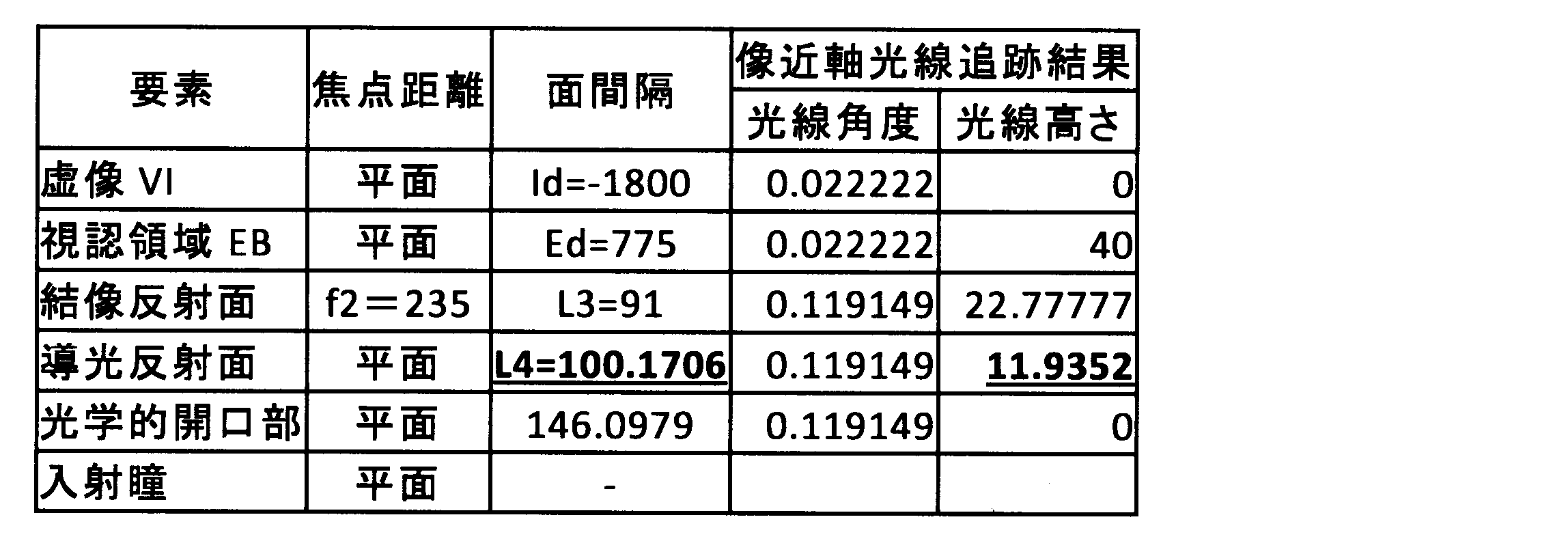
また、表1,2の「間隔」の列では、同じ行の要素と当該要素の1行下の要素との間隔が示されており、表1,2の「光線角度」の列では、同じ行の要素と当該要素の1行下の要素との間における像近軸光線IMRの角度が示されている。表1,2の「光線高さ」の列では、同じ行の要素における像近軸光線IMRの高さが示されている。
In addition, the “interval” column in Tables 1 and 2 indicates the interval between the element in the same row and the element one row below the element, and the “ray angle” column in Tables 1 and 2 indicates the same. The angle of the image paraxial ray IMR between a row element and the element one row below that element is shown. In the column of “ray height” in Tables 1 and 2, the height of the image paraxial ray IMR in the element in the same row is shown.
表1に示される設計結果と表2に示される設計結果とを比較すると、比較例における導光反射面932における「光線高さ」は11.9352mmであるのに対し、本実施形態における導光反射面32の「光線高さ」は8.26894mmである。すなわち、比較例に対して本実施形態では、虚像VIの結像に寄与する光束状の表示光の拡がりが小さくなっている。したがって、導光反射面32のサイズを小さくすることが可能となる。
Comparing the design results shown in Table 1 with the design results shown in Table 2, the “light height” on the light guide reflection surface 932 in the comparative example is 11.9352 mm, whereas the light guide in the present embodiment. The “light height” of the reflecting surface 32 is 8.26894 mm. In other words, in the present embodiment, the spread of luminous flux-shaped display light that contributes to the formation of the virtual image VI is reduced compared to the comparative example. Therefore, the size of the light guide reflection surface 32 can be reduced.
また、結像反射面42の「焦点距離」は、比較例では235mmであるのに対し、本実施形態では166mmである。一方、表1,2に示されていないが、虚像倍率は、比較例では5.361702であるのに対し、本実施形態では3.526636である。したがって、本実施形態では、結像反射面42の焦点距離が比較例よりも短く設定されているにも関わらず、虚像倍率が比較例よりも小さくなっているので、虚像VIの解像度を高めることに成功している。
Further, the “focal length” of the imaging reflecting surface 42 is 235 mm in the comparative example, whereas it is 166 mm in the present embodiment. On the other hand, although not shown in Tables 1 and 2, the virtual image magnification is 5.361702 in the comparative example, and 3.526636 in the present embodiment. Accordingly, in the present embodiment, the virtual image magnification is smaller than that of the comparative example even though the focal length of the imaging reflecting surface 42 is set shorter than that of the comparative example, so that the resolution of the virtual image VI is increased. Has succeeded.
なお、図5,6は、光学系を模式的に示すものであって、各要素20,32,932,42の形状、寸法関係、各光線PRR,IMR,PURの方向、反射の角度、入射瞳の位置ENPの位置等は、必ずしも正確ではない。また、図5では、瞳距離Pdを図示するため、便宜的に、光学的開口部20からの主光線PRRの延長線上に入射瞳の位置ENPを示している。
5 and 6 schematically show the optical system, and the shape and dimensional relationship of each element 20, 32, 932, 42, the direction of each light ray PRR, IMR, PUR, the angle of reflection, and the incidence. The position of the pupil position ENP or the like is not necessarily accurate. Further, in FIG. 5, in order to illustrate the pupil distance Pd, the position ENP of the entrance pupil is shown on the extension line of the principal ray PRR from the optical aperture 20 for convenience.
(作用効果)
以上説明した本実施形態の作用効果を以下に説明する。 (Function and effect)
The operational effects of the present embodiment described above will be described below.
以上説明した本実施形態の作用効果を以下に説明する。 (Function and effect)
The operational effects of the present embodiment described above will be described below.
本実施形態によると、投射器10から投射された表示光は、凸面状の導光反射面32に反射され、凹面状の結像反射面42へと向かう。故に、投射器10を導光ミラー30に近接させなくても、導光反射面32から結像反射面42へと向かう表示光の光束の拡がり角を大きく設定可能となる。すなわち、結像反射面42に入射するまでの表示光の光束をコンパクトにまとめることができる。こうして、導光反射面32のサイズを小さくしても、確実に導光ミラー30が表示光を導光可能となる。導光ミラー30の体格を抑制できるので、当該導光ミラー30の配置の自由度が高まる。
According to the present embodiment, the display light projected from the projector 10 is reflected by the convex light guide reflection surface 32 and travels toward the concave imaging reflection surface 42. Therefore, even if the projector 10 is not brought close to the light guide mirror 30, the spread angle of the light beam of the display light traveling from the light guide reflection surface 32 to the imaging reflection surface 42 can be set large. That is, the luminous flux of the display light until it enters the imaging reflecting surface 42 can be collected in a compact manner. Thus, even if the size of the light guide reflection surface 32 is reduced, the light guide mirror 30 can reliably guide the display light. Since the physique of the light guide mirror 30 can be suppressed, the freedom degree of arrangement | positioning of the said light guide mirror 30 increases.
したがって、インストルメントパネル2に搭載されたHUD装置100において、導光ミラー30の導光反射面32から、上面部2aより上方に配置された結像反射面42に、表示光が導光される構成であっても、導光ミラー30の体格抑制によって結像反射面42における表示光の反射角増大を抑制可能な導光ミラー30の配置を実現できる。反射角増大の抑制により、例えば上下非対称に発生する虚像VIの歪みを低減できる。以上により、虚像VIの視認性が高いHUD装置100を提供することができる。
Therefore, in the HUD device 100 mounted on the instrument panel 2, display light is guided from the light guide reflection surface 32 of the light guide mirror 30 to the imaging reflection surface 42 disposed above the upper surface portion 2a. Even if it is a structure, arrangement | positioning of the light guide mirror 30 which can suppress the reflection angle increase of the display light in the image formation reflective surface 42 by suppression of the physique of the light guide mirror 30 is realizable. By suppressing the increase in the reflection angle, it is possible to reduce, for example, distortion of the virtual image VI that occurs asymmetrically in the vertical direction. As described above, the HUD device 100 with high visibility of the virtual image VI can be provided.
本実施形態によると、結像反射面42と導光反射面32との合成焦点距離は、正である。したがって、凸面状の導光反射面32と凹面状の結像反射面42との組み合わせにより、像面湾曲を抑制しつつ、虚像VIの拡大を実現することができる。
According to the present embodiment, the combined focal length of the imaging reflection surface 42 and the light guide reflection surface 32 is positive. Therefore, the combination of the convex light guide reflection surface 32 and the concave image formation reflection surface 42 can realize enlargement of the virtual image VI while suppressing curvature of field.
本実施形態によると、凸面状の導光反射面32を有する導光ミラー30が体格を抑制可能な状態で、上面部2aよりも下方に配置されることで、結像反射面42における表示光の反射角増大を抑制しつつも、車両1の乗員が導光ミラー30の存在を認識し難くなるため、車両1の見栄えを高めることができる。
According to the present embodiment, the light guide mirror 30 having the convex light guide reflection surface 32 is disposed below the upper surface portion 2a in a state where the physique can be suppressed, so that the display light on the imaging reflection surface 42 is displayed. While the increase in the reflection angle is suppressed, it becomes difficult for the passenger of the vehicle 1 to recognize the presence of the light guide mirror 30, so that the appearance of the vehicle 1 can be enhanced.
本実施形態によると、数2に示される条件が成立するので、投射器10を導光反射面32と結像反射面42との間の光路上から外れた箇所に配置することができる。
According to the present embodiment, since the condition shown in Equation 2 is satisfied, the projector 10 can be disposed at a location off the optical path between the light guide reflection surface 32 and the imaging reflection surface 42.
本実施形態によると、数4に示される条件が成立するので、HUD装置100の光学系における入射瞳の位置ENPを投射器10よりも導光反射面32側に配置させることができる。したがって、虚像VIの視認に有効な光線を導光反射面32の狭い範囲に集めることができるので、導光ミラー30の体格抑制効果を高めることができる。
According to the present embodiment, since the condition shown in Formula 4 is satisfied, the position ENP of the entrance pupil in the optical system of the HUD device 100 can be arranged closer to the light guide reflection surface 32 than the projector 10. Therefore, since light rays effective for visual recognition of the virtual image VI can be collected in a narrow range of the light guide reflection surface 32, the physique suppression effect of the light guide mirror 30 can be enhanced.
(参考例)
数2に示される条件及び数4に示される条件を成立させつつ、表1の設計に対して、導光反射面32を凹面状に置き換えた導光反射面832が採用された参考例のHUD装置800(図7を参照)の設計結果を、以下の表3に詳細に示す。 (Reference example)
The HUD of the reference example in which the light guide reflection surface 832 in which the lightguide reflection surface 32 is replaced with a concave shape is adopted for the design of Table 1 while the conditions shown in Equation 2 and Equation 4 are satisfied. The design results of the device 800 (see FIG. 7) are detailed in Table 3 below.
数2に示される条件及び数4に示される条件を成立させつつ、表1の設計に対して、導光反射面32を凹面状に置き換えた導光反射面832が採用された参考例のHUD装置800(図7を参照)の設計結果を、以下の表3に詳細に示す。 (Reference example)
The HUD of the reference example in which the light guide reflection surface 832 in which the light

こうした導光反射面832では、製造誤差による焦点距離のばらつきが大きいため、虚像VIの質が安定しなくなる。したがって、表1のように、凸面状の導光反射面32を採用することがより好適である。
In such a light guide reflection surface 832, the variation in focal length due to manufacturing errors is large, so the quality of the virtual image VI becomes unstable. Therefore, as shown in Table 1, it is more preferable to employ a convex light guide reflection surface 32.
なお、図7は、光学系を模式的に示すものであって、各要素20,832,42の形状、寸法関係、光線の方向、反射の角度、入射瞳の位置ENP等は、必ずしも正確ではない。
FIG. 7 schematically shows the optical system, and the shape, dimensional relationship, ray direction, reflection angle, entrance pupil position ENP, etc. of each element 20, 832, 42 are not necessarily accurate. Absent.
(他の実施形態)
本開示は、当該実施形態に限定して解釈されるものではなく、本開示の要旨を逸脱しない範囲内において種々の実施形態に適用することができる。 (Other embodiments)
The present disclosure is not construed as being limited to the embodiment, and can be applied to various embodiments without departing from the gist of the present disclosure.
本開示は、当該実施形態に限定して解釈されるものではなく、本開示の要旨を逸脱しない範囲内において種々の実施形態に適用することができる。 (Other embodiments)
The present disclosure is not construed as being limited to the embodiment, and can be applied to various embodiments without departing from the gist of the present disclosure.
具体的に変形例1としては、導光ミラー30は、全体が上面部2aよりも下方に配置されていなくてもよい。例えば、導光ミラー30の一部が上面部2aから上方へはみ出して配置されていてもよい。
Specifically, as a first modification, the entire light guide mirror 30 may not be disposed below the upper surface portion 2a. For example, a part of the light guide mirror 30 may be disposed so as to protrude upward from the upper surface portion 2a.
変形例2としては、結像反射面42を有するコンバイナ40は、着色等により、半透光性を有するものであってもよく、透光性を有しないものであってもよい。
As a second modification, the combiner 40 having the imaging reflecting surface 42 may be semi-translucent or may not be translucent due to coloring or the like.
変形例3としては、結像反射面42を有するコンバイナ40は、HUD装置100とは別体に設けられていてもよい。
As a third modification, the combiner 40 having the imaging reflection surface 42 may be provided separately from the HUD device 100.
変形例4としては、光学的開口部20は、主光線PRRに対して法線方向を傾斜させた状態で配置されていてもよい。
As a fourth modification, the optical aperture 20 may be disposed in a state in which the normal direction is inclined with respect to the principal ray PRR.
上述のヘッドアップディスプレイ装置は、車両1のインストルメントパネル2に搭載され、インストルメントパネルの上面部2aよりも上方に配置された凹面状の結像反射面42を有するコンバイナ40に、結像反射面にて反射される表示光を投射することにより、乗員に視認可能な虚像VIを表示する。ヘッドアップディスプレイ装置は、表示光を光束状に投射する投射器10と、 投射器からの表示光を結像反射面に向けて反射する導光反射面32を有する導光ミラー30と、を備える。導光反射面は、凸面状である。
The above-described head-up display device is mounted on the instrument panel 2 of the vehicle 1, and forms an image reflection on a combiner 40 having a concave image formation reflection surface 42 disposed above the upper surface portion 2 a of the instrument panel. By projecting display light reflected on the surface, a virtual image VI that is visible to the passenger is displayed. The head-up display device includes a projector 10 that projects display light in the form of a light beam, and a light guide mirror 30 having a light guide reflection surface 32 that reflects display light from the projector toward an imaging reflection surface. . The light guide reflection surface is convex.
このような開示によると、投射器から投射された表示光は、凸面状の導光反射面に反射され、凹面状の結像反射面へと向かう。故に、投射器を導光ミラーに近接させなくても、導光反射面から結像反射面へと向かう表示光の光束の拡がり角を大きく設定可能となる。すなわち、結像反射面に入射するまでの表示光の光束をコンパクトにまとめることができる。こうして、導光反射面のサイズを小さくしても、確実に導光ミラーが表示光を導光可能となる。導光ミラーの体格を抑制できるので、当該導光ミラーの配置の自由度が高まる。
According to this disclosure, the display light projected from the projector is reflected by the convex light guide reflection surface and travels toward the concave imaging reflection surface. Therefore, the divergence angle of the display light beam directed from the light guide reflection surface to the imaging reflection surface can be set large without bringing the projector close to the light guide mirror. That is, the luminous flux of the display light before entering the imaging reflection surface can be gathered in a compact manner. Thus, even if the size of the light guide reflection surface is reduced, the light guide mirror can reliably guide the display light. Since the physique of a light guide mirror can be suppressed, the freedom degree of arrangement | positioning of the said light guide mirror increases.
したがって、インストルメントパネルに搭載されたHUD装置において、導光ミラーの導光反射面から、上面部より上方に配置された結像反射面に、表示光が導光される構成であっても、導光ミラーの体格抑制によって結像反射面における表示光の反射角増大を抑制可能な導光ミラーの配置を実現できる。反射角増大の抑制により、例えば上下非対称に発生する虚像の歪みを低減できる。以上により、虚像の視認性が高いHUD装置を提供することができる。
Therefore, in the HUD device mounted on the instrument panel, even if the display light is guided from the light guide reflection surface of the light guide mirror to the imaging reflection surface disposed above the upper surface portion, The arrangement of the light guide mirror that can suppress the increase in the reflection angle of the display light on the imaging reflecting surface can be realized by suppressing the size of the light guide mirror. By suppressing the increase in the reflection angle, it is possible to reduce, for example, distortion of the virtual image that occurs asymmetrically in the vertical direction. As described above, a HUD device with high visibility of a virtual image can be provided.
本開示は、実施例に準拠して記述されたが、本開示は当該実施例や構造に限定されるものではないと理解される。本開示は、様々な変形例や均等範囲内の変形をも包含する。加えて、様々な組み合わせや形態、さらには、それらに一要素のみ、それ以上、あるいはそれ以下、を含む他の組み合わせや形態をも、本開示の範疇や思想範囲に入るものである。
Although the present disclosure has been described based on the embodiments, it is understood that the present disclosure is not limited to the embodiments and structures. The present disclosure includes various modifications and modifications within the equivalent range. In addition, various combinations and forms, as well as other combinations and forms including only one element, more or less, are within the scope and spirit of the present disclosure.
Claims (5)
- 車両(1)のインストルメントパネル(2)に搭載され、前記インストルメントパネルの上面部(2a)よりも上方に配置された凹面状の結像反射面(42)を有するコンバイナ(40)に、前記結像反射面(42)にて反射される表示光を投射することにより、乗員に視認可能な虚像(VI)を表示するヘッドアップディスプレイ装置であって、
前記表示光を光束状に投射する投射器(10)と、
前記投射器(10)からの前記表示光を前記結像反射面(42)に向けて反射する導光反射面(32)を有する導光ミラー(30)と、を備え、
前記導光反射面(32)は、凸面状であるヘッドアップディスプレイ装置。 A combiner (40) mounted on the instrument panel (2) of the vehicle (1) and having a concave imaging reflection surface (42) disposed above the upper surface portion (2a) of the instrument panel, A head-up display device that displays a virtual image (VI) that is visible to an occupant by projecting display light reflected by the imaging reflection surface (42),
A projector (10) for projecting the display light into a luminous flux;
A light guide mirror (30) having a light guide reflection surface (32) for reflecting the display light from the projector (10) toward the imaging reflection surface (42),
The light guide reflection surface (32) is a head-up display device having a convex shape. - 前記結像反射面(42)と前記導光反射面(32)との合成焦点距離は、正である請求項1に記載のヘッドアップディスプレイ装置。 The head-up display device according to claim 1, wherein a combined focal length of the imaging reflection surface (42) and the light guide reflection surface (32) is positive.
- 前記導光ミラー(30)は、前記上面部(2a)よりも下方に配置されている請求項1又は2に記載のヘッドアップディスプレイ装置。 The head-up display device according to claim 1 or 2, wherein the light guide mirror (30) is disposed below the upper surface portion (2a).
- 前記投射器(10)は、
光を発する光源部(12)と、
光学的に開口することにより、前記光源部(12)が発した光を通過させて画像を形成し、前記画像を前記表示光として投射する光学的開口部(20)と、を有し、
前記導光反射面(32)の光学パワーをφ1と、前記結像反射面(42)の光学パワーをφ2と、それぞれ定義し、
前記結像反射面(42)と前記導光反射面(32)との間隔をL3と定義し、
前記光源部(12)と光学的に共役となる共役点(CP)と、前記共役点から視認される前記虚像との間隔を、0より小さい値としてIdと定義し、
前記共役点における前記表示光の光束半径をEsと定義し、
-Es/IdをAとおき、Es+Ed・(Es/Id)をBとおくと、

A light source unit (12) that emits light;
An optical opening (20) that passes through the light emitted from the light source (12) to form an image and projects the image as the display light.
The optical power of the light guide reflection surface (32) is defined as φ1, and the optical power of the imaging reflection surface (42) is defined as φ2,
An interval between the imaging reflection surface (42) and the light guide reflection surface (32) is defined as L3,
An interval between a conjugate point (CP) optically conjugate with the light source unit (12) and the virtual image viewed from the conjugate point is defined as Id as a value smaller than 0,
The luminous flux radius of the display light at the conjugate point is defined as Es,
If -Es / Id is set to A and Es + Ed · (Es / Id) is set to B,
- 前記導光反射面(32)と前記光学的開口部との間隔をL4と定義し、
前記虚像の半画角をθと定義し、
θをCとおき、-Ed・θをDとおくと、

Define the half angle of view of the virtual image as θ,
If θ is C and −Ed · θ is D,
Priority Applications (4)
| Application Number | Priority Date | Filing Date | Title |
|---|---|---|---|
| US16/095,419 US10732419B2 (en) | 2016-04-26 | 2017-02-28 | Head-up display |
| DE112017002186.3T DE112017002186B4 (en) | 2016-04-26 | 2017-02-28 | HEAD-UP DISPLAY DEVICE |
| CN201780024676.6A CN109073892A (en) | 2016-04-26 | 2017-02-28 | Head-up display |
| KR1020187030570A KR102051359B1 (en) | 2016-04-26 | 2017-02-28 | Head-up display device |
Applications Claiming Priority (2)
| Application Number | Priority Date | Filing Date | Title |
|---|---|---|---|
| JP2016-088313 | 2016-04-26 | ||
| JP2016088313A JP6451686B2 (en) | 2016-04-26 | 2016-04-26 | Head-up display device |
Publications (1)
| Publication Number | Publication Date |
|---|---|
| WO2017187758A1 true WO2017187758A1 (en) | 2017-11-02 |
Family
ID=60161404
Family Applications (1)
| Application Number | Title | Priority Date | Filing Date |
|---|---|---|---|
| PCT/JP2017/007588 WO2017187758A1 (en) | 2016-04-26 | 2017-02-28 | Head-up display device |
Country Status (6)
| Country | Link |
|---|---|
| US (1) | US10732419B2 (en) |
| JP (1) | JP6451686B2 (en) |
| KR (1) | KR102051359B1 (en) |
| CN (1) | CN109073892A (en) |
| DE (1) | DE112017002186B4 (en) |
| WO (1) | WO2017187758A1 (en) |
Families Citing this family (8)
| Publication number | Priority date | Publication date | Assignee | Title |
|---|---|---|---|---|
| JP6319354B2 (en) * | 2016-02-23 | 2018-05-09 | 株式会社デンソー | Head-up display device |
| FR3060138B1 (en) * | 2016-12-08 | 2019-07-05 | Alstom Transport Technologies | RAILWAY VEHICLE COMPRISING A HIGH HEAD DISPLAY |
| JP6644265B2 (en) * | 2017-06-30 | 2020-02-12 | 株式会社Jvcケンウッド | Virtual image display |
| JP6593465B2 (en) * | 2018-01-12 | 2019-10-23 | 株式会社Jvcケンウッド | Virtual image display device |
| JP7119862B2 (en) * | 2018-10-01 | 2022-08-17 | 株式会社デンソー | virtual image display |
| JP7246026B2 (en) * | 2019-07-26 | 2023-03-27 | パナソニックIpマネジメント株式会社 | head up display |
| JP7146862B2 (en) * | 2020-08-13 | 2022-10-04 | 矢崎総業株式会社 | vehicle display |
| CN113687503A (en) * | 2021-09-03 | 2021-11-23 | 上海睿视健康科技有限公司 | Video playing device |
Citations (6)
| Publication number | Priority date | Publication date | Assignee | Title |
|---|---|---|---|---|
| JPS4887534A (en) * | 1972-01-28 | 1973-11-17 | ||
| JPH0667154U (en) * | 1993-03-03 | 1994-09-20 | 日野自動車工業株式会社 | Head-up display device for vehicle |
| JPH10115797A (en) * | 1996-10-09 | 1998-05-06 | Shimadzu Corp | Head-up display |
| US20100271698A1 (en) * | 2009-04-24 | 2010-10-28 | David Kessler | Pupil-expanded volumetric display |
| JP2011128500A (en) * | 2009-12-21 | 2011-06-30 | Nippon Sheet Glass Co Ltd | Lens optical system, image display device and head-up display |
| JP2014191143A (en) * | 2013-03-27 | 2014-10-06 | Nippon Seiki Co Ltd | Head-up display device |
Family Cites Families (16)
| Publication number | Priority date | Publication date | Assignee | Title |
|---|---|---|---|---|
| CN2546903Y (en) * | 2002-02-06 | 2003-04-23 | 滕冠军 | Space three-dimensional image demonstration apparatus |
| JP5126051B2 (en) * | 2008-12-25 | 2013-01-23 | 株式会社デンソー | Lighting device |
| JP5392613B2 (en) * | 2009-09-28 | 2014-01-22 | スタンレー電気株式会社 | Head-up display |
| JP4847627B1 (en) * | 2010-09-21 | 2011-12-28 | パイオニア株式会社 | Display device |
| JP5344069B2 (en) * | 2011-08-29 | 2013-11-20 | 株式会社デンソー | Head-up display device |
| CN103048786B (en) * | 2011-10-17 | 2015-07-01 | 财团法人车辆研究测试中心 | Multi-light-path head-up development device |
| US9076368B2 (en) * | 2012-02-06 | 2015-07-07 | Battelle Memorial Institute | Image generation systems and image generation methods |
| JP5831434B2 (en) | 2012-12-07 | 2015-12-09 | 株式会社デンソー | Head-up display device |
| JP6107380B2 (en) | 2013-04-25 | 2017-04-05 | 日本精機株式会社 | Head-up display device |
| JP6131766B2 (en) * | 2013-08-06 | 2017-05-24 | 株式会社デンソー | Head-up display device for vehicle |
| EP3035105B1 (en) * | 2013-12-27 | 2018-06-06 | Panasonic Intellectual Property Management Co., Ltd. | Display apparatus and display unit |
| KR101572132B1 (en) * | 2014-03-10 | 2015-12-07 | (주)그린광학 | Optical System for Focus Adjustable Head Up Display |
| JP6369148B2 (en) * | 2014-06-09 | 2018-08-08 | 株式会社デンソー | Head-up display device and lighting unit thereof |
| TW201606350A (en) * | 2014-08-12 | 2016-02-16 | Automotive Res & Testing Ct | Head-up display device |
| JP6384867B2 (en) | 2014-11-05 | 2018-09-05 | 三菱重工エンジニアリング株式会社 | Railway compressor equipment, railway vehicles |
| JP5866644B1 (en) * | 2014-12-26 | 2016-02-17 | パナソニックIpマネジメント株式会社 | Head-up display and moving body with head-up display |
-
2016
- 2016-04-26 JP JP2016088313A patent/JP6451686B2/en active Active
-
2017
- 2017-02-28 US US16/095,419 patent/US10732419B2/en active Active
- 2017-02-28 KR KR1020187030570A patent/KR102051359B1/en active IP Right Grant
- 2017-02-28 DE DE112017002186.3T patent/DE112017002186B4/en active Active
- 2017-02-28 CN CN201780024676.6A patent/CN109073892A/en active Pending
- 2017-02-28 WO PCT/JP2017/007588 patent/WO2017187758A1/en active Application Filing
Patent Citations (6)
| Publication number | Priority date | Publication date | Assignee | Title |
|---|---|---|---|---|
| JPS4887534A (en) * | 1972-01-28 | 1973-11-17 | ||
| JPH0667154U (en) * | 1993-03-03 | 1994-09-20 | 日野自動車工業株式会社 | Head-up display device for vehicle |
| JPH10115797A (en) * | 1996-10-09 | 1998-05-06 | Shimadzu Corp | Head-up display |
| US20100271698A1 (en) * | 2009-04-24 | 2010-10-28 | David Kessler | Pupil-expanded volumetric display |
| JP2011128500A (en) * | 2009-12-21 | 2011-06-30 | Nippon Sheet Glass Co Ltd | Lens optical system, image display device and head-up display |
| JP2014191143A (en) * | 2013-03-27 | 2014-10-06 | Nippon Seiki Co Ltd | Head-up display device |
Also Published As
| Publication number | Publication date |
|---|---|
| KR20180122020A (en) | 2018-11-09 |
| US10732419B2 (en) | 2020-08-04 |
| CN109073892A (en) | 2018-12-21 |
| DE112017002186B4 (en) | 2023-03-02 |
| DE112017002186T5 (en) | 2019-01-03 |
| JP2017198800A (en) | 2017-11-02 |
| KR102051359B1 (en) | 2019-12-03 |
| US20190137767A1 (en) | 2019-05-09 |
| JP6451686B2 (en) | 2019-01-16 |
Similar Documents
| Publication | Publication Date | Title |
|---|---|---|
| JP6451686B2 (en) | Head-up display device | |
| KR102208724B1 (en) | Head-up display device | |
| JP5930231B2 (en) | Projection device and head-up display device | |
| JP6579212B2 (en) | Head-up display device | |
| JP6589890B2 (en) | Head-up display device | |
| WO2016208379A1 (en) | Screen device and head-up display device | |
| US20170115553A1 (en) | Scanning projector transmissive screen, and scanning projector system | |
| JP6427095B2 (en) | Display light projection optical system | |
| WO2017141491A1 (en) | Head-up display device | |
| JP6481649B2 (en) | Head-up display device | |
| KR102192933B1 (en) | Virtual image display device, intermediate image forming unit, and image display light generating unit | |
| JP6414131B2 (en) | Projection device and head-up display device | |
| JP6809441B2 (en) | Virtual image display device | |
| WO2019087615A1 (en) | Virtual image display device | |
| JPH04128816A (en) | Head-up display device | |
| WO2018150736A1 (en) | Head-up display device | |
| JPH04172418A (en) | Head-up display device | |
| JP6620706B2 (en) | Head-up display device | |
| WO2017145558A1 (en) | Head-up display device | |
| CN115210629B (en) | virtual image display device | |
| JP7342790B2 (en) | virtual image display device |
Legal Events
| Date | Code | Title | Description |
|---|---|---|---|
| ENP | Entry into the national phase |
Ref document number: 20187030570 Country of ref document: KR Kind code of ref document: A |
|
| 121 | Ep: the epo has been informed by wipo that ep was designated in this application |
Ref document number: 17789047 Country of ref document: EP Kind code of ref document: A1 |
|
| 122 | Ep: pct application non-entry in european phase |
Ref document number: 17789047 Country of ref document: EP Kind code of ref document: A1 |