WO2019087615A1 - Virtual image display device - Google Patents
Virtual image display device Download PDFInfo
- Publication number
- WO2019087615A1 WO2019087615A1 PCT/JP2018/035137 JP2018035137W WO2019087615A1 WO 2019087615 A1 WO2019087615 A1 WO 2019087615A1 JP 2018035137 W JP2018035137 W JP 2018035137W WO 2019087615 A1 WO2019087615 A1 WO 2019087615A1
- Authority
- WO
- WIPO (PCT)
- Prior art keywords
- light
- reflection
- display
- incidence
- display light
- Prior art date
Links
- 230000005540 biological transmission Effects 0.000 claims abstract description 146
- 230000003287 optical effect Effects 0.000 claims abstract description 109
- 239000004973 liquid crystal related substance Substances 0.000 claims abstract description 72
- 230000009471 action Effects 0.000 claims abstract description 12
- 239000010408 film Substances 0.000 claims description 72
- 230000000903 blocking effect Effects 0.000 claims description 25
- 239000000758 substrate Substances 0.000 claims description 14
- 230000003595 spectral effect Effects 0.000 claims description 9
- 239000012788 optical film Substances 0.000 claims description 8
- 238000010030 laminating Methods 0.000 claims description 4
- 230000004048 modification Effects 0.000 description 34
- 238000012986 modification Methods 0.000 description 34
- 230000004907 flux Effects 0.000 description 10
- 238000002834 transmittance Methods 0.000 description 10
- 229910052751 metal Inorganic materials 0.000 description 7
- 239000002184 metal Substances 0.000 description 7
- 229920003002 synthetic resin Polymers 0.000 description 7
- 239000000057 synthetic resin Substances 0.000 description 7
- 239000011521 glass Substances 0.000 description 6
- 229910052782 aluminium Inorganic materials 0.000 description 5
- XAGFODPZIPBFFR-UHFFFAOYSA-N aluminium Chemical compound [Al] XAGFODPZIPBFFR-UHFFFAOYSA-N 0.000 description 5
- 239000003086 colorant Substances 0.000 description 4
- 238000000151 deposition Methods 0.000 description 4
- 238000010521 absorption reaction Methods 0.000 description 3
- 230000006866 deterioration Effects 0.000 description 3
- 230000000694 effects Effects 0.000 description 3
- 239000000463 material Substances 0.000 description 3
- 230000010287 polarization Effects 0.000 description 3
- 238000001228 spectrum Methods 0.000 description 3
- VYPSYNLAJGMNEJ-UHFFFAOYSA-N Silicium dioxide Chemical compound O=[Si]=O VYPSYNLAJGMNEJ-UHFFFAOYSA-N 0.000 description 2
- GWEVSGVZZGPLCZ-UHFFFAOYSA-N Titan oxide Chemical compound O=[Ti]=O GWEVSGVZZGPLCZ-UHFFFAOYSA-N 0.000 description 2
- 239000000428 dust Substances 0.000 description 2
- 239000003889 eye drop Substances 0.000 description 2
- 229940012356 eye drops Drugs 0.000 description 2
- 239000004814 polyurethane Substances 0.000 description 2
- 229920002635 polyurethane Polymers 0.000 description 2
- 229910052814 silicon oxide Inorganic materials 0.000 description 2
- 238000004528 spin coating Methods 0.000 description 2
- 230000000007 visual effect Effects 0.000 description 2
- OAICVXFJPJFONN-UHFFFAOYSA-N Phosphorus Chemical compound [P] OAICVXFJPJFONN-UHFFFAOYSA-N 0.000 description 1
- 229910004298 SiO 2 Inorganic materials 0.000 description 1
- 230000002238 attenuated effect Effects 0.000 description 1
- WUKWITHWXAAZEY-UHFFFAOYSA-L calcium difluoride Chemical compound [F-].[F-].[Ca+2] WUKWITHWXAAZEY-UHFFFAOYSA-L 0.000 description 1
- 230000008859 change Effects 0.000 description 1
- 239000011248 coating agent Substances 0.000 description 1
- 238000000576 coating method Methods 0.000 description 1
- 238000010586 diagram Methods 0.000 description 1
- 239000000446 fuel Substances 0.000 description 1
- ORUIBWPALBXDOA-UHFFFAOYSA-L magnesium fluoride Chemical compound [F-].[F-].[Mg+2] ORUIBWPALBXDOA-UHFFFAOYSA-L 0.000 description 1
- 239000011159 matrix material Substances 0.000 description 1
- 238000001465 metallisation Methods 0.000 description 1
- URLJKFSTXLNXLG-UHFFFAOYSA-N niobium(5+);oxygen(2-) Chemical compound [O-2].[O-2].[O-2].[O-2].[O-2].[Nb+5].[Nb+5] URLJKFSTXLNXLG-UHFFFAOYSA-N 0.000 description 1
- 238000005457 optimization Methods 0.000 description 1
- BPUBBGLMJRNUCC-UHFFFAOYSA-N oxygen(2-);tantalum(5+) Chemical compound [O-2].[O-2].[O-2].[O-2].[O-2].[Ta+5].[Ta+5] BPUBBGLMJRNUCC-UHFFFAOYSA-N 0.000 description 1
- 230000000149 penetrating effect Effects 0.000 description 1
- 229920003217 poly(methylsilsesquioxane) Polymers 0.000 description 1
- 239000010409 thin film Substances 0.000 description 1
- OGIDPMRJRNCKJF-UHFFFAOYSA-N titanium oxide Inorganic materials [Ti]=O OGIDPMRJRNCKJF-UHFFFAOYSA-N 0.000 description 1
- 238000007740 vapor deposition Methods 0.000 description 1
- XLYOFNOQVPJJNP-UHFFFAOYSA-N water Substances O XLYOFNOQVPJJNP-UHFFFAOYSA-N 0.000 description 1
Images


Classifications
-
- B—PERFORMING OPERATIONS; TRANSPORTING
- B60—VEHICLES IN GENERAL
- B60K—ARRANGEMENT OR MOUNTING OF PROPULSION UNITS OR OF TRANSMISSIONS IN VEHICLES; ARRANGEMENT OR MOUNTING OF PLURAL DIVERSE PRIME-MOVERS IN VEHICLES; AUXILIARY DRIVES FOR VEHICLES; INSTRUMENTATION OR DASHBOARDS FOR VEHICLES; ARRANGEMENTS IN CONNECTION WITH COOLING, AIR INTAKE, GAS EXHAUST OR FUEL SUPPLY OF PROPULSION UNITS IN VEHICLES
- B60K35/00—Instruments specially adapted for vehicles; Arrangement of instruments in or on vehicles
- B60K35/20—Output arrangements, i.e. from vehicle to user, associated with vehicle functions or specially adapted therefor
- B60K35/21—Output arrangements, i.e. from vehicle to user, associated with vehicle functions or specially adapted therefor using visual output, e.g. blinking lights or matrix displays
- B60K35/23—Head-up displays [HUD]
- B60K35/235—Head-up displays [HUD] with means for detecting the driver's gaze direction or eye points
-
- G—PHYSICS
- G02—OPTICS
- G02B—OPTICAL ELEMENTS, SYSTEMS OR APPARATUS
- G02B26/00—Optical devices or arrangements for the control of light using movable or deformable optical elements
- G02B26/08—Optical devices or arrangements for the control of light using movable or deformable optical elements for controlling the direction of light
- G02B26/10—Scanning systems
-
- G—PHYSICS
- G02—OPTICS
- G02B—OPTICAL ELEMENTS, SYSTEMS OR APPARATUS
- G02B27/00—Optical systems or apparatus not provided for by any of the groups G02B1/00 - G02B26/00, G02B30/00
- G02B27/01—Head-up displays
Definitions
- the present disclosure relates to a virtual image display device that displays a virtual image in a viewable manner.
- the virtual image display device disclosed in Patent Document 1 includes a concave mirror, an image light emitting unit, and a reflection mirror. At least a part of the concave mirror is provided with a half mirror area consisting of a half mirror.
- the image light emitting unit emits display light of the image toward the half mirror area.
- the reflection mirror forms a reciprocating light path for reciprocating the display light with the concave mirror by reflecting the display light transmitted through the half mirror region toward the reflection mirror.
- the display light reflected by the reflection mirror is reflected toward the projection unit by the concave mirror including the half mirror area.
- the image is projected to the projection unit.
- One object disclosed is to provide a virtual image display device with good visibility of a virtual image.
- the virtual image display device disclosed herein is a virtual image display device that displays a virtual image so that the image can be viewed visually by projecting the image onto the projection unit.
- a reflective / transmissive member having a reflection wavelength region as a wavelength region for reflecting light and a transmission wavelength region as a wavelength region for transmitting light by being provided with an optical multilayer film formed by laminating optical films ,
- An image light emitting unit that emits display light of an image toward the reflective / transmissive member;
- reciprocate reflection member constituting a reciprocation light path for causing display light to reciprocate between it and the reflection / transmission member by reflecting the display light having passed through the reflection / transmission member toward the reflection / transmission member again,
- the first incident angle of the display light from the image light emitting portion side to the optical multilayer film of the reflective / transmissive member is defined as the first incidence, and the display light from the reciprocating reflective member side of the reciprocating light path to the optical multilayer film of the reflective / transmissive member If the incident by the
- the first incident angle of the display light to the reflective / transmissive member is different from the second incident angle. Due to the difference in the incident angle, the reflection wavelength region and the transmission wavelength region realized by the optical multilayer film provided in the reflection and transmission member are shifted. Using such a shift action, the display light is guided to the reciprocating reflection member side of the reciprocating light path at the first incidence, and the display light is guided to the projection unit side at the second incidence.
- the condition that the display light is incident at the second incident angle if the wavelength of the display light falls under one of the reflection wavelength region and the transmission wavelength region.
- the transmission action and the reflection action of the optical multilayer film on the display light are switched by making the incident angles different from each other so that the wavelength of the display light falls under the other of the reflection wavelength region and the transmission wavelength region below.
- FIG. 1 It is a schematic diagram which shows the mounting state to the vehicle of the HUD apparatus of 1st Embodiment. It is a figure which shows schematic structure of the HUD apparatus of 1st Embodiment, Comprising: It is the figure which looked at a HUD apparatus in the direction from the left to the right. It is a figure which shows schematic structure of the HUD apparatus of 1st Embodiment, Comprising: It is the figure which looked at a HUD apparatus from the upper direction to the downward direction. It is a figure which shows schematic structure of the liquid crystal display of 1st Embodiment. It is a graph which shows the spectrum of the display light immediately after inject
- FIG. 2 It is a figure for demonstrating the reflective transmission member of 1st Embodiment. It is a graph which shows the reflectance characteristic of the optical multilayer film of 1st Embodiment. It is a figure corresponding to FIG. 2 in 2nd Embodiment. It is a figure which shows schematic structure of the laser indicator of 2nd Embodiment. It is a figure corresponding to FIG. 2 in 3rd Embodiment. It is a figure corresponding to FIG. 3 in 3rd Embodiment. It is a figure corresponding to FIG. 7 in 3rd Embodiment. It is a figure corresponding to FIG. 2 in 4th Embodiment. It is a figure corresponding to FIG. 2 in 5th Embodiment.
- FIG. 2 It is a figure corresponding to FIG. 2 in 6th Embodiment. It is a figure corresponding to FIG. 2 in 7th Embodiment. It is a figure corresponding to FIG. 9 in 8th Embodiment. It is a figure corresponding to FIG. 7 in 8th Embodiment. It is a figure corresponding to FIG. 2 in 9th Embodiment. It is a figure corresponding to FIG. 7 in 9th Embodiment. It is a figure corresponding to FIG. 2 in the modification 1.
- FIG. It is a figure corresponding to FIG. 3 in the modification 1.
- FIG. It is a figure corresponding to FIG. 2 in the modification 2.
- FIG. It is a figure corresponding to FIG. 3 in the modification 2.
- FIG. 26 is a view corresponding to FIG. 5 in an example of modification 4;
- FIG. 26 is a view corresponding to FIG. 5 in another example of modification 4;
- FIG. 21 is a view corresponding to FIG. 2 in an example of modification 6.
- FIG. 31 is a view corresponding to FIG. 2 in another example of the modification 6.
- FIG. 21 is a view corresponding to FIG. 2 in an example of modification 7;
- FIG. 31 is a view corresponding to FIG. 2 in another example of modification 7; It is a figure corresponding to FIG. 2 in the modification 13.
- FIG. It is a figure corresponding to FIG. 2 in the modification 14.
- FIG. It is a figure corresponding to FIG. 2 in the modification 15.
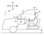
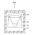
- the virtual image display device is used in a vehicle 1 and is a head-up display device (hereinafter referred to as HUD device) housed in an instrument panel 2 of the vehicle 1. It is 100.
- the HUD device 100 projects an image toward the projection unit 3 a set on the windshield 3 of the vehicle 1.
- the HUD device 100 displays an image as a virtual image so as to be visible by an occupant as a viewer. That is, when the display light of the image reflected by the projection unit 3a reaches the viewing area EB set in the room of the vehicle 1, the occupant whose eye point EP is located in the viewing area EB is a virtual image of the display light Perceive as VRI.
- various information displayed as a virtual image VRI examples include information indicating the state of the vehicle 1 such as the vehicle speed and the remaining amount of fuel, or navigation information such as visibility auxiliary information and road information.
- the windshield 3 of the vehicle 1 is formed of, for example, glass or synthetic resin in a translucent plate shape, and is disposed above the instrument panel 2.
- the windshield 3 forms the projection part 3a on which the display light is projected in a smooth concave or planar shape.
- the projection unit 3 a may not be provided on the windshield 3.
- a combiner that is separate from the vehicle 1 may be installed in the vehicle 1, and the projector 3a may be provided in the combiner.
- the visual recognition area EB is a space area that can be visually recognized so that the virtual image VRI displayed by the HUD device 100 satisfies a predetermined standard, and is also referred to as an eye box.
- the visual recognition area EB is typically set to overlap the eyedrops set in the vehicle 1.
- the eye drops are set in an ellipsoidal shape based on an eye range that statistically represents the spatial distribution of the eye point EP of the occupant.
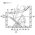
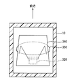
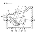
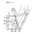
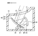
- the HUD device 100 includes a housing 10, a liquid crystal display 20 as an image school unit, a reflection / transmission member 40, a reciprocating reflection member 50, and the like. Since the HUD device 100 can be downsized, it can be easily mounted on the vehicle 1.
- the housing 10 is made of, for example, a synthetic resin or metal, and has a hollow shape that accommodates the other elements of the HUD device 100 such as the liquid crystal display 20 and the reciprocating reflection member 50. is set up.
- the housing 10 has a window 11 which is optically opened on the upper surface facing the projection 3a.
- the window portion 11 is covered with a dustproof sheet 12 capable of transmitting display light.
- the image light emitting unit emits display light of an image formed as a virtual image VRI toward the reflection and transmission member 40.
- the image light emitting unit of the present embodiment is a liquid crystal display 20.
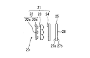
- the liquid crystal display 20 has a back light portion 21 and a liquid crystal panel 26, and is configured by, for example, accommodating them in a box-like casing 20a.
- the backlight unit 21 includes, for example, a light source 22, a condenser lens 23, a field lens 24, and the like.
- the light source 22 is configured, for example, by arranging a plurality of light emitting elements 22 a.
- the light emitting element 22 a in the present embodiment is a light emitting diode element disposed on the light source circuit board 22 b and connected to a power supply.
- Each light emitting element 22 a emits light with a light emission amount corresponding to the amount of current when it is energized.
- pseudo white light emission is realized by covering a blue light emitting diode with a yellow phosphor.
- the condenser lens 23 and the field lens 24 are disposed between the light source 22 and the liquid crystal panel 26.
- the condenser lens 23 is formed of, for example, a synthetic resin or glass so as to be translucent.
- the condenser lens 23 of the present embodiment is a lens array in which a plurality of convex lens elements are arranged in accordance with the number and arrangement of the light emitting elements 22a.
- the condenser lens 23 condenses the light incident from the light source 22 side and emits the light to the field lens 24 side.
- the field lens 24 is disposed between the condenser lens 23 and the liquid crystal panel 26, and is formed of, for example, a synthetic resin or glass to have translucency.
- the field lens 24 further condenses the light incident from the condenser lens 23 side, and emits the light toward the liquid crystal panel 26 side.
- the liquid crystal panel 26 of the present embodiment is a liquid crystal panel using thin film transistors (TFTs), and is, for example, an active matrix liquid crystal panel formed of a plurality of liquid crystal pixels arranged in a two-dimensional direction. .
- TFTs thin film transistors
- a liquid crystal layer or the like sandwiched between a pair of linear polarizing plates 27a and 27b and a pair of linear polarizing plates 27a and 27b is stacked.
- Each of the linear polarization plates 27a and 27b transmits light polarized in a direction along the transmission axis and shields light polarized in a direction along an absorption axis orthogonal to the transmission axis.
- the pair of linear polarization plates 27a and 27b are disposed such that the transmission axes are substantially orthogonal to each other.
- the liquid crystal layer is capable of rotating the polarization direction of light incident on the liquid crystal layer according to the applied voltage by voltage application for each liquid crystal pixel.
- the liquid crystal panel 26 can form an image by display light emitted from the display screen 28 by controlling the transmittance of the light for each liquid crystal pixel when the light from the backlight unit 21 is incident. There is.
- the display light is emitted from the display screen 28 as linearly polarized light along the transmission axis of the linear polarizing plate 27b on the emission side.
- adjacent liquid crystal pixels are provided with color filters of different colors (for example, red, green, and blue), and various colors are realized by a combination of these.
- the color filters of each color have their own wavelength characteristics of transmittance, and the maximum transmittance wavelengths at which the transmittance is maximum are set to be different from each other.
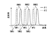
- the display light emitted from the backlight unit 21 through the liquid crystal panel 26 depends on the displayed image, it has a plurality of peak wavelengths WP1, WP2 and WP3 as shown in FIG. 5, for example. It has become a thing.
- the plurality of peak wavelengths WP1, WP2, and WP3 of the display light correspond to the transmission maximum wavelengths of the respective color filters, for example, about 450 nm corresponding to the blue color filter, and about 530 nm corresponding to the green color filter. , And corresponding to about 600 nm corresponding to red color filters.
- the display light of this embodiment has three peak wavelengths WP1, WP2 and WP3 but has a continuous spectrum in most of the visible light region.
- the liquid crystal display 20 of the present embodiment emits display light from the front toward the rear.
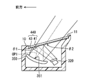
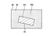
- the reflective / transmissive member 40 has, for example, a flat plate shape in which an optical multilayer film 43 is formed on the entire surface on one side of the light transmitting substrate 41.
- the reflection / transmission member 40 of the present embodiment is disposed obliquely rearward of the liquid crystal display 20 so that the normal direction thereof is forward, downward, backward, and upward.
- the light transmitting substrate 41 is formed of, for example, a synthetic resin or glass in a light transmitting flat plate shape having a high transmittance.
- the optical multilayer film 43 may be formed by, for example, depositing, spin coating, or attaching a film to the surface of the reflective / transmissive member 40 opposite to the liquid crystal display 20 (that is, the surface on the reciprocating reflective member 50 side) It is formed by
- the optical multilayer film 43 is formed by laminating thin-film-like optical films made of optical materials of two or more types different in refractive index along the normal direction of the surface of the reflective / transmissive member 40.
- the optical film for example, titanium oxide (TiO 2), silicon oxide (SiO 2), niobium oxide (Nb 2 O 5), tantalum oxide (Ta 2 O 5), magnesium fluoride (MgF 2), calcium fluoride (CaF 2) or the like may be employed. It is possible.
- the optical multilayer film 43 of the present embodiment is formed by alternately laminating an optical film made of titanium oxide and an optical film made of silicon oxide.
- Each film thickness in each optical film is appropriately set in advance by optimization calculation that simulates light interference by a computer. Therefore, the wavelength characteristics of the reflectance and the wavelength characteristics of the transmittance of the reflective / transmissive member 40 are characterized based on the result of the light interference in the optical multilayer film 43.
- the reflection wavelength regions RWR 1, RWR 2, RWR 3 as light wavelength regions and light are transmitted.
- Transmission wavelength regions TWR1, TWR2 and TWR3 as wavelength regions are alternately provided.
- the reflection wavelength regions RWR1, RWR2, RWR3 and the transmission wavelength regions TWR1, TWR2, TWR3 are respectively configured to have the same number or more as the peak wavelengths WP1, WP2, WP3 of the display light.
- the third reflection wavelength region RWR3 are set alternately.
- another reflection wavelength region or the like may be set on the shorter wavelength side than the first transmission wavelength region TWR1, and the other reflection wavelength region may be set on the longer wavelength side than the third reflection wavelength region RWR3.
- Another transmission wavelength region or the like may be set.
- display light from the liquid crystal display 20 is obliquely incident on the reflective / transmissive member 40.
- the incidence to the optical multilayer film 43 of the reflective transmission member 40 from the liquid crystal display 20 side is defined as the first incidence
- the incidence angle to the optical multilayer film 43 of the display light at the first incidence is the first incidence angle It is defined as ⁇ 1.
- the optical multilayer film 43 is configured such that the peak wavelengths WP1, WP2 and WP3 are included in the transmission wavelength regions TWR1, TWR2 and TWR3 under the condition that the display light is incident at the first incident angle ⁇ 1 as shown in FIG. It is done.
- the peak wavelength WP1 of about 450 nm corresponding to the blue color filter is included in the first transmission wavelength range TWR1
- the peak wavelength WP2 of about 530 nm corresponding to the green color filter is included in the second transmission wavelength range TWR2.
- the reflectance is set to 50% or less, more preferably 20% or less.
- the reflectance to the entire display light is 50% or less, More preferably, it is 20% or less.
- the display light is transmitted through the reflection / transmission member 40 with a transmittance of 50% or more, more preferably 80% or more.
- the reflectance is the energy reflectance
- the transmittance is the energy transmittance.
- the reciprocating reflection member 50 is disposed.
- the reciprocating reflection member 50 has a reflecting mirror in which a metal film such as aluminum is deposited as a reflecting surface 51 on the surface of a base material made of synthetic resin or glass, for example. It has become.
- the reflecting surface 51 is formed in a curved shape, and is curved in a concave shape such that the center of the reciprocating reflecting member 50 is recessed, for example. That is, the reciprocating reflection member 50 is a positive optical element having a positive optical power.
- the reflective surface 51 of the present embodiment is disposed to face the front at the rear of the reflective / transmissive member 40.
- the reciprocating reflection member 50 reflects the display light, which has passed through the reflection / transmission member 40 from the liquid crystal display 20 side, toward the reflection / transmission member 40 again, with high reflectance.
- the reciprocating reflection member 50 constitutes a reciprocating light path OP1 for causing the display light to reciprocate between itself and the reflection / transmission member 40.
- the reciprocating optical path OP1 By constructing the reciprocating optical path OP1, it is possible to arrange the reflective / transmissive member 40 and the reciprocating reflective member 50 so that the incident angle and the reflection angle to the reflective surface 51 become smaller (for example, in the range of 10 to 15 degrees). It becomes.
- the direction of the display light is corrected to be slightly upward in the return path of the reciprocating optical path OP1 than the outward path of the reciprocating optical path OP1.
- the display light is obliquely incident on the reflection / transmission member 40 again.
- the incidence to the optical multilayer film 43 of the reflective transmission member 40 from the side of the reciprocal reflection member 50 of the reciprocating optical path OP1 is defined as the second incidence
- the incident angle of the display light at the second incidence to the optical multilayer film 43 is It is defined as 2 incident angle ⁇ 2.
- the second incident angle ⁇ 2 is different from the first incident angle ⁇ 1, and particularly in the present embodiment, the second incident angle ⁇ 2 is larger than the first incident angle ⁇ 1.
- the difference between the second incident angle ⁇ 2 and the first incident angle ⁇ 1 is about twice of the incident angle on the reflecting surface 51, and is set, for example, in the range of 20 to 30 degrees.
- the optical multilayer film 43 has a characteristic that the reflection wavelength regions RWR1, RWR2, RWR3 and the transmission wavelength regions TWR1, TWR2, TWR3 shift in accordance with the incident angle of light. Specifically, the larger the incident angle of light, the longer the optical path length when the light passes through each optical film in the optical multilayer film 43. Therefore, the reflection wavelength regions RWR1, RWR2, RWR3 and the transmission wavelength regions TWR1, TWR1, RWR2 TWR2 and TWR3 shift to the short wavelength side as a whole.
- the optical multilayer film 43 is such that the peak wavelengths WP1, WP2 and WP3 are individually included in the corresponding reflection wavelength regions RWR1, RWR2 and RWR3 under the condition that the display light is incident at the second incident angle ⁇ 2. It is configured.
- the peak wavelength WP1 of about 450 nm corresponding to the blue color filter is included in the first reflection wavelength range RWR1
- the peak wavelength WP2 of about 530 nm corresponding to the green color filter is in the second reflection wavelength range RWR2.
- a peak wavelength WP3 of about 600 nm, which is included and corresponds to the red color filter, is included in the third reflection wavelength range RWR3.
- the reflectance is set to 50% or more, more preferably to 80% or more.
- the reflectance to the entire display light is also 50% or more, More preferably, it is 80% or more.
- the display light is reflected by the reflective / transmissive member 40 with a reflectance of 50% or more, more preferably 80% or more.
- the display light reflected by the reflective / transmissive member 40 is transmitted through the upper window portion 11 to be emitted to the outside of the housing 10 and projected on the projection portion 3a.
- the occupant can visually recognize the virtual image VRI.
- the virtual image VRI is displayed larger than the display screen 28 of the liquid crystal panel 26 by curving the reflection surface 51 of the reciprocating reflection member 50 in a concave shape.
- the incident angle at the time of reflection is set small in the range of 10 to 20 degrees. It has become possible. Therefore, distortion of the vertically asymmetric (or bilaterally asymmetric) virtual image VRI that may occur together with the magnifying action can be suppressed.
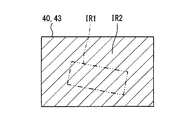
- the region on the reflective / transmissive member 40 where the display light is incident on the reflective / transmissive member 40 is It is defined as a first incident region IR1.
- the region on the reflective / transmissive member 40 where the display light is incident on the reflective / transmissive member 40 is defined as a second incident region IR2. .
- the luminous flux spreads as the display light travels, so the area of the second incident region IR2 becomes wider than the first incident region IR1.
- the first incident region IR1 and the second incident region IR2 are set to partially overlap. Such partial overlapping makes it possible to configure an optical system in which the first incident angle ⁇ 1 and the second incident angle ⁇ 2 are different while reducing the size of the reflective / transmissive member 40.
- the reflective / transmissive member 40 is formed in a flat plate shape, the incident angle to the reflective / transmissive member 40 can be prevented from being largely different between the center and the outside of the light flux of the display light. Therefore, transmission of display light with less unevenness can be realized in the entire first incident region IR1, and reflection of display light with less unevenness can be realized in the entire second incident region IR2. Therefore, it is possible to display a virtual image VRI with less luminance unevenness.
- the first incident angle ⁇ 1 and the second incident angle ⁇ 2 of the display light to the reflection and transmission member 40 are different from each other. Due to the difference between the incident angles ⁇ 1 and ⁇ 2, the reflection wavelength regions RWR1, RWR2 and RWR3 and the transmission wavelength regions TWR1, TWR2 and TWR3 realized by the optical multilayer film 43 provided in the reflection and transmission member 40 are shifted. . Using such a shift action, the display light is guided to the reciprocating reflection member 50 side of the reciprocating light path OP1 at the first incidence, and the display light is guided to the projection unit 3a at the second incidence.
- the incident angle ⁇ 1 is such that the wavelength of the display light corresponds to the other of the reflection wavelength regions RWR1, RWR2, RWR3 and the transmission wavelength regions TWR1, TWR2, TWR3.
- the first incident angle ⁇ 1 is set such that the plurality of peak wavelengths WP1, WP2, and WP3 are individually included in the transmission wavelength regions TWR1, TWR2, and TWR3 at the first incidence.
- the second incident angle so that the display light is transmitted through the reflective / transmissive member 40 and the plurality of peak wavelengths WP1, WP2 and WP3 are individually included in the reflected wavelength regions RWR1, RWR2 and RWR3 at the second incidence.
- the display light is reflected by the reflective / transmissive member 40 by setting ⁇ 2.
- each major wavelength component constituting the display light is projected onto the projection unit 3a while securing the optical path length in the reciprocating optical path OP1 reliably, a virtual image VRI of high luminance is displayed while securing an easy-to-see distance. Can. According to the above, it is possible to provide the HUD device 100 having good visibility of the virtual image VRI.
- the reflectance of display light at the first incidence is 50% or less, and the reflectance of display light at the second incidence is 50% or more.
- Such setting of the reflectance surely enhances the energy efficiency as compared with the case where the reciprocating optical path OP1 is configured using a simple half mirror.
- the image light emitting unit transmits the light from the backlight unit 21 for supplying light and the light from the backlight unit 21, and reflects the reflection wavelength regions RWR 1, RWR 2, RWR 3 and the optical multilayer film 43.
- a liquid crystal panel 26 which emits display light with a spectral distribution matched to the transmission wavelength regions TWR1, TWR2 and TWR3.
- the optical multilayer film 43 is formed on the surface of the light transmitting substrate 41 on the side where the display light is incident at the second incidence. Since the display light is reflected by the optical multilayer film 43 while suppressing the reciprocation of the light transmitting substrate 41 at the second incidence, the generation of a double image due to the reflection of the light transmitting substrate 41 is suppressed. Can. Therefore, the visibility of the virtual image VRI can be further improved.
- the second embodiment is a modification of the first embodiment.
- the second embodiment will be described focusing on differences from the first embodiment.
- the image light emitting unit according to the second embodiment emits display light of an image formed as a virtual image VRI, as in the first embodiment.
- the image light emitting unit of the second embodiment is a laser display 220.
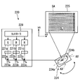
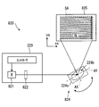
- the laser display 220 has a plurality of laser oscillators 221a, 221b and 221c, a plurality of collimate lenses 222a, 222b and 222c, a folding mirror 223a, a plurality of dichroic mirrors 223b and 223c, and a scanning unit 224, as shown in detail in FIG. , And a screen member 225.
- three laser oscillators 221a, 221b and 221c and three collimating lenses 222a, 222b and 222c are provided.
- the three laser oscillators 221a, 221b, and 221c oscillate laser beams having different peak wavelengths.
- the laser oscillator 221a oscillates a green laser beam having a peak wavelength in the range of 490 to 530 nm, preferably 515 nm, for example.
- the laser oscillator 221b oscillates a blue laser beam having a peak wavelength of, for example, 430 to 470 nm, preferably 450 nm.
- the laser oscillator 221 c is configured to oscillate, for example, a red laser beam having a peak wavelength in the range of 600 to 650 nm, preferably 640 nm.
- the respective laser beams oscillated from the respective laser oscillators 221a, 221b and 221c enter the corresponding collimating lenses 222a, 222b and 222c.
- the three collimating lenses 222a, 222b and 222c are arranged at predetermined intervals in the traveling direction of the respective laser beams with respect to the corresponding laser oscillators 221a, 221b and 221c.
- Each collimating lens 222a, 222b, 222c substantially collimates the laser beam by refracting the laser beam of the corresponding color.
- the folding mirror 223a is disposed at a predetermined distance in the traveling direction of the laser beam with respect to the collimating lens 222a, and reflects the green laser beam transmitted through the collimating lens 222a.
- the two dichroic mirrors 223b and 223c are disposed at predetermined intervals in the traveling direction of the respective laser beams with respect to the corresponding collimating lenses 222b and 222c.
- Each of the dichroic mirrors 223b and 223c reflects a laser beam having a specific wavelength among the laser beams transmitted through the corresponding collimator lenses 222b and 222c, and transmits the other laser beams.
- the dichroic mirror 223b corresponding to the collimator lens 222b reflects the blue laser beam and transmits the green laser beam.
- the dichroic mirror 223c corresponding to the collimator lens 222c reflects the red laser beam and transmits the green and blue laser beams.
- dichroic mirrors 223b are disposed at predetermined intervals in the traveling direction of the green laser light flux reflected by the reflection mirror 223a.
- the dichroic mirror 223c is disposed at a predetermined interval. According to these arrangements, the green laser beam reflected by the reflecting mirror 223a passes through the dichroic mirror 223b and is superimposed on the blue laser beam reflected by the dichroic mirror 223b. Also, the green laser beam and the blue laser beam are transmitted through the dichroic mirror 223c, and are superimposed on the red laser beam reflected by the dichroic mirror 223c.
- Each of the laser oscillators 221 a, 221 b and 221 c is electrically connected to the controller 229.
- Each of the laser oscillators 221 a, 221 b and 221 c oscillates a laser beam according to the electric signal from the controller 229.
- various colors are realized by additively mixing the laser beams of three colors oscillated from the respective laser oscillators 221a, 221b and 221c.
- the laser light flux enters the scanning unit 224 in a state where the laser light fluxes having different peak wavelengths overlap one another.
- the scanning unit 224 has a scanning mirror 224a.
- the scanning mirror 224a is a MEMS mirror configured to be able to temporally scan a laser light flux using a micro electro mechanical system (MEMS).
- MEMS micro electro mechanical system
- a reflective film 224b is provided in the scanning mirror 224a, on the surface facing the dichroic mirror 223c at a predetermined interval, a reflective film 224b is provided by forming a metal film by metal deposition such as aluminum or the like.
- the reflecting surface 224b is rotatable around two rotation axes Ax and Ay substantially orthogonal to the reflecting surface 224b.
- Such a scanning mirror 224a is electrically connected to the controller 229. By rotating in accordance with the scanning signal, the direction of the reflecting surface 224b can be changed.
- the scanning unit 224 controls the scanning mirror 224a by the controller 229 to interlock with the laser oscillators 221a, 221b, and 221c, for example, starting from a deflection point which is an incident place on the reflection surface 224b of the laser beam. It is possible to deflect the projection direction of the laser beam temporally.
- the laser beam scanned by the scanning unit 224 by deflection at the deflection point is incident on the screen member 225.
- the screen member 225 is a reflection type screen formed in a mirror array by depositing aluminum on the surface of a base material made of, for example, a synthetic resin or glass. Although not shown in detail, the screen member 225 has a plurality of optical curved surfaces arranged in a lattice on the surface on the side of the scanning mirror 224 a and the reflective / transmissive member 240.
- An image is drawn in the scan area SA of the screen member 225 by the incidence of the laser beam scanned by the scan unit 224.
- the scanning unit 224 is sequentially scanned along the plurality of scanning lines SL under the control of the controller 229.
- the laser beam is intermittently pulse-irradiated, whereby an image is drawn.
- An image drawn by projection onto the scanning area SA is drawn at 60 frames per second as an image having 480 pixels in the xs direction along the scanning line SL and 240 pixels in the ys direction substantially perpendicular to the scanning line SL, for example.
- the laser beam corresponding to each projection direction is emitted from the screen member 225 while expanding the spread angle by the reflection on each optical curved surface.
- the spot diameter of each laser beam is enlarged by the optical curved surface formed by curving in a convex or concave shape.
- the laser display 220 emits display light having a plurality of peak wavelengths WP1, WP2, and WP3 corresponding to the peak wavelength of each laser light flux toward the reflective / transmissive member 240.
- the optical multilayer film 243 has reflection wavelength regions RWR1, RWR2, RWR3 and transmission wavelength regions TWR1, TWR2, TWR3 in the visible light region, as in the first embodiment. Similar to the first embodiment, the optical multilayer film 243 has a characteristic that the reflection wavelength regions RWR1, RWR2, RWR3 and the transmission wavelength regions TWR1, TWR2, TWR3 shift according to the incident angle of light.
- the optical multilayer film 243 is configured such that the peak wavelengths WP1, WP2, and WP3 are included in the transmission wavelength regions TWR1, TWR2, and TWR3 under the condition that the display light is incident at the first incident angle ⁇ 1.
- the peak wavelength WP1 of about 450 nm corresponding to the blue laser beam is included in the first transmission wavelength region TWR1
- the peak wavelength WP2 of about 515 nm corresponding to the green laser beam is in the second transmission wavelength region TWR2.
- a peak wavelength WP3 of about 640 nm, which is included and corresponds to the red laser beam, is included in the third transmission wavelength range TWR3.
- the spectral half-widths of the peak wavelengths WP1, WP2, and WP3 of the display light are completely included in the corresponding transmission wavelength regions TWR1, TWR2, and TWR3.
- the optical multilayer film 243 is configured such that the peak wavelengths WP1, WP2, and WP3 are included in the reflection wavelength regions RWR1, RWR2, and RWR3 under the condition that the display light is incident at the second incident angle ⁇ 2.
- a peak wavelength WP1 of about 450 nm corresponding to the blue laser beam is included in the first reflection wavelength range RWR1
- a peak wavelength WP2 of about 515 nm corresponding to the green laser beam is included in the second reflection wavelength range RWR2.
- a peak wavelength WP3 of about 640 nm, which is included and corresponds to the red laser beam, is included in the third reflection wavelength range RWR3.
- the spectral half-widths of the peak wavelengths WP1, WP2, and WP3 of the display light are completely included in the corresponding reflection wavelength regions RWR1, RWR2, and RWR3.
- the image light emitting unit emits laser light as display light. Since the laser light has a small spectral half width, when the reflection wavelength regions RWR1, RWR2, RWR3 and the transmission wavelength regions TWR1, TWR2, TWR3 are shifted, the laser light is transmitted in the desired reflection wavelength regions RWR1, RWR2, RWR3 or Since the wavelength regions TWR1, TWR2, and TWR3 can be easily included, attenuation of display light in the reflective / transmissive member 240 can be minimized.
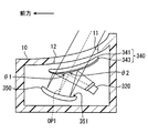
- the third embodiment is a modification of the first embodiment.
- the third embodiment will be described focusing on differences from the first embodiment.
- the liquid crystal display 320 corresponding to the image light emitting unit in the third embodiment has the same internal configuration as that of the first embodiment, but displays light in the forward and upper oblique directions. It emits light.
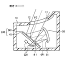
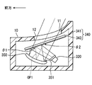
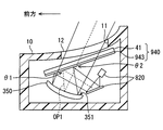
- the reflective / transmissive member 340 of the third embodiment is housed inside the housing 10, and is inclined so that the normal direction is upward, slightly forward, downward, and slightly backward above the liquid crystal display 320. It is arranged.
- the reflective / transmissive member 340 has a flat plate shape in which the optical multilayer film 343 is formed on the entire surface on one side of the light transmitting substrate 341. More specifically, the optical multilayer film 343 is formed, for example, by vapor deposition, spin coating, or affixing a film on the surface of the reflective / transmissive member 340 on the liquid crystal display 320 and the reciprocating reflective member 350 side. There is.
- the optical multilayer film 343 of the third embodiment has a first reflection wavelength region RWR1, a first transmission wavelength region TWR1, a second reflection wavelength region RWR2, and a third reflection wavelength region RWR1 from the short wavelength side.
- the second transmission wavelength region TWR2, the third reflection wavelength region RWR3, and the third transmission wavelength region TWR3 are alternately set.
- another transmission wavelength region or the like may be set on the shorter wavelength side than the first reflection wavelength region RWR1, and the other transmission wavelength region may be set on the longer wavelength side than the third transmission wavelength region TWR3.
- Another reflection wavelength range or the like may be set.
- the optical multilayer film 343 is configured such that the peak wavelengths WP1, WP2, and WP3 are included in the reflection wavelength region RWR1 under the condition that the display light is incident at the first incident angle ⁇ 1.
- the peak wavelength WP1 of about 450 nm corresponding to the blue color filter is included in the first reflection wavelength range RWR1
- the peak wavelength WP2 of about 530 nm corresponding to the green color filter is in the second reflection wavelength range RWR2.
- a peak wavelength WP3 of about 600 nm, which is included and corresponds to the red color filter, is included in the third reflection wavelength range RWR3.
- the reflectance is set to 50% or more, more preferably to 80% or more.
- the reflectance to the entire display light is also 50% or more, More preferably, it is 80% or more.
- the display light is reflected by the reflective / transmissive member 340 with a reflectance of 50% or more, more preferably 80% or more.
- the reciprocal reflection member 350 is disposed ahead of the display light reflected by the reflection / transmission member 340.
- the reflecting surface 351 of the reciprocating reflecting member 350 of the third embodiment is disposed so as to face upward and slightly rearward, below the reflecting / transmitting member 340 and in front of the liquid crystal display 20.
- the reciprocation reflection member 350 constitutes a reciprocation light path OP1 for causing display light to reciprocate between itself and the reflection / transmission member 340.
- the optical multilayer film 343 is configured such that the peak wavelengths WP1, WP2 and WP3 are included in the transmission wavelength regions TWR1, TWR2 and TWR3 under the condition that the display light is incident at the second incident angle ⁇ 2.
- the peak wavelength WP1 of about 450 nm corresponding to the blue color filter is included in the first transmission wavelength range TWR1
- the peak wavelength WP2 of about 530 nm corresponding to the green color filter is included in the second transmission wavelength range TWR2.
- the reflectance is set to 50% or less, more preferably 20% or less.
- the reflectance to the entire display light is 50% or less, More preferably, it is 20% or less.
- the display light is transmitted through the reflection / transmission member 340 at a transmittance of 50% or more, more preferably 80% or more.
- the first incident angle ⁇ 1 is set so that the plurality of peak wavelengths WP1, WP2, and WP3 are individually included in the reflection wavelength regions RWR1, RWR2, and RWR3 at the first incidence.
- the display light is reflected by the reflection / transmission member 340, and the plurality of peak wavelengths WP1, WP2 and WP3 are individually included in the transmission wavelength regions TWR1, TWR2 and TWR3 respectively at the second incidence.
- the incident angle ⁇ 2 is set, and the display light passes through the reflective / transmissive member 340.
- each major wavelength component constituting the display light is projected onto the projection unit 3a while securing the optical path length in the reciprocating optical path OP1 reliably, a virtual image VRI of high luminance is displayed while securing an easy-to-see distance. Can. According to the above, it is possible to provide the HUD device 100 having good visibility of the virtual image VRI.
- the reflectance of display light at the first incidence is 50% or more, and the reflectance of display light at the second incidence is 50% or less.
- Such setting of the reflectance surely enhances the energy efficiency as compared with the case where the reciprocating optical path OP1 is configured using a simple half mirror.
- the optical multilayer film 343 is formed on the surface of the light transmitting substrate 341 on the side where the display light is incident at the first incidence. Since the display light is reflected by the optical multilayer film 343 while suppressing the reciprocation of the light transmission substrate 341 at the first incidence, the generation of a double image due to the reflection at the light transmission substrate 341 is suppressed. Can. Therefore, the visibility of the virtual image VRI can be further improved.
- the fourth embodiment is a modification of the third embodiment.
- the fourth embodiment will be described focusing on differences from the third embodiment.
- the reflective / transmissive member 440 of the fourth embodiment is disposed to close the entire window portion 11 of the housing 10. That is, the reflective / transmissive member 440 is also used as a dustproof sheet that prevents foreign matter (for example, dust, dust, water) from invading the inside of the housing 10 from the outside of the housing 10.
- foreign matter for example, dust, dust, water
- the reflective / transmissive member 440 reflects a part of external light such as sunlight transmitted through the windshield 3 and incident on the window portion 11. The entry of outside light into the interior is also suppressed.
- the reflection / transmission member 440 is also used as a dustproof sheet by closing the window portion 11. Since the component for realizing the optical system in which the reciprocating optical path OP1 is configured and the component for realizing the dustproof sheet are shared, the virtual image can be suppressed while suppressing an increase in the physical size of the HUD device 100 by suppressing the number of components. High visibility of VRI can be realized.
- the fifth embodiment is a modification of the first embodiment.
- the fifth embodiment will be described focusing on differences from the first embodiment.
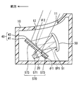
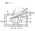
- the HUD device 100 of the fifth embodiment further includes a light blocking unit 570.
- the light blocking portion 570 is formed to have a light absorbing property, for example, of polyurethane colored in dark color such as black, and integrally includes a light blocking hood portion 571 and a light blocking laminated portion 573.
- the light blocking hood portion 571 is formed in a wall shape between the liquid crystal display 20 and the reflective / transmissive member 40 along the traveling direction of the display light and so as not to block the light flux of the display light.
- the light blocking hood portion 571 blocks stray light such as external light by absorption or the like, thereby preventing the stray light from being reflected in the virtual image VRI due to multiple reflection.
- the light blocking laminated portion 573 is disposed by adhering or in close contact with the surface of the reflective / transmissive member 40 on the liquid crystal display 20 side in the region of the reflective / transmissive member 40 excluding the first incident region IR1. , And are arranged in a state of being laminated with the reflective / transmissive member 40.
- the light blocking laminate portion 573 blocks deterioration or damage of the liquid crystal panel 26 or the like of the liquid crystal display 20 by blocking the reflective / transmissive member 40 of the external light by absorption or the like.
- the light blocking laminate portion 573 absorbs the transmitted light. Do.
- the transmitted light is reflected by the surface of the reflection / transmission member 40 on the liquid crystal display 20 side to the projection unit 3 a side and a double image is generated in the virtual image VRI.
- the reflective / transmissive member 40 is disposed to correspond to the region excluding the first incident region IR1 on the liquid crystal display 20 side, and the light blocking / stacked portion 573 in a stacked state with the reflective / transmissive member 40.
- the light intercepts the light that is transmitted through the reflective / transmissive member 40 from the side of the reciprocating reflective member 50 to the side of the liquid crystal display 20.
- Such blocking of light suppresses deterioration or damage of the liquid crystal display 20, so that high visibility of the virtual image VRI can be maintained over a long time.
- the sixth embodiment is a modification of the first embodiment.
- the sixth embodiment will be described focusing on differences from the first embodiment.
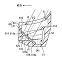
- the housing 610 of the sixth embodiment has a reciprocating reflection member holding wall 613, a reflection / transmission member holding wall 614, and a display hole 615 in its inside.
- the reciprocating reflection member holding wall 613 is formed in a wall shape so as to abut on the opposite side to the reflecting surface 51 in the reciprocating reflection member 50.
- the reciprocating reflection member holding wall 613 holds the reciprocating reflection member 50 by pasting, fitting, fastening, or the like.
- the reflective / transmissive member holding wall 614 is formed in a wall shape so as to abut on a portion of the reflective / transmissive member 40 on the side opposite to the reciprocating reflective member 50 (that is, the liquid crystal display 20 side).
- the reflective / transmissive member holding wall 614 holds the reflective / transmissive member 40 by pasting, fitting, fastening, or the like.
- the reflective / transmissive member holding wall 614 brings the surface 614 a into close contact with the region of the reflective / transmissive member 40 on the liquid crystal display 620 side excluding the first incident region IR1.
- the surface 614 a of the reflective / transmissive member holding wall 614 is formed in, for example, a dark color (for example, black) capable of suppressing the reflection of light.
- the reflective / transmissive member holding wall 614 exerts the blocking effect of the light transmitted through the reflective / transmissive member 40 among the external light and the suppressing effect of the double image as in the light blocking laminated portion 573 of the fifth embodiment.
- the display hole 615 is formed in the shape of a hole opened in the reflective / transmissive member holding wall 614 at a portion corresponding to the first incident region IR1 of the reflective / transmissive member 40.
- the display hole 615 of this embodiment is formed in the shape of a through hole penetrating the housing 610, it may be formed in the shape of a bottomed hole.
- the display hole 615 is a quadrangular frustum shaped hole which is gradually narrowed as it is separated from the reflection / transmission member 40.
- the liquid crystal display 620 corresponding to the image light emitting portion in the sixth embodiment is disposed at a position apart from the reflective / transmissive member 40 in the display hole 615.
- the liquid crystal panel 26 is opposed to the reflective / transmissive member 40, and a part of the backlight unit 21 is disposed outside the housing 10.
- the liquid crystal display 620 causes the heat generated by the backlight unit 21 to generate a stray light blocking action on the side wall 615 a of the display hole 615 like the light blocking hood unit 571 of the fifth embodiment. It is possible to dissipate heat easily to the outside.
- the reflective / transmissive member holding wall 614 holding the reflective / transmissive member 40 and bringing the surface 614 a into close contact with the liquid crystal display 620 side of the reflective / transmissive member 40 corresponds to the reflective / transmissive member 40.
- the light which is going to be transmitted to the liquid crystal display 620 side from the reciprocating reflection member 50 side is blocked. By blocking the light, deterioration or damage of the liquid crystal display 620 is suppressed, so that high visibility of the virtual image VRI can be maintained for a long time.
- the holding structure of the reflective / transmissive member 40 and the light blocking structure in common, by suppressing the number of parts, high visibility of the virtual image VRI is realized while suppressing an increase in the physical size of the HUD device 100. be able to.
- the seventh embodiment is a modification of the first embodiment.
- the seventh embodiment will be described focusing on differences from the first embodiment.
- a convex mirror 775 is provided on the optical path of display light from the liquid crystal display 720 as an image light emitting section to the reflective / transmissive member 40.
- the convex mirror 775 forms a metal film by depositing a metal such as aluminum as the reflective surface 776.
- the reflecting surface 776 is formed in a curved shape, and is curved in a convex shape so that, for example, the center of the convex mirror 775 protrudes. That is, the convex mirror 775 is a negative optical element having negative optical power.
- the reflective surface 776 in the present embodiment is disposed at a position adjacent to the reflective / transmissive member 40 so as to face the rear and lower diagonal directions.
- the liquid crystal display 720 emits display light forward and upward toward the convex mirror 775.
- the display light emitted from the liquid crystal display 720 is reflected by the reflective surface 776 so that the display light is incident on the reflective / transmissive member 40.
- the incidence on the reflective / transmissive member 40 here corresponds to the first incidence.
- the convex mirror 775 having negative optical power is provided on the light path from the liquid crystal display 720 to the reflective / transmissive member 40.
- the telecentricity on the liquid crystal display 720 side can be enhanced for display light imaged as a virtual image VRI. That is, it is possible to secure the size of the viewing area EB while narrowing the viewing angle of the liquid crystal display 720 to improve the quality of the image. Therefore, high visibility of virtual image VRI can be realized.
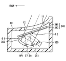
- the eighth embodiment is a modification of the second embodiment.
- the eighth embodiment will be described focusing on differences from the second embodiment.
- the image light emitting unit of the eighth embodiment is a laser display 820 for emitting laser light, as in the second embodiment.
- the laser display 820 includes one laser oscillator 821, one collimating lens 822, a scanning unit 824, and a screen member 825.
- the laser oscillator 821 oscillates a red laser beam having, for example, a peak wavelength in the range of 600 to 650 nm, preferably 640 nm.
- Each laser beam oscillated from the laser oscillator 821 enters the collimator lens 822.
- the collimating lens 822 substantially collimates the laser beam by refracting the laser beam.
- the laser beam thus transmitted through the collimating lens 822 enters the scanning unit 824, and is drawn on the scanning area SA of the screen member 825 as in the second embodiment.
- the laser display 820 emits display light having one peak wavelength WP corresponding to the peak wavelength of the red laser light flux toward the reflective / transmissive member 840.
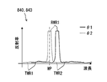
- the optical multilayer film 843 has a reflection wavelength region RWR1 and transmission wavelength regions TWR1 and TWR2 in the visible light region, as shown in FIG.
- the first transmission wavelength region TWR1, the first reflection wavelength region RWR1, and the second transmission wavelength regions TWR1 and TWR2 are set from the short wavelength side.
- the optical multilayer film 843 has a characteristic that the reflection wavelength region RWR1 and the transmission wavelength regions TWR1 and TWR2 shift in accordance with the incident angle of light, as in the second embodiment.
- the optical multilayer film 843 is configured such that the peak wavelength WP is included in the first transmission wavelength region TWR1 under the condition that the display light is incident at the first incident angle ⁇ 1.
- the spectral half-width of the peak wavelength WP of the display light is completely included in the first transmission wavelength region TWR1.
- the optical multilayer film 843 is configured such that the peak wavelength WP is included in the first reflection wavelength region RWR1 under the condition that the display light is incident at the second incident angle ⁇ 2.
- the spectral half-width of the peak wavelength WP of the display light is completely included in the first reflection wavelength region RWR1.
- the first incident angle ⁇ 1 is set so that one peak wavelength WP is included in the transmission wavelength region TWR1 at the first incidence, and the display light is transmitted through the reflection / transmission member 840.
- the second incident angle ⁇ 2 is set so that one peak wavelength WP is included in the reflection wavelength region RWR1 at the second incidence, and the display light is reflected by the reflection and transmission member 840. Therefore, the component of the peak wavelength WP constituting the display light is projected onto the projection unit 3a while securing the optical path length in the reciprocating optical path OP1 reliably, so that a virtual image VRI of high luminance is displayed while securing an easy-to-see distance. Can.
- the optical multilayer film 843 since the optical multilayer film 843 may be designed in consideration of one peak wavelength WP, the optical multilayer film 843 can be configured simply. As described above, the HUD device 100 having good visibility of the virtual image VRI can be easily provided.
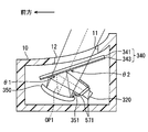
- the ninth embodiment As shown in FIGS. 19 and 20, the ninth embodiment is a modification of the eighth embodiment.
- the ninth embodiment will be described focusing on differences from the eighth embodiment.
- the ninth embodiment is, as shown in FIG. 19, a combination of the laser display 820 of the eighth embodiment and the arrangement of the reflective / transmissive member 340 and the reciprocating reflector 350 of the third embodiment.
- the configuration of the optical multilayer film 943 of the reflective / transmissive member 940 of the present embodiment is different from the configuration of the third and eighth embodiments.
- the optical multilayer film 943 has a reflection wavelength region RWR1 and transmission wavelength regions TWR1 and TWR2.
- the first transmission wavelength region TWR1, the first reflection wavelength region RWR1, and the second transmission wavelength region TWR2 are set from the short wavelength side.
- the optical multilayer film 943 has a characteristic that the reflection wavelength region RWR1 and the transmission wavelength regions TWR1 and TWR2 shift according to the incident angle of light, as in the eighth embodiment.
- the optical multilayer film 943 is configured such that the peak wavelength WP is included in the first reflection wavelength region RWR1 under the condition that the display light is incident at the first incident angle ⁇ 1.
- the spectral half-width of the peak wavelength WP of the display light is completely included in the first reflection wavelength region RWR1.
- the optical multilayer film 943 is configured such that the peak wavelength WP is included in the second transmission wavelength region TWR2 under the condition that the display light is incident at the second incident angle ⁇ 2.
- the spectral half-width of the peak wavelength WP of the display light is completely included in the second transmission wavelength region TWR2.
- the first incident angle ⁇ 1 is set so that one peak wavelength WP is included in the reflection wavelength region RWR1 at the first incidence, and the display light is reflected by the reflection and transmission member 340.
- the second incident angle ⁇ 2 is set so that one peak wavelength WP is included in the transmission wavelength region TWR2 at the second incidence, and the display light is transmitted through the reflection / transmission member 340. Therefore, the component of the main peak wavelength WP constituting the display light is projected to the projection unit 3a while securing the optical path length in the reciprocating optical path OP1 reliably, so that a high-brightness virtual image VRI is displayed while securing an easy-to-see distance. can do.
- the optical multilayer film 943 may be designed in consideration of one peak wavelength WP, the optical multilayer film 943 can be configured simply. As described above, the HUD device 100 having good visibility of the virtual image VRI can be easily provided.
- the image light emitting unit, the reflection and transmission member 40, the reciprocating reflection member 50, and the like may be arranged differently.
- the liquid crystal display 20 as an image light emitting unit emits display light from the front toward the rear.
- the reflective / transmissive member 40 is disposed obliquely in front of the liquid crystal display 20 so that the normal direction thereof is backward, downward, forward, and upward.
- the reflection surface 51 of the reciprocating reflection member 50 is disposed to face the rear in front of the reflection / transmission member 40.
- the image light emitting unit, the reflection and transmission member 40, the reciprocating reflection member 50, and the like may be arranged differently.
- the liquid crystal display 320 as an image light emitting unit emits display light from the front toward the rear.
- the reflective / transmissive member 340 is obliquely disposed rearward of the liquid crystal display 320 such that the normal direction thereof is forward, downward, backward, and upward.
- the reflection surface 351 of the reciprocating reflection member 350 is disposed below the reflection / transmission member 340 so as to face upward and slightly backward.
- the reflection wavelength regions RWR1, RWR2, RWR3 and the transmission wavelength regions TWR1, TWR2, TWR3 at the second incident are the first incident. It shifts to the longer wavelength side than that.
- the optical multilayer film 43 in the reflective / transmissive member 40 may be provided on either side of the light transmitting substrate 41.
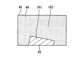
- the optical multilayer film 43 in the reflective / transmissive member 40 may be formed not on the entire surface of the reflective / transmissive member 40 but only on a partial region. As shown in FIGS. 25 and 26, the optical multilayer film 43 may be disposed only in the first incident region IR1, and a region other than the first incident region IR1 in the reflective / transmissive member 40 serves as the reflective surface 51 such as aluminum.
- the metal film may be formed by depositing the metal of Further, as shown in FIG. 26, a part of the display light may pass through the reflective / transmissive member 40, and the other part may pass through the side of the reflective / transmissive member 40 as it is to reach the reciprocating optical path OP1.
- the surface on which the display light is transmitted such as the surface of the reflective / transmissive member 40 on the side where the optical multilayer film 43 is not provided and each surface of the dustproof sheet 12, is different from the optical multilayer film 43.
- An optical multilayer film may be provided to prevent light reflection.
- the reflection / transmission member 40 may be formed in a curved plate shape, and the surface thereof is a spherical surface, a cylindrical surface, or a free-form surface including a saddle point. It may be formed in a shape or the like.
- the reflecting surface 51 of the reciprocating reflecting member 50 may be formed into a spherical shape, a cylindrical surface, or a free curved surface including a saddle point.
- a direction changing unit 57 that changes the direction of the reflective / transmissive member 40 or the reciprocating reflective member 50 may be further provided.
- the direction changing unit 57 rotates the reflective / transmissive member 40 or the reciprocating reflective member 50 around a rotation axis 58 extending in the left-right direction using a stepping motor, for example, of the reflective / transmissive member 40 or the reciprocating reflective member 50. It is possible to change the direction.
- the direction of the reflective / transmissive member 40 or the reciprocal reflective member 50 is a range in which the relationship between the peak wavelengths WP1, WP2, WP3 and the reflected wavelength regions RWR1, RWR2, RWR3 and the transmitted wavelength regions TWR1, TWR2, TWR3 is maintained. That is, it is preferable to be changed in the range in which the functions of transmission and reflection of display light are not switched.
- the traveling direction of the display light after the second incidence is changed. Therefore, the position where the virtual image VRI is displayed in the projection unit 3a is changed up and down.
- the reflection / transmission member 440 which is also used as a dustproof sheet may be formed in a curved plate shape.
- the light blocking laminated portion 573 may be provided by forming a coating film on a light shielding film or the reflective transmission member 40 other than polyurethane, for example.
- a display other than a liquid crystal display and a laser display for example, a DLP (Digital Light Processing (registered trademark)) display can be adopted as an image light emitting unit.
- a DLP display light from a light emitting element is directed to an array of minute digital mirror elements that can be switched between on and off states, and light is reflected by only the on state digital mirror elements. Is formed, and the display light of the image is emitted.
- the display light emitted by the image light emitting unit may have one peak wavelength at the green wavelength or the blue wavelength.
- the display light may have two or four or more peak wavelengths in the visible light region.
- the light blocking hood portion 571 as in the fifth embodiment is applied to the configurations of the image light emitting portion, the reflective / transmissive member 340, and the reciprocating reflective member 350 of the third, fourth, and ninth embodiments. May be In this case, as shown in FIG. 31, the light blocking hood portion 571 is preferably disposed so as not to interfere with the reciprocating optical path OP1.
- the configuration of the image light emitting unit, the reflection / transmission member 340, and the reciprocating reflection member 350 of the third, fourth, and ninth embodiments is similar to that of the sixth embodiment.
- the reciprocating reflection member holding wall 613 and the reflection / transmission member holding wall 614 may be applied.
- a convex mirror as in the seventh embodiment. 775 may be applied.
- the second incident angle ⁇ 2 is set smaller than the first incident angle ⁇ 1.
- the virtual image display device can be applied to various vehicles such as an aircraft, a ship, or a housing that does not move.
Landscapes
- Physics & Mathematics (AREA)
- Engineering & Computer Science (AREA)
- General Physics & Mathematics (AREA)
- Optics & Photonics (AREA)
- Chemical & Material Sciences (AREA)
- Combustion & Propulsion (AREA)
- Transportation (AREA)
- Mechanical Engineering (AREA)
- Instrument Panels (AREA)
- Mechanical Optical Scanning Systems (AREA)
Abstract
This virtual image display device comprises: a reflective transmission member (40) which, by comprising an optical multilayer film (43), has a reflection wavelength region serving as a wavelength region that reflects light, and a transmission wavelength region serving as a wavelength region that transmits light; a liquid crystal display device (20) that emits display light of an image to the reflective transmission member; and a reciprocating reflection member (50) constituting a reciprocating optical path (OP1) where the display light is caused to reciprocate between the reflective transmission member and the reciprocating reflection member by reflecting the display light traveling via the reflective transmission member back to the reflective transmission member. A HUD device (100) utilizes a shift action by which the reflection wavelength region and the transmission wavelength region are shifted by causing a first incident angle (θ1) and a second incident angle (θ2) which are incident on the optical multilayer film to differ, and as a result thereof, first incident display light of the first incident angle is guided to the reciprocating reflection member side of the reciprocating optical path, and second incident display light of the second incident angle is guided to a projection unit (3a). The foregoing makes it possible to improve the visibility of a virtual image.
Description
本出願は、当該開示内容が参照によって本出願に組み込まれた、2017年10月30日に出願された日本特許出願2017-209574号を基にしている。
This application is based on Japanese Patent Application No. 2017-209574 filed Oct. 30, 2017, the disclosure of which is incorporated by reference into the present application.
本開示は、画像を視認可能に虚像表示する虚像表示装置に関する。
The present disclosure relates to a virtual image display device that displays a virtual image in a viewable manner.
従来、投影部へ画像を投影することにより、画像を視認可能に虚像表示する虚像表示装置が知られている。特許文献1に開示の虚像表示装置は、凹面鏡、画像発光部、及び反射ミラーを有している。凹面鏡の少なくとも一部には、ハーフミラーからなるハーフミラー領域が設けられている。画像発光部は、画像の表示光をハーフミラー領域へ向けて発する。反射ミラーは、ハーフミラー領域を透過した表示光を反射ミラーへ向けて反射することにより、凹面鏡との間に表示光を往復させる往復光路を構成している。反射ミラーに反射された表示光は、ハーフミラー領域を含む凹面鏡にて投影部側へ反射される。こうして投影部へ画像が投影される。
2. Description of the Related Art Conventionally, there is known a virtual image display device that displays a virtual image so that the image can be viewed visually by projecting the image onto a projection unit. The virtual image display device disclosed in Patent Document 1 includes a concave mirror, an image light emitting unit, and a reflection mirror. At least a part of the concave mirror is provided with a half mirror area consisting of a half mirror. The image light emitting unit emits display light of the image toward the half mirror area. The reflection mirror forms a reciprocating light path for reciprocating the display light with the concave mirror by reflecting the display light transmitted through the half mirror region toward the reflection mirror. The display light reflected by the reflection mirror is reflected toward the projection unit by the concave mirror including the half mirror area. Thus, the image is projected to the projection unit.
このように、特許文献1の装置では、往復光路を構成することで、光路長を稼ぎながら装置を小型化することが試みられている。しかしながら、虚像の一部を構成する表示光は、ハーフミラー領域を1回透過し、さらに1回反射することとなるため、透過及び反射の度に表示光が例えば半分程度に減衰してしまう。すなわち表示光が投射後に4分の1以下に減衰してしまう程エネルギー効率が悪く、虚像に十分な輝度が得られない。したがって、視認性が良好な虚像を表示することが困難であった。
As described above, in the device of Patent Document 1, attempts are made to miniaturize the device while earning the optical path length by constructing a reciprocating light path. However, since the display light which constitutes a part of the virtual image is transmitted once in the half mirror region and reflected one more time, the display light is attenuated by, for example, about half at each transmission and reflection. That is, the energy efficiency is so low that the display light attenuates to a quarter or less after projection, and a sufficient brightness for the virtual image can not be obtained. Therefore, it was difficult to display a virtual image with good visibility.
開示されるひとつの目的は、虚像の視認性が良好な虚像表示装置を提供することにある。
One object disclosed is to provide a virtual image display device with good visibility of a virtual image.
ここに開示された虚像表示装置は、投影部へ画像を投影することにより、画像を視認可能に虚像表示する虚像表示装置であって、
光学膜を積層してなる光学多層膜が設けられていることにより、光を反射させる波長領域としての反射波長領域と、光を透過させる波長領域としての透過波長領域と、を有する反射透過部材と、
画像の表示光を、反射透過部材へ向けて発する画像発光部と、
反射透過部材を経由した表示光を再び反射透過部材へ向けて反射することにより、反射透過部材との間に表示光を往復させる往復光路を構成する往復反射部材と、を備え、
画像発光部側から反射透過部材の光学多層膜への表示光の第1入射角による入射を第1入射と定義し、往復光路の往復反射部材側から反射透過部材の光学多層膜への表示光の第2入射角による入射を第2入射と定義すると、
第1入射角と第2入射角とを異ならせることで反射波長領域及び透過波長領域がシフトするシフト作用を利用して、第1入射にて表示光を往復光路の往復反射部材側へ導くと共に、第2入射にて表示光を投影部側へ導く。 The virtual image display device disclosed herein is a virtual image display device that displays a virtual image so that the image can be viewed visually by projecting the image onto the projection unit.
A reflective / transmissive member having a reflection wavelength region as a wavelength region for reflecting light and a transmission wavelength region as a wavelength region for transmitting light by being provided with an optical multilayer film formed by laminating optical films ,
An image light emitting unit that emits display light of an image toward the reflective / transmissive member;
And reciprocate reflection member constituting a reciprocation light path for causing display light to reciprocate between it and the reflection / transmission member by reflecting the display light having passed through the reflection / transmission member toward the reflection / transmission member again,
The first incident angle of the display light from the image light emitting portion side to the optical multilayer film of the reflective / transmissive member is defined as the first incidence, and the display light from the reciprocating reflective member side of the reciprocating light path to the optical multilayer film of the reflective / transmissive member If the incident by the second incident angle of is defined as the second incident,
The display light is guided to the reciprocation reflection member side of the reciprocation light path at the first incidence by utilizing the shift action of shifting the reflection wavelength region and the transmission wavelength region by making the first incidence angle and the second incidence angle different. And guide the display light to the projection unit side at the second incidence.
このような虚像表示装置によると、反射透過部材へ表示光の第1入射角と、第2入射角とが互いに異なっている。こうした入射角の差異により、反射透過部材に設けられた光学多層膜により実現された反射波長領域及び透過波長領域は、シフトすることとなる。このようなシフト作用を利用して、第1入射にて表示光が往復光路の往復反射部材側へ導かれると共に、第2入射にて表示光が投影部側へ導かれる。
According to such a virtual image display device, the first incident angle of the display light to the reflective / transmissive member is different from the second incident angle. Due to the difference in the incident angle, the reflection wavelength region and the transmission wavelength region realized by the optical multilayer film provided in the reflection and transmission member are shifted. Using such a shift action, the display light is guided to the reciprocating reflection member side of the reciprocating light path at the first incidence, and the display light is guided to the projection unit side at the second incidence.
詳細に、表示光が第1入射角で入射する条件下、当該表示光の波長が反射波長領域及び透過波長領域のうち一方に該当していれば、表示光が第2入射角で入射する条件下で当該表示光の波長が反射波長領域及び透過波長領域のうち他方に該当するように、入射角を互いに異ならせることで、光学多層膜が表示光に及ぼす透過作用及び反射作用を切り替える。こうして、表示光が反射透過部材に入射する際に、それぞれ高い割合で所望の方向へ導くことができるようになる。故に、表示光の減衰を抑制しつつ光路長を稼ぐための往復光路を構成することが可能となるので、見易い距離を確保しつつ高輝度の虚像を表示することができる。以上により、虚像の視認性が良好な虚像表示装置を提供することができる。
Specifically, under the condition that the display light is incident at the first incident angle, the condition that the display light is incident at the second incident angle if the wavelength of the display light falls under one of the reflection wavelength region and the transmission wavelength region. The transmission action and the reflection action of the optical multilayer film on the display light are switched by making the incident angles different from each other so that the wavelength of the display light falls under the other of the reflection wavelength region and the transmission wavelength region below. Thus, when the display light is incident on the reflection / transmission member, it can be guided in the desired direction at a high rate. Therefore, since it is possible to form a reciprocating light path for obtaining an optical path length while suppressing the attenuation of display light, it is possible to display a high-luminance virtual image while securing an easy-to-see distance. According to the above, it is possible to provide a virtual image display device with good visibility of the virtual image.
以下、複数の実施形態を図面に基づいて説明する。なお、各実施形態において対応する構成要素には同一の符号を付すことにより、重複する説明を省略する場合がある。各実施形態において構成の一部分のみを説明している場合、当該構成の他の部分については、先行して説明した他の実施形態の構成を適用することができる。また、各実施形態の説明において明示している構成の組み合わせばかりではなく、特に組み合わせに支障が生じなければ、明示していなくても複数の実施形態の構成同士を部分的に組み合せることができる。
Hereinafter, a plurality of embodiments will be described based on the drawings. In addition, the overlapping description may be abbreviate | omitted by attaching the same code | symbol to the corresponding component in each embodiment. When only a part of the configuration is described in each embodiment, the configuration of the other embodiments described above can be applied to other parts of the configuration. In addition to the combinations of the configurations explicitly described in the description of each embodiment, the configurations of the plurality of embodiments can be partially combined with each other even if they are not explicitly specified unless any problem occurs in the combination. .
(第1実施形態)
図1に示すように、本開示の第1実施形態による虚像表示装置は、車両1に用いられ、当該車両1のインストルメントパネル2内に収容されているヘッドアップディスプレイ装置(以下、HUD装置)100となっている。HUD装置100は、車両1のウインドシールド3に設定された投影部3aへ向けて画像を投影する。これにより、HUD装置100は、画像を、視認者としての乗員により視認可能に虚像表示する。すなわち、投影部3aにて反射される画像の表示光が、車両1の室内に設定された視認領域EBに到達することにより、視認領域EBにアイポイントEPが位置する乗員が当該表示光を虚像VRIとして知覚する。そして、乗員は、虚像VRIとして表示される各種情報を認識することができる。画像として虚像表示される各種情報としては、例えば車速、燃料残量等の車両1の状態を示す情報、又は視界補助情報、道路情報等のナビゲーション情報等が挙げられる。 First Embodiment
As shown in FIG. 1, the virtual image display device according to the first embodiment of the present disclosure is used in avehicle 1 and is a head-up display device (hereinafter referred to as HUD device) housed in an instrument panel 2 of the vehicle 1. It is 100. The HUD device 100 projects an image toward the projection unit 3 a set on the windshield 3 of the vehicle 1. Thus, the HUD device 100 displays an image as a virtual image so as to be visible by an occupant as a viewer. That is, when the display light of the image reflected by the projection unit 3a reaches the viewing area EB set in the room of the vehicle 1, the occupant whose eye point EP is located in the viewing area EB is a virtual image of the display light Perceive as VRI. Then, the occupant can recognize various information displayed as a virtual image VRI. Examples of various information displayed as a virtual image as an image include information indicating the state of the vehicle 1 such as the vehicle speed and the remaining amount of fuel, or navigation information such as visibility auxiliary information and road information.
図1に示すように、本開示の第1実施形態による虚像表示装置は、車両1に用いられ、当該車両1のインストルメントパネル2内に収容されているヘッドアップディスプレイ装置(以下、HUD装置)100となっている。HUD装置100は、車両1のウインドシールド3に設定された投影部3aへ向けて画像を投影する。これにより、HUD装置100は、画像を、視認者としての乗員により視認可能に虚像表示する。すなわち、投影部3aにて反射される画像の表示光が、車両1の室内に設定された視認領域EBに到達することにより、視認領域EBにアイポイントEPが位置する乗員が当該表示光を虚像VRIとして知覚する。そして、乗員は、虚像VRIとして表示される各種情報を認識することができる。画像として虚像表示される各種情報としては、例えば車速、燃料残量等の車両1の状態を示す情報、又は視界補助情報、道路情報等のナビゲーション情報等が挙げられる。 First Embodiment
As shown in FIG. 1, the virtual image display device according to the first embodiment of the present disclosure is used in a
以下において、特に断り書きが無い限り、前方、後方、前後方向、上方、下方、上下方向、左方、右方、及び左右方向は、水平面HP上の車両1を基準として表記される。
In the following, unless stated otherwise, the front, rear, front-rear direction, upper, lower, vertical, left, right, and left-right directions are described with reference to the vehicle 1 on the horizontal plane HP.
車両1のウインドシールド3は、例えばガラスないしは合成樹脂により透光性の板状に形成され、インストルメントパネル2よりも上方に配置されている。ウインドシールド3は、表示光が投影される投影部3aを、滑らかな凹面状又は平面状に形成している。なお、投影部3aは、ウインドシールド3に設けられていなくてもよい。例えば車両1と別体となっているコンバイナを車両1内に設置して、当該コンバイナに投影部3aが設けられていてもよい。
The windshield 3 of the vehicle 1 is formed of, for example, glass or synthetic resin in a translucent plate shape, and is disposed above the instrument panel 2. The windshield 3 forms the projection part 3a on which the display light is projected in a smooth concave or planar shape. The projection unit 3 a may not be provided on the windshield 3. For example, a combiner that is separate from the vehicle 1 may be installed in the vehicle 1, and the projector 3a may be provided in the combiner.
視認領域EBは、HUD装置100により表示される虚像VRIが所定の規格を満たすように視認可能となる空間領域であって、アイボックスとも称される。視認領域EBは、典型的には、車両1に設定されたアイリプスと重なるように設定される。アイリプスは、乗員のアイポイントEPの空間分布を統計的に表したアイレンジに基づいて、楕円体状に設定されている。
The visual recognition area EB is a space area that can be visually recognized so that the virtual image VRI displayed by the HUD device 100 satisfies a predetermined standard, and is also referred to as an eye box. The visual recognition area EB is typically set to overlap the eyedrops set in the vehicle 1. The eye drops are set in an ellipsoidal shape based on an eye range that statistically represents the spatial distribution of the eye point EP of the occupant.
このようなHUD装置100の具体的構成を、図2~7も用いて、以下に説明する。HUD装置100は、図2,3に示すように、ハウジング10、画像学校部としての液晶表示器20、反射透過部材40及び往復反射部材50等により構成されている。本HUD装置100は、小型化が図られているため、車両1への搭載性が良好なものとなっている。
The specific configuration of such a HUD device 100 will be described below using FIGS. 2 to 7 as well. As shown in FIGS. 2 and 3, the HUD device 100 includes a housing 10, a liquid crystal display 20 as an image school unit, a reflection / transmission member 40, a reciprocating reflection member 50, and the like. Since the HUD device 100 can be downsized, it can be easily mounted on the vehicle 1.
ハウジング10は、例えば合成樹脂ないしは金属により、例えば液晶表示器20、往復反射部材50等のHUD装置100の他の要素を収容する中空形状を有しており、車両1のインストルメントパネル2内に設置されている。ハウジング10は、投影部3aと対向する上面部に、光学的に開口する窓部11を有している。窓部11は、表示光を透過可能な防塵シート12で覆われている。
The housing 10 is made of, for example, a synthetic resin or metal, and has a hollow shape that accommodates the other elements of the HUD device 100 such as the liquid crystal display 20 and the reciprocating reflection member 50. is set up. The housing 10 has a window 11 which is optically opened on the upper surface facing the projection 3a. The window portion 11 is covered with a dustproof sheet 12 capable of transmitting display light.
画像発光部は、虚像VRIとして結像される画像の表示光を、反射透過部材40へ向けて、発光する。本実施形態の画像発光部は、液晶表示器20となっている。液晶表示器20は、バックライト部21及び液晶パネル26を有し、例えば箱状のケーシング20aにこれらを収容して構成されている。図4に示すようにバックライト部21は、例えば、光源22、コンデンサレンズ23、及びフィールドレンズ24等により構成されている。
The image light emitting unit emits display light of an image formed as a virtual image VRI toward the reflection and transmission member 40. The image light emitting unit of the present embodiment is a liquid crystal display 20. The liquid crystal display 20 has a back light portion 21 and a liquid crystal panel 26, and is configured by, for example, accommodating them in a box-like casing 20a. As shown in FIG. 4, the backlight unit 21 includes, for example, a light source 22, a condenser lens 23, a field lens 24, and the like.
光源22は、例えば複数の発光素子22aを配列することにより構成されている。本実施形態における発光素子22aは、光源用回路基板22b上に配置され、電源と接続されている発光ダイオード素子である。各発光素子22aは、通電により電流量に応じた発光量で光を発光する。詳細には、各発光素子22aは、例えば青色発光ダイオードを黄色蛍光体で覆うことにより、疑似白色での発光が実現されている。
The light source 22 is configured, for example, by arranging a plurality of light emitting elements 22 a. The light emitting element 22 a in the present embodiment is a light emitting diode element disposed on the light source circuit board 22 b and connected to a power supply. Each light emitting element 22 a emits light with a light emission amount corresponding to the amount of current when it is energized. In detail, in each light emitting element 22a, for example, pseudo white light emission is realized by covering a blue light emitting diode with a yellow phosphor.
コンデンサレンズ23及びフィールドレンズ24は、光源22と液晶パネル26との間に配置されている。コンデンサレンズ23は、例えば合成樹脂ないしはガラス等により透光性を有して形成されている。特に本実施形態のコンデンサレンズ23は、複数の凸レンズ素子が発光素子22aの数及び配置に合わせて配列されたレンズアレイとなっている。コンデンサレンズ23は、光源22側から入射した光を集光してフィールドレンズ24側へ射出する。
The condenser lens 23 and the field lens 24 are disposed between the light source 22 and the liquid crystal panel 26. The condenser lens 23 is formed of, for example, a synthetic resin or glass so as to be translucent. In particular, the condenser lens 23 of the present embodiment is a lens array in which a plurality of convex lens elements are arranged in accordance with the number and arrangement of the light emitting elements 22a. The condenser lens 23 condenses the light incident from the light source 22 side and emits the light to the field lens 24 side.
フィールドレンズ24は、コンデンサレンズ23と液晶パネル26との間に配置され、例えば合成樹脂ないしはガラス等により透光性を有して形成されている。フィールドレンズ24は、コンデンサレンズ23側から入射した光をさらに集光して、液晶パネル26側へ向けて射出する。
The field lens 24 is disposed between the condenser lens 23 and the liquid crystal panel 26, and is formed of, for example, a synthetic resin or glass to have translucency. The field lens 24 further condenses the light incident from the condenser lens 23 side, and emits the light toward the liquid crystal panel 26 side.
なお、バックライト部21の構成としては、上述の構成以外にも、種々の構成を採用することができる。
In addition, as a structure of the backlight part 21, various structures can be employ | adopted besides the above-mentioned structure.
本実施形態の液晶パネル26は、薄膜トランジスタ(Thin Film Transistor、TFT)を用いた液晶パネルであって、例えば2次元方向に配列された複数の液晶画素から形成されたアクティブマトリクス型の液晶パネルである。液晶パネル26は、一対の直線偏光板27a,27b及び一対の直線偏光板27a,27bに挟まれた液晶層等が積層されている。各直線偏光板27a,27bは、透過軸に沿った方向の偏光を透過させると共に、透過軸とは直交する吸収軸に沿った方向の偏光を遮光する性質を有している。一対の直線偏光板27a,27bは、透過軸を互いに実質直交して配置されている。液晶層は、液晶画素毎の電圧印加により、印加電圧に応じて液晶層に入射する光の偏光方向を回転させることが可能となっている。
The liquid crystal panel 26 of the present embodiment is a liquid crystal panel using thin film transistors (TFTs), and is, for example, an active matrix liquid crystal panel formed of a plurality of liquid crystal pixels arranged in a two-dimensional direction. . In the liquid crystal panel 26, a liquid crystal layer or the like sandwiched between a pair of linear polarizing plates 27a and 27b and a pair of linear polarizing plates 27a and 27b is stacked. Each of the linear polarization plates 27a and 27b transmits light polarized in a direction along the transmission axis and shields light polarized in a direction along an absorption axis orthogonal to the transmission axis. The pair of linear polarization plates 27a and 27b are disposed such that the transmission axes are substantially orthogonal to each other. The liquid crystal layer is capable of rotating the polarization direction of light incident on the liquid crystal layer according to the applied voltage by voltage application for each liquid crystal pixel.
液晶パネル26は、バックライト部21からの光の入射により、液晶画素毎の当該光の透過率を制御して、表示画面28から射出される表示光によって画像を形成することが可能となっている。ここで、表示光は、射出側の直線偏光板27bの透過軸に沿った直線偏光として、表示画面28から射出される。
The liquid crystal panel 26 can form an image by display light emitted from the display screen 28 by controlling the transmittance of the light for each liquid crystal pixel when the light from the backlight unit 21 is incident. There is. Here, the display light is emitted from the display screen 28 as linearly polarized light along the transmission axis of the linear polarizing plate 27b on the emission side.
より詳細に、隣り合う液晶画素には、互いに異なる色(例えば、赤色、緑色、及び青色)のカラーフィルタが設けられており、これらの組み合わせにより様々な色が実現されるようになっている。各色のカラーフィルタは、それぞれに固有の透過率の波長特性を有しており、透過率が最大となる透過率最大波長を、互いに異ならせて設定されている。
More specifically, adjacent liquid crystal pixels are provided with color filters of different colors (for example, red, green, and blue), and various colors are realized by a combination of these. The color filters of each color have their own wavelength characteristics of transmittance, and the maximum transmittance wavelengths at which the transmittance is maximum are set to be different from each other.
したがって、バックライト部21から液晶パネル26を透過して発せられた表示光は、表示される画像にも依存するものの、例えば図5に示されるような複数のピーク波長WP1,WP2,WP3を有するものとなっている。ここで表示光の複数のピーク波長WP1,WP2,WP3は、各カラーフィルタの透過率最大波長に対応しており、例えば青色のカラーフィルタに対応する約450nm、緑色のカラーフィルタに対応する約530nm、及び赤色のカラーフィルタに対応する約600nmにそれぞれ対応している。本実施形態の表示光は、3つのピーク波長WP1,WP2,WP3を有しつつも、可視光領域の大半において連続的なスペクトルを有するものとなっている。
Therefore, although the display light emitted from the backlight unit 21 through the liquid crystal panel 26 depends on the displayed image, it has a plurality of peak wavelengths WP1, WP2 and WP3 as shown in FIG. 5, for example. It has become a thing. Here, the plurality of peak wavelengths WP1, WP2, and WP3 of the display light correspond to the transmission maximum wavelengths of the respective color filters, for example, about 450 nm corresponding to the blue color filter, and about 530 nm corresponding to the green color filter. , And corresponding to about 600 nm corresponding to red color filters. The display light of this embodiment has three peak wavelengths WP1, WP2 and WP3 but has a continuous spectrum in most of the visible light region.
こうして本実施形態の液晶表示器20は、前方から後方へ向けて表示光を発するようになっている。
Thus, the liquid crystal display 20 of the present embodiment emits display light from the front toward the rear.
反射透過部材40は、図2,6に示すように、例えば透光基板41の片側全面に光学多層膜43を形成した平板状を呈している。本実施形態の反射透過部材40は、液晶表示器20よりも後方において、その法線方向が前方かつ下方及び後方かつ上方を向くように、傾斜配置されている。透光基板41は、例えば合成樹脂ないしはガラス等により、透過率が高い透光性の平板状に形成されている。
As shown in FIGS. 2 and 6, the reflective / transmissive member 40 has, for example, a flat plate shape in which an optical multilayer film 43 is formed on the entire surface on one side of the light transmitting substrate 41. The reflection / transmission member 40 of the present embodiment is disposed obliquely rearward of the liquid crystal display 20 so that the normal direction thereof is forward, downward, backward, and upward. The light transmitting substrate 41 is formed of, for example, a synthetic resin or glass in a light transmitting flat plate shape having a high transmittance.
光学多層膜43は、例えば、反射透過部材40の表面のうち、液晶表示器20とは反対側の表面(すなわち往復反射部材50側の表面)に、蒸着、スピンコートないしはフィルムを貼り付けること等により形成されている。光学多層膜43は、2種類以上の互いに屈折率の異なる光学材料からなる薄膜状の光学膜を、反射透過部材40の表面の法線方向に沿って積層して形成されている。光学膜としては、例えば、酸化チタン(TiO2)、酸化シリコン(SiO2)、酸化ニオブ(Nb2O5)、酸化タンタル(Ta2O5)、フッ化マグネシウム(MgF2)、フッ化カルシウム(CaF2)等を採用することが可能である。本実施形態の光学多層膜43は、酸化チタンからなる光学膜と、酸化シリコンからなる光学膜とを、交互に積層して形成されている。
The optical multilayer film 43 may be formed by, for example, depositing, spin coating, or attaching a film to the surface of the reflective / transmissive member 40 opposite to the liquid crystal display 20 (that is, the surface on the reciprocating reflective member 50 side) It is formed by The optical multilayer film 43 is formed by laminating thin-film-like optical films made of optical materials of two or more types different in refractive index along the normal direction of the surface of the reflective / transmissive member 40. As the optical film, for example, titanium oxide (TiO 2), silicon oxide (SiO 2), niobium oxide (Nb 2 O 5), tantalum oxide (Ta 2 O 5), magnesium fluoride (MgF 2), calcium fluoride (CaF 2) or the like may be employed. It is possible. The optical multilayer film 43 of the present embodiment is formed by alternately laminating an optical film made of titanium oxide and an optical film made of silicon oxide.
各光学膜における各膜厚は、事前にコンピュータにより、光の干渉をシミュレートした最適化計算によって適宜設定される。したがって、反射透過部材40の反射率の波長特性及び透過率の波長特性は、当該光学多層膜43における光の干渉の結果に基づいて特徴づけられている。
Each film thickness in each optical film is appropriately set in advance by optimization calculation that simulates light interference by a computer. Therefore, the wavelength characteristics of the reflectance and the wavelength characteristics of the transmittance of the reflective / transmissive member 40 are characterized based on the result of the light interference in the optical multilayer film 43.
具体的に図7に示すように、反射透過部材40は、虚像表示に実際に寄与する可視光領域において、光を反射させる波長領域としての反射波長領域RWR1,RWR2,RWR3、及び光を透過させる波長領域としての透過波長領域TWR1,TWR2,TWR3を、交互に有している。反射波長領域RWR1,RWR2,RWR3及び透過波長領域TWR1,TWR2,TWR3は、それぞれ表示光のピーク波長WP1,WP2,WP3と同数以上構成されている。例えば本実施形態では、短波長側から、第1の透過波長領域TWR1、第1の反射波長領域RWR1、第2の透過波長領域TWR2、第2の反射波長領域RWR2、第3の透過波長領域TWR3、及び第3の反射波長領域RWR3が交互に設定されている。
Specifically, as shown in FIG. 7, in the visible light region that actually contributes to virtual image display, as shown in FIG. 7, the reflection wavelength regions RWR 1, RWR 2, RWR 3 as light wavelength regions and light are transmitted. Transmission wavelength regions TWR1, TWR2 and TWR3 as wavelength regions are alternately provided. The reflection wavelength regions RWR1, RWR2, RWR3 and the transmission wavelength regions TWR1, TWR2, TWR3 are respectively configured to have the same number or more as the peak wavelengths WP1, WP2, WP3 of the display light. For example, in the present embodiment, from the short wavelength side, the first transmission wavelength range TWR1, the first reflection wavelength range RWR1, the second transmission wavelength range TWR2, the second reflection wavelength range RWR2, the third transmission wavelength range TWR3. , And the third reflection wavelength region RWR3 are set alternately.
なお、詳細は図示しないが、第1の透過波長領域TWR1よりも短波長側に、別の反射波長領域等が設定されていてもよく、第3の反射波長領域RWR3よりも長波長側に、別の透過波長領域等が設定されていてもよい。
Although not shown in detail, another reflection wavelength region or the like may be set on the shorter wavelength side than the first transmission wavelength region TWR1, and the other reflection wavelength region may be set on the longer wavelength side than the third reflection wavelength region RWR3. Another transmission wavelength region or the like may be set.
図2に示すように、反射透過部材40に、液晶表示器20からの表示光は、斜め入射する。ここで、液晶表示器20側からの反射透過部材40の光学多層膜43への入射を第1入射と定義し、第1入射における表示光の光学多層膜43への入射角を第1入射角θ1と定義する。光学多層膜43は、図7に示すように、第1入射角θ1で表示光が入射する条件下、各ピーク波長WP1,WP2,WP3が透過波長領域TWR1,TWR2,TWR3に含まれるように構成されている。詳細に、青色のカラーフィルタに対応する約450nmのピーク波長WP1が第1の透過波長領域TWR1に含まれ、緑色のカラーフィルタに対応する約530nmのピーク波長WP2が第2の透過波長領域TWR2に含まれ、及び赤色のカラーフィルタに対応する約600nmのピーク波長WP3が第3の透過波長領域TWR3に含まれている。
As shown in FIG. 2, display light from the liquid crystal display 20 is obliquely incident on the reflective / transmissive member 40. Here, the incidence to the optical multilayer film 43 of the reflective transmission member 40 from the liquid crystal display 20 side is defined as the first incidence, and the incidence angle to the optical multilayer film 43 of the display light at the first incidence is the first incidence angle It is defined as θ1. The optical multilayer film 43 is configured such that the peak wavelengths WP1, WP2 and WP3 are included in the transmission wavelength regions TWR1, TWR2 and TWR3 under the condition that the display light is incident at the first incident angle θ1 as shown in FIG. It is done. In detail, the peak wavelength WP1 of about 450 nm corresponding to the blue color filter is included in the first transmission wavelength range TWR1, and the peak wavelength WP2 of about 530 nm corresponding to the green color filter is included in the second transmission wavelength range TWR2. A peak wavelength WP3 of about 600 nm, which is included and corresponds to the red color filter, is included in the third transmission wavelength range TWR3.
各透過波長領域TWR1,TWR2,TWR3では、反射率が50%以下、より好適には反射率が20%以下に設定されている結果、表示光全体に対しても、反射率が50%以下、より好適には20%以下となっている。換言すると、第1入射においては、表示光が50%以上、より好適には80%以上の透過率で反射透過部材40を透過するようになっている。なお、ここでいう反射率はエネルギー反射率であり、透過率はエネルギー透過率であるものとする。こうして反射透過部材40を透過した表示光の先には、往復反射部材50が配置されている。
In each of the transmission wavelength regions TWR1, TWR2 and TWR3, the reflectance is set to 50% or less, more preferably 20% or less. As a result, the reflectance to the entire display light is 50% or less, More preferably, it is 20% or less. In other words, at the first incidence, the display light is transmitted through the reflection / transmission member 40 with a transmittance of 50% or more, more preferably 80% or more. Here, the reflectance is the energy reflectance, and the transmittance is the energy transmittance. In the end of the display light transmitted through the reflection / transmission member 40 in this manner, the reciprocating reflection member 50 is disposed.
往復反射部材50は、図2,3に示すように、例えば合成樹脂ないしはガラス等からなる基材の表面に、反射面51としてアルミニウム等の金属を蒸着させることにより金属膜を形成した反射鏡となっている。反射面51は、曲面状に形成されており、例えば往復反射部材50の中心が凹むように凹面状に湾曲している。すなわち、往復反射部材50は、正の光学パワーを有する正の光学素子となっている。本実施形態の反射面51は、反射透過部材40よりも後方において、前方を向くように配置されている。
As shown in FIGS. 2 and 3, the reciprocating reflection member 50 has a reflecting mirror in which a metal film such as aluminum is deposited as a reflecting surface 51 on the surface of a base material made of synthetic resin or glass, for example. It has become. The reflecting surface 51 is formed in a curved shape, and is curved in a concave shape such that the center of the reciprocating reflecting member 50 is recessed, for example. That is, the reciprocating reflection member 50 is a positive optical element having a positive optical power. The reflective surface 51 of the present embodiment is disposed to face the front at the rear of the reflective / transmissive member 40.
往復反射部材50は、液晶表示器20側から反射透過部材40を経由した表示光を再び反射透過部材40へ向けて、高い反射率で反射する。こうして往復反射部材50は、反射透過部材40との間に表示光を往復させる往復光路OP1を構成している。往復光路OP1が構成されることにより、反射面51への入射角及び反射角が小さくなるように(例えば10~15度の範囲)、反射透過部材40及び往復反射部材50を配置することが可能となる。こうした反射面51への入射角及び反射角の設定により、往復光路OP1の復路では、往復光路OP1の往路よりも表示光の向きが若干上方を向くように修正される。
The reciprocating reflection member 50 reflects the display light, which has passed through the reflection / transmission member 40 from the liquid crystal display 20 side, toward the reflection / transmission member 40 again, with high reflectance. Thus, the reciprocating reflection member 50 constitutes a reciprocating light path OP1 for causing the display light to reciprocate between itself and the reflection / transmission member 40. By constructing the reciprocating optical path OP1, it is possible to arrange the reflective / transmissive member 40 and the reciprocating reflective member 50 so that the incident angle and the reflection angle to the reflective surface 51 become smaller (for example, in the range of 10 to 15 degrees). It becomes. By setting the incident angle and the reflection angle on the reflection surface 51, the direction of the display light is corrected to be slightly upward in the return path of the reciprocating optical path OP1 than the outward path of the reciprocating optical path OP1.
こうして表示光は、再び反射透過部材40に斜め入射する。ここで、往復光路OP1の往復反射部材50側から反射透過部材40の光学多層膜43への入射を第2入射と定義し、第2入射における表示光の光学多層膜43への入射角を第2入射角θ2と定義する。そうすると、第2入射角θ2は、第1入射角θ1と異なり、特に本実施形態では第1入射角θ1よりも大きくなっている。第2入射角θ2と第1入射角θ1との差分は、反射面51への入射角の2倍程度となるので、例えば20~30度の範囲に設定されている。
Thus, the display light is obliquely incident on the reflection / transmission member 40 again. Here, the incidence to the optical multilayer film 43 of the reflective transmission member 40 from the side of the reciprocal reflection member 50 of the reciprocating optical path OP1 is defined as the second incidence, and the incident angle of the display light at the second incidence to the optical multilayer film 43 is It is defined as 2 incident angle θ2. In this case, the second incident angle θ2 is different from the first incident angle θ1, and particularly in the present embodiment, the second incident angle θ2 is larger than the first incident angle θ1. The difference between the second incident angle θ2 and the first incident angle θ1 is about twice of the incident angle on the reflecting surface 51, and is set, for example, in the range of 20 to 30 degrees.
ここで、図7に示すように、光学多層膜43は、光の入射角に応じて反射波長領域RWR1,RWR2,RWR3及び透過波長領域TWR1,TWR2,TWR3がシフトする特性を有している。具体的に、光の入射角が大きくなる程、当該光が光学多層膜43中の各光学膜を通るときの光路長が長くなるので、反射波長領域RWR1,RWR2,RWR3及び透過波長領域TWR1,TWR2,TWR3が全体的に短波長側にシフトするのである。
Here, as shown in FIG. 7, the optical multilayer film 43 has a characteristic that the reflection wavelength regions RWR1, RWR2, RWR3 and the transmission wavelength regions TWR1, TWR2, TWR3 shift in accordance with the incident angle of light. Specifically, the larger the incident angle of light, the longer the optical path length when the light passes through each optical film in the optical multilayer film 43. Therefore, the reflection wavelength regions RWR1, RWR2, RWR3 and the transmission wavelength regions TWR1, TWR1, RWR2 TWR2 and TWR3 shift to the short wavelength side as a whole.
本実施形態では、第2入射角θ2が第1入射角θ1よりも大きくなっているので、第2入射において反射波長領域RWR1,RWR2,RWR3及び透過波長領域TWR1,TWR2,TWR3が短波長側にシフトする。この結果、光学多層膜43は、第2入射角θ2で表示光が入射する条件下、各ピーク波長WP1,WP2,WP3がそれぞれ個別に対応する反射波長領域RWR1,RWR2,RWR3に含まれるように構成されている。詳細に、青色のカラーフィルタに対応する約450nmのピーク波長WP1が第1の反射波長領域RWR1に含まれ、緑色のカラーフィルタに対応する約530nmのピーク波長WP2が第2の反射波長領域RWR2に含まれ、及び赤色のカラーフィルタに対応する約600nmのピーク波長WP3が第3の反射波長領域RWR3に含まれている。
In the present embodiment, since the second incident angle θ2 is larger than the first incident angle θ1, the reflected wavelength regions RWR1, RWR2, RWR3 and the transmitted wavelength regions TWR1, TWR2, TWR3 are on the short wavelength side at the second incident. shift. As a result, the optical multilayer film 43 is such that the peak wavelengths WP1, WP2 and WP3 are individually included in the corresponding reflection wavelength regions RWR1, RWR2 and RWR3 under the condition that the display light is incident at the second incident angle θ2. It is configured. In detail, the peak wavelength WP1 of about 450 nm corresponding to the blue color filter is included in the first reflection wavelength range RWR1, and the peak wavelength WP2 of about 530 nm corresponding to the green color filter is in the second reflection wavelength range RWR2. A peak wavelength WP3 of about 600 nm, which is included and corresponds to the red color filter, is included in the third reflection wavelength range RWR3.
各反射波長領域RWR1,RWR2,RWR3では、反射率が50%以上、より好適には反射率が80%以上に設定されている結果、表示光全体に対しても、反射率が50%以上、より好適には80%以上となっている。換言すると、第2入射においては、表示光が50%以上、より好適には80%以上の反射率で反射透過部材40により反射されるようになっている。
In each of the reflection wavelength regions RWR1, RWR2 and RWR3, the reflectance is set to 50% or more, more preferably to 80% or more. As a result, the reflectance to the entire display light is also 50% or more, More preferably, it is 80% or more. In other words, at the second incidence, the display light is reflected by the reflective / transmissive member 40 with a reflectance of 50% or more, more preferably 80% or more.
このため、第1入射では表示光の大部分が反射透過部材40を透過することにより、往復光路OP1の往復反射部材50側へ導かれるのに対して、第2入射では表示光の大部分は反射透過部材40を透過せずに反射される。したがって、第2入射において表示光の大部分が再び液晶表示器20側に戻ることなく、第1入射角θ1よりも大きな第2入射角θ2によって大きく進行方向を変えて投影部3a側へ導かれる。
For this reason, most of the display light is guided to the reciprocation reflection member 50 side of the reciprocation light path OP1 at the first incidence by being transmitted through the reflection / transmission member 40, while most of the display light is generated at the second incidence. The light is reflected without being transmitted through the reflection / transmission member 40. Therefore, most of the display light does not return to the liquid crystal display 20 side again at the second incidence, and the traveling direction is largely changed by the second incidence angle θ2 larger than the first incidence angle θ1 and guided to the projection unit 3a side .
反射透過部材40に反射された表示光は、その後、上方の窓部11を透過してハウジング10の外部へ射出され、投影部3aに投影される。こうして、乗員が虚像VRIを視認可能となる。
Thereafter, the display light reflected by the reflective / transmissive member 40 is transmitted through the upper window portion 11 to be emitted to the outside of the housing 10 and projected on the projection portion 3a. Thus, the occupant can visually recognize the virtual image VRI.
虚像VRIは、往復反射部材50の反射面51を凹面状に湾曲させたことにより、液晶パネル26の表示画面28よりも拡大して表示される。虚像VRIの拡大において、拡大作用を及ぼした反射面51が、往復光路OP1の折り返し地点に設定されているので、上述のように反射の際の入射角を10~20度の範囲に小さく設定することが可能となっている。したがって、拡大作用と共に生じ得る上下非対称な(又は左右非対称な)虚像VRIの歪みを抑制することができる。
The virtual image VRI is displayed larger than the display screen 28 of the liquid crystal panel 26 by curving the reflection surface 51 of the reciprocating reflection member 50 in a concave shape. In the enlargement of the virtual image VRI, since the reflecting surface 51 which exerts the magnifying action is set at the turning point of the reciprocating optical path OP1, as described above, the incident angle at the time of reflection is set small in the range of 10 to 20 degrees. It has become possible. Therefore, distortion of the vertically asymmetric (or bilaterally asymmetric) virtual image VRI that may occur together with the magnifying action can be suppressed.
また、図2,6に示すように、表示光が液晶表示器20から反射透過部材40に入射する第1入射において、当該表示光が反射透過部材40に入射する反射透過部材40上の領域を第1入射領域IR1と定義する。さらに往復光路OP1の往路終了時に表示光が反射透過部材40に入射する第2入射において、当該表示光が反射透過部材40に入射する反射透過部材40上の領域を第2入射領域IR2と定義する。基本的に、表示光が進行するにつれて光束が拡がっていくので、第2入射領域IR2の面積が第1入射領域IR1よりも広くなる。本実施形態では、第1入射領域IR1と第2入射領域IR2が一部重複するように設定されている。このような一部重複により、反射透過部材40のサイズを小型化しつつ、第1入射角θ1と第2入射角θ2を異ならせる光学系を構成することが可能となる。
In addition, as shown in FIGS. 2 and 6, in the first incidence where display light is incident on the reflective / transmissive member 40 from the liquid crystal display 20, the region on the reflective / transmissive member 40 where the display light is incident on the reflective / transmissive member 40 is It is defined as a first incident region IR1. Further, at the second incidence where display light is incident on the reflective / transmissive member 40 at the end of the forward path of the reciprocating optical path OP1, the region on the reflective / transmissive member 40 where the display light is incident on the reflective / transmissive member 40 is defined as a second incident region IR2. . Basically, the luminous flux spreads as the display light travels, so the area of the second incident region IR2 becomes wider than the first incident region IR1. In the present embodiment, the first incident region IR1 and the second incident region IR2 are set to partially overlap. Such partial overlapping makes it possible to configure an optical system in which the first incident angle θ1 and the second incident angle θ2 are different while reducing the size of the reflective / transmissive member 40.
さらには、反射透過部材40が平板状に形成されているので、反射透過部材40への入射角が、表示光の光束の中央と外側とで大きく異なってしまう事態を抑制することができる。したがって、第1入射領域IR1の全域でむらの少ない表示光の透過を実現できると共に、第2入射領域IR2の全域でむらの少ない表示光の反射を実現できる。故に、輝度むらが少ない虚像VRIを表示させることができる。
Furthermore, since the reflective / transmissive member 40 is formed in a flat plate shape, the incident angle to the reflective / transmissive member 40 can be prevented from being largely different between the center and the outside of the light flux of the display light. Therefore, transmission of display light with less unevenness can be realized in the entire first incident region IR1, and reflection of display light with less unevenness can be realized in the entire second incident region IR2. Therefore, it is possible to display a virtual image VRI with less luminance unevenness.
(作用効果)
以上説明した第1実施形態の作用効果を以下に改めて説明する。 (Action effect)
The effects and advantages of the first embodiment described above will be described again below.
以上説明した第1実施形態の作用効果を以下に改めて説明する。 (Action effect)
The effects and advantages of the first embodiment described above will be described again below.
第1実施形態によると、反射透過部材40へ表示光の第1入射角θ1と、第2入射角θ2とが互いに異なっている。こうした入射角θ1,θ2の差異により、反射透過部材40に設けられた光学多層膜43により実現された反射波長領域RWR1,RWR2,RWR3及び透過波長領域TWR1,TWR2,TWR3は、シフトすることとなる。このようなシフト作用を利用して、第1入射にて表示光が往復光路OP1の往復反射部材50側へ導かれると共に、第2入射にて表示光が投影部3a側へ導かれる。
According to the first embodiment, the first incident angle θ1 and the second incident angle θ2 of the display light to the reflection and transmission member 40 are different from each other. Due to the difference between the incident angles θ1 and θ2, the reflection wavelength regions RWR1, RWR2 and RWR3 and the transmission wavelength regions TWR1, TWR2 and TWR3 realized by the optical multilayer film 43 provided in the reflection and transmission member 40 are shifted. . Using such a shift action, the display light is guided to the reciprocating reflection member 50 side of the reciprocating light path OP1 at the first incidence, and the display light is guided to the projection unit 3a at the second incidence.
詳細に、表示光が第1入射角θ1で入射する条件下、当該表示光の波長が反射波長領域RWR1,RWR2,RWR3及び透過波長領域TWR1,TWR2,TWR3のうち一方に該当していれば、表示光が第2入射角θ2で入射する条件下で当該表示光の波長が反射波長領域RWR1,RWR2,RWR3及び透過波長領域TWR1,TWR2,TWR3のうち他方に該当するように、入射角θ1,θ2を互いに異ならせることで、光学多層膜43が表示光に及ぼす透過作用及び反射作用を切り替える。こうして、表示光が反射透過部材40に入射する際に、それぞれ高い割合で所望の方向へ導くことができるようになる。故に、表示光の減衰を抑制しつつ光路長を稼ぐための往復光路OP1を構成することが可能となるので、見易い距離を確保しつつ高輝度の虚像VRIを表示することができる。以上により、虚像VRIの視認性が良好なHUD装置100を提供することができる。
In detail, if the wavelength of the display light falls under one of the reflection wavelength regions RWR1, RWR2, RWR3 and the transmission wavelength regions TWR1, TWR2, TWR3 under the condition that the display light is incident at the first incident angle θ1, Under the condition that the display light is incident at the second incident angle θ2, the incident angle θ1 is such that the wavelength of the display light corresponds to the other of the reflection wavelength regions RWR1, RWR2, RWR3 and the transmission wavelength regions TWR1, TWR2, TWR3. By making θ2 different from each other, the transmission action and the reflection action of the optical multilayer film 43 on the display light are switched. Thus, when the display light is incident on the reflection / transmission member 40, it can be guided in the desired direction at a high rate. Therefore, since it is possible to configure the reciprocating optical path OP1 for obtaining the optical path length while suppressing the attenuation of the display light, it is possible to display the high-luminance virtual image VRI while securing the distance for easy viewing. According to the above, it is possible to provide the HUD device 100 having good visibility of the virtual image VRI.
また、第1実施形態によると、第1入射にて複数のピーク波長WP1,WP2,WP3がそれぞれ個別に対応する透過波長領域TWR1,TWR2,TWR3に含まれるように第1入射角θ1が設定されて表示光が反射透過部材40を透過すると共に、第2入射にて複数のピーク波長WP1,WP2,WP3がそれぞれ個別に対応する反射波長領域RWR1,RWR2,RWR3に含まれるように第2入射角θ2が設定されて表示光が反射透過部材40に反射される。したがって、表示光を構成する主要な各波長成分が、確実に往復光路OP1で光路長を稼ぎつつ、投影部3aへ投影されるので、見易い距離を確保しつつ高輝度の虚像VRIを表示することができる。以上により、虚像VRIの視認性が良好なHUD装置100を提供することができる。
Further, according to the first embodiment, the first incident angle θ1 is set such that the plurality of peak wavelengths WP1, WP2, and WP3 are individually included in the transmission wavelength regions TWR1, TWR2, and TWR3 at the first incidence. And the second incident angle so that the display light is transmitted through the reflective / transmissive member 40 and the plurality of peak wavelengths WP1, WP2 and WP3 are individually included in the reflected wavelength regions RWR1, RWR2 and RWR3 at the second incidence. The display light is reflected by the reflective / transmissive member 40 by setting θ 2. Therefore, since each major wavelength component constituting the display light is projected onto the projection unit 3a while securing the optical path length in the reciprocating optical path OP1 reliably, a virtual image VRI of high luminance is displayed while securing an easy-to-see distance. Can. According to the above, it is possible to provide the HUD device 100 having good visibility of the virtual image VRI.
また、第1実施形態によると、第1入射における表示光の反射率が50%以下であり、かつ、第2入射における表示光の反射率が50%以上である。こうした反射率の設定により、単純なハーフミラーを用いて往復光路OP1を構成した場合に比べて、確実にエネルギー効率が高まる。
Further, according to the first embodiment, the reflectance of display light at the first incidence is 50% or less, and the reflectance of display light at the second incidence is 50% or more. Such setting of the reflectance surely enhances the energy efficiency as compared with the case where the reciprocating optical path OP1 is configured using a simple half mirror.
また、第1実施形態によると、画像発光部は、光を供給するバックライト部21と、バックライト部21からの光を透過して、光学多層膜43の反射波長領域RWR1,RWR2,RWR3及び透過波長領域TWR1,TWR2,TWR3に合わせたスペクトル分布にて表示光を発する液晶パネル26と、を有する液晶表示器20である。こうした液晶表示器20の採用により、光学多層膜43に好適なスペクトルの表示光を、当該反射透過部材40に入射させることが可能となるので、反射透過部材40での表示光の減衰をさらに抑制することができる。
Further, according to the first embodiment, the image light emitting unit transmits the light from the backlight unit 21 for supplying light and the light from the backlight unit 21, and reflects the reflection wavelength regions RWR 1, RWR 2, RWR 3 and the optical multilayer film 43. And a liquid crystal panel 26 which emits display light with a spectral distribution matched to the transmission wavelength regions TWR1, TWR2 and TWR3. By adopting such a liquid crystal display 20, it is possible to cause display light of a suitable spectrum to the optical multilayer film 43 to be incident on the reflection / transmission member 40, and therefore, the attenuation of the display light in the reflection / transmission member 40 is further suppressed. can do.
また、第1実施形態によると、光学多層膜43は、透光基板41において、第2入射で表示光が入射する側の表面に、形成されている。第2入射にて、当該表示光が透光基板41を往復することを抑制しつつ光学多層膜43にて反射されるので、透光基板41での反射による二重像の発生を抑制することができる。故に、虚像VRIの視認性をさらに良好なものとすることができる。
Further, according to the first embodiment, the optical multilayer film 43 is formed on the surface of the light transmitting substrate 41 on the side where the display light is incident at the second incidence. Since the display light is reflected by the optical multilayer film 43 while suppressing the reciprocation of the light transmitting substrate 41 at the second incidence, the generation of a double image due to the reflection of the light transmitting substrate 41 is suppressed. Can. Therefore, the visibility of the virtual image VRI can be further improved.
(第2実施形態)
図8,9に示すように、第2実施形態は第1実施形態の変形例である。第2実施形態について、第1実施形態とは異なる点を中心に説明する。 Second Embodiment
As shown in FIGS. 8 and 9, the second embodiment is a modification of the first embodiment. The second embodiment will be described focusing on differences from the first embodiment.
図8,9に示すように、第2実施形態は第1実施形態の変形例である。第2実施形態について、第1実施形態とは異なる点を中心に説明する。 Second Embodiment
As shown in FIGS. 8 and 9, the second embodiment is a modification of the first embodiment. The second embodiment will be described focusing on differences from the first embodiment.
第2実施形態の画像発光部は、第1実施形態と同様に、虚像VRIとして結像される画像の表示光を、発光する。ただし、第2実施形態の画像発光部は、レーザ表示器220となっている。レーザ表示器220は、詳細を図9に示すように、複数のレーザ発振器221a,221b,221c、複数のコリメートレンズ222a,222b,222c、折り返しミラー223a、複数のダイクロイックミラー223b,223c、走査部224、及びスクリーン部材225を有している。本実施形態では、レーザ発振器221a,221b,221c、コリメートレンズ222a,222b,222cは3つずつ設けられている。
The image light emitting unit according to the second embodiment emits display light of an image formed as a virtual image VRI, as in the first embodiment. However, the image light emitting unit of the second embodiment is a laser display 220. The laser display 220 has a plurality of laser oscillators 221a, 221b and 221c, a plurality of collimate lenses 222a, 222b and 222c, a folding mirror 223a, a plurality of dichroic mirrors 223b and 223c, and a scanning unit 224, as shown in detail in FIG. , And a screen member 225. In the present embodiment, three laser oscillators 221a, 221b and 221c and three collimating lenses 222a, 222b and 222c are provided.
3つのレーザ発振器221a,221b,221cは、ピーク波長が互いに異なるレーザ光束を発振する。具体的に、レーザ発振器221aは、例えばピーク波長が490~530nmの範囲、好ましくは515nmである緑色のレーザ光束を発振するようになっている。レーザ発振器221bは、例えばピーク波長が430~470nmの範囲、好ましくは450nmである青色のレーザ光束を発振するようになっている。レーザ発振器221cは、例えばピーク波長が600~650nmの範囲、好ましくは640nmである赤色のレーザ光束を発振するようになっている。各レーザ発振器221a,221b,221cから発振された各レーザ光束は、それぞれ対応するコリメートレンズ222a,222b,222cに入射する。
The three laser oscillators 221a, 221b, and 221c oscillate laser beams having different peak wavelengths. Specifically, the laser oscillator 221a oscillates a green laser beam having a peak wavelength in the range of 490 to 530 nm, preferably 515 nm, for example. The laser oscillator 221b oscillates a blue laser beam having a peak wavelength of, for example, 430 to 470 nm, preferably 450 nm. The laser oscillator 221 c is configured to oscillate, for example, a red laser beam having a peak wavelength in the range of 600 to 650 nm, preferably 640 nm. The respective laser beams oscillated from the respective laser oscillators 221a, 221b and 221c enter the corresponding collimating lenses 222a, 222b and 222c.
3つのコリメートレンズ222a,222b,222cは、それぞれ対応するレーザ発振器221a,221b,221cに対して、各レーザ光束の進行方向に所定の間隔をあけて配置されている。各コリメートレンズ222a,222b,222cは、対応する色のレーザ光束を屈折させることにより、当該レーザ光束を略平行化する。
The three collimating lenses 222a, 222b and 222c are arranged at predetermined intervals in the traveling direction of the respective laser beams with respect to the corresponding laser oscillators 221a, 221b and 221c. Each collimating lens 222a, 222b, 222c substantially collimates the laser beam by refracting the laser beam of the corresponding color.
折り返しミラー223aは、コリメートレンズ222aに対して、レーザ光束の進行方向に所定の間隔をあけて配置され、コリメートレンズ222aを透過した緑色のレーザ光束を反射する。
The folding mirror 223a is disposed at a predetermined distance in the traveling direction of the laser beam with respect to the collimating lens 222a, and reflects the green laser beam transmitted through the collimating lens 222a.
2つのダイクロイックミラー223b,223cは、それぞれ対応するコリメートレンズ222b,222cに対して、各レーザ光束の進行方向に所定の間隔をあけて配置されている。各ダイクロイックミラー223b,223cは、対応するコリメートレンズ222b,222cを透過した各レーザ光束のうち、特定波長のレーザ光束を反射し、その他のレーザ光束を透過させる。具体的には、コリメートレンズ222bに対応するダイクロイックミラー223bは、青色のレーザ光束を反射し、緑色のレーザ光束を透過させる。コリメートレンズ222cに対応するダイクロイックミラー223cは、赤色のレーザ光束を反射し、緑色及び青色のレーザ光束を透過させる。
The two dichroic mirrors 223b and 223c are disposed at predetermined intervals in the traveling direction of the respective laser beams with respect to the corresponding collimating lenses 222b and 222c. Each of the dichroic mirrors 223b and 223c reflects a laser beam having a specific wavelength among the laser beams transmitted through the corresponding collimator lenses 222b and 222c, and transmits the other laser beams. Specifically, the dichroic mirror 223b corresponding to the collimator lens 222b reflects the blue laser beam and transmits the green laser beam. The dichroic mirror 223c corresponding to the collimator lens 222c reflects the red laser beam and transmits the green and blue laser beams.
ここで、折り返しミラー223aによる反射後の緑色のレーザ光束の進行方向には、ダイクロイックミラー223bが所定の間隔をあけて配置されている。ダイクロイックミラー223bによる反射後の青色のレーザ光束の進行方向には、ダイクロイックミラー223cが所定の間隔をあけて配置されている。これら配置形態により、折り返しミラー223aによる反射後の緑色のレーザ光束が、ダイクロイックミラー223bを透過し、ダイクロイックミラー223bによる反射後の青色のレーザ光束と重ね合される。また、緑色のレーザ光束と青色のレーザ光束とが、ダイクロイックミラー223cを透過し、ダイクロイックミラー223cによる反射後の赤色のレーザ光束と重ね合される。
Here, dichroic mirrors 223b are disposed at predetermined intervals in the traveling direction of the green laser light flux reflected by the reflection mirror 223a. In the traveling direction of the blue laser light flux reflected by the dichroic mirror 223b, the dichroic mirror 223c is disposed at a predetermined interval. According to these arrangements, the green laser beam reflected by the reflecting mirror 223a passes through the dichroic mirror 223b and is superimposed on the blue laser beam reflected by the dichroic mirror 223b. Also, the green laser beam and the blue laser beam are transmitted through the dichroic mirror 223c, and are superimposed on the red laser beam reflected by the dichroic mirror 223c.
また各レーザ発振器221a,221b,221cは、コントローラ229と電気的に接続されている。各レーザ発振器221a,221b,221cは、コントローラ229からの電気信号に従って、レーザ光束を発振する。そして、各レーザ発振器221a,221b,221cから発振される3色のレーザ光束を加色混合することで、様々な色が実現されるようになっている。こうして互いにピーク波長が異なるレーザ光束が重ね合された状態で、当該レーザ光束が走査部224へ入射する。
Each of the laser oscillators 221 a, 221 b and 221 c is electrically connected to the controller 229. Each of the laser oscillators 221 a, 221 b and 221 c oscillates a laser beam according to the electric signal from the controller 229. Then, various colors are realized by additively mixing the laser beams of three colors oscillated from the respective laser oscillators 221a, 221b and 221c. In this way, the laser light flux enters the scanning unit 224 in a state where the laser light fluxes having different peak wavelengths overlap one another.
走査部224は、走査ミラー224aを有している。走査ミラー224aは、微小電気機械システム(Micro Electro Mechanical Systems:MEMS)を用い、レーザ光束を時間的に走査可能に構成されたMEMSミラーである。走査ミラー224aにおいて、ダイクロイックミラー223cと所定の間隔をあけて対向する面には、アルミニウム等の金属蒸着等により金属膜が形成されることで、反射面224bが設けられている。反射面224bは、当該反射面224bに沿って実質直交する2つの回転軸Ax,Ay周りに回動可能となっている。
The scanning unit 224 has a scanning mirror 224a. The scanning mirror 224a is a MEMS mirror configured to be able to temporally scan a laser light flux using a micro electro mechanical system (MEMS). In the scanning mirror 224a, on the surface facing the dichroic mirror 223c at a predetermined interval, a reflective film 224b is provided by forming a metal film by metal deposition such as aluminum or the like. The reflecting surface 224b is rotatable around two rotation axes Ax and Ay substantially orthogonal to the reflecting surface 224b.
このような走査ミラー224aは、コントローラ229と電気的に接続されており、その走査信号に従って回動することで、反射面224bの向きを変えることができる。こうして走査部224は、走査ミラー224aがコントローラ229により制御されることで、レーザ発振器221a,221b,221cと連動して、例えばレーザ光束の反射面224bへの入射箇所である偏向点を起点として、時間的にレーザ光束の投射方向を偏向することが可能となっている。偏向点での偏向によって走査部224により走査されたレーザ光束は、スクリーン部材225に入射するようになっている。
Such a scanning mirror 224a is electrically connected to the controller 229. By rotating in accordance with the scanning signal, the direction of the reflecting surface 224b can be changed. In this manner, the scanning unit 224 controls the scanning mirror 224a by the controller 229 to interlock with the laser oscillators 221a, 221b, and 221c, for example, starting from a deflection point which is an incident place on the reflection surface 224b of the laser beam. It is possible to deflect the projection direction of the laser beam temporally. The laser beam scanned by the scanning unit 224 by deflection at the deflection point is incident on the screen member 225.
スクリーン部材225は、例えば合成樹脂ないしはガラス等からなる基材の表面に、アルミニウムを蒸着させることと等により、ミラーアレイ状に形成された反射型のスクリーンとなっている。詳細を図示しないが、スクリーン部材225は、走査ミラー224a及び反射透過部材240側の表面において、複数の光学曲面を格子状に配列している。
The screen member 225 is a reflection type screen formed in a mirror array by depositing aluminum on the surface of a base material made of, for example, a synthetic resin or glass. Although not shown in detail, the screen member 225 has a plurality of optical curved surfaces arranged in a lattice on the surface on the side of the scanning mirror 224 a and the reflective / transmissive member 240.
スクリーン部材225の走査領域SAには、走査部224に走査されたレーザ光束の入射により、画像が描画される。具体的に、走査部224は、コントローラ229による制御により、複数の走査線SLに沿って順次走査される。その結果、走査領域SAにおいてレーザ光束が入射する位置が移動されつつ、レーザ光束が断続的にパルス照射されることで、画像が描画されることとなる。走査領域SAへの投射により描画される画像は、例えば走査線SLにそったxs方向に480画素かつ走査線SLと実質垂直なys方向に240画素を有する画像として、毎秒60フレーム描画される。
An image is drawn in the scan area SA of the screen member 225 by the incidence of the laser beam scanned by the scan unit 224. Specifically, the scanning unit 224 is sequentially scanned along the plurality of scanning lines SL under the control of the controller 229. As a result, while the position where the laser beam is incident in the scanning area SA is moved, the laser beam is intermittently pulse-irradiated, whereby an image is drawn. An image drawn by projection onto the scanning area SA is drawn at 60 frames per second as an image having 480 pixels in the xs direction along the scanning line SL and 240 pixels in the ys direction substantially perpendicular to the scanning line SL, for example.
ここで、各投射方向に対応するレーザ光束は、各光学曲面での反射により、拡がり角を拡大させつつ、スクリーン部材225から射出される。具体的に、凸状又は凹状に湾曲して形成された光学曲面により、各レーザ光束のスポット径が拡大される。こうして、レーザ表示器220は、図8に示すように、各レーザ光束のピーク波長に対応した複数のピーク波長WP1,WP2,WP3を有する表示光を反射透過部材240へ向けて発光する。
Here, the laser beam corresponding to each projection direction is emitted from the screen member 225 while expanding the spread angle by the reflection on each optical curved surface. Specifically, the spot diameter of each laser beam is enlarged by the optical curved surface formed by curving in a convex or concave shape. Thus, as shown in FIG. 8, the laser display 220 emits display light having a plurality of peak wavelengths WP1, WP2, and WP3 corresponding to the peak wavelength of each laser light flux toward the reflective / transmissive member 240.
光学多層膜243は、第1実施形態と同様に、可視光領域において、反射波長領域RWR1,RWR2,RWR3及び透過波長領域TWR1,TWR2,TWR3を有している。光学多層膜243は、第1実施形態と同様に、光の入射角に応じて反射波長領域RWR1,RWR2,RWR3及び透過波長領域TWR1,TWR2,TWR3がシフトする特性を有している。
The optical multilayer film 243 has reflection wavelength regions RWR1, RWR2, RWR3 and transmission wavelength regions TWR1, TWR2, TWR3 in the visible light region, as in the first embodiment. Similar to the first embodiment, the optical multilayer film 243 has a characteristic that the reflection wavelength regions RWR1, RWR2, RWR3 and the transmission wavelength regions TWR1, TWR2, TWR3 shift according to the incident angle of light.
光学多層膜243は、第1入射角θ1で表示光が入射する条件下、各ピーク波長WP1,WP2,WP3が各透過波長領域TWR1,TWR2,TWR3に含まれるように構成されている。詳細に、青色のレーザ光束に対応する約450nmのピーク波長WP1が第1の透過波長領域TWR1に含まれ、緑色のレーザ光束に対応する約515nmのピーク波長WP2が第2の透過波長領域TWR2に含まれ、及び赤色のレーザ光束に対応する約640nmのピーク波長WP3が第3の透過波長領域TWR3に含まれている。特に本実施形態では、表示光の各ピーク波長WP1,WP2,WP3によるスペクトル半値幅が、対応する透過波長領域TWR1,TWR2,TWR3に完全に包含されている。
The optical multilayer film 243 is configured such that the peak wavelengths WP1, WP2, and WP3 are included in the transmission wavelength regions TWR1, TWR2, and TWR3 under the condition that the display light is incident at the first incident angle θ1. In detail, the peak wavelength WP1 of about 450 nm corresponding to the blue laser beam is included in the first transmission wavelength region TWR1, and the peak wavelength WP2 of about 515 nm corresponding to the green laser beam is in the second transmission wavelength region TWR2. A peak wavelength WP3 of about 640 nm, which is included and corresponds to the red laser beam, is included in the third transmission wavelength range TWR3. In particular, in the present embodiment, the spectral half-widths of the peak wavelengths WP1, WP2, and WP3 of the display light are completely included in the corresponding transmission wavelength regions TWR1, TWR2, and TWR3.
光学多層膜243は、第2入射角θ2で表示光が入射する条件下、各ピーク波長WP1,WP2,WP3が各反射波長領域RWR1,RWR2,RWR3に含まれるように構成されている。詳細に、青色のレーザ光束に対応する約450nmのピーク波長WP1が第1の反射波長領域RWR1に含まれ、緑色のレーザ光束に対応する約515nmのピーク波長WP2が第2の反射波長領域RWR2に含まれ、及び赤色のレーザ光束に対応する約640nmのピーク波長WP3が第3の反射波長領域RWR3に含まれている。特に本実施形態では、表示光の各ピーク波長WP1,WP2,WP3によるスペクトル半値幅が、対応する反射波長領域RWR1,RWR2,RWR3に完全に包含されている。
The optical multilayer film 243 is configured such that the peak wavelengths WP1, WP2, and WP3 are included in the reflection wavelength regions RWR1, RWR2, and RWR3 under the condition that the display light is incident at the second incident angle θ2. Specifically, a peak wavelength WP1 of about 450 nm corresponding to the blue laser beam is included in the first reflection wavelength range RWR1, and a peak wavelength WP2 of about 515 nm corresponding to the green laser beam is included in the second reflection wavelength range RWR2. A peak wavelength WP3 of about 640 nm, which is included and corresponds to the red laser beam, is included in the third reflection wavelength range RWR3. In particular, in the present embodiment, the spectral half-widths of the peak wavelengths WP1, WP2, and WP3 of the display light are completely included in the corresponding reflection wavelength regions RWR1, RWR2, and RWR3.
このため、第1入射では表示光の大部分が反射透過部材240を透過することにより、往復光路OP1の往復反射部材50側へ導かれるのに対して、第2入射では表示光の大部分は反射透過部材240を透過せずに反射される。したがって、第2入射において表示光の大部分が再びレーザ表示器220側に戻ることなく、第1入射角θ1よりも大きな第2入射角θ2によって大きく進行方向を変えて投影部3a側へ導かれる。
For this reason, most of the display light is guided to the reciprocating reflection member 50 side of the reciprocation optical path OP1 at the first incidence by being transmitted through the reflection / transmission member 240, while most of the display light is generated at the second incidence. The light is reflected without being transmitted through the reflective / transmissive member 240. Therefore, most of the display light does not return to the laser display 220 side again at the second incidence, and the traveling direction is largely changed by the second incidence angle θ2 larger than the first incidence angle θ1 and guided to the projection unit 3a side .
以上説明した第2実施形態によると、画像発光部は、表示光としてレーザ光を発する。レーザ光はスペクトル半値幅が小さいので、反射波長領域RWR1,RWR2,RWR3及び透過波長領域TWR1,TWR2,TWR3をシフトさせたときに、当該レーザ光を所望の反射波長領域RWR1,RWR2,RWR3又は透過波長領域TWR1,TWR2,TWR3に包含させることが容易となるので、反射透過部材240での表示光の減衰を最小限に抑制することができる。
According to the second embodiment described above, the image light emitting unit emits laser light as display light. Since the laser light has a small spectral half width, when the reflection wavelength regions RWR1, RWR2, RWR3 and the transmission wavelength regions TWR1, TWR2, TWR3 are shifted, the laser light is transmitted in the desired reflection wavelength regions RWR1, RWR2, RWR3 or Since the wavelength regions TWR1, TWR2, and TWR3 can be easily included, attenuation of display light in the reflective / transmissive member 240 can be minimized.
また見方を変えれば、第1入射角θ1と第2入射角θ2との差を小さくしても、表示光に対する反射波長領域RWR1,RWR2,RWR3及び透過波長領域TWR1,TWR2,TWR3の切り替えを容易に実現可能となる。故に、反射透過部材240の第1入射領域IR1と第2入射領域IR2とをより重複させることが可能となり、反射透過部材240の体格増加、延いてはHUD装置100の体格増加を抑制することができる。
From another point of view, even if the difference between the first incident angle θ1 and the second incident angle θ2 is reduced, it is easy to switch the reflection wavelength regions RWR1, RWR2, RWR3 and the transmission wavelength regions TWR1, TWR2, TWR3 to the display light. Can be realized. Therefore, it is possible to further overlap the first incident region IR1 and the second incident region IR2 of the reflective / transmissive member 240, and to suppress the increase in physical size of the reflective / transmissive member 240 and hence the physical increase of the HUD device 100. it can.
(第3実施形態)
図10~12に示すように、第3実施形態は第1実施形態の変形例である。第3実施形態について、第1実施形態とは異なる点を中心に説明する。 Third Embodiment
As shown in FIGS. 10 to 12, the third embodiment is a modification of the first embodiment. The third embodiment will be described focusing on differences from the first embodiment.
図10~12に示すように、第3実施形態は第1実施形態の変形例である。第3実施形態について、第1実施形態とは異なる点を中心に説明する。 Third Embodiment
As shown in FIGS. 10 to 12, the third embodiment is a modification of the first embodiment. The third embodiment will be described focusing on differences from the first embodiment.
図10,11に示すように、第3実施形態において画像発光部に相当している液晶表示器320は、第1実施形態と同様の内部構成であるが、前方かつ上方の斜め方向に表示光を発光するようになっている。
As shown in FIGS. 10 and 11, the liquid crystal display 320 corresponding to the image light emitting unit in the third embodiment has the same internal configuration as that of the first embodiment, but displays light in the forward and upper oblique directions. It emits light.
第3実施形態の反射透過部材340は、ハウジング10の内部に収容され、液晶表示器320よりも上方において、その法線方向が上方かつ僅かに前方及び下方かつ僅かに後方を向くように、傾斜配置されている。反射透過部材340は、第1実施形態と同様に、透光基板341の片側全面に光学多層膜343を形成した平板状を呈している。より詳細に、光学多層膜343は、例えば、反射透過部材340の表面のうち、液晶表示器320及び往復反射部材350側の表面に、蒸着、スピンコートないしはフィルムを貼り付けること等により形成されている。
The reflective / transmissive member 340 of the third embodiment is housed inside the housing 10, and is inclined so that the normal direction is upward, slightly forward, downward, and slightly backward above the liquid crystal display 320. It is arranged. As in the first embodiment, the reflective / transmissive member 340 has a flat plate shape in which the optical multilayer film 343 is formed on the entire surface on one side of the light transmitting substrate 341. More specifically, the optical multilayer film 343 is formed, for example, by vapor deposition, spin coating, or affixing a film on the surface of the reflective / transmissive member 340 on the liquid crystal display 320 and the reciprocating reflective member 350 side. There is.
ここで第3実施形態の光学多層膜343は、図12に示すように、短波長側から、第1の反射波長領域RWR1、第1の透過波長領域TWR1、第2の反射波長領域RWR2、第2の透過波長領域TWR2、第3の反射波長領域RWR3、及び第3の透過波長領域TWR3が交互に設定されている。なお、詳細は図示しないが、第1の反射波長領域RWR1よりも短波長側に、別の透過波長領域等が設定されていてもよく、第3の透過波長領域TWR3よりも長波長側に、別の反射波長領域等が設定されていてもよい。
Here, as shown in FIG. 12, the optical multilayer film 343 of the third embodiment has a first reflection wavelength region RWR1, a first transmission wavelength region TWR1, a second reflection wavelength region RWR2, and a third reflection wavelength region RWR1 from the short wavelength side. The second transmission wavelength region TWR2, the third reflection wavelength region RWR3, and the third transmission wavelength region TWR3 are alternately set. Although not shown in detail, another transmission wavelength region or the like may be set on the shorter wavelength side than the first reflection wavelength region RWR1, and the other transmission wavelength region may be set on the longer wavelength side than the third transmission wavelength region TWR3. Another reflection wavelength range or the like may be set.
そして、光学多層膜343は、第1入射角θ1で表示光が入射する条件下、各ピーク波長WP1,WP2,WP3が反射波長領域RWR1に含まれるように構成されている。詳細に、青色のカラーフィルタに対応する約450nmのピーク波長WP1が第1の反射波長領域RWR1に含まれ、緑色のカラーフィルタに対応する約530nmのピーク波長WP2が第2の反射波長領域RWR2に含まれ、及び赤色のカラーフィルタに対応する約600nmのピーク波長WP3が第3の反射波長領域RWR3に含まれている。
The optical multilayer film 343 is configured such that the peak wavelengths WP1, WP2, and WP3 are included in the reflection wavelength region RWR1 under the condition that the display light is incident at the first incident angle θ1. In detail, the peak wavelength WP1 of about 450 nm corresponding to the blue color filter is included in the first reflection wavelength range RWR1, and the peak wavelength WP2 of about 530 nm corresponding to the green color filter is in the second reflection wavelength range RWR2. A peak wavelength WP3 of about 600 nm, which is included and corresponds to the red color filter, is included in the third reflection wavelength range RWR3.
各反射波長領域RWR1,RWR2,RWR3では、反射率が50%以上、より好適には反射率が80%以上に設定されている結果、表示光全体に対しても、反射率が50%以上、より好適には80%以上となっている。換言すると、第1入射においては、表示光が50%以上、より好適には80%以上の反射率で反射透過部材340により反射されるようになっている。こうして反射透過部材340により反射された表示光の先には、往復反射部材350が配置されている。
In each of the reflection wavelength regions RWR1, RWR2 and RWR3, the reflectance is set to 50% or more, more preferably to 80% or more. As a result, the reflectance to the entire display light is also 50% or more, More preferably, it is 80% or more. In other words, at the first incidence, the display light is reflected by the reflective / transmissive member 340 with a reflectance of 50% or more, more preferably 80% or more. In this way, the reciprocal reflection member 350 is disposed ahead of the display light reflected by the reflection / transmission member 340.
第3実施形態の往復反射部材350の反射面351は、反射透過部材340よりも下方かつ液晶表示器20よりも前方において、上方かつ僅かに後方を向くように配置されている。こうして往復反射部材350は、第1実施形態と同様、反射透過部材340との間に表示光を往復させる往復光路OP1を構成している。
The reflecting surface 351 of the reciprocating reflecting member 350 of the third embodiment is disposed so as to face upward and slightly rearward, below the reflecting / transmitting member 340 and in front of the liquid crystal display 20. Thus, as in the first embodiment, the reciprocation reflection member 350 constitutes a reciprocation light path OP1 for causing display light to reciprocate between itself and the reflection / transmission member 340.
第3実施形態においても、第2入射角θ2が第1入射角θ1よりも大きくなっているので、第2入射において反射波長領域RWR1,RWR2,RWR3及び透過波長領域TWR1,TWR2,TWR3が短波長側にシフトする。この結果、光学多層膜343は、第2入射角θ2で表示光が入射する条件下、各ピーク波長WP1,WP2,WP3が透過波長領域TWR1,TWR2,TWR3に含まれるように構成されている。詳細に、青色のカラーフィルタに対応する約450nmのピーク波長WP1が第1の透過波長領域TWR1に含まれ、緑色のカラーフィルタに対応する約530nmのピーク波長WP2が第2の透過波長領域TWR2に含まれ、及び赤色のカラーフィルタに対応する約600nmのピーク波長WP3が第3の透過波長領域TWR3に含まれている。
Also in the third embodiment, since the second incident angle θ2 is larger than the first incident angle θ1, the reflected wavelength regions RWR1, RWR2, RWR3 and the transmitted wavelength regions TWR1, TWR2, TWR3 have short wavelengths at the second incident. Shift to the side. As a result, the optical multilayer film 343 is configured such that the peak wavelengths WP1, WP2 and WP3 are included in the transmission wavelength regions TWR1, TWR2 and TWR3 under the condition that the display light is incident at the second incident angle θ2. In detail, the peak wavelength WP1 of about 450 nm corresponding to the blue color filter is included in the first transmission wavelength range TWR1, and the peak wavelength WP2 of about 530 nm corresponding to the green color filter is included in the second transmission wavelength range TWR2. A peak wavelength WP3 of about 600 nm, which is included and corresponds to the red color filter, is included in the third transmission wavelength range TWR3.
各透過波長領域TWR1,TWR2,TWR3では、反射率が50%以下、より好適には反射率が20%以下に設定されている結果、表示光全体に対しても、反射率が50%以下、より好適には20%以下となっている。換言すると、第2入射においては、表示光が50%以上、より好適には80%以上の透過率で反射透過部材340を透過するようになっている。
In each of the transmission wavelength regions TWR1, TWR2 and TWR3, the reflectance is set to 50% or less, more preferably 20% or less. As a result, the reflectance to the entire display light is 50% or less, More preferably, it is 20% or less. In other words, at the second incidence, the display light is transmitted through the reflection / transmission member 340 at a transmittance of 50% or more, more preferably 80% or more.
このため、第1入射では表示光の大部分が反射透過部材340により反射されることにより、往復光路OP1の往復反射部材350側へ導かれるのに対して、第2入射では表示光の大部分は反射透過部材340に反射されずに透過する。したがって、第2入射において表示光の大部分が再び液晶表示器320側に戻ることなく、第1入射角θ1よりも大きな第2入射角θ2によって投影部3a側へ導かれる。
For this reason, most of the display light is reflected by the reflective / transmissive member 340 at the first incidence and is guided to the side of the reciprocal reflection member 350 of the reciprocating optical path OP1, whereas most of the display light is at the second incidence. Is transmitted to the reflective / transmissive member 340 without being reflected. Therefore, most of the display light does not return to the liquid crystal display 320 side again at the second incidence, and is guided to the projection unit 3a at the second incidence angle θ2 larger than the first incidence angle θ1.
以上説明した第3実施形態によると、第1入射にて複数のピーク波長WP1,WP2,WP3がそれぞれ個別に対応する反射波長領域RWR1,RWR2,RWR3に含まれるように第1入射角θ1が設定されて表示光が反射透過部材340に反射されると共に、第2入射にて複数のピーク波長WP1,WP2,WP3がそれぞれ個別に対応する透過波長領域TWR1,TWR2,TWR3に含まれるように第2入射角θ2が設定されて表示光が反射透過部材340を透過する。したがって、表示光を構成する主要な各波長成分が、確実に往復光路OP1で光路長を稼ぎつつ、投影部3aへ投影されるので、見易い距離を確保しつつ高輝度の虚像VRIを表示することができる。以上により、虚像VRIの視認性が良好なHUD装置100を提供することができる。
According to the third embodiment described above, the first incident angle θ1 is set so that the plurality of peak wavelengths WP1, WP2, and WP3 are individually included in the reflection wavelength regions RWR1, RWR2, and RWR3 at the first incidence. And the display light is reflected by the reflection / transmission member 340, and the plurality of peak wavelengths WP1, WP2 and WP3 are individually included in the transmission wavelength regions TWR1, TWR2 and TWR3 respectively at the second incidence. The incident angle θ2 is set, and the display light passes through the reflective / transmissive member 340. Therefore, since each major wavelength component constituting the display light is projected onto the projection unit 3a while securing the optical path length in the reciprocating optical path OP1 reliably, a virtual image VRI of high luminance is displayed while securing an easy-to-see distance. Can. According to the above, it is possible to provide the HUD device 100 having good visibility of the virtual image VRI.
また、第3実施形態によると、第1入射における表示光の反射率が50%以上であり、かつ、第2入射における表示光の反射率が50%以下である。こうした反射率の設定により、単純なハーフミラーを用いて往復光路OP1を構成した場合に比べて、確実にエネルギー効率が高まる。
Further, according to the third embodiment, the reflectance of display light at the first incidence is 50% or more, and the reflectance of display light at the second incidence is 50% or less. Such setting of the reflectance surely enhances the energy efficiency as compared with the case where the reciprocating optical path OP1 is configured using a simple half mirror.
また、第3実施形態によると、光学多層膜343は、透光基板341において、第1入射で表示光が入射する側の表面部に、形成されている。第1入射にて、当該表示光が透光基板341を往復することを抑制しつつ光学多層膜343にて反射されるので、透光基板341での反射による二重像の発生を抑制することができる。故に、虚像VRIの視認性をさらに良好なものとすることができる。
Further, according to the third embodiment, the optical multilayer film 343 is formed on the surface of the light transmitting substrate 341 on the side where the display light is incident at the first incidence. Since the display light is reflected by the optical multilayer film 343 while suppressing the reciprocation of the light transmission substrate 341 at the first incidence, the generation of a double image due to the reflection at the light transmission substrate 341 is suppressed. Can. Therefore, the visibility of the virtual image VRI can be further improved.
(第4実施形態)
図13に示すように、第4実施形態は第3実施形態の変形例である。第4実施形態について、第3実施形態とは異なる点を中心に説明する。 Fourth Embodiment
As shown in FIG. 13, the fourth embodiment is a modification of the third embodiment. The fourth embodiment will be described focusing on differences from the third embodiment.
図13に示すように、第4実施形態は第3実施形態の変形例である。第4実施形態について、第3実施形態とは異なる点を中心に説明する。 Fourth Embodiment
As shown in FIG. 13, the fourth embodiment is a modification of the third embodiment. The fourth embodiment will be described focusing on differences from the third embodiment.
第4実施形態の反射透過部材440は、ハウジング10の窓部11の全体を塞ぐように配置されている。すなわち、反射透過部材440は、異物(例えば塵、埃、水)がハウジング10の外部からハウジング10の内部へと侵入することを防止する防塵シートと兼用されている。
The reflective / transmissive member 440 of the fourth embodiment is disposed to close the entire window portion 11 of the housing 10. That is, the reflective / transmissive member 440 is also used as a dustproof sheet that prevents foreign matter (for example, dust, dust, water) from invading the inside of the housing 10 from the outside of the housing 10.
また、こうした反射透過部材440の配置により、例えばウインドシールド3を透過して窓部11に入射する太陽光等の外光の一部を、当該反射透過部材440が反射することで、ハウジング10の内部への外光の侵入も抑制される。
Further, with the arrangement of the reflective / transmissive member 440, for example, the reflective / transmissive member 440 reflects a part of external light such as sunlight transmitted through the windshield 3 and incident on the window portion 11. The entry of outside light into the interior is also suppressed.
以上説明した第4実施形態によると、反射透過部材440は、窓部11を塞ぐことにより、防塵シートと兼用されている。往復光路OP1が構成された光学系を実現する部品と、防塵シートを実現する部品とが共通化されているので、部品点数を抑制することで、HUD装置100の体格増加を抑制しつつ、虚像VRIの高い視認性を実現することができる。
According to the fourth embodiment described above, the reflection / transmission member 440 is also used as a dustproof sheet by closing the window portion 11. Since the component for realizing the optical system in which the reciprocating optical path OP1 is configured and the component for realizing the dustproof sheet are shared, the virtual image can be suppressed while suppressing an increase in the physical size of the HUD device 100 by suppressing the number of components. High visibility of VRI can be realized.
(第5実施形態)
図14に示すように、第5実施形態は第1実施形態の変形例である。第5実施形態について、第1実施形態とは異なる点を中心に説明する。 Fifth Embodiment
As shown in FIG. 14, the fifth embodiment is a modification of the first embodiment. The fifth embodiment will be described focusing on differences from the first embodiment.
図14に示すように、第5実施形態は第1実施形態の変形例である。第5実施形態について、第1実施形態とは異なる点を中心に説明する。 Fifth Embodiment
As shown in FIG. 14, the fifth embodiment is a modification of the first embodiment. The fifth embodiment will be described focusing on differences from the first embodiment.
第5実施形態のHUD装置100は、光遮断部570をさらに有している。光遮断部570は、例えば黒色等の暗色に着色されたポリウレタンにより光吸収性を有して形成され、光遮断フード部571及び光遮断積層部573を一体的に有している。
The HUD device 100 of the fifth embodiment further includes a light blocking unit 570. The light blocking portion 570 is formed to have a light absorbing property, for example, of polyurethane colored in dark color such as black, and integrally includes a light blocking hood portion 571 and a light blocking laminated portion 573.
光遮断フード部571は、液晶表示器20と反射透過部材40との間において、表示光の進行方向に沿って、かつ表示光の光束を遮らないように、壁状に形成されている。光遮断フード部571は、外光等の迷光を吸収等により遮断することで、迷光が多重反射により虚像VRIに映り込んでしまうこと等を抑制している。
The light blocking hood portion 571 is formed in a wall shape between the liquid crystal display 20 and the reflective / transmissive member 40 along the traveling direction of the display light and so as not to block the light flux of the display light. The light blocking hood portion 571 blocks stray light such as external light by absorption or the like, thereby preventing the stray light from being reflected in the virtual image VRI due to multiple reflection.
光遮断積層部573は、反射透過部材40のうち第1入射領域IR1を除く領域において、反射透過部材40の液晶表示器20側の面と貼り合わせられて又は密着して配置されていることで、反射透過部材40と積層された状態で配置されている。光遮断積層部573は、外光のうち反射透過部材40を吸収等により遮断することで、液晶表示器20の液晶パネル26等の劣化又は損傷を抑制する。
The light blocking laminated portion 573 is disposed by adhering or in close contact with the surface of the reflective / transmissive member 40 on the liquid crystal display 20 side in the region of the reflective / transmissive member 40 excluding the first incident region IR1. , And are arranged in a state of being laminated with the reflective / transmissive member 40. The light blocking laminate portion 573 blocks deterioration or damage of the liquid crystal panel 26 or the like of the liquid crystal display 20 by blocking the reflective / transmissive member 40 of the external light by absorption or the like.
さらには、往復反射部材50にて反射され、再び反射透過部材40に入射した表示光の一部が光学多層膜43を透過してしまったとしても、この透過光を光遮断積層部573が吸収する。これにより、係る透過光が反射透過部材40の液晶表示器20側の面にて投影部3a側に反射されて虚像VRIに二重像が発生してしまう事態も抑制可能である。
Furthermore, even if part of the display light reflected by the reciprocating reflection member 50 and incident on the reflection / transmission member 40 again passes through the optical multilayer film 43, the light blocking laminate portion 573 absorbs the transmitted light. Do. Thus, it is possible to suppress a situation in which the transmitted light is reflected by the surface of the reflection / transmission member 40 on the liquid crystal display 20 side to the projection unit 3 a side and a double image is generated in the virtual image VRI.
以上説明した第5実施形態によると、反射透過部材40の液晶表示器20側のうち第1入射領域IR1を除く領域に対応して配置され、反射透過部材40と積層状態の光遮断積層部573は、反射透過部材40を往復反射部材50側から液晶表示器20側へ透過しようとする光を遮断する。こうした光の遮断により、液晶表示器20の劣化又は損傷が抑制されるので、長きに亘って虚像VRIの高い視認性を維持することができる。
According to the fifth embodiment described above, the reflective / transmissive member 40 is disposed to correspond to the region excluding the first incident region IR1 on the liquid crystal display 20 side, and the light blocking / stacked portion 573 in a stacked state with the reflective / transmissive member 40. The light intercepts the light that is transmitted through the reflective / transmissive member 40 from the side of the reciprocating reflective member 50 to the side of the liquid crystal display 20. Such blocking of light suppresses deterioration or damage of the liquid crystal display 20, so that high visibility of the virtual image VRI can be maintained over a long time.
(第6実施形態)
図15に示すように、第6実施形態は第1実施形態の変形例である。第6実施形態について、第1実施形態とは異なる点を中心に説明する。 Sixth Embodiment
As shown in FIG. 15, the sixth embodiment is a modification of the first embodiment. The sixth embodiment will be described focusing on differences from the first embodiment.
図15に示すように、第6実施形態は第1実施形態の変形例である。第6実施形態について、第1実施形態とは異なる点を中心に説明する。 Sixth Embodiment
As shown in FIG. 15, the sixth embodiment is a modification of the first embodiment. The sixth embodiment will be described focusing on differences from the first embodiment.
第6実施形態のハウジング610は、その内部において、往復反射部材保持壁613、反射透過部材保持壁614、及び表示穴615を有している。
The housing 610 of the sixth embodiment has a reciprocating reflection member holding wall 613, a reflection / transmission member holding wall 614, and a display hole 615 in its inside.
往復反射部材保持壁613は、往復反射部材50において反射面51とは反対側と当接するように壁状に形成されている。往復反射部材保持壁613は、貼り合わせ、嵌合、又は締結等により、往復反射部材50を保持している。
The reciprocating reflection member holding wall 613 is formed in a wall shape so as to abut on the opposite side to the reflecting surface 51 in the reciprocating reflection member 50. The reciprocating reflection member holding wall 613 holds the reciprocating reflection member 50 by pasting, fitting, fastening, or the like.
反射透過部材保持壁614は、反射透過部材40において往復反射部材50とは反対側(すなわち液晶表示器20側)のうち一部分に当接するように壁状に形成されている。反射透過部材保持壁614は、貼り合わせ、嵌合、又は締結等により、反射透過部材40を保持している。
The reflective / transmissive member holding wall 614 is formed in a wall shape so as to abut on a portion of the reflective / transmissive member 40 on the side opposite to the reciprocating reflective member 50 (that is, the liquid crystal display 20 side). The reflective / transmissive member holding wall 614 holds the reflective / transmissive member 40 by pasting, fitting, fastening, or the like.
詳細に、反射透過部材保持壁614は、反射透過部材40の液晶表示器620側の面のうち第1入射領域IR1を除く領域に、表面614aを密着させている。反射透過部材保持壁614の表面614aは、例えば光の反射を抑制可能な暗色(例えば黒色)に形成されている。この結果、反射透過部材保持壁614は、第5実施形態の光遮断積層部573と同様に、外光のうち反射透過部材40を透過する光の遮断作用、及び二重像の抑制作用を発揮する。
In detail, the reflective / transmissive member holding wall 614 brings the surface 614 a into close contact with the region of the reflective / transmissive member 40 on the liquid crystal display 620 side excluding the first incident region IR1. The surface 614 a of the reflective / transmissive member holding wall 614 is formed in, for example, a dark color (for example, black) capable of suppressing the reflection of light. As a result, the reflective / transmissive member holding wall 614 exerts the blocking effect of the light transmitted through the reflective / transmissive member 40 among the external light and the suppressing effect of the double image as in the light blocking laminated portion 573 of the fifth embodiment. Do.
表示穴615は、反射透過部材40の第1入射領域IR1に対応した部分において、反射透過部材保持壁614に開口する穴状に形成されている。本実施形態の表示穴615は、ハウジング610を貫通する貫通穴状に形成されているが、有底穴状に形成されていてもよい。表示穴615は、反射透過部材40から離間する程、漸次狭くなる四角錐台状の穴となっている。
The display hole 615 is formed in the shape of a hole opened in the reflective / transmissive member holding wall 614 at a portion corresponding to the first incident region IR1 of the reflective / transmissive member 40. Although the display hole 615 of this embodiment is formed in the shape of a through hole penetrating the housing 610, it may be formed in the shape of a bottomed hole. The display hole 615 is a quadrangular frustum shaped hole which is gradually narrowed as it is separated from the reflection / transmission member 40.
第6実施形態において画像発光部に相当する液晶表示器620は、表示穴615において反射透過部材40から離間した位置に配置されている。液晶表示器620は、液晶パネル26を反射透過部材40と対向させると共に、バックライト部21の一部分をハウジング10の外部に配置させている。このため、液晶表示器620は、表示穴615の側壁615aに第5実施形態の光遮断フード部571のように迷光遮断作用を生じさせつつ、バックライト部21にて発生した熱を、ハウジング610外に容易に放熱可能となっている。
The liquid crystal display 620 corresponding to the image light emitting portion in the sixth embodiment is disposed at a position apart from the reflective / transmissive member 40 in the display hole 615. In the liquid crystal display 620, the liquid crystal panel 26 is opposed to the reflective / transmissive member 40, and a part of the backlight unit 21 is disposed outside the housing 10. For this reason, the liquid crystal display 620 causes the heat generated by the backlight unit 21 to generate a stray light blocking action on the side wall 615 a of the display hole 615 like the light blocking hood unit 571 of the fifth embodiment. It is possible to dissipate heat easily to the outside.
以上説明した第6実施形態によると、反射透過部材40を保持すると共に、反射透過部材40の液晶表示器620側に表面614aを密着させている反射透過部材保持壁614は、反射透過部材40を往復反射部材50側から液晶表示器620側へ透過しようとする光を遮断する。光の遮断により、液晶表示器620の劣化又は損傷が抑制されるので、長きに亘って虚像VRIの高い視認性を維持することができる。そして、反射透過部材40の保持構造と光の遮断構造とを共通化することにより、部品点数を抑制することで、HUD装置100の体格増加を抑制しつつ、虚像VRIの高い視認性を実現することができる。
According to the sixth embodiment described above, the reflective / transmissive member holding wall 614 holding the reflective / transmissive member 40 and bringing the surface 614 a into close contact with the liquid crystal display 620 side of the reflective / transmissive member 40 corresponds to the reflective / transmissive member 40. The light which is going to be transmitted to the liquid crystal display 620 side from the reciprocating reflection member 50 side is blocked. By blocking the light, deterioration or damage of the liquid crystal display 620 is suppressed, so that high visibility of the virtual image VRI can be maintained for a long time. And, by making the holding structure of the reflective / transmissive member 40 and the light blocking structure in common, by suppressing the number of parts, high visibility of the virtual image VRI is realized while suppressing an increase in the physical size of the HUD device 100. be able to.
(第7実施形態)
図16に示すように、第7実施形態は第1実施形態の変形例である。第7実施形態について、第1実施形態とは異なる点を中心に説明する。 Seventh Embodiment
As shown in FIG. 16, the seventh embodiment is a modification of the first embodiment. The seventh embodiment will be described focusing on differences from the first embodiment.
図16に示すように、第7実施形態は第1実施形態の変形例である。第7実施形態について、第1実施形態とは異なる点を中心に説明する。 Seventh Embodiment
As shown in FIG. 16, the seventh embodiment is a modification of the first embodiment. The seventh embodiment will be described focusing on differences from the first embodiment.
第7実施形態において、画像発光部としての液晶表示器720から反射透過部材40へ至る表示光の光路上には、凸面鏡775が設けられている。凸面鏡775は、反射面776としてアルミニウム等の金属を蒸着させること等により、金属膜を形成している。反射面776は、曲面状に形成されており、例えば凸面鏡775の中心が突出するように凸状に湾曲している。すなわち、凸面鏡775は、負の光学パワーを有する負の光学素子となっている。本実施形態の反射面776は、反射透過部材40に隣接した位置において、後方かつ下方の斜め方向を向くように配置されている。
In the seventh embodiment, a convex mirror 775 is provided on the optical path of display light from the liquid crystal display 720 as an image light emitting section to the reflective / transmissive member 40. The convex mirror 775 forms a metal film by depositing a metal such as aluminum as the reflective surface 776. The reflecting surface 776 is formed in a curved shape, and is curved in a convex shape so that, for example, the center of the convex mirror 775 protrudes. That is, the convex mirror 775 is a negative optical element having negative optical power. The reflective surface 776 in the present embodiment is disposed at a position adjacent to the reflective / transmissive member 40 so as to face the rear and lower diagonal directions.
第7実施形態において液晶表示器720は、凸面鏡775へ向けて、前方かつ上方へ表示光を発する。液晶表示器720が発した表示光が反射面776に反射されることで、当該表示光が反射透過部材40へ入射するようになっている。本実施形態では、ここでの反射透過部材40への入射が、第1入射に相当する。
In the seventh embodiment, the liquid crystal display 720 emits display light forward and upward toward the convex mirror 775. The display light emitted from the liquid crystal display 720 is reflected by the reflective surface 776 so that the display light is incident on the reflective / transmissive member 40. In the present embodiment, the incidence on the reflective / transmissive member 40 here corresponds to the first incidence.
以上説明した第7実施形態によると、液晶表示器720から反射透過部材40へ至る光路上において、負の光学パワーを有する凸面鏡775が設けられている。こうした凸面鏡775により、虚像VRIとして結像される表示光について、液晶表示器720側のテレセントリック性を高めることができる。すなわち、液晶表示器720の視野角を狭く構成して画像の品質を高めつつ、視認領域EBのサイズを確保することができる。したがって、虚像VRIの高い視認性を実現することができる。
According to the seventh embodiment described above, the convex mirror 775 having negative optical power is provided on the light path from the liquid crystal display 720 to the reflective / transmissive member 40. With such a convex mirror 775, the telecentricity on the liquid crystal display 720 side can be enhanced for display light imaged as a virtual image VRI. That is, it is possible to secure the size of the viewing area EB while narrowing the viewing angle of the liquid crystal display 720 to improve the quality of the image. Therefore, high visibility of virtual image VRI can be realized.
(第8実施形態)
図17,18に示すように、第8実施形態は第2実施形態の変形例である。第8実施形態について、第2実施形態とは異なる点を中心に説明する。 Eighth Embodiment
As shown in FIGS. 17 and 18, the eighth embodiment is a modification of the second embodiment. The eighth embodiment will be described focusing on differences from the second embodiment.
図17,18に示すように、第8実施形態は第2実施形態の変形例である。第8実施形態について、第2実施形態とは異なる点を中心に説明する。 Eighth Embodiment
As shown in FIGS. 17 and 18, the eighth embodiment is a modification of the second embodiment. The eighth embodiment will be described focusing on differences from the second embodiment.
第8実施形態の画像発光部は、第2実施形態と同様、レーザ光を発するレーザ表示器820である。ただし、レーザ表示器820は、図17に示すように、1つのレーザ発振器821、1つのコリメートレンズ822、走査部824、及びスクリーン部材825を有している。
The image light emitting unit of the eighth embodiment is a laser display 820 for emitting laser light, as in the second embodiment. However, as shown in FIG. 17, the laser display 820 includes one laser oscillator 821, one collimating lens 822, a scanning unit 824, and a screen member 825.
レーザ発振器821は、例えばピーク波長が600~650nmの範囲、好ましくは640nmである赤色のレーザ光束を発振するようになっている。レーザ発振器821から発振された各レーザ光束は、コリメートレンズ822に入射する。コリメートレンズ822は、レーザ光束を屈折させることにより、当該レーザ光束を略平行化する。こうしてコリメートレンズ822を透過したレーザ光束が走査部824へ入射し、第2実施形態と同様に、スクリーン部材825の走査領域SAに描画される。こうして、レーザ表示器820は、赤色のレーザ光束のピーク波長に対応した1つのピーク波長WPを有する表示光を反射透過部材840へ向けて発光する。
The laser oscillator 821 oscillates a red laser beam having, for example, a peak wavelength in the range of 600 to 650 nm, preferably 640 nm. Each laser beam oscillated from the laser oscillator 821 enters the collimator lens 822. The collimating lens 822 substantially collimates the laser beam by refracting the laser beam. The laser beam thus transmitted through the collimating lens 822 enters the scanning unit 824, and is drawn on the scanning area SA of the screen member 825 as in the second embodiment. Thus, the laser display 820 emits display light having one peak wavelength WP corresponding to the peak wavelength of the red laser light flux toward the reflective / transmissive member 840.
光学多層膜843は、図18に示すように、可視光領域において、反射波長領域RWR1及び透過波長領域TWR1,TWR2を有している。例えば本実施形態では、短波長側から、第1の透過波長領域TWR1、第1の反射波長領域RWR1、及び第2の透過波長領域TWR1,TWR2が設定されている。光学多層膜843は、第2実施形態と同様に、光の入射角に応じて反射波長領域RWR1及び透過波長領域TWR1,TWR2がシフトする特性を有している。
The optical multilayer film 843 has a reflection wavelength region RWR1 and transmission wavelength regions TWR1 and TWR2 in the visible light region, as shown in FIG. For example, in the present embodiment, the first transmission wavelength region TWR1, the first reflection wavelength region RWR1, and the second transmission wavelength regions TWR1 and TWR2 are set from the short wavelength side. The optical multilayer film 843 has a characteristic that the reflection wavelength region RWR1 and the transmission wavelength regions TWR1 and TWR2 shift in accordance with the incident angle of light, as in the second embodiment.
光学多層膜843は、第1入射角θ1で表示光が入射する条件下、ピーク波長WPが第1の透過波長領域TWR1に含まれるように構成されている。特に本実施形態では、表示光のピーク波長WPによるスペクトル半値幅が、第1の透過波長領域TWR1に完全に包含されている。
The optical multilayer film 843 is configured such that the peak wavelength WP is included in the first transmission wavelength region TWR1 under the condition that the display light is incident at the first incident angle θ1. In particular, in the present embodiment, the spectral half-width of the peak wavelength WP of the display light is completely included in the first transmission wavelength region TWR1.
光学多層膜843は、第2入射角θ2で表示光が入射する条件下、ピーク波長WPが第1の反射波長領域RWR1に含まれるように構成されている。特に本実施形態では、表示光のピーク波長WPによるスペクトル半値幅が、第1の反射波長領域RWR1に完全に包含されている。
The optical multilayer film 843 is configured such that the peak wavelength WP is included in the first reflection wavelength region RWR1 under the condition that the display light is incident at the second incident angle θ2. In particular, in the present embodiment, the spectral half-width of the peak wavelength WP of the display light is completely included in the first reflection wavelength region RWR1.
このため、第1入射では表示光の大部分が反射透過部材840を透過することにより、往復光路OP1の往復反射部材50側へ導かれるのに対して、第2入射では表示光の大部分は反射透過部材840を透過せずに反射される。したがって、第2入射において表示光の大部分が再びレーザ表示器820側に戻ることなく、第1入射角θ1よりも大きな第2入射角θ2によって大きく進行方向を変えて投影部3a側へ導かれる。
For this reason, most of the display light is guided to the reciprocating reflection member 50 side of the reciprocation optical path OP1 at the first incidence by being transmitted through the reflection / transmission member 840, while most of the display light is generated at the second incidence. The light is reflected without being transmitted through the reflection / transmission member 840. Therefore, most of the display light does not return to the laser display 820 side again at the second incidence, and the traveling direction is largely changed by the second incidence angle θ2 larger than the first incidence angle θ1 and led to the projection unit 3a side .
以上説明した第8実施形態によると、第1入射にて1つのピーク波長WPが透過波長領域TWR1に含まれるように第1入射角θ1が設定されて表示光が反射透過部材840を透過すると共に、第2入射にて1つのピーク波長WPが反射波長領域RWR1に含まれるように第2入射角θ2が設定されて表示光が反射透過部材840に反射される。したがって、表示光を構成するピーク波長WPの成分が、確実に往復光路OP1で光路長を稼ぎつつ、投影部3aへ投影されるので、見易い距離を確保しつつ高輝度の虚像VRIを表示することができる。また、1つのピーク波長WPを考慮して光学多層膜843を設計すればよいので、当該光学多層膜843を簡易な構成とすることができる。以上により、虚像VRIの視認性が良好なHUD装置100を容易に提供することができる。
According to the eighth embodiment described above, the first incident angle θ1 is set so that one peak wavelength WP is included in the transmission wavelength region TWR1 at the first incidence, and the display light is transmitted through the reflection / transmission member 840. The second incident angle θ2 is set so that one peak wavelength WP is included in the reflection wavelength region RWR1 at the second incidence, and the display light is reflected by the reflection and transmission member 840. Therefore, the component of the peak wavelength WP constituting the display light is projected onto the projection unit 3a while securing the optical path length in the reciprocating optical path OP1 reliably, so that a virtual image VRI of high luminance is displayed while securing an easy-to-see distance. Can. Further, since the optical multilayer film 843 may be designed in consideration of one peak wavelength WP, the optical multilayer film 843 can be configured simply. As described above, the HUD device 100 having good visibility of the virtual image VRI can be easily provided.
(第9実施形態)
図19,20に示すように、第9実施形態は第8実施形態の変形例である。第9実施形態について、第8実施形態とは異なる点を中心に説明する。 The ninth embodiment
As shown in FIGS. 19 and 20, the ninth embodiment is a modification of the eighth embodiment. The ninth embodiment will be described focusing on differences from the eighth embodiment.
図19,20に示すように、第9実施形態は第8実施形態の変形例である。第9実施形態について、第8実施形態とは異なる点を中心に説明する。 The ninth embodiment
As shown in FIGS. 19 and 20, the ninth embodiment is a modification of the eighth embodiment. The ninth embodiment will be described focusing on differences from the eighth embodiment.
第9実施形態は、図19に示すように、第8実施形態のレーザ表示器820と、第3実施形態の反射透過部材340及び往復反射部材350の配置形態とを、組み合わせたものである。ただし、本実施形態の反射透過部材940の光学多層膜943の構成は、第3,8実施形態の構成とは異なる。
The ninth embodiment is, as shown in FIG. 19, a combination of the laser display 820 of the eighth embodiment and the arrangement of the reflective / transmissive member 340 and the reciprocating reflector 350 of the third embodiment. However, the configuration of the optical multilayer film 943 of the reflective / transmissive member 940 of the present embodiment is different from the configuration of the third and eighth embodiments.
光学多層膜943は、図20に示すように、反射波長領域RWR1及び透過波長領域TWR1,TWR2を有している。例えば本実施形態では、短波長側から、第1の透過波長領域TWR1、第1の反射波長領域RWR1、及び第2の透過波長領域TWR2が設定されている。光学多層膜943は、第8実施形態と同様に、光の入射角に応じて反射波長領域RWR1及び透過波長領域TWR1,TWR2がシフトする特性を有している。
As shown in FIG. 20, the optical multilayer film 943 has a reflection wavelength region RWR1 and transmission wavelength regions TWR1 and TWR2. For example, in the present embodiment, the first transmission wavelength region TWR1, the first reflection wavelength region RWR1, and the second transmission wavelength region TWR2 are set from the short wavelength side. The optical multilayer film 943 has a characteristic that the reflection wavelength region RWR1 and the transmission wavelength regions TWR1 and TWR2 shift according to the incident angle of light, as in the eighth embodiment.
光学多層膜943は、第1入射角θ1で表示光が入射する条件下、ピーク波長WPが第1の反射波長領域RWR1に含まれるように構成されている。特に本実施形態では、表示光のピーク波長WPによるスペクトル半値幅が、第1の反射波長領域RWR1に完全に包含されている。
The optical multilayer film 943 is configured such that the peak wavelength WP is included in the first reflection wavelength region RWR1 under the condition that the display light is incident at the first incident angle θ1. In particular, in the present embodiment, the spectral half-width of the peak wavelength WP of the display light is completely included in the first reflection wavelength region RWR1.
光学多層膜943は、第2入射角θ2で表示光が入射する条件下、ピーク波長WPが第2の透過波長領域TWR2に含まれるように構成されている。特に本実施形態では、表示光のピーク波長WPによるスペクトル半値幅が、第2の透過波長領域TWR2に完全に包含されている。
The optical multilayer film 943 is configured such that the peak wavelength WP is included in the second transmission wavelength region TWR2 under the condition that the display light is incident at the second incident angle θ2. In particular, in the present embodiment, the spectral half-width of the peak wavelength WP of the display light is completely included in the second transmission wavelength region TWR2.
このため、第1入射では表示光の大部分が反射透過部材340により反射されることにより、往復光路OP1の往復反射部材350側へ導かれるのに対して、第2入射では表示光の大部分は反射透過部材340に反射されずに透過する。したがって、第2入射において表示光の大部分が再びレーザ表示器820側に戻ることなく、第1入射角θ1よりも大きな第2入射角θ2によって投影部3a側へ導かれる。
For this reason, most of the display light is reflected by the reflective / transmissive member 340 at the first incidence and is guided to the side of the reciprocal reflection member 350 of the reciprocating optical path OP1, whereas most of the display light is at the second incidence. Is transmitted to the reflective / transmissive member 340 without being reflected. Accordingly, most of the display light does not return to the laser display 820 side at the second incidence, and is guided to the projection unit 3a at the second incidence angle θ2 larger than the first incidence angle θ1.
以上説明した第9実施形態によると、第1入射にて1つのピーク波長WPが反射波長領域RWR1に含まれるように第1入射角θ1が設定されて表示光が反射透過部材340に反射されると共に、第2入射にて1つのピーク波長WPが透過波長領域TWR2に含まれるように第2入射角θ2が設定されて表示光が反射透過部材340を透過する。したがって、表示光を構成する主要なピーク波長WPの成分が、確実に往復光路OP1で光路長を稼ぎつつ、投影部3aへ投影されるので、見易い距離を確保しつつ高輝度の虚像VRIを表示することができる。また、1つのピーク波長WPを考慮して光学多層膜943を設計すればよいので、当該光学多層膜943を簡易な構成とすることができる。以上により、虚像VRIの視認性が良好なHUD装置100を容易に提供することができる。
According to the ninth embodiment described above, the first incident angle θ1 is set so that one peak wavelength WP is included in the reflection wavelength region RWR1 at the first incidence, and the display light is reflected by the reflection and transmission member 340. At the same time, the second incident angle θ2 is set so that one peak wavelength WP is included in the transmission wavelength region TWR2 at the second incidence, and the display light is transmitted through the reflection / transmission member 340. Therefore, the component of the main peak wavelength WP constituting the display light is projected to the projection unit 3a while securing the optical path length in the reciprocating optical path OP1 reliably, so that a high-brightness virtual image VRI is displayed while securing an easy-to-see distance. can do. Further, since the optical multilayer film 943 may be designed in consideration of one peak wavelength WP, the optical multilayer film 943 can be configured simply. As described above, the HUD device 100 having good visibility of the virtual image VRI can be easily provided.
(他の実施形態)
以上、複数の実施形態について説明したが、本開示は、それらの実施形態に限定して解釈されるものではなく、本開示の要旨を逸脱しない範囲内において種々の実施形態及び組み合わせに適用することができる。 (Other embodiments)
As mentioned above, although a plurality of embodiments were described, the present disclosure should not be construed as being limited to these embodiments, and applied to various embodiments and combinations within the scope of the gist of the present disclosure. Can.
変形例1としては、特に第1,2,5~8実施形態に関して、画像発光部、反射透過部材40、及び往復反射部材50等は、異なる配置となっていてもよい。具体的に第1実施形態の配置を変更した図21,22の例では、画像発光部としての液晶表示器20は、前方から後方へ向けて表示光を発する。反射透過部材40は、液晶表示器20よりも前方において、その法線方向が後方かつ下方及び前方かつ上方を向くように、傾斜配置されている。往復反射部材50の反射面51は、反射透過部材40よりも前方において、後方を向くように配置されている。
As the first modification, particularly with regard to the first, second, and fifth embodiments, the image light emitting unit, the reflection and transmission member 40, the reciprocating reflection member 50, and the like may be arranged differently. Specifically, in the examples of FIGS. 21 and 22 in which the arrangement of the first embodiment is changed, the liquid crystal display 20 as an image light emitting unit emits display light from the front toward the rear. The reflective / transmissive member 40 is disposed obliquely in front of the liquid crystal display 20 so that the normal direction thereof is backward, downward, forward, and upward. The reflection surface 51 of the reciprocating reflection member 50 is disposed to face the rear in front of the reflection / transmission member 40.
変形例2としては、特に第3,4,9実施形態に関して、画像発光部、反射透過部材40、及び往復反射部材50等は、異なる配置となっていてもよい。具体的に第3実施形態の配置を変更した図23,24の例では、画像発光部としての液晶表示器320は、前方から後方へ向けて表示光を発する。反射透過部材340は、液晶表示器320よりも後方において、その法線方向が前方かつ下方及び後方かつ上方を向くように、傾斜配置されている。往復反射部材350の反射面351は、反射透過部材340よりも下方において、上方かつ僅かに後方となる方向を向くように配置されている。この例では、第2入射角θ2が第1入射角θ1よりも小さく設定されているので、第2入射において反射波長領域RWR1,RWR2,RWR3及び透過波長領域TWR1,TWR2,TWR3は、第1入射よりも長波長側にシフトする。
As the second modification, particularly with respect to the third, fourth, and ninth embodiments, the image light emitting unit, the reflection and transmission member 40, the reciprocating reflection member 50, and the like may be arranged differently. Specifically, in the examples of FIGS. 23 and 24 in which the arrangement of the third embodiment is changed, the liquid crystal display 320 as an image light emitting unit emits display light from the front toward the rear. The reflective / transmissive member 340 is obliquely disposed rearward of the liquid crystal display 320 such that the normal direction thereof is forward, downward, backward, and upward. The reflection surface 351 of the reciprocating reflection member 350 is disposed below the reflection / transmission member 340 so as to face upward and slightly backward. In this example, since the second incident angle θ2 is set smaller than the first incident angle θ1, the reflection wavelength regions RWR1, RWR2, RWR3 and the transmission wavelength regions TWR1, TWR2, TWR3 at the second incident are the first incident. It shifts to the longer wavelength side than that.
変形例3としては、反射透過部材40において光学多層膜43は、透光基板41に対していずれの側に設けられてもよい。
As a third modification, the optical multilayer film 43 in the reflective / transmissive member 40 may be provided on either side of the light transmitting substrate 41.
変形例4としては、反射透過部材40において光学多層膜43は、反射透過部材40の全面ではなく一部の領域にのみ形成されていてもよい。図25,26に示すように、第1入射領域IR1にのみ光学多層膜43が配置されていてもよく、反射透過部材40のうち第1入射領域IR1を除く領域は、反射面51としてアルミニウム等の金属を蒸着させることにより金属膜が形成されていてもよい。また図26のように、表示光のうち一部が反射透過部材40を経由し、他部は反射透過部材40の側方をそのまま透過して往復光路OP1に至る構成であってもよい。
As a fourth modification, the optical multilayer film 43 in the reflective / transmissive member 40 may be formed not on the entire surface of the reflective / transmissive member 40 but only on a partial region. As shown in FIGS. 25 and 26, the optical multilayer film 43 may be disposed only in the first incident region IR1, and a region other than the first incident region IR1 in the reflective / transmissive member 40 serves as the reflective surface 51 such as aluminum. The metal film may be formed by depositing the metal of Further, as shown in FIG. 26, a part of the display light may pass through the reflective / transmissive member 40, and the other part may pass through the side of the reflective / transmissive member 40 as it is to reach the reciprocating optical path OP1.
変形例5としては、反射透過部材40の光学多層膜43が設けられていない側の面及び防塵シート12の各面等、表示光が透過する面には、当該光学多層膜43とは別の、光の反射を防止するための光学多層膜が設けられていてもよい。
As a fifth modification, the surface on which the display light is transmitted, such as the surface of the reflective / transmissive member 40 on the side where the optical multilayer film 43 is not provided and each surface of the dustproof sheet 12, is different from the optical multilayer film 43. An optical multilayer film may be provided to prevent light reflection.
変形例6としては、図27,28に示すように、反射透過部材40は、曲板状に形成されていてもよく、その表面は、球面状、円筒面状、又は鞍点を含んだ自由曲面状等に形成されていてもよい。同様に、往復反射部材50の反射面51は、球面状、円筒面状、又は鞍点を含んだ自由曲面状等に形成されていてもよい。
As a sixth modification, as shown in FIGS. 27 and 28, the reflection / transmission member 40 may be formed in a curved plate shape, and the surface thereof is a spherical surface, a cylindrical surface, or a free-form surface including a saddle point. It may be formed in a shape or the like. Similarly, the reflecting surface 51 of the reciprocating reflecting member 50 may be formed into a spherical shape, a cylindrical surface, or a free curved surface including a saddle point.
変形例7としては、図29,30に示すように、反射透過部材40又は往復反射部材50の向きを変更する向き変更部57がさらに設けられていてもよい。向き変更部57は、ステッピングモータを用いて、例えば左右方向に延伸する回転軸58まわりに、反射透過部材40又は往復反射部材50を回動することにより、反射透過部材40又は往復反射部材50の向きを変更することが可能となっている。ここで、反射透過部材40又は往復反射部材50の向きは、各ピーク波長WP1,WP2,WP3と反射波長領域RWR1,RWR2,RWR3及び透過波長領域TWR1,TWR2,TWR3との関係が維持される範囲、すなわち表示光の透過及び反射の機能が切り替わらない範囲で、変更されることが好ましい。反射透過部材40又は往復反射部材50の向きが変更されると、第2入射後の表示光の進行方向が変更される。よって、投影部3aにおいて虚像VRIが表示される位置が上下に変更される。
As a seventh modification, as shown in FIGS. 29 and 30, a direction changing unit 57 that changes the direction of the reflective / transmissive member 40 or the reciprocating reflective member 50 may be further provided. For example, the direction changing unit 57 rotates the reflective / transmissive member 40 or the reciprocating reflective member 50 around a rotation axis 58 extending in the left-right direction using a stepping motor, for example, of the reflective / transmissive member 40 or the reciprocating reflective member 50. It is possible to change the direction. Here, the direction of the reflective / transmissive member 40 or the reciprocal reflective member 50 is a range in which the relationship between the peak wavelengths WP1, WP2, WP3 and the reflected wavelength regions RWR1, RWR2, RWR3 and the transmitted wavelength regions TWR1, TWR2, TWR3 is maintained. That is, it is preferable to be changed in the range in which the functions of transmission and reflection of display light are not switched. When the direction of the reflective / transmissive member 40 or the reciprocating reflective member 50 is changed, the traveling direction of the display light after the second incidence is changed. Therefore, the position where the virtual image VRI is displayed in the projection unit 3a is changed up and down.
第4実施形態に関する変形例8としては、防塵シートと兼用されている反射透過部材440は、曲板状に形成されていてもよい。
As a modified example 8 of the fourth embodiment, the reflection / transmission member 440 which is also used as a dustproof sheet may be formed in a curved plate shape.
第5実施形態に関する変形例9としては、光遮断積層部573は、ポリウレタン以外の例えば遮光フィルム又は反射透過部材40への塗装膜の形成等により設けられていてもよい。
As a ninth modification related to the fifth embodiment, the light blocking laminated portion 573 may be provided by forming a coating film on a light shielding film or the reflective transmission member 40 other than polyurethane, for example.
変形例10としては、画像発光部として、液晶表示器及びレーザ表示器以外の構成を、例えばDLP(Digital Light Processing;登録商標)方式の表示器を、採用することができる。DLP方式の表示器では、発光素子からの光を、オン状態及びオフ状態を切り替え可能かつ微小なデジタルミラー素子の配列へ向けて入射させ、オン状態のデジタルミラー素子のみ光を反射させることで画像が形成され、当該画像の表示光が発せられる。
As a modification 10, a display other than a liquid crystal display and a laser display, for example, a DLP (Digital Light Processing (registered trademark)) display can be adopted as an image light emitting unit. In a DLP display, light from a light emitting element is directed to an array of minute digital mirror elements that can be switched between on and off states, and light is reflected by only the on state digital mirror elements. Is formed, and the display light of the image is emitted.
変形例11としては、第1,3~7実施形態の液晶表示器20において、液晶パネル26のカラーフィルタを単色にすることで、第8,9実施形態に類似する1つのピーク波長WPの表示光を発する画像発光部が実現されていてもよい。
As a modification 11, in the liquid crystal display 20 according to the first and third to seventh embodiments, displaying a single peak wavelength WP similar to the eighth and ninth embodiments by making the color filter of the liquid crystal panel 26 monochrome. An image light emitting unit that emits light may be realized.
変形例12としては、画像発光部が発する表示光は、緑色の波長又は青色の波長等に1つのピーク波長を有するものであってもよい。また、表示光は、可視光領域において、2つ又は4つ以上のピーク波長を有するものであってもよい。
As a modified example 12, the display light emitted by the image light emitting unit may have one peak wavelength at the green wavelength or the blue wavelength. In addition, the display light may have two or four or more peak wavelengths in the visible light region.
変形例13としては、第3,4,9実施形態の画像発光部、反射透過部材340、及び往復反射部材350の構成に対して、第5実施形態のような光遮断フード部571を適用してもよい。この場合、図31に示すように、光遮断フード部571が往復光路OP1と干渉しないように配置されることが好ましい。
As a modification 13, the light blocking hood portion 571 as in the fifth embodiment is applied to the configurations of the image light emitting portion, the reflective / transmissive member 340, and the reciprocating reflective member 350 of the third, fourth, and ninth embodiments. May be In this case, as shown in FIG. 31, the light blocking hood portion 571 is preferably disposed so as not to interfere with the reciprocating optical path OP1.
変形例14としては、例えば図32に示すように、第3,4,9実施形態の画像発光部、反射透過部材340、及び往復反射部材350の構成に対して、第6実施形態のような往復反射部材保持壁613、反射透過部材保持壁614を適用してもよい。
As a modification 14, for example, as shown in FIG. 32, the configuration of the image light emitting unit, the reflection / transmission member 340, and the reciprocating reflection member 350 of the third, fourth, and ninth embodiments is similar to that of the sixth embodiment. The reciprocating reflection member holding wall 613 and the reflection / transmission member holding wall 614 may be applied.
変形例15としては、第3,4,9実施形態の画像発光部、反射透過部材340、及び往復反射部材350の構成に対して、図33に示すように、第7実施形態のような凸面鏡775を適用してもよい。この例では、第2入射角θ2が第1入射角θ1よりも小さく設定されている。
As a fifteenth modified example, as shown in FIG. 33 with respect to the configurations of the image light emitting unit, the reflective / transmissive member 340, and the reciprocating reflective member 350 of the third, fourth, and ninth embodiments, a convex mirror as in the seventh embodiment. 775 may be applied. In this example, the second incident angle θ2 is set smaller than the first incident angle θ1.
変形例16としては、虚像表示装置は、航空機、船舶、あるいは移動しない筐体等の各種の乗り物に適用することができる。
As a sixteenth modified example, the virtual image display device can be applied to various vehicles such as an aircraft, a ship, or a housing that does not move.
本開示は実施例を参照して記載されているが、本開示は開示された上記実施例や構造に限定されるものではないと理解される。寧ろ、本開示は、様々な変形例や均等範囲内の変形を包含する。加えて、本開示の様々な要素が、様々な組み合わせや形態によって示されているが、それら要素よりも多くの要素、あるいは少ない要素、またはそのうちの1つだけの要素を含む他の組み合わせや形態も、本開示の範疇や思想範囲に入るものである。
Although the disclosure has been described with reference to examples, it is understood that the disclosure is not limited to the disclosed examples or structures. Rather, the present disclosure includes various modifications and variations within the equivalent range. In addition, although various elements of the present disclosure are illustrated by various combinations and forms, other combinations and forms including more elements, fewer elements, or only one of these elements Are also within the scope and scope of the present disclosure.
Claims (15)
- 投影部(3a)へ画像を投影することにより、前記画像を視認可能に虚像表示する虚像表示装置であって、
光学膜を積層してなる光学多層膜(43,243,343,843,943)が設けられていることにより、光を反射させる波長領域としての反射波長領域(RWR1,RWR2,RWR3)と、光を透過させる波長領域としての透過波長領域(TWR1,TWR2,TWR3)と、を有する反射透過部材(40,240,340,440,840,940)と、
前記画像の表示光を、前記反射透過部材へ向けて発する画像発光部(20,220,320,720,820)と、
前記反射透過部材を経由した前記表示光を再び前記反射透過部材へ向けて反射することにより、前記反射透過部材との間に前記表示光を往復させる往復光路(OP1)を構成する往復反射部材(50,350)と、を備え、
前記画像発光部側から前記反射透過部材の前記光学多層膜への前記表示光の第1入射角(θ1)による入射を第1入射と定義し、前記往復光路の前記往復反射部材側から前記反射透過部材の前記光学多層膜への前記表示光の第2入射角(θ2)による入射を第2入射と定義すると、
前記第1入射角と前記第2入射角とを異ならせることで前記反射波長領域及び前記透過波長領域がシフトするシフト作用を利用して、前記第1入射にて前記表示光を前記往復光路の前記往復反射部材側へ導くと共に、前記第2入射にて前記表示光を前記投影部側へ導く虚像表示装置。 A virtual image display device for displaying a virtual image so that the image can be viewed visually by projecting the image onto a projection unit (3a),
By providing an optical multilayer film (43, 243, 343, 843, 943) formed by laminating optical films, a reflection wavelength region (RWR1, RWR2, RWR3) as a wavelength region for reflecting light, and light And a transmission wavelength region (TWR1, TWR2, TWR3) as a wavelength region for transmitting light, and a reflective transmission member (40, 240, 340, 440, 840, 940),
An image light emission unit (20, 220, 320, 720, 820) that emits display light of the image toward the reflection / transmission member;
A reciprocating reflection member (reciprocal reflection member (OP1) configured to reciprocate the display light with the reflection / transmission member by reflecting the display light having passed through the reflection / transmission member toward the reflection / transmission member again 50, 350), and,
The first incident angle (θ 1) of the display light from the image light emitting portion side to the optical multilayer film of the reflective / transmissive member is defined as a first incident, and the reflection from the reciprocating reflective member side of the reciprocating light path When the incidence by the second incident angle (θ 2) of the display light on the optical multilayer film of the transmission member is defined as the second incidence,
By making the first and second incident angles different from each other by utilizing the shift action of shifting the reflection wavelength range and the transmission wavelength range, the display light is made to travel along the reciprocating light path at the first incidence. The virtual image display apparatus which guides the said display light to the said projection part side at the said 2nd incidence while it guide | induces to the said reciprocating reflection member side. - 前記画像発光部は、複数のピーク波長(WP1,WP2,WP3)を有する前記表示光を発し、
前記第1入射にて各前記ピーク波長が前記透過波長領域に含まれるように前記第1入射角が設定されて前記表示光を透過させると共に、前記第2入射にて各前記ピーク波長が前記反射波長領域に含まれるように前記第2入射角が設定されて前記表示光を反射させる請求項1に記載の虚像表示装置。 The image light emitting unit emits the display light having a plurality of peak wavelengths (WP1, WP2, WP3),
The first incident angle is set to transmit the display light so that each peak wavelength is included in the transmission wavelength region at the first incidence, and each peak wavelength is reflected at the second incidence. The virtual image display device according to claim 1, wherein the second incident angle is set so as to be included in a wavelength range to reflect the display light. - 前記画像発光部は、1つのピーク波長(WP)を有する前記表示光を発し、
前記第1入射にて前記ピーク波長が前記透過波長領域に含まれるように前記第1入射角が設定されて前記表示光を透過させると共に、前記第2入射にて前記ピーク波長が前記反射波長領域に含まれるように前記第2入射角が設定されて前記表示光を反射させる請求項1に記載の虚像表示装置。 The image light emitting unit emits the display light having one peak wavelength (WP),
The first incident angle is set to transmit the display light so that the peak wavelength is included in the transmission wavelength region at the first incidence, and the peak wavelength is reflected in the reflection wavelength region at the second incidence. The virtual image display device according to claim 1, wherein the second incident angle is set to be included in the second light source to reflect the display light. - 前記第1入射における前記表示光の反射率が50%以下であり、かつ、前記第2入射における前記表示光の反射率が50%以上である請求項2又は3に記載の虚像表示装置。 4. The virtual image display device according to claim 2, wherein a reflectance of the display light at the first incidence is 50% or less, and a reflectance of the display light at the second incidence is 50% or more.
- 前記反射透過部材の画像発光部側のうち、前記第1入射において前記表示光が前記反射透過部材に入射する領域に対応して配置され、前記反射透過部材と積層状態の光遮断積層部であって、前記反射透過部材を前記往復反射部材側から前記画像発光部側へ透過しようとする光を遮断する光遮断積層部(573)を、さらに備える請求項2から4のいずれか1項に記載の虚像表示装置。 It is a light blocking laminated portion in a state in which the display light is disposed corresponding to the area where the display light is incident on the reflective / transmissive member at the first incidence on the image light-emitting portion side of the reflective / transmissive member. The light blocking laminate (573) according to any one of claims 2 to 4, further comprising: a light blocking laminated portion (573) for blocking light which is transmitted from the side of the reciprocating member to the side of the image light emitting portion. Virtual image display device.
- 前記反射透過部材を保持すると共に、前記反射透過部材のうち前記画像発光部側に表面(614a)を密着させている保持壁であって、前記反射透過部材を前記往復反射部材側へ透過しようとする光を遮断する反射透過部材保持壁(614)を、さらに備える請求項2から4のいずれか1項に記載の虚像表示装置。 It is a holding wall which holds the reflection / transmission member and in which the surface (614a) of the reflection / transmission member is in close contact with the image light emitting portion, and transmits the reflection / transmission member toward the reciprocating reflection member The virtual image display device according to any one of claims 2 to 4, further comprising a reflective / transmissive member holding wall (614) that blocks off the light.
- 前記反射透過部材は、透光性を有する透光基板(41)を有し、
前記光学多層膜は、前記透光基板において、前記第2入射で前記表示光が入射する側の表面部に、形成されている請求項2から6のいずれか1項に記載の虚像表示装置。 The reflective / transmissive member has a translucent substrate (41) having a translucent property,
The virtual image display device according to any one of claims 2 to 6, wherein the optical multilayer film is formed on a surface portion of the light transmitting substrate on which the display light is incident at the second incidence. - 前記画像発光部は、複数のピーク波長(WP1,WP2,WP3)を有する前記表示光を発し、
前記第1入射にて各前記ピーク波長が前記反射波長領域に含まれるようにして前記表示光を反射させると共に、前記第2入射にて各前記ピーク波長が前記透過波長領域に含まれるようにして前記表示光を透過させる請求項1に記載の虚像表示装置。 The image light emitting unit emits the display light having a plurality of peak wavelengths (WP1, WP2, WP3),
While reflecting the display light so that each peak wavelength is included in the reflection wavelength region at the first incidence, and each peak wavelength is included in the transmission wavelength region at the second incidence. The virtual image display apparatus according to claim 1, wherein the display light is transmitted. - 前記画像発光部は、1つのピーク波長(WP)を有する前記表示光を発し、
前記第1入射にて前記ピーク波長が前記反射波長領域に含まれるようにして前記表示光を反射させると共に、前記第2入射にて前記ピーク波長が前記透過波長領域に含まれるようにして前記表示光を透過させる請求項1に記載の虚像表示装置。 The image light emitting unit emits the display light having one peak wavelength (WP),
The display light is reflected so that the peak wavelength is included in the reflection wavelength area at the first incidence, and the peak wavelength is included in the transmission wavelength area at the second incidence. The virtual image display device according to claim 1, wherein light is transmitted. - 前記第1入射における前記表示光の反射率が50%以上であり、かつ、前記第2入射における前記表示光の反射率が50%以下である請求項8又は9に記載の虚像表示装置。 10. The virtual image display device according to claim 8, wherein a reflectance of the display light at the first incidence is 50% or more, and a reflectance of the display light at the second incidence is 50% or less.
- 前記画像発光部及び前記往復反射部材を収容するハウジング(10)をさらに備え、
前記ハウジングは、前記表示光を前記投影部へ向けて前記ハウジングの外部へ射出する窓部を有し、
前記反射透過部材は、前記窓部を塞ぐことにより、防塵シートと兼用されている請求項8から10のいずれか1項に記載の虚像表示装置。 It further comprises a housing (10) for housing the image light emitting unit and the reciprocating reflection member,
The housing has a window that directs the display light toward the projection unit and emits the light to the outside of the housing.
The virtual image display device according to any one of claims 8 to 10, wherein the reflection / transmission member is also used as a dustproof sheet by closing the window portion. - 前記反射透過部材は、透光性を有する透光基板(341)を有し、
前記光学多層膜は、前記透光基板において、前記第1入射で前記表示光が入射する側の表面部に、形成されている請求項8から10のいずれか1項に記載の虚像表示装置。 The reflective / transmissive member has a translucent substrate (341) having a translucent property,
The virtual image display device according to any one of claims 8 to 10, wherein the optical multilayer film is formed on a surface portion of the light transmitting substrate on which the display light is incident at the first incidence. - 前記画像発光部は、前記表示光としてレーザ光を発する請求項1から12のいずれか1項に記載の虚像表示装置。 The virtual image display device according to any one of claims 1 to 12, wherein the image light emitting unit emits laser light as the display light.
- 前記画像発光部は、光を供給するバックライト部(21)と、前記バックライト部からの光を透過して、前記光学多層膜の前記反射波長領域及び前記透過波長領域に合わせたスペクトル分布にて前記表示光を発する液晶パネル(26)と、を有する液晶表示器である請求項1から12のいずれか1項に記載の虚像表示装置。 The image light emitting unit transmits the light from the backlight unit (21) for supplying light and the light from the backlight unit, and the spectral distribution according to the reflection wavelength region and the transmission wavelength region of the optical multilayer film The virtual image display device according to any one of claims 1 to 12, which is a liquid crystal display including a liquid crystal panel (26) that emits the display light.
- 前記画像発光部から前記反射透過部材へ至る光路上において、負の光学パワーを有する負の光学素子(775)をさらに備える請求項1から14のいずれか1項に記載の虚像表示装置。 The virtual image display device according to any one of claims 1 to 14, further comprising a negative optical element (775) having negative optical power on an optical path from the image light emitting unit to the reflection / transmission member.
Applications Claiming Priority (2)
| Application Number | Priority Date | Filing Date | Title |
|---|---|---|---|
| JP2017209574A JP6922655B2 (en) | 2017-10-30 | 2017-10-30 | Virtual image display device |
| JP2017-209574 | 2017-10-30 |
Publications (1)
| Publication Number | Publication Date |
|---|---|
| WO2019087615A1 true WO2019087615A1 (en) | 2019-05-09 |
Family
ID=66331754
Family Applications (1)
| Application Number | Title | Priority Date | Filing Date |
|---|---|---|---|
| PCT/JP2018/035137 WO2019087615A1 (en) | 2017-10-30 | 2018-09-21 | Virtual image display device |
Country Status (2)
| Country | Link |
|---|---|
| JP (1) | JP6922655B2 (en) |
| WO (1) | WO2019087615A1 (en) |
Cited By (3)
| Publication number | Priority date | Publication date | Assignee | Title |
|---|---|---|---|---|
| JP2021173896A (en) * | 2020-04-27 | 2021-11-01 | パナソニックIpマネジメント株式会社 | Display device and optical adjustment sheet |
| CN114466761A (en) * | 2019-09-19 | 2022-05-10 | 株式会社小糸制作所 | Head-up display and image display system |
| EP4300166A1 (en) * | 2022-06-23 | 2024-01-03 | Volkswagen Ag | Head-up display and means of locomotion having a head-up display |
Citations (8)
| Publication number | Priority date | Publication date | Assignee | Title |
|---|---|---|---|---|
| JPH01126620A (en) * | 1987-08-03 | 1989-05-18 | Kaiser Aerospace & Electron Corp | Optical collimator and optical collimation |
| JPH02132411A (en) * | 1988-07-06 | 1990-05-21 | Kaiser Aerospace & Electron Corp | Optical combiner collimator apparatus |
| JP2003161820A (en) * | 2001-11-26 | 2003-06-06 | Minolta Co Ltd | Band-pass filter and video display device |
| US20120032875A1 (en) * | 2010-08-05 | 2012-02-09 | Microvision, Inc. | Scanned Image Projection System Employing Beam Folding Apparatus |
| JP2012063524A (en) * | 2010-09-15 | 2012-03-29 | Nippon Seiki Co Ltd | Vehicular head-up display device |
| WO2016147570A1 (en) * | 2015-03-19 | 2016-09-22 | パナソニックIpマネジメント株式会社 | Head-up display |
| JP2017015805A (en) * | 2015-06-29 | 2017-01-19 | アイシン・エィ・ダブリュ株式会社 | Virtual image display device |
| JP2017151403A (en) * | 2016-02-23 | 2017-08-31 | 株式会社デンソー | Head-up display device |
Family Cites Families (2)
| Publication number | Priority date | Publication date | Assignee | Title |
|---|---|---|---|---|
| US7690799B2 (en) * | 2008-08-26 | 2010-04-06 | Microvision, Inc. | Optical relay for compact head up display |
| JP5996093B2 (en) * | 2013-03-27 | 2016-09-21 | パイオニア株式会社 | Virtual image generating device and head-up display |
-
2017
- 2017-10-30 JP JP2017209574A patent/JP6922655B2/en active Active
-
2018
- 2018-09-21 WO PCT/JP2018/035137 patent/WO2019087615A1/en active Application Filing
Patent Citations (8)
| Publication number | Priority date | Publication date | Assignee | Title |
|---|---|---|---|---|
| JPH01126620A (en) * | 1987-08-03 | 1989-05-18 | Kaiser Aerospace & Electron Corp | Optical collimator and optical collimation |
| JPH02132411A (en) * | 1988-07-06 | 1990-05-21 | Kaiser Aerospace & Electron Corp | Optical combiner collimator apparatus |
| JP2003161820A (en) * | 2001-11-26 | 2003-06-06 | Minolta Co Ltd | Band-pass filter and video display device |
| US20120032875A1 (en) * | 2010-08-05 | 2012-02-09 | Microvision, Inc. | Scanned Image Projection System Employing Beam Folding Apparatus |
| JP2012063524A (en) * | 2010-09-15 | 2012-03-29 | Nippon Seiki Co Ltd | Vehicular head-up display device |
| WO2016147570A1 (en) * | 2015-03-19 | 2016-09-22 | パナソニックIpマネジメント株式会社 | Head-up display |
| JP2017015805A (en) * | 2015-06-29 | 2017-01-19 | アイシン・エィ・ダブリュ株式会社 | Virtual image display device |
| JP2017151403A (en) * | 2016-02-23 | 2017-08-31 | 株式会社デンソー | Head-up display device |
Cited By (7)
| Publication number | Priority date | Publication date | Assignee | Title |
|---|---|---|---|---|
| CN114466761A (en) * | 2019-09-19 | 2022-05-10 | 株式会社小糸制作所 | Head-up display and image display system |
| CN114466761B (en) * | 2019-09-19 | 2024-09-03 | 株式会社小糸制作所 | Head-up display and image display system |
| JP2021173896A (en) * | 2020-04-27 | 2021-11-01 | パナソニックIpマネジメント株式会社 | Display device and optical adjustment sheet |
| WO2021220842A1 (en) * | 2020-04-27 | 2021-11-04 | パナソニックIpマネジメント株式会社 | Display device and optical adjustment sheet |
| JP7462218B2 (en) | 2020-04-27 | 2024-04-05 | パナソニックIpマネジメント株式会社 | Display device and optical adjustment sheet |
| EP4300166A1 (en) * | 2022-06-23 | 2024-01-03 | Volkswagen Ag | Head-up display and means of locomotion having a head-up display |
| US11970060B2 (en) | 2022-06-23 | 2024-04-30 | Volkswagen Aktiengesellschaft | Head-up display and means of transportation comprising a head-up display |
Also Published As
| Publication number | Publication date |
|---|---|
| JP2019082558A (en) | 2019-05-30 |
| JP6922655B2 (en) | 2021-08-18 |
Similar Documents
| Publication | Publication Date | Title |
|---|---|---|
| US11474349B2 (en) | Head-up display device | |
| JP5310810B2 (en) | Head-up display device | |
| WO2017094248A1 (en) | Free-form surface lens and head-up display | |
| WO2015159522A1 (en) | Heads-up display and moving body equipped with heads-up display | |
| WO2015159523A1 (en) | Heads-up display and moving body equipped with heads-up display | |
| WO2015159521A1 (en) | Headup display and mobile body having headup display mounted therein | |
| WO2018154956A1 (en) | Head-up display device | |
| KR102050998B1 (en) | Head-up display device | |
| JP6459921B2 (en) | Head-up display device | |
| WO2018131444A1 (en) | Head-up display device | |
| JP6946925B2 (en) | Virtual image display device | |
| WO2017169375A1 (en) | Head-up display device | |
| WO2017187758A1 (en) | Head-up display device | |
| WO2019102727A1 (en) | Virtual image display device | |
| WO2019087615A1 (en) | Virtual image display device | |
| JP2018036501A (en) | Virtual image display device | |
| JP2017015955A (en) | Display device | |
| WO2020225963A1 (en) | Virtual image display device | |
| US10613324B2 (en) | Vehicle display device | |
| WO2018150736A1 (en) | Head-up display device | |
| EP4120001A1 (en) | Virtual image display device | |
| JP2018036499A (en) | Virtual image display device | |
| JP2021139956A (en) | Virtual image display device | |
| CN118151383A (en) | Light source unit and image display device |
Legal Events
| Date | Code | Title | Description |
|---|---|---|---|
| 121 | Ep: the epo has been informed by wipo that ep was designated in this application |
Ref document number: 18873812 Country of ref document: EP Kind code of ref document: A1 |
|
| NENP | Non-entry into the national phase |
Ref country code: DE |
|
| 122 | Ep: pct application non-entry in european phase |
Ref document number: 18873812 Country of ref document: EP Kind code of ref document: A1 |