EP4300166A1 - Head-up display and means of locomotion having a head-up display - Google Patents
Head-up display and means of locomotion having a head-up display Download PDFInfo
- Publication number
- EP4300166A1 EP4300166A1 EP23175053.0A EP23175053A EP4300166A1 EP 4300166 A1 EP4300166 A1 EP 4300166A1 EP 23175053 A EP23175053 A EP 23175053A EP 4300166 A1 EP4300166 A1 EP 4300166A1
- Authority
- EP
- European Patent Office
- Prior art keywords
- display
- mirror
- head
- reflecting element
- selective reflector
- Prior art date
- Legal status (The legal status is an assumption and is not a legal conclusion. Google has not performed a legal analysis and makes no representation as to the accuracy of the status listed.)
- Pending
Links
- 230000033001 locomotion Effects 0.000 title 1
- 230000003287 optical effect Effects 0.000 claims abstract description 26
- 238000003384 imaging method Methods 0.000 claims abstract description 23
- 230000010287 polarization Effects 0.000 claims description 13
- 239000000758 substrate Substances 0.000 claims description 12
- 239000010409 thin film Substances 0.000 claims description 7
- 238000009501 film coating Methods 0.000 claims description 6
- 239000000243 solution Substances 0.000 description 12
- 238000000576 coating method Methods 0.000 description 10
- 239000011248 coating agent Substances 0.000 description 9
- 239000010408 film Substances 0.000 description 6
- 230000004075 alteration Effects 0.000 description 5
- 230000006870 function Effects 0.000 description 4
- 230000003190 augmentative effect Effects 0.000 description 3
- 230000005540 biological transmission Effects 0.000 description 3
- 230000007613 environmental effect Effects 0.000 description 3
- 230000008901 benefit Effects 0.000 description 2
- 238000011038 discontinuous diafiltration by volume reduction Methods 0.000 description 2
- 230000000694 effects Effects 0.000 description 2
- 239000011521 glass Substances 0.000 description 2
- 238000009434 installation Methods 0.000 description 2
- 230000003993 interaction Effects 0.000 description 2
- 239000000463 material Substances 0.000 description 2
- 230000004308 accommodation Effects 0.000 description 1
- 230000006978 adaptation Effects 0.000 description 1
- 230000001419 dependent effect Effects 0.000 description 1
- 239000006185 dispersion Substances 0.000 description 1
- 238000005516 engineering process Methods 0.000 description 1
- 230000004424 eye movement Effects 0.000 description 1
- 230000004438 eyesight Effects 0.000 description 1
- 239000011888 foil Substances 0.000 description 1
- 210000003128 head Anatomy 0.000 description 1
- 230000004886 head movement Effects 0.000 description 1
- 239000004973 liquid crystal related substance Substances 0.000 description 1
- 238000004519 manufacturing process Methods 0.000 description 1
- 230000000007 visual effect Effects 0.000 description 1
Images


Classifications
-
- B60K35/60—
-
- G—PHYSICS
- G02—OPTICS
- G02B—OPTICAL ELEMENTS, SYSTEMS OR APPARATUS
- G02B27/00—Optical systems or apparatus not provided for by any of the groups G02B1/00 - G02B26/00, G02B30/00
- G02B27/01—Head-up displays
- G02B27/0101—Head-up displays characterised by optical features
-
- B—PERFORMING OPERATIONS; TRANSPORTING
- B60—VEHICLES IN GENERAL
- B60R—VEHICLES, VEHICLE FITTINGS, OR VEHICLE PARTS, NOT OTHERWISE PROVIDED FOR
- B60R1/00—Optical viewing arrangements; Real-time viewing arrangements for drivers or passengers using optical image capturing systems, e.g. cameras or video systems specially adapted for use in or on vehicles
-
- G—PHYSICS
- G02—OPTICS
- G02B—OPTICAL ELEMENTS, SYSTEMS OR APPARATUS
- G02B17/00—Systems with reflecting surfaces, with or without refracting elements
- G02B17/02—Catoptric systems, e.g. image erecting and reversing system
- G02B17/023—Catoptric systems, e.g. image erecting and reversing system for extending or folding an optical path, e.g. delay lines
-
- G—PHYSICS
- G02—OPTICS
- G02B—OPTICAL ELEMENTS, SYSTEMS OR APPARATUS
- G02B5/00—Optical elements other than lenses
- G02B5/08—Mirrors
- G02B5/0816—Multilayer mirrors, i.e. having two or more reflecting layers
-
- G—PHYSICS
- G03—PHOTOGRAPHY; CINEMATOGRAPHY; ANALOGOUS TECHNIQUES USING WAVES OTHER THAN OPTICAL WAVES; ELECTROGRAPHY; HOLOGRAPHY
- G03B—APPARATUS OR ARRANGEMENTS FOR TAKING PHOTOGRAPHS OR FOR PROJECTING OR VIEWING THEM; APPARATUS OR ARRANGEMENTS EMPLOYING ANALOGOUS TECHNIQUES USING WAVES OTHER THAN OPTICAL WAVES; ACCESSORIES THEREFOR
- G03B21/00—Projectors or projection-type viewers; Accessories therefor
- G03B21/14—Details
- G03B21/28—Reflectors in projection beam
-
- B60K2360/167—
-
- B60K2360/334—
-
- B60K35/23—
-
- B60K35/28—
-
- G—PHYSICS
- G02—OPTICS
- G02B—OPTICAL ELEMENTS, SYSTEMS OR APPARATUS
- G02B27/00—Optical systems or apparatus not provided for by any of the groups G02B1/00 - G02B26/00, G02B30/00
- G02B27/01—Head-up displays
- G02B27/0101—Head-up displays characterised by optical features
- G02B2027/0118—Head-up displays characterised by optical features comprising devices for improving the contrast of the display / brillance control visibility
-
- G—PHYSICS
- G02—OPTICS
- G02B—OPTICAL ELEMENTS, SYSTEMS OR APPARATUS
- G02B27/00—Optical systems or apparatus not provided for by any of the groups G02B1/00 - G02B26/00, G02B30/00
- G02B27/01—Head-up displays
- G02B27/0149—Head-up displays characterised by mechanical features
- G02B2027/015—Head-up displays characterised by mechanical features involving arrangement aiming to get less bulky devices
Definitions
- the present invention relates to a head-up display, in particular a head-up display for a means of transportation.
- the invention further relates to a means of transport with such a head-up display.
- Augmented Reality or "extended reality” in German, is the enrichment of the real world with virtual elements that are correctly registered in three-dimensional space and allow real-time interaction. Since the term “augmented reality” has prevailed over the term “extended reality” in the professional world in German-speaking countries, the former will be used below.
- a head-up display offers a possible technical implementation for enriching the driver's workplace with virtual extensions.
- a head-up display also known as a HUD, is a display system in which the viewer can maintain his line of sight because the content to be displayed is displayed in his field of vision. While such systems were originally used primarily in the aviation sector due to their complexity and cost, they are now also being installed in large series in the automotive sector.
- Head-up displays generally consist of an imaging unit or PGU (Picture Generating Unit), an optical system and a projection surface.
- the imaging unit generates the image and uses at least one display element for this purpose.
- the optical system projects the image onto the projection surface.
- the projection surface is a partially reflective, translucent disc.
- the viewer sees the content displayed by the imaging unit as a virtual image and at the same time the real world behind the window.
- the windshield is often used as a projection surface, and its curved shape must be taken into account in the display.
- an additional pane made of glass or plastic is sometimes used, which is arranged between the driver and the windshield on the dashboard.
- the virtual image is an enlarged representation of the image generated by the imaging unit.
- the visual overlay of the display and the driving scene means that fewer head and eye movements are necessary to read the information.
- the adaptation effort for the eyes is reduced because, depending on the virtual distance of the display, there is less or no need for accommodation.
- the optical system of a head-up display in particular in the case of an AR head-up display or a 3D head-up display, usually includes two oppositely arranged mirrors for folding the beam path.
- US 2020/0026073 A1 a head-up display with a liquid crystal display and a projection unit.
- Linearly polarized display light emanates from the projection unit.
- the indicator light is directed to a windshield through an optical path provided by a light guide unit.
- the light guide unit includes a first phase shifter, a reflective element, a magnifying mirror and a linear polarizer.
- the first phase shifter ensures that ambient light is not disturbingly visible in the image.
- the mirrors In the known design, the mirrors must be sufficiently far apart from each other so that they do not block the light paths to the projection surface and from the imaging unit to the other mirror. This results in a large volume of the entire unit.
- a head-up display has an imaging unit for generating an image and an optical system for projecting the image onto a projection surface.
- the optical system has at least a first mirror, a second mirror and a selectively reflecting element.
- the selectively reflective Element is arranged in the optical path between the first mirror and the second mirror.
- a selectively reflecting element is used to bring about an additional folding of the beam path. This enables a volume reduction of the entire system.
- the selectively reflecting element is designed in such a way that light can pass through it unhindered on the way from the imaging unit to the first mirror and on the way from the second mirror to the projection surface. In this way, blockage of the light paths is avoided.
- the selectively reflecting element provides additional optically active surfaces at locations in the beam path where these could not be positioned without the selectively reflecting element because they would lead to shading between other surfaces in the beam path.
- the selectively reflecting element is a direction-selective reflector that acts as a mirror for a certain angular range and is transparent for other angular ranges.
- the direction-selective reflector acts as a mirror at least in the range 40°-60° and is transparent at least in the range 0°-25°. Because the light emanating from the imaging unit hits the selectively reflecting element at a small angle, it is not reflected by it and reaches the first mirror unhindered. This is arranged in such a way that the light reflected by the first mirror hits the selectively reflecting element at a significantly larger angle and is reflected by it in the direction of the second mirror. The second mirror is now arranged in such a way that the light reflected by it hits the selectively reflecting element at a small angle and therefore reaches the projection surface unhindered.
- the direction-selective reflector is designed as a reflective volume grid.
- the directional selectivity of the reflector can be achieved through various solutions.
- a first solution uses a reflective volume grid. This can be made, for example, as a film, which simplifies handling. If the volume grating is symmetrical, i.e. the angle of incidence and angle of reflection are the same, the grating has no dispersion. This has an advantageous effect on the selection of suitable light sources.
- the reflective volume grating has an additional optical function.
- the reflective volume grid can have a lens function.
- the beam path Facts By combining the properties of the reflective volume grid, the beam path Facts, with an additional optical function, any additional optical element that may be required can be saved in the beam path.
- the lens function allows additional aberration correction in the image.
- the direction-selective reflector is designed as a substrate with a multilayer thin-film coating.
- a second solution for achieving directional selectivity of the reflector uses an interference-based coating. This is designed in such a way that it is transparent for certain angular ranges for frequency bands and reflective for others.
- the advantage of using thin-film coatings is that they can be produced very precisely with the desired properties.
- At least a region of the substrate is designed as a lens.
- the substrate on which the thin-film coating is located can itself be designed as a refractive lens, e.g. for additional aberration correction.
- the reflective side can remain flat or cylindrical, for example to accommodate coatings on foil.
- the selectively reflective element is a polarization-selective reflector.
- a quarter-wave plate is preferably arranged in front of the first mirror and in front of the second mirror.
- the selectively reflective element may have a coating that is reflective for S-polarized light but transmits P-polarized light.
- a quarter-wave plate is then positioned in front of both the first mirror and the second mirror in order to rotate the polarization of the light on the way by means of the double passage through the quarter-wave plate.
- the first mirror and the second mirror are arranged next to one another. Because the selectively reflecting element causes an additional folding of the beam path, the two mirrors can be arranged next to each other. The volume of the system can be further reduced by this arrangement.
- the first mirror and the second mirror are formed in one piece. Because the two mirrors can be arranged next to each other, it is possible to produce both mirrors in one piece. Typically the mirrors are free-form mirrors. Due to the one-piece design, on the one hand Production step is saved, and on the other hand, the adjustment effort for the relative alignment of the mirrors when assembling the entire system is also eliminated.
- the selectively reflective element is oriented approximately vertically.
- An approximately vertical orientation means that the reflecting surface is positioned at an angle of less than 45° relative to the vertical. Tilting the selectively reflecting element into an approximately vertical position is advantageous for avoiding disruptive reflections of sunlight.
- the selectively reflective element is curved.
- the selectively reflecting element can be designed to be flat, but alternatively it can also have a curvature.
- this curvature is preferably cylindrical.
- a version with a more complex shape is also possible, which then acts as a free-form mirror, for example.
- At least one additional lens is arranged adjacent to the selectively reflecting element.
- a separate lens can be positioned on or close to the reflector, e.g. for additional aberration correction in the image. This would not be possible in the unfolded system without the selectively reflecting element at this location because the lens would influence a different beam path.
- a head-up display according to the invention is particularly advantageously used in a means of transportation.
- the means of transport can be, for example, a motor vehicle, e.g. a passenger car or a commercial vehicle.
- the use of the solution according to the invention has the advantage that the head-up display requires a reduced installation space and therefore the arrangement in the means of transport is simplified.
- Fig. 1 shows schematically a head-up display 10 according to the prior art.
- the example shown is a head-up display 10 for a means of transport, for example a motor vehicle.
- content can be displayed on a projection surface 21 of the motor vehicle, for example on the windshield or on an additional pane made of glass or plastic, which is arranged between the driver and the windshield on the dashboard.
- the contents shown are generated by an imaging unit 11 and projected onto the projection surface 21 using an optical system 12 so that they can be perceived by a viewer.
- the projection takes place in an area of the windshield above the steering wheel.
- the head-up display 10 is usually installed in a dashboard of the motor vehicle.
- the optical system 12 has a first mirror 13 and a second mirror 14.
- the first mirror 13 ensures that the beam path is folded and serves to ensure that the path traveled by the light between the imaging unit 11 and the second mirror 14 is long and the optical system 12 is still compact.
- the imaging unit 11 can include at least one light source and a spatial light modulator.
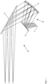
- Fig. 2 shows schematically a head-up display 10 with a horizontally arranged direction-selective reflector 150.
- the example shown is again a head-up display 10 for a motor vehicle, with an imaging unit 11 for generating an image and an optical system 12 for projecting the image onto a projection surface 21.
- the optical system 12 has a first mirror 13 and a second mirror 14.
- a direction-selective reflector 150 is arranged in the optical path between the first mirror 13 and the second mirror 14 as a selectively reflecting element 15, which acts as a mirror for a certain angular range, for example in the range 40°-60°, and is transparent for other angular ranges , e.g. in the range 0°-25°.
- the direction-selective reflector 150 is arranged approximately horizontally, ie the reflecting surface of the direction-selective reflector 150 is arranged at an angle of less than 45° relative to the horizontal.
- the light emanating from the imaging unit 11 hits the direction-selective reflector 150 at small angles, it is not reflected by it and reaches the first mirror 13 unhindered.
- This is arranged in such a way that the light reflected by the first mirror 13 is reflected at significantly larger angles hits the direction-selective reflector 150 and is reflected by it in the direction of the second mirror 14.
- the second mirror 14 is now arranged in such a way that the light reflected by it hits the direction-selective reflector 150 at small angles and therefore reaches the projection surface 21 unhindered.
- the direction-selective reflector 150 is thus used to effect an additional folding of the beam path. At the same time, a blockage of the light paths is avoided.
- the additional folding of the beam path makes it possible to arrange the two mirrors 13, 14 next to each other, thereby achieving a volume reduction of the entire system.
- the two mirrors 13, 14 can be formed in one piece.
- the directional selectivity of the reflector 150 can be achieved through various solutions.
- a first solution uses a reflective volume grid. This can be produced, for example, as a film.
- the direction-selective reflector 150 is designed as a substrate with a multilayer thin-film coating.
- the imaging unit 11 can include at least one light source and a spatial light modulator.
- a spatial light modulator can be a TFT display (TFT: Thin Film Transistor), an OLED display (OLED: Organic Light Emitting Diode) or a micro-LED display (LED: Light Emitting Diode).
- TFT Thin Film Transistor
- OLED Organic Light Emitting Diode
- micro-LED LED: Light Emitting Diode
- a projected image from a transmissive or reflective display or the Fourier image from a phase display can also be used at this location.
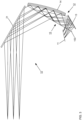
- Fig. 3 shows schematically a head-up display 10 with a vertically arranged direction-selective reflector 150.
- the structure of the head-up display 10 largely corresponds to that of the head-up display 10 Fig. 2 .
- the direction-selective reflector 150 as a selectively reflecting element 15 is arranged approximately vertically in this embodiment, that is, the reflecting surface of the direction-selective reflector 150 is arranged at an angle of less than 45° relative to the vertical. Tilting the direction-selective reflector 150 into an approximately vertical position is advantageous for avoiding disruptive reflections of sunlight.
- the direction-selective reflector 150 acts as a mirror for a certain angular range, for example in the range 40°-60°, while it is transparent for other angular ranges, for example in the range 0°-25°.
- the light emanating from the imaging unit 11 hits the direction-selective reflector 150 at small angles. It is therefore not reflected by it and reaches the first mirror 13 unhindered.
- This is arranged in such a way that the light reflected by the first mirror 13 hits the direction-selective reflector 150 at significantly larger angles and is reflected by it in the direction of the second mirror 14.
- the second mirror 14 is now again arranged so that the light reflected by it hits the direction-selective reflector 150 at smaller angles and therefore reaches the projection surface 21 unhindered. Due to the additional folding of the beam path caused by the direction-selective reflector 150, it is also possible here to arrange the two mirrors 13, 14 next to one another. In particular, the two mirrors 13, 14 can again be formed in one piece.
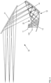
- Fig. 4 shows schematically a head-up display 10 with a curved direction-selective reflector 150 as a selectively reflecting element 15.
- the structure of the head-up display 10 largely corresponds to that of the head-up display 10 Fig. 2 .
- the direction-selective reflector 150 is curved in this embodiment.
- this curvature is cylindrical, for example for using materials that are produced as a film.
- a version with a more complex shape is also possible, for example as: Freeform mirror works.
- the direction-selective reflector 150 acts as a mirror for a certain angular range, for example in the range 40°-60°, while it is transparent for other angular ranges, for example in the range 0°-25°.
- the light emanating from the imaging unit 11 hits the direction-selective reflector 150 at small angles. It is therefore not reflected by it and reaches the first mirror 13 unhindered.
- this also has a curvature and is arranged in this way that the light reflected by the first mirror 13 hits the direction-selective reflector 150 at significantly larger angles and is reflected by it in the direction of the second mirror 14.
- the second mirror 14 is now arranged in such a way that the light reflected by it hits the direction-selective reflector 150 at smaller angles and thus reaches the projection surface 21 unhindered. Due to the additional folding of the beam path caused by the direction-selective reflector 150, it is also possible here to arrange the two mirrors 13, 14 next to one another. In particular, the two mirrors 13, 14 can again be formed in one piece.
- Fig. 5 shows schematically a head-up display 10 with a direction-selective reflector 150 as a selectively reflecting element 15 and additional lenses 17, 17'.
- the structure of the head-up display 10 largely corresponds to that of the head-up display 10 Fig. 2 .
- the direction-selective reflector 150 acts as a mirror for a certain angular range, for example in the range 40°-60°, while it is transparent for other angular ranges, for example in the range 0°-25°.
- the direction-selective reflector 150 provides additional optically active surfaces in the beam path, on which two additional lenses 17, 17' are arranged in this example. These can be used, for example, for additional aberration correction in the image.
- the light emanating from the imaging unit 11 hits the direction-selective reflector 150 at small angles. It is therefore not reflected by it and reaches the first mirror 13 unhindered.
- this also has a curvature and is arranged so that the light reflected by the first mirror 13 hits the direction-selective reflector 150 at significantly larger angles and is reflected by it in the direction of the second mirror 14.
- the second mirror 14 is now arranged in such a way that the light reflected by it hits the direction-selective reflector 150 at smaller angles and thus reaches the projection surface 21 unhindered.
- the direction-selective reflector 150 caused With additional folding of the beam path, it is also possible here to arrange the two mirrors 13, 14 next to each other. In particular, the two mirrors 13, 14 can again be formed in one piece.
- Fig. 6 shows schematically an exemplary structure of a direction-selective reflector 150.
- the direction-selective reflector 150 has a substrate 152 which is provided with a coating 153.
- the coating 153 can be, for example, a multilayer thin-film coating. This is designed in such a way that it is transparent for certain angular ranges for frequency bands and reflective for others.
- the layers of the coating 153 can be applied directly to the substrate 152, but the coating 153 can also be produced in the form of a film and then applied as a whole to the substrate 152.
- the substrate 152 is flat; alternatively, it can also have a curvature. If the coating 153 is to be applied as a film, this curvature is preferably cylindrical. However, a version with a more complex shape is also possible, which then acts as a free-form mirror, for example. In addition, it is in Fig. 6 a region of the substrate 152 is designed as a lens 154, for example for additional aberration correction.
- Fig. 7 shows schematically a head-up display 10 with a polarization-selective reflector 151.
- polarization selectivity is used instead of direction selectivity.
- the polarization-selective reflector 151 is designed, for example by a suitable coating, so that it is reflective for S-polarized light but transmits P-polarized light.
- the light emanating from the imaging unit 11 is P-polarized and can therefore pass through the polarization-selective reflector 151 unhindered. It passes through a quarter-wave plate 16 arranged in front of the first mirror 13, so that the light is circularly polarized.
- the circularly polarized light passes through the quarter-wave plate 16 again, so that it is now S-polarized. It is therefore subsequently reflected by the polarization-selective reflector 151 in the direction of the second mirror 14.
- a further quarter-wave plate 16' is arranged in front of the second mirror 14. After reflection on the second mirror 14 on the polarization-selective reflector 151, it is therefore P-polarized again and can pass through the polarization-selective reflector 151 unhindered in the direction of the projection surface 21.
- the polarization-selective reflector 151 must be adjusted accordingly. In this case it must be reflective for P-polarized light but transmit S-polarized light.
- Fig. 8 schematically represents a means of transport 20 in which a solution according to the invention is implemented.
- the means of transport 20 is a motor vehicle.
- the motor vehicle has a head-up display 10 according to the invention.
- the windshield of the motor vehicle serves as the projection surface 21.
- the display device 42 is preferably designed to be touch-sensitive.
- Further components of the motor vehicle are an assistance system 22, an environmental sensor system 23 for detecting environmental information, such as cameras, radar sensors, lidar sensors or ultrasonic sensors, and a data transmission unit 24.
- a connection to a backend can be established, for example for transmitting collected data Data or to obtain updated software for the components of the motor vehicle.
- a memory 25 is available to store data. The data exchange between the various components of the motor vehicle takes place via a network 26.
Abstract
Die vorliegende Erfindung betrifft ein Head-up-Display (10), insbesondere ein Head-up-Display (10) für ein Fortbewegungsmittel. Die Erfindung betrifft weiterhin ein Fortbewegungsmittel mit einem solchen Head-up-Display (10). Das Head-up-Display (10) weist eine bildgebende Einheit (11) zum Erzeugen eines Bildes und ein optisches System (12) zum Projizieren des Bildes auf eine Projektionsfläche (21) auf. Das optische System (12) weist zumindest einen ersten Spiegel (13), einen zweiten Spiegel (14) und ein selektiv reflektierendes Element (15) auf. Das selektiv reflektierende Element (15) ist im optischen Pfad zwischen dem ersten Spiegel (13) und dem zweiten Spiegel (14) angeordnet.

Description
Die vorliegende Erfindung betrifft ein Head-up-Display, insbesondere ein Head-up-Display für ein Fortbewegungsmittel. Die Erfindung betrifft weiterhin ein Fortbewegungsmittel mit einem solchen Head-up-Display.The present invention relates to a head-up display, in particular a head-up display for a means of transportation. The invention further relates to a means of transport with such a head-up display.
Mit der stetigen Weiterentwicklung von Virtual & Augmented Reality-Technologien und - Anwendungen finden diese auch Einzug in das Automobil. Bei Augmented Reality (AR), auf Deutsch "erweiterte Realität", handelt es sich um die Anreicherung der realen Welt durch virtuelle Elemente, die im dreidimensionalen Raum ortskorrekt registriert sind und eine Echtzeitinteraktion erlauben. Da sich in der Fachwelt im deutschsprachigen Raum der Ausdruck "Augmented Reality" gegenüber dem Ausdruck "erweiterte Realität" durchgesetzt hat, wird im Folgenden ersterer benutzt.With the constant development of virtual and augmented reality technologies and applications, they are also finding their way into the automobile. Augmented Reality (AR), or "extended reality" in German, is the enrichment of the real world with virtual elements that are correctly registered in three-dimensional space and allow real-time interaction. Since the term "augmented reality" has prevailed over the term "extended reality" in the professional world in German-speaking countries, the former will be used below.
Eine mögliche technische Realisierung, um den Fahrerarbeitsplatz mit virtuellen Erweiterungen anzureichern, bietet das Head-up-Display. Unter einem Head-up-Display, auch als HUD bezeichnet, wird ein Anzeigesystem verstanden, bei dem der Betrachter seine Blickrichtung beibehalten kann, da die darzustellenden Inhalte in sein Sichtfeld eingeblendet werden. Während derartige Systeme aufgrund ihrer Komplexität und Kosten ursprünglich vorwiegend im Bereich der Luftfahrt Verwendung fanden, werden sie inzwischen auch im Automobilbereich in Großserie verbaut.The head-up display offers a possible technical implementation for enriching the driver's workplace with virtual extensions. A head-up display, also known as a HUD, is a display system in which the viewer can maintain his line of sight because the content to be displayed is displayed in his field of vision. While such systems were originally used primarily in the aviation sector due to their complexity and cost, they are now also being installed in large series in the automotive sector.
Head-up-Displays bestehen im Allgemeinen aus einer bildgebenden Einheit bzw. PGU (Picture Generating Unit), einem optischen System und einer Projektionsfläche. Die bildgebende Einheit erzeugt das Bild und nutzt dazu zumindest ein Anzeigeelement. Das optische System projiziert das Bild auf die Projektionsfläche. Die Projektionsfläche ist eine teilweise spiegelnde, lichtdurchlässige Scheibe. Der Betrachter sieht also die von der bildgebenden Einheit dargestellten Inhalte als virtuelles Bild und gleichzeitig die reale Welt hinter der Scheibe. Als Projektionsfläche dient im Automobilbereich oftmals die Windschutzscheibe, deren gekrümmte Form bei der Darstellung berücksichtigt werden muss. Als Alternative wird zum Teil auch eine zusätzliche Scheibe aus Glas oder Kunststoff genutzt, die zwischen dem Fahrer und der Frontscheibe auf dem Armaturenbrett angeordnet ist. Durch das Zusammenwirken des optischen Systems und der Projektionsfläche ist das virtuelle Bild eine vergrößerte Darstellung des von der bildgebenden Einheit erzeugten Bildes. Durch die optische Überlagerung von Anzeige und Fahrszene sind weniger Kopf- und Augenbewegungen zum Ablesen der Informationen notwendig. Zudem verringert sich der Adaptationsaufwand für die Augen, da abhängig von der virtuellen Distanz der Anzeige weniger bis gar nicht akkommodiert werden muss.Head-up displays generally consist of an imaging unit or PGU (Picture Generating Unit), an optical system and a projection surface. The imaging unit generates the image and uses at least one display element for this purpose. The optical system projects the image onto the projection surface. The projection surface is a partially reflective, translucent disc. The viewer sees the content displayed by the imaging unit as a virtual image and at the same time the real world behind the window. In the automotive sector, the windshield is often used as a projection surface, and its curved shape must be taken into account in the display. As an alternative, an additional pane made of glass or plastic is sometimes used, which is arranged between the driver and the windshield on the dashboard. Through the interaction of the optical system and the projection surface, the virtual image is an enlarged representation of the image generated by the imaging unit. The visual overlay of the display and the driving scene means that fewer head and eye movements are necessary to read the information. In addition, the adaptation effort for the eyes is reduced because, depending on the virtual distance of the display, there is less or no need for accommodation.
Das optische System eines Head-up-Displays umfasst, insbesondere bei einem AR-Head-up-Display oder einem 3D-Head-up-Display, in der Regel zwei gegenüberliegend angeordnete Spiegel zur Faltung des Strahlengangs.The optical system of a head-up display, in particular in the case of an AR head-up display or a 3D head-up display, usually includes two oppositely arranged mirrors for folding the beam path.
Beispielsweise beschreibt
Bei der bekannten Ausgestaltung müssen die Spiegel ausreichend weit voneinander entfernt stehen, damit sie nicht die Lichtwege zur Projektionsfläche und vom der bildgebenden Einheit zum jeweils anderen Spiegel blockieren. Dies führt zu einem großen Volumen der gesamten Einheit.In the known design, the mirrors must be sufficiently far apart from each other so that they do not block the light paths to the projection surface and from the imaging unit to the other mirror. This results in a large volume of the entire unit.
Es ist eine Aufgabe der Erfindung, Lösungen für die Realisierung eines Head-up-Displays mit einem reduzierten Bauraum bereitzustellen.It is an object of the invention to provide solutions for the realization of a head-up display with a reduced installation space.
Diese Aufgabe wird durch ein Head-up-Display mit den Merkmalen des Anspruchs 1 sowie durch ein Fortbewegungsmittel gemäß Anspruch 15 gelöst. Bevorzugte Ausgestaltungen der Erfindung sind Gegenstand der abhängigen Ansprüche.This task is achieved by a head-up display with the features of claim 1 and by a means of transport according to
Gemäß einem ersten Aspekt der Erfindung weist ein Head-up-Display eine bildgebende Einheit zum Erzeugen eines Bildes und ein optisches System zum Projizieren des Bildes auf eine Projektionsfläche auf. Das optische System weist zumindest einen ersten Spiegel, einen zweiten Spiegel und ein selektiv reflektierendes Element auf. Das selektiv reflektierende Element ist im optischen Pfad zwischen dem ersten Spiegel und dem zweiten Spiegel angeordnet.According to a first aspect of the invention, a head-up display has an imaging unit for generating an image and an optical system for projecting the image onto a projection surface. The optical system has at least a first mirror, a second mirror and a selectively reflecting element. The selectively reflective Element is arranged in the optical path between the first mirror and the second mirror.
Bei der erfindungsgemäßen Lösung wird ein selektiv reflektierendes Element genutzt, um eine zusätzliche Faltung des Strahlengangs zu bewirken. Dies ermöglicht eine Volumenreduktion des Gesamtsystems. Das selektiv reflektierende Element ist dabei derart ausgestaltet, dass es vom Licht auf dem Weg von der bildgebenden Einheit zum ersten Spiegel und auf dem Weg vom zweiten Spiegel zur Projektionsfläche ungehindert durchlaufen werden kann. Auf diese Weise wird eine Blockade der Lichtwege vermieden. Zugleich werden vom selektiv reflektierenden Element zusätzliche optisch aktive Flächen an Orten im Strahlengang zur Verfügung gestellt, wo diese ohne das selektiv reflektierende Element nicht positionierbar waren, da sie im Strahlengang zwischen anderen Flächen zu Verschattungen führen würden.In the solution according to the invention, a selectively reflecting element is used to bring about an additional folding of the beam path. This enables a volume reduction of the entire system. The selectively reflecting element is designed in such a way that light can pass through it unhindered on the way from the imaging unit to the first mirror and on the way from the second mirror to the projection surface. In this way, blockage of the light paths is avoided. At the same time, the selectively reflecting element provides additional optically active surfaces at locations in the beam path where these could not be positioned without the selectively reflecting element because they would lead to shading between other surfaces in the beam path.
Gemäß einem Aspekt der Erfindung ist das selektiv reflektierende Element ein richtungsselektiver Reflektor, der für einen bestimmten Winkelbereich als Spiegel wirkt und für andere Winkelbereiche transparent ist. Vorzugsweise wirkt der richtungsselektive Reflektor zumindest im Bereich 40°-60° als Spiegel und ist zumindest im Bereich 0°-25° transparent. Indem das von der bildgebenden Einheit ausgehende Licht unter einem kleinen Winkel auf das selektiv reflektierende Element trifft, wird es von diesem nicht reflektiert und gelangt ungehindert zum ersten Spiegel. Dieser ist so angeordnet, dass das vom ersten Spiegel reflektierte Licht unter einem deutlich größeren Winkel auf das selektiv reflektierende Element trifft und von diesem in Richtung des zweiten Spiegels reflektiert wird. Der zweite Spiegel ist nun wiederum so angeordnet, dass das von ihm reflektierte Licht unter einem kleinen Winkel auf das selektiv reflektierende Element trifft und daher ungehindert zur Projektionsfläche gelangt.According to one aspect of the invention, the selectively reflecting element is a direction-selective reflector that acts as a mirror for a certain angular range and is transparent for other angular ranges. Preferably, the direction-selective reflector acts as a mirror at least in the range 40°-60° and is transparent at least in the range 0°-25°. Because the light emanating from the imaging unit hits the selectively reflecting element at a small angle, it is not reflected by it and reaches the first mirror unhindered. This is arranged in such a way that the light reflected by the first mirror hits the selectively reflecting element at a significantly larger angle and is reflected by it in the direction of the second mirror. The second mirror is now arranged in such a way that the light reflected by it hits the selectively reflecting element at a small angle and therefore reaches the projection surface unhindered.
Gemäß einem Aspekt der Erfindung ist der richtungsselektive Reflektor als reflektives Volumengitter ausgestaltet. Die Richtungsselektivität des Reflektors kann durch verschiedene Lösungen erreicht werden. Bei einer ersten Lösung wird ein reflektives Volumengitter genutzt. Ein solches kann beispielsweise als Folie hergestellt werden, was die Handhabung vereinfacht. Ist das Volumengitter symmetrisch, d.h. sind Einfallswinkel und Ausfallswinkel gleich, weist das Gitter keine Dispersion auf. Dies wirkt sich vorteilhaft auf die Auswahl geeigneter Lichtquellen aus.According to one aspect of the invention, the direction-selective reflector is designed as a reflective volume grid. The directional selectivity of the reflector can be achieved through various solutions. A first solution uses a reflective volume grid. This can be made, for example, as a film, which simplifies handling. If the volume grating is symmetrical, i.e. the angle of incidence and angle of reflection are the same, the grating has no dispersion. This has an advantageous effect on the selection of suitable light sources.
Gemäß einem Aspekt der Erfindung weist das reflektive Volumengitter eine zusätzliche optische Funktion auf. Beispielsweise kann das reflektive Volumengitter eine Linsenfunktion aufweisen. Durch die Kombination der Eigenschaft des reflektiven Volumengitters, den Strahlengang zu fakten, mit einer weiteren optischen Funktion, kann ein eventuell erforderliches weiteres optisches Element im Strahlengang eingespart werden. Beispielsweise erlaubt die Linsenfunktion eine zusätzliche Aberrationskorrektur in der Abbildung.According to one aspect of the invention, the reflective volume grating has an additional optical function. For example, the reflective volume grid can have a lens function. By combining the properties of the reflective volume grid, the beam path Facts, with an additional optical function, any additional optical element that may be required can be saved in the beam path. For example, the lens function allows additional aberration correction in the image.
Gemäß einem Aspekt der Erfindung ist der richtungsselektive Reflektor als Substrat mit einer Multilayer-Dünnschichtbeschichtung ausgestaltet. Bei einer zweiten Lösung für das Erreichen der Richtungsselektivität des Reflektors wird eine interferenzbasierte Beschichtung genutzt. Diese ist derart ausgestaltet, dass sie für Frequenzbänder für bestimmte Winkelbereiche transparent und für andere reflektiv ist. Die Verwendung von Dünnschichtbeschichtungen hat den Vorteil, dass sich diese sehr exakt mit gewünschten Eigenschaften herstellen lassen.According to one aspect of the invention, the direction-selective reflector is designed as a substrate with a multilayer thin-film coating. A second solution for achieving directional selectivity of the reflector uses an interference-based coating. This is designed in such a way that it is transparent for certain angular ranges for frequency bands and reflective for others. The advantage of using thin-film coatings is that they can be produced very precisely with the desired properties.
Gemäß einem Aspekt der Erfindung ist zumindest ein Bereich des Substrats als Linse ausgestaltet. Das Substrat, auf dem sich die Dünnschichtbeschichtung befindet, kann selbst als refraktive Linse ausgeführt werden, z.B. für eine zusätzliche Aberrationskorrektur. Dabei kann die spiegelnde Seite plan oder zylindrisch bleiben, um z.B. Beschichtungen auf Folie aufzunehmen.According to one aspect of the invention, at least a region of the substrate is designed as a lens. The substrate on which the thin-film coating is located can itself be designed as a refractive lens, e.g. for additional aberration correction. The reflective side can remain flat or cylindrical, for example to accommodate coatings on foil.
Gemäß einem Aspekt der Erfindung ist das selektiv reflektierende Element ein polarisationsselektiver Reflektor. Vor dem ersten Spiegel und vor dem zweiten Spiegel ist in diesem Falls vorzugsweise jeweils eine Viertelwellenplatte angeordnet. Beispielsweise kann das das selektiv reflektierende Element eine Beschichtung aufweisen, die für S-polarisiertes Licht reflektiv ist, aber P-polarisiertes Licht transmittiert. Ergänzend ist dann sowohl vor dem ersten Spiegel als auch vor dem zweiten Spiegel eine Viertelwellenplatte positioniert, um mittels des doppelten Durchgangs durch die Viertelwellenplatte die Polarisation des Lichts auf dem Weg zu drehen.According to one aspect of the invention, the selectively reflective element is a polarization-selective reflector. In this case, a quarter-wave plate is preferably arranged in front of the first mirror and in front of the second mirror. For example, the selectively reflective element may have a coating that is reflective for S-polarized light but transmits P-polarized light. In addition, a quarter-wave plate is then positioned in front of both the first mirror and the second mirror in order to rotate the polarization of the light on the way by means of the double passage through the quarter-wave plate.
Gemäß einem Aspekt der Erfindung sind der erste Spiegel und der zweite Spiegel nebeneinander angeordnet. Dadurch, dass das selektiv reflektierende Element eine zusätzliche Faltung des Strahlengangs bewirkt, lassen sich die beiden Spiegel nebeneinander anordnen. Das Volumen des Systems kann durch diese Anordnung weiter reduziert werden.According to one aspect of the invention, the first mirror and the second mirror are arranged next to one another. Because the selectively reflecting element causes an additional folding of the beam path, the two mirrors can be arranged next to each other. The volume of the system can be further reduced by this arrangement.
Gemäß einem Aspekt der Erfindung sind der erste Spiegel und der zweite Spiegel einstückig gebildet. Dadurch, dass sich die beiden Spiegel nebeneinander anordnen lassen, besteht die Möglichkeit, die beide Spiegel in einem Stück zu produzieren. Typischerweise handelt es sich bei den Spiegeln um Freiformspiegel. Durch die einstückige Ausgestaltung wird einerseits ein Produktionsschritt eingespart, andererseits entfällt auch der Justageaufwand für die relative Ausrichtung der Spiegel bei der Montage des Gesamtsystems.According to one aspect of the invention, the first mirror and the second mirror are formed in one piece. Because the two mirrors can be arranged next to each other, it is possible to produce both mirrors in one piece. Typically the mirrors are free-form mirrors. Due to the one-piece design, on the one hand Production step is saved, and on the other hand, the adjustment effort for the relative alignment of the mirrors when assembling the entire system is also eliminated.
Gemäß einem Aspekt der Erfindung ist das selektiv reflektierende Element annähernd vertikal ausgerichtet. Unter einer annähernd vertikalen Ausrichtung ist dabei zu verstehen, dass die reflektierende Fläche unter einem Winkel von weniger als 45° relativ zur Vertikalen abgeordnet ist. Die Kippung des selektiv reflektierenden Elements in eine annähernd vertikale Position ist vorteilhaft zur Vermeidung von störenden Reflexionen von Sonnenlicht.According to one aspect of the invention, the selectively reflective element is oriented approximately vertically. An approximately vertical orientation means that the reflecting surface is positioned at an angle of less than 45° relative to the vertical. Tilting the selectively reflecting element into an approximately vertical position is advantageous for avoiding disruptive reflections of sunlight.
Gemäß einem Aspekt der Erfindung ist das selektiv reflektierende Element gekrümmt. Das selektiv reflektierende Element kann einerseits plan ausgeführt sein, aber es kann alternativ auch eine Krümmung aufweisen. Bei Materialien, die als Folie hergestellt werden, ist diese Krümmung bevorzugt zylindrisch. Es ist aber auch eine Ausführung mit komplexerer Formgebung möglich, die dann z.B. als Freiformspiegel wirkt.According to one aspect of the invention, the selectively reflective element is curved. On the one hand, the selectively reflecting element can be designed to be flat, but alternatively it can also have a curvature. For materials that are produced as a film, this curvature is preferably cylindrical. However, a version with a more complex shape is also possible, which then acts as a free-form mirror, for example.
Gemäß einem Aspekt der Erfindung ist benachbart zum selektiv reflektierenden Element zumindest eine zusätzliche Linse angeordnet. Auf dem bzw. nah bei dem Reflektor kann eine separate Linse positioniert werden, z.B. für eine zusätzliche Aberrationskorrektur in der Abbildung. Dies wäre im ungefalteten System ohne das selektiv reflektierende Element an diesem Ort nicht möglich, da die Linse einen anderen Strahlweg beeinflussen würde.According to one aspect of the invention, at least one additional lens is arranged adjacent to the selectively reflecting element. A separate lens can be positioned on or close to the reflector, e.g. for additional aberration correction in the image. This would not be possible in the unfolded system without the selectively reflecting element at this location because the lens would influence a different beam path.
Besonders vorteilhaft wird ein erfindungsgemäßes Head-up-Display in einem Fortbewegungsmittel eingesetzt. Bei dem Fortbewegungsmittel kann es sich beispielsweise um ein Kraftfahrzeug handeln, z.B. einen Personenkraftwagen oder ein Nutzfahrzeug. Die Nutzung der erfindungsgemäßen Lösung hat dabei den Vorteil, dass das Head-up-Display mit einem reduzierten Bauraum auskommt und daher die Anordnung im Fortbewegungsmittel vereinfacht wird.A head-up display according to the invention is particularly advantageously used in a means of transportation. The means of transport can be, for example, a motor vehicle, e.g. a passenger car or a commercial vehicle. The use of the solution according to the invention has the advantage that the head-up display requires a reduced installation space and therefore the arrangement in the means of transport is simplified.
Weitere Merkmale der vorliegenden Erfindung werden aus der nachfolgenden Beschreibung und den angehängten Ansprüchen in Verbindung mit den Figuren ersichtlich.
- Fig. 1
- zeigt schematisch ein Head-up-Display gemäß dem Stand der Technik;
- Fig. 2
- zeigt schematisch ein Head-up-Display mit einem horizontal angeordneten richtungsselektiven Reflektor;
- Fig. 3
- zeigt schematisch ein Head-up-Display mit einem vertikal angeordneten richtungsselektiven Reflektor;
- Fig. 4
- zeigt schematisch ein Head-up-Display mit einem gekrümmten richtungsselektiven Reflektor;
- Fig. 5
- zeigt schematisch ein Head-up-Display mit einem richtungsselektiven Reflektor und zusätzlichen Linsen;
- Fig. 6
- zeigt schematisch einen beispielhaften Aufbau eines richtungsselektiven Reflektors;
- Fig. 7
- zeigt schematisch ein Head-up-Display mit einem polarisationsselektiven Reflektor; und
- Fig. 8
- stellt schematisch ein Fortbewegungsmittel dar, in dem eine erfindungsgemäße Lösung realisiert ist.
- Fig. 1
- shows schematically a head-up display according to the prior art;
- Fig. 2
- shows schematically a head-up display with a horizontally arranged direction-selective reflector;
- Fig. 3
- shows schematically a head-up display with a vertically arranged direction-selective reflector;
- Fig. 4
- shows schematically a head-up display with a curved direction-selective reflector;
- Fig. 5
- shows schematically a head-up display with a direction-selective reflector and additional lenses;
- Fig. 6
- shows schematically an exemplary structure of a direction-selective reflector;
- Fig. 7
- shows schematically a head-up display with a polarization-selective reflector; and
- Fig. 8
- schematically represents a means of transport in which a solution according to the invention is implemented.
Zum besseren Verständnis der Prinzipien der vorliegenden Erfindung werden nachfolgend Ausführungsformen der Erfindung anhand der Figuren detaillierter erläutert. Es versteht sich, dass sich die Erfindung nicht auf diese Ausführungsformen beschränkt und dass die beschriebenen Merkmale auch kombiniert oder modifiziert werden können, ohne den Schutzbereich der Erfindung zu verlassen, wie er in den angehängten Ansprüchen definiert ist.For a better understanding of the principles of the present invention, embodiments of the invention are explained in more detail below with reference to the figures. It is understood that the invention is not limited to these embodiments and that the described features can also be combined or modified without departing from the scope of the invention as defined in the appended claims.
Indem das von der bildgebenden Einheit 11 ausgehende Licht unter kleinen Winkeln auf den richtungsselektiven Reflektor 150 trifft, wird es von diesem nicht reflektiert und gelangt ungehindert zum ersten Spiegel 13. Dieser ist so angeordnet, dass das vom ersten Spiegel 13 reflektierte Licht unter deutlich größeren Winkeln auf den richtungsselektiven Reflektor 150 trifft und von diesem in Richtung des zweiten Spiegels 14 reflektiert wird. Der zweite Spiegel 14 ist nun wiederum so angeordnet, dass das von ihm reflektierte Licht unter kleinen Winkeln auf den richtungsselektiven Reflektor 150 trifft und daher ungehindert zur Projektionsfläche 21 gelangt.Because the light emanating from the
Der richtungsselektive Reflektor 150 wird somit genutzt, um eine zusätzliche Faltung des Strahlengangs zu bewirken. Zugleich wird eine Blockade der Lichtwege vermieden. Durch die zusätzliche Faltung des Strahlengangs ist es möglich, die beiden Spiegel 13, 14 nebeneinander anzuordnen, wodurch eine Volumenreduktion des Gesamtsystems erreicht wird. Insbesondere können die beiden Spiegel 13, 14 einstückig gebildet sein.The direction-
Die Richtungsselektivität des Reflektors 150 kann durch verschiedene Lösungen erreicht werden. Bei einer ersten Lösung wird ein reflektives Volumengitter genutzt. Ein solches kann beispielsweise als Folie hergestellt werden. Bei einer zweiten Lösung ist der richtungsselektive Reflektor 150 als Substrat mit einer Multilayer-Dünnschichtbeschichtung ausgestaltet.The directional selectivity of the
Die bildgebende Einheit 11 kann zumindest eine Lichtquelle und einen räumlichen Lichtmodulator umfassen. Beispielsweise kann es sich um ein TFT-Display handeln (TFT: Thin Film Transistor; Dünnschichttransistor), um ein OLED-Display (OLED: Organic Light Emitting Diode; Organische Leuchtdiode) oder ein Micro-LED Display (LED: Light Emitting Diode; Leuchtdiode). Auch kann an diesem Ort ein projiziertes Bild aus einem transmissivem oder reflektivem Display oder das Fourier Bild aus einem Phasendisplay genutzt werden.The
Auch bei dieser Ausführungsform trifft das von der bildgebenden Einheit 11 ausgehende Licht unter kleinen Winkeln auf den richtungsselektiven Reflektor 150. Es wird daher von diesem nicht reflektiert und gelangt ungehindert zum ersten Spiegel 13. Dieser ist so angeordnet, dass das vom ersten Spiegel 13 reflektierte Licht unter deutlich größeren Winkeln auf den richtungsselektiven Reflektor 150 trifft und von diesem in Richtung des zweiten Spiegels 14 reflektiert wird. Der zweite Spiegel 14 ist nun wiederum so angeordnet, dass das von ihm reflektierte Licht unter kleineren Winkeln auf den richtungsselektiven Reflektor 150 trifft und daher ungehindert zur Projektionsfläche 21 gelangt. Durch die vom richtungsselektiven Reflektor 150 bewirkte zusätzliche Faltung des Strahlengangs ist es auch hier möglich, die beiden Spiegel 13, 14 nebeneinander anzuordnen. Insbesondere können die beiden Spiegel 13, 14 wiederum einstückig gebildet sein.In this embodiment too, the light emanating from the
Auch bei dieser Ausführungsform trifft das von der bildgebenden Einheit 11 ausgehende Licht unter kleinen Winkeln auf den richtungsselektiven Reflektor 150. Es wird daher von diesem nicht reflektiert und gelangt ungehindert zum ersten Spiegel 13. Dieser weist bei dieser Ausführungsform ebenfalls eine Krümmung auf und ist so angeordnet, dass das vom ersten Spiegel 13 reflektierte Licht unter deutlich größeren Winkeln auf den richtungsselektiven Reflektor 150 trifft und von diesem in Richtung des zweiten Spiegels 14 reflektiert wird. Der zweite Spiegel 14 ist nun wiederum so angeordnet, dass das von ihm reflektierte Licht unter kleineren Winkeln auf den richtungsselektiven Reflektor 150 trifft und somit ungehindert zur Projektionsfläche 21 gelangt. Durch die vom richtungsselektiven Reflektor 150 bewirkte zusätzliche Faltung des Strahlengangs ist es auch hier möglich, die beiden Spiegel 13, 14 nebeneinander anzuordnen. Insbesondere können die beiden Spiegel 13, 14 wiederum einstückig gebildet sein.In this embodiment, too, the light emanating from the
Wie auch bei den vorherigen Ausführungsformen trifft das von der bildgebenden Einheit 11 ausgehende Licht unter kleinen Winkeln auf den richtungsselektiven Reflektor 150. Es wird daher von diesem nicht reflektiert und gelangt ungehindert zum ersten Spiegel 13. Dieser weist im gezeigten Beispiel ebenfalls eine Krümmung auf und ist so angeordnet, dass das vom ersten Spiegel 13 reflektierte Licht unter deutlich größeren Winkeln auf den richtungsselektiven Reflektor 150 trifft und von diesem in Richtung des zweiten Spiegels 14 reflektiert wird. Der zweite Spiegel 14 ist nun wiederum so angeordnet, dass das von ihm reflektierte Licht unter kleineren Winkeln auf den richtungsselektiven Reflektor 150 trifft und somit ungehindert zur Projektionsfläche 21 gelangt. Durch die vom richtungsselektiven Reflektor 150 bewirkte zusätzliche Faltung des Strahlengangs ist es auch hier möglich, die beiden Spiegel 13, 14 nebeneinander anzuordnen. Insbesondere können die beiden Spiegel 13, 14 wiederum einstückig gebildet sein.As in the previous embodiments, the light emanating from the
Im dargestellten Beispiel ist das Substrat 152 plan, es kann alternativ auch eine Krümmung aufweisen. Falls die Beschichtung 153 als Folie aufgebracht werden soll, ist diese Krümmung bevorzugt zylindrisch. Es ist aber auch eine Ausführung mit komplexerer Formgebung möglich, die dann z.B. als Freiformspiegel wirkt. Zudem ist in
Sollte die bildgebende Einheit 11 S-polarisiertes Licht abstrahlen, muss der polarisationsselektive Reflektor 151 entsprechend angepasst werden. In diesem Fall muss er für P-polarisiertes Licht reflektiv sein, aber S-polarisiertes Licht transmittieren.Should the
- 1010
- Head-up-DisplayHead-Up Display
- 1111
- Bildgebende EinheitImaging unit
- 1212
- Optisches SystemOptical system
- 1313
- Erster SpiegelFirst mirror
- 1414
- Zweiter SpiegelSecond mirror
- 1515
- Selektiv reflektierendes ElementSelectively reflective element
- 16, 16`16, 16`
- ViertelwellenplatteQuarter wave plate
- 17, 17`17, 17`
- Linselens
- 2020
- FortbewegungsmittelMeans of transportation
- 2121
- ProjektionsflächeProjection surface
- 2222
- AssistenzsystemAssistance system
- 2323
- UmgebungssensorikEnvironmental sensors
- 2424
- DatenübertragungseinheitData transmission unit
- 2525
- SpeicherStorage
- 2626
- Netzwerknetwork
- 150150
- Richtungsselektiver ReflektorDirectionally selective reflector
- 151151
- Polarisationsselektiver ReflektorPolarization selective reflector
- 152152
- SubstratSubstrate
- 153153
- BeschichtungCoating
- 154154
- Linselens
Claims (14)
Applications Claiming Priority (1)
| Application Number | Priority Date | Filing Date | Title |
|---|---|---|---|
| DE102022206293.0A DE102022206293A1 (en) | 2022-06-23 | 2022-06-23 | Head-up display and means of transportation with a head-up display |
Publications (1)
| Publication Number | Publication Date |
|---|---|
| EP4300166A1 true EP4300166A1 (en) | 2024-01-03 |
Family
ID=86604023
Family Applications (1)
| Application Number | Title | Priority Date | Filing Date |
|---|---|---|---|
| EP23175053.0A Pending EP4300166A1 (en) | 2022-06-23 | 2023-05-24 | Head-up display and means of locomotion having a head-up display |
Country Status (3)
| Country | Link |
|---|---|
| EP (1) | EP4300166A1 (en) |
| CN (1) | CN117289456A (en) |
| DE (1) | DE102022206293A1 (en) |
Citations (5)
| Publication number | Priority date | Publication date | Assignee | Title |
|---|---|---|---|---|
| DE102011075884A1 (en) * | 2011-05-16 | 2012-11-22 | Robert Bosch Gmbh | HUD with holographic optical elements |
| US20170235136A1 (en) * | 2016-02-12 | 2017-08-17 | Lg Electronics Inc. | Head up display for vehicle |
| US20170336628A1 (en) * | 2016-05-23 | 2017-11-23 | Lg Electronics Inc. | Head up display for vehicle |
| WO2019087615A1 (en) * | 2017-10-30 | 2019-05-09 | 株式会社デンソー | Virtual image display device |
| US20200026073A1 (en) | 2016-09-22 | 2020-01-23 | Denso Corporation | Head-up display device |
-
2022
- 2022-06-23 DE DE102022206293.0A patent/DE102022206293A1/en active Pending
-
2023
- 2023-05-24 EP EP23175053.0A patent/EP4300166A1/en active Pending
- 2023-06-19 CN CN202310726036.7A patent/CN117289456A/en active Pending
Patent Citations (5)
| Publication number | Priority date | Publication date | Assignee | Title |
|---|---|---|---|---|
| DE102011075884A1 (en) * | 2011-05-16 | 2012-11-22 | Robert Bosch Gmbh | HUD with holographic optical elements |
| US20170235136A1 (en) * | 2016-02-12 | 2017-08-17 | Lg Electronics Inc. | Head up display for vehicle |
| US20170336628A1 (en) * | 2016-05-23 | 2017-11-23 | Lg Electronics Inc. | Head up display for vehicle |
| US20200026073A1 (en) | 2016-09-22 | 2020-01-23 | Denso Corporation | Head-up display device |
| WO2019087615A1 (en) * | 2017-10-30 | 2019-05-09 | 株式会社デンソー | Virtual image display device |
Also Published As
| Publication number | Publication date |
|---|---|
| DE102022206293A1 (en) | 2023-12-28 |
| US20230415576A1 (en) | 2023-12-28 |
| CN117289456A (en) | 2023-12-26 |
Similar Documents
| Publication | Publication Date | Title |
|---|---|---|
| DE112017006376B4 (en) | FIELD OF VIEW DISPLAY DEVICE | |
| DE102016111783B4 (en) | Display device for superimposing a virtual image in the field of view of a user | |
| EP2894509A1 (en) | Field of vision display for a vehicle for displaying image information in two independent images to a viewer | |
| DE112014003685T5 (en) | Information display device | |
| DE112017006990B4 (en) | HEAD-UP DISPLAY DEVICE | |
| DE3712663A1 (en) | DISPLAY SYSTEM FOR ACCOMMODATION-FREE READING OF INFORMATION WITH EYE ADJUSTED | |
| DE102018215185B3 (en) | Method, apparatus and computer-readable storage medium with instructions for setting a head-up display in a motor vehicle, adjusting device for use in such a method or with such a device | |
| DE102011075884A1 (en) | HUD with holographic optical elements | |
| DE102007001266A1 (en) | Optical system for a head-up display installed in a motor vehicle has an image-generating device, image-mixing device, a beam splitter and an image-evaluating device | |
| WO2014023658A2 (en) | Head-up display | |
| DE102018203292A1 (en) | Display image projection system | |
| DE102010002956A1 (en) | Head-up display for vehicles, particularly for use as display area for displaying information by imaging unit of lucent surface in vehicle, has imaging lens that is arranged between imaging unit and display area | |
| DE102014211339A1 (en) | Head-up display with polarization-selective optical paths | |
| WO2019238846A1 (en) | Head-up display for a vehicle | |
| DE102008044334A1 (en) | Projection device and method for projection | |
| DE102009002189A1 (en) | Head-up display for displaying information to driver of vehicle e.g. car, has reflecting surface formed between reflection polarization foil and light source, and reflecting light reflected from polarization foil to light valve | |
| DE102018201769A1 (en) | A method, apparatus and computer readable storage medium having instructions for controlling a display of an augmented reality head-up display device for a motor vehicle | |
| DE102016111119A1 (en) | Laser projection device and method for generating virtual images | |
| EP4300166A1 (en) | Head-up display and means of locomotion having a head-up display | |
| DE102016005200A1 (en) | Head-up display device with a holographic optical element for a motor vehicle | |
| DE102021113845A1 (en) | Vehicle-side display device | |
| DE102019208649B3 (en) | Control of a display of an augmented reality head-up display device for a motor vehicle | |
| DE102016223381A1 (en) | Display device and visual field display system for a motor vehicle and method for operating such | |
| DE102010062634A1 (en) | Head-up display comprises projection unit for vehicle, where image forming unit is provided for emitting rays of image which is displayed, where optical elements comprises two mirrors | |
| DE102019000208B3 (en) | Display device of a motor vehicle, dashboard and motor vehicle |
Legal Events
| Date | Code | Title | Description |
|---|---|---|---|
| PUAI | Public reference made under article 153(3) epc to a published international application that has entered the european phase |
Free format text: ORIGINAL CODE: 0009012 |
|
| STAA | Information on the status of an ep patent application or granted ep patent |
Free format text: STATUS: REQUEST FOR EXAMINATION WAS MADE |
|
| STAA | Information on the status of an ep patent application or granted ep patent |
Free format text: STATUS: EXAMINATION IS IN PROGRESS |
|
| 17P | Request for examination filed |
Effective date: 20230524 |
|
| AK | Designated contracting states |
Kind code of ref document: A1 Designated state(s): AL AT BE BG CH CY CZ DE DK EE ES FI FR GB GR HR HU IE IS IT LI LT LU LV MC ME MK MT NL NO PL PT RO RS SE SI SK SM TR |
|
| 17Q | First examination report despatched |
Effective date: 20231215 |