JP5930231B2 - Projection device and head-up display device - Google Patents
Projection device and head-up display device Download PDFInfo
- Publication number
- JP5930231B2 JP5930231B2 JP2014167780A JP2014167780A JP5930231B2 JP 5930231 B2 JP5930231 B2 JP 5930231B2 JP 2014167780 A JP2014167780 A JP 2014167780A JP 2014167780 A JP2014167780 A JP 2014167780A JP 5930231 B2 JP5930231 B2 JP 5930231B2
- Authority
- JP
- Japan
- Prior art keywords
- projection light
- projection
- screen
- display
- imaging
- Prior art date
- Legal status (The legal status is an assumption and is not a legal conclusion. Google has not performed a legal analysis and makes no representation as to the accuracy of the status listed.)
- Active
Links
- 238000003384 imaging method Methods 0.000 claims description 57
- 230000003287 optical effect Effects 0.000 claims description 24
- 239000000758 substrate Substances 0.000 claims description 4
- 230000015572 biosynthetic process Effects 0.000 claims description 3
- 239000000463 material Substances 0.000 description 13
- 239000010408 film Substances 0.000 description 6
- 239000011521 glass Substances 0.000 description 5
- 229920003002 synthetic resin Polymers 0.000 description 5
- 239000000057 synthetic resin Substances 0.000 description 5
- 238000007740 vapor deposition Methods 0.000 description 4
- 238000012986 modification Methods 0.000 description 3
- 230000004048 modification Effects 0.000 description 3
- 238000009792 diffusion process Methods 0.000 description 2
- 239000004973 liquid crystal related substance Substances 0.000 description 2
- 238000004519 manufacturing process Methods 0.000 description 2
- 230000000007 visual effect Effects 0.000 description 2
- 230000005540 biological transmission Effects 0.000 description 1
- 238000012217 deletion Methods 0.000 description 1
- 230000037430 deletion Effects 0.000 description 1
- 230000001678 irradiating effect Effects 0.000 description 1
- 229910052710 silicon Inorganic materials 0.000 description 1
- 239000010703 silicon Substances 0.000 description 1
- 239000010409 thin film Substances 0.000 description 1
Images


Classifications
-
- G—PHYSICS
- G02—OPTICS
- G02B—OPTICAL ELEMENTS, SYSTEMS OR APPARATUS
- G02B27/00—Optical systems or apparatus not provided for by any of the groups G02B1/00 - G02B26/00, G02B30/00
- G02B27/01—Head-up displays
- G02B27/0101—Head-up displays characterised by optical features
-
- B—PERFORMING OPERATIONS; TRANSPORTING
- B60—VEHICLES IN GENERAL
- B60K—ARRANGEMENT OR MOUNTING OF PROPULSION UNITS OR OF TRANSMISSIONS IN VEHICLES; ARRANGEMENT OR MOUNTING OF PLURAL DIVERSE PRIME-MOVERS IN VEHICLES; AUXILIARY DRIVES FOR VEHICLES; INSTRUMENTATION OR DASHBOARDS FOR VEHICLES; ARRANGEMENTS IN CONNECTION WITH COOLING, AIR INTAKE, GAS EXHAUST OR FUEL SUPPLY OF PROPULSION UNITS IN VEHICLES
- B60K35/00—Instruments specially adapted for vehicles; Arrangement of instruments in or on vehicles
- B60K35/20—Output arrangements, i.e. from vehicle to user, associated with vehicle functions or specially adapted therefor
- B60K35/21—Output arrangements, i.e. from vehicle to user, associated with vehicle functions or specially adapted therefor using visual output, e.g. blinking lights or matrix displays
- B60K35/23—Head-up displays [HUD]
-
- G—PHYSICS
- G03—PHOTOGRAPHY; CINEMATOGRAPHY; ANALOGOUS TECHNIQUES USING WAVES OTHER THAN OPTICAL WAVES; ELECTROGRAPHY; HOLOGRAPHY
- G03B—APPARATUS OR ARRANGEMENTS FOR TAKING PHOTOGRAPHS OR FOR PROJECTING OR VIEWING THEM; APPARATUS OR ARRANGEMENTS EMPLOYING ANALOGOUS TECHNIQUES USING WAVES OTHER THAN OPTICAL WAVES; ACCESSORIES THEREFOR
- G03B21/00—Projectors or projection-type viewers; Accessories therefor
- G03B21/14—Details
- G03B21/28—Reflectors in projection beam
-
- H—ELECTRICITY
- H04—ELECTRIC COMMUNICATION TECHNIQUE
- H04N—PICTORIAL COMMUNICATION, e.g. TELEVISION
- H04N13/00—Stereoscopic video systems; Multi-view video systems; Details thereof
- H04N13/30—Image reproducers
-
- H—ELECTRICITY
- H04—ELECTRIC COMMUNICATION TECHNIQUE
- H04N—PICTORIAL COMMUNICATION, e.g. TELEVISION
- H04N9/00—Details of colour television systems
- H04N9/12—Picture reproducers
- H04N9/31—Projection devices for colour picture display, e.g. using electronic spatial light modulators [ESLM]
- H04N9/3141—Constructional details thereof
-
- B—PERFORMING OPERATIONS; TRANSPORTING
- B60—VEHICLES IN GENERAL
- B60K—ARRANGEMENT OR MOUNTING OF PROPULSION UNITS OR OF TRANSMISSIONS IN VEHICLES; ARRANGEMENT OR MOUNTING OF PLURAL DIVERSE PRIME-MOVERS IN VEHICLES; AUXILIARY DRIVES FOR VEHICLES; INSTRUMENTATION OR DASHBOARDS FOR VEHICLES; ARRANGEMENTS IN CONNECTION WITH COOLING, AIR INTAKE, GAS EXHAUST OR FUEL SUPPLY OF PROPULSION UNITS IN VEHICLES
- B60K2360/00—Indexing scheme associated with groups B60K35/00 or B60K37/00 relating to details of instruments or dashboards
- B60K2360/20—Optical features of instruments
- B60K2360/33—Illumination features
- B60K2360/334—Projection means
-
- B—PERFORMING OPERATIONS; TRANSPORTING
- B60—VEHICLES IN GENERAL
- B60K—ARRANGEMENT OR MOUNTING OF PROPULSION UNITS OR OF TRANSMISSIONS IN VEHICLES; ARRANGEMENT OR MOUNTING OF PLURAL DIVERSE PRIME-MOVERS IN VEHICLES; AUXILIARY DRIVES FOR VEHICLES; INSTRUMENTATION OR DASHBOARDS FOR VEHICLES; ARRANGEMENTS IN CONNECTION WITH COOLING, AIR INTAKE, GAS EXHAUST OR FUEL SUPPLY OF PROPULSION UNITS IN VEHICLES
- B60K2360/00—Indexing scheme associated with groups B60K35/00 or B60K37/00 relating to details of instruments or dashboards
- B60K2360/20—Optical features of instruments
- B60K2360/33—Illumination features
- B60K2360/343—Illumination of matrix displays
- B60K2360/344—Illumination of matrix displays for additionally illuminating mechanical elements, e.g. pointers or control knobs
-
- B—PERFORMING OPERATIONS; TRANSPORTING
- B60—VEHICLES IN GENERAL
- B60W—CONJOINT CONTROL OF VEHICLE SUB-UNITS OF DIFFERENT TYPE OR DIFFERENT FUNCTION; CONTROL SYSTEMS SPECIALLY ADAPTED FOR HYBRID VEHICLES; ROAD VEHICLE DRIVE CONTROL SYSTEMS FOR PURPOSES NOT RELATED TO THE CONTROL OF A PARTICULAR SUB-UNIT
- B60W50/00—Details of control systems for road vehicle drive control not related to the control of a particular sub-unit, e.g. process diagnostic or vehicle driver interfaces
- B60W50/08—Interaction between the driver and the control system
- B60W50/14—Means for informing the driver, warning the driver or prompting a driver intervention
- B60W2050/146—Display means
-
- G—PHYSICS
- G02—OPTICS
- G02B—OPTICAL ELEMENTS, SYSTEMS OR APPARATUS
- G02B27/00—Optical systems or apparatus not provided for by any of the groups G02B1/00 - G02B26/00, G02B30/00
- G02B27/01—Head-up displays
- G02B27/0179—Display position adjusting means not related to the information to be displayed
- G02B2027/0187—Display position adjusting means not related to the information to be displayed slaved to motion of at least a part of the body of the user, e.g. head, eye
-
- G—PHYSICS
- G02—OPTICS
- G02B—OPTICAL ELEMENTS, SYSTEMS OR APPARATUS
- G02B27/00—Optical systems or apparatus not provided for by any of the groups G02B1/00 - G02B26/00, G02B30/00
- G02B27/10—Beam splitting or combining systems
- G02B27/106—Beam splitting or combining systems for splitting or combining a plurality of identical beams or images, e.g. image replication
Landscapes
- Engineering & Computer Science (AREA)
- Physics & Mathematics (AREA)
- General Physics & Mathematics (AREA)
- Multimedia (AREA)
- Signal Processing (AREA)
- Chemical & Material Sciences (AREA)
- Combustion & Propulsion (AREA)
- Transportation (AREA)
- Mechanical Engineering (AREA)
- Optics & Photonics (AREA)
- Instrument Panels (AREA)
- Transforming Electric Information Into Light Information (AREA)
Description
本発明は、画像を所定箇所に投影する投影装置と、この投影装置が投影した画像を反射透過面に映して風景とともに画像を視認させるヘッドアップディスプレイ装置に関するものである。 The present invention relates to a projection device that projects an image on a predetermined location, and a head-up display device that projects an image projected by the projection device on a reflection / transmission surface and visually recognizes the image together with a landscape.
従来のヘッドアップディスプレイ装置は、例えば、特許文献1に開示されるものがある。このようなヘッドアップディスプレイ装置は、第1および第2の表示器とハーフミラーから構成されており、ハーフミラーにより透過光と反射光を重複して投影することで、ユーザに異なる表示距離の表示像(虚像)を視認させるものである。 A conventional head-up display device is disclosed in Patent Document 1, for example. Such a head-up display device is composed of first and second display devices and a half mirror. By projecting transmitted light and reflected light in duplicate by the half mirror, it is possible to display different display distances to the user. An image (virtual image) is visually recognized.
しかしながら、特許文献1に記載のヘッドアップディスプレイ装置は、複数の表示器を設けているため、ヘッドアップディスプレイ装置の容量が増大してしまったり、コストが上昇してしまったりするおそれがあった。また、ハーフミラーを用いているため、表示器から出射される表示光の利用効率が低下してしまうおそれがあった。 However, since the head-up display device described in Patent Document 1 is provided with a plurality of displays, the capacity of the head-up display device may increase or the cost may increase. Moreover, since the half mirror is used, there is a possibility that the utilization efficiency of the display light emitted from the display device may be reduced.
そこで、本発明は、この問題に鑑みてなされたものであり、コンパクトで安価で光効率のよい、複数の表示距離を有する表示画像を表示可能な投影装置及びヘッドアップディスプレイ装置を提供するものである。 Therefore, the present invention has been made in view of this problem, and provides a projection device and a head-up display device capable of displaying a display image having a plurality of display distances that are compact, inexpensive, and light-efficient. is there.
上記の課題を解決するため、本発明の第一の観点に係る投影装置は、表示画像を所定の位置に表示する投影光を出射する表示器と、前記表示器から出射される前記投影光を受光し、入射した前記投影光のうち少なくとも一部の前記投影光の結像距離を変えて結像距離の異なる複数の投影光に変換して反射する結像位置調整ミラーと、を備える投影装置において、第二スクリーンに前記投影光のうち結像距離が長い投影光を結像させ、前記第二スクリーンよりも前記投影装置に近い位置に配置される第一スクリーンに前記投影光のうち結像距離が短い投影光を結像させるものである。
In order to solve the above problems, a projection device according to a first aspect of the present invention includes a display that emits projection light that displays a display image at a predetermined position, and the projection light that is emitted from the display. received light, a projection apparatus and an image forming position adjusting mirror for reflecting into a plurality of projection light of different imaging distances by changing the image distance of at least a portion of the projection light of the incident the projection optical The projection light having a long imaging distance is formed on the second screen, and the first screen disposed nearer to the projection device than the second screen forms an image of the projection light. The projection light having a short distance is imaged .
また、本発明の第二の観点に係るヘッドアップディスプレイ装置は、投影面に表示画像を投影して前記表示画像を虚像として視認させるヘッドアップディスプレイ装置において、投影光を出射する投影部と、前記投影部から出射される前記投影光を受光し、入射した前記投影光のうち少なくとも一部の前記投影光の結像距離を変えて結像距離の異なる複数の投影光に変換して反射する結像位置調整ミラーと、前記投影光のうち結像距離が長い投影光を結像する第二スクリーンと、前記第二スクリーンより前記投影面より離れた位置に配置され、前記投影光のうち結像距離が短い投影光を結像する第一スクリーンと、を備えるものである。 A head-up display device according to a second aspect of the present invention is a head-up display device that projects a display image on a projection surface and visually recognizes the display image as a virtual image. The projection light emitted from the projection unit is received, converted into a plurality of projection lights having different imaging distances by changing the imaging distance of at least some of the incident projection light, and reflected. and image position adjusting mirrors, wherein a second screen imaging distance of the projected light is imaged long projection light is disposed in said second screen than away from the projection plane position, image formation of the projection light And a first screen that forms an image of projection light having a short distance.
コンパクトで安価で光効率のよい、複数の表示距離を有する表示画像を表示可能な投影装置及びヘッドアップディスプレイ装置を提供することができる。 It is possible to provide a projection device and a head-up display device that can display a display image having a plurality of display distances that are compact, inexpensive, and light-efficient.
以下、添付図面に基づいて、本発明のヘッドアップディスプレイ装置(以下、HUD装置と記載)100及び投影装置20の一実施形態を説明する。
Hereinafter, an embodiment of a head-up display device (hereinafter referred to as a HUD device) 100 and a
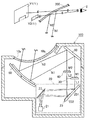
HUD装置100は、例えば自動車に搭載されるものであり、図1に示すように、筐体10と、投影装置20と、第一スクリーン(第一結像部)30と、第二スクリーン(第二結像部)40と、平面鏡(リレー光学系)50と、凹面鏡(リレー光学系)60と、制御基板(図示しない)と、を備える。HUD装置100は、投影装置20が第一スクリーン30に投影した第一表示画像M1と、同じく投影装置20が第二スクリーン40に投影した第二表示画像M2とを、平面鏡50と凹面鏡60とで車両のフロントガラス200に向けて反射することで、ユーザEに対して第一表示画像M1の第一虚像V1と、第二表示画像M2の第二虚像V2とを表示する。
The
筐体10は、例えば黒色の遮光性合成樹脂から形成され、投影装置20、第一スクリーン30、第二スクリーン40、平面鏡50、凹面鏡60を内部に収納し、外部に制御基板(図示しない)が取り付けられる。
筐体10は、後述する表示光Nをフロントガラス200に通過させる開口部10aを有し、この開口部10aは、透光性カバー10bに覆われている。
The housing 10 is made of, for example, black light-shielding synthetic resin, and houses the
The housing 10 has an opening 10a that allows display light N to be described later to pass through the
投影装置20は、後述する第一表示画像M1を示す第一投影光L1と、第二表示画像M2を示す第二投影光L2とを、後述する第一スクリーン30と第二スクリーン40とに向けて出射し、第一スクリーン30及び第二スクリーン40上に第一表示画像M1,第二表示画像M2を結像するものである。投影装置20の詳細な構成については、後に詳述する。
The
第一スクリーン(第一結像部)30は、投影装置20から出射された第一投影光L1を背面で受光し、表面側に第一表示画像M1を表示する透過スクリーンであり、例えば、ホログラフィックディフューザ、マイクロレンズアレイ、拡散板等によって構成される。第一スクリーン30が第一表示画像M1を表示すると、この第一表示画像M1を示す第一表示光N1は、後述の平面鏡50、凹面鏡60によりフロントガラス200に投射され、フロントガラス200によりユーザEの方向(アイボックス)に反射される。これにより、ユーザEは、フロントガラス200の向こう側に第一虚像V1を視認することができる。なお、本実施形態において第一スクリーン30は、図2に示すように略矩形状の外縁部分の一部を矩形状に切り抜いた切り欠き部30aを設けた凹状の表示エリアを有する。従って、第一虚像V1も凹状の表示エリアを有する。なお、後述する第二投影光L2は、図2に示すように第一スクリーン30の切り欠き部30aを通って後述する第二スクリーン40に到達する。
The first screen (first imaging unit) 30 is a transmissive screen that receives the first projection light L1 emitted from the
第二スクリーン(第二結像部)40は、第一スクリーン30の切り欠き部30aの略相似形状である矩形状に形成され、投影装置20から出射された第二投影光L2を背面で受光し、表面側に第二表示画像M2を表示する透過スクリーンであり、第一スクリーン30と同様、例えば、ホログラフィックディフューザ、マイクロレンズアレイ、拡散板等によって構成される。第二スクリーン40が第二表示画像M2を表示すると、この第二表示画像M2を示す第二表示光N2は、後述の平面鏡50、凹面鏡60によりフロントガラス200に投射され、ユーザEから見たフロントガラス200の向こう側に第二虚像V2を表示する。
The second screen (second imaging unit) 40 is formed in a rectangular shape that is substantially similar to the
図1に示すように、第一スクリーン30は、第二スクリーン40よりも投影装置20の近くに配置される。すなわち、第一スクリーン30からユーザEに向けて進行する第一表示光N1の光路長は、第二スクリーン40からユーザEに向けて進行する第二表示光N2の光路長よりも長くなる。それゆえ、ユーザEから第一虚像V1が表示される位置までの距離(表示距離)は、ユーザEから第二虚像V2が表示される位置までの距離(表示距離)よりも長くなるので、本実施形態におけるHUD装置100は、第一虚像V1が第二虚像V2よりも遠くの位置にあるように表示することができる。なお、本実施形態においては、第一虚像V1の表示距離は5mであり、第二虚像V2の表示距離は2mである。
As shown in FIG. 1, the
また、第一スクリーン30は、第一スクリーン30からユーザEに向かう第一表示光N1の光軸に対して所定の角度(0度も含む)を有するように配置され、そして、第二スクリーン40も同様に、第二スクリーン40からユーザEに向かう第二表示光N2の光軸に対して所定の角度(0度も含む)を有するように配置されている。なお、第一スクリーン30(第二スクリーン40)が第一表示光N1の光軸に対して所定の角度を持つ場合においても後述する凹面鏡60の自由曲面により、ユーザEの前方視線に対して第一虚像V1及び第二虚像V2が概ね垂直に向かい合うように結像される。ユーザEが第一虚像V1(第二虚像V2)を視認した際、第一虚像V1(第二虚像V2)内のどの領域でも表示距離が一定となり、ユーザEが焦点移動をしなくても第一虚像V1(第二虚像V2)全体を視認しやすくすることができる。
In addition, the
平面鏡(リレー光学系)50は、例えば合成樹脂やガラス材料からなる基材の表面に、蒸着等の手段により反射膜を形成したものであり、第一スクリーン30,第二スクリーン40から出射した第一表示光N1,第二表示光N2を、凹面鏡60に向けて反射する。
The plane mirror (relay optical system) 50 is formed by forming a reflective film on the surface of a base material made of, for example, a synthetic resin or a glass material by means of vapor deposition or the like, and is emitted from the
凹面鏡(リレー光学系)60は、例えば合成樹脂材料からなる基材の表面に、蒸着等の手段により反射膜を形成したものであり、平面鏡30で反射した第一表示光N1,第二表示光N2をさらに反射させ、フロントガラス200に向けて出射する凹状の自由曲面を有するミラーである。凹面鏡60で反射した第一表示光N1,第二表示光N2は、筐体10の開口部10aに設けられた透光性カバー10bを透過して、フロントガラス200に到達する。フロントガラス200で反射された第一表示光N1,第二表示光N2は、フロントガラス200の前方位置に第一虚像V1及び第二虚像V2を形成する。これにより、HUD装置100は、虚像V(第一虚像V1及び第二虚像V2)とフロントガラス200の前方に実際に存在する外景等の双方を、ユーザEに視認させることができる。なお、凹面鏡60は拡大鏡としての機能を有し、投影装置20に表示された表示画像Mを拡大してフロントガラス200側へ反射する。すなわち、ユーザEに視認される第一虚像V1,第二虚像V2は投影装置20が表示する第一表示画像M1,第二表示画像M2が拡大した像である。また、凹面鏡60は、フロントガラス200が曲面であることに起因する第一虚像V1及び第二虚像V2の歪みを軽減する機能も有する。以下に、投影装置20の具体的な構成を説明する。
The concave mirror (relay optical system) 60 is obtained by forming a reflective film on the surface of a base material made of, for example, a synthetic resin material by means such as vapor deposition, and the first display light N1 reflected by the
投影装置20は、図1に示すように、第一投影光L1,第二投影光L2を生成して出射する表示器21と、この表示器21から入射した第一投影光L1,第二投影光L2を反射して折り返すフォールドミラー22と、フォールドミラー22から入射した光の結像距離を調整する結像位置調整ミラー23と、を備え、投影装置20から異なる距離だけ離れた第一スクリーン30及び第二スクリーン40のそれぞれに第一投影光L1及び第二投影光L2を結像させる。
As shown in FIG. 1, the
表示器21は、DMD(Digital MicroMirror Device)やLCOS(登録商標:Liquid Crystal On Silicon)などの反射型表示素子やTFT(Thin Film transistor)液晶パネルなどの透過型表示素子を有し、図示しない制御基板からの制御信号に基づき、第一表示画像M1及び第二表示画像M2を表示させるための第一投影光L1及び第二投影光L2をフォールドミラー22に向けて出射する。なお、表示器21は、第一スクリーン30,第二スクリーン40,平面鏡50,凹面鏡60,フロントガラス200などを介してユーザEに視認される際に、歪んだ虚像V(第一虚像V1,第二虚像V2)にならないように、それぞれの光学部材の光学特性及び配置などを考慮して予め歪ませた表示画像M(第一表示画像M1,第二表示画像M2)を表示するように制御される。
The
フォールドミラー22は、例えば合成樹脂やガラス材料からなる基材の表面に、蒸着等の手段により反射膜を形成したものであり、表示器21から出射された第一投影光L1及び第二投影光L2を後述する結像位置調整ミラー23に反射する平面鏡である。フォールドミラー22を設けることで、投影装置20のパッケージをよりコンパクトにすることができる。なお、表示器21から結像位置調整ミラー23までの間にフォールドミラー22を複数設けてもよく、またフォールドミラー22を省略してもよい。
The
結像位置調整ミラー23は、例えば合成樹脂材料やガラス材料などからなる基材の表面に蒸着等の手段により反射膜を形成したものであり、同一基材上に、第一投影光L1を受光する第一反射面231と、第二投影光L2を受光する第二反射面232とを有する。本実施形態において、第一反射面231は、反射面が平面で形成され、受光した第一投影光L1を、結像距離を変化させずに第一スクリーン30に反射することで第一スクリーン30の表面側に第一表示画像M1を結像する。また、第二反射面232は、反射面が凸の自由曲面で形成され、受光した第二投影光L2を、結像距離を長く変化させて第二スクリーン40に反射することで第二スクリーン40の表面側に第二表示画像M2を結像する。
The imaging
すなわち、本実施形態における結像位置調整ミラー23は、第一投影光L1を反射する第一反射面231と、第二投影光L2を反射する第二反射面232との曲面形状が異なるので、1つの表示器21からの投影光Lを受光するだけで第一投影光L1と第二投影光L2とで結像距離を異ならせることができる。従って、ユーザEが視認する第一虚像V1と第二虚像V2とを異なる表示距離で表示することができ、第一虚像V1として表示される情報と、第二虚像V2として表示される情報とで差別化することができ、情報の識別性を高めることができる。また、同一の表示器21から出射される少なくとも第一投影光L1と第二投影光L2との結像距離を異ならせることができるため、表示器を複数設ける場合と比較してコストを抑えることができる。
That is, the imaging
また、結像位置調整ミラー23における第一反射面231と第二反射面232とは、同一基材上に形成されているため、表示器21からの投影光Lを結像位置調整ミラー23に照射するだけで少なくとも第一投影光L1と第二投影光L2との結像距離を異ならせることができるため、投影光Lの光路を複雑化することなく省スペースを実現することができる。
Further, since the first reflecting
また、本実施形態における結像位置調整ミラー23は、同一基材上に第一投影光L1と第二投影光L2との結像距離を異ならせる第一反射面231と第二反射面232とを形成しているため、第一反射面231と第二反射面232との相対的な位置が組み立て誤差などでずれにくく、精度よく第一投影光L1と第二投影光L2とを第一スクリーン30及び第二スクリーン40に結像させることができる。
In addition, the imaging
また、本実施形態における表示器21は、結像位置調整ミラー23の第一反射面231と第二反射面232との境界付近には画像を生成するための投影光Lを投射しない。斯かる構成により、投影光Lの結像位置調整ミラー23に対する投影位置がHUD装置100の組み付け誤差や振動などによってずれてしまった場合でも、第一スクリーン30に映したい第一表示画像M1が第二スクリーン40に映されてしまうことを防止することができる。
Further, the
また、本実施形態における結像位置調整ミラー23の一部(第一反射面231)は平面で形成されるため、表示器21から投射される投射光Lを歪ませることなく反射させることができる。また、結像位置調整ミラー23の設計や製造が容易になり設計製造コストを削減することができる。
In addition, since a part of the imaging position adjustment mirror 23 (first reflection surface 231) in the present embodiment is formed as a flat surface, the projection light L projected from the
以上が、本実施形態におけるHUD装置100の説明であるが、本発明は上記実施形態及び図面によって限定されるものではない。これらに変更(構成要素の削除も含む)を加えることができるのはもちろんである。以下に変形例の一例を示す。
The above is the description of the
上記実施形態において、第一反射面231が平面であり、第二反射面232が凸の自由曲面であるものを説明したが、第一反射面231及び第二反射面232の反射面の形状は、第一投影光L1と第二投影光L2の結像距離を異ならせることができればよいので、これに限定されない。反射面を凸状にすることで結像距離を長くすることができ、一方、凹状にすることで結像距離を短くすることができる。なお、第一反射面231及び第二反射面232は、反射領域全体で同じ曲面形状を有する必要はなく、反射領域によって異なっていてもよい。
In the said embodiment, although the 1st
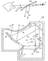
上記実施形態において、第一スクリーン30は、第一スクリーン30からユーザEに向かう第一表示光N1の光軸に対して所定の角度を有するように配置され、そして、第二スクリーン40も同様に、第二スクリーン40からユーザEに向かう第二表示光N2の光軸に対して所定の角度を有するように配置されていたが、これに限定されない。第一スクリーン30または/および第二スクリーン40を、ユーザEに向かう第一表示光N1(第二表示光N2)の光軸に対して所定の角度以上傾けて配置してもよい。具体的には、図3に示すように、第一スクリーン30を第一表示光N1の光軸に対して所定の角度以上傾けて配置し、傾けて配置した第一スクリーン30と表示器21との間の第一投影光L1の光路長を考慮して、第一反射面231の曲面形状を徐変することで第一投影光L1の結像距離を徐変することができる。従って、第一スクリーン30を光軸に対して所定の角度以上傾けた場合でも第一スクリーン30の広い範囲(全領域も含む)で第一表示画像M1を結像させることができ、ユーザEから奥行き感があり、ぼやけていない第一虚像V1を視認させることができる。
In the said embodiment, the
また、第一スクリーン30の第一投影光L1の光軸に対する傾きは、第二スクリーン40の第二投影光L2の光軸に対する傾きと異ならせてもよい。斯かる構成により、2つの虚像間(第一虚像V1と第二虚像V2)とを立体的に差別化することができ、それぞれの情報を区別してユーザEに認識させやすくすることができる。
Further, the inclination of the
また、上記実施形態では、表示器21が出射する第一投影光L1または/および第二投影光L2の結像距離を調整する結像位置調整ミラー23を、図4に示すように複数の結像位置調整ミラー23aと結像位置調整ミラー23bとによって構成してもよい。
In the above embodiment, the image forming
また、上記実施形態では、第一反射面231と第二反射面232を同じ基材上に配置したが、別々の基材上にそれぞれ配置されるものであってもよい。
Moreover, in the said embodiment, although the 1st
また、第一反射面231と第二反射面232とは、連続した反射膜で形成されてもよく、第一反射面231と第二反射面232との境界付近で反射膜を形成しなくてもよい。
Further, the first reflecting
また、上記実施形態において、第一スクリーン30及び第二スクリーン40は概ね矩形状としたが、第一スクリーン30及び第二スクリーン40の形状は、六角形や八角形などの多角形状であってもよい。
Moreover, in the said embodiment, although the
また、以上の説明では、本発明の理解を容易にするために、重要でない公知の技術的事項の説明を適宜省略した。 Moreover, in the above description, in order to make an understanding of this invention easy, description of the unimportant known technical matter was abbreviate | omitted suitably.
100 HUD装置(ヘッドアップディスプレイ装置)、10 筐体、20 投影装置、21 表示器、22 フォールドミラー、23 結像位置調整ミラー、30 第一スクリーン、40 第二スクリーン、50 平面鏡、60 凹面鏡、L 投影光、L1 第一投影光、L2 第二投影光、M1 第一表示画像、M2 第二表示画像、N1 第一表示光、N2 第二表示光、V 虚像V1 第一虚像V2 第二虚像 100 HUD device (head up display device), 10 housing, 20 projection device, 21 display, 22 fold mirror, 23 imaging position adjustment mirror, 30 first screen, 40 second screen, 50 plane mirror, 60 concave mirror, L Projection light, L1 first projection light, L2 second projection light, M1 first display image, M2 second display image, N1 first display light, N2 second display light, V virtual image V1 first virtual image V2 second virtual image
Claims (16)
前記表示器から出射される前記投影光を受光し、入射した前記投影光のうち少なくとも一部の前記投影光の結像距離を変えて結像距離の異なる複数の投影光に変換して反射する結像位置調整ミラーと、を備える投影装置において、
第二スクリーンに前記投影光のうち結像距離が長い投影光を結像させ、
前記第二スクリーンよりも前記投影装置に近い位置に配置される第一スクリーンに前記投影光のうち結像距離が短い投影光を結像させる、
ことを特徴とする投影装置。 A display that emits projection light for displaying a display image at a predetermined position;
The projection light emitted from the display is received, converted into a plurality of projection lights having different imaging distances by changing the imaging distance of at least some of the incident projection light, and reflected. An image forming position adjusting mirror ;
Let the second screen form a projection light having a long imaging distance among the projection light,
Imaging a projection light having a short imaging distance among the projection light on a first screen arranged at a position closer to the projection device than the second screen;
A projection apparatus characterized by that.
ことを特徴とする請求項1に記載の投影装置。 The imaging position adjusting mirror has a curved surface that changes an imaging distance in a predetermined region.
The projection apparatus according to claim 1.
ことを特徴とする請求項1に記載の投影装置。 The imaging position adjusting mirror is configured to reflect a part of the projection light as a first projection light having a first imaging distance toward a predetermined region, and a part of the projection light. A second reflecting surface that reflects toward a region different from the first projection light as a second projection light having a second imaging distance shorter than the first imaging distance,
The projection apparatus according to claim 1.
ことを特徴とする請求項3に記載の投影装置。 The first reflecting surface and the second reflecting surface are formed on the same substrate.
The projection apparatus according to claim 3.
ことを特徴とする請求項3に記載の投影装置。 The indicator does not project the projection light near a boundary between the first reflecting surface and the second reflecting surface;
The projection apparatus according to claim 3.
ことを特徴とする請求項3に記載の投影装置。 Either the first reflecting surface or the second reflecting surface is a plane,
The projection apparatus according to claim 3.
ことを特徴とする請求項3に記載の投影装置。 The first reflective surface or / and the second reflective surface have a curved surface that gradually changes the imaging distance of the projection light according to the angle of view of the display image.
The projection apparatus according to claim 3.
投影光を出射する投影部と、
前記投影部から出射される前記投影光を受光し、入射した前記投影光のうち少なくとも一部の前記投影光の結像距離を変えて結像距離の異なる複数の投影光に変換して反射する結像位置調整ミラーと、
前記投影光のうち結像距離が長い投影光を結像する第二スクリーンと、
前記第二スクリーンより前記投影面より離れた位置に配置され、前記投影光のうち結像距離が短い投影光を結像する第一スクリーンと、を備える、
ことを特徴とするヘッドアップディスプレイ装置。 In a head-up display device that projects a display image on a projection surface and visually recognizes the display image as a virtual image,
A projection unit for emitting projection light;
The projection light emitted from the projection unit is received, converted into a plurality of projection lights having different imaging distances by changing the imaging distance of at least some of the incident projection light, and reflected. An imaging position adjustment mirror;
A second screen for imaging projection light having a long imaging distance among the projection light;
Wherein arranged in the second screen than away from the projection plane position, and a first screen for forming an image formation distance is short projection light of the projection light,
A head-up display device.
ことを特徴とする請求項8に記載のヘッドアップディスプレイ装置。 The imaging position adjusting mirror has a curved surface that changes an imaging distance in a predetermined region.
The head-up display device according to claim 8.
ことを特徴とする請求項8に記載のヘッドアップディスプレイ装置。 The imaging position adjusting mirror includes a first reflecting surface that reflects a part of the projection light as a first projection light having a first imaging distance toward the first screen, and a part of the projection light. A second reflecting surface that reflects toward the second screen as a second projection light having a second imaging distance shorter than the first imaging distance,
The head-up display device according to claim 8.
ことを特徴とする請求項10に記載のヘッドアップディスプレイ装置。 The first reflecting surface and the second reflecting surface are formed on the same substrate.
The head-up display device according to claim 10.
ことを特徴とする請求項10に記載のヘッドアップディスプレイ装置。 The projection unit does not project the projection light near a boundary between the first reflection surface and the second reflection surface;
The head-up display device according to claim 10.
ことを特徴とする請求項10に記載のヘッドアップディスプレイ装置。 Either the first reflecting surface or the second reflecting surface is a plane,
The head-up display device according to claim 10.
ことを特徴とする請求項10に記載のヘッドアップディスプレイ装置。 The first screen or / and the second screen are arranged to be inclined with respect to the optical axis of the projection light.
The head-up display device according to claim 10.
ことを特徴とする請求項14に記載のヘッドアップディスプレイ装置。 The inclination of the first screen with respect to the optical axis of the projection light is different from the inclination of the second screen with respect to the optical axis of the projection light.
The head-up display device according to claim 14.
ことを特徴とする請求項14に記載のヘッドアップディスプレイ装置。
The first reflective surface or / and the second reflective surface have a curved surface that gradually changes the imaging distance of the projection light according to the angle of view of the display image.
The head-up display device according to claim 14.
Priority Applications (5)
| Application Number | Priority Date | Filing Date | Title |
|---|---|---|---|
| JP2014167780A JP5930231B2 (en) | 2014-08-20 | 2014-08-20 | Projection device and head-up display device |
| US15/504,591 US10302939B2 (en) | 2014-08-20 | 2015-08-07 | Projection device and head-up display device |
| CN201580043976.XA CN106605166B (en) | 2014-08-20 | 2015-08-07 | Projection apparatus and head-up display apparatus |
| EP15834597.5A EP3185061B1 (en) | 2014-08-20 | 2015-08-07 | Projection device and head-up display device |
| PCT/JP2015/072526 WO2016027706A1 (en) | 2014-08-20 | 2015-08-07 | Projection device and head-up display device |
Applications Claiming Priority (1)
| Application Number | Priority Date | Filing Date | Title |
|---|---|---|---|
| JP2014167780A JP5930231B2 (en) | 2014-08-20 | 2014-08-20 | Projection device and head-up display device |
Related Child Applications (1)
| Application Number | Title | Priority Date | Filing Date |
|---|---|---|---|
| JP2016090496A Division JP6414131B2 (en) | 2016-04-28 | 2016-04-28 | Projection device and head-up display device |
Publications (2)
| Publication Number | Publication Date |
|---|---|
| JP2016045252A JP2016045252A (en) | 2016-04-04 |
| JP5930231B2 true JP5930231B2 (en) | 2016-06-08 |
Family
ID=55350651
Family Applications (1)
| Application Number | Title | Priority Date | Filing Date |
|---|---|---|---|
| JP2014167780A Active JP5930231B2 (en) | 2014-08-20 | 2014-08-20 | Projection device and head-up display device |
Country Status (5)
| Country | Link |
|---|---|
| US (1) | US10302939B2 (en) |
| EP (1) | EP3185061B1 (en) |
| JP (1) | JP5930231B2 (en) |
| CN (1) | CN106605166B (en) |
| WO (1) | WO2016027706A1 (en) |
Cited By (1)
| Publication number | Priority date | Publication date | Assignee | Title |
|---|---|---|---|---|
| US11036045B2 (en) | 2017-03-14 | 2021-06-15 | Pioneer Corporation | Display device |
Families Citing this family (60)
| Publication number | Priority date | Publication date | Assignee | Title |
|---|---|---|---|---|
| FR3029647B1 (en) * | 2014-12-05 | 2018-02-02 | Valeo Comfort And Driving Assistance | HIGH HEAD DISPLAY WITH SIDE IMAGE GENERATOR |
| JP6580328B2 (en) * | 2015-01-20 | 2019-09-25 | クラリオン株式会社 | Head-up display device for vehicle |
| JP6558017B2 (en) * | 2015-03-27 | 2019-08-14 | 日本精機株式会社 | Head-up display |
| JP6597022B2 (en) * | 2015-07-28 | 2019-10-30 | 日本精機株式会社 | Head-up display device |
| JP2017097268A (en) * | 2015-11-27 | 2017-06-01 | 株式会社リコー | Image display unit and vehicle |
| EP3415974B1 (en) * | 2016-02-08 | 2021-03-24 | Nippon Seiki Co., Ltd. | Display device and head-up display |
| EP3415973B1 (en) * | 2016-02-08 | 2020-11-25 | Nippon Seiki Co., Ltd. | Display device and head-up display |
| JP6598701B2 (en) * | 2016-02-15 | 2019-10-30 | アルパイン株式会社 | In-vehicle display device |
| WO2017169610A1 (en) * | 2016-03-30 | 2017-10-05 | 日本精機株式会社 | Head-up display device |
| WO2017188008A1 (en) | 2016-04-26 | 2017-11-02 | 日本精機株式会社 | Display device |
| JP6819679B2 (en) * | 2016-05-09 | 2021-01-27 | 日本精機株式会社 | Head-up display device |
| JP6545128B2 (en) * | 2016-07-25 | 2019-07-17 | 富士フイルム株式会社 | Head-up display device |
| US11237390B2 (en) | 2016-09-21 | 2022-02-01 | Nec Corporation | Display system |
| US10814723B2 (en) * | 2016-10-04 | 2020-10-27 | Maxell, Ltd. | Projection optical system, and head-up display device |
| JP6900165B2 (en) * | 2016-10-04 | 2021-07-07 | 矢崎総業株式会社 | Vehicle display device |
| JP2018086915A (en) * | 2016-11-29 | 2018-06-07 | コニカミノルタ株式会社 | Head-up display device |
| GB2557231B (en) | 2016-11-30 | 2020-10-07 | Jaguar Land Rover Ltd | Multi-depth display apparatus |
| GB2579117B (en) * | 2016-11-30 | 2021-05-26 | Jaguar Land Rover Ltd | Multi-depth augmented reality display |
| GB2557227A (en) | 2016-11-30 | 2018-06-20 | Jaguar Land Rover Ltd | Multi-depth display apparatus |
| GB2557229A (en) | 2016-11-30 | 2018-06-20 | Cambridge Entpr Ltd | Multi-depth augmented reality display |
| GB2557230B (en) * | 2016-11-30 | 2019-09-25 | Jaguar Land Rover Ltd | Multi-depth augmented reality display |
| KR101899981B1 (en) * | 2016-12-02 | 2018-09-19 | 엘지전자 주식회사 | Head Up Display for Vehicle |
| CN110073271A (en) | 2016-12-15 | 2019-07-30 | 阿尔卑斯阿尔派株式会社 | Image display device |
| JP2018095157A (en) * | 2016-12-15 | 2018-06-21 | アルプス電気株式会社 | On-vehicle display device |
| CN108241209A (en) * | 2016-12-23 | 2018-07-03 | 怡利电子工业股份有限公司 | Multiple display, which comes back, shows equipment |
| JP6601431B2 (en) | 2017-02-03 | 2019-11-06 | 株式会社デンソー | Head-up display device |
| JP6601438B2 (en) * | 2017-02-21 | 2019-11-06 | 株式会社デンソー | Head-up display device |
| DE112018001048B4 (en) | 2017-02-28 | 2024-04-11 | Panasonic Intellectual Property Management Co., Ltd. | Display device, method for controlling the display device, program, recording medium and moving body equipped with the display device |
| US11508257B2 (en) * | 2017-03-07 | 2022-11-22 | 8259402 Canada Inc. | Method to control a virtual image in a display |
| JP6854448B2 (en) * | 2017-03-31 | 2021-04-07 | パナソニックIpマネジメント株式会社 | Display device and mobile body equipped with it |
| JP6709960B2 (en) * | 2017-03-31 | 2020-06-17 | パナソニックIpマネジメント株式会社 | Display device and moving body including the same |
| CN106896506B (en) | 2017-04-28 | 2019-07-26 | 京东方科技集团股份有限公司 | A kind of head-up display, head-up display method and vehicle |
| JP6717264B2 (en) * | 2017-06-08 | 2020-07-01 | 株式会社Jvcケンウッド | Virtual image display device, intermediate image forming unit, and image display light generation unit |
| CN109143576B (en) * | 2017-06-27 | 2021-01-22 | 京东方科技集团股份有限公司 | Display system, display method thereof and vehicle |
| CN107238936A (en) * | 2017-07-11 | 2017-10-10 | 京东方科技集团股份有限公司 | 3 d display device, system and stereo display method |
| KR20190011944A (en) * | 2017-07-26 | 2019-02-08 | 주식회사 크레모텍 | 3d head-up display apparatus for vehicle and display method using the same |
| EP3677947A4 (en) | 2017-08-29 | 2021-05-26 | Nippon Seiki Co., Ltd. | Headup display device |
| CN108152957A (en) * | 2017-12-25 | 2018-06-12 | 宁波均胜科技有限公司 | A kind of vehicle-mounted head-up-display system and the error calibrating method based on the system |
| CN107991777A (en) * | 2017-12-25 | 2018-05-04 | 宁波均胜科技有限公司 | A kind of vehicle-mounted head-up-display system with error correction function |
| JP7140504B2 (en) * | 2018-02-14 | 2022-09-21 | 矢崎総業株式会社 | projection display |
| CN110554497A (en) * | 2018-05-31 | 2019-12-10 | 东莞创奕电子科技有限公司 | Display device and vehicle head-up display system thereof |
| US20200018977A1 (en) * | 2018-07-13 | 2020-01-16 | Conserve & Associates , Inc. | Display device and automobile head-up display system using the same |
| EP3599495A1 (en) * | 2018-07-24 | 2020-01-29 | ScioTeq BVBA | Collimated visual display system |
| US20200033613A1 (en) * | 2018-07-26 | 2020-01-30 | Varjo Technologies Oy | Display apparatus and method of displaying using curved optical combiner |
| CN108957755B (en) * | 2018-07-27 | 2021-04-30 | 京东方科技集团股份有限公司 | Display assembly, control method thereof, head-up display and automobile |
| US11122243B2 (en) | 2018-11-19 | 2021-09-14 | Flightsafety International Inc. | Method and apparatus for remapping pixel locations |
| CA3120646A1 (en) * | 2018-11-20 | 2020-05-28 | FlightSafety International | Rear projection simulator with freeform fold mirror |
| TWI676823B (en) * | 2018-12-26 | 2019-11-11 | 中強光電股份有限公司 | Head-up display apparatus |
| JP7451083B2 (en) * | 2019-01-31 | 2024-03-18 | 株式会社Jvcケンウッド | heads up display device |
| CN109597208A (en) * | 2019-01-31 | 2019-04-09 | 延锋伟世通电子科技(上海)有限公司 | A kind of spuious photo structure of vehicle-mounted head-up display elimination |
| JP2020008869A (en) * | 2019-09-05 | 2020-01-16 | アルパイン株式会社 | On-vehicle display device |
| US20220365345A1 (en) * | 2019-09-19 | 2022-11-17 | Koito Manufacturing Co., Ltd. | Head-up display and picture display system |
| CN114397755A (en) * | 2020-05-15 | 2022-04-26 | 华为技术有限公司 | Display device, method and vehicle |
| EP4163156A4 (en) * | 2020-06-08 | 2023-12-06 | Panasonic Intellectual Property Management Co., Ltd. | Display system |
| US11169377B1 (en) * | 2020-09-16 | 2021-11-09 | E-Lead Electronic Co., Ltd. | Multi-focal plane head-up display |
| CN115248503A (en) * | 2021-04-27 | 2022-10-28 | 矽创电子股份有限公司 | Optical imaging device with double display |
| CN115857165A (en) * | 2021-06-30 | 2023-03-28 | 上海天马微电子有限公司 | Head-up display |
| CN115032798A (en) * | 2022-07-06 | 2022-09-09 | 泽景(西安)汽车电子有限责任公司 | AR-HUD and its long and short sight double optical path system |
| CN115128812B (en) * | 2022-07-06 | 2024-08-27 | 泽景(西安)汽车电子有限责任公司 | Remote-near view dual-light path system of AR-HUD and AR-HUD |
| DE102023105900B3 (en) | 2023-03-09 | 2024-05-29 | Bayerische Motoren Werke Aktiengesellschaft | Mirror replacement HUD with a stepped display arrangement for a vehicle |
Family Cites Families (13)
| Publication number | Priority date | Publication date | Assignee | Title |
|---|---|---|---|---|
| US4812028A (en) * | 1984-07-23 | 1989-03-14 | Nikon Corporation | Reflection type reduction projection optical system |
| JPH075886U (en) * | 1993-06-25 | 1995-01-27 | 日本精機株式会社 | Vehicle display |
| JPH07257228A (en) * | 1994-03-18 | 1995-10-09 | Nissan Motor Co Ltd | Display device for vehicle |
| JP2003237412A (en) | 2002-02-14 | 2003-08-27 | Denso Corp | Vehicular head-up display device |
| JP3917498B2 (en) * | 2002-10-10 | 2007-05-23 | 株式会社日本自動車部品総合研究所 | Split display device for vehicle |
| JP2006106254A (en) * | 2004-10-04 | 2006-04-20 | Denso Corp | Head-up display for vehicle |
| JP2010164941A (en) * | 2008-10-30 | 2010-07-29 | Honda Motor Co Ltd | Display device for vehicle |
| JP2011064902A (en) * | 2009-09-16 | 2011-03-31 | Toshiba Corp | Display device and display method |
| US8277055B2 (en) * | 2010-07-21 | 2012-10-02 | Delphi Technologies, Inc. | Multiple view display system using a single projector and method of operating the same |
| JP5392276B2 (en) * | 2011-02-03 | 2014-01-22 | 株式会社デンソー | Virtual image display device |
| JP2013111999A (en) * | 2011-11-25 | 2013-06-10 | Nippon Seiki Co Ltd | Vehicle display device |
| JP2015034919A (en) * | 2013-08-09 | 2015-02-19 | 株式会社デンソー | Information display device |
| JP6597022B2 (en) * | 2015-07-28 | 2019-10-30 | 日本精機株式会社 | Head-up display device |
-
2014
- 2014-08-20 JP JP2014167780A patent/JP5930231B2/en active Active
-
2015
- 2015-08-07 CN CN201580043976.XA patent/CN106605166B/en active Active
- 2015-08-07 US US15/504,591 patent/US10302939B2/en active Active
- 2015-08-07 EP EP15834597.5A patent/EP3185061B1/en active Active
- 2015-08-07 WO PCT/JP2015/072526 patent/WO2016027706A1/en active Application Filing
Cited By (1)
| Publication number | Priority date | Publication date | Assignee | Title |
|---|---|---|---|---|
| US11036045B2 (en) | 2017-03-14 | 2021-06-15 | Pioneer Corporation | Display device |
Also Published As
| Publication number | Publication date |
|---|---|
| WO2016027706A1 (en) | 2016-02-25 |
| CN106605166B (en) | 2020-01-03 |
| CN106605166A (en) | 2017-04-26 |
| EP3185061A4 (en) | 2018-01-10 |
| US20170235138A1 (en) | 2017-08-17 |
| EP3185061B1 (en) | 2019-02-27 |
| US10302939B2 (en) | 2019-05-28 |
| EP3185061A1 (en) | 2017-06-28 |
| JP2016045252A (en) | 2016-04-04 |
Similar Documents
| Publication | Publication Date | Title |
|---|---|---|
| JP5930231B2 (en) | Projection device and head-up display device | |
| KR101408523B1 (en) | Head-up display apparatus | |
| JP6414131B2 (en) | Projection device and head-up display device | |
| JP6738543B2 (en) | Display device and head-up display | |
| JP6737291B2 (en) | Display device and head-up display | |
| WO2016208379A1 (en) | Screen device and head-up display device | |
| KR102192933B1 (en) | Virtual image display device, intermediate image forming unit, and image display light generating unit | |
| US20210063736A1 (en) | Headup display device | |
| JP6593461B2 (en) | Virtual image display device | |
| JP6593462B2 (en) | Virtual image display device | |
| JP6579180B2 (en) | Virtual image display device | |
| WO2017141896A1 (en) | Head-up display device | |
| WO2015045937A1 (en) | Projection display device | |
| JPWO2017188008A1 (en) | Display device | |
| JP6766828B2 (en) | Head-up display device | |
| JP2017142284A (en) | Display device and head-up display | |
| JP6593464B2 (en) | Virtual image display device | |
| JP6593465B2 (en) | Virtual image display device | |
| JP7359152B2 (en) | heads up display device | |
| JP2018105939A (en) | Head-up display device | |
| JP6593463B2 (en) | Virtual image display device | |
| JP6593393B2 (en) | Virtual image display device |
Legal Events
| Date | Code | Title | Description |
|---|---|---|---|
| A621 | Written request for application examination |
Free format text: JAPANESE INTERMEDIATE CODE: A621 Effective date: 20160125 |
|
| A871 | Explanation of circumstances concerning accelerated examination |
Free format text: JAPANESE INTERMEDIATE CODE: A871 Effective date: 20160127 |
|
| A975 | Report on accelerated examination |
Free format text: JAPANESE INTERMEDIATE CODE: A971005 Effective date: 20160203 |
|
| A131 | Notification of reasons for refusal |
Free format text: JAPANESE INTERMEDIATE CODE: A131 Effective date: 20160209 |
|
| A521 | Request for written amendment filed |
Free format text: JAPANESE INTERMEDIATE CODE: A523 Effective date: 20160318 |
|
| TRDD | Decision of grant or rejection written | ||
| A01 | Written decision to grant a patent or to grant a registration (utility model) |
Free format text: JAPANESE INTERMEDIATE CODE: A01 Effective date: 20160406 |
|
| A61 | First payment of annual fees (during grant procedure) |
Free format text: JAPANESE INTERMEDIATE CODE: A61 Effective date: 20160419 |
|
| R150 | Certificate of patent or registration of utility model |
Ref document number: 5930231 Country of ref document: JP Free format text: JAPANESE INTERMEDIATE CODE: R150 |