WO2017183706A1 - マルチプレクサ、及び該マルチプレクサを備えた撮影装置 - Google Patents
マルチプレクサ、及び該マルチプレクサを備えた撮影装置 Download PDFInfo
- Publication number
- WO2017183706A1 WO2017183706A1 PCT/JP2017/015967 JP2017015967W WO2017183706A1 WO 2017183706 A1 WO2017183706 A1 WO 2017183706A1 JP 2017015967 W JP2017015967 W JP 2017015967W WO 2017183706 A1 WO2017183706 A1 WO 2017183706A1
- Authority
- WO
- WIPO (PCT)
- Prior art keywords
- packet data
- data
- camera
- previous
- transmitted
- Prior art date
- Legal status (The legal status is an assumption and is not a legal conclusion. Google has not performed a legal analysis and makes no representation as to the accuracy of the status listed.)
- Ceased
Links
Images



Classifications
-
- H—ELECTRICITY
- H04—ELECTRIC COMMUNICATION TECHNIQUE
- H04N—PICTORIAL COMMUNICATION, e.g. TELEVISION
- H04N7/00—Television systems
- H04N7/08—Systems for the simultaneous or sequential transmission of more than one television signal, e.g. additional information signals, the signals occupying wholly or partially the same frequency band, e.g. by time division
- H04N7/0806—Systems for the simultaneous or sequential transmission of more than one television signal, e.g. additional information signals, the signals occupying wholly or partially the same frequency band, e.g. by time division the signals being two or more video signals
-
- G—PHYSICS
- G06—COMPUTING OR CALCULATING; COUNTING
- G06F—ELECTRIC DIGITAL DATA PROCESSING
- G06F11/00—Error detection; Error correction; Monitoring
- G06F11/07—Responding to the occurrence of a fault, e.g. fault tolerance
- G06F11/08—Error detection or correction by redundancy in data representation, e.g. by using checking codes
-
- H—ELECTRICITY
- H04—ELECTRIC COMMUNICATION TECHNIQUE
- H04N—PICTORIAL COMMUNICATION, e.g. TELEVISION
- H04N17/00—Diagnosis, testing or measuring for television systems or their details
- H04N17/002—Diagnosis, testing or measuring for television systems or their details for television cameras
-
- H—ELECTRICITY
- H04—ELECTRIC COMMUNICATION TECHNIQUE
- H04N—PICTORIAL COMMUNICATION, e.g. TELEVISION
- H04N21/00—Selective content distribution, e.g. interactive television or video on demand [VOD]
- H04N21/20—Servers specifically adapted for the distribution of content, e.g. VOD servers; Operations thereof
- H04N21/23—Processing of content or additional data; Elementary server operations; Server middleware
- H04N21/236—Assembling of a multiplex stream, e.g. transport stream, by combining a video stream with other content or additional data, e.g. inserting a URL [Uniform Resource Locator] into a video stream, multiplexing software data into a video stream; Remultiplexing of multiplex streams; Insertion of stuffing bits into the multiplex stream, e.g. to obtain a constant bit-rate; Assembling of a packetised elementary stream
- H04N21/2365—Multiplexing of several video streams
-
- H—ELECTRICITY
- H04—ELECTRIC COMMUNICATION TECHNIQUE
- H04N—PICTORIAL COMMUNICATION, e.g. TELEVISION
- H04N23/00—Cameras or camera modules comprising electronic image sensors; Control thereof
- H04N23/60—Control of cameras or camera modules
- H04N23/66—Remote control of cameras or camera parts, e.g. by remote control devices
- H04N23/661—Transmitting camera control signals through networks, e.g. control via the Internet
-
- H—ELECTRICITY
- H04—ELECTRIC COMMUNICATION TECHNIQUE
- H04N—PICTORIAL COMMUNICATION, e.g. TELEVISION
- H04N23/00—Cameras or camera modules comprising electronic image sensors; Control thereof
- H04N23/90—Arrangement of cameras or camera modules, e.g. multiple cameras in TV studios or sports stadiums
-
- H—ELECTRICITY
- H04—ELECTRIC COMMUNICATION TECHNIQUE
- H04N—PICTORIAL COMMUNICATION, e.g. TELEVISION
- H04N7/00—Television systems
- H04N7/10—Adaptations for transmission by electrical cable
- H04N7/102—Circuits therefor, e.g. noise reducers, equalisers, amplifiers
-
- H—ELECTRICITY
- H04—ELECTRIC COMMUNICATION TECHNIQUE
- H04N—PICTORIAL COMMUNICATION, e.g. TELEVISION
- H04N7/00—Television systems
- H04N7/18—Closed-circuit television [CCTV] systems, i.e. systems in which the video signal is not broadcast
Definitions
- the present invention relates to a multiplexer that transmits packet data received from at least two cameras to an external device, and a photographing apparatus including the multiplexer.
- FIG. 5 is a block diagram showing an example of a conventional structure of a multiplexer.
- the multiplexer 201 includes a video camera line 202 to which a plurality of cameras C11, C12, C13, and C14 are connected, and the video camera line. 202 is connected to the video system controller 203, and the video signal from each camera C 11,... Is transmitted to the video recorder or the video display 204.
- the multiplexer 201 shown in FIG. 5 uses an analog signal, image signals obtained by simultaneously photographing with a plurality of cameras C11,... Are sent from the video system controller 203 to the video recorder or video recorder. They could not be sent to the display 204 at the same time.
- image signals obtained by simultaneously photographing with a plurality of cameras C11,... are sent from the video system controller 203 to the video recorder or video recorder. They could not be sent to the display 204 at the same time.
- the photographing with the cameras C11,... Is performed sequentially without being performed at the same time there is a problem that the exposure time is required, and the photographing cannot be performed during that time.
- a large-capacity buffer for storing images is required, which causes a problem that the apparatus itself becomes large and expensive.
- the first aspect of the present invention is illustrated in FIG. 1 and includes a first receiving unit (1) that sequentially receives first packet data (PD1) that is an image signal from the first camera (C1).
- a transmitting unit (12) connected to the data combining unit (11) and transmitting the combined data (PDs) to the external device (2);
- the first packet data (PD1) continuously arranged in the composite data (PDs) is data smaller than the data for one screen
- the second packet data (PD2) continuously arranged in the combined data (PDs) relates to the multiplexer (1), which is smaller than the data for one screen.
- the second packet data (PD2) is image data of one pixel, a plurality of pixels, one line, or a plurality of lines.
- the data synthesizing unit (11) receives the first packet data (PD1) received by the first receiving unit (101) and / or the second receiving unit ( 102) includes a data storage unit (110) that sequentially stores the received second packet data (PD2).
- the fourth aspect of the present invention is the first camera (C1) and the second camera (C2), The multiplexer (1); With As illustrated in FIG. 3A, the first packet data (PD1) transmitted from the first camera (C1) to the first receiver (101) Packet data (PD1A) and the same content as the first previous packet data (PD1A), and after the first previous packet data (PD1A) is transmitted, are transmitted after a predetermined idle time (I1). First post-packet data (PD1B) As illustrated in FIG.
- Second post-packet data (PD2B) is the time width of noise (refer to symbol N in FIGS. 3A and 3B, hereinafter referred to as “low frequency noise”) generated at intervals of 10 ⁇ sec or more, and one low frequency noise (N) is generated.
- the first camera (C1) stores the first previous packet data (PD1A) and the first subsequent packet data (PD1B) in a state where an error detection code is added.
- the second camera (C2) receives the second previous packet data (PD2A) and the second subsequent packet data (PD2B) with an error detection code added thereto in the second receiving unit (102).
- the first reception unit (101) checks the error detection code from the first camera (C1) to check the first previous packet data (PD1A) or the first subsequent packet data (PD1B). ) Is detected, and the first previous packet data (PD1A) or the first subsequent packet data (PD1B) of which data corruption has not been detected is transmitted to the data synthesis unit (11).
- the second receiving unit (102) checks the error detection code from the second camera (C2) to check the second previous packet data (PD2A) or the second subsequent packet data (PD2B). ) Is detected, and the second previous packet data (PD2A) or the second subsequent packet data (PD2B) in which data corruption has not been detected is transmitted to the data synthesis unit (11). It is characterized by that.
- one first packet data (that is, first packet data continuously arranged in the combined data) is data smaller than data for one screen. Since one second packet data (that is, the second packet data continuously arranged in the composite data) is smaller than the data for one screen, it is like a frame buffer. A large-capacity buffer is not required, and the size and cost of the apparatus can be reduced accordingly.
- the transmission cable can be used even in a thin transmission cable such as 3CFB in an environment where a lot of low-frequency noise due to a power source or the like is generated.
- Machine vision can be configured by attaching industrial digital cameras to various inspection devices.
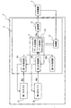
- FIG. 1 is a block diagram showing an example of the configuration of a multiplexer or the like according to the present invention.
- FIG. 2A is a data structure diagram for explaining the configuration of the first packet data
- FIG. 2B is a data structure diagram for explaining the configuration of the second packet data.
- FIG. 6C is a data structure diagram for explaining the composition of the composite data.
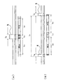
- FIG. 3A is a data structure diagram for explaining the first packet data and the like
- FIG. 3B is a data structure diagram for explaining the second packet data and the like.
- 4A and 4B are data structure diagrams for explaining the effects of the present invention.
- FIG. 5 is a block diagram showing an example of a conventional structure of a multiplexer.
- the multiplexer according to the present invention is illustrated by reference numeral 1 in FIG.
- a first reception unit 101 that sequentially receives image signals (hereinafter referred to as “first packet data”) PD1 from the first camera C1
- a second receiving unit 102 that sequentially receives image signals (hereinafter referred to as “second packet data”) PD2 from the second camera C2
- a data combining unit 11 connected to these receiving units 101 and 102 and combining packet data PD1 and PD2 from the receiving units 101 and 102 to create combined data PDs
- a transmitting unit 12 connected to the data combining unit 11 and transmitting the combined data PDs to the external device 2; It has.
- the synthesized data PDs created by the data synthesizing section 11 is obtained by alternately arranging the first packet data PD1 and the second packet data PD2 as illustrated in FIG. 2C.
- the one first packet data PD1 (that is, the first packet data PD1 continuously arranged in the combined data PDs) is data smaller than the data for one screen
- One second packet data PD2 (that is, second packet data PD2 continuously arranged in the composite data PDs) is set to be data smaller than data for one screen.
- the one first packet data PD1 and the one second packet data PD2 may be image data of one pixel. That is, as illustrated in FIG.
- image data (that is, image data for each pixel) sequentially transmitted from the first camera C1 to the first receiving unit 101 is PD11, PD12, and PD13.
- image data (that is, image data for each pixel) sequentially transmitted from the second camera C2 to the second receiving unit 102 is PD21 and PD22.
- the synthesized data PDs may be composed of PD11, PD21, PD12, PD22, PD13, PD23,...
- the one first packet data PD1 and the one second packet data PD2 may be image data of a plurality of pixels.
- the one first packet data PD1 and the one second packet data PD2 may be image data of one line.
- the one first packet data PD1 and the one second packet data PD2 may be image data of a plurality of lines.
- the number of the receiving units 101, 102,... May be two or more, and may be three as shown by reference numerals 101, 101, 103 in FIG.
- the number of receiving units is n (where n is an integer greater than or equal to 3), and each receiving unit is referred to as “first receiving unit”, “second receiving unit”,.
- the cameras connected to the respective receivers are referred to as “first cameras”, “second cameras”,..., “Nth cameras”, and
- first packet data”, “second packet data”,..., “Nth packet data” each receiving unit is connected to the data combining unit 11 and the combined data PDs are arranged in the order of the first packet data ⁇ the second packet data ⁇ ... ⁇ the nth packet data, and any of the packet data (that is, continuously arranged in the combined data, respectively).
- photographing by the cameras C1,... May be started by sending a trigger signal from the control unit 13.
- the data synthesizing unit 11 The first packet data PD1 received by the first receiving unit 101
- a data storage unit 110 that sequentially stores either one or both of them may be provided.
- the data for one screen of one camera for example, the first camera C1
- the data for one screen of another camera for example, the second camera C2
- To the external device 2 requires a large-capacity buffer such as a frame buffer, and the apparatus becomes large and expensive accordingly.
- one piece of the first packet data PD1 (that is, the first packet data PD1 continuously arranged in the composite data PDs) is smaller than the data for one screen.
- one second packet data PD2 (that is, second packet data PD2 continuously arranged in the composite data PDs) is data smaller than the data for one screen, A large-capacity buffer such as a buffer is not required, and the apparatus can be reduced in size and cost accordingly.
- FIG. 3A illustrates the first packet data PD1 described above (that is, the first packet data PD1 transmitted from the first camera C1 to the first receiving unit 101). As shown in the figure, it is composed of two packet data PD1A and PD1B having the same contents, and after a packet data (hereinafter referred to as "first previous packet data") PD1A is transmitted, a predetermined idle time I1 is left. The other packet data (hereinafter referred to as “first post-packet data”) PD1B may be transmitted.
- the second packet data PD2 described above (that is, the second packet data PD2 transmitted from the second camera C2 to the second receiving unit 102) is illustrated in FIG. 3B.
- the packet data is composed of two pieces of packet data PD2A and PD2B having the same contents, and after one packet data (hereinafter referred to as “second previous packet data”) PD2A is transmitted, a predetermined idle time I2 is left.
- the other packet data hereinafter referred to as “second post-packet data”
- second post-packet data may be transmitted.
- a time width of noise N (hereinafter referred to as “low frequency noise”) N generated at intervals of 10 ⁇ sec or more is set to L N, and then one low frequency noise N is generated and then the next low frequency noise N is generated.
- low frequency noise without time until (hereinafter referred to as "noise-free time") as the L C, the length of the first previous packet data PD1A and the first after the packet data PD1B and L P1
- the length of the predetermined idle time I1 from the transmission of the first previous packet data PD1A to the transmission of the first subsequent packet data PD1B is L I1, and the second previous packet data PD2A and wherein the length of the second rear packet data PD2B and L P2, since the second previous packet data PD2A is sent to the packet data PD2B after the second are transmitted
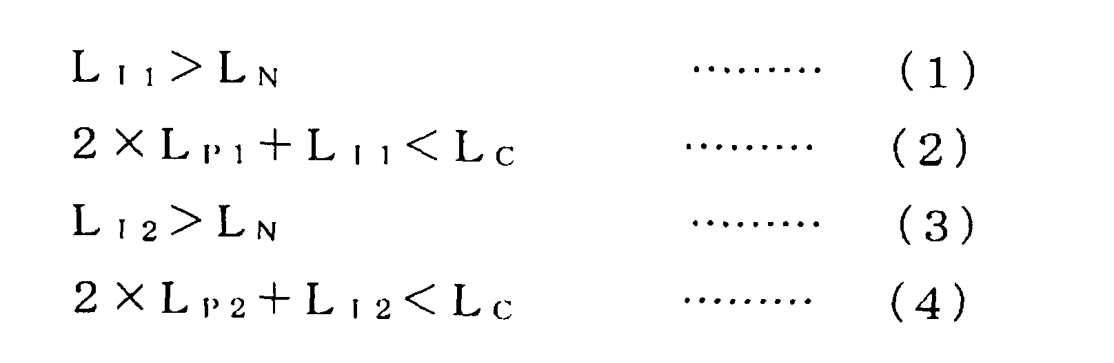
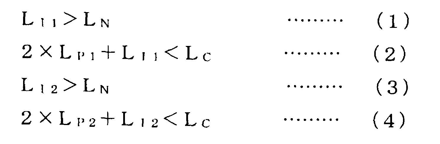
- the length of the predetermined idle time I2 is L I2 , it is preferable to satisfy the following expressions (1) to (4).
- the expression (1) is not satisfied, the first previous packet data PD1A and the first subsequent packet data PD1B are one and the same low-frequency noise N as illustrated by the hatched portion in FIG. There is also a possibility that it will be influenced by.
- the expression (2) is not satisfied, the first previous packet data PD1A and the first subsequent packet data PD1B are too long and are different as illustrated by the hatched portion in FIG. There is also the possibility of being affected by low frequency noise.
- the expression (3) is not satisfied, the second previous packet data PD2A and the second subsequent packet data PD2B have one and the same low-frequency noise N. There is also a possibility that it will be influenced by.
- the expression (4) is not satisfied, there is a possibility that the second previous packet data PD2A and the second subsequent packet data PD2B are too long and affected by different low frequency noises. However, according to the present invention, these situations can be avoided.
- the noise-free time L C of the low-frequency noise N is about 10 ⁇ sec, so the length L P1 of one packet data PD1A, PD1B may be shorter than “5 ⁇ sec ⁇ L I1 / 2”.
- the size of one packet data PD1A and PD1B may be 64 words or more and 112 words or less, and the length L I1 of the idle time I1 is 10 words. It is good to make it about.
- the length L P2 of one packet data PD2A, PD2B may be shorter than “5 ⁇ sec-L I2 / 2”.
- the size of one packet data PD2A and PD2B may be 64 words or more and 112 words or less, and the length L I2 of the idle time I1 is 10 words. It is good to make it about.
- the length was about 36 bytes at the maximum. This length varies depending on the transfer speed, cable length, cable thickness, and noise voltage.
- the noise-free time L C is equal to or less than 200 ⁇ sec than 10 .mu.sec
- the packet data PD1A, PD1B, ... speed to be transferred is less than or equal 6.25Gbps least 1.25Gbps
- two packet data sequentially transmitted with the same content (that is, the first previous packet data PD1A and the first subsequent packet data PD1B, or the second previous packet data PD2A and the second 2, at least one packet data of the second packet data PD2B) is received by the receiving units 101 and 102 without being affected by the low-frequency noise N. Therefore, according to the present invention, the transmission cable can be used even in a thin transmission cable such as 3CFB in an environment where a lot of low-frequency noise N caused by a power source or the like is generated. Machine vision can be configured by attaching industrial digital cameras to devices.
- the low frequency noise N described above may be noise that does not occur periodically, but may be noise that occurs periodically.
- the packet data PD1A, PD1B,... Having the same contents are transmitted twice from the cameras C1 and C2 to the receiving units 101 and 102.
- the operator should be able to select.
- the present invention can be applied to the CoaXPress standard, and can be applied to a packet that transmits data in a packet other than the CoaXPress standard (for example, a device that transmits data using an Ethernet (registered trademark) cable or USB). it can.
- a packet other than the CoaXPress standard for example, a device that transmits data using an Ethernet (registered trademark) cable or USB.
- the CoaXPress standard has a bandwidth from 1.25 Gbps to 6.125 Gbps, so that the target 200 Mbps can be sufficiently achieved.
- the packetized data has a CRC (Cyclic Redundancy Check Cyclic Redundancy Check: data error can be detected but cannot be restored) code. If the error occurs, it is possible to detect garbled data by performing a CRC check.
- CRC Cyclic Redundancy Check Cyclic Redundancy Check: data error can be detected but cannot be restored
- the first camera C1 transmits the first previous packet data PD1A and the first subsequent packet data PD1B with the error detection code added thereto to the first receiving unit 101, and
- the first receiving unit 101 detects data corruption of the first previous packet data PD1A or the first subsequent packet data PD1B by checking an error detection code from the first camera C1, and data It may be configured to transmit the first previous packet data PD1A or the first subsequent packet data PD1B in which no garble is detected to the data combining unit 11.
- the second camera C2 transmits the second previous packet data PD2A and the second subsequent packet data PD2B with the error detection code added thereto to the second receiving unit 102, and
- the second receiving unit 102 detects data corruption of the second previous packet data PD2A or the second subsequent packet data PD2B by checking the error detection code from the second camera C2, and the data It may be configured to transmit the second previous packet data PD2A or the second subsequent packet data PD2B in which no garble is detected to the data combining unit 11.
- the first camera C1 captures a left-eye image
- the second camera C2 captures a right-eye image, and transmits these image signals (packet data) to the external device 2, thereby providing a parallax image. It is applicable also to the use which forms.
Landscapes
- Engineering & Computer Science (AREA)
- Multimedia (AREA)
- Signal Processing (AREA)
- Theoretical Computer Science (AREA)
- Health & Medical Sciences (AREA)
- Biomedical Technology (AREA)
- General Health & Medical Sciences (AREA)
- Quality & Reliability (AREA)
- General Engineering & Computer Science (AREA)
- General Physics & Mathematics (AREA)
- Physics & Mathematics (AREA)
- Studio Devices (AREA)
- Closed-Circuit Television Systems (AREA)
- Data Exchanges In Wide-Area Networks (AREA)
Abstract
Description
第2のカメラ(C2)からの画像信号である第2のパケットデータ(PD2)を順次受信する第2の受信部(102)と、
これらの受信部(101,102)に接続されると共に前記第1のパケットデータ(PD1)と前記第2のパケットデータ(PD2)とが交互に配置された合成データ(PDs)を作成するデータ合成部(11)と、
該データ合成部(11)に接続されると共に前記合成データ(PDs)を外部機器(2)に対して送信する送信部(12)と、
を備え、
前記合成データ(PDs)中にて連続して配置される第1のパケットデータ(PD1)は、1画面分のデータよりも小さいデータであり、
前記合成データ(PDs)中にて連続して配置される第2のパケットデータ(PD2)は、1画面分のデータよりも小さいデータであることを特徴とするマルチプレクサ(1)に関する。
前記マルチプレクサ(1)と、
を備え、
該第1のカメラ(C1)から前記第1の受信部(101)に対して送信される前記第1のパケットデータ(PD1)は、図3(a)に例示するように、第1の前パケットデータ(PD1A)と、該第1の前パケットデータ(PD1A)と同じ内容であって該第1の前パケットデータ(PD1A)が送信された後に所定のアイドル時間(I1)を空けて送信される第1の後パケットデータ(PD1B)と、により構成され、
前記第2のカメラ(C2)から前記第2の受信部(102)に対して送信される前記第2のパケットデータ(PD2)は、図3(b)に例示するように、第2の前パケットデータ(PD2A)と、該第2の前パケットデータ(PD2A)と同じ内容であって該第2の前パケットデータ(PD2A)が送信された後に所定のアイドル時間(I2)を空けて送信される第2の後パケットデータ(PD2B)と、により構成され、
10μsec以上の間隔で発生するノイズ(図3(a)(b)の符号N参照。以下、“低周波ノイズ”とする)の時間幅をLNとし、1つの低周波ノイズ(N)が発生してから次の低周波ノイズ(N)が発生するまでの間の低周波ノイズ無しの時間(以下、“ノイズ無し時間”とする)をLCとし、前記第1の前パケットデータ(PD1A)及び前記第1の後パケットデータ(PD1B)の長さをLP1とし、該第1の前パケットデータ(PD1A)が送信されてから該第1の後パケットデータ(PD1B)が送信されるまでの前記所定のアイドル時間(I1)の長さをLI1とし、前記第2の前パケットデータ(PD2A)及び前記第2の後パケットデータ(PD2B)の長さをLP2とし、該第2の前パケットデータ(PD2A)が送信されてから該第2の後パケットデータ(PD2B)が送信されるまでの前記所定のアイドル時間(I2)の長さをLI2とした場合に、下式(1)~(4)を満足することを特徴とする撮影装置(3)に関する。
前記第2のカメラ(C2)は、エラー検出用コードを付加した状態の前記第2の前パケットデータ(PD2A)及び前記第2の後パケットデータ(PD2B)を前記第2の受信部(102)に送信し、
前記第1の受信部(101)は、前記第1のカメラ(C1)からのエラー検出用コードをチェックすることにより前記第1の前パケットデータ(PD1A)又は前記第1の後パケットデータ(PD1B)のデータ化けを検出すると共に、データ化けが検出されなかった方の前記第1の前パケットデータ(PD1A)又は前記第1の後パケットデータ(PD1B)を前記データ合成部(11)に送信し、
前記第2の受信部(102)は、前記第2のカメラ(C2)からのエラー検出用コードをチェックすることにより前記第2の前パケットデータ(PD2A)又は前記第2の後パケットデータ(PD2B)のデータ化けを検出すると共に、データ化けが検出されなかった方の前記第2の前パケットデータ(PD2A)又は前記第2の後パケットデータ(PD2B)を前記データ合成部(11)に送信することを特徴とする。
・ 第1のカメラC1からの画像信号(以下、“第1のパケットデータ”とする)PD1を順次受信する第1の受信部101と、
・ 第2のカメラC2からの画像信号(以下、“第2のパケットデータ“とする)PD2を順次受信する第2の受信部102と、
・ これらの受信部101,102に接続されると共に該受信部101,102からのパケットデータPD1,PD2を合成して合成データPDsを作成するデータ合成部11と、
・ 該データ合成部11に接続されると共に前記合成データPDsを外部機器2に対して送信する送信部12と、
を備えている。そして、前記データ合成部11により作成される合成データPDsは、図2(c)に例示するように、前記第1のパケットデータPD1と前記第2のパケットデータPD2とが交互に配置されたものであって、1つの該第1のパケットデータPD1(つまり、前記合成データPDs中にて連続して配置される第1のパケットデータPD1)は、1画面分のデータよりも小さいデータであり、1つの該第2のパケットデータPD2(つまり、前記合成データPDs中にて連続して配置される第2のパケットデータPD2)は、1画面分のデータよりも小さいデータであるように設定されている。具体的には、該1つの第1のパケットデータPD1や該1つの第2のパケットデータPD2は、1つの画素の画像データにすると良い。つまり、図2(a)に例示するように、前記第1のカメラC1から前記第1の受信部101に順次送信されてくる画像データ(つまり、画素毎の画像データ)をPD11,PD12,PD13,…とし、図2(b)に例示するように、前記第2のカメラC2から前記第2の受信部102に順次送信されてくる画像データ(つまり、画素毎の画像データ)をPD21,PD22,PD23,…とした場合に、前記合成データPDsは、図2(c)に例示するように、PD11,PD21,PD12,PD22,PD13,PD23,…で構成されるようにすると良い。また、該1つの第1のパケットデータPD1や該1つの第2のパケットデータPD2は、複数の画素の画像データにしても良い。さらには、該1つの第1のパケットデータPD1や該1つの第2のパケットデータPD2は、1つのラインの画像データにしても良い。またさらに、該1つの第1のパケットデータPD1や該1つの第2のパケットデータPD2は、複数のラインの画像データにしても良い。
・ 前記第1の受信部101が受信した前記第1のパケットデータPD1
・ 前記第2の受信部102が受信した前記第2のパケットデータPD2
のいずれか一方又は両方を順次保存するデータ保存部110を有するようにしても良い。
・ 第1のカメラC1と、
・ 第2のカメラC2と、
・ 上述したマルチプレクサ1と、
を備えるようにすると良い。そして、上述した第1のパケットデータPD1(つまり、前記第1のカメラC1から前記第1の受信部101に対して送信される該第1のパケットデータPD1)を、図3(a)に例示するように、同じ内容の2つのパケットデータPD1A,PD1Bにより構成し、一方のパケットデータ(以下、“第1の前パケットデータ”とする)PD1Aが送信された後に所定のアイドル時間I1を空けてもう一方のパケットデータ(以下、“第1の後パケットデータ”とする)PD1Bが送信されるようにすると良い。また、上述した第2のパケットデータPD2(つまり、前記第2のカメラC2から前記第2の受信部102に対して送信される該第2のパケットデータPD2)を、図3(b)に例示するように、同じ内容の2つのパケットデータPD2A,PD2Bにより構成し、一方のパケットデータ(以下、“第2の前パケットデータ”とする)PD2Aが送信された後に所定のアイドル時間I2を空けてもう一方のパケットデータ(以下、“第2の後パケットデータ”とする)PD2Bが送信されるようにすると良い。そして、10μsec以上の間隔で発生するノイズ(以下、“低周波ノイズ”とする)Nの時間幅をLNとし、1つの低周波ノイズNが発生してから次の低周波ノイズNが発生するまでの間の低周波ノイズ無しの時間(以下、“ノイズ無し時間”とする)をLCとし、前記第1の前パケットデータPD1A及び前記第1の後パケットデータPD1Bの長さをLP1とし、該第1の前パケットデータPD1Aが送信されてから該第1の後パケットデータPD1Bが送信されるまでの前記所定のアイドル時間I1の長さをLI1とし、前記第2の前パケットデータPD2A及び前記第2の後パケットデータPD2Bの長さをLP2とし、該第2の前パケットデータPD2Aが送信されてから該第2の後パケットデータPD2Bが送信されるまでの前記所定のアイドル時間I2の長さをLI2とした場合に、下式(1)~(4)を満足するようにすると良い。
・ 上述のようなCRCコードや、
・ 該CRCコードのようにエラーを検出するためのコード
をパケットデータに付加しておく必要がある。すなわち、前記第1のカメラC1は、エラー検出用コードを付加した状態の前記第1の前パケットデータPD1A及び前記第1の後パケットデータPD1Bを前記第1の受信部101に送信し、前記第1の受信部101は、前記第1のカメラC1からのエラー検出用コードをチェックすることにより前記第1の前パケットデータPD1A又は前記第1の後パケットデータPD1Bのデータ化けを検出すると共に、データ化けが検出されなかった方の前記第1の前パケットデータPD1A又は前記第1の後パケットデータPD1Bを前記データ合成部11に送信するように構成すると良い。また、前記第2のカメラC2は、エラー検出用コードを付加した状態の前記第2の前パケットデータPD2A及び前記第2の後パケットデータPD2Bを前記第2の受信部102に送信し、前記第2の受信部102は、前記第2のカメラC2からのエラー検出用コードをチェックすることにより前記第2の前パケットデータPD2A又は前記第2の後パケットデータPD2Bのデータ化けを検出すると共に、データ化けが検出されなかった方の前記第2の前パケットデータPD2A又は前記第2の後パケットデータPD2Bを前記データ合成部11に送信するように構成すると良い。
2 外部機器
3 撮影装置
11 データ合成部
12 送信部
101 第1の受信部
102 第2の受信部
110 データ保存部
C1 第1のカメラ
C2 第2のカメラ
I1,I2 アイドル時間
N 低周波ノイズ
PD1 第1のパケットデータ
PD1A 第1の前パケットデータ
PD1B 第1の後パケットデータ
PD2 第2のパケットデータ
PD2A 第2の前パケットデータ
PD2B 第2の後パケットデータ
PDs 合成データ
Claims (5)
- 第1のカメラからの画像信号である第1のパケットデータを順次受信する第1の受信部と、
第2のカメラからの画像信号である第2のパケットデータを順次受信する第2の受信部と、
これらの受信部に接続されると共に前記第1のパケットデータと前記第2のパケットデータとが交互に配置された合成データを作成するデータ合成部と、
該データ合成部に接続されると共に前記合成データを外部機器に対して送信する送信部と、
を備え、
前記合成データ中にて連続して配置される第1のパケットデータは、1画面分のデータよりも小さいデータであり、
前記合成データ中にて連続して配置される第2のパケットデータは、1画面分のデータよりも小さいデータである、
ことを特徴とするマルチプレクサ。 - 前記合成データ中にて連続して配置される第1のパケットデータ、及び前記合成データ中にて連続して配置される第2のパケットデータは、1つの画素、複数の画素、1つのライン又は複数のラインの画像データである、
ことを特徴とする請求項1に記載のマルチプレクサ。 - 前記データ合成部は、前記第1の受信部が受信した前記第1のパケットデータ、及び/又は前記第2の受信部が受信した前記第2のパケットデータを順次保存するデータ保存部を有する、
ことを特徴とする請求項1に記載のマルチプレクサ。 - 第1のカメラ及び第2のカメラと、
請求項1に記載のマルチプレクサと、
を備え、
該第1のカメラから前記第1の受信部に対して送信される前記第1のパケットデータは、第1の前パケットデータと、該第1の前パケットデータと同じ内容であって該第1の前パケットデータが送信された後に所定のアイドル時間を空けて送信される第1の後パケットデータと、により構成され、
前記第2のカメラから前記第2の受信部に対して送信される前記第2のパケットデータは、第2の前パケットデータと、該第2の前パケットデータと同じ内容であって該第2の前パケットデータが送信された後に所定のアイドル時間を空けて送信される第2の後パケットデータと、により構成され、
10μsec以上の間隔で発生するノイズ(以下、“低周波ノイズ”とする)の時間幅をLNとし、1つの低周波ノイズが発生してから次の低周波ノイズが発生するまでの間の低周波ノイズ無しの時間(以下、“ノイズ無し時間”とする)をLCとし、前記第1の前パケットデータ及び前記第1の後パケットデータの長さをLP1とし、該第1の前パケットデータが送信されてから該第1の後パケットデータが送信されるまでの前記所定のアイドル時間の長さをLI1とし、前記第2の前パケットデータ及び前記第2の後パケットデータの長さをLP2とし、該第2の前パケットデータが送信されてから該第2の後パケットデータが送信されるまでの前記所定のアイドル時間の長さをLI2とした場合に、下式(1)~(4)を満足する、
ことを特徴とする撮影装置。

- 前記第1のカメラは、エラー検出用コードを付加した状態の前記第1の前パケットデータ及び前記第1の後パケットデータを前記第1の受信部に送信し、
前記第2のカメラは、エラー検出用コードを付加した状態の前記第2の前パケットデータ及び前記第2の後パケットデータを前記第2の受信部に送信し、
前記第1の受信部は、前記第1のカメラからのエラー検出用コードをチェックすることにより前記第1の前パケットデータ又は前記第1の後パケットデータのデータ化けを検出すると共に、データ化けが検出されなかった方の前記第1の前パケットデータ又は前記第1の後パケットデータを前記データ合成部に送信し、
前記第2の受信部は、前記第2のカメラからのエラー検出用コードをチェックすることにより前記第2の前パケットデータ又は前記第2の後パケットデータのデータ化けを検出すると共に、データ化けが検出されなかった方の前記第2の前パケットデータ又は前記第2の後パケットデータを前記データ合成部に送信する、
ことを特徴とする請求項4に記載の撮影装置。
Priority Applications (4)
| Application Number | Priority Date | Filing Date | Title |
|---|---|---|---|
| US16/092,015 US10469799B2 (en) | 2016-04-22 | 2017-04-21 | Multiplexer and image capturing device provided with said multiplexer |
| CN201780023026.XA CN109076162B (zh) | 2016-04-22 | 2017-04-21 | 具备复用器的拍摄装置 |
| JP2018513220A JP6993323B2 (ja) | 2016-04-22 | 2017-04-21 | マルチプレクサ、及び該マルチプレクサを備えた撮影装置 |
| EP17786043.4A EP3448015B1 (en) | 2016-04-22 | 2017-04-21 | Image capturing device provided with multiplexer |
Applications Claiming Priority (2)
| Application Number | Priority Date | Filing Date | Title |
|---|---|---|---|
| JP2016086017 | 2016-04-22 | ||
| JP2016-086017 | 2016-04-22 |
Publications (1)
| Publication Number | Publication Date |
|---|---|
| WO2017183706A1 true WO2017183706A1 (ja) | 2017-10-26 |
Family
ID=60116876
Family Applications (1)
| Application Number | Title | Priority Date | Filing Date |
|---|---|---|---|
| PCT/JP2017/015967 Ceased WO2017183706A1 (ja) | 2016-04-22 | 2017-04-21 | マルチプレクサ、及び該マルチプレクサを備えた撮影装置 |
Country Status (6)
| Country | Link |
|---|---|
| US (1) | US10469799B2 (ja) |
| EP (1) | EP3448015B1 (ja) |
| JP (1) | JP6993323B2 (ja) |
| CN (1) | CN109076162B (ja) |
| TW (1) | TWI726091B (ja) |
| WO (1) | WO2017183706A1 (ja) |
Cited By (2)
| Publication number | Priority date | Publication date | Assignee | Title |
|---|---|---|---|---|
| WO2022091741A1 (ja) | 2020-10-29 | 2022-05-05 | 興和株式会社 | マルチプレクサ及び撮像システム |
| WO2024117148A1 (ja) | 2022-11-30 | 2024-06-06 | 興和株式会社 | マルチプレクサ |
Citations (4)
| Publication number | Priority date | Publication date | Assignee | Title |
|---|---|---|---|---|
| JP2006121394A (ja) * | 2004-10-21 | 2006-05-11 | Matsushita Electric Ind Co Ltd | 無線通信装置及び無線通信システム |
| JP2007036957A (ja) * | 2005-07-29 | 2007-02-08 | Auto Network Gijutsu Kenkyusho:Kk | 通信システム |
| JP2007228258A (ja) * | 2006-02-23 | 2007-09-06 | Mitsubishi Electric Corp | 映像伝送システム |
| JP2009010455A (ja) * | 2007-06-26 | 2009-01-15 | Fujitsu Ltd | 送信装置、受信装置、およびプログラム |
Family Cites Families (18)
| Publication number | Priority date | Publication date | Assignee | Title |
|---|---|---|---|---|
| US4667321A (en) * | 1983-11-14 | 1987-05-19 | Tandem Computers Incorporated | Input-output multiplexer-demultiplexer communications channel |
| US5883676A (en) * | 1994-11-28 | 1999-03-16 | Sanyo Electric Company, Ltd. | Image signal outputting apparatus |
| TW432870B (en) | 1995-07-11 | 2001-05-01 | Ultrak Inc | Video multiplexer |
| JP3363673B2 (ja) * | 1995-10-03 | 2003-01-08 | 三洋電機株式会社 | 映像信号処理装置 |
| US5828293A (en) * | 1997-06-10 | 1998-10-27 | Northern Telecom Limited | Data transmission over a power line communications system |
| JP3438564B2 (ja) * | 1998-01-26 | 2003-08-18 | ソニー株式会社 | ディジタル信号多重化装置及び方法、記録媒体 |
| US6333759B1 (en) * | 1999-03-16 | 2001-12-25 | Joseph J. Mazzilli | 360 ° automobile video camera system |
| JP2000341231A (ja) * | 1999-05-25 | 2000-12-08 | Canon Inc | 多重化装置、方法及びコンピュータ読み取り可能な記憶媒体 |
| TW441208B (en) * | 1999-09-27 | 2001-06-16 | Rf Link Systems Inc | Device and method for asynchronous time-division multiplexing access electric signal transmission |
| GB2372742A (en) * | 2001-03-03 | 2002-09-04 | Univ Leiden | C2,5'-Disubstituted and N6,C2,5'-trisubstituted adenosine derivatives and their different uses |
| US20040075741A1 (en) * | 2002-10-17 | 2004-04-22 | Berkey Thomas F. | Multiple camera image multiplexer |
| JP2010109529A (ja) * | 2008-10-29 | 2010-05-13 | Renesas Technology Corp | 多重化制御装置 |
| JP4653844B2 (ja) | 2009-07-08 | 2011-03-16 | ファナック株式会社 | ロボットシステムのための画像処理装置及びこれを備えるロボットシステム |
| DE102010003226A1 (de) * | 2010-03-24 | 2011-09-29 | Cube Optics Ag | Multiplexer/Demultiplexer mit Justierspiegel |
| US9413985B2 (en) * | 2012-09-12 | 2016-08-09 | Lattice Semiconductor Corporation | Combining video and audio streams utilizing pixel repetition bandwidth |
| JP6041697B2 (ja) * | 2013-02-15 | 2016-12-14 | 三菱重工業株式会社 | 制御装置及び産業機械 |
| CN103347144B (zh) * | 2013-07-01 | 2016-08-24 | 广东威创视讯科技股份有限公司 | 一种基于摄像头拍摄的视频同步方法 |
| US9967446B2 (en) * | 2015-09-09 | 2018-05-08 | Itx-M2M Co., Ltd. | Personalized shopping mall system using virtual camera |
-
2017
- 2017-04-21 EP EP17786043.4A patent/EP3448015B1/en active Active
- 2017-04-21 US US16/092,015 patent/US10469799B2/en active Active
- 2017-04-21 WO PCT/JP2017/015967 patent/WO2017183706A1/ja not_active Ceased
- 2017-04-21 JP JP2018513220A patent/JP6993323B2/ja active Active
- 2017-04-21 TW TW106113358A patent/TWI726091B/zh active
- 2017-04-21 CN CN201780023026.XA patent/CN109076162B/zh active Active
Patent Citations (4)
| Publication number | Priority date | Publication date | Assignee | Title |
|---|---|---|---|---|
| JP2006121394A (ja) * | 2004-10-21 | 2006-05-11 | Matsushita Electric Ind Co Ltd | 無線通信装置及び無線通信システム |
| JP2007036957A (ja) * | 2005-07-29 | 2007-02-08 | Auto Network Gijutsu Kenkyusho:Kk | 通信システム |
| JP2007228258A (ja) * | 2006-02-23 | 2007-09-06 | Mitsubishi Electric Corp | 映像伝送システム |
| JP2009010455A (ja) * | 2007-06-26 | 2009-01-15 | Fujitsu Ltd | 送信装置、受信装置、およびプログラム |
Non-Patent Citations (1)
| Title |
|---|
| See also references of EP3448015A4 * |
Cited By (6)
| Publication number | Priority date | Publication date | Assignee | Title |
|---|---|---|---|---|
| WO2022091741A1 (ja) | 2020-10-29 | 2022-05-05 | 興和株式会社 | マルチプレクサ及び撮像システム |
| JPWO2022091741A1 (ja) * | 2020-10-29 | 2022-05-05 | ||
| US12500682B2 (en) | 2020-10-29 | 2025-12-16 | Kowa Company Ltd. | Multiplexer and imaging system |
| JP7789010B2 (ja) | 2020-10-29 | 2025-12-19 | 興和株式会社 | マルチプレクサ及び撮像システム |
| WO2024117148A1 (ja) | 2022-11-30 | 2024-06-06 | 興和株式会社 | マルチプレクサ |
| EP4629607A1 (en) | 2022-11-30 | 2025-10-08 | Kowa Company, Ltd. | Multiplexer |
Also Published As
| Publication number | Publication date |
|---|---|
| JPWO2017183706A1 (ja) | 2019-02-28 |
| TWI726091B (zh) | 2021-05-01 |
| US10469799B2 (en) | 2019-11-05 |
| EP3448015B1 (en) | 2021-11-24 |
| JP6993323B2 (ja) | 2022-01-13 |
| US20190124293A1 (en) | 2019-04-25 |
| TW201739240A (zh) | 2017-11-01 |
| CN109076162B (zh) | 2020-09-22 |
| EP3448015A1 (en) | 2019-02-27 |
| CN109076162A (zh) | 2018-12-21 |
| EP3448015A4 (en) | 2019-11-27 |
Similar Documents
| Publication | Publication Date | Title |
|---|---|---|
| US20130021530A1 (en) | Transmitting device, receiving system, communication system, transmission method, reception method, and program | |
| US9903825B2 (en) | X-ray fluoroscopic radiographing apparatus and method | |
| EP2373037B1 (en) | Video transmission device, video reception device, and video communication system | |
| US7881433B2 (en) | Display control apparatus, radiation imaging apparatus, and radiation imaging system | |
| JP2007143113A (ja) | 送受信システム、送信装置、および送信方法 | |
| WO2017183706A1 (ja) | マルチプレクサ、及び該マルチプレクサを備えた撮影装置 | |
| JP2016192595A (ja) | 映像送信装置、映像受信装置、映像送信方法、映像伝送方法および映像伝送システム | |
| US9697328B2 (en) | Transmission apparatus, transmission method, reception apparatus, reception method, and computer program | |
| JP6635936B2 (ja) | パケットデータ送信装置、及びパケットデータ送信方法 | |
| JP5588244B2 (ja) | 映像伝送システム | |
| US10469727B2 (en) | Imaging apparatus, imaging method, and imaging system | |
| JP5404587B2 (ja) | 撮影装置、放射線撮影システム及び制御方法 | |
| US7298397B2 (en) | Digital transmission system | |
| HK1263209A1 (en) | Image capturing device provided with multiplexer | |
| HK1263209B (en) | Image capturing device provided with multiplexer | |
| JP7224310B2 (ja) | ネットワークシステム | |
| JP2010193045A (ja) | 無線データ伝送方法及び無線データ送受信装置 | |
| JP5649635B2 (ja) | 装置、放射線撮影システム、及び制御方法 | |
| JP6878213B2 (ja) | 映像伝送システム及びその制御方法並びにプログラム | |
| JP2012182712A (ja) | 撮像装置 | |
| JP6107119B2 (ja) | 画像データ転送システム | |
| JP5925245B2 (ja) | 装置、x線撮影システム、制御方法及びプログラム | |
| JP7354884B2 (ja) | X線動画撮影システム及びx線動画撮影方法 | |
| JP6853060B2 (ja) | 映像信号伝送装置 | |
| JP2017212544A (ja) | 制御装置、制御方法及びプログラム |
Legal Events
| Date | Code | Title | Description |
|---|---|---|---|
| WWE | Wipo information: entry into national phase |
Ref document number: 2018513220 Country of ref document: JP |
|
| NENP | Non-entry into the national phase |
Ref country code: DE |
|
| WWE | Wipo information: entry into national phase |
Ref document number: 2017786043 Country of ref document: EP |
|
| ENP | Entry into the national phase |
Ref document number: 2017786043 Country of ref document: EP Effective date: 20181122 |
|
| 121 | Ep: the epo has been informed by wipo that ep was designated in this application |
Ref document number: 17786043 Country of ref document: EP Kind code of ref document: A1 |