WO2017183399A1 - 内燃機関のフィルタ再生制御システム及び内燃機関のフィルタ再生制御方法 - Google Patents
内燃機関のフィルタ再生制御システム及び内燃機関のフィルタ再生制御方法 Download PDFInfo
- Publication number
- WO2017183399A1 WO2017183399A1 PCT/JP2017/012482 JP2017012482W WO2017183399A1 WO 2017183399 A1 WO2017183399 A1 WO 2017183399A1 JP 2017012482 W JP2017012482 W JP 2017012482W WO 2017183399 A1 WO2017183399 A1 WO 2017183399A1
- Authority
- WO
- WIPO (PCT)
- Prior art keywords
- regeneration
- internal combustion
- combustion engine
- rotational speed
- filter
- Prior art date
- Legal status (The legal status is an assumption and is not a legal conclusion. Google has not performed a legal analysis and makes no representation as to the accuracy of the status listed.)
- Ceased
Links
Images



Classifications
-
- E—FIXED CONSTRUCTIONS
- E02—HYDRAULIC ENGINEERING; FOUNDATIONS; SOIL SHIFTING
- E02F—DREDGING; SOIL-SHIFTING
- E02F9/00—Component parts of dredgers or soil-shifting machines, not restricted to one of the kinds covered by groups E02F3/00 - E02F7/00
-
- E—FIXED CONSTRUCTIONS
- E02—HYDRAULIC ENGINEERING; FOUNDATIONS; SOIL SHIFTING
- E02F—DREDGING; SOIL-SHIFTING
- E02F9/00—Component parts of dredgers or soil-shifting machines, not restricted to one of the kinds covered by groups E02F3/00 - E02F7/00
- E02F9/08—Superstructures; Supports for superstructures
- E02F9/0858—Arrangement of component parts installed on superstructures not otherwise provided for, e.g. electric components, fenders, air-conditioning units
- E02F9/0866—Engine compartment, e.g. heat exchangers, exhaust filters, cooling devices, silencers, mufflers, position of hydraulic pumps in the engine compartment
-
- F—MECHANICAL ENGINEERING; LIGHTING; HEATING; WEAPONS; BLASTING
- F01—MACHINES OR ENGINES IN GENERAL; ENGINE PLANTS IN GENERAL; STEAM ENGINES
- F01N—GAS-FLOW SILENCERS OR EXHAUST APPARATUS FOR MACHINES OR ENGINES IN GENERAL; GAS-FLOW SILENCERS OR EXHAUST APPARATUS FOR INTERNAL-COMBUSTION ENGINES
- F01N3/00—Exhaust or silencing apparatus having means for purifying, rendering innocuous, or otherwise treating exhaust
- F01N3/02—Exhaust or silencing apparatus having means for purifying, rendering innocuous, or otherwise treating exhaust for cooling, or for removing solid constituents of, exhaust
- F01N3/021—Exhaust or silencing apparatus having means for purifying, rendering innocuous, or otherwise treating exhaust for cooling, or for removing solid constituents of, exhaust by means of filters
- F01N3/023—Exhaust or silencing apparatus having means for purifying, rendering innocuous, or otherwise treating exhaust for cooling, or for removing solid constituents of, exhaust by means of filters using means for regenerating the filters, e.g. by burning trapped particles
-
- F—MECHANICAL ENGINEERING; LIGHTING; HEATING; WEAPONS; BLASTING
- F01—MACHINES OR ENGINES IN GENERAL; ENGINE PLANTS IN GENERAL; STEAM ENGINES
- F01N—GAS-FLOW SILENCERS OR EXHAUST APPARATUS FOR MACHINES OR ENGINES IN GENERAL; GAS-FLOW SILENCERS OR EXHAUST APPARATUS FOR INTERNAL-COMBUSTION ENGINES
- F01N3/00—Exhaust or silencing apparatus having means for purifying, rendering innocuous, or otherwise treating exhaust
- F01N3/02—Exhaust or silencing apparatus having means for purifying, rendering innocuous, or otherwise treating exhaust for cooling, or for removing solid constituents of, exhaust
- F01N3/021—Exhaust or silencing apparatus having means for purifying, rendering innocuous, or otherwise treating exhaust for cooling, or for removing solid constituents of, exhaust by means of filters
- F01N3/023—Exhaust or silencing apparatus having means for purifying, rendering innocuous, or otherwise treating exhaust for cooling, or for removing solid constituents of, exhaust by means of filters using means for regenerating the filters, e.g. by burning trapped particles
- F01N3/025—Exhaust or silencing apparatus having means for purifying, rendering innocuous, or otherwise treating exhaust for cooling, or for removing solid constituents of, exhaust by means of filters using means for regenerating the filters, e.g. by burning trapped particles using fuel burner or by adding fuel to exhaust
-
- F—MECHANICAL ENGINEERING; LIGHTING; HEATING; WEAPONS; BLASTING
- F01—MACHINES OR ENGINES IN GENERAL; ENGINE PLANTS IN GENERAL; STEAM ENGINES
- F01N—GAS-FLOW SILENCERS OR EXHAUST APPARATUS FOR MACHINES OR ENGINES IN GENERAL; GAS-FLOW SILENCERS OR EXHAUST APPARATUS FOR INTERNAL-COMBUSTION ENGINES
- F01N3/00—Exhaust or silencing apparatus having means for purifying, rendering innocuous, or otherwise treating exhaust
- F01N3/02—Exhaust or silencing apparatus having means for purifying, rendering innocuous, or otherwise treating exhaust for cooling, or for removing solid constituents of, exhaust
- F01N3/021—Exhaust or silencing apparatus having means for purifying, rendering innocuous, or otherwise treating exhaust for cooling, or for removing solid constituents of, exhaust by means of filters
- F01N3/033—Exhaust or silencing apparatus having means for purifying, rendering innocuous, or otherwise treating exhaust for cooling, or for removing solid constituents of, exhaust by means of filters in combination with other devices
- F01N3/035—Exhaust or silencing apparatus having means for purifying, rendering innocuous, or otherwise treating exhaust for cooling, or for removing solid constituents of, exhaust by means of filters in combination with other devices with catalytic reactors
-
- F—MECHANICAL ENGINEERING; LIGHTING; HEATING; WEAPONS; BLASTING
- F01—MACHINES OR ENGINES IN GENERAL; ENGINE PLANTS IN GENERAL; STEAM ENGINES
- F01N—GAS-FLOW SILENCERS OR EXHAUST APPARATUS FOR MACHINES OR ENGINES IN GENERAL; GAS-FLOW SILENCERS OR EXHAUST APPARATUS FOR INTERNAL-COMBUSTION ENGINES
- F01N3/00—Exhaust or silencing apparatus having means for purifying, rendering innocuous, or otherwise treating exhaust
- F01N3/08—Exhaust or silencing apparatus having means for purifying, rendering innocuous, or otherwise treating exhaust for rendering innocuous
- F01N3/10—Exhaust or silencing apparatus having means for purifying, rendering innocuous, or otherwise treating exhaust for rendering innocuous by thermal or catalytic conversion of noxious components of exhaust
- F01N3/24—Exhaust or silencing apparatus having means for purifying, rendering innocuous, or otherwise treating exhaust for rendering innocuous by thermal or catalytic conversion of noxious components of exhaust characterised by constructional aspects of converting apparatus
-
- F—MECHANICAL ENGINEERING; LIGHTING; HEATING; WEAPONS; BLASTING
- F01—MACHINES OR ENGINES IN GENERAL; ENGINE PLANTS IN GENERAL; STEAM ENGINES
- F01N—GAS-FLOW SILENCERS OR EXHAUST APPARATUS FOR MACHINES OR ENGINES IN GENERAL; GAS-FLOW SILENCERS OR EXHAUST APPARATUS FOR INTERNAL-COMBUSTION ENGINES
- F01N9/00—Electrical control of exhaust gas treating apparatus
- F01N9/002—Electrical control of exhaust gas treating apparatus of filter regeneration
-
- F—MECHANICAL ENGINEERING; LIGHTING; HEATING; WEAPONS; BLASTING
- F02—COMBUSTION ENGINES; HOT-GAS OR COMBUSTION-PRODUCT ENGINE PLANTS
- F02D—CONTROLLING COMBUSTION ENGINES
- F02D29/00—Controlling engines, such controlling being peculiar to the devices driven thereby, the devices being other than parts or accessories essential to engine operation, e.g. controlling of engines by signals external thereto
-
- F—MECHANICAL ENGINEERING; LIGHTING; HEATING; WEAPONS; BLASTING
- F02—COMBUSTION ENGINES; HOT-GAS OR COMBUSTION-PRODUCT ENGINE PLANTS
- F02D—CONTROLLING COMBUSTION ENGINES
- F02D29/00—Controlling engines, such controlling being peculiar to the devices driven thereby, the devices being other than parts or accessories essential to engine operation, e.g. controlling of engines by signals external thereto
- F02D29/04—Controlling engines, such controlling being peculiar to the devices driven thereby, the devices being other than parts or accessories essential to engine operation, e.g. controlling of engines by signals external thereto peculiar to engines driving pumps
-
- F—MECHANICAL ENGINEERING; LIGHTING; HEATING; WEAPONS; BLASTING
- F02—COMBUSTION ENGINES; HOT-GAS OR COMBUSTION-PRODUCT ENGINE PLANTS
- F02D—CONTROLLING COMBUSTION ENGINES
- F02D41/00—Electrical control of supply of combustible mixture or its constituents
- F02D41/02—Circuit arrangements for generating control signals
- F02D41/021—Introducing corrections for particular conditions exterior to the engine
- F02D41/0235—Introducing corrections for particular conditions exterior to the engine in relation with the state of the exhaust gas treating apparatus
- F02D41/024—Introducing corrections for particular conditions exterior to the engine in relation with the state of the exhaust gas treating apparatus to increase temperature of the exhaust gas treating apparatus
- F02D41/0245—Introducing corrections for particular conditions exterior to the engine in relation with the state of the exhaust gas treating apparatus to increase temperature of the exhaust gas treating apparatus by increasing temperature of the exhaust gas leaving the engine
-
- F—MECHANICAL ENGINEERING; LIGHTING; HEATING; WEAPONS; BLASTING
- F02—COMBUSTION ENGINES; HOT-GAS OR COMBUSTION-PRODUCT ENGINE PLANTS
- F02D—CONTROLLING COMBUSTION ENGINES
- F02D41/00—Electrical control of supply of combustible mixture or its constituents
- F02D41/02—Circuit arrangements for generating control signals
- F02D41/021—Introducing corrections for particular conditions exterior to the engine
- F02D41/0235—Introducing corrections for particular conditions exterior to the engine in relation with the state of the exhaust gas treating apparatus
- F02D41/027—Introducing corrections for particular conditions exterior to the engine in relation with the state of the exhaust gas treating apparatus to purge or regenerate the exhaust gas treating apparatus
- F02D41/029—Introducing corrections for particular conditions exterior to the engine in relation with the state of the exhaust gas treating apparatus to purge or regenerate the exhaust gas treating apparatus the exhaust gas treating apparatus being a particulate filter
-
- F—MECHANICAL ENGINEERING; LIGHTING; HEATING; WEAPONS; BLASTING
- F02—COMBUSTION ENGINES; HOT-GAS OR COMBUSTION-PRODUCT ENGINE PLANTS
- F02D—CONTROLLING COMBUSTION ENGINES
- F02D41/00—Electrical control of supply of combustible mixture or its constituents
- F02D41/02—Circuit arrangements for generating control signals
- F02D41/021—Introducing corrections for particular conditions exterior to the engine
- F02D41/0235—Introducing corrections for particular conditions exterior to the engine in relation with the state of the exhaust gas treating apparatus
- F02D41/024—Introducing corrections for particular conditions exterior to the engine in relation with the state of the exhaust gas treating apparatus to increase temperature of the exhaust gas treating apparatus
- F02D2041/026—Introducing corrections for particular conditions exterior to the engine in relation with the state of the exhaust gas treating apparatus to increase temperature of the exhaust gas treating apparatus using an external load, e.g. by increasing generator load or by changing the gear ratio
-
- F—MECHANICAL ENGINEERING; LIGHTING; HEATING; WEAPONS; BLASTING
- F02—COMBUSTION ENGINES; HOT-GAS OR COMBUSTION-PRODUCT ENGINE PLANTS
- F02D—CONTROLLING COMBUSTION ENGINES
- F02D2200/00—Input parameters for engine control
- F02D2200/02—Input parameters for engine control the parameters being related to the engine
- F02D2200/08—Exhaust gas treatment apparatus parameters
- F02D2200/0812—Particle filter loading
-
- F—MECHANICAL ENGINEERING; LIGHTING; HEATING; WEAPONS; BLASTING
- F02—COMBUSTION ENGINES; HOT-GAS OR COMBUSTION-PRODUCT ENGINE PLANTS
- F02D—CONTROLLING COMBUSTION ENGINES
- F02D2200/00—Input parameters for engine control
- F02D2200/60—Input parameters for engine control said parameters being related to the driver demands or status
- F02D2200/604—Engine control mode selected by driver, e.g. to manually start particle filter regeneration or to select driving style
Definitions
- the present invention relates to an internal combustion engine filter regeneration control system and an internal combustion engine filter regeneration control method.
- a vehicle equipped with a diesel engine (internal combustion engine) as a power source is a DPF (Diesel Particulate) for collecting PM (Particulate Matter), which is particulate matter contained in the exhaust gas, on the exhaust path. It has a particle collection filter called Filter.
- DPF Diesel Particulate
- Filter particle collection filter
- This fuel is combusted, that is, oxidized by the oxidation catalyst upstream of the DPF, that is, the oxidation catalyst activated in the above-described process (2), and the exhaust gas heated to high temperature by the reaction heat of the oxidation catalyst is introduced into the DPF.
- Manual regeneration is processing in which execution is started by a predetermined operation by the operator's intention when the amount of PM deposition in the DPF exceeds the automatic regeneration accumulation range.
- manual regeneration normal use of the internal combustion engine is prohibited, and only incineration by combustion of PM in the DPF is performed. In the case of a work vehicle, work cannot be performed while manual regeneration is being executed. For example, when the control device of the internal combustion engine determines that the PM accumulation amount in the DPF exceeds the automatic regeneration accumulation range, the manual regeneration is performed by displaying a display device that prompts execution of the manual regeneration. Prompt the worker.
- the worker moves the work vehicle to a safe place, puts the internal combustion engine in an idling state, and performs a predetermined operation, for example, an operation of a manual regeneration button, to start manual regeneration.
- a predetermined operation for example, an operation of a manual regeneration button
- the control device Upon recognizing a predetermined operation from the operator, the control device performs the above-described processes (1) to (3) for increasing the idling speed of the internal combustion engine, shifting to the combustion mode, and injecting fuel from the addition valve.
- the PM accumulated in is burned by combustion.
- Automatic regeneration is a process in which execution is automatically started regardless of the operator's intention when the amount of PM deposition in the DPF is within the automatic regeneration deposition range.
- incineration by combustion of PM accumulated in the DPF is automatically performed in parallel with the use of the internal combustion engine.
- the worker can perform work using the internal combustion engine except for “part of work”.
- the control device of the internal combustion engine starts automatic regeneration regardless of the operator's intention when the PM regeneration amount in the DPF is within the automatic regeneration deposition range, and when the automatic regeneration execution condition is satisfied, the above processing is performed.
- (1)-(3) The internal combustion engine idle speed UP, combustion mode transition, fuel injection from the addition valve are performed, and PM accumulated in the DPF is incinerated by combustion.
- Patent Document 1 discloses an exhaust gas purification system for a work vehicle that performs DPF regeneration processing.
- the display device prompts the operator to execute the regeneration process of the DPF.
- the operator operates the manual regeneration start switch, operates the engine control dial so as to be a low idle command, and disables the generation of control pilot pressure by the remote control valve of the gate lock lever.
- the DPF regeneration process is started. Even during manual regeneration, the operator can forcibly terminate manual regeneration and enable work by operating the gate lock lever to the working position (first position). .
- the DPF regeneration process takes a relatively long time from the start of the regeneration process until the PM accumulated in the DPF becomes less than a predetermined amount and the regeneration process is completed. .
- manual regeneration of the DPF is performed as disclosed in Patent Document 1
- work by the work vehicle is completely prohibited during the regeneration process.
- the waiting time until the regeneration process ends is a heavy burden on the driver of the work vehicle. That is, work efficiency is greatly reduced.
- the work is prioritized over the manual regeneration, and the manual regeneration is interrupted to enable the work.
- the interrupted manual regeneration process has to be performed again from the beginning after the work is finished, the burden on the driver of the work vehicle is large.
- An object of the present invention is to enable an operator to perform a low-load operation without trouble in an automatic regeneration process of a DPF that collects particulate matter in exhaust gas of an internal combustion engine without being aware of the automatic regeneration.
- An internal combustion engine filter regeneration control system and an internal combustion engine filter regeneration control method are provided. According to the system and method, it is possible to achieve both automatic regeneration of the DPF not depending on the operator's intention and work based on the operator's intention, and suppress a decrease in work efficiency.
- An internal combustion engine filter regeneration control system includes an internal combustion engine, a hydraulic pump, a work machine, a work machine operation unit, an operation lock unit, a particle collection filter, a deposition amount detection unit, a catalyst, a target rotation speed instruction unit, a regeneration process execution unit, And a control device.
- the hydraulic pump is driven by the internal combustion engine.
- the working machine is operated by hydraulic pressure by hydraulic oil discharged from the hydraulic pump.
- the work machine operation unit is operated to operate the work machine.
- the operation lock unit can switch whether the operation instruction from the work implement operation unit is valid or invalid.
- the particle collection filter collects particulate matter contained in exhaust gas from the internal combustion engine.
- the accumulation amount detection unit detects an accumulation amount of particulate matter deposited on the particle collection filter.
- the catalyst is provided in an exhaust path from the internal combustion engine to the particle collection filter.
- the target rotational speed instruction unit instructs a target rotational speed of the internal combustion engine.
- the regeneration process execution unit executes a filter regeneration process in which the temperature of the exhaust gas flowing into the particle collection filter is increased and the particulate matter collected by the particle collection filter is incinerated by combustion. It is configured.
- the control device is configured to control operations of the internal combustion engine and the regeneration processing execution unit.
- the control device stores a regeneration lower limit rotational speed that is preset as a lower limit rotational speed of the internal combustion engine during execution of the filter regeneration processing.
- the controller is configured to start execution of automatic regeneration when it is determined that the particulate matter deposition amount detected by the deposition amount detector exceeds a regeneration start threshold threshold value.
- the control device is configured to control the internal combustion engine in a filter regeneration combustion mode in which the temperature of exhaust gas discharged from the internal combustion engine is increased.
- the control device is configured to control the rotational speed of the internal combustion engine to the designated target rotational speed when the directed target rotational speed instructed from the target rotational speed instruction section is equal to or greater than the regeneration lower limit rotational speed. ing.
- the control device sets the rotational speed of the internal combustion engine to the designated target rotational speed or the regeneration lower limit depending on the state of the operation lock unit. It is configured to control by switching to one of the rotation speeds.
- the control device is configured to control the regeneration processing execution unit so that the filter regeneration processing is performed according to the temperature of the catalyst.
- the second aspect of the present invention provides a filter regeneration control method for an internal combustion engine applied to a filter regeneration control system.
- a filter regeneration control system includes an internal combustion engine, a hydraulic pump, a work machine, a work machine operation unit, an operation lock unit, a particle collection filter, a deposition amount detection unit, a catalyst, a target rotation speed instruction unit, a regeneration process execution unit, and a control device.
- the hydraulic pump is driven by the internal combustion engine.
- the working machine is operated by hydraulic pressure by hydraulic oil discharged from the hydraulic pump.
- the work machine operation unit is operated to operate the work machine.
- the operation lock unit can switch whether the operation instruction from the work implement operation unit is valid or invalid.
- the particle collection filter collects particulate matter contained in exhaust gas from the internal combustion engine.
- the accumulation amount detection unit detects an accumulation amount of particulate matter deposited on the particle collection filter.
- the catalyst is provided in an exhaust path from the internal combustion engine to the particle collection filter.
- the target rotational speed instruction unit instructs a target rotational speed of the internal combustion engine.
- the regeneration process execution unit executes a filter regeneration process in which the temperature of the exhaust gas flowing into the particle collection filter is increased and the particulate matter collected by the particle collection filter is incinerated by combustion. It is configured.
- the control device is configured to control operations of the internal combustion engine and the regeneration processing execution unit.
- the control device stores a regeneration lower limit rotational speed that is preset as a lower limit rotational speed of the internal combustion engine during execution of the filter regeneration processing.
- the filter regeneration control method includes a combustion mode changing step, a rotation speed switching step, and a particulate matter combustion incineration step.
- the combustion mode changing step the temperature of the exhaust gas discharged from the internal combustion engine is controlled using the control device when the accumulation amount of the particulate matter detected by the accumulation amount detection unit exceeds a regeneration start threshold value.
- the internal combustion engine is controlled in a combustion mode for increasing the filter regeneration.
- the rotational speed switching step when the command target rotational speed instructed from the target rotational speed instruction section is equal to or higher than the regeneration lower limit rotational speed using the control device, the rotational speed of the internal combustion engine is set to the designated target speed.
- the rotation speed of the internal combustion engine is set to the instruction target rotation speed or the regeneration rotation speed according to the state of the operation lock unit. Switch to one of the lower limit speeds to control.
- the particulate matter combustion incineration step uses the control device to control the regeneration processing execution unit so that the filter regeneration processing is performed according to the temperature of the catalyst.
- FIG. 5 is a conceptual diagram of an operating region of the internal combustion engine in each case in the rotational speed and shaft torque characteristics of the internal combustion engine.
- the work vehicle 80 includes a construction machine and an industrial vehicle.
- the work vehicle 80 includes a lower traveling body 81 having a crawler, an upper turning body 82, a boom 83, an arm 84, and a bucket 85.
- the crawler of the lower traveling body 81 and the upper turning body 82 are operated by power from a hydraulic motor (not shown).
- the boom 83 is operated by the hydraulic cylinder 83C
- the arm 84 is operated by the hydraulic cylinder 84C
- the bucket 85 is operated by the hydraulic cylinder 85C.
- the operator operates a work machine operation unit provided in the cockpit to travel using the crawler of the lower traveling body 81, rotate the upper revolving body 82, boom 83, arm 84, and bucket 85. Can be operated.
- the crawler, the upper swing body 82, the boom 83, the arm 84, and the bucket 85 that are operated by hydraulic pressure correspond to a working machine. ⁇ [Work vehicle control system configuration (Fig. 2)] FIG.
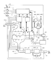
- FIG. 2 shows a configuration of a work vehicle control system that controls work vehicle 80 shown in FIG.
- the control method for an internal combustion engine of the present invention is applied to the work vehicle control system.
- a hybrid-type work vehicle control system that drives the hydraulic pump 31 using the diesel engine 11 (corresponding to an internal combustion engine) and the electric motor 21 will be described as an example.
- a work vehicle control system that omits and drives the hydraulic pump 31 only by the diesel engine 11 may be used.
- the diesel engine 11 is controlled by the engine controller 10, the electric motor 21 is controlled by the motor controller 20, and the hydraulic pump 31 is controlled by the machine controller 30.
- the engine controller 10, the motor controller 20, and the machine controller 30 correspond to a control device.
- the control device group is configured by three control devices (the engine controller 10, the motor controller 20, and the body controller 30), but the control device group may be configured by one control device, or 2
- the control device group may be configured by one or four or more control devices.
- the body controller 30 and the engine controller 10 can transmit and receive various information via the communication line T13, and the body controller 30 and the motor controller 20 can transmit and receive various information via the communication line T23.
- the rotor 21C of the electric motor 21 is connected to the crankshaft 11C of the diesel engine 11, and the rotor 31C of the hydraulic pump 31 is connected to the rotor 21C of the electric motor 21.
- the hydraulic pump 31 uses at least one of the diesel engine 11 and the electric motor 21 as a power source, sucks the hydraulic oil in the tank 32 through the pipe 33, and discharges the hydraulic oil to the pipe 34.
- the hydraulic motor 51 and the hydraulic cylinders 83C, 84C, and 85C are connected to the pipe 34 via the work machine operation unit 50.
- the hydraulic motor 51 drives the crawler and the upper swing body.
- a relief valve 36 is connected to the pipe 34.
- the relief valve 36 is connected to the tank 32 via a pipe 37.
- the relief valve 36 is in the closed state, the hydraulic oil in the pipe 34 is supplied to the hydraulic motor 51 and the hydraulic cylinders 83C, 84C, and 85C via the work machine operation unit 50.
- the relief valve 36 is in an open state, the hydraulic oil in the pipe 34 is returned to the tank 32 via the relief valve 36 and the pipe 37 without passing through the work machine operation unit 50.
- the operator can switch the relief valve 36 between the open state and the closed state by operating the operation lock portion 41.
- the operation lock unit 41 validates the operation from the work machine operation unit 50 used when the operator operates the work machine (sets the relief valve 36 in a closed state) or invalidates the relief machine 36 (relieving the relief valve 36). Can be switched).
- the diesel engine 11 is connected to an intake path constituted by an intake pipe 11A and an intake manifold 11B, and is connected to an exhaust path constituted by an exhaust manifold 11E and an exhaust pipe 11F.
- a throttle device 18 is provided in the intake path.
- the engine controller 10 can control the throttle device 18 to adjust the amount of air taken in by the diesel engine 11.
- a turbocharger having a variable nozzle and an EGR pipe and an EGR valve for returning a part of the exhaust gas to the downstream side of the throttle device 18 are also provided.
- the engine controller 10 can control the turbocharger variable nozzle to adjust the boost pressure of intake air, and can control the EGR valve to adjust the EGR amount.
- each cylinder of the diesel engine 11 is provided with an injector for injecting fuel.
- the injector supplies an appropriate amount of fuel to each cylinder at an appropriate timing based on a drive signal from the engine controller 10.
- the diesel engine 11 includes a crank rotation detection unit (rotation sensor) that outputs a detection signal corresponding to the rotation of the crankshaft 11C, and a cylinder detection unit (a cylinder detection unit that outputs a cylinder discrimination signal indicating that a specific cylinder is in the compression process).
- Various detection units (sensors) such as a cylinder discrimination sensor) and a cooling water temperature detection unit (water temperature sensor) are attached, and description and description thereof are omitted.
- a fuel addition valve 15, exhaust temperature detectors 16A, 16B, and 16C, a catalyst 12, a particle collection filter 13, a differential pressure detector 17, and an A / F detector 14 are provided in the exhaust path.
- the catalyst 12 and the particle collection filter 13 may be integrated as a filter unit without being configured separately.
- the differential pressure detector 17 may be assembled so as to be integrated in one case.
- the fuel addition valve 15 (corresponding to the regeneration processing execution unit) is provided on the upstream side of the catalyst 12 (and the particle collection filter 13), and burns the particulate matter collected in the particle collection filter 13. Is controlled by the engine controller 10 during incineration, and fuel is injected into the exhaust path.
- the fuel injected from the fuel addition valve 15 is used for combustion in the activated catalyst 12 (catalyst such as an oxidation catalyst), that is, oxidation, and becomes high temperature by the reaction heat of the catalyst 12, that is, the oxidation reaction heat.
- Exhaust gas is introduced into the particle collection filter 13, and the particulate matter deposited in the particle collection filter 13 is incinerated by combustion.
- the exhaust temperature detection units 16A, 16B, and 16C are, for example, exhaust temperature sensors, and the exhaust temperature detection unit 16A is provided upstream of the catalyst 12, that is, at the inlet of the catalyst 12.
- the exhaust temperature detector 16B is provided between the catalyst 12 and the particle collecting filter 13, that is, at the outlet of the catalyst 12 or the inlet of the particle collecting filter 13.
- the exhaust temperature detector 16C is provided downstream of the particle collection filter 13, that is, at the outlet of the particle collection filter 13.
- the engine controller 10 can know the temperature of the exhaust gas at each position in the exhaust path based on detection signals from the exhaust temperature detection units 16A, 16B, and 16C. Note that the number and positions of the exhaust temperature detection units are not limited to the numbers and positions shown in the example of FIG.
- the A / F detector 14 is an A / F sensor, for example, and outputs a detection signal related to the air-fuel ratio of the exhaust gas.
- the engine controller 10 knows the air-fuel ratio based on the detection signal from the A / F detector 14 and adjusts the fuel injection amount from the injector based on the air-fuel ratio.
- the catalyst 12 purifies predetermined components (for example, CO (carbon monoxide), HC (hydrocarbon)) in the exhaust gas and renders them harmless.
- the particle collecting filter 13 is a DPF (Diesel Particulate Filter) and collects particulate matter contained in the exhaust gas.
- the differential pressure detection unit 17 is, for example, a differential pressure sensor, and is connected to the upstream side and the downstream side of the particle collection filter 13.
- the differential pressure detection unit 17 corresponds to a deposition amount detection unit.
- the engine controller 10 can know the differential pressure between the upstream pressure and the downstream pressure of the particle collection filter 13 based on the detection signal from the differential pressure detection unit 17, and the particle collection filter 13. It is possible to estimate the amount of particulate matter that has been collected and collected.
- the engine controller 10 has a storage device such as a CPU and a memory. In addition to the detection signals from the exhaust temperature detectors 16A, 16B, and 16C, the differential pressure detector 17, the crank rotation detector, and the cylinder detector, the engine controller 10 includes various detectors (not shown). Detection signal is input. The engine controller 10 outputs drive signals for driving various actuators (not shown) in addition to the throttle device 18, the fuel addition valve 15, and the injector described above. Further, the engine controller 10 controls the diesel engine 11 based on the requested torque information (engine target rotation) received from the machine controller 30 via the communication line T13.
- a storage device such as a CPU and a memory.
- the engine controller 10 includes various detectors (not shown). Detection signal is input.
- the engine controller 10 outputs drive signals for driving various actuators (not shown) in addition to the throttle device 18, the fuel addition valve 15, and the injector described above. Further, the engine controller 10 controls the diesel engine 11 based on the requested torque information (engine target rotation) received from the machine controller 30
- the motor controller 20 has a storage device such as a CPU and a memory.
- the motor controller 20 detects the rotation state of the rotor 21C based on a detection signal from a rotor rotation detection unit (for example, a rotor rotation sensor) that detects the rotation state of the rotor 21C of the electric motor 21, and sets the detected rotation state. Based on this, the current to each coil of the stator is controlled.
- the motor controller 20 controls the electric motor 21 based on the requested torque information (motor target rotation) received from the machine controller 30 via the communication line T23.
- the machine controller 30 has a CPU and a storage device such as a memory.
- the body controller 30 receives detection signals from the operation lock unit 41, the engine control dial 42, the regeneration inhibition unit 43, the manual regeneration execution unit 44, and the like, and receives a hydraulic load detection signal from the hydraulic pump 31 (not shown).
- the engine control dial 42 corresponds to a target rotational speed instruction unit.
- the operation lock unit 41 switches the relief valve 36 between an open state and a closed state by an operation from the operator.
- the engine control dial 42 outputs a detection signal based on the target rotational speed of the diesel engine 11 instructed by the operator to the machine controller 30.
- the regeneration prohibiting unit 43 is a regeneration prohibiting switch for prohibiting the execution of the filter regeneration processing, for example.
- the manual regeneration execution unit 44 is a manual regeneration execution switch for instructing execution of manual regeneration in the filter regeneration process, for example.
- the airframe controller 30 obtains the required torque for the diesel engine 11 and the electric motor 21 based on each input described above, transmits the required torque information (engine target rotation) to the engine controller 10 via the communication line T12, and performs communication. Requested torque information (motor target rotation) is transmitted to the motor controller 20 via the line T23.
- the engine controller 10 starts the process of the engine controller shown in FIG. 3 at a predetermined timing at predetermined time intervals (for example, every several tens [ms]), and advances the process to step S110.
- step S110 the engine controller 10 estimates the PM deposition amount (particulate matter deposition amount) in the particle collection filter, and proceeds to step S115.
- the engine controller 10 estimates the PM accumulation amount based on the differential pressure detected using the differential pressure detection unit 17 (corresponding to the accumulation amount detection unit).
- step S115 the engine controller 10 determines whether or not the estimated PM accumulation amount exceeds a regeneration start threshold value (deposition amount at which automatic regeneration is to be started). If the regeneration start threshold value is exceeded (Yes), step S115 is performed. The process proceeds to S120, and if the reproduction start threshold is not exceeded (No), the process proceeds to Step S190.
- the regeneration start threshold value is stored in advance in the storage device of the engine controller 10.
- step S120 the engine controller 10 determines whether or not the regeneration prohibiting unit 43 operated by the operator is ON, and the regeneration prohibiting unit 43 is ON (instructed to prohibit the filter regeneration process). ) (Yes), the process proceeds to step S180. When the regeneration prohibiting unit 43 is OFF (permission of filter regeneration processing is instructed) (No), the process proceeds to step S130. Note that the ON or OFF state of the reproduction prohibition unit 43 is appropriately received from the machine controller 30 via the communication line T13.
- Steps S130 to S150A and S150B and steps S310 to S340 and S420A described later are automatic reproduction processes.
- the engine controller 10 sets the regeneration combustion mode flag to ON and proceeds to step S135.
- the regeneration combustion mode flag is a flag used in the processing shown in FIG. 5 described later, and in order to activate the catalyst 12 as the filter regeneration combustion mode during the automatic regeneration, This is a flag used to intentionally increase the combustion temperature.
- step S135 the engine controller 10 transmits the lower limit rotational speed for reproduction to the machine controller 30 via the communication line T13, and proceeds to step S140.
- the regeneration lower limit rotational speed is stored in advance in the storage device of the engine controller 10 as the lower limit rotational speed of the internal combustion engine during execution of automatic regeneration.
- the engine controller 10 reads the reproduction lower limit rotational speed (for example, 500 [rpm]) stored in advance in the storage device, and transmits the reproduction lower limit rotational speed to the machine controller 30.
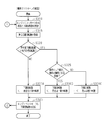
- the machine controller 30 activates the process of the machine controller shown in FIG. 4 at the timing when information is received from the engine controller 10 via the communication line T13, for example, and proceeds to step S310.
- step S310 body controller 30 receives the lower limit rotational speed for regeneration from engine controller 10, and proceeds to step S315.
- step S315 the body controller 30 acquires the indicated target rotational speed (the rotational speed of the internal combustion engine desired by the worker) designated from the engine control dial 42 operated by the worker, and proceeds to step S320.
- step S320 body controller 30 determines whether or not the designated target rotational speed is less than the lower limit rotational speed for reproduction. If the designated target rotational speed is less than the lower rotational speed for reproduction (Yes), step S325 is performed. If the instruction target rotational speed is equal to or higher than the reproduction lower limit rotational speed (No), the process proceeds to step S330A.
- step S325 the body controller 30 determines whether or not the operation lock unit 41 operated by the worker is in a state of invalidating the operation instruction from the work unit operating unit operated by the worker. If the operation instruction is invalidated (Yes), the process proceeds to step S330B. If the operation instruction is valid (No), the process proceeds to step S330C.
- step S325 when the automatic target regeneration is being executed and the command target rotational speed, which is the target rotational speed instructed from the engine control dial (target rotational speed instruction section), is less than the regeneration lower limit rotational speed, This corresponds to a rotation speed switching step in which the lower limit rotation speed is switched to either the indicated target rotation speed or the reproduction lower limit rotation speed in accordance with the state of the operation lock unit.
- the body controller 30 sets the lower limit rotation speed to the lower limit rotation speed for reproduction (substitutes the lower limit rotation speed for reproduction into the lower limit rotation speed), and proceeds to step S340.
- Step S330B the body controller 30 sets the lower limit rotational speed to the lower limit rotational speed for reproduction (substitutes the lower limit rotational speed for reproduction into the lower limit rotational speed), and proceeds to step S340.
- Step S330B is when the operation lock unit is in a state of invalidating the operation instruction (from the work machine operation unit) when the instruction target rotation speed is less than the lower limit rotation speed for reproduction during execution of automatic regeneration.
- the lower limit rotational speed is switched to the lower limit rotational speed for reproduction.
- Step S330C the aircraft controller 30 sets the lower limit rotation speed to the command target rotation speed (substitutes the command target rotation speed for the lower limit rotation speed), and proceeds to step S340.
- Step S330C is when the operation lock unit is in a state of validating the operation instruction (from the work implement operation unit) when the instruction target rotation speed is less than the lower limit rotation speed for reproduction during execution of automatic regeneration.
- the lower limit rotational speed is switched to the indicated target rotational speed, which is a feature of the present application.
- step S340 body controller 30 transmits the lower limit rotational speed to engine controller 10 and ends the process.
- step S140 the engine controller receives the lower limit rotational speed from the body controller 30, and proceeds to step S145.
- the engine controller 10 controls the rotational speed of the internal combustion engine during execution of automatic regeneration based on the received lower limit rotational speed.
- the engine controller 10 controls the rotational speed of the internal combustion engine so as to be the indicated target rotational speed when the designated target rotational speed instructed from the engine control dial 42 is equal to or higher than the lower limit rotational speed during execution of the automatic regeneration.
- the rotational speed of the internal combustion engine is controlled to be the lower limit rotational speed.
- step S145 the engine controller 10 estimates the temperature of the catalyst 12 based on detection signals from the exhaust gas temperature detection units 16A, 16B, and 16C, and the estimated catalyst temperature is equal to or higher than a preset catalyst activation temperature. If the temperature is equal to or higher than the catalyst activation temperature (Yes), the process proceeds to step S150A. If the temperature is lower than the catalyst activation temperature (No), the process proceeds to step S150B.
- the catalyst activation temperature is stored in advance in the storage device of the engine controller 10.
- step S150A the engine controller 10 controls the fuel addition valve 15 (corresponding to the regeneration process execution unit) to incinerate (filter regeneration process) by burning particulate matter accumulated in the particle collection filter. ) Injects a predetermined amount of fuel necessary for the process, and ends the process. Since the regeneration combustion mode flag is set to ON in step S130, steps S150A and S150B are performed when the processing of the combustion mode changing step (step S420A described later) is being executed (during execution of automatic regeneration). Will be executed.
- step S150B the engine controller 10 stops the fuel injection from the fuel addition valve 15 and ends the process.
- the lower limit rotational speed is less than the regeneration lower limit rotational speed
- the exhaust gas flow rate may be insufficient and the catalyst temperature may not reach the activation temperature.
- the temperature of the catalyst does not reach the activation temperature, a sufficient oxidation reaction cannot be performed with the catalyst. Therefore, when the catalyst is activated by the processing of steps S145, S150A, and S150B, the fuel is appropriately Fuel is injected from the addition valve. Further, the processes of steps S145 and S150B are not “interruption” but “temporary hold” of automatic regeneration. If the catalyst temperature becomes equal to or higher than the catalyst activation temperature, fuel injection from the fuel addition valve is immediately performed.
- steps S145, S150A, and S150B control the fuel addition valve (corresponding to the regeneration process execution unit) so that the filter regeneration process (incineration by burning particulate matter) is performed according to the temperature of the catalyst.
- the filter regeneration process incineration by burning particulate matter
- step S180 the engine controller 10 executes a process when the regeneration prohibiting unit is ON (it is an existing process and a description thereof is omitted), and the process proceeds to step S190.
- the routine proceeds to step S190, the engine controller 10 turns off the regeneration combustion mode flag and ends the process.
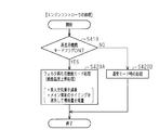
- the engine controller 10 starts the process of the engine controller shown in FIG. 5 at a predetermined timing such as a predetermined time interval (for example, every several tens [ms]), and advances the process to step S410.
- a predetermined timing such as a predetermined time interval (for example, every several tens [ms])
- a predetermined time interval for example, every several tens [ms]
- step S410 the engine controller 10 determines whether or not the regeneration combustion mode flag is ON. If the regeneration combustion mode flag is ON (Yes), the process proceeds to step S420A, where the regeneration combustion mode flag is set. If it is OFF (No), the process proceeds to step S420B.
- step S420A the engine controller 10 executes the filter regeneration combustion mode process and ends the process.
- the engine controller 10 increases the combustion temperature of the internal combustion engine and increases the temperature of the exhaust gas in order to activate the catalyst 12 when burning the particulate matter accumulated in the particle collection filter by combustion. .
- the engine controller 10 throttles the throttle device 18 slightly to reduce the intake air amount.
- the engine controller 10 slightly increases the injection amount by slightly delaying the injection timing of the fuel injection from the injector that injects fuel into each cylinder of the diesel engine 11, that is, delaying the main injection timing. Thereby, the combustion temperature of the diesel engine 11 can be raised.
- the process of step S420A corresponds to a combustion mode changing step of controlling the internal combustion engine in a filter regeneration combustion mode that raises the combustion temperature of the internal combustion engine during execution of automatic regeneration.
- step S420B the engine controller 10 executes the process in the normal mode and ends the process. Specifically, the process in the normal mode is not to perform the process performed in step S420A.
- the engine controller 10 returns to the opening degree when it is normal, that is, when not in the filter regeneration combustion mode, without performing the process of reducing the throttle device 18, and the timing and the injection amount of the main injection are normal, that is, not in the filter regeneration combustion mode. Return to the main injection timing and injection amount.
- Region A shows a medium / high load region where the rotational speed of the internal combustion engine is equal to or higher than the lower limit rotational speed for regeneration
- region C is a low load where the rotational speed of the internal combustion engine is equal to or higher than the low idle rotational speed and lower than the lower limit rotational speed for regeneration. Indicates the area.
- the rotation speed of the internal combustion engine is as shown in FIG. 6 is maintained at the “low idle speed” shown in the upper diagram.
- the rotational speed of the internal combustion engine is changed from “low idle rotational speed” to “ Increased to “reduction lower limit speed”.
- the lower limit rotational speed for regeneration is set to a rotational speed that can secure the flow rate of exhaust gas necessary for burning the particulate matter accumulated in the particle collecting filter by combustion.
- the temperature of the exhaust gas is raised and the catalyst is activated. can do. If the catalyst is activated, as described above, the fuel is injected from the fuel addition valve so that the fuel is burned, that is, oxidized, and the exhaust gas that has been heated by the reaction heat is introduced into the particle collection filter. Then, the particulate matter accumulated in the particle collecting filter can be incinerated by combustion.
- the flow rate of the exhaust gas discharged from the internal combustion engine is a sufficient flow rate to activate the catalyst, and the combustion mode for filter regeneration
- the catalyst can be easily activated, that is, heated to a temperature higher than the catalyst activation temperature. If the catalyst is activated, as described above, the particulate matter accumulated in the particle collection filter can be incinerated by combustion by injecting the fuel from the fuel addition valve. Further, in the case where the operation is performed in the region C in the upper diagram of FIG. 6, the flow rate of the exhaust gas discharged from the internal combustion engine is insufficient to activate the catalyst.
- the catalyst temperature may be lowered and not activated even when the combustion mode for filter regeneration is entered.
- the catalyst is not activated, as described above, the fuel injection from the fuel addition valve is stopped, and the filter regeneration process, that is, the incineration due to the combustion of the particulate matter is temporarily suspended while maintaining the automatic regeneration. To do.
- the operation lock unit since the operation lock unit is in a state in which the operation is invalidated, it is detected by the control device that the operator has no intention to work. Therefore, even if the engine control dial indicates a rotational speed less than the regeneration lower limit rotational speed, the idle speed of the internal combustion engine is raised to the regeneration lower limit rotational speed by the control device. For this reason, the flow rate of the exhaust gas discharged from the internal combustion engine is a flow rate sufficient for activating the catalyst.
- the catalyst By setting the combustion mode for filter regeneration, the catalyst is easily activated, that is, the catalyst activation temperature. The temperature can be raised to the above. If the catalyst is activated, as described above, the particulate matter accumulated in the particle collection filter can be incinerated by combustion by injecting the fuel from the fuel addition valve.
- the filter regeneration process by automatic regeneration is a process that takes a relatively long time, an operator may desire to replace the cutting edge tool of the working machine during execution of this automatic regeneration.
- the end cutting tool of the work machine corresponds to the bucket 85.
- the operation lock unit In order to replace the tip cutter, an operation from the work implement operation unit is required, and therefore the operation lock unit must be in a state in which an operation instruction from the work implement operation unit is valid.
- the speed of the internal combustion engine is made lower than the regeneration lower limit speed during execution of automatic regeneration, that is, when the region C in the upper diagram of FIG. 6 is used, the exhaust gas flow rate decreases and the catalyst temperature decreases.
- the catalyst may become inactive. If the catalyst is not in an activated state, incineration by burning particulate matter in the particle collection filter may not proceed as expected. Therefore, in the present application, when the catalyst temperature becomes lower than the catalyst activation temperature during the execution of the automatic regeneration, the fuel injection from the fuel addition valve is stopped and the filter regeneration process, that is, the incineration by the combustion of the particulate matter is temporarily performed. When the catalyst temperature becomes equal to or higher than the catalyst activation temperature, the fuel regeneration from the fuel addition valve is executed and the filter regeneration process is immediately resumed.
- the internal combustion engine filter regeneration control system and internal combustion engine filter regeneration control method of the present invention are not limited to the configuration, processing procedure, and the like described in the present embodiment, and various modifications are possible without departing from the scope of the present invention. It can be changed, added and deleted.
- the filter regeneration control system for an internal combustion engine and the filter regeneration control method for an internal combustion engine described in the present embodiment can be applied to various work vehicles including construction machines and industrial vehicles.
- the differential pressure detection unit is used as an example of the accumulation amount detection unit.
- the accumulation amount detection unit is not limited to the differential pressure detection unit.
- the description “greater than” may be used instead of the description “more than” used as a comparison of values.
- the description “more than” may be used instead of the description “beyond”.
- the description “below” may be used instead of the description “less than”.
- the numerical values used in the description of the present embodiment are examples, and are not limited to these numerical values.
Landscapes
- Engineering & Computer Science (AREA)
- Chemical & Material Sciences (AREA)
- General Engineering & Computer Science (AREA)
- Combustion & Propulsion (AREA)
- Mechanical Engineering (AREA)
- Chemical Kinetics & Catalysis (AREA)
- Mining & Mineral Resources (AREA)
- Civil Engineering (AREA)
- Structural Engineering (AREA)
- Health & Medical Sciences (AREA)
- Toxicology (AREA)
- Processes For Solid Components From Exhaust (AREA)
- Component Parts Of Construction Machinery (AREA)
- Exhaust Gas After Treatment (AREA)
- Control Of Vehicle Engines Or Engines For Specific Uses (AREA)
Abstract
制御装置は、粒子状物質の堆積量が再生開始閾値を超えた場合、自動再生を開始し、自動再生の実行中は、排気ガスの温度を上昇させるフィルタ再生用燃焼モードにて内燃機関を制御し、目標回転数指示部から指示された指示目標回転数が再生用下限回転数未満である場合、内燃機関の下限回転数を、操作ロック部の状態に応じて、指示目標回転数あるいは再生用下限回転数のいずれかに切り替えて制御し、触媒の温度に応じて再生処理実行部を制御する。
Description
本発明は、内燃機関のフィルタ再生制御システム及び内燃機関のフィルタ再生制御方法に関する。
動力源としてディーゼルエンジン(内燃機関)を搭載している車両は、その排気経路上に排気ガス中に含まれている粒子状物質であるPM(Particulate Matter)を捕集するためのDPF(Diesel Particulate Filter)と呼ばれる粒子捕集フィルタを備えている。DPFに所定量以上の粒子状物質が堆積された場合、DPFの目詰まりによる排圧上昇の問題を回避するために、DPF内の粒子状物質を燃焼により焼却する、いわゆる「再生処理」が行われる。なお、再生処理では、下記の処理(1)~(3)を行うことで、DPF内に堆積しているPMが燃焼により焼却される。
(1)DPF内に堆積しているPMを燃焼によって焼却するのに必要な排気ガスの流量を確保するために、内燃機関の最低回転数の底上げ、即ちアイドル回転数UPが行われる。
(2)内燃機関の排気ガスの温度を意図的に高くして、DPFの上流に設けられた酸化触媒を活性化させるために、普段の燃料の噴射に対して、噴射のタイミングの遅延や噴射量の増量等の処理を行う、特殊な燃焼モードへと燃焼モードが移行される。
(3)エンジンから排出される排気ガスの排気経路中に設けた添加弁、即ち酸化触媒の上流に設けた添加弁から燃料が噴射される。DPF上流の酸化触媒、即ち上記処理(2)で活性化させた酸化触媒によってこの燃料を燃焼させ、即ち酸化させ、酸化触媒の反応熱で高温となった排気ガスがDPFに導入される。
(1)DPF内に堆積しているPMを燃焼によって焼却するのに必要な排気ガスの流量を確保するために、内燃機関の最低回転数の底上げ、即ちアイドル回転数UPが行われる。
(2)内燃機関の排気ガスの温度を意図的に高くして、DPFの上流に設けられた酸化触媒を活性化させるために、普段の燃料の噴射に対して、噴射のタイミングの遅延や噴射量の増量等の処理を行う、特殊な燃焼モードへと燃焼モードが移行される。
(3)エンジンから排出される排気ガスの排気経路中に設けた添加弁、即ち酸化触媒の上流に設けた添加弁から燃料が噴射される。DPF上流の酸化触媒、即ち上記処理(2)で活性化させた酸化触媒によってこの燃料を燃焼させ、即ち酸化させ、酸化触媒の反応熱で高温となった排気ガスがDPFに導入される。
また「再生処理」には、主に2通りの処理がある。1つは「手動再生」と呼ばれる処理で、もう1つは「自動再生」と呼ばれる処理である。内燃機関が運転されてDPFへのPMの堆積量が増加していくと、やがてPM堆積量は自動再生堆積範囲に達し、さらにPM堆積量が増加すると、PM堆積量は自動再生堆積範囲を超える。
手動再生は、DPF内のPM堆積量が自動再生堆積範囲を超えている場合において、作業者の意思による所定の操作によって実行が開始される処理である。手動再生では、内燃機関の通常の使用は禁止されてDPF内のPMの燃焼による焼却のみが行われる。作業車両の場合、手動再生の実行中は作業を行うことができない。例えば内燃機関の制御装置は、DPF内のPM堆積量が自動再生堆積範囲を超えていると判定した場合、手動再生の実行を督促することを示す表示装置を表示させることにより、手動再生の実行を作業者に促す。作業者は、手動再生の督促を確認すると、作業車両を安全な場所に移動し、内燃機関をアイドリング状態にして所定の操作、例えば手動再生ボタンの操作を行って、手動再生を開始させる。制御装置は、作業者からの所定の操作を認識すると、上記処理(1)~(3)の内燃機関のアイドル回転数UP、燃焼モードの移行、添加弁からの燃料の噴射を行い、DPF内に堆積しているPMを燃焼により焼却させる。
自動再生は、DPF内のPM堆積量が自動再生堆積範囲内にある場合において、作業者の意思にかかわらず、自動的に実行が開始される処理である。自動再生では、内燃機関の使用と並行して、DPF内に堆積しているPMの燃焼による焼却が自動的に行われる。作業車両の場合、自動再生の実行中、作業者は、「一部の作業」を除いて内燃機関を使用して作業を行うことができる。例えば内燃機関の制御装置は、DPFへのPM堆積量が自動再生堆積範囲内にあるとき、自動再生の実行条件が満足した場合に、作業者の意思にかかわらず自動再生を開始し、上記処理(1)~(3)の内燃機関のアイドル回転数UP、燃焼モードの移行、添加弁からの燃料の噴射を行い、DPF内に堆積しているPMを燃焼により焼却させる。
例えば、特許文献1には、DPFの再生処理を行う作業車両の排気ガス浄化システムが開示されている。この排気ガス浄化システムでは、DPFに堆積するPMの量が所定量以上となると表示装置により作業者にDPFの再生処理の実行を促す。排気ガス浄化システムは、作業者が手動再生開始スイッチを操作し、エンジンコントロールダイヤルをローアイドル指令となるように操作し、かつゲートロックレバーをリモコン弁による制御パイロット圧の生成を不能とするように操作したときに、DPFの再生処理を開始するようにしている。なお、手動再生中であっても、作業者は、ゲートロックレバーを作業用の位置(第1位置)に操作することで、手動再生を強制的に終了させて作業を可能にすることができる。
上記のようなDPFの再生処理(手動再生及び自動再生)は、再生処理が開始されてからDPFに堆積するPMが所定量以下となって再生処理が完了するまでに比較的長い時間を要す。特に、特許文献1に開示されているようにDPFの手動再生を行う場合には、その再生処理の実行中は作業車両による作業が全面的に禁止される。そのため、再生処理が終了するまでの待ち時間が、作業車両の運転者にとって大きな負担となる。つまり、作業効率が大きく低下する。また、特許文献1に記載の排気ガス浄化システムでは、手動再生に対して作業を優先し、手動再生を中断させて作業を可能としている。しかしながら、中断させた手動再生の処理は、作業の終了後、最初からやり直さなければならないので、作業車両の運転者にとって、負担が大きい。
手動再生が必要となるまでDPF内にPMを堆積させてしまうと、手動再生によって作業効率が大きく低下してしまうので、これを回避できる自動再生は非常に有効な手段である。近年の内燃機関の制御装置には、上記の手動再生と自動再生の双方の機能が組み込まれており、自動再生をすることで手動再生の頻度を低下させて作業効率の低下を抑制している。しかしながら、自動再生が実行されると、作業者の意思にかかわらず自動的に内燃機関の最低回転数が底上げ、即ちアイドル回転数UPされるので、内燃機関の回転数を非常に低くしなければ実施できない作業を実行することができない。内燃機関の回転数を非常に低くしなければ実施できない作業は、上記の「一部の作業」であり、以降では「低負荷作業」と記載する。例えば作業車両がパワーショベルの場合、内燃機関の回転数を非常に低い回転数にして油圧の微調整を行いながら実行する先端刃具の交換作業を行うことができない。自動再生が実行されると、作業者は、低負荷作業を除いた作業を行うことはできるが、低負荷作業については自動再生が終了するまで実行することができないので、作業効率が低下する場合がある。
特許文献1に記載されているように、作業者の意思によって自動再生を中断する手段を用意することも考えられる。しかしながら、低負荷作業を実行できない場合に、作業者はいちいち自動再生を中断させなければならないので、手間がかかる。そもそも、自動再生は作業者の意思で開始されていないので、作業者が低負荷作業を実行できない原因が自動再生であることに気付くことは困難である。
本発明の目的は、内燃機関の排気ガス中の粒子状物質を捕集するDPFの自動再生の処理において、作業者が自動再生を意識することなく手間なく低負荷作業を実行することを可能とする内燃機関のフィルタ再生制御システム及び内燃機関のフィルタ再生制御方法を提供することにある。該システム及び方法によれば、作業者の意思によらないDPFの自動再生と、作業者の意思による作業と、を両立させ、作業効率の低下を抑制することができる。
上記目的を達成するため、本発明の第1の態様は、内燃機関のフィルタ再生制御システムを提供する。内燃機関のフィルタ再生制御システムは、内燃機関、油圧ポンプ、作業機、作業機操作部、操作ロック部、粒子捕集フィルタ、堆積量検知部、触媒、目標回転数指示部、再生処理実行部、及び制御装置を備える。前記油圧ポンプは、前記内燃機関によって駆動される。前記作業機は、前記油圧ポンプから吐出される作動油による油圧によって作動される。前記作業機操作部は、前記作業機を動作させるために操作される。前記操作ロック部は、前記作業機操作部からの操作指示を有効とするか無効とするかを、切り替え可能である。前記粒子捕集フィルタは、前記内燃機関からの排気ガス中に含まれている粒子状物質を捕集する。前記堆積量検知部は、前記粒子捕集フィルタに堆積する粒子状物質の堆積量を検知する。前記触媒は、前記内燃機関から前記粒子捕集フィルタまでの排気経路に設けられている。前記目標回転数指示部は、前記内燃機関の目標回転数を指示する。前記再生処理実行部は、前記粒子捕集フィルタに流入する前記排気ガスの温度を上昇させて前記粒子捕集フィルタに捕集された粒子状物質を燃焼により焼却させるフィルタ再生処理を実行するように構成されている。前記制御装置は、前記内燃機関及び前記再生処理実行部の動作を制御するように構成されている。前記制御装置には、前記フィルタ再生処理の実行中における前記内燃機関の下限回転数として予め設定された再生用下限回転数が記憶されている。そして、前記制御装置は、前記堆積量検知部によって検知された粒子状物質の堆積量が再生開始閾閾値を超えたと判定した場合、自動再生の実行を開始するように構成されている。前記自動再生の実行中には、前記制御装置は、前記内燃機関から排出される排気ガスの温度を上昇させるフィルタ再生用燃焼モードにて前記内燃機関を制御するように構成されている。前記制御装置は、前記目標回転数指示部から指示された指示目標回転数が前記再生用下限回転数以上である場合、前記内燃機関の回転数を当該指示目標回転数に制御するように構成されている。前記制御装置は、前記指示目標回転数が前記再生用下限回転数未満である場合、前記内燃機関の回転数を、前記操作ロック部の状態に応じて、前記指示目標回転数あるいは前記再生用下限回転数のいずれかに切り替えて制御するように構成されている。前記制御装置は、前記触媒の温度に応じて、前記フィルタ再生処理が実行されるように前記再生処理実行部を制御するように構成されている。
本発明の第2の態様は、フィルタ再生制御システムに適用される内燃機関のフィルタ再生制御方法を提供する。フィルタ再生制御システムは、内燃機関、油圧ポンプ、作業機、作業機操作部、操作ロック部、粒子捕集フィルタ、堆積量検知部、触媒、目標回転数指示部、再生処理実行部、及び制御装置を備える。前記油圧ポンプは、前記内燃機関によって駆動される。前記作業機は、前記油圧ポンプから吐出される作動油による油圧によって作動される。前記作業機操作部は、前記作業機を動作させるために操作される。前記操作ロック部は、前記作業機操作部からの操作指示を有効とするか無効とするかを、切り替え可能である。前記粒子捕集フィルタは、前記内燃機関からの排気ガス中に含まれている粒子状物質を捕集する。前記堆積量検知部は、前記粒子捕集フィルタに堆積する粒子状物質の堆積量を検知する。前記触媒は、前記内燃機関から前記粒子捕集フィルタまでの排気経路に設けられている。前記目標回転数指示部は、前記内燃機関の目標回転数を指示する。前記再生処理実行部は、前記粒子捕集フィルタに流入する前記排気ガスの温度を上昇させて前記粒子捕集フィルタに捕集された粒子状物質を燃焼により焼却させるフィルタ再生処理を実行するように構成されている。前記制御装置は、前記内燃機関及び前記再生処理実行部の動作を制御するように構成されている。前記制御装置には、前記フィルタ再生処理の実行中における前記内燃機関の下限回転数として予め設定された再生用下限回転数が記憶されている。そして、フィルタ再生制御方法は、燃焼モード変更ステップ、回転数切り替えステップ、及び粒子状物質燃焼焼却ステップを備える。前記燃焼モード変更ステップは、前記堆積量検知部が検知する粒子状物質の堆積量が再生開始閾値を超えた場合に、前記制御装置を用いて、前記内燃機関から排出される排気ガスの温度を上昇させるフィルタ再生用燃焼モードにて前記内燃機関を制御する。前記回転数切り替えステップは、前記制御装置を用いて、前記目標回転数指示部から指示された指示目標回転数が前記再生用下限回転数以上である場合、前記内燃機関の回転数を当該指示目標回転数に制御し、前記指示目標回転数が前記再生用下限回転数未満である場合、前記内燃機関の回転数を、前記操作ロック部の状態に応じて、前記指示目標回転数あるいは前記再生用下限回転数のいずれかに切り替えて制御する。前記粒子状物質燃焼焼却ステップは、前記制御装置を用いて、前記触媒の温度に応じて、前記フィルタ再生処理が実行されるように前記再生処理実行部を制御する。
以下に本発明を実施するための形態を図面を用いて説明する。
●[作業車両80の外観(図1)]
以下、図1に示すパワーショベルを作業車両の例として説明する。作業車両は、建設機械や産業車両を含む。作業車両80は、クローラを有する下部走行体81、上部旋回体82、ブーム83、アーム84、及びバケット85を有している。
●[作業車両80の外観(図1)]
以下、図1に示すパワーショベルを作業車両の例として説明する。作業車両は、建設機械や産業車両を含む。作業車両80は、クローラを有する下部走行体81、上部旋回体82、ブーム83、アーム84、及びバケット85を有している。
下部走行体81のクローラや上部旋回体82は、油圧モータ(図示省略)からの動力にて動作する。ブーム83は油圧シリンダ83Cにて動作し、アーム84は油圧シリンダ84Cにて動作し、バケット85は油圧シリンダ85Cにて動作する。作業者は、操縦席に設けられた作業機操作部を操作することで、下部走行体81のクローラを用いて走行したり、上部旋回体82を旋回させたり、ブーム83やアーム84やバケット85を動作させたりすることができる。なお、油圧によって作動する上記のクローラ、上部旋回体82、ブーム83、アーム84、バケット85は、作業機に相当している。
●[作業車両制御システムの構成(図2)]
図2は、図1に示す作業車両80を制御している作業車両制御システムの構成を示している。当該作業車両制御システムには、本発明の内燃機関の制御方法が適用されている。なお、本実施の形態の説明では、ディーゼルエンジン11(内燃機関に相当)と電動モータ21とを用いて油圧ポンプ31を駆動するハイブリッド方式の作業車両制御システムを例として説明するが、電動モータを省略してディーゼルエンジン11のみにて油圧ポンプ31を駆動する方式の作業車両制御システムであってもよい。
●[作業車両制御システムの構成(図2)]
図2は、図1に示す作業車両80を制御している作業車両制御システムの構成を示している。当該作業車両制御システムには、本発明の内燃機関の制御方法が適用されている。なお、本実施の形態の説明では、ディーゼルエンジン11(内燃機関に相当)と電動モータ21とを用いて油圧ポンプ31を駆動するハイブリッド方式の作業車両制御システムを例として説明するが、電動モータを省略してディーゼルエンジン11のみにて油圧ポンプ31を駆動する方式の作業車両制御システムであってもよい。
なお、本実施の形態の例では、ディーゼルエンジン11はエンジンコントローラ10にて制御され、電動モータ21はモータコントローラ20にて制御され、油圧ポンプ31は機体コントローラ30にて制御される例を示す。エンジンコントローラ10、モータコントローラ20、及び機体コントローラ30は、制御装置に相当する。この例では、3つの制御装置(エンジンコントローラ10とモータコントローラ20と機体コントローラ30)にて制御装置群を構成しているが、1つの制御装置で制御装置群を構成してもよいし、2つあるいは4つ以上の制御装置にて制御装置群を構成してもよい。また機体コントローラ30とエンジンコントローラ10は、通信線T13を介して種々の情報を送受信可能であり、機体コントローラ30とモータコントローラ20は、通信線T23を介して種々の情報を送受信可能である。
図2に示す作業車両制御システムでは、ディーゼルエンジン11のクランクシャフト11Cに、電動モータ21のロータ21Cが接続されており、電動モータ21のロータ21Cに油圧ポンプ31のロータ31Cが接続されている。油圧ポンプ31は、ディーゼルエンジン11と電動モータ21の少なくとも一方を動力源として、配管33を介してタンク32内の作動油を吸引し、配管34へと作動油を吐出する。
配管34には、作業機操作部50を介して、油圧モータ51や、油圧シリンダ83C、84C、85Cが接続されている。油圧モータ51は、クローラや上部旋回体を駆動する。また、配管34には、リリーフバルブ36が接続されている。そしてリリーフバルブ36は配管37を介してタンク32に接続されている。リリーフバルブ36が閉鎖状態の場合、配管34内の作動油は、作業機操作部50を介して油圧モータ51や油圧シリンダ83C、84C、85Cに供給される。リリーフバルブ36が開口状態の場合、配管34内の作動油は、作業機操作部50を介することなくリリーフバルブ36と配管37を経由してタンク32に戻される。作業者は、操作ロック部41を操作することで、リリーフバルブ36の開口状態または閉鎖状態の切り替えを行うことができる。操作ロック部41は、作業者が作業機を操作する際に使用する作業機操作部50からの操作を有効とする(リリーフバルブ36を閉鎖状態とする)か、無効とする(リリーフバルブ36を開口状態とする)か、を切り替え可能である。
ディーゼルエンジン11には、吸気配管11Aと吸気マニホルド11Bにて構成された吸気経路が接続されており、排気マニホルド11Eと排気配管11Fにて構成された排気経路が接続されている。吸気経路には、スロットル装置18が設けられている。エンジンコントローラ10は、スロットル装置18を制御して、ディーゼルエンジン11が吸入する空気の量を調節することができる。また、図示省略するが、可変ノズルを備えたターボチャージャや、排気ガスの一部をスロットル装置18の下流側に戻すEGR配管とEGRバルブも有している。エンジンコントローラ10は、ターボチャージャの可変ノズルを制御して吸気の過給圧を調整可能であり、EGRバルブを制御してEGR量を調整可能である。
また、図示省略するが、ディーゼルエンジン11の各気筒には、燃料を噴射するインジェクタが設けられている。インジェクタは、エンジンコントローラ10からの駆動信号に基づいて、適切なタイミングで、適切な燃料量を、各気筒に供給する。またディーゼルエンジン11には、クランクシャフト11Cの回転に応じた検出信号を出力するクランク回転検出部(回転センサ)、特定の気筒が圧縮工程にあることを示す気筒判別信号を出力する気筒検出部(気筒判別センサ)、冷却水温度検出部(水温センサ)等、種々の検出部(センサ)が取り付けられているが、これらについては記載及び説明を省略する。
排気経路には、燃料添加弁15、排気温度検出部16A、16B、16C、触媒12、粒子捕集フィルタ13、差圧検出部17、A/F検出部14が設けられている。なお、触媒12と粒子捕集フィルタ13は、別々に構成されることなくフィルタユニットとして一体化されていてもよく、例えば、触媒12、粒子捕集フィルタ13、排気温度検出部16A、16B、16C、差圧検出部17が、1つのケース内に一体となるように組み付けられていてもよい。燃料添加弁15(再生処理実行部に相当)は、触媒12(及び粒子捕集フィルタ13)よりも上流側に設けられており、粒子捕集フィルタ13内に捕集された粒子状物質を燃焼により焼却する際にエンジンコントローラ10から制御され、排気経路内に燃料を噴射する。燃料添加弁15から噴射された燃料は、活性化された触媒12(酸化触媒等の触媒)内での燃焼、即ち酸化に使用され、触媒12の反応熱、即ち酸化反応熱で高温となった排気ガスが粒子捕集フィルタ13に導入され、当該排気ガスによって粒子捕集フィルタ13内に堆積している粒子状物質が燃焼により焼却される。排気温度検出部16A、16B、16Cは、例えば排気温度センサであり、排気温度検出部16Aは触媒12の上流、即ち触媒12の入口部に設けられている。排気温度検出部16Bは触媒12と粒子捕集フィルタ13との間、即ち触媒12の出口部または粒子捕集フィルタ13の入口部に設けられている。排気温度検出部16Cは粒子捕集フィルタ13の下流、即ち粒子捕集フィルタ13の出口部に設けられている。エンジンコントローラ10は、排気温度検出部16A、16B、16Cからの検出信号に基づいて、排気経路の各位置における排気ガスの温度を知ることができる。なお、排気温度検出部の数、及び設ける位置については、図2の例に示す数及び位置に限定されるものではない。またA/F検出部14は、例えばA/Fセンサであり、排気ガスの空燃比に関する検出信号を出力する。エンジンコントローラ10は、A/F検出部14からの検出信号に基づいて空燃比を知り、当該空燃比に基づいてインジェクタからの燃料噴射量を調整する。
触媒12は、排気ガス中の所定の成分(例えばCO(一酸化炭素)、HC(炭化水素))を浄化して無害化する。粒子捕集フィルタ13は、DPF(Diesel Particulate Filter)であり、排気ガス中に含まれている粒子状物質を捕集する。差圧検出部17は、例えば差圧センサであり、粒子捕集フィルタ13の上流側と下流側に接続されている。差圧検出部17は、堆積量検知部に相当する。エンジンコントローラ10は、差圧検出部17からの検出信号に基づいて、粒子捕集フィルタ13の上流側の圧力と下流側の圧力との差圧を知ることが可能であり、粒子捕集フィルタ13にて捕集した、堆積している粒子状物質の量を推定することができる。
エンジンコントローラ10は、CPUとメモリ等の記憶装置を有している。そしてエンジンコントローラ10には、上述した排気温度検出部16A、16B、16C、差圧検出部17、クランク回転検出部、気筒検出部からの検出信号の他にも、図示省略した種々の検出部からの検出信号が入力されている。またエンジンコントローラ10は、上述したスロットル装置18、燃料添加弁15、インジェクタの他にも、図示省略した種々のアクチュエータを駆動する駆動信号を出力している。またエンジンコントローラ10は、通信線T13を介して機体コントローラ30から受信した要求トルク情報(エンジン目標回転)に基づいて、ディーゼルエンジン11を制御する。
モータコントローラ20は、CPUとメモリ等の記憶装置を有している。そしてモータコントローラ20は、電動モータ21のロータ21Cの回転状態を検出するロータ回転検出部(例えばロータ回転センサ)からの検出信号に基づいて、ロータ21Cの回転状態を検出し、検出した回転状態に基づいて、ステータの各コイルへの電流を制御する。またモータコントローラ20は、通信線T23を介して機体コントローラ30から受信した要求トルク情報(モータ目標回転)に基づいて、電動モータ21を制御する。
機体コントローラ30は、CPUとメモリ等の記憶装置を有している。そして機体コントローラ30には、操作ロック部41、エンジンコントロールダイヤル42、再生禁止部43、手動再生実行部44等からの検出信号が入力され、図示省略した油圧ポンプ31からの油圧負荷検出信号が入力されている。エンジンコントロールダイヤル42は、目標回転数指示部に相当する。操作ロック部41は、作業者からの操作によって、リリーフバルブ36の開口状態または閉鎖状態の切り替えを行う。エンジンコントロールダイヤル42は、作業者から指示されたディーゼルエンジン11の目標回転数に基づいた検出信号を機体コントローラ30に出力する。再生禁止部43は、例えばフィルタ再生処理の実行を禁止するための再生禁止スイッチであり、作業者が再生禁止部43を操作すると、即ち再生禁止スイッチをONにすると、フィルタ再生処理の実行が禁止される。手動再生実行部44は、例えばフィルタ再生処理における手動再生の実行を指示するための手動再生実行スイッチであり、作業者が手動再生実行部を操作すると、即ち手動再生実行スイッチをONにすると、フィルタ再生処理の手動再生が実行される。機体コントローラ30は、上述した各入力に基づいて、ディーゼルエンジン11と電動モータ21への要求トルクを求め、通信線T12を介して要求トルク情報(エンジン目標回転)をエンジンコントローラ10に送信し、通信線T23を介して要求トルク情報(モータ目標回転)をモータコントローラ20に送信する。
●[制御装置(エンジンコントローラと機体コントローラ)の処理手順(図3~図5)]
次に図3~図5に示すフローチャートを用いて、制御装置(エンジンコントローラ10と機体コントローラ30)の処理について説明する。なお、手動再生については従来と同様であるので、説明を省略している。また以降の説明では、「フィルタ再生処理」、「自動再生」という言葉を、「フィルタ再生処理=粒子状物質の燃焼による焼却」、「自動再生=燃焼モードの変更+下限回転数の切り替え+フィルタ再生処理」という意味で使用する。
●[制御装置(エンジンコントローラと機体コントローラ)の処理手順(図3~図5)]
次に図3~図5に示すフローチャートを用いて、制御装置(エンジンコントローラ10と機体コントローラ30)の処理について説明する。なお、手動再生については従来と同様であるので、説明を省略している。また以降の説明では、「フィルタ再生処理」、「自動再生」という言葉を、「フィルタ再生処理=粒子状物質の燃焼による焼却」、「自動再生=燃焼モードの変更+下限回転数の切り替え+フィルタ再生処理」という意味で使用する。
まず図3に示すエンジンコントローラの処理について説明する。エンジンコントローラ10は、所定時間間隔(例えば数10[ms]毎)の所定タイミングにて、図3に示すエンジンコントローラの処理を起動し、ステップS110へと処理を進める。
ステップS110にてエンジンコントローラ10は、粒子捕集フィルタ内のPM堆積量(粒子状物質の堆積量)を推定し、ステップS115に進む。例えばエンジンコントローラ10は、差圧検出部17(堆積量検知部に相当)を用いて検出した差圧に基づいて、PM堆積量を推定する。
ステップS115にてエンジンコントローラ10は、推定したPM堆積量が再生開始閾値(自動再生を開始するべき堆積量)を超えたか否かを判定し、再生開始閾値を超えている場合(Yes)はステップS120に進み、再生開始閾値を超えていない場合(No)はステップS190に進む。再生開始閾値は、エンジンコントローラ10の記憶装置に予め記憶されている。
ステップS120に進んだ場合、エンジンコントローラ10は、作業者によって操作される再生禁止部43がONであるか否かを判定し、再生禁止部43がON(フィルタ再生処理の禁止が指示されている)である場合(Yes)はステップS180に進み、再生禁止部43がOFF(フィルタ再生処理の許可が指示されている)である場合(No)はステップS130に進む。なお、再生禁止部43のONまたはOFFの状態は、通信線T13を介して機体コントローラ30から適宜受信する。
ステップS130~ステップS150A、S150B、及び後述するステップS310~ステップS340、ステップS420Aの処理は、自動再生の処理である。ステップS130に進んだ場合、エンジンコントローラ10は、再生用燃焼モードフラグをONにして、ステップS135に進む。なお、再生用燃焼モードフラグは、後述する図5に示す処理にて使用するフラグであり、自動再生の実行中において、フィルタ再生用燃焼モードとして、触媒12を活性化するために、内燃機関の燃焼温度を意図的に上昇させるために用いるフラグである。
ステップS135にてエンジンコントローラ10は、通信線T13を介して機体コントローラ30に、再生用下限回転数を送信し、ステップS140に進む。なお、再生用下限回転数は、自動再生の実行中における内燃機関の下限回転数として、予めエンジンコントローラ10の記憶装置に記憶されている。エンジンコントローラ10は、予め記憶装置に記憶されている再生用下限回転数(例えば500[rpm])を読み出して、機体コントローラ30に再生用下限回転数を送信する。
次に図4に示す機体コントローラの処理について説明する。機体コントローラ30は、例えば通信線T13を介してエンジンコントローラ10から情報を受信したタイミングにて、図4に示す機体コントローラの処理を起動し、ステップS310へと処理を進める。
ステップS310にて機体コントローラ30は、エンジンコントローラ10から再生用下限回転数を受信し、ステップS315に進む。
ステップS315にて機体コントローラ30は、作業者によって操作されるエンジンコントロールダイヤル42から指示された指示目標回転数(作業者が所望する内燃機関の回転数)を取得し、ステップS320に進む。
ステップS315にて機体コントローラ30は、作業者によって操作されるエンジンコントロールダイヤル42から指示された指示目標回転数(作業者が所望する内燃機関の回転数)を取得し、ステップS320に進む。
ステップS320にて機体コントローラ30は、指示目標回転数が再生用下限回転数未満であるか否かを判定し、指示目標回転数が再生用下限回転数未満である場合(Yes)はステップS325に進み、指示目標回転数が再生用下限回転数以上である場合(No)はステップS330Aに進む。
ステップS325に進んだ場合、機体コントローラ30は、作業者から操作される操作ロック部41が、作業者が操作する作業機操作部からの操作指示を無効とする状態とされているか否かを判定し、操作指示を無効とする状態とされている場合(Yes)はステップS330Bに進み、操作指示を有効とする状態とされている場合(No)はステップS330Cに進む。ステップS325の処理は、自動再生の実行中において、エンジンコントロールダイヤル(目標回転数指示部)から指示された目標回転数である指示目標回転数が再生用下限回転数未満である場合、内燃機関の下限回転数を、操作ロック部の状態に応じて、指示目標回転数あるいは再生用下限回転数のいずれかに切り替える、回転数切り替えステップに相当する。
ステップS330Aに進んだ場合、機体コントローラ30は、下限回転数を再生用下限回転数に設定して(下限回転数に再生用下限回転数を代入して)ステップS340に進む。
ステップS330Bに進んだ場合、機体コントローラ30は、下限回転数を再生用下限回転数に設定して(下限回転数に再生用下限回転数を代入して)ステップS340に進む。ステップS330Bは、自動再生の実行中において、指示目標回転数が再生用下限回転数未満である際に、操作ロック部が(作業機操作部からの)操作指示を無効とする状態である場合に、下限回転数を再生用下限回転数に切り替えている。
ステップS330Cに進んだ場合、機体コントローラ30は、下限回転数を指示目標回転数に設定して(下限回転数に指示目標回転数を代入して)ステップS340に進む。ステップS330Cは、自動再生の実行中において、指示目標回転数が再生用下限回転数未満である際に、操作ロック部が(作業機操作部からの)操作指示を有効とする状態である場合に、下限回転数を指示目標回転数に切り替えており、本願の特徴となる処理である。
ステップS340にて機体コントローラ30は、エンジンコントローラ10に下限回転数を送信し、処理を終了する。
エンジンコントローラは、ステップS140にて、機体コントローラ30から下限回転数を受信し、ステップS145に進む。なお、エンジンコントローラ10は、受信した下限回転数に基づいて、自動再生の実行中における内燃機関の回転数を制御する。エンジンコントローラ10は、自動再生の実行中において、エンジンコントロールダイヤル42から指示された指示目標回転数が下限回転数以上である場合は指示目標回転数となるように内燃機関の回転数を制御し、指示目標回転数が下限回転数より低い場合は下限回転数となるように内燃機関の回転数を制御する。
エンジンコントローラは、ステップS140にて、機体コントローラ30から下限回転数を受信し、ステップS145に進む。なお、エンジンコントローラ10は、受信した下限回転数に基づいて、自動再生の実行中における内燃機関の回転数を制御する。エンジンコントローラ10は、自動再生の実行中において、エンジンコントロールダイヤル42から指示された指示目標回転数が下限回転数以上である場合は指示目標回転数となるように内燃機関の回転数を制御し、指示目標回転数が下限回転数より低い場合は下限回転数となるように内燃機関の回転数を制御する。
ステップS145にてエンジンコントローラ10は、排気温度検出部16A、16B、16Cからの検出信号に基づいて触媒12の温度を推定し、推定した触媒温度が、予め設定された触媒活性化温度以上であるか否かを判定し、触媒活性化温度以上である場合(Yes)はステップS150Aに進み、触媒活性化温度未満である場合(No)はステップS150Bに進む。触媒活性化温度は、エンジンコントローラ10の記憶装置に予め記憶されている。
ステップS150Aに進んだ場合、エンジンコントローラ10は、燃料添加弁15(再生処理実行部に相当)を制御して、粒子捕集フィルタ内に堆積している粒子状物質の燃焼による焼却(フィルタ再生処理)に必要となる所定の燃料量を噴射し、処理を終了する。なお、ステップS130にて再生用燃焼モードフラグがONとされているので、燃焼モード変更ステップ(後述するステップS420A)の処理が実行されているとき(自動再生の実行中)に、ステップS150A、S150Bが実行されることになる。
ステップS150Bに進んだ場合、エンジンコントローラ10は、燃料添加弁15からの燃料の噴射を停止して、処理を終了する。下限回転数を再生用下限回転数未満とした場合では、排気ガスの流量が不足して触媒の温度が活性化温度に達しない場合がある。触媒の温度が活性化温度に達していない場合では、触媒にて充分な酸化反応を行うことができないので、ステップS145、S150A、S150Bの処理によって、触媒が活性化している場合に、適切に燃料添加弁から燃料を噴射する。また、ステップS145、S150Bの処理は、自動再生の「中断」ではなく「一時的保留」の処理であり、触媒の温度が触媒活性化温度以上となれば、ただちに燃料添加弁からの燃料の噴射(すなわち、粒子捕集フィルタ内の粒子状物質の燃焼による焼却)を再開することができる。ステップS145、S150A、S150Bの処理は、触媒の温度に応じて、フィルタ再生処理(粒子状物質の燃焼による焼却)が実行されるように燃料添加弁(再生処理実行部に相当)を制御する、粒子状物質燃焼焼却ステップに相当している。
ステップS180に進んだ場合、エンジンコントローラ10は、再生禁止部がONの場合の処理(既存の処理であり、説明を省略する)を実行し、ステップS190に進む。
ステップS190に進んだ場合、エンジンコントローラ10は、再生用燃焼モードフラグをOFFにして、処理を終了する。
ステップS190に進んだ場合、エンジンコントローラ10は、再生用燃焼モードフラグをOFFにして、処理を終了する。
次に、図5に示すエンジンコントローラの処理について説明する。エンジンコントローラ10は、所定時間間隔(例えば数10[ms]毎)等の所定タイミングにて、図5に示すエンジンコントローラの処理を起動し、ステップS410へと処理を進める。
ステップS410にてエンジンコントローラ10は、再生用燃焼モードフラグがONであるか否かを判定し、再生用燃焼モードフラグがONである場合(Yes)はステップS420Aに進み、再生用燃焼モードフラグがOFFである場合(No)はステップS420Bに進む。
ステップS420Aに進んだ場合、エンジンコントローラ10は、フィルタ再生用燃焼モードの処理を実行して、処理を終了する。エンジンコントローラ10は、粒子捕集フィルタ内に堆積している粒子状物質を燃焼により焼却するにあたって触媒12を活性化するために、内燃機関の燃焼温度を上昇させて、排気ガスの温度を上昇させる。具体的には、エンジンコントローラ10は、スロットル装置18を少し絞って吸入空気量を減量する。あるいは、エンジンコントローラ10は、ディーゼルエンジン11の各気筒に燃料を噴射するインジェクタからの燃料噴射の噴射タイミングを少し遅らせて、即ちメイン噴射のタイミングを遅角して、噴射量を増量させる。これにより、ディーゼルエンジン11の燃焼温度を上昇させることができる。ステップS420Aの処理は、自動再生の実行中において、内燃機関の燃焼温度を上昇させるフィルタ再生用燃焼モードにて内燃機関を制御する、燃焼モード変更ステップに相当している。
ステップS420Bに進んだ場合、エンジンコントローラ10は、通常モード時の処理を実行し、処理を終了する。具体的には、ステップS420Aにて実施した処理を行わないことが通常モード時の処理である。エンジンコントローラ10は、スロットル装置18を絞る処理を行うことなく通常時、即ちフィルタ再生用燃焼モードでないときの開度に戻し、メイン噴射のタイミングも噴射量も通常時、即ちフィルタ再生用燃焼モードでないときのメイン噴射のタイミングと噴射量に戻す。
●[本願の効果(図6)]
図6に、「操作ロック部=操作を「有効」とした状態の場合、かつ、自動再生実行中の場合」における内燃機関の稼働領域(使用領域)の特性(回転数・軸トルク特性)と、「操作ロック部=操作を「無効」とした状態の場合、かつ、自動再生実行中の場合」における内燃機関の稼働領域(使用領域)の特性(回転数・軸トルク特性)の例を示す。領域Aは内燃機関の回転数が再生用下限回転数以上となる中・高負荷領域を示し、領域Cは内燃機関の回転数がローアイドル回転数以上で再生用下限回転数未満となる低負荷領域を示している。なお、「操作ロック部=操作を「無効」とした状態の場合、かつ、自動再生実行中の場合」の図は、操作を「無効」として作業者は作業する意思がない状態であるので、アイドル状態で放置した場合の特性の例を示している。
●[本願の効果(図6)]
図6に、「操作ロック部=操作を「有効」とした状態の場合、かつ、自動再生実行中の場合」における内燃機関の稼働領域(使用領域)の特性(回転数・軸トルク特性)と、「操作ロック部=操作を「無効」とした状態の場合、かつ、自動再生実行中の場合」における内燃機関の稼働領域(使用領域)の特性(回転数・軸トルク特性)の例を示す。領域Aは内燃機関の回転数が再生用下限回転数以上となる中・高負荷領域を示し、領域Cは内燃機関の回転数がローアイドル回転数以上で再生用下限回転数未満となる低負荷領域を示している。なお、「操作ロック部=操作を「無効」とした状態の場合、かつ、自動再生実行中の場合」の図は、操作を「無効」として作業者は作業する意思がない状態であるので、アイドル状態で放置した場合の特性の例を示している。
なお、自動再生及び手動再生が実行されていない場合において、操作ロック部が操作を有効とした状態にされて作業機への作業指示が特になされていない場合では、内燃機関の回転数は、図6の上図に示す「ローアイドル回転数」に維持される。自動再生が実行されている場合において、操作ロック部が操作を無効とした状態にされた場合では、内燃機関の回転数は、図6の下図に示すように、「ローアイドル回転数」から「再生用下限回転数」へと引き上げられる。再生用下限回転数は、粒子捕集フィルタ内に堆積している粒子状物質を燃焼により焼却するために必要となる排気ガスの流量を確保できる回転数に設定されている。そして、この排気ガスの流量の確保と、燃焼モードの変更により、即ちフィルタ再生用燃焼モードへ移行して排気ガスの温度を昇温させることにより、触媒の温度を上昇させて、触媒を活性化することができる。触媒を活性化すれば、上述したように、燃料添加弁から燃料を噴射することで、触媒内で燃料を燃焼、即ち酸化させ、反応熱で高温となった排気ガスを粒子捕集フィルタに導入し、粒子捕集フィルタ内に堆積している粒子状物質を燃焼により焼却することができる。
また、図6の上図における領域Aで作業が実施されている場合では、内燃機関から排出される排気ガスの流量は、触媒を活性化するために充分な流量であり、フィルタ再生用燃焼モードとすることで、容易に触媒を活性化、即ち触媒活性化温度以上に昇温させることができる。触媒が活性化していれば、上述したように、燃料添加弁から燃料を噴射することで、粒子捕集フィルタ内に堆積している粒子状物質を燃焼により焼却することができる。また図6の上図における領域Cで作業が実施されている場合では、内燃機関から排出される排気ガスの流量は、触媒を活性化するためには不足している。排気ガスの流量が不足している場合、フィルタ再生用燃焼モードに移行しても、触媒の温度が下がって活性化していない状態となる場合がある。触媒が活性化していない場合では、上述したように、燃料添加弁からの燃料の噴射を停止して、自動再生を維持しつつフィルタ再生処理、即ち粒子状物質の燃焼による焼却を一時的に保留する。
また、図6の下図の状態では、操作ロック部が操作を無効とした状態であるので、作業者の作業意思がないことが、制御装置によって検知されている。従って、エンジンコントロールダイヤルから再生用下限回転数未満の回転数が指示されていても、内燃機関のアイドル回転数は、制御装置によって、再生用下限回転数へと引き上げられる。このため、内燃機関から排出される排気ガスの流量は、触媒を活性化するために充分な流量であり、フィルタ再生用燃焼モードとすることで、容易に触媒を活性化、即ち触媒活性化温度以上に昇温させることができる。触媒が活性化していれば、上述したように、燃料添加弁から燃料を噴射することで、粒子捕集フィルタ内に堆積している粒子状物質を燃焼により焼却することができる。
自動再生によるフィルタ再生処理は、比較的時間がかかる処理であるので、この自動再生の実行中に、作業者が、作業機の先端刃具の交換を所望する場合がある。作業機の先端刃具は、図1の作業車両の場合、バケット85に相当する。先端刃具の交換をするためには、作業機操作部からの操作が必要であるので、操作ロック部を、作業機操作部からの操作指示を有効とする状態にしなければならない。
先端刃具の交換等をするためには、内燃機関の回転数を、通常のアイドル回転数よりも低い回転数にして、油圧を微調整する必要がある。作業者が、操作ロック部=操作を有効とした状態、にした場合、図6における上図に示すように、自動再生の実行中であっても、領域Cを使用することが可能である。作業者は、特別な操作をする必要がなくエンジンコントロールダイヤルを操作して指示目標回転数を下げるだけで、内燃機関の稼働領域を領域Cへと移動させ、先端刃具の交換等の低負荷作業を行うことができる。これにより、作業者の意思によらない粒子捕集フィルタの自動再生の処理と、作業者の意思による作業と、を両立させ、作業効率の低下を抑制することができる。なお従来では、自動再生の実行中は内燃機関の回転数を再生用下限回転数未満にすることができなかったので、自動再生の実行中では領域Cを利用することができなかった。
なお、自動再生の実行中において、内燃機関の回転数を再生下限回転数よりも低くした場合、即ち図6の上図における領域Cを使用した場合、排気流量が減少して触媒温度が低下して触媒が活性化状態でなくなる可能性がある。触媒が活性化状態でない場合、粒子捕集フィルタ内の粒子状物質の燃焼による焼却が期待どおりに進まない可能性がある。そこで本願では、自動再生の実行中において、触媒温度が触媒活性化温度未満となった場合は燃料添加弁からの燃料の噴射を停止してフィルタ再生処理、即ち粒子状物質の燃焼による焼却を一時的に保留し、触媒温度が触媒活性化温度以上となった場合に燃料添加弁からの燃料の噴射を実行してフィルタ再生処理をただちに再開している。
本発明の、内燃機関のフィルタ再生制御システム、及び内燃機関のフィルタ再生制御方法は、本実施の形態で説明した構成、処理手順等に限定されず、本発明の要旨を変更しない範囲で種々の変更、追加、削除が可能である。
本実施の形態にて説明した内燃機関のフィルタ再生制御システム、及び内燃機関のフィルタ再生制御方法は、建設機械や産業車両を含む種々の作業車両に適用することができる。
本実施の形態の説明では、堆積量検知部の例として差圧検出部を用いたが、堆積量検知部は、差圧検出部に限定されるものではない。
また、本実施の形態の説明において、値の比較として用いた「以上」という記載に代えて、「より大きい」という記載を用いてもよい。逆に、「超えて」という記載に代えて、「以上」という記載を用いてもよい。同様に、「未満」という記載に代えて、「以下」という記載を用いてもよい。また、本実施の形態の説明に用いた数値は一例であり、この数値に限定されるものではない。
また、本実施の形態の説明において、値の比較として用いた「以上」という記載に代えて、「より大きい」という記載を用いてもよい。逆に、「超えて」という記載に代えて、「以上」という記載を用いてもよい。同様に、「未満」という記載に代えて、「以下」という記載を用いてもよい。また、本実施の形態の説明に用いた数値は一例であり、この数値に限定されるものではない。
Claims (4)
- 内燃機関と、
前記内燃機関によって駆動される油圧ポンプと、
前記油圧ポンプから吐出される作動油による油圧によって作動される作業機と、
前記作業機を動作させるために操作される作業機操作部と、
前記作業機操作部からの操作指示を有効とするか無効とするかを、切り替え可能な操作ロック部と、
前記内燃機関からの排気ガス中に含まれている粒子状物質を捕集する粒子捕集フィルタと、
前記粒子捕集フィルタに堆積する粒子状物質の堆積量を検知する堆積量検知部と、
前記内燃機関から前記粒子捕集フィルタまでの排気経路に設けられた触媒と、
前記内燃機関の目標回転数を指示する目標回転数指示部と、
前記粒子捕集フィルタに流入する前記排気ガスの温度を上昇させて前記粒子捕集フィルタに捕集された粒子状物質を燃焼により焼却させるフィルタ再生処理を実行するように構成された再生処理実行部と、
前記内燃機関及び前記再生処理実行部の動作を制御するように構成された制御装置と、を有し、
前記制御装置には、前記フィルタ再生処理の実行中における前記内燃機関の下限回転数として予め設定された再生用下限回転数が記憶されており、
前記制御装置は、
前記堆積量検知部によって検知された粒子状物質の堆積量が再生開始閾値を超えたと判定した場合、自動再生の実行を開始し、前記自動再生の実行中には、前記内燃機関から排出される排気ガスの温度を上昇させるフィルタ再生用燃焼モードにて前記内燃機関を制御するように構成され、
前記目標回転数指示部から指示された指示目標回転数が前記再生用下限回転数以上である場合、前記内燃機関の回転数を当該指示目標回転数に制御し、前記指示目標回転数が前記再生用下限回転数未満である場合、前記内燃機関の回転数を、前記操作ロック部の状態に応じて、前記指示目標回転数あるいは前記再生用下限回転数のいずれかに切り替えて制御するように構成され、
前記触媒の温度に応じて、前記フィルタ再生処理が実行されるように前記再生処理実行部を制御するように構成されている、
内燃機関のフィルタ再生制御システム。 - 請求項1に記載の内燃機関のフィルタ再生制御システムであって、
前記制御装置は、
前記自動再生の実行中において、前記指示目標回転数が前記再生用下限回転数未満である際、
前記操作ロック部が前記作業機操作部からの操作指示を無効とする状態である場合、前記内燃機関の下限回転数を前記再生用下限回転数に設定し、
前記操作ロック部が前記作業機操作部からの操作指示を有効とする状態である場合、前記内燃機関の下限回転数を前記指示目標回転数に設定するように構成されている、
内燃機関のフィルタ再生制御システム。 - 請求項1または2に記載の内燃機関のフィルタ再生制御システムであって、前記再生処理実行部は、前記内燃機関から前記触媒までの排気経路に設けられた燃料添加弁を有し、
前記制御装置は、前記自動再生の実行中において、
前記触媒の温度が触媒活性化温度以上であることを検出した場合、前記排気経路を流れる排気ガス中に燃料を噴射するように前記燃料添加弁を制御し、
前記触媒の温度が前記触媒活性化温度未満であることを検出した場合、燃料の噴射を停止するように前記燃料添加弁を制御するように構成されている、
内燃機関のフィルタ再生制御システム。 - フィルタ再生制御システムに適用される内燃機関のフィルタ再生制御方法であって、
前記フィルタ再生制御システムが、
内燃機関と、
前記内燃機関によって駆動される油圧ポンプと、
前記油圧ポンプから吐出される作動油による油圧によって作動される作業機と、前記作業機を動作させるために操作される作業機操作部と、
前記作業機操作部からの操作指示を有効とするか無効とするかを、切り替え可能な操作ロック部と、
前記内燃機関からの排気ガス中に含まれている粒子状物質を捕集する粒子捕集フィルタと、
前記粒子捕集フィルタに堆積する粒子状物質の堆積量を検知する堆積量検知部と、前記内燃機関から前記粒子捕集フィルタまでの排気経路に設けられた触媒と、前記内燃機関の目標回転数を指示する目標回転数指示部と、
前記粒子捕集フィルタに流入する前記排気ガスの温度を上昇させて前記粒子捕集フィルタに捕集された粒子状物質を燃焼により焼却させるフィルタ再生処理を実行する再生処理実行部と、
前記内燃機関及び前記再生処理実行部の動作を制御する制御装置と、を有し、前記制御装置には、前記フィルタ再生処理の実行中における前記内燃機関の下限回転数として予め設定された再生用下限回転数が記憶されており、
前記フィルタ再生制御方法が、
前記堆積量検知部が検知する粒子状物質の堆積量が再生開始閾値を超えた場合に、前記制御装置を用いて、前記内燃機関から排出される排気ガスの温度を上昇させるフィルタ再生用燃焼モードにて前記内燃機関を制御する、燃焼モード変更ステップと、
前記制御装置を用いて、前記目標回転数指示部から指示された指示目標回転数が前記再生用下限回転数以上である場合、前記内燃機関の回転数を当該指示目標回転数に制御し、前記指示目標回転数が前記再生用下限回転数未満である場合、前記内燃機関の回転数を、前記操作ロック部の状態に応じて、前記指示目標回転数あるいは前記再生用下限回転数のいずれかに切り替えて制御する、回転数切り替えステップと、
前記制御装置を用いて、前記触媒の温度に応じて、前記フィルタ再生処理が実行されるように前記再生処理実行部を制御する、粒子状物質燃焼焼却ステップと、を備える、内燃機関のフィルタ再生制御方法。
Priority Applications (1)
| Application Number | Priority Date | Filing Date | Title |
|---|---|---|---|
| DE112017002132.4T DE112017002132B4 (de) | 2016-04-22 | 2017-03-27 | Filterregenerationssteuerungssystem für eine brennkraftmaschine und filterregenerationssteuerungsverfahren für eine brennkraftmaschine |
Applications Claiming Priority (2)
| Application Number | Priority Date | Filing Date | Title |
|---|---|---|---|
| JP2016-085753 | 2016-04-22 | ||
| JP2016085753A JP6176355B1 (ja) | 2016-04-22 | 2016-04-22 | 内燃機関のフィルタ再生制御システム及び内燃機関のフィルタ再生制御方法 |
Publications (1)
| Publication Number | Publication Date |
|---|---|
| WO2017183399A1 true WO2017183399A1 (ja) | 2017-10-26 |
Family
ID=59559095
Family Applications (1)
| Application Number | Title | Priority Date | Filing Date |
|---|---|---|---|
| PCT/JP2017/012482 Ceased WO2017183399A1 (ja) | 2016-04-22 | 2017-03-27 | 内燃機関のフィルタ再生制御システム及び内燃機関のフィルタ再生制御方法 |
Country Status (3)
| Country | Link |
|---|---|
| JP (1) | JP6176355B1 (ja) |
| DE (1) | DE112017002132B4 (ja) |
| WO (1) | WO2017183399A1 (ja) |
Families Citing this family (1)
| Publication number | Priority date | Publication date | Assignee | Title |
|---|---|---|---|---|
| JP7430551B2 (ja) * | 2020-03-16 | 2024-02-13 | 株式会社加藤製作所 | 建設機械 |
Citations (3)
| Publication number | Priority date | Publication date | Assignee | Title |
|---|---|---|---|---|
| JP2010229986A (ja) * | 2009-03-30 | 2010-10-14 | Komatsu Ltd | 作業車両および作業車両の制御方法 |
| JP2011208571A (ja) * | 2010-03-30 | 2011-10-20 | Kubota Corp | ディーゼルエンジンの排気処理装置 |
| JP2014208979A (ja) * | 2013-04-16 | 2014-11-06 | いすゞ自動車株式会社 | 排ガス後処理装置の排気噴射制御方法 |
Family Cites Families (2)
| Publication number | Priority date | Publication date | Assignee | Title |
|---|---|---|---|---|
| CN101688450B (zh) | 2007-11-06 | 2012-10-17 | 日立建机株式会社 | 作业车辆的废气净化系统 |
| JP5491561B2 (ja) | 2012-03-26 | 2014-05-14 | 株式会社小松製作所 | 建設機械、及び建設機械の運転動作の良否報知方法 |
-
2016
- 2016-04-22 JP JP2016085753A patent/JP6176355B1/ja active Active
-
2017
- 2017-03-27 WO PCT/JP2017/012482 patent/WO2017183399A1/ja not_active Ceased
- 2017-03-27 DE DE112017002132.4T patent/DE112017002132B4/de active Active
Patent Citations (3)
| Publication number | Priority date | Publication date | Assignee | Title |
|---|---|---|---|---|
| JP2010229986A (ja) * | 2009-03-30 | 2010-10-14 | Komatsu Ltd | 作業車両および作業車両の制御方法 |
| JP2011208571A (ja) * | 2010-03-30 | 2011-10-20 | Kubota Corp | ディーゼルエンジンの排気処理装置 |
| JP2014208979A (ja) * | 2013-04-16 | 2014-11-06 | いすゞ自動車株式会社 | 排ガス後処理装置の排気噴射制御方法 |
Also Published As
| Publication number | Publication date |
|---|---|
| DE112017002132T5 (de) | 2018-12-27 |
| DE112017002132B4 (de) | 2025-10-09 |
| JP2017194032A (ja) | 2017-10-26 |
| JP6176355B1 (ja) | 2017-08-09 |
Similar Documents
| Publication | Publication Date | Title |
|---|---|---|
| JP5122896B2 (ja) | 建設機械の排気ガス浄化システム | |
| US8459008B2 (en) | Working machine | |
| JP5204783B2 (ja) | 作業車両の排気ガス浄化システム | |
| KR101274351B1 (ko) | 내연 기관의 급기 제어 장치 및 급기 제어 방법 | |
| EP2423481B1 (en) | Exhaust gas cleaning system for engineering vehicle | |
| KR101529449B1 (ko) | 내연 기관의 배기 가스 처리 방법 및 장치 | |
| WO2011093400A1 (ja) | 油圧作業機械の排気ガス浄化システム | |
| JP5828579B2 (ja) | 作業機の排気ガス浄化システム | |
| WO2012172951A1 (ja) | 建設機械 | |
| JP2009079501A (ja) | 建設機械の排気ガス浄化システム | |
| KR20140047068A (ko) | 작업 기계의 엔진 제어 시스템 | |
| JP5928507B2 (ja) | 建設機械の排気浄化制御装置 | |
| JP5572826B2 (ja) | 排気ガス浄化システム | |
| JP6176355B1 (ja) | 内燃機関のフィルタ再生制御システム及び内燃機関のフィルタ再生制御方法 | |
| JP4862590B2 (ja) | 排気浄化装置 | |
| JP6207937B2 (ja) | ショベル及びショベルの管理装置 | |
| KR20140093322A (ko) | 건설 기계의 배기 가스 정화 시스템 | |
| US10927781B2 (en) | Method of operating a drive of a mining machine and mining machine | |
| JP5871732B2 (ja) | 作業機 | |
| JP4300985B2 (ja) | ディーゼル機関の制御装置 | |
| CN114294077A (zh) | 工程车辆和发动机后处理系统的过滤器再生方法 | |
| KR20140105224A (ko) | 건설기계의 엔진배기가스 정화시스템 | |
| JP2012180773A (ja) | トラクタ | |
| JP2016011644A (ja) | 建設機械 |
Legal Events
| Date | Code | Title | Description |
|---|---|---|---|
| 121 | Ep: the epo has been informed by wipo that ep was designated in this application |
Ref document number: 17785741 Country of ref document: EP Kind code of ref document: A1 |
|
| 122 | Ep: pct application non-entry in european phase |
Ref document number: 17785741 Country of ref document: EP Kind code of ref document: A1 |
|
| WWG | Wipo information: grant in national office |
Ref document number: 112017002132 Country of ref document: DE |