WO2017183371A1 - 内視鏡システム - Google Patents
内視鏡システム Download PDFInfo
- Publication number
- WO2017183371A1 WO2017183371A1 PCT/JP2017/010694 JP2017010694W WO2017183371A1 WO 2017183371 A1 WO2017183371 A1 WO 2017183371A1 JP 2017010694 W JP2017010694 W JP 2017010694W WO 2017183371 A1 WO2017183371 A1 WO 2017183371A1
- Authority
- WO
- WIPO (PCT)
- Prior art keywords
- image
- optical
- refractive index
- images
- optical system
- Prior art date
- Legal status (The legal status is an assumption and is not a legal conclusion. Google has not performed a legal analysis and makes no representation as to the accuracy of the status listed.)
- Ceased
Links
Images




Classifications
-
- A—HUMAN NECESSITIES
- A61—MEDICAL OR VETERINARY SCIENCE; HYGIENE
- A61B—DIAGNOSIS; SURGERY; IDENTIFICATION
- A61B1/00—Instruments for performing medical examinations of the interior of cavities or tubes of the body by visual or photographical inspection, e.g. endoscopes; Illuminating arrangements therefor
-
- A—HUMAN NECESSITIES
- A61—MEDICAL OR VETERINARY SCIENCE; HYGIENE
- A61B—DIAGNOSIS; SURGERY; IDENTIFICATION
- A61B1/00—Instruments for performing medical examinations of the interior of cavities or tubes of the body by visual or photographical inspection, e.g. endoscopes; Illuminating arrangements therefor
- A61B1/04—Instruments for performing medical examinations of the interior of cavities or tubes of the body by visual or photographical inspection, e.g. endoscopes; Illuminating arrangements therefor combined with photographic or television appliances
-
- G—PHYSICS
- G02—OPTICS
- G02B—OPTICAL ELEMENTS, SYSTEMS OR APPARATUS
- G02B13/00—Optical objectives specially designed for the purposes specified below
- G02B13/04—Reversed telephoto objectives
-
- G—PHYSICS
- G02—OPTICS
- G02B—OPTICAL ELEMENTS, SYSTEMS OR APPARATUS
- G02B23/00—Telescopes, e.g. binoculars; Periscopes; Instruments for viewing the inside of hollow bodies; Viewfinders; Optical aiming or sighting devices
- G02B23/24—Instruments or systems for viewing the inside of hollow bodies, e.g. fibrescopes
- G02B23/26—Instruments or systems for viewing the inside of hollow bodies, e.g. fibrescopes using light guides
-
- H—ELECTRICITY
- H04—ELECTRIC COMMUNICATION TECHNIQUE
- H04N—PICTORIAL COMMUNICATION, e.g. TELEVISION
- H04N23/00—Cameras or camera modules comprising electronic image sensors; Control thereof
- H04N23/60—Control of cameras or camera modules
-
- H—ELECTRICITY
- H04—ELECTRIC COMMUNICATION TECHNIQUE
- H04N—PICTORIAL COMMUNICATION, e.g. TELEVISION
- H04N23/00—Cameras or camera modules comprising electronic image sensors; Control thereof
- H04N23/95—Computational photography systems, e.g. light-field imaging systems
- H04N23/958—Computational photography systems, e.g. light-field imaging systems for extended depth of field imaging
Definitions
- the present invention relates to an endoscope system, and more particularly to a depth-of-field endoscope system.
- the depth of field becomes narrower as the number of pixels of the imaging device increases. That is, when the pixel pitch (the vertical and horizontal dimensions of one pixel) is reduced in order to increase the number of pixels in the imaging device, the permissible circle of confusion is also reduced accordingly, and the depth of field of the imaging device is reduced.
- Patent Documents 1, 2, and 3 disclose a configuration in which a self-portrait is divided and formed, and the acquired images are combined by image processing to increase the depth. .
- This configuration is superior in that the self-portrait is divided and imaged, and the acquired images are combined by image processing to increase the depth.
- Patent Documents 1, 2, and 3 are not preferable because a plurality of image sensors are required and the cost increases.
- the present invention has been made in view of the above, and in an endoscope system using a depth expansion technique in self-portrait division using a prism, it is possible to obtain good image quality from the center region to the peripheral region of the screen.
- An object is to provide an endoscope system.
- One aspect of the endoscope system according to the present invention is as follows.
- An objective optical system An optical path dividing unit that divides a subject image obtained by the objective optical system into two optical images with different focus using two prisms;
- One image sensor for acquiring two optical images;
- An endoscopic system having an image composition processing unit that selects an image having relatively high contrast between two acquired optical images in a predetermined region and generates a composite image,
- the two prisms are bonded so that the bonding surfaces are substantially parallel with each other through a bonding agent,
- the adhesive surface and the optical axis of the objective optical system form an angle of 45 degrees and satisfy the following conditional expression (1).
- the unit of the angle is degrees ⁇ 10 ⁇ d ⁇ sin ( ⁇ ′ ⁇ 45) / (cos ⁇ ′ ⁇ im_pitch) ⁇ 10 (1) here, im_pitch is the pixel pitch of the image sensor, ⁇ ′ is the refraction angle of the light ray incident on the adhesive surface, d is the thickness of the bonding agent, It is.
- the present invention has an effect of providing an endoscope system that can obtain a good image quality from the center region to the peripheral region of a screen in an endoscope system using a depth expansion technique in self-portrait division using a prism. .
- FIG. 1 It is a figure which shows the cross-sectional structure of the objective optical system which the endoscope system which concerns on one Embodiment of this invention, an optical path division part, and an image pick-up element. It is a schematic block diagram of the optical path division part and imaging device which the endoscope system which concerns on embodiment of this invention has. It is a schematic structure figure of an image sensor which an endoscope system concerning an embodiment of the present invention has. It is a figure which shows the structure of the adhesive agent vicinity of an optical path division part.
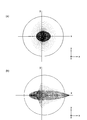
- A is a spot diagram of an optical system in which the x-direction shift is corrected.
- (B) is a spot diagram of an optical system in which an x-direction shift occurs.
- the endoscope system according to the embodiment of the present invention it is a diagram showing an imaging state when an image is formed on an imaging device after an odd number of reflections by a beam splitter.
- SA spherical aberration
- AS astigmatism
- DT distortion
- CC lateral chromatic aberration
- E respectively show spherical aberration
- AS astigmatism
- DT distortion
- CC lateral chromatic aberration
- the endoscope system divides an object optical system OBL and a subject image obtained by the objective optical system OBL into two optical images with different focus using two prisms.
- An image combining process for generating a composite image by selecting an image having a relatively high contrast between the acquired two optical images in a predetermined region
- the two prisms are bonded so that the bonding surfaces are substantially parallel to each other with a bonding agent interposed between the bonding surface and the objective optical system OBL.
- the optical axis forms an angle of 45 degrees and satisfies the following conditional expression (1).
- the unit of angle is degrees.
- im_pitch is the pixel pitch of the image sensor 22
- ⁇ ′ is the refraction angle of the light ray incident on the bonding surface 21h
- d is the thickness of the bonding agent 21g, It is.
- FIG. 2 is a diagram illustrating a schematic configuration of the optical path splitting unit 20.
- the light emitted from the objective optical system OBL enters the optical path dividing unit 20.
- the optical path splitting unit 20 includes a polarizing beam splitter 21 that splits a subject image into two optical images with different focus, and an image sensor 22 that captures two optical images and acquires two images.
- the polarization beam splitter 21 includes a first prism 21b, a second prism 21e, a mirror 21c, and a ⁇ / 4 plate 21d. Both the first prism 21b (object-side prism) and the second prism 21e (image-side prism) have beam split surfaces having an inclination of 45 degrees with respect to the optical axis AX.
- a polarization splitting film 21f is formed on the beam splitting surface of the first prism 21b.
- the first prism 21b and the second prism 21e constitute the polarization beam splitter 21 by bringing the beam split surfaces into contact with each other via the polarization separation film 21f.
- the mirror 21c is provided near the end face of the first prism 21b via a ⁇ / 4 plate 21d.
- An image sensor 22 is attached to the end face of the second prism 21e via a cover glass CG.
- the subject image from the objective optical system OBL is separated into a P-polarized component (transmitted light) and an S-polarized component (reflected light) by the polarization separation film 21f provided on the beam splitting surface in the first prism 21b, and the reflected light side And an optical image on the transmitted light side are separated into two optical images.
- the optical image of the S-polarized component is reflected to the imaging element 22 by the polarization separation film 21f, passes through the A optical path, passes through the ⁇ / 4 plate 21d, is reflected by the mirror 21c, and is folded back to the imaging element 22 side. It is.
- the folded optical image is transmitted through the ⁇ / 4 plate 21d again to rotate the polarization direction by 90 °, passes through the polarization separation film 21f, and forms an image on the imaging device 22.
- the optical image of the P-polarized component passes through the polarization separation film 21f, passes through the B optical path, and is reflected by a mirror surface provided on the opposite side of the beam splitting surface of the second prism 21e that folds vertically toward the image sensor 22.
- the image is formed on the image sensor 22.
- a prism glass path is set so that a predetermined optical path difference of, for example, about several tens of ⁇ m is generated between the A optical path and the B optical path, and two optical images with different focus are received on the light receiving surface of the image sensor 22. To form an image.
- the first prism 21b and the second prism 21e can be separated into two optical images having different focus positions so that the optical path length (glass path length) on the transmitted light side to the imaging element 22 in the first prism 21b can be separated.
- the optical path length on the reflected light side is short (small).
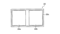
- the image sensor 22 receives two optical images with different focus positions and individually receives and captures two optical regions (effective pixels) in the entire pixel area of the image sensor 22. Regions) 22a and 22b are provided.
- the light receiving regions 22a and 22b are arranged so as to coincide with the image planes of these optical images in order to capture two optical images.
- the light receiving area 22a is relatively shifted (shifted) to the near point side with respect to the light receiving area 22b, and the light receiving area 22b is in focus with respect to the light receiving area 22a.
- the position is relatively shifted to the far point side. Thereby, two optical images with different focus are formed on the light receiving surface of the image sensor 22.
- the optical path length to the image sensor 22 is changed so that the focus position with respect to the light receiving regions 22a and 22b is relatively shifted. Also good.
- a correction pixel area 22c for correcting a geometric shift of the optical image divided into two is provided around the light receiving areas 22a and 22b.
- a correction pixel area 22c for correcting a geometric shift of the optical image divided into two is provided.
- manufacturing errors are suppressed, and correction by image processing is performed by an image correction processing unit 23b (FIG. 6) described later, thereby eliminating the geometrical deviation of the optical image described above. It has become.
- the second lens group G2 of the present embodiment described above is a focusing lens and can be selectively moved to two positions in the direction of the optical axis.
- the second lens group G2 is driven by an actuator (not shown) so as to move from one position to the other position and from the other position to one position between two positions.
- the second lens group G2 In the state where the second lens group G2 is set to the front side (object side) position, the second lens group G2 is set so as to focus on the subject in the observation area when performing far-field observation (normal observation). Further, in the state where the second lens group G2 is set to the rear side position, it is set to focus on the subject in the observation region when performing close-up observation (magnification observation).
- the polarization beam splitter 21 when used for the polarization separation, the brightness of the separated image is different unless the polarization state of the light to be separated is a circular polarization. Regular brightness differences are relatively easy to correct in image processing. However, if brightness differences occur locally and under viewing conditions, they cannot be corrected completely, resulting in uneven brightness in the composite image. May end up.
- the subject observed with the endoscope may have uneven brightness in the relatively peripheral part of the visual field of the composite image. It should be noted that the brightness unevenness with the polarization state broken is conspicuous when the subject has a relatively saturated brightness distribution.
- the endoscope In the peripheral part of the visual field, the endoscope often sees the blood vessel running and the mucous membrane structure of the subject image relatively close to each other, and there is a high possibility that the image will be very troublesome for the user. Therefore, for example, as shown in FIG. 2, it is preferable to arrange the ⁇ / 4 plate 21a closer to the object side than the polarization separation film 21f of the optical path splitting unit 20 so as to return the polarization state to the circularly polarized state. .
- a half mirror that splits the intensity of incident light can be used instead of the polarizing beam splitter as described above.
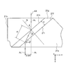
- FIG. 4 shows a configuration in the vicinity of the bonding agent 21 g of the optical path splitting unit 20.
- the first prism 21b and the second prism 21e are bonded so that the bonding surfaces 21h and 21i are substantially parallel to each other with a bonding agent 21g interposed therebetween.
- the bonding surface 21h and the optical axis AX of the objective optical system OBL form an angle of 45 degrees.
- the angle formed by the adhesive surface 21h and the optical axis AX of the objective optical system OBL may be approximately 45 degrees.
- the normal line of the bonding surface 21h is indicated by N.
- the light beam AL is refracted in the direction of the angle ⁇ ′ on the bonding surface 21h.
- the light beam is refracted by the difference between the refractive index of the prism and the refractive index of the bonding agent.
- This refraction occurs on the surface including the 45 slope of the prism (x direction in FIG. 4), but does not occur in the vertical direction (y direction in FIG. 4).
- the distance between the light beam AL that has traveled without being refracted and the light beam AL 'that has traveled after being refracted is referred to as x-direction shift x-sht (see FIG. 4). Note that the x-direction shift occurs in both the optical paths A and B in the prism.
- Nd_Pr01 ⁇ sin ⁇ Nd_CE ⁇ sin ⁇ ′ (A) here, Nd_Pr01 is the refractive index at the d-line of the first prism 21b on the object side, Nd_CE is the refractive index of the bonding agent 21g at the d-line, ⁇ is the incident angle of the light beam AL incident on the bonding surface 21h, ⁇ ′ is the refraction angle of the light beam AL incident on the bonding surface 21h, It is.
- Conditional expression (1) relates to x-direction shift.
- FIG. 5A is a diagram showing a spot diagram of the optical system in which the x-direction shift is corrected in the present embodiment.
- FIG. 5B is a spot diagram of an optical system in which an x-direction shift occurs in the conventional configuration.
- the objective optical system OBL is an ideal lens without aberration, a circular object at the center of the screen becomes elliptical on the image plane. For this reason, the resolution is deteriorated, which is not preferable.
- Satisfying conditional expression (1) makes it possible to reduce the x-direction shift, so that good optical performance can be obtained.
- conditional expression (1) If the upper limit value of conditional expression (1) is exceeded or less than the lower limit value, the maximum value of the x-direction shift becomes larger than the pixel pitch of the image sensor. For this reason, since optical performance will deteriorate, it is not preferable.
- conditional expression (1) ′ instead of conditional expression (1).
- conditional expression (1) ′′ instead of conditional expression (1).
- Nd_Pr01 is the refractive index at the d-line of the first prism 21b on the object side
- Nd_Pr02 is a refractive index at the d-line of the second prism 21e on the image side
- Nd_CE is the refractive index of the bonding agent 21g at the d-line
- the refractive index Nd_Pr01 of the first prism 21b and the refractive index Nd_Pr02 of the second prism 21e are desirably the same value.
- Conditional expression (2) relates to an appropriate ratio between the refractive index of the first prism 21b and the refractive index of the bonding agent 21g. Satisfying the conditional expression (2) is preferable because the amount of refraction of the light beam AL at the interface between the first prism 21b and the bonding agent 21g becomes small.
- conditional expression (2) When the upper limit value of conditional expression (2) is exceeded or below the lower limit value, the amount of refraction of the light beam AL at the interface between the first prism 21b and the bonding agent 21g increases. This is not preferable because the x-direction shift becomes too large.
- Conditional expression (3) relates to an appropriate ratio of the refractive indexes of the second prism 21e and the bonding agent 21g. Satisfying the conditional expression (3) is preferable because the amount of refraction of the light beam AL at the interface between the second prism 21e and the bonding agent 21g becomes small.
- conditional expression (3) If the upper limit value of conditional expression (3) is exceeded or below the lower limit value, the amount of light refraction at the interface between the second prism 21e and the bonding agent 21g increases. This is not preferable because the x-direction shift becomes too large.
- conditional expressions (2) ′ and (3) ′ are preferably satisfied instead of conditional expressions (2) and (3).
- 0.8 ⁇ Nd_Pr01 / Nd_CE ⁇ 1.2 (2) ′ 0.8 ⁇ Nd_Pr02 / Nd_CE ⁇ 1.2 (3) ′
- 0.9 ⁇ Nd_Pr02 / Nd_CE ⁇ 1.11 (3) "
- d is the thickness of the bonding agent 21g
- ⁇ ′ is the refraction angle of the light ray incident on the bonding surface 21h
- fw is the focal length in the normal observation state of the objective optical system
- ih is the image height
- Conditional expression (4) relates to an appropriate ratio between the x-direction shift and the focal length of the objective optical system.
- conditional expression (4) If the upper limit value of conditional expression (4) is exceeded, the x-direction shift becomes too large and the resolution is deteriorated, which is not preferable.
- conditional expression (4) If the lower limit value of conditional expression (4) is not reached, the x-direction shift almost does not exist, so the problem of the present application itself does not occur.
- Conditional expression (5) relates to an appropriate ratio between x-direction shift and image height.
- conditional expression (5) If the upper limit value of conditional expression (5) is exceeded, the x-direction shift becomes too large, and the resolution is deteriorated.
- conditional expression (5) If the lower limit of conditional expression (5) is not reached, there is almost no x-direction shift, so the problem of the present application itself does not occur.
- conditional expressions (4) ′ and (5) ′ are preferably satisfied instead of conditional expressions (4) and (5).
- (4) ′ 0.0015 ⁇ d ⁇ sin ( ⁇ ′ ⁇ 45) / (cos ⁇ ′ ⁇ ih) ⁇ 0.5 (5) ′
- the first negative lens is provided on the most object side of the objective optical system and the following conditional expressions (6) and (7) are satisfied.
- Nd_L01 is a refractive index at the d-line of the negative first lens L1
- Nd_CE is the refractive index of the bonding agent 21g at the d-line
- Nd_Pr01 is the refractive index at the d-line of the object-side prism 21b, It is.
- Conditional expression (6) relates to an appropriate ratio between the refractive index of the negative first lens L1 and the refractive index of the bonding agent 21g.
- Conditional expression (7) relates to an appropriate ratio between the refractive index of the negative first lens L1 and the refractive index of the first prism 21b.
- conditional expression (7) If the upper limit of conditional expression (7) is exceeded, the refractive index of the first prism 21b becomes too small, making it difficult to obtain the material, which is not preferable.
- conditional expressions (6) ′ and (7) ′ instead of the conditional expressions (6) and (7).
- 0.8 ⁇ Nd_L01 / Nd_CE ⁇ 1.4 (6) ′ 0.8 ⁇ Nd_L01 / Nd_Pr01 ⁇ 1.3 (7) ′
- conditional expressions (6) "and (7)” instead of the conditional expressions (6) and (7). 0.95 ⁇ Nd_L01 / Nd_CE ⁇ 1.3 (6) " 0.95 ⁇ Nd_L01 / Nd_Pr01 ⁇ 1.2 (7) "
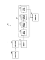
- the image processor 23 reads an image relating to two optical images captured by the image sensor 22 and has different focus positions, and an image for performing image correction on the two images read by the image reading unit 23a.
- the image processing apparatus includes a correction processing unit 23b and an image composition processing unit 23c that performs image composition processing for compositing two corrected images.
- the image correction processing unit 23b corrects the images related to the two optical images formed on the light receiving regions 22a and 22b of the image sensor 22 so that the differences other than the focus are substantially the same. That is, the two images are corrected so that the relative positions, angles, and magnifications in the optical images of the two images are substantially the same.
- each optical image formed on the light receiving regions 22a and 22b of the image sensor 22 may have a relative displacement, a displacement, an angle, that is, a displacement in the rotation direction, and the like.
- the lower one of the two images or images or the image or image having the lower luminance at the relatively same position of the two images or images is used as a reference. It is desirable to make corrections.
- the image composition processing unit 23c selects a relatively high contrast image in a corresponding region between the two images corrected by the image correction processing unit 23b, and generates a composite image. That is, by comparing the contrast in each spatially identical pixel area in two images and selecting a pixel area having a relatively higher contrast, a composite image as one image synthesized from the two images Is generated.
- a composite image is generated by a composite image process in which the pixel area is added with a predetermined weight.
- the image processor 23 performs subsequent image processing such as color matrix processing, contour enhancement, and gamma correction on one image synthesized by the image synthesis processing unit 23c.
- the image output unit 23d outputs an image that has been subjected to subsequent image processing.
- the image output from the image output unit 23d is output to the image display unit 24.
- first prism 21b and the second prism 21e are made of different glass materials according to the near point optical path and the far point optical path leading to the image sensor 22, and the refractive index is made different so that the relative focus position is relatively increased. It may be shifted.
- step S101 the image correction processing unit 23b performs a correction process on two images, that is, the image related to the far point image and the image related to the near point image acquired by the image sensor 22 in the image correction unit 22b. That is, according to a preset correction parameter, the two images are corrected so that the relative position, angle, and magnification in the optical images of the two images are substantially the same, and the corrected images are combined.
- the data is output to the processing unit 23c.
- step S102 the two images that have undergone the correction processing are combined by the image combining processing unit 23c. At this time, contrast values are calculated and compared in the corresponding pixel regions of the two perspective images.
- step S103 it is determined whether or not there is a difference in the compared contrast values. If there is a difference in contrast, the process proceeds to step S105, where a region having a high contrast value is selected and synthesized.
- the difference in the contrast value to be compared is small or almost the same, it becomes an unstable factor in processing which of the two perspective images is selected. For example, if there are fluctuations in a signal such as noise, a discontinuous region may be generated in the composite image, or a problem may occur that the originally resolved subject image is blurred.
- step S104 if the contrast values of the two images are substantially the same in the pixel region to be subjected to the contrast comparison, weighting is performed, and the image weighted in the next step S105 is added to perform image selection. The instability is resolved.
- the field of view is prevented while preventing a discontinuous region from being generated in the composite image or the optical image from being blurred due to noise or the like.
- An image with an increased depth can be acquired.
- the manufacturing cost is reduced and the depth of field is increased without increasing the size of the device as compared with a device including a plurality of imaging devices. Can be obtained.
- a desired depth of field can be obtained, and degradation of resolution can be prevented.
- the mirror image correction by the odd number of reflections may be reversed by the image correction processing unit 23b. It is preferable to carry out by.
- the imaging element 22 has a long shape in the endoscope longitudinal direction, it is preferable to appropriately rotate the composite image in consideration of the aspect ratio of the image display unit 24.
- FIGS. 9A and 9B are diagrams showing a cross-sectional configuration of the objective optical system.
- FIG. 9A is a diagram showing a cross-sectional configuration of the objective optical system in a normal observation state (a long distance object point).
- FIG. 2B is a diagram showing a cross-sectional configuration of the objective optical system in the close-up observation state (short-distance object point).
- the objective optical system includes, in order from the object side, a first lens group G1 having a negative refractive power, a second lens group G2 having a positive refractive power, and a third lens group G3 having a positive refractive power. , Is composed of.
- the aperture stop S is disposed between the second lens group G2 and the third lens group G3.
- the second lens group G2 moves on the optical axis AX to the image side, and corrects the change in the focal position accompanying the change from the normal observation state to the close observation state.
- the first lens group G1 includes, in order from the object side, a plano-concave negative lens L1 having a plane facing the object side, a parallel flat plate L2, a biconcave negative lens L3, and a plano-convex positive lens L4 having a plane facing the image side. And consist of Here, the negative lens L3 and the positive lens L4 are cemented.
- the second lens group G2 includes a positive meniscus lens L5 having a convex surface directed toward the object side.
- the third lens group G3 includes, in order from the object side, a biconvex positive lens L6, a negative meniscus lens L7 with a convex surface facing the image side, a planoconvex positive lens L8 with a plane facing the object side, and a biconvex positive lens.
- L9 and a negative meniscus lens L10 having a convex surface facing the image side.
- the positive lens L6 and the negative meniscus lens L7 are cemented.
- the positive lens L9 and the negative meniscus lens L10 are cemented.
- the optical path splitting unit 20 described above is disposed on the image side of the third lens group G3. In the prism in the optical system, the optical path is bent.
- the parallel flat plate L2 is a filter provided with a coating for cutting a specific wavelength, for example, 1060 nm of a YAG laser, 810 nm of a semiconductor laser, or an infrared region.
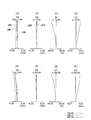
- FIGS. 10A, 10B, 10C, and 10D show spherical aberration (SA), astigmatism (AS), distortion aberration (DT), and lateral chromatic aberration (CC) in the normal observation state of this embodiment.
- 10E, 10F, 10G, and 10H show spherical aberration (SA), astigmatism (AS), distortion aberration (DT), and lateral chromatic aberration (CC) in the close-up observation state of this example. ).
- These aberration diagrams are shown for wavelengths of 656.27 nm (C line), 587.56 nm (d line), and 435.84 nm (g line). In each figure, “ ⁇ ” indicates a half angle of view.
- r are the radius of curvature of each lens surface
- d is the distance between the lens surfaces
- nd is the refractive index of the d-line of each lens
- ⁇ d is the Abbe number of each lens
- FNO is the F number
- ⁇ is the half field angle It is.
- the back focus fb represents the distance from the most image-side optical surface to the paraxial image surface in terms of air. The total length is obtained by adding back focus to the distance (not converted to air) from the lens surface closest to the object side to the optical surface closest to the image side.
- Example 1 The numerical values of conditional expressions (1) to (7) in Example 1, Example 2, and Example 3 are shown below.
- the specification values of the objective optical system OBL (Numerical Example 1) are common to the three examples.
- Conditional expression (1) d ⁇ sin ( ⁇ '-45) / (cos ⁇ ' ⁇ im_pitch) (2) Nd_Pr01 / Nd_CE (3) Nd_Pr02 / Nd_CE (4) d ⁇ sin ( ⁇ '-45) / (cos ⁇ ' ⁇ fw) (5) d ⁇ sin ( ⁇ '-45) / (cos ⁇ ' ⁇ ih) (6) Nd_L01 / Nd_CE (7) Nd_L01 / Nd_Pr01 Value corresponding to conditional expression Example 1 Example 2
- Example 3 (1) 1.12 1.92 9.98 (2) 1.10 1.14 1.29 (3) 1.10 1.14 1.29 (4) 0.0017 0.0038 0.013 (5) 0.0017 0.004 0.0135 (6) 1.26 1.26 1.29
- Example 1 Example 2
- Example 3 Nd_Pr01 1.63854 1.69895 1.883
- Nd_Pr02 1.63854 1.69895 1.883
- Nd_CE 1.49 1.49 1.46 d 0.01 0.015 0.015 ⁇ '51.04 53.73 65.78 im_pitch (um) 1.5 2
- im_pitch (um) 1.5 2
- 1.3 fw 1 1 1 ih 0.959 0.959 0.959 Nd_L01 1.883 1.883 1.883
- the present invention is useful for an endoscope system that can acquire a high-quality image in which the depth of field is enlarged and aberrations are corrected favorably.
Landscapes
- Health & Medical Sciences (AREA)
- Life Sciences & Earth Sciences (AREA)
- Engineering & Computer Science (AREA)
- Physics & Mathematics (AREA)
- Surgery (AREA)
- Optics & Photonics (AREA)
- Medical Informatics (AREA)
- General Health & Medical Sciences (AREA)
- Biophysics (AREA)
- Pathology (AREA)
- Radiology & Medical Imaging (AREA)
- Veterinary Medicine (AREA)
- Biomedical Technology (AREA)
- Heart & Thoracic Surgery (AREA)
- Public Health (AREA)
- Molecular Biology (AREA)
- Animal Behavior & Ethology (AREA)
- Nuclear Medicine, Radiotherapy & Molecular Imaging (AREA)
- Multimedia (AREA)
- Signal Processing (AREA)
- General Physics & Mathematics (AREA)
- Computing Systems (AREA)
- Theoretical Computer Science (AREA)
- Astronomy & Astrophysics (AREA)
- Instruments For Viewing The Inside Of Hollow Bodies (AREA)
- Lenses (AREA)
- Endoscopes (AREA)
- Optical Elements Other Than Lenses (AREA)
- Studio Devices (AREA)
Abstract
画面の中心領域から周辺領域にかけて良好な画質を得ることができる内視鏡システムを提供すること。 対物光学系OBLと、対物光学系OBLで得られた被写体像を2つのピントの異なる光学像に2つのプリズムを用いて分割する光路分割部20と、2つの光学像を取得する1つの撮像素子22と、取得した2つの光学像を相対的にコントラストが高い画像を所定領域において選択し、合成画像を生成する画像合成処理部23と、を有する内視鏡システムであって、2つのプリズムは、接合剤を介在して接着面どうしが略並行になるように接着され、接着面と対物光学系OBLの光軸は、45度の角度をなすとともに、以下の条件式(1)を満足することを特徴とする。 -10<d×sin(θ'-45)/(cosθ'×im_pitch)<10 …(1)
Description
本発明は、内視鏡システム、特に被写界深度内視鏡システムに関する。
一般に、内視鏡システムを始め、撮像素子を備えた機器において、撮像素子の高画素化に伴い、被写界深度が狭くなることが知られている。すなわち、撮像素子において、画素数を増やすために画素ピッチ(1画素の縦横の寸法)を小さくすると、これに伴って許容錯乱円も小さくなるため、撮像装置の被写界深度が狭くなる。
被写界深度を拡大するために、例えば、特許文献1、2、3には、自画像を分割して結像させ、取得した画像を画像処理で合成し深度を拡大する構成が開示されている。この構成では、自画像を分割して結像させ、取得した画像を画像処理で合成し深度を拡大するという点で優れている。
しかしながら、特許文献1、2、3の構成では撮像素子が複数必要となり、コストが上昇するため好ましくない。
本発明は、上記に鑑みてなされたものであって、プリズムを用いた自画像分割における深度拡大技術を用いた内視鏡システムにおいて、画面の中心領域から周辺領域にかけて良好な画質を得ることができる内視鏡システムを提供することを目的とする。
上述した課題を解決し、目的を達成するために、本発明は、以下の手段を提供する。
本発明に係る内視鏡システムの一態様は、
対物光学系と、
対物光学系で得られた被写体像を2つのピントの異なる光学像に2つのプリズムを用いて分割する光路分割部と、
2つの光学像を取得する1つの撮像素子と、
取得した2つの光学像を相対的にコントラストが高い画像を所定領域において選択し、合成画像を生成する画像合成処理部と、を有する内視鏡システムであって、
2つのプリズムは、接合剤を介在して接着面どうしが略並行になるように接着され、
接着面と対物光学系の光軸は、45度の角度をなすとともに、以下の条件式(1)を満足することを特徴とする。角度の単位は、度である
-10<d×sin(θ’-45)/(cosθ’×im_pitch)<10 …(1)
ここで、
im_pitchは、撮像素子の画素ピッチ、
θ’は、接着面へ入射した光線の屈折角、
dは、接合剤の厚さ、
である。
本発明に係る内視鏡システムの一態様は、
対物光学系と、
対物光学系で得られた被写体像を2つのピントの異なる光学像に2つのプリズムを用いて分割する光路分割部と、
2つの光学像を取得する1つの撮像素子と、
取得した2つの光学像を相対的にコントラストが高い画像を所定領域において選択し、合成画像を生成する画像合成処理部と、を有する内視鏡システムであって、
2つのプリズムは、接合剤を介在して接着面どうしが略並行になるように接着され、
接着面と対物光学系の光軸は、45度の角度をなすとともに、以下の条件式(1)を満足することを特徴とする。角度の単位は、度である
-10<d×sin(θ’-45)/(cosθ’×im_pitch)<10 …(1)
ここで、
im_pitchは、撮像素子の画素ピッチ、
θ’は、接着面へ入射した光線の屈折角、
dは、接合剤の厚さ、
である。
本発明は、プリズムを用いた自画像分割における深度拡大技術を用いた内視鏡システムにおいて、画面の中心領域から周辺領域にかけて良好な画質を得ることができる内視鏡システムを提供できるという効果を奏する。
以下、本実施形態に係る内視鏡システムについて、図面を用いて、このような構成をとった理由と作用を説明する。なお、以下の実施形態によりこの発明が限定されるものではない。
本実施形態に係る内視鏡システムは、図1に示すように、対物光学系OBLと、対物光学系OBLで得られた被写体像を2つのピントの異なる光学像に2つのプリズムを用いて分割する光路分割部20と、2つの光学像を取得する1つの撮像素子22と、取得した2つの光学像を相対的にコントラストが高い画像を所定領域において選択し、合成画像を生成する画像合成処理部23(図6)と、を有する内視鏡システムであって、2つのプリズムは、接合剤を介在して接着面どうしが略並行になるように接着され、接着面と対物光学系OBLの光軸は、45度の角度をなすとともに、以下の条件式(1)を満足することを特徴とする。角度の単位は、度である。
-10<d×sin(θ’-45)/(cosθ’×im_pitch)<10 …(1)
ここで、
im_pitchは、撮像素子22の画素ピッチ、
θ’は、接着面21hへ入射した光線の屈折角、
dは、接合剤21gの厚さ、
である。
-10<d×sin(θ’-45)/(cosθ’×im_pitch)<10 …(1)
ここで、
im_pitchは、撮像素子22の画素ピッチ、
θ’は、接着面21hへ入射した光線の屈折角、
dは、接合剤21gの厚さ、
である。
光路分割部20の構成を説明する。図2は、光路分割部20の概略構成を示す図である。
対物光学系OBLを射出した光は、光路分割部20に入射する。
光路分割部20は、被写体像をピントの異なる2つの光学像に分割する偏光ビームスプリッタ21、2つの光学像を撮像して2つの画像を取得する撮像素子22を有する。
偏光ビームスプリッタ21は、図2に示すように、第1プリズム21b、第2プリズム21e、ミラー21c、及びλ/4板21dを備えている。第1プリズム21b(物体側のプリズム)及び第2プリズム21e(像側のプリズム)は共に光軸AXに対して45度の斜度であるビームスプリット面を有する。
第1プリズム21bのビームスプリット面には偏光分離膜21fが形成されている。そして、第1プリズム21b及び第2プリズム21eは、互いのビームスプリット面を偏光分離膜21fを介して当接させて偏光ビームスプリッタ21を構成している。
また、ミラー21cは、第1プリズム21bの端面近傍にλ/4板21dを介して設けられている。第2プリズム21eの端面には、カバーガラスCGを介して撮像素子22が取り付けられている。
対物光学系OBLからの被写体像は、第1プリズム21bにおいてビームスプリット面に設けられた偏光分離膜21fによりP偏光成分(透過光)とS偏光成分(反射光)とに分離され、反射光側の光学像と透過光側の光学像との2つの光学像に分離される。
S偏光成分の光学像は、偏光分離膜21fで撮像素子22に対して対面側に反射されA光路を通り、λ/4板21dを透過後、ミラー21cで反射され、撮像素子22側に折り返される。折り返された光学像は、λ/4板21dを再び透過する事で偏光方向が90°回転し、偏光分離膜21fを透過して撮像素子22に結像される。
P偏光成分の光学像は、偏光分離膜21fを透過してB光路を通り、撮像素子22に向かって垂直に折り返す第2プリズム21eのビームスプリット面と反対側に設けられたミラー面によって反射され、撮像素子22に結像される。この際、A光路とB光路で、例えば、数十μm程度の所定の光路差を生じさせるように、プリズム硝路を設定しておき、ピントが異なる2つの光学像を撮像素子22の受光面に結像させる。
すなわち、第1プリズム21b及び第2プリズム21eを、被写体像をピント位置が異なる2つの光学像に分離できるように、第1プリズム21bにおける撮像素子22に至る透過光側の光路長(硝路長)に対して反射光側の光路長が短く(小さく)なるように配置する。
撮像素子22は、図3に示すように、ピント位置が異なる2つの光学像を各々個別に受光して撮像するために、撮像素子22の全画素領域の中に、2つの受光領域(有効画素領域)22a、22bが設けられている。
受光領域22a、22bは、2つの光学像を撮像するために、これらの光学像の結像面と各々一致するように配置されている。そして、撮像素子22において、受光領域22aは受光領域22bに対してそのピント位置が相対的に近点側にシフトしており(ずれており)、受光領域22bは受光領域22aに対してそのピント位置が相対的に遠点側にシフトしている。これにより、ピントが異なる2つの光学像を撮像素子22の受光面に結像させるように構成されている。
なお、第1プリズム21bと第2プリズム21eにおける両者の硝材の屈折率を異ならせることにより、撮像素子22に至る光路長を変えて受光領域22a、22bに対するピント位置を相対的にずらすようにしても良い。
また、受光領域22a、22bの周囲には、2つに分割された光学像の幾何的なズレを補正するための補正画素領域22cが設けられている。補正画素領域22c内において製造上の誤差を抑え、後述する画像補正処理部23b(図6)にて画像処理による補正を行なうことで、上記した光学像の幾何学的なズレを解消するようになっている。
上述の本実施形態の第2レンズ群G2は、フォーカシングレンズであり、光軸の方向における2つの位置に選択的に移動可能である。不図示のアクチュエータにより、第2レンズ群G2は、2つの位置間で一方の位置から他方の位置、他方の位置から一方の位置に移動するように駆動される。
第2レンズ群G2を、前方側(物体側)の位置に設定した状態においては遠方観察(通常観察)する場合の観察領域の被写体にピントが合うように設定される。また、第2レンズ群G2を後方側の位置に設定した状態においては近接観察(拡大観察)する場合の観察領域の被写体にピントが合うように設定されている。
なお、本実施形態のように、偏光ビームスプリッタ21を適用して偏光分離をする場合、分離する光の偏光状態が円偏光でないと分離した像の明るさに差が生じてしまう。規則的な明るさの差異は画像処理での補正が比較的容易であるが、局所的に且つ観察条件で明るさの差異が生じた場合、補正しきれなくなり、合成画像に明るさムラが生じてしまう場合がある。
内視鏡で観察する被写体は、合成画像の比較的視野周辺部で明るさムラが生じてしまう可能性がある。なお、この偏光状態が崩れた明るさムラは、被写体が比較的飽和気味の明るさ分布であると顕著に生じる。
視野の周辺部において、内視鏡では比較的近接して被写体像の血管走行や粘膜構造を見る事が多く、ユーザーにとって非常に煩わしい画像になる可能性が高い。
そこで、例えば、図2に示すように、この偏光状態が崩れた状態を円偏光に戻す様にλ/4板21aを、光路分割部20の偏光分離膜21fより物体側に配置することが好ましい。
そこで、例えば、図2に示すように、この偏光状態が崩れた状態を円偏光に戻す様にλ/4板21aを、光路分割部20の偏光分離膜21fより物体側に配置することが好ましい。
なお、上述のような偏光ビームスプリッタの代わりに、入射光を強度分割するハーフミラーを用いることもできる。
本実施形態における光路分割部20について、さらに説明する。図4は、光路分割部20の接合剤21g近傍の構成を示している。第1プリズム21bと、第2プリズム21eは、接合剤21gを介在して接着面21h、21iどうしが略並行になるように接着されている。接着面21hと対物光学系OBLの光軸AXは、45度の角度をなしている。なお、接着面21hと対物光学系OBLの光軸AXのなす角度は、略45度であれば良い。
光軸AXに沿って進行する光線ALは、第1プリズム21bの接着面21hに対して入射角θ=45°で入射する。接着面21hの法線をNで示す。そして、光線ALは、接着面21hにおいて角度θ’の方向に屈折する。
2つの45度プリズムを用いて光路を分割する光学系では、プリズムの屈折率と接合剤の屈折率との差によって光線が屈折する。この屈折は、プリズムの45斜面度を含む面(図4のx方向)には発生するが、その垂直方向(図4のy方向)では発生しない。屈折しないで進行した光線ALと、屈折して進行した光線AL’との距離をx方向シフトx-shtとする(図4参照)。なお、x方向シフトは、プリズムにおけるA光路とB光路との両方の光路において発生する。
図4の構成において、以下の式(A)の屈折の法則が成立する。
Nd_Pr01×sinθ=Nd_CE×sinθ’ (A)
ここで、
Nd_Pr01は、物体側の第1プリズム21bのd線における屈折率、
Nd_CEは、接合剤21gのd線における屈折率、
θは、接着面21hへ入射した光線ALの入射角、
θ’は、接着面21hへ入射した光線ALの屈折角、
である。
Nd_Pr01×sinθ=Nd_CE×sinθ’ (A)
ここで、
Nd_Pr01は、物体側の第1プリズム21bのd線における屈折率、
Nd_CEは、接合剤21gのd線における屈折率、
θは、接着面21hへ入射した光線ALの入射角、
θ’は、接着面21hへ入射した光線ALの屈折角、
である。
また、接合剤21gの厚さをdとすると、以下の式(B)が成立する。
α=d/cosθ’ (B)
α=d/cosθ’ (B)
式(A)、(B)からx方向シフトx-shtは、次式で示される。
x-sht=α×sin(θ’-θ)
=d×sin(θ’-θ)/cosθ’
このため、θ=45(°)として、x方向シフトx-shtをim_pitchで割ることで条件式(1)を得ることができる。
x-sht=α×sin(θ’-θ)
=d×sin(θ’-θ)/cosθ’
このため、θ=45(°)として、x方向シフトx-shtをim_pitchで割ることで条件式(1)を得ることができる。
条件式(1)は、x方向シフトに関する。図5(a)は、本実施形態において、x方向シフトが補正された光学系のスポットダイアグラムを示す図である。図5(b)は、従来構成において、x方向シフトが発生している光学系のスポットダイアグラムの図である。このように、光線ALのx方向シフトのため、対物光学系OBLを無収差の理想レンズにしても、画面中心において円形の物体が、像面では楕円形になってしまう。このため、解像力が劣化してしまうため好ましくない。
条件式(1)を満足することで、x方向シフトを小さくできるため、良好な光学性能を得ることができる。
条件式(1)の上限値を上回ると、または下限値を下回るとx方向シフトの最大値が、撮像素子の画素ピッチに対して大きくなってしまう。このため、光学性能が劣化してしまうため好ましくない。
なお、条件式(1)に代えて、以下の条件式(1)’を満たすことが望ましい。
-5<d×sin(θ’-45)/(cosθ’×im_pitch)<5 …(1)’
さらに、条件式(1)に代えて、以下の条件式(1)”を満たすことが望ましい。
-2<d×sin(θ’-45)/(cosθ’×im_pitch)<2 …(1)”
-5<d×sin(θ’-45)/(cosθ’×im_pitch)<5 …(1)’
さらに、条件式(1)に代えて、以下の条件式(1)”を満たすことが望ましい。
-2<d×sin(θ’-45)/(cosθ’×im_pitch)<2 …(1)”
また、本実施形態の好ましい態様によれば、以下の条件式(2)、(3)を満足することが望ましい。
0.7<Nd_Pr01/Nd_CE<1.3 …(2)
0.7<Nd_Pr02/Nd_CE<1.3 …(3)
ここで、
Nd_Pr01は、物体側の第1プリズム21bのd線における屈折率、
Nd_Pr02は、像側の第2プリズム21eのd線における屈折率、
Nd_CEは、接合剤21gのd線における屈折率、
である。
なお、第1プリズム21bの屈折率Nd_Pr01と、第2プリズム21eの屈折率Nd_Pr02は、同じ値であることが望ましい。
0.7<Nd_Pr01/Nd_CE<1.3 …(2)
0.7<Nd_Pr02/Nd_CE<1.3 …(3)
ここで、
Nd_Pr01は、物体側の第1プリズム21bのd線における屈折率、
Nd_Pr02は、像側の第2プリズム21eのd線における屈折率、
Nd_CEは、接合剤21gのd線における屈折率、
である。
なお、第1プリズム21bの屈折率Nd_Pr01と、第2プリズム21eの屈折率Nd_Pr02は、同じ値であることが望ましい。
条件式(2)は、第1プリズム21bの屈折率と接合剤21gの屈折率の適切な比に関する。条件式(2)を満足することで、第1プリズム21bと接合剤21gの界面における光線ALの屈折量が小さくなるため好ましい。
条件式(2)の上限値を上回ると、または下限値を下回ると、第1プリズム21bと接合剤21gの界面における光線ALの屈折量が大きくなる。このため、x方向シフトが大きくなりすぎてしまうため好ましくない。
条件式(3)は、第2プリズム21eと接合剤21gの屈折率の適切な比に関する。条件式(3)を満足することで、第2プリズム21eと接合剤21gの界面における光線ALの屈折量が小さくなるため好ましい。
条件式(3)の上限値を上回ると、または下限値を下回ると、第2プリズム21eと接合剤21gの界面における光線の屈折量が大きくなる。このため、x方向シフトが大きくなりすぎてしまうため好ましくない。
なお、条件式(2)、(3)に代えて、以下の条件式(2)’、(3)’を満たすことが望ましい。
0.8<Nd_Pr01/Nd_CE<1.2 …(2)'
0.8<Nd_Pr02/Nd_CE<1.2 …(3)'
さらに、条件式(2)、(3)に代えて、以下の条件式(2)”、(3)”を満たすことが望ましい。
0.9<Nd_Pr01/Nd_CE<1.11 …(2)”
0.9<Nd_Pr02/Nd_CE<1.11 …(3)”
0.8<Nd_Pr01/Nd_CE<1.2 …(2)'
0.8<Nd_Pr02/Nd_CE<1.2 …(3)'
さらに、条件式(2)、(3)に代えて、以下の条件式(2)”、(3)”を満たすことが望ましい。
0.9<Nd_Pr01/Nd_CE<1.11 …(2)”
0.9<Nd_Pr02/Nd_CE<1.11 …(3)”
また、本実施形態の好ましい態様によれば、以下の条件式(4)、(5)を満足することが望ましい。
0.001<d×sin(θ’-45)/(cosθ’×fw)<5 …(4)
0.001<d×sin(θ’-45)/(cosθ’×ih)<3 …(5)
ここで、
dは、接合剤21gの厚さ、
θ’は、接着面21hへ入射した光線の屈折角、
fwは、対物光学系の通常観察状態における焦点距離、
ihは、像高、
である。
0.001<d×sin(θ’-45)/(cosθ’×fw)<5 …(4)
0.001<d×sin(θ’-45)/(cosθ’×ih)<3 …(5)
ここで、
dは、接合剤21gの厚さ、
θ’は、接着面21hへ入射した光線の屈折角、
fwは、対物光学系の通常観察状態における焦点距離、
ihは、像高、
である。
条件式(4)は、x方向シフトと対物光学系の焦点距離の適切な比に関する。条件式(4)を満足することで、適切なx方向シフトに抑えることができるため、解像力が大きく劣化することはない。
条件式(4)の上限値を上回ると、x方向シフトが大きくなりすぎてしまい、解像力が劣化してしまうため好ましくない。
条件式(4)の下限値を下回ると、x方向シフトはほぼ存在しなくなるため、本願の課題自体も生じない。
条件式(5)は、x方向シフトと像高の適切な比に関する。条件式(5)を満足することで、適切なx方向シフトを達成できるため、解像力が大きく劣化することはない。
条件式(5)の上限値を上回ると、x方向シフトが大きくなりすぎてしまい、解像力が劣化してしまうため好ましくない。
条件式(5)の下限値を下回ると、x方向シフトはほぼ存在しなくなるため、本願の課題自体も生じない。
なお、条件式(4)、(5)に代えて、以下の条件式(4)’、(5)’を満たすことが望ましい。
0.0015<d×sin(θ’-45)/(cosθ’×fw)<1 …(4)'
0.0015<d×sin(θ’-45)/(cosθ’×ih)<0.5 …(5)'
さらに、条件式(4)、(5)に代えて、以下の条件式(4)”、(5)”を満たすことが望ましい。
0.0016<d×sin(θ’-45)/(cosθ’×fw)<0.1 …(4)”
0.0016<d×sin(θ’-45)/(cosθ’×ih)<0.1 …(5)”
0.0015<d×sin(θ’-45)/(cosθ’×fw)<1 …(4)'
0.0015<d×sin(θ’-45)/(cosθ’×ih)<0.5 …(5)'
さらに、条件式(4)、(5)に代えて、以下の条件式(4)”、(5)”を満たすことが望ましい。
0.0016<d×sin(θ’-45)/(cosθ’×fw)<0.1 …(4)”
0.0016<d×sin(θ’-45)/(cosθ’×ih)<0.1 …(5)”
また、本実施形態の好ましい態様では、対物光学系の最も物体側に負の第1レンズを有し、以下の条件式(6)、(7)を満足することが望ましい。
0.7<Nd_L01/Nd_CE<1.5 …(6)
0.7<Nd_L01/Nd_Pr01<1.5 …(7)
ここで、
Nd_L01は、負の第1レンズL1のd線における屈折率、
Nd_CEは、接合剤21gのd線における屈折率、
Nd_Pr01は、物体側のプリズム21bのd線における屈折率、
である。
0.7<Nd_L01/Nd_CE<1.5 …(6)
0.7<Nd_L01/Nd_Pr01<1.5 …(7)
ここで、
Nd_L01は、負の第1レンズL1のd線における屈折率、
Nd_CEは、接合剤21gのd線における屈折率、
Nd_Pr01は、物体側のプリズム21bのd線における屈折率、
である。
条件式(6)は、負の第1レンズL1の屈折率と接合剤21gの屈折率の適切な比に関する。
条件式(6)の上限値を上回ると、接合剤21gの屈折率が小さくなりすぎてしまい、材料の入手性が困難になるため好ましくない。
条件式(6)の下限値を下回ると、負の第1レンズL1の屈折率が小さすぎてしまい十分な負のパワーを得られないため好ましくない。
条件式(7)は、負の第1レンズL1の屈折率と第1プリズム21bの屈折率との適切な比に関する。
条件式(7)の上限値を上回ると、第1プリズム21bの屈折率が小さくなりすぎてしまい、材料の入手性が困難になるため好ましくない。
条件式(7)の下限値を下回ると、負の第1レンズL1の屈折率が小さすぎてしまい十分な負のパワーを得られないため好ましくない。
なお、条件式(6)、(7)に代えて、以下の条件式(6)’、(7)’を満たすことが望ましい。
0.8<Nd_L01/Nd_CE<1.4 …(6)'
0.8<Nd_L01/Nd_Pr01<1.3 …(7)'
さらに、条件式(6)、(7)に代えて、以下の条件式(6)”、(7)”を満たすことが望ましい。
0.95<Nd_L01/Nd_CE<1.3 …(6)”
0.95<Nd_L01/Nd_Pr01<1.2 …(7)”
0.8<Nd_L01/Nd_CE<1.4 …(6)'
0.8<Nd_L01/Nd_Pr01<1.3 …(7)'
さらに、条件式(6)、(7)に代えて、以下の条件式(6)”、(7)”を満たすことが望ましい。
0.95<Nd_L01/Nd_CE<1.3 …(6)”
0.95<Nd_L01/Nd_Pr01<1.2 …(7)”
次に、図6を参照して、取得した2つの画像の合成に関して説明する。
画像プロセッサ23は、撮像素子22により撮像されたピント位置が異なる2つの光学像に係る画像を各々読み出す画像読出部23aと、画像読出部23aにより読み出された2つの画像に対する画像補正を行う画像補正処理部23bと、補正された2つの画像を合成する画像合成処理を行う画像合成処理部23cと、を有する。
画像補正処理部23bは、撮像素子22の受光領域22a、22bにそれぞれ結像される2つの光学像に係る画像に対し、互いのピント以外の差異が略同一となるように補正する。すなわち、2つの画像の各光学像における相対的な位置、角度及び倍率が略同一となるように2つの画像に対して補正を行う。
被写体像を2つに分離して撮像素子22に各々結像させる場合、幾何的な差異が生じる場合がある。すなわち、撮像素子22の受光領域22a、22bにそれぞれ結像される各々の光学像は、相対的に倍率ズレ、位置ズレ、角度すなわち回転方向のズレ等が発生する場合がある。
これらの差異を製造時などにおいて、完全に解消することは困難であるが、それらのズレ量が大きくなると、合成画像が2重画像となったり、不自然な明るさムラ等を生じたりする。このため、画像補正処理部23bにて上述した幾何的な差異、明るさ差異を補正する。
2つの画像間における明るさの差異を補正する場合、2つの像または画像のうち輝度の低い方の像または画像、もしくは2つの像または画像の相対的に同一位置における輝度の低い方を基準にして補正を行うことが望ましい。
画像合成処理部23cは、画像補正処理部23bにより補正された2つの画像間の対応する所定領域において、相対的にコントラストが高い画像を選択して合成画像を生成する。つまり、2つの画像における空間的に同一の画素領域それぞれにおけるコントラストを比較し、相対的にコントラストが高い方の画素領域を選択することにより、2つの画像から合成された1つの画像としての合成画像を生成する。
なお、2つの画像の同一の画素領域におけるコントラスト差が小さい又は略同一である場合は、その画素領域に所定の重み付けして加算する合成画像処理により、合成画像を生成する。
また、画像プロセッサ23は、画像合成処理部23cにより合成された1つの画像に対して、色マトリクス処理、輪郭強調、ガンマ補正等の後段画像処理を行う。画像出力部23dは、後段画像処理された画像を出力する。画像出力部23dから出力される画像は画像表示部24に出力される。
また、撮像素子22に至る近点光路と遠点光路とに応じて、第1プリズム21bと第2プリズム21eとを異なる硝材で構成し、屈折率を異ならせることにより、相対的にピント位置をずらしても良い。
これにより、ピントの異なる2つの光学像に係る画像を取得し、これら画像を画像合成処理部23cで合成して合成被写界深度を得ることができる。内視鏡検査で広い範囲を俯瞰してスクリーニングする際には遠方観察が適しており、病変の詳細を観察したり、診断したりする際には、近接観察が適している。
このような構成をとることで、より多画素化した撮像素子を使用しても解像力を落とすことなく被写界深度を拡大することが可能となる。更にフォーカシング機構があるので自在に観察範囲を切り替えて高画質の内視鏡観察や診断を行うことができる。
次に、本実施形態において、2つの光学像を合成する場合の流れを図7のフローチャートに従って説明する。
ステップS101において、撮像素子22において取得された、ピントの異なる遠点像に係る画像と近点像に係る画像とが、画像補正処理部23bにおいて、遠近2画像の補正処理が行なわれる。すなわち、予め設定された補正パラメータに従って、2つの画像の各光学像における相対的な位置、角度及び倍率が略同一となるように2つの画像に対して補正を行い、補正後の画像を画像合成処理部23cに出力する。なお、必要に応じて2画像の明るさや色の差異を補正してもよい。
ステップS102において、補正処理が行なわれた2つの画像が画像合成処理部23cにて合成される。この際、遠近2画像の各々対応する画素領域において、コントラスト値が各々算出され、比較される。
ステップS103において、比較されたコントラスト値に差があるか否かを判断し、コントラストに差がある場合、ステップS105に進み、コントラスト値の高い領域を選択して合成される。
ここで、比較するコントラスト値の差が小さい乃至はほぼ同じである場合には、遠近2画像のどちらを選択するか処理上の不安定要因となる。例えば、ノイズ等の信号の揺らぎがあると、合成画像に不連続領域が生じたり、本来は解像している被写体像がボケてしまうといった不具合を生じさせたりする。
そこで、ステップS104に進み、重み付けを行う。ステップS104において、コントラス比較を行なう画素領域において、2画像でコントラスト値がほぼ同一である場合には、重み付けを行い、次のステップS105で重み付けを行った画像の加算処理を行う事で、画像選択の不安定さを解消している。
このように、本実施形態によれば、近接観察及び遠方観察の何れにおいても、ノイズ等によって合成画像において不連続領域が発生したり、光学像がぼけたりすることを防止しながら、被写界深度を拡大させた画像を取得することができる。
また、2つの画像は、同一の撮像素子により撮像されているので、撮像素子を複数備えるものに比べて、製造コストを低減し、装置を大型化することなく被写界深度を拡大させた画像を取得することができる。
また、所望する被写界深度を得られ、解像力の劣化を防止できる。
なお、上述した図2の偏光ビームスプリッタ21の場合には、1回、つまり奇数回の反射後に撮像素子22に光学像が結像される。このため、何れか一方の画像が図8のような結像状態(鏡像)となり、画像プロセッサ23において鏡像を反転させて像方向を一致させる画像処理が施される。
光学的な偶数回の反射による鏡像の補正は、対物光学系の大型化やプリズムのコスト高となる場合があるので、奇数回の反射による鏡像の補正は、画像補正処理部23bにて鏡像反転により行なうことが好ましい。
なお、撮像素子22が、内視鏡長手方向に長尺な形状となっている場合には、画像表示部24のアスペクト比を考慮して合成画像を適宜回転させることが好ましい。
(実施例1)
次に、実施例1に係る内視鏡システムが有する対物光学系について説明する。
図9(a)、(b)は、対物光学系の断面構成を示す図である。ここで、図9(a)は、通常観察状態(遠距離物点)における対物光学系の断面構成を示す図である。図2(b)は、近接観察状態(近距離物点)における対物光学系の断面構成を示す図である。
次に、実施例1に係る内視鏡システムが有する対物光学系について説明する。
図9(a)、(b)は、対物光学系の断面構成を示す図である。ここで、図9(a)は、通常観察状態(遠距離物点)における対物光学系の断面構成を示す図である。図2(b)は、近接観察状態(近距離物点)における対物光学系の断面構成を示す図である。
本実施例に係る対物光学系は、物体側から順に、負の屈折力の第1レンズ群G1と、正の屈折力の第2レンズ群G2と、正の屈折力の第3レンズ群G3と、から構成されている。また、明るさ絞りSは、第2レンズ群G2と、第3レンズ群G3との間に配置されている。第2レンズ群G2は、光軸AX上を像側に移動して、通常観察状態から近接観察状態への変化に伴う焦点位置の変化を補正する。
第1レンズ群G1は、物体側から順に、物体側に平面を向けた平凹負レンズL1と、平行平板L2と、両凹負レンズL3と、像側に平面を向けた平凸正レンズL4と、からなる。ここで、負レンズL3と正レンズL4とは接合されている。第2レンズ群G2は、物体側に凸面を向けた正メニスカスレンズL5からなる。第3レンズ群G3は、物体側から順に、両凸正レンズL6と、像側に凸面を向けた負メニスカスレンズL7と、物体側に平面を向けた平凸正レンズL8と、両凸正レンズL9と、像側に凸面を向けた負メニスカスレンズL10と、からなる。ここで、正レンズL6と負メニスカスレンズL7とは接合されている。正レンズL9と負メニスカスレンズL10とは接合されている。
第3レンズ群G3の像側に、上述した光路分割部20を配置している。光学系中のプリズムでは、光路が折り曲げられる。なお、平行平板L2は、特定の波長、例えばYAGレーザーの1060nm、半導体レーザーの810nm、あるいは赤外域をカットするためのコーティングが施されたフィルターである。
図10(a)、(b)、(c)、(d)は、本実施例の通常観察状態における球面収差(SA)、非点収差(AS)、歪曲収差(DT)、倍率色収差(CC)を示す。
図10(e)、(f)、(g)、(h)は、本実施例の近接観察状態における球面収差(SA)、非点収差(AS)、歪曲収差(DT)、倍率色収差(CC)を示す。
これら、諸収差図は、656.27nm(C線)、587.56nm(d線)、及び435.84nm(g線)の各波長について示されている。また、各図中、「ω」は半画角を示す。
図10(e)、(f)、(g)、(h)は、本実施例の近接観察状態における球面収差(SA)、非点収差(AS)、歪曲収差(DT)、倍率色収差(CC)を示す。
これら、諸収差図は、656.27nm(C線)、587.56nm(d線)、及び435.84nm(g線)の各波長について示されている。また、各図中、「ω」は半画角を示す。
以下に、上記各実施例の数値データを示す。記号は、rは各レンズ面の曲率半径、dは各レンズ面間の間隔、ndは各レンズのd線の屈折率、νdは各レンズのアッベ数、FNOはFナンバー、ωは半画角である。また、バックフォーカスfbは、最も像側の光学面から近軸像面までの距離を空気換算して表したものである。全長は、最も物体側のレンズ面から最も像側の光学面までの距離(空気換算しない)にバックフォーカスを加えたものである。
数値実施例1
単位 mm
面データ
面番号 r d nd νd
1 ∞ 0.48 1.88300 40.76
2 1.647 1.49
3 ∞ 0.55 1.52100 65.12
4 ∞ 0.34
5 -7.955 0.96 1.88300 40.76
6 1.999 1.37 1.84666 23.78
7 ∞ 可変
8 1.962 0.85 1.48749 70.23
9 2.080 可変
10(絞り) ∞ 0.07
11 3.615 1.10 1.64769 33.79
12 -1.551 0.32 2.00330 28.27
13 -9.523 0.04
14 ∞ 0.78 1.69895 30.13
15 -2.831 0.04
16 11.007 0.92 1.48749 70.23
17 -2.335 0.34 1.92286 18.90
18 -5.022 4.48
像面 ∞
データ
通常観察状態 近接観察状態
焦点距離 1.00 1.00
有効FNO. 3.58 3.54
画角2ω 145.01 139.17
fb(in air) 4.44 4.35
全長(in air) 16.18 16.18
d7 0.45 1.17
d10 1.60 0.88
各群焦点距離
f1=-1.21 f2=21.02 f3=3.23
単位 mm
面データ
面番号 r d nd νd
1 ∞ 0.48 1.88300 40.76
2 1.647 1.49
3 ∞ 0.55 1.52100 65.12
4 ∞ 0.34
5 -7.955 0.96 1.88300 40.76
6 1.999 1.37 1.84666 23.78
7 ∞ 可変
8 1.962 0.85 1.48749 70.23
9 2.080 可変
10(絞り) ∞ 0.07
11 3.615 1.10 1.64769 33.79
12 -1.551 0.32 2.00330 28.27
13 -9.523 0.04
14 ∞ 0.78 1.69895 30.13
15 -2.831 0.04
16 11.007 0.92 1.48749 70.23
17 -2.335 0.34 1.92286 18.90
18 -5.022 4.48
像面 ∞
データ
通常観察状態 近接観察状態
焦点距離 1.00 1.00
有効FNO. 3.58 3.54
画角2ω 145.01 139.17
fb(in air) 4.44 4.35
全長(in air) 16.18 16.18
d7 0.45 1.17
d10 1.60 0.88
各群焦点距離
f1=-1.21 f2=21.02 f3=3.23
以下、実施例1、実施例2、実施例3における条件式(1)~(7)の数値を示す。なお、対物光学系OBL(数値実施例1)の諸元値は、3つの実施例に関して、共通している。
条件式
(1) d×sin(θ'-45)/(cosθ'×im_pitch)
(2) Nd_Pr01/Nd_CE
(3) Nd_Pr02/Nd_CE
(4) d×sin(θ'-45)/(cosθ'×fw)
(5) d×sin(θ'-45)/(cosθ'×ih)
(6) Nd_L01/Nd_CE
(7) Nd_L01/Nd_Pr01
条件式対応値
実施例1 実施例2 実施例3
(1) 1.12 1.92 9.98
(2) 1.10 1.14 1.29
(3) 1.10 1.14 1.29
(4) 0.0017 0.0038 0.013
(5) 0.0017 0.004 0.0135
(6) 1.26 1.26 1.29
(7) 1.15 1.11 1.00
パラメータ値
屈折率は、d線における屈折率である。
実施例1 実施例2 実施例3
Nd_Pr01 1.63854 1.69895 1.883
Nd_Pr02 1.63854 1.69895 1.883
Nd_CE 1.49 1.49 1.46
d 0.01 0.015 0.015
θ' 51.04 53.73 65.78
im_pitch(um) 1.5 2 1.3
fw 1 1 1
ih 0.959 0.959 0.959
Nd_L01 1.883 1.883 1.883
条件式
(1) d×sin(θ'-45)/(cosθ'×im_pitch)
(2) Nd_Pr01/Nd_CE
(3) Nd_Pr02/Nd_CE
(4) d×sin(θ'-45)/(cosθ'×fw)
(5) d×sin(θ'-45)/(cosθ'×ih)
(6) Nd_L01/Nd_CE
(7) Nd_L01/Nd_Pr01
条件式対応値
実施例1 実施例2 実施例3
(1) 1.12 1.92 9.98
(2) 1.10 1.14 1.29
(3) 1.10 1.14 1.29
(4) 0.0017 0.0038 0.013
(5) 0.0017 0.004 0.0135
(6) 1.26 1.26 1.29
(7) 1.15 1.11 1.00
パラメータ値
屈折率は、d線における屈折率である。
実施例1 実施例2 実施例3
Nd_Pr01 1.63854 1.69895 1.883
Nd_Pr02 1.63854 1.69895 1.883
Nd_CE 1.49 1.49 1.46
d 0.01 0.015 0.015
θ' 51.04 53.73 65.78
im_pitch(um) 1.5 2 1.3
fw 1 1 1
ih 0.959 0.959 0.959
Nd_L01 1.883 1.883 1.883
以上、本発明の種々の実施形態について説明したが、本発明は、これらの実施形態のみに限られるものではなく、その趣旨を逸脱しない範囲で、これら実施形態の構成を適宜組合せて構成した実施形態も本発明の範疇となるものである。
以上のように、本発明は、被深度が拡大され、良好に収差が補正された高画質な画像を取得できる内視鏡システムに有用である。
10 内視鏡システム
20 光路分割部
21 偏光ビームスプリッタ
21a λ/4板
21b 第1プリズム
21c ミラー
21d λ/4板
21e 第2プリズム
21f 偏光分離膜
21g 接合剤
21h、21i 接着面
22 撮像素子
22a、22b 受光領域
22c 補正画素領域
23 画像プロセッサ
23a 画像読出部
23b 画像補正処理部
23c 画像合成処理部
23d 画像出力部
24 画像表示部
CG カバーガラス
OBL 対物光学系
G1 第1レンズ群
G2 第2レンズ群
G3 第3レンズ群
S 明るさ絞り
20 光路分割部
21 偏光ビームスプリッタ
21a λ/4板
21b 第1プリズム
21c ミラー
21d λ/4板
21e 第2プリズム
21f 偏光分離膜
21g 接合剤
21h、21i 接着面
22 撮像素子
22a、22b 受光領域
22c 補正画素領域
23 画像プロセッサ
23a 画像読出部
23b 画像補正処理部
23c 画像合成処理部
23d 画像出力部
24 画像表示部
CG カバーガラス
OBL 対物光学系
G1 第1レンズ群
G2 第2レンズ群
G3 第3レンズ群
S 明るさ絞り
Claims (4)
- 対物光学系と、
前記対物光学系で得られた被写体像を2つのピントの異なる光学像に2つのプリズムを用いて分割する光路分割部と、
前記2つの光学像を取得する1つの撮像素子と、
取得した前記2つの光学像を相対的にコントラストが高い画像を所定領域において選択し、合成画像を生成する画像合成処理部と、を有する内視鏡システムであって、
前記2つのプリズムは、接合剤を介在して接着面どうしが略並行になるように接着され、
前記接着面と前記対物光学系の光軸は、45度の角度をなすとともに、以下の条件式(1)を満足することを特徴とする内視鏡システム。
-10<d×sin(θ’-45)/(cosθ’×im_pitch)<10 …(1)
ここで、
im_pitchは、前記撮像素子の画素ピッチ、
θ’は、前記接着面へ入射した光線の屈折角、
dは、前記接合剤の厚さ、
である。 - 以下の条件式(2)、(3)を満足することを特徴とする請求項1に記載の内視鏡システム。
0.7<Nd_Pr01/Nd_CE<1.3 …(2)
0.7<Nd_Pr02/Nd_CE<1.3 …(3)
ここで、
Nd_Pr01は、物体側のプリズムのd線における屈折率、
Nd_Pr02は、像側のプリズムのd線における屈折率、
Nd_CEは、前記接合剤のd線における屈折率、
である。 - 以下の条件式(4)、(5)を満足することを特徴とする請求項1に記載の内視鏡システム。
0.001<d×sin(θ’-45)/(cosθ’×fw)<5 …(4)
0.001<d×sin(θ’-45)/(cosθ’×ih)<3 …(5)
ここで、
dは、前記接合剤の厚さ、
θ’は、前記接着面へ入射した光線の屈折角、
fwは、前記対物光学系の通常観察状態における焦点距離、
ihは、像高、
である。 - 前記対物光学系の最も物体側に負の第1レンズを有し、
以下の条件式(6)、(7)を満足することを特徴とする請求項2に記載の内視鏡システム。
0.7<Nd_L01/Nd_CE<1.5 …(6)
0.7<Nd_L01/Nd_Pr01<1.5 …(7)
ここで、
Nd_L01は、前記負の第1レンズのd線における屈折率、
Nd_CEは、前記接合剤のd線における屈折率、
Nd_Pr01は、物体側のプリズムのd線における屈折率、
である。
Priority Applications (1)
| Application Number | Priority Date | Filing Date | Title |
|---|---|---|---|
| JP2017544793A JPWO2017183371A1 (ja) | 2016-04-21 | 2017-03-16 | 内視鏡システム |
Applications Claiming Priority (2)
| Application Number | Priority Date | Filing Date | Title |
|---|---|---|---|
| JP2016085445 | 2016-04-21 | ||
| JP2016-085445 | 2016-04-21 |
Publications (1)
| Publication Number | Publication Date |
|---|---|
| WO2017183371A1 true WO2017183371A1 (ja) | 2017-10-26 |
Family
ID=60116831
Family Applications (1)
| Application Number | Title | Priority Date | Filing Date |
|---|---|---|---|
| PCT/JP2017/010694 Ceased WO2017183371A1 (ja) | 2016-04-21 | 2017-03-16 | 内視鏡システム |
Country Status (2)
| Country | Link |
|---|---|
| JP (1) | JPWO2017183371A1 (ja) |
| WO (1) | WO2017183371A1 (ja) |
Cited By (5)
| Publication number | Priority date | Publication date | Assignee | Title |
|---|---|---|---|---|
| WO2019167310A1 (ja) * | 2018-02-27 | 2019-09-06 | オリンパス株式会社 | 内視鏡用対物光学系 |
| WO2019220730A1 (ja) * | 2018-05-14 | 2019-11-21 | オリンパス株式会社 | 内視鏡光学系 |
| WO2019235006A1 (ja) * | 2018-06-08 | 2019-12-12 | オリンパス株式会社 | 内視鏡 |
| WO2020003604A1 (ja) * | 2018-06-27 | 2020-01-02 | オリンパス株式会社 | 画像表示装置、及び画像表示方法 |
| JPWO2019187195A1 (ja) * | 2018-03-27 | 2021-02-25 | オリンパス株式会社 | 対物光学系、撮像装置、内視鏡及び内視鏡システム |
Citations (4)
| Publication number | Priority date | Publication date | Assignee | Title |
|---|---|---|---|---|
| JPH0588019A (ja) * | 1991-09-30 | 1993-04-09 | Fujitsu Ltd | 偏光分離プリズムの製造方法 |
| JP2004109490A (ja) * | 2002-09-18 | 2004-04-08 | Fuji Photo Optical Co Ltd | 偏光ビームスプリッタおよびこれを用いた投写型画像表示装置 |
| JP2004533019A (ja) * | 2001-06-11 | 2004-10-28 | スリーエム イノベイティブ プロパティズ カンパニー | 低い非点収差を有する投影システム |
| WO2014002740A1 (ja) * | 2012-06-28 | 2014-01-03 | オリンパスメディカルシステムズ株式会社 | 内視鏡システム |
-
2017
- 2017-03-16 JP JP2017544793A patent/JPWO2017183371A1/ja active Pending
- 2017-03-16 WO PCT/JP2017/010694 patent/WO2017183371A1/ja not_active Ceased
Patent Citations (4)
| Publication number | Priority date | Publication date | Assignee | Title |
|---|---|---|---|---|
| JPH0588019A (ja) * | 1991-09-30 | 1993-04-09 | Fujitsu Ltd | 偏光分離プリズムの製造方法 |
| JP2004533019A (ja) * | 2001-06-11 | 2004-10-28 | スリーエム イノベイティブ プロパティズ カンパニー | 低い非点収差を有する投影システム |
| JP2004109490A (ja) * | 2002-09-18 | 2004-04-08 | Fuji Photo Optical Co Ltd | 偏光ビームスプリッタおよびこれを用いた投写型画像表示装置 |
| WO2014002740A1 (ja) * | 2012-06-28 | 2014-01-03 | オリンパスメディカルシステムズ株式会社 | 内視鏡システム |
Cited By (16)
| Publication number | Priority date | Publication date | Assignee | Title |
|---|---|---|---|---|
| US11460676B2 (en) | 2018-02-27 | 2022-10-04 | Olympus Corporation | Objective optical system and endoscope |
| JPWO2019167310A1 (ja) * | 2018-02-27 | 2020-12-03 | オリンパス株式会社 | 対物光学系、及び内視鏡 |
| WO2019167310A1 (ja) * | 2018-02-27 | 2019-09-06 | オリンパス株式会社 | 内視鏡用対物光学系 |
| JP6995978B2 (ja) | 2018-03-27 | 2022-01-17 | オリンパス株式会社 | 内視鏡用対物光学系、撮像装置、内視鏡及び内視鏡システム |
| JPWO2019187195A1 (ja) * | 2018-03-27 | 2021-02-25 | オリンパス株式会社 | 対物光学系、撮像装置、内視鏡及び内視鏡システム |
| WO2019220730A1 (ja) * | 2018-05-14 | 2019-11-21 | オリンパス株式会社 | 内視鏡光学系 |
| JPWO2019220730A1 (ja) * | 2018-05-14 | 2021-05-20 | オリンパス株式会社 | 内視鏡光学系、内視鏡、撮像ユニット及び内視鏡挿入部 |
| US11815739B2 (en) | 2018-05-14 | 2023-11-14 | Olympus Corporation | Endoscope optical system, endoscope, image pickup unit and endoscope insertion device |
| JPWO2019235006A1 (ja) * | 2018-06-08 | 2021-06-03 | オリンパス株式会社 | 内視鏡 |
| JP7105303B2 (ja) | 2018-06-08 | 2022-07-22 | オリンパス株式会社 | 内視鏡 |
| WO2019235006A1 (ja) * | 2018-06-08 | 2019-12-12 | オリンパス株式会社 | 内視鏡 |
| US11969151B2 (en) | 2018-06-08 | 2024-04-30 | Olympus Corporation | Endoscope |
| WO2020003604A1 (ja) * | 2018-06-27 | 2020-01-02 | オリンパス株式会社 | 画像表示装置、及び画像表示方法 |
| JPWO2020003604A1 (ja) * | 2018-06-27 | 2021-06-03 | オリンパス株式会社 | 画像生成装置、画像表示装置、及び画像表示方法 |
| JP7055202B2 (ja) | 2018-06-27 | 2022-04-15 | オリンパス株式会社 | 画像生成装置、画像表示装置、及び画像表示方法 |
| US11470283B2 (en) | 2018-06-27 | 2022-10-11 | Olympus Corporation | Image generation apparatus, image display apparatus, and image display method |
Also Published As
| Publication number | Publication date |
|---|---|
| JPWO2017183371A1 (ja) | 2018-04-26 |
Similar Documents
| Publication | Publication Date | Title |
|---|---|---|
| JP6006464B1 (ja) | 内視鏡システム | |
| CN104246573B (zh) | 内窥镜用物镜光学系统及摄像装置 | |
| JP6498364B2 (ja) | 内視鏡システム及び内視鏡システムの調整方法 | |
| US8456767B2 (en) | Objective optical system | |
| JP6197147B1 (ja) | 対物光学系 | |
| JP6463573B1 (ja) | 内視鏡撮像システム | |
| JP6513307B2 (ja) | 内視鏡システム | |
| WO2017183371A1 (ja) | 内視鏡システム | |
| CN109997065B (zh) | 内窥镜用物镜光学系统 | |
| US11857158B2 (en) | Optical system, endoscope apparatus and endoscope | |
| JP2017209154A (ja) | 内視鏡システム | |
| WO2017073292A1 (ja) | 内視鏡撮像ユニット | |
| WO2017216969A1 (ja) | 明るいリレー光学系及びそれを用いた硬性鏡用光学系、硬性鏡 | |
| JP6363570B2 (ja) | ファインダーおよび撮像装置 | |
| JP6836466B2 (ja) | 内視鏡対物光学系 | |
| JP6363818B1 (ja) | 内視鏡システム | |
| WO2020174561A1 (ja) | 内視鏡用対物光学系 | |
| JP5725972B2 (ja) | アダプタ光学系及びそれを有する撮像装置 | |
| JP2009282182A (ja) | ビューファインダー及びそれを用いた撮像装置 |
Legal Events
| Date | Code | Title | Description |
|---|---|---|---|
| ENP | Entry into the national phase |
Ref document number: 2017544793 Country of ref document: JP Kind code of ref document: A |
|
| NENP | Non-entry into the national phase |
Ref country code: DE |
|
| 121 | Ep: the epo has been informed by wipo that ep was designated in this application |
Ref document number: 17785713 Country of ref document: EP Kind code of ref document: A1 |
|
| 122 | Ep: pct application non-entry in european phase |
Ref document number: 17785713 Country of ref document: EP Kind code of ref document: A1 |