WO2017183283A1 - 衝撃試験方法および装置 - Google Patents
衝撃試験方法および装置 Download PDFInfo
- Publication number
- WO2017183283A1 WO2017183283A1 PCT/JP2017/006495 JP2017006495W WO2017183283A1 WO 2017183283 A1 WO2017183283 A1 WO 2017183283A1 JP 2017006495 W JP2017006495 W JP 2017006495W WO 2017183283 A1 WO2017183283 A1 WO 2017183283A1
- Authority
- WO
- WIPO (PCT)
- Prior art keywords
- impact
- test sample
- test
- collides
- imparting body
- Prior art date
- Legal status (The legal status is an assumption and is not a legal conclusion. Google has not performed a legal analysis and makes no representation as to the accuracy of the status listed.)
- Ceased
Links
Images




Classifications
-
- G—PHYSICS
- G01—MEASURING; TESTING
- G01N—INVESTIGATING OR ANALYSING MATERIALS BY DETERMINING THEIR CHEMICAL OR PHYSICAL PROPERTIES
- G01N3/00—Investigating strength properties of solid materials by application of mechanical stress
- G01N3/30—Investigating strength properties of solid materials by application of mechanical stress by applying a single impulsive force, e.g. by falling weight
-
- G—PHYSICS
- G01—MEASURING; TESTING
- G01N—INVESTIGATING OR ANALYSING MATERIALS BY DETERMINING THEIR CHEMICAL OR PHYSICAL PROPERTIES
- G01N3/00—Investigating strength properties of solid materials by application of mechanical stress
- G01N3/30—Investigating strength properties of solid materials by application of mechanical stress by applying a single impulsive force, e.g. by falling weight
- G01N3/303—Investigating strength properties of solid materials by application of mechanical stress by applying a single impulsive force, e.g. by falling weight generated only by free-falling weight
-
- B—PERFORMING OPERATIONS; TRANSPORTING
- B65—CONVEYING; PACKING; STORING; HANDLING THIN OR FILAMENTARY MATERIAL
- B65G—TRANSPORT OR STORAGE DEVICES, e.g. CONVEYORS FOR LOADING OR TIPPING, SHOP CONVEYOR SYSTEMS OR PNEUMATIC TUBE CONVEYORS
- B65G15/00—Conveyors having endless load-conveying surfaces, i.e. belts and like continuous members, to which tractive effort is transmitted by means other than endless driving elements of similar configuration
- B65G15/30—Belts or like endless load-carriers
- B65G15/32—Belts or like endless load-carriers made of rubber or plastics
-
- G—PHYSICS
- G01—MEASURING; TESTING
- G01M—TESTING STATIC OR DYNAMIC BALANCE OF MACHINES OR STRUCTURES; TESTING OF STRUCTURES OR APPARATUS, NOT OTHERWISE PROVIDED FOR
- G01M7/00—Vibration-testing of structures; Shock-testing of structures
- G01M7/08—Shock-testing
-
- G—PHYSICS
- G01—MEASURING; TESTING
- G01N—INVESTIGATING OR ANALYSING MATERIALS BY DETERMINING THEIR CHEMICAL OR PHYSICAL PROPERTIES
- G01N3/00—Investigating strength properties of solid materials by application of mechanical stress
- G01N3/30—Investigating strength properties of solid materials by application of mechanical stress by applying a single impulsive force, e.g. by falling weight
- G01N3/307—Investigating strength properties of solid materials by application of mechanical stress by applying a single impulsive force, e.g. by falling weight generated by a compressed or tensile-stressed spring; generated by pneumatic or hydraulic means
-
- G—PHYSICS
- G01—MEASURING; TESTING
- G01N—INVESTIGATING OR ANALYSING MATERIALS BY DETERMINING THEIR CHEMICAL OR PHYSICAL PROPERTIES
- G01N3/00—Investigating strength properties of solid materials by application of mechanical stress
- G01N3/40—Investigating hardness or rebound hardness
-
- G—PHYSICS
- G01—MEASURING; TESTING
- G01N—INVESTIGATING OR ANALYSING MATERIALS BY DETERMINING THEIR CHEMICAL OR PHYSICAL PROPERTIES
- G01N2203/00—Investigating strength properties of solid materials by application of mechanical stress
- G01N2203/003—Generation of the force
- G01N2203/0032—Generation of the force using mechanical means
-
- G—PHYSICS
- G01—MEASURING; TESTING
- G01N—INVESTIGATING OR ANALYSING MATERIALS BY DETERMINING THEIR CHEMICAL OR PHYSICAL PROPERTIES
- G01N2203/00—Investigating strength properties of solid materials by application of mechanical stress
- G01N2203/003—Generation of the force
- G01N2203/0032—Generation of the force using mechanical means
- G01N2203/0033—Weight
-
- G—PHYSICS
- G01—MEASURING; TESTING
- G01N—INVESTIGATING OR ANALYSING MATERIALS BY DETERMINING THEIR CHEMICAL OR PHYSICAL PROPERTIES
- G01N2203/00—Investigating strength properties of solid materials by application of mechanical stress
- G01N2203/003—Generation of the force
- G01N2203/0032—Generation of the force using mechanical means
- G01N2203/0039—Hammer or pendulum
Definitions
- the present invention relates to an impact test method and apparatus, and more particularly to an impact test method and apparatus capable of grasping impact resistance consistent with actual use of an object such as a conveyor belt.
- Patent Document 1 Conventionally, various methods for evaluating the impact resistance of an object have been proposed (see, for example, Patent Document 1).
- the method described in Patent Document 1 is based on the premise that a falling weight collides with a test piece to cause damage (penetration).
- penetration damage
- the object is not easily penetrated and damaged by the loaded conveyed object in normal actual use. That is, since the method proposed in Patent Document 1 does not correspond to the actual use conditions of the object such as the conveyor belt, the impact resistance in actual use cannot be sufficiently grasped.
- An object of the present invention is to provide an impact test method and apparatus capable of grasping impact resistance consistent with actual use of an object such as a conveyor belt.
- the impact test method of the present invention is an impact test method in which an impact imparting body is allowed to freely fall and collide with a test sample, and the impact imparted body that has been freely dropped collides with the test sample.
- the impact force acting on the test sample and the indentation amount of the impact imparting body with respect to the test sample are measured. Based on the measured impact force and intrusion amount, the impact imparting body and the test sample are The loss energy absorbed by the test sample at the time of collision is calculated.
- the impact test apparatus of the present invention is an impact test apparatus comprising an installation table on which a test sample is installed and an impact imparting body that freely drops the test sample installed on the installation sample.
- a load meter that measures the acting impact force
- a displacement meter that measures the amount of intrusion of the impact imparting body with respect to the test sample
- a calculation unit that receives measurement data of the load meter and the displacement meter. Then, based on the impact force and the amount of intrusion measured by each of the load meter and the displacement meter when the impact applicator that has been freely dropped collides with the test sample, the impact applicator is used by the calculation unit. The loss energy absorbed by the test sample when the test sample collides with the test sample is calculated.
- the loss energy absorbed by the test sample is calculated, so that the loss energy corresponding to the actual use of an object such as a conveyor belt can be grasped. Since this loss energy is closely related to the impact resistance of the object, it is possible to accurately grasp the impact resistance that matches the actual use of the object based on the calculated loss energy.
- FIG. 1 is an explanatory view illustrating the basic structure of an impact test apparatus.
- FIG. 2 is an explanatory diagram schematically illustrating a test sample that is deformed by a free-falling impact imparting body.
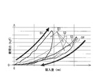
- FIG. 3 is a graph illustrating the relationship between the impact force at room temperature and the amount of intrusion.
- FIG. 4 is a graph illustrating the relationship between the impact force at 70 ° C. and the amount of intrusion.
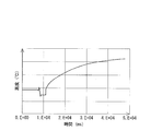
- FIG. 5 is a graph illustrating the change over time of the surface temperature of the test sample.
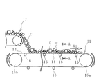
- FIG. 6 is an explanatory view illustrating a conveyor belt line in a simplified manner.
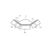
- FIG. 7 is a cross-sectional view taken along the line AA in FIG.
- FIG. 8 is an explanatory diagram showing the speed of the conveyed product when it collides with the conveyor belt.
- the conveyed product C conveyed by another conveyor belt 17 is input to the conveyor belt 11 and conveyed to the conveyance destination by the conveyor belt 11.
- the conveyed product C may be put into the conveyor belt 11 through a hopper or the like.
- the conveyor belt 11 is stretched between pulleys 15a and 15b and is stretched with a predetermined tension.
- the conveyor belt 11 includes a core body layer 12 composed of a core body such as a canvas or a steel cord, and an upper cover rubber 13 and a lower cover rubber 14 sandwiching the core body layer 12. Yes.
- the core body layer 12 is a member that bears tension for tensioning the conveyor belt 11.
- the lower cover rubber 14 is supported by the support roller 16 on the carrier side of the conveyor belt 11, and the upper cover rubber 13 is supported by the support roller 16 on the return side.
- Three support rollers 16 are arranged in the belt width direction on the carrier side of the conveyor belt 11, and the conveyor belt 11 is supported in a concave shape at a predetermined trough angle a by these support rollers 16.
- the driving pulley 15a is rotationally driven, the conveyor belt 11 operates in one direction at a predetermined traveling speed V1.
- the conveyed product S is put on the upper cover rubber 13, loaded on the upper cover rubber 13, and conveyed.
- the conveyor belt 11 and another conveyor belt 17 are arranged with a vertical difference h.
- the conveyed product C is conveyed at a horizontal speed V0 (V0 ⁇ V1).
- V0 the vertical speed of the conveyed product C
- the vertical speed of the conveyed product C is accelerated from zero to V2.
- g is a gravitational acceleration.
- the impact energy E applied to the upper cover rubber 13 is Mgh.
- M the mass of the conveyed product C.
- the upper cover rubber 13 absorbs a predetermined ratio of impact energy E.
- the amount of energy (loss energy E1) absorbed by the upper cover rubber 13 varies depending on the rubber type. Since there is a correlation between the amount of loss energy E1 absorbed by the rubber type and the impact resistance of the rubber type, it is possible to grasp the impact resistance of the rubber type by calculating the loss energy E1. it can.
- the impact test apparatus 1 of the present invention includes an installation base 2 on which a test sample S is installed, an impact imparting body 10 that freely drops the test sample S, a load meter 5, and a displacement meter. 6 and a calculation unit 8.
- a temperature sensor 7 and a temperature regulator 9 are further provided.
- the test sample S is an equivalent of a member that is actually used as an object (upper cover rubber 13) for evaluating impact resistance.
- the impact imparting body 10 it is desirable to include a plurality of types of impact imparting bodies 10a, 10b, 10c, and 10d having different specifications such as the lower end shape and weight. From these plural types of specifications, the impact imparting body 10 having specifications approximate to the conveyed product C that gives an impact to the upper cover rubber 13 in actual use is selected.
- a beam portion 3a extends between the standing frame 3 and a holding mechanism 4 is provided on the beam portion 3a.
- the beam portion 3a can be arbitrarily moved to a height position and fixed.
- the impact applying body 10a detachably held by the holding mechanism 4 is configured to freely fall toward the test sample S installed on the plate-shaped installation table 2 when the holding is released.
- the load cell 5 is installed below the installation table 2 and measures the impact force acting on the test sample S.
- the displacement meter 6 measures the indentation amount H of the impact imparting body 10 a that has collided with the test sample S by free-falling. When the shape of the lower end of the impact imparting body 10a is sharp, the indentation amount H becomes the depth of the wound.
- Measurement data of the load meter 5 and the displacement meter 6 is input to the calculation unit 8. As the calculation unit 8, various computers can be used.
- the temperature sensor 7 measures the surface temperature of the test sample S.
- the surface temperature measured by the temperature sensor 7 is input to the calculation unit 8.
- thermography or the like can be used as the temperature sensor 7, thermography or the like.
- the temperature controller 9 heats or cools the test sample S, and sets the temperature of the test sample S to an arbitrary temperature.
- the temperature controller 9 installed on the lower surface of the installation table 2 heats or cools the installation table 2 to indirectly heat or cool the test sample S and set it to an arbitrary temperature.
- a constant temperature case or the like in which the entire test apparatus is covered with a cover and the inside of the cover can be set to an arbitrary atmospheric temperature can be used.
- the test sample S is installed on the installation base 2 illustrated in FIG.
- An appropriate impact imparting body 10a that approximates the actual use condition of the conveyor belt 11 is selected from a plurality of types of impact imparting bodies 10 and attached to the holding mechanism 4. Further, the impact applying body 10 is set to an appropriate height position (for example, a position at a height h from the surface of the test sample S) by moving the beam portion 3a.
- the test sample S is set to a predetermined temperature by the temperature controller 9.
- the holding by the holding mechanism 4 with respect to the impact imparting body 10 is released, and the impact imparting body 10 is freely dropped and collided with the test sample S.
- M is a known mass of the impact imparting body 10.
- the load force 5 sequentially measures the impact force acting on the test sample S. Further, the displacement amount H of the impact imparting body 10 with respect to the test sample S illustrated in FIG.
- the impact force measured by the load meter 5 and the indentation amount H measured by the displacement meter 6 are input to the calculation unit 8.
- FIG. 3 shows measurement data when four types of test samples S (S1 to S4) are tested at room temperature under the same test conditions (when the test sample S is about 20 ° C.).
- FIG. 4 shows measurement data when testing is performed at 70 ° C. by changing only the temperatures of four types of test samples S (S1 to S4).
- the calculation unit 8 calculates the loss energy E1 absorbed by the test sample S when the impact imparting body 10 and the test sample S collide based on the input measurement data. 3 and 4, the range of the data curve of each test sample S that goes up to the right indicates the impact force and the amount of intrusion H from when the impact imparting body 10 contacts the test sample S to the deepest indentation. Shows the relationship. Therefore, the intrusion energy E2 can be calculated by integrating this data curve in this range.
- the range to the left of these data curves shows the relationship between the impact force and the amount of indentation H until the impact imparting body 10 retreats from the test sample S to the deepest position and then rebounds from the test sample 10. ing. Therefore, the repulsive energy E3 can be calculated by integrating this data curve in this range.
- the ratio (E1 / E) absorbed by the test sample S as the loss energy E1 out of the impact energy E applied by the impact applying body 10 can be grasped.
- This ratio (E1 / E) varies depending on the rubber type (particularly viscoelastic properties) and is closely related to the impact resistance of the rubber. Therefore, if a database in which the correlation data between the ratio (E1 / E) and the impact resistance of the rubber is collected is created, the object (conveyor belt) is based on the database and the calculated loss energy E1. 11) It is possible to accurately grasp the impact resistance consistent with the actual use.
- the loss energy E1 depends on the temperature of the test sample S. Therefore, it is preferable to obtain the respective measurement data described above by performing the impact test while changing the temperature of the test sample S to a plurality of levels, and grasp the temperature dependence of the loss energy E. That is, a database may be created for each temperature of the test sample S. Thereby, by using the database under the temperature condition that matches the usage environment temperature of the conveyor belt 11, the impact resistance that matches the actual use of the object (conveyor belt 11) can be grasped more accurately.
- the surface temperature of the test sample S immediately after the impact imparting body 10 bounces can be sequentially measured by the temperature sensor 7.
- the surface temperature measured by the temperature sensor 7 is input to the calculation unit 8. As illustrated in FIG. 5, the surface temperature of the test sample at room temperature is measured, and the change with time can be grasped.
- the calculation unit 8 calculates thermal energy E4 generated in the test sample S when the impact imparting body 10 and the test sample S collide based on the measured surface temperature and the intrusion amount H.
- the rising temperature ⁇ T (maximum rising temperature ⁇ T) of the test sample S due to the collision with the impact imparting body 10 is found.
- the specific heat c of the test sample S is known in advance.
- the mass m of the test sample S whose temperature has increased is calculated as follows, for example.
- the indentation amount H of the impact imparting body 10 is measured by the displacement meter 6. Since the shape of the impact imparting body 10 is known in advance, for example, the maximum cross-sectional area and the maximum amount of intrusion of the portion of the impact imparting body 10 that is invaded into the test sample S when it is most deeply invaded.
- the volume V calculated by multiplying is taken as the volume V of the test sample S whose temperature has increased. Since the specific gravity ⁇ of the test sample S is known in advance, the mass m of the test sample S whose temperature has increased can be calculated by multiplying the volume V and the specific gravity ⁇ .
- the thermal energy E4 can be calculated by multiplying the mass m, the specific heat c, and the rising temperature ⁇ T.
- the ratio (E4 / E) converted into the thermal energy E4 by the test sample S out of the impact energy E applied by the impact applying body 10 that has been freely dropped can be grasped.
- This ratio (E4 / E) varies depending on the rubber type (particularly the viscoelastic property among the rubber properties), and is closely related to the impact resistance of the rubber. Therefore, if a database in which the correlation data between the ratio (E4 / E) and the impact resistance of the rubber is collected is created, the object (conveyor belt) is based on the database and the calculated thermal energy E4. 11) It is possible to accurately grasp the impact resistance consistent with the actual use.
- the upper cover rubber 13 of the conveyor belt 11 is taken as an example of an object to be evaluated for impact resistance, but the object is not limited to this.
- the target object may be any object that is used under conditions in which various collision objects such as stones and earth and sand collide and bounce and are used under conditions in which the collision object does not easily penetrate.
- a rubber member such as a tire tread rubber, the core body layer 12 of the conveyor belt 11, and the like can be exemplified as objects.
Landscapes
- Physics & Mathematics (AREA)
- General Physics & Mathematics (AREA)
- General Health & Medical Sciences (AREA)
- Chemical & Material Sciences (AREA)
- Analytical Chemistry (AREA)
- Biochemistry (AREA)
- Life Sciences & Earth Sciences (AREA)
- Health & Medical Sciences (AREA)
- Immunology (AREA)
- Pathology (AREA)
- Engineering & Computer Science (AREA)
- Mechanical Engineering (AREA)
- Investigating Strength Of Materials By Application Of Mechanical Stress (AREA)
Abstract
Description
2 設置台
3 フレーム
3a 梁部
4 保持機構
5 荷重計
6 変位計
7 温度センサ
8 演算部
9 温度調節器
10 衝撃付与体
11 コンベヤベルト
12 心体層
13 上カバーゴム
14 下カバーゴム
15a、15b プーリ
16 支持ローラ
17 別のコンベヤベルト
S(S1、S2、S3、S4) 試験サンプル
Claims (7)
- 試験サンプルに衝撃付与体を自由落下させて衝突させる衝撃試験方法において、
自由落下させた前記衝撃付与体が前記試験サンプルに衝突した際の前記試験サンプルに作用する衝撃力と、前記試験サンプルに対する前記衝撃付与体の陥入量とを測定し、この測定した衝撃力と陥入量とに基づいて、前記衝撃付与体と前記試験サンプルとが衝突した際に前記試験サンプルにより吸収された損失エネルギを算出することを特徴とする衝撃試験方法。 - 前記衝撃付与体が衝突した前記試験サンプルの表面温度を測定し、この測定した表面温度と前記陥入量とに基づいて、前記衝撃付与体と前記試験サンプルとが衝突した際に前記試験サンプルに発生した熱エネルギを算出する請求項1に記載の衝撃試験方法。
- 温度条件を異ならせて前記衝撃試験を行う請求項1または2に記載の衝撃試験方法。
- 前記試験サンプルとしてゴムを用いる請求項1~3のいずれかに記載の衝撃試験方法。
- 試験サンプルが設置される設置台と、この設置台に設置された前記試験サンプルに対して自由落下させる衝撃付与体とを備えた衝撃試験装置において、
前記試験サンプルに作用する衝撃力を測定する荷重計と、前記試験サンプルに対する前記衝撃付与体の陥入量を測定する変位計と、前記荷重計および前記変位計の測定データが入力される演算部とを備えて、
自由落下させた前記衝撃付与体が前記試験サンプルに衝突した際に前記荷重計と前記変位計のそれぞれにより測定した衝撃力と陥入量とに基づいて、前記演算部により、前記衝撃付与体と前記試験サンプルとが衝突した際に前記試験サンプルにより吸収された損失エネルギが算出される構成にしたことを特徴とする衝撃試験装置。 - 前記試験サンプルの表面温度を測定する温度センサを有し、この温度センサにより測定された前記衝撃付与体が衝突した前記試験サンプルの表面温度と前記陥入量とに基づいて、前記演算部により、前記衝撃付与体と前記試験サンプルとが衝突した際に前記試験サンプルに発生した熱エネルギが算出される構成にした請求項5に記載の衝撃試験装置。
- 前記試験サンプルの温度を変化させる温度調節器を有する請求項5または6に記載の衝撃試験装置。
Priority Applications (4)
| Application Number | Priority Date | Filing Date | Title |
|---|---|---|---|
| DE112017002128.6T DE112017002128B4 (de) | 2016-04-22 | 2017-02-22 | Schlagprüfungsverfahren |
| AU2017252993A AU2017252993B2 (en) | 2016-04-22 | 2017-02-22 | Impact test method and device |
| US16/095,672 US10928284B2 (en) | 2016-04-22 | 2017-02-22 | Impact test method and device in which an impact application member is caused to fall freely onto and collide with a test sample |
| CN201780022925.8A CN108885160B (zh) | 2016-04-22 | 2017-02-22 | 冲击试验方法以及装置 |
Applications Claiming Priority (2)
| Application Number | Priority Date | Filing Date | Title |
|---|---|---|---|
| JP2016-085950 | 2016-04-22 | ||
| JP2016085950A JP6743472B2 (ja) | 2016-04-22 | 2016-04-22 | 衝撃試験方法および装置 |
Publications (1)
| Publication Number | Publication Date |
|---|---|
| WO2017183283A1 true WO2017183283A1 (ja) | 2017-10-26 |
Family
ID=60115790
Family Applications (1)
| Application Number | Title | Priority Date | Filing Date |
|---|---|---|---|
| PCT/JP2017/006495 Ceased WO2017183283A1 (ja) | 2016-04-22 | 2017-02-22 | 衝撃試験方法および装置 |
Country Status (6)
| Country | Link |
|---|---|
| US (1) | US10928284B2 (ja) |
| JP (1) | JP6743472B2 (ja) |
| CN (1) | CN108885160B (ja) |
| AU (1) | AU2017252993B2 (ja) |
| DE (1) | DE112017002128B4 (ja) |
| WO (1) | WO2017183283A1 (ja) |
Cited By (2)
| Publication number | Priority date | Publication date | Assignee | Title |
|---|---|---|---|---|
| CN111157373A (zh) * | 2019-12-31 | 2020-05-15 | 同济大学 | 评估汽车电池多孔结构吸能垫性能的落锤冲击测试法 |
| CN114152399A (zh) * | 2021-12-03 | 2022-03-08 | 上海煤科检测技术有限公司 | 一种输送带冲击性能试验方法 |
Families Citing this family (13)
| Publication number | Priority date | Publication date | Assignee | Title |
|---|---|---|---|---|
| JP6743473B2 (ja) * | 2016-04-22 | 2020-08-19 | 横浜ゴム株式会社 | ゴムの選定方法 |
| JP6819242B2 (ja) * | 2016-11-24 | 2021-01-27 | 横浜ゴム株式会社 | コンベヤベルトでのループコイルの埋設深さの設定方法およびコンベヤベルトの製造方法 |
| GB201804930D0 (en) * | 2018-03-27 | 2018-05-09 | Engenuity Ltd | Drop towers |
| CN109085054A (zh) * | 2018-08-30 | 2018-12-25 | 吉林大学 | 一种测量材料温度冲击性能的试验装置 |
| CN111024353B (zh) * | 2019-12-16 | 2021-12-21 | 首钢集团有限公司 | 一种冲击力测试装置及方法 |
| KR102354437B1 (ko) * | 2020-07-16 | 2022-01-25 | 한국생산기술연구원 | 소재 코팅층 변화 검출용 반복 충격시험장치 |
| CN111999193A (zh) * | 2020-09-04 | 2020-11-27 | 广州特种承压设备检测研究院 | 硬度的测试方法 |
| CN113340616B (zh) * | 2021-07-02 | 2024-04-30 | 江苏徐工工程机械研究院有限公司 | 应急救援车辆作业性能试验装置及试验方法 |
| CN113624589B (zh) * | 2021-08-16 | 2022-05-17 | 沭阳县润丰木业制品厂 | 一种智能木材测量支架 |
| CN114923954B (zh) * | 2022-05-18 | 2024-08-23 | 中国矿业大学(北京) | 一种物料破碎过程耗散热能在线测定方法及系统 |
| CN116952705B (zh) * | 2023-09-19 | 2024-02-20 | 中铁十七局集团第五工程有限公司 | 一种结构仿生玄武岩纤维增强复合材料抗冲击检测装置 |
| KR102747513B1 (ko) * | 2023-12-14 | 2024-12-27 | 국립목포대학교산학협력단 | 단열구조체 낙하 시험장치 |
| KR102747512B1 (ko) * | 2023-12-18 | 2024-12-30 | 국립목포대학교산학협력단 | 단열구조체 낙하 시험방법 |
Citations (3)
| Publication number | Priority date | Publication date | Assignee | Title |
|---|---|---|---|---|
| JPH10260123A (ja) * | 1997-03-18 | 1998-09-29 | Bridgestone Corp | 弾性体の物性試験装置 |
| JP2012189533A (ja) * | 2011-03-14 | 2012-10-04 | Yokohama Rubber Co Ltd:The | コンベヤベルトの衝撃試験装置および方法 |
| WO2016042999A1 (ja) * | 2014-09-16 | 2016-03-24 | 横浜ゴム株式会社 | 衝撃試験装置および方法 |
Family Cites Families (24)
| Publication number | Priority date | Publication date | Assignee | Title |
|---|---|---|---|---|
| US4313337A (en) * | 1980-03-17 | 1982-02-02 | The Dow Chemical Company | Apparatus for evaluating the impact resistance of synthetic resinous products |
| US4331026A (en) * | 1980-07-14 | 1982-05-25 | The Boeing Company | Indenter-type hardness testing apparatus |
| DE3149986C2 (de) * | 1981-12-17 | 1985-05-23 | Hahn, Ortwin, Prof.Dr.-Ing., 4790 Paderborn | Prüfverfahren und Vorrichtung zur Bestimmung von Bruchkennwerten von stoßartig beanspruchten Werkstoffen bzw. Konstruktionselementen |
| US4565089A (en) * | 1984-06-18 | 1986-01-21 | Nabisco Brands, Inc. | Consistometer |
| JPH02257031A (ja) * | 1989-03-30 | 1990-10-17 | Mitsubishi Electric Corp | 衝撃試験装置 |
| CN2299316Y (zh) * | 1997-04-21 | 1998-12-02 | 长春科技大学 | 金刚石单晶及复合片冲击破碎能测定仪 |
| CN1258676C (zh) * | 2001-12-30 | 2006-06-07 | 宝山钢铁股份有限公司 | 金属薄板抗凹性评估方法及装置 |
| US7320242B2 (en) * | 2002-03-12 | 2008-01-22 | The University Of Akron | Tensile impact apparatus |
| US7254840B2 (en) * | 2005-03-21 | 2007-08-14 | Honda Motor Co., Ltd. | Impact and/or vibration absorbent material and protective glove making use thereof |
| JP2008224632A (ja) | 2007-03-16 | 2008-09-25 | Jfe Steel Kk | 落錘式衝撃試験機を用いた衝撃吸収エネルギーの測定方法および落錘式衝撃試験機 |
| CN101509856B (zh) * | 2008-12-30 | 2011-03-23 | 南京理工大学 | 一种多功能柔性复合材料冲击试验装置 |
| CN101776511A (zh) * | 2010-01-29 | 2010-07-14 | 天津大学 | 微纳米薄膜冲击力学性能落锤测量装置 |
| JP5486412B2 (ja) * | 2010-06-07 | 2014-05-07 | 横浜ゴム株式会社 | コンベヤベルトの耐衝撃性の評価システムおよび評価方法 |
| CN103238054A (zh) * | 2010-09-15 | 2013-08-07 | 美国弗劳恩霍夫股份公司 | 用于检测聚合物中的交联的方法和装置 |
| ES2364213B1 (es) * | 2011-03-08 | 2012-03-23 | Instituto Tecnológico Del Embalaje, Transporte Y Log�?Stica | M�?quina de ensayo de material de amortiguamiento de embalajes. |
| JP5834486B2 (ja) * | 2011-05-18 | 2015-12-24 | 横浜ゴム株式会社 | コンベヤベルトの評価装置および評価方法 |
| CN102393289B (zh) * | 2011-12-05 | 2013-08-21 | 北京神州腾耀通信技术有限公司 | 一种钢球跌落试验机 |
| CN104535407A (zh) | 2014-12-25 | 2015-04-22 | 陕西科技大学 | 高速冲击条件下二维多孔材料缓冲性能的测定方法 |
| CN104833596A (zh) * | 2015-05-09 | 2015-08-12 | 青岛双凌科技设备有限公司 | 一种输送带冲击强度试验机 |
| CZ306556B6 (cs) * | 2015-06-23 | 2017-03-08 | České Vysoké Učení Technické V Praze, Fakulta Strojní, Ústav Materiálového Inženýrství | Indentační hlavice, instrumentovaný měřící systém a způsob stanovení mechanických vlastností materiálů indentační metodou |
| JP6547545B2 (ja) * | 2015-09-24 | 2019-07-24 | 横浜ゴム株式会社 | コンベヤベルトの摩耗状態把握方法 |
| JP6743473B2 (ja) * | 2016-04-22 | 2020-08-19 | 横浜ゴム株式会社 | ゴムの選定方法 |
| US10436690B2 (en) * | 2016-06-24 | 2019-10-08 | Wells Lamont Industry Group Llc | Glove impact resistance testing |
| JP6794684B2 (ja) * | 2016-07-12 | 2020-12-02 | 横浜ゴム株式会社 | ゴムの耐摩耗性評価方法 |
-
2016
- 2016-04-22 JP JP2016085950A patent/JP6743472B2/ja active Active
-
2017
- 2017-02-22 WO PCT/JP2017/006495 patent/WO2017183283A1/ja not_active Ceased
- 2017-02-22 CN CN201780022925.8A patent/CN108885160B/zh active Active
- 2017-02-22 AU AU2017252993A patent/AU2017252993B2/en not_active Ceased
- 2017-02-22 US US16/095,672 patent/US10928284B2/en not_active Expired - Fee Related
- 2017-02-22 DE DE112017002128.6T patent/DE112017002128B4/de active Active
Patent Citations (3)
| Publication number | Priority date | Publication date | Assignee | Title |
|---|---|---|---|---|
| JPH10260123A (ja) * | 1997-03-18 | 1998-09-29 | Bridgestone Corp | 弾性体の物性試験装置 |
| JP2012189533A (ja) * | 2011-03-14 | 2012-10-04 | Yokohama Rubber Co Ltd:The | コンベヤベルトの衝撃試験装置および方法 |
| WO2016042999A1 (ja) * | 2014-09-16 | 2016-03-24 | 横浜ゴム株式会社 | 衝撃試験装置および方法 |
Cited By (2)
| Publication number | Priority date | Publication date | Assignee | Title |
|---|---|---|---|---|
| CN111157373A (zh) * | 2019-12-31 | 2020-05-15 | 同济大学 | 评估汽车电池多孔结构吸能垫性能的落锤冲击测试法 |
| CN114152399A (zh) * | 2021-12-03 | 2022-03-08 | 上海煤科检测技术有限公司 | 一种输送带冲击性能试验方法 |
Also Published As
| Publication number | Publication date |
|---|---|
| US20190128786A1 (en) | 2019-05-02 |
| CN108885160B (zh) | 2021-07-13 |
| JP2017194406A (ja) | 2017-10-26 |
| AU2017252993B2 (en) | 2020-03-19 |
| DE112017002128T5 (de) | 2019-01-03 |
| CN108885160A (zh) | 2018-11-23 |
| AU2017252993A1 (en) | 2018-10-25 |
| DE112017002128B4 (de) | 2025-08-14 |
| JP6743472B2 (ja) | 2020-08-19 |
| US10928284B2 (en) | 2021-02-23 |
Similar Documents
| Publication | Publication Date | Title |
|---|---|---|
| WO2017183283A1 (ja) | 衝撃試験方法および装置 | |
| EP3290903B1 (en) | Abrasive wear test device and method | |
| JP6679824B2 (ja) | 衝撃試験装置および方法 | |
| JP2016090417A (ja) | 摩耗試験装置および方法 | |
| JP2016061597A (ja) | 摩耗試験装置および方法 | |
| JP6536296B2 (ja) | コンベヤベルトの耐衝撃性評価方法 | |
| CN109073521B (zh) | 橡胶的选定方法 | |
| JP6503694B2 (ja) | 衝撃試験装置および方法 | |
| JP2019060711A (ja) | コンベヤベルトの寿命予測方法 | |
| KR101949348B1 (ko) | 물체수송장치 |
Legal Events
| Date | Code | Title | Description |
|---|---|---|---|
| ENP | Entry into the national phase |
Ref document number: 2017252993 Country of ref document: AU Date of ref document: 20170222 Kind code of ref document: A |
|
| 121 | Ep: the epo has been informed by wipo that ep was designated in this application |
Ref document number: 17785628 Country of ref document: EP Kind code of ref document: A1 |
|
| 122 | Ep: pct application non-entry in european phase |
Ref document number: 17785628 Country of ref document: EP Kind code of ref document: A1 |
|
| WWG | Wipo information: grant in national office |
Ref document number: 112017002128 Country of ref document: DE |