WO2017183237A1 - キーレンチ - Google Patents
キーレンチ Download PDFInfo
- Publication number
- WO2017183237A1 WO2017183237A1 PCT/JP2017/000282 JP2017000282W WO2017183237A1 WO 2017183237 A1 WO2017183237 A1 WO 2017183237A1 JP 2017000282 W JP2017000282 W JP 2017000282W WO 2017183237 A1 WO2017183237 A1 WO 2017183237A1
- Authority
- WO
- WIPO (PCT)
- Prior art keywords
- key
- hole
- tapered
- key portion
- taper angle
- Prior art date
Links
Images


Classifications
-
- B—PERFORMING OPERATIONS; TRANSPORTING
- B25—HAND TOOLS; PORTABLE POWER-DRIVEN TOOLS; MANIPULATORS
- B25B—TOOLS OR BENCH DEVICES NOT OTHERWISE PROVIDED FOR, FOR FASTENING, CONNECTING, DISENGAGING OR HOLDING
- B25B23/00—Details of, or accessories for, spanners, wrenches, screwdrivers
- B25B23/02—Arrangements for handling screws or nuts
- B25B23/08—Arrangements for handling screws or nuts for holding or positioning screw or nut prior to or during its rotation
- B25B23/10—Arrangements for handling screws or nuts for holding or positioning screw or nut prior to or during its rotation using mechanical gripping means
- B25B23/105—Arrangements for handling screws or nuts for holding or positioning screw or nut prior to or during its rotation using mechanical gripping means the gripping device being an integral part of the driving bit
- B25B23/108—Arrangements for handling screws or nuts for holding or positioning screw or nut prior to or during its rotation using mechanical gripping means the gripping device being an integral part of the driving bit the driving bit being a Philips type bit, an Allen type bit or a socket
-
- B—PERFORMING OPERATIONS; TRANSPORTING
- B25—HAND TOOLS; PORTABLE POWER-DRIVEN TOOLS; MANIPULATORS
- B25B—TOOLS OR BENCH DEVICES NOT OTHERWISE PROVIDED FOR, FOR FASTENING, CONNECTING, DISENGAGING OR HOLDING
- B25B13/00—Spanners; Wrenches
- B25B13/48—Spanners; Wrenches for special purposes
- B25B13/488—Spanners; Wrenches for special purposes for connections where two parts must be turned in opposite directions by one tool
-
- B—PERFORMING OPERATIONS; TRANSPORTING
- B25—HAND TOOLS; PORTABLE POWER-DRIVEN TOOLS; MANIPULATORS
- B25B—TOOLS OR BENCH DEVICES NOT OTHERWISE PROVIDED FOR, FOR FASTENING, CONNECTING, DISENGAGING OR HOLDING
- B25B15/00—Screwdrivers
- B25B15/001—Screwdrivers characterised by material or shape of the tool bit
- B25B15/004—Screwdrivers characterised by material or shape of the tool bit characterised by cross-section
- B25B15/008—Allen-type keys
Definitions
- the present invention relates to a key wrench.
- FIG. 1 cross-sectional view
- the hexagonal hole 2 'of the fastening member 1' and the key portion of the key wrench 5 ' are described.
- the cross-sectional shape of the key portion is smaller than the cross-sectional shape of the hexagonal hole 2 '.
- the corner 6 'of the key portion and the surface 3' defining the hexagonal hole 2 ' come into contact with each other in a small area.
- a large stress concentration occurs in the portion corresponding to the small area.
- the surface 3 ′ defining the hexagonal hole 2 ′ is deformed by the corner 6 ′ of the key portion.
- FIG. 2 shows an example in which the shape of the surface 3 'defining the hexagonal hole 2' is changed to the circular shape indicated by the code 3 '' as a result of fixing or removing the fastening member 1 'a plurality of times. It is done.
- Patent Document 1 describes a wrench.
- the wrench described in Patent Document 1 includes an operating unit and an operating unit.
- the action portion has a hexagonal pyramidal shape that narrows toward the tip, and the side surface of the action portion is inclined with respect to the axis of the action portion.
- An object of the present invention is to provide a key wrench in which the deformation of the surface of the hole is suppressed and the occurrence of an excessive cam out load is suppressed.
- the key wrench in some embodiments, when defining N as any natural number of 3 or more, comprises a key portion engageable in an N-square shaped hole and a proximal end portion.
- the key portion includes N side surfaces including a first side surface, a second side surface, and an Nth side surface.
- the first side surface is a tapered surface
- the Nth side surface is a non-tapered surface.
- the key portion may include a third side.
- at least one of the second side surface and the third side surface may be a tapered surface.
- the side surfaces other than the first side surface, the second side surface, and the third side surface may be non-tapered surfaces.
- the second side surface may be a tapered surface.
- the third side surface may be a non-tapered surface.
- the second side surface may be a tapered surface.
- the first side surface, which is a tapered surface, and the second side surface, which is a tapered surface, may be adjacent to each other.
- the taper angle of the first side surface may be 1 ° or more and 2.5 ° or less.
- a cross section perpendicular to the longitudinal axis of the key portion is two or more sides overlapping any one of N sides constituting a virtual regular N-gon, and the virtual regular N-gon It may include at least one side located outward.
- the key wrench in some embodiments, when defining N as any natural number of 3 or more, comprises a key portion engageable in an N-square shaped hole and a proximal end portion.
- the key portion includes N side surfaces including a first side surface, a second side surface, and an Nth side surface.
- the first side surface includes a first tapered surface inclined with respect to a first axis which is a longitudinal central axis of the key portion.
- An Nth taper angle which is an angle formed between the Nth side surface and the first axis is smaller than a first taper angle which is an angle formed between the first side surface and the first axis.
- FIG. 1 is a schematic cross-sectional view showing how stress concentration is generated on the surface defining a hole by use of a conventional key wrench.
- FIG. 2 is a schematic cross-sectional view showing a state in which the shape of the surface defining the hole has largely changed by the use of the conventional key wrench.
- FIG. 3 is a view for explaining the longitudinal central axis of the key portion, and is a cross-sectional view perpendicular to the longitudinal direction of the key portion.
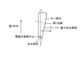
- FIG. 4 is a view for explaining the longitudinal central axis of the key portion and the taper angle, and is a longitudinal sectional view of the key portion.
- FIG. 5 is a diagram for explaining matters recognized by the inventor.
- FIG. 6 is a schematic perspective view of the key wrench in the embodiment.
- FIG. 6 is a schematic perspective view of the key wrench in the embodiment.
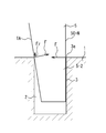
- FIG. 7 is a longitudinal sectional view showing a state in which the key portion of the key wrench 5 is inserted into the hole.
- 8 is a cross-sectional view of the key wrench at plane A in FIG.
- FIG. 9 is a bottom view schematically showing a modified example of the key wrench in the embodiment.
- FIG. 10A is a schematic bottom view of the key portion of the key wrench in the first example.
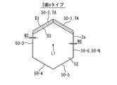
- FIG. 10B is a schematic bottom view of the key portion of the key wrench in the second example.
- FIG. 10C is a schematic bottom view of the key portion of the key wrench in the third example.
- FIG. 10D is a schematic bottom view of the key portion of the key wrench in the fourth example.
- FIG. 10E is a schematic bottom view of the key portion of the key wrench in the fifth example.
- FIG. 10A is a schematic bottom view of the key portion of the key wrench in the first example.
- FIG. 10B is a schematic bottom view of the key portion of the key wrench in the second example.
- FIG. 10F is a schematic bottom view of the key portion of the key wrench in a sixth example.
- FIG. 11 is a longitudinal sectional view showing an application example of a key wrench.
- FIG. 12 is a schematic perspective view showing an application example of a key wrench.
- FIG. 13 is a longitudinal sectional view showing an outline of the experimental apparatus.
- FIG. 14 is a diagram showing an analysis result.
- FIG. 14 is a graph showing the relationship between the taper angle and the torque at which the hole is broken.
- FIG. 15 is a diagram showing an analysis result.
- FIG. 15 is a graph showing the relationship between the torque and the cam out load.
- FIG. 16 is a diagram showing an analysis result.
- FIG. 11 is a longitudinal sectional view showing an application example of a key wrench.
- FIG. 12 is a schematic perspective view showing an application example of a key wrench.
- FIG. 13 is a longitudinal sectional view showing an outline of the experimental apparatus.
- FIG. 14 is a diagram showing an analysis result.
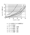
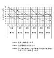
- FIG. 16 is a graph showing the relationship between the taper angle, the torque at which the hole starts to be deformed, the torque at which the hole is broken, and the torque applied until the cam out load reaches 10 kgf for the first to sixth examples. It is.
- FIG. 17 is a diagram showing experimental results.
- FIG. 17 is a graph showing the relationship between the number of tapered surfaces and the torque at which holes are broken.
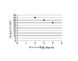
- FIG. 18 is a diagram showing experimental results.
- FIG. 18 is a graph showing the relationship between the taper angle and the torque at which the hole is broken.
- the direction from the distal end (free end) of the key portion of the key wrench toward the proximal direction is defined as the “first direction”.
- “upper” corresponds to the first direction. That is, in the present specification, in reality, the “first direction” is defined to be the upper side even when the first direction and the vertically upward direction do not coincide with each other.
- “lower (second direction)” means a direction opposite to “upper (first direction)”.
- the longitudinal central axis L1 of the key portion of the key wrench is interpreted in light of general technical common knowledge.
- the longitudinal central axis L1 of the key portion is interpreted as follows: Ru. (1)
- the longitudinal central axis L1 of the key portion is perpendicular to the cross section of the regular polygon and is positive It means an axis passing through the center of the polygonal cross section.
- the distance between the side corresponding to each non-tapered surface and the longitudinal central axis L1 is D.
- the taper angle of the side surface of the key portion means the angle ⁇ between the side surface and the longitudinal axis (longitudinal central axis L1) of the key portion, as shown in FIG. . More specifically, the angle ⁇ is a line intersecting the central axis L1 among the normals of the tapered surface (hereinafter referred to as “first normal”), an extension of the central axis L1, and the first normal And means a facing angle to the first normal in a triangle formed by the intersection of the plane including the extension line and the tapered surface. (See Figure 4)
- FIG. 5 is a figure for demonstrating the matter recognized by the inventor, Comprising: It is not a figure which shows a well-known problem or subject.
- FIG. 6 is a schematic perspective view of the key wrench 5 in the embodiment.
- FIG. 7 is a longitudinal sectional view showing a state in which the key portion 5-2 of the key wrench 5 is inserted into the hole 2.
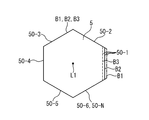
- FIG. 8 is a cross-sectional view (a cross-sectional view in a cross section perpendicular to the longitudinal central axis L1 of the key wrench) of the key wrench 5 in the plane A in FIG.
- the key wrench 5 comprises a proximal end portion 5-1 and a key portion 5-2.
- the proximal end portion 5-1 is a portion held by an operator, a tool or a machine.
- the key portion 5-2 is a portion capable of engaging in an N-square shaped hole when N is defined as a natural number of 3 or more.
- a hexagon, a regular hexagon, a hexagonal hole, a sixth side, and a sixth taper angle are respectively N square, regular N square, N square hole, N side, N taper It is possible to generalize the explanation by replacing it with the angle.
- the proximal end portion 5-1 and the key portion 5-2 are connected via a cross section B1 (a cross section perpendicular to the longitudinal central axis L1).
- the cross section B1 is a hexagon but not a regular hexagon.
- the distal portion of the proximal end portion 5-1 may be provided with a transition portion 58 in which the cross-sectional area gradually decreases (continuously decreases in cross-sectional area) toward the distal end side.
- the distal end of the transition portion 58 is connected to the key portion 5-2.
- the presence of the transition portion 58 suppresses the occurrence of a large stress concentration when torque is transmitted between the key portion 5-2 having a small cross-sectional area and the proximal portion 5-1 having a large cross-sectional area. Ru.
- the proximal end of the key portion 5-2 of the key wrench 5 is connected to the proximal end portion 5-1, and the distal end of the key portion 5-2 is a free end 52.
- the key portion 5-2 includes first to sixth side surfaces 50-1 to 50-6. That is, the key portion 5-2 has a first side 50-1, a second side 50-2, a third side 50-3, a fourth side 50-4, a fifth side 50-5, and a sixth side 50-6. Equipped with The first side surface 50-1 includes a tapered surface TA (first tapered surface) inclined with respect to a first axis which is the longitudinal central axis L1.
- the first taper angle which is the angle between the first side surface 50-1 and the first axis, is preferably 1 degree or more.
- the sixth side surface 50-6 of the key portion 5-2 is a non-tapered surface.
- the sixth taper angle which is the angle between the sixth side surface 50-6 and the longitudinal central axis L1 (first axis) is 0 degree.
- a non-taper surface is a surface whose taper angle is less than 1 degree or less than 0.5 degree. May be included.
- the key portion 5-2 of the key wrench 5 in the embodiment includes a first side surface which is a tapered surface and a sixth side surface which is a non-tapered surface.
- the taper angle of the sixth side is smaller than the taper angle of the first side.
- the key portion since the key portion includes the side surface having a taper angle of 0 degree or a small angle, as shown in FIG. 7, it is possible to reduce the total value of the cam out load Fz.
- FIG. 8 is a cross-sectional view of the key wrench 5 at plane A in FIG.
- the cross section B2 of the key wrench 5 in the plane A is a hexagonal but non-regular hexagon.
- the cross section B2 is a cross section corresponding to, for example, a portion in contact with the opening edge 3a (see FIG. 7) of the hole 2 when the key portion 5-2 is inserted into the hole 2.
- a cross section B1 showing the base end face of the key portion 5-2 of the key wrench 5 and a cross section B3 showing the free end of the key portion 5-2 are shown for reference.
- the cross section B2 is a cross section located between the cross section B1 and the cross section B3.
- the first side surface 50-1 which is a tapered surface, is a surface in which the distance from the longitudinal central axis L1 decreases as it goes to the tip (free end). Further, the first side surface 50-1 is a surface in which the distance from the side surface (the fourth side surface 50-4) opposed to the first side surface 50-1 becomes smaller toward the tip.
- the taper angle of the sixth side surface 50-6 which is a non-tapered surface, is 0 degree, the distance from the longitudinal central axis L1 of the sixth side surface 50-6 is directed to the tip (free end) It does not change as you go. In the example shown in FIG.
- the angle between the first side surface 50-1 and the side surface facing the first side surface (the fourth side surface 50-4) is the sixth side surface 50-6, and the sixth side surface 50-6. 6 larger than the angle between the side surface opposite to the side surface (third side surface 50-3).
- the tapered surface, the first side surface 50-1, and the longitudinal central axis L1 The distance between them is larger than the distance between the sixth side surface 50-6 and the longitudinal central axis L1. Therefore, when the key portion 5-2 is inserted into the hole 2, the tapered first side surface 50-1 more reliably contacts the opening end edge 3a of the hole.
- the distance between the first side surface 50-1 which is a tapered surface and the side surface facing the first side surface (the fourth side surface 50-4) is the sixth side surface 50-6 and the sixth side surface. It is larger than the distance between the side surface and the opposite side surface (third side surface 50-3). For this reason, when the key portion 5-2 is inserted into the hole 2, the first side surface 50-1 (or the first side surface 50-1 and the fourth side surface 50-4), which are tapered surfaces, is more surely a hole.
- the first side surface 50-1 is located outside the virtual regular hexagon defined by the second side surface 50-2 to the sixth side surface 50-6.
- the cross section perpendicular to the longitudinal axis (longitudinal central axis L1) of the key portion 5-2 has two or more sides or three overlapping one of the six sides forming the virtual regular hexagon.
- One or more sides see 50-2, 50-3, 50-4, 50-5, 50-6 in FIG. 8) and at least one side (see FIG. 8) outside the imaginary hexagon. See the solid line corresponding to 50-1 in
- the first side surface 50-1 is an inner side of a virtual regular hexagon defined by the second side surface 50-2 to the sixth side surface 50-6. It may be located at or outside. In the example shown in FIG. 8, in the cross section B3, the first side surface 50-1 is located on an imaginary regular hexagon defined by the second side surface 50-2 to the sixth side surface 50-6. In other words, in the example shown in FIG. 8, the cross section B3 corresponding to the free end of the key portion 5-2 is a regular hexagon.
- all of the second side surface 50-2 to the fifth side surface 50-5 are non-tapered surfaces, but among the second side surface 50-2 to the fifth side surface 50-5, One, two, three or four may be tapered surfaces.
- FIG. 9 is a bottom view schematically showing a modified example of the key wrench 5 in the embodiment.
- the first side surface 50-1 is a tapered surface in which the distance from the longitudinal central axis L1 decreases toward the tip.
- the second side surface 50-2 to the sixth side surface 50-6 are also surfaces that decrease in distance from the longitudinal central axis L1 toward the tip.
- the taper angle (tilt angle) of the sixth side surface 50-6 is smaller than the taper angle (tilt angle) of the first side surface 50-1 which is a tapered surface.
- the taper angle of the sixth side 50-6 is less than 1 degree or less than 0.5 degrees, the sixth side 50-6 is considered herein to be a non-tapered surface.
- the degree to which the distance between the sixth side surface 50-6 and the side surface facing the sixth side surface 50-6 decreases toward the tip
- the distance between the first side surface 50-1 and the side surface facing the first side surface 50-1 is smaller than the degree of decrease toward the tip.
- the first taper angle which is the angle between the first side surface 50-1 and the longitudinal central axis L1 (first axis)
- the first taper angle Side 50-1 is considered to be a tapered surface.
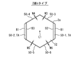
- FIGS. 10A to 10C are schematic bottom views of the key portion 5-2 of the key wrench 5.
- 10A to 10C the opening edge 3a of the hole is virtually shown by a broken line.
- the key portion 5-2 of the key wrench 5 includes the first side surface 50-1 to the sixth side surface 50-6.
- the first side surface 50-1 and the second side surface 50-2 are each a tapered surface TA.
- the taper angle of the first side surface 50-1 is preferably 1 degree or more, and the taper angle of the second side surface 50-2 is preferably 1 degree or more.
- the first side surface 50-1 and the second side surface 50-2 are surfaces adjacent to each other, in other words, surfaces connected to each other.
- each of the third side surface 50-3 to the sixth side surface 50-6 is a non-tapered surface.
- the taper angle of the third side surface 50-3 to the taper angle of the sixth side surface 50-6 is smaller than the taper angle of the first side surface 50-1, and smaller than the taper angle of the second side surface 50-2.
- the angle between the first side surface 50-1 and the side surface (fourth side surface 50-4) opposed to the first side surface is the sixth side surface 50-6, 6 larger than the angle between the side surface opposite to the side surface (third side surface 50-3).
- the angle between the second side surface 50-2 and the side surface facing the second side surface (fifth side surface 50-5) is the sixth side surface 50-6, and the side surface facing the sixth side surface It is larger than the angle between it and the third side surface 50-3).
- the first side surface 50-1 which is a first tapered surface and the second side surface 50 which is a second tapered surface. -2 contacts the open edge 3a of the hole.
- the side surface (fourth side surface 50-4) opposite to the first side surface 50-1 functions as a guide surface and comes in contact with the opening edge 3a of the hole.
- the side surface (fifth side surface 50-5) opposite to the second side surface 50-2 functions as a guide surface and comes in contact with the opening edge 3a of the hole.
- the third side surface 50-3 and the sixth side surface 50-6 do not contact the opening edge 3a.
- the gap W3 between the third side surface 50-3 and the opening edge 3a is about 0.001 inch (0.025 mm) at the height corresponding to the opening edge 3a of the hole.
- the gap W6 between the sixth side surface 50-6 and the opening edge 3a is about 0.001 inch (0.025 mm).
- the first side surface 50-1 and the second side surface 50-2 are the third side surface 50-3 to the sixth side surface in the cross section at the height corresponding to the opening edge 3a of the hole. It is located outward of a virtual regular hexagon defined by 50-6.
- the cross section (the cross section B1 or the cross section B2) perpendicular to the longitudinal axis of the key portion 5-2 has any of six sides forming a virtual regular hexagon.
- the items described in this paragraph also apply to the following second and third examples.
- the key portion 5-2 of the key wrench 5 includes the first side surface 50-1 to the sixth side surface 50-6.
- the first side surface 50-1 and the second side surface 50-2 are each a tapered surface TA.
- the taper angle of the first side surface 50-1 is preferably 1 degree or more, and the taper angle of the second side surface 50-2 is preferably 1 degree or more.
- the first side surface 50-1 and the second side surface 50-2 are connected to each other via the sixth side surface 50-6.
- the first side surface 50-1 and the second side surface 50-2 are separated from each other by the sixth side surface 50-6.
- each of the third side surface 50-3 to the sixth side surface 50-6 is a non-tapered surface.
- the taper angle of the third side surface 50-3 to the taper angle of the sixth side surface 50-6 is smaller than the taper angle of the first side surface 50-1, and smaller than the taper angle of the second side surface 50-2.
- the first side surface 50-1 which is a first tapered surface and the second side surface 50 which is a second tapered surface. -2 contacts the open edge 3a of the hole.
- the third side surface 50-3 which is the side surface facing the sixth side surface 50-6, functions as a guide surface and comes in contact with the opening edge 3a of the hole.
- the fourth side surface 50-4 to the sixth side surface 50-6 do not contact the opening edge 3a.
- the gap W4 between the fourth side surface 50-4 and the opening edge 3a is about 0.0005 inches (0.013 mm) at the height corresponding to the opening edge 3a of the hole.
- the gap W5 between the fifth side surface 50-5 and the opening edge 3a is about 0.0005 inch (0.013 mm), and the gap W5 between the sixth side surface 50-6 and the opening edge 3a is The gap W6 is about 0.002 inch (0.051 mm).
- the key portion 5-2 of the key wrench 5 includes the first side surface 50-1 to the sixth side surface 50-6.
- the first side surface 50-1 and the second side surface 50-2 are each a tapered surface TA.
- the taper angle of the first side surface 50-1 is preferably 1 degree or more, and the taper angle of the second side surface 50-2 is preferably 1 degree or more.
- the first side surface 50-1 and the second side surface 50-2 are surfaces facing each other. That is, the first side surface 50-1 and the second side surface 50-2 are not directly connected.
- each of the third side surface 50-3 to the sixth side surface 50-6 is a non-tapered surface.
- the taper angle of the third side surface 50-3 to the taper angle of the sixth side surface 50-6 is smaller than the taper angle of the first side surface 50-1, and smaller than the taper angle of the second side surface 50-2.
- the angle between the first side surface 50-1 and the side surface facing the first side surface (second side surface 50-2) is the sixth side surface 50-6, 6 larger than the angle between the side face opposite to the side face (the fourth side face 50-4).
- the gap W3 between the third side surface 50-3 and the opening edge 3a is about 0.001 inch (0.025 mm)
- the gap W4 between the fourth side surface 50-4 and the opening edge 3a is about 0.001 inch (0.025 mm)
- the gap W4 between the fifth side surface 50-5 and the opening edge 3a The gap W5 is about 0.001 inch (0.025 mm)
- the gap W6 between the sixth side surface 50-6 and the opening edge 3a is about 0.001 inch (0.025 mm).
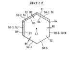
- FIGS. 10D to 10F are bottom views of the key portion 5-2 of the key wrench 5.
- 10D to 10F the opening edge 3a of the hole is virtually shown by a broken line.
- the key portion 5-2 of the key wrench 5 includes the first side surface 50-1 to the sixth side surface 50-6.
- the first side surface 50-1, the second side surface 50-2, and the third side surface 50-3 are each a tapered surface TA.
- the taper angle of the first side surface 50-1 is 1 degree or more
- the taper angle of the second side surface 50-2 is 1 degree or more
- the taper angle of the third side surface 50-3 is 1 degree or more Is preferred.
- the first side surface 50-1 and the second side surface 50-2 are surfaces adjacent to each other, in other words, surfaces connected to each other.
- the second side surface 50-2 and the third side surface 50-3 are surfaces adjacent to each other, in other words, surfaces connected to each other.
- each of the fourth side surface 50-4 to the sixth side surface 50-6 is a non-tapered surface.
- the taper angle of the fourth side surface 50-4 to the taper angle of the sixth side surface 50-6 is smaller than the taper angle of the first side surface 50-1, and smaller than the taper angle of the second side surface 50-2. Less than 50-3 taper angle.
- the first side surface 50-1 which is the first tapered surface and the third side surface 50 which is the third tapered surface. -3 contacts the open edge 3a of the hole.
- the fifth side surface 50-5 which is a side surface facing the second side surface 50-2, functions as a guide surface and comes in contact with the opening edge 3a of the hole.
- the fourth side surface 50-4 and the sixth side surface 50-6 do not contact the opening edge 3a.
- the gap W4 between the fourth side surface 50-4 and the opening edge 3a is about 0.0005 inches (0.013 mm)
- the gap W6 between the sixth side surface 50-6 and the opening edge 3a is about 0.0005 inch (0.013 mm).
- the second side surface 50-2 which is the second tapered surface, is not in contact with the opening edge 3a of the hole.
- the gap W2 between the second side surface 50-2 and the opening edge 3a is about 0.0005 inches (0.013 mm) It is.
- the first side surface 50-1 to the third side surface 50-3 are the fourth side surface 50-4 to the sixth side surface in the cross section at the height corresponding to the opening edge 3a of the hole. It is located outward of a virtual regular hexagon defined by 50-6.
- the cross section (the cross section B1 or the cross section B2) perpendicular to the longitudinal axis of the key portion 5-2 has any of six sides forming a virtual regular hexagon.
- Three overlapping sides see 50-4, 50-5, and 50-6 in FIG. 10D
- the items described in this paragraph also apply to the following fifth and sixth examples.
- the state of contact with the open edge 3a of each side in the example shown in FIG. 10D is the same as the state of contact with the open edge 3a of each side in the example shown in FIG. 10B. That is, in the example shown in FIG. 10D, the three side surfaces of the key portion contact the opening edge 3a. Therefore, the stress concentration at the surface 3 (the opening edge 3a) of the hole 2 is relaxed. As a result, deformation of the hole 2 is suppressed.
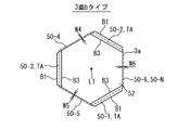
- the key portion 5-2 of the key wrench 5 includes the first side surface 50-1 to the sixth side surface 50-6.
- the first side surface 50-1, the second side surface 50-2, and the third side surface 50-3 are each a tapered surface TA.
- the taper angle of the first side surface 50-1 is 1 degree or more
- the taper angle of the second side surface 50-2 is 1 degree or more
- the taper angle of the third side surface 50-3 is 1 degree or more Is preferred.
- the first side surface 50-1 and the second side surface 50-2 are connected to each other via the sixth side surface 50-6. In other words, the first side surface 50-1 and the second side surface 50-2 are separated from each other by the sixth side surface 50-6.
- the second side surface 50-2 and the third side surface 50-3 are connected to each other via the fourth side surface 50-4. In other words, the second side surface 50-2 and the third side surface 50-3 are separated from each other by the fourth side surface 50-4.
- each of the fourth side surface 50-4 to the sixth side surface 50-6 is a non-tapered surface.
- the taper angle of the fourth side surface 50-4 to the taper angle of the sixth side surface 50-6 is smaller than the taper angle of the first side surface 50-1, and smaller than the taper angle of the second side surface 50-2. Less than 50-3 taper angle.
- the gap W4 between the fourth side surface 50-4 and the opening edge 3a is about 0.001 inch (0.025 mm)
- the gap W5 between the fifth side surface 50-5 and the opening edge 3a is about 0.001 inch (0.025 mm)
- the gap W5 between the sixth side surface 50-6 and the opening edge 3a is The gap W6 is about 0.001 inch (0.025 mm).
- the three side surfaces of the key portion contact the opening edge 3a. Therefore, the stress concentration at the surface 3 (the opening edge 3a) of the hole 2 is relaxed. As a result, deformation of the hole 2 is suppressed.
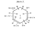
- the key portion 5-2 of the key wrench 5 includes the first side surface 50-1 to the sixth side surface 50-6.
- the first side surface 50-1, the second side surface 50-2, and the third side surface 50-3 are each a tapered surface TA.
- the taper angle of the first side surface 50-1 is 1 degree or more
- the taper angle of the second side surface 50-2 is 1 degree or more
- the taper angle of the third side surface 50-3 is 1 degree or more Is preferred.
- the first side surface 50-1 and the second side surface 50-2 are surfaces adjacent to each other, in other words, surfaces connected to each other.
- the third side surface 50-3 is a surface that faces the first side surface 50-1, and is a surface that is spaced apart from the first side surface 50-1 and the second side surface 50-2.
- each of the fourth side surface 50-4 to the sixth side surface 50-6 is a non-tapered surface.
- the taper angle of the fourth side surface 50-4 to the taper angle of the sixth side surface 50-6 is smaller than the taper angle of the first side surface 50-1, and smaller than the taper angle of the second side surface 50-2. Less than 50-3 taper angle.
- the gap W4 between the fourth side surface 50-4 and the opening edge 3a is about 0.001 inch (0.025 mm)
- the gap W5 between the fifth side surface 50-5 and the opening edge 3a is about 0.001 inch (0.025 mm)
- the gap W5 between the sixth side surface 50-6 and the opening edge 3a is The gap W6 is about 0.001 inch (0.025 mm).
- the three side surfaces contact the opening edge 3a. Therefore, the stress concentration at the surface 3 (the opening edge 3a) of the hole 2 is relaxed. As a result, deformation of the hole 2 is suppressed.
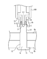
- FIG. 11 is a longitudinal sectional view showing an application example of a key wrench.
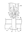
- FIG. 12 is a schematic perspective view showing an application example of a key wrench.
- illustration of a to-be-fastened member is abbreviate
- FIG. 11 describes how to fasten the to-be-fastened member 8 a and the to-be-fastened member 8 b using the bolt 1 a and the nut 1 b which are the fastening members 1.
- Each of the to-be-fastened member 8a and the to-be-fastened member 8b may be a plate member.
- the fastening member 1 (bolt 1a) includes a hole 2 into which the key portion 5-2 of the key wrench in the embodiment is inserted. The hole 2 is opened upward.
- the bolt 1 a includes a head 11 and a shaft 12.
- the surface 11 a on the shaft portion side of the head 11 is in contact with the to-be-fastened member 8 a.
- the shank 12 comprises a hole 2 at the center of the distal end.
- the end surface (distal surface) of the shaft portion 12 is provided with the hole 2.
- a first thread 13 is provided on the outer peripheral surface of the shaft 12.
- the nut 1 b comprises a second thread 14 which is screwed onto the first thread 13 of the bolt. Further, the outer peripheral surface 15 of the nut 1 b has a shape (for example, a shape having a polygonal cross section) which can be engaged with the tool 100.
- a method of fastening the to-be-fastened members 8a and 8b by the bolt 1a and the nut 1b will be described with reference to FIG.
- the bolt 1a is inserted into the holes of the fastened members 8a and 8b.
- the nut 1 b is temporarily attached to the bolt 1 a.
- the key portion 5-2 of the key wrench in the embodiment is inserted into the hole 2 provided in the shank of the bolt. By inserting the key portion 5-2 into the hole 2, the rotation of the bolt 1a about the central axis of the bolt is prevented.
- the tool 100 is engaged with the outer peripheral surface 15 of the nut 1 b.
- the tool 100 rotates (more specifically, the engagement portion of the nut 100 with the outer peripheral surface 15 of the tool 100 is rotated). ), The nut 1b is moved towards the head of the bolt 1a (screwed into the bolt 1a).
- the members to be fastened 8a and 8b are clamped by the head 11 of the bolt and the nut 1b. That is, the to-be-fastened members 8a and 8b are fastened by the bolt 1a and the nut 1b.
- the rotation of the tool 100 may be performed manually or may be performed using power.
- the key portion 5-2 of the key wrench in the embodiment includes the side surface (first side surface 50-1) that is a tapered surface, the occurrence of stress concentration on the surface 3 defining the hole 2 is suppressed.
- the key portion 5-2 includes a side surface (sixth side surface 50-6) that is a non-tapered surface. For this reason, the cam out load does not become excessive. As a result, it is possible to carry out the process of screwing the nut 1b into the bolt 1a more smoothly.
- the key wrench may be any of the key wrenches of the first to sixth examples described above.
- the size of the hole 2 provided in the shank 12 of the bolt is quite small. For this reason, a relatively large load acts on the key portion inserted into the hole 2 provided in the shaft portion 12 of the bolt. As a result, the stress concentration generated at the surface 3 defining the hole 2 tends to be large.
- the cam out load tends to be large.
- the key wrench a key wrench having a first side surface which is a tapered surface and a sixth side surface which is a non-tapered surface
- the problem of stress concentration and the problem of cam out load are summarized. Is solved. In other words, in the key wrench according to the embodiment, the effect of alleviating stress concentration and the effect of suppressing the cam out load are exhibited synergistically.
- FIG. 14 shows an analysis result of calculation of the torque at which the hole is broken when all six side surfaces of the key portion 5-2 are tapered and the taper angles of all the side surfaces are equal to each other. That is, FIG. 14 shows the analysis result for the key wrench in the comparative example.
- the side taper angle ⁇ was 2 degrees
- hole 2 was broken at about 45 in-lb (5.1 N ⁇ m). The fact that the hole is broken means that the torque holding ability of the hole is substantially lost.
- the side taper angle was 3 degrees
- the hole 2 was broken at about 40 in-lb (4.5 N ⁇ m).
- the side taper angle is 4 degrees
- the hole 2 is broken at about 35 in-lb (4.0 N ⁇ m).
- FIG. 15 relates to the shapes of the six sides of the key portion 5-2: (1) if all sides are non-tapered, (2) if all sides are tapered, (3) one side (4) Analysis where the cam out load Fz of the key portion 5-2 is calculated when only the two side surfaces are tapered surfaces, and (5) the case where only the three side surfaces are tapered surfaces. Show the results.
- the cam-out load Fz means an upward load received by the key portion 5-2, as shown in FIG.
- the six side surfaces of the key portion 5-2 include only one, only two, or only three tapered surfaces, as compared with the case where all the six side surfaces are tapered surfaces. It is possible to effectively suppress the come-out.
- the shape of the key portion 5-2 is (1) a shape corresponding to the above-described first example, (2) a case corresponding to the above-described second example, (3) the above-described In the case of the shape corresponding to the third example, (4) in the case of the shape corresponding to the above-mentioned fourth example, (5) in the case of the shape corresponding to the above-mentioned fifth example, (6) the above-mentioned sixth example
- (C) the key portion 5-2 begins to cam out
- the analysis result which calculated torque is shown.
- the torque which starts to come out means the torque at which the key portion 5-2 starts to cam out when the key portion 5-2 is held down with a load of 10 kgf.
- the cam out is effectively suppressed even when a relatively large torque acts on key portion 5-2.
- the taper angle may be reduced.
- the taper angle is, for example, 2.5 ° or less, 2.0 ° or less, or 1.5 ° or less from the viewpoint of suppressing the cam out.
- the taper angle is less than 1.0 °, the risk of the free end of the key portion 5-2 coming into contact with the bottom of the hole 2 increases.
- the tapered surface can not properly contact the opening edge 3a of the hole.
- the taper angle is preferably 1.0 ° or more.
- the key wrench in the first to sixth examples is superior to the key wrench in the comparative example shown in FIG.
- the first example, the second example, and the fourth example are particularly excellent.
- the taper angle may be reduced in order to increase the torque at which the hole is broken.
- the torque at which the hole is broken is 50 in-lb (about 5.5 N ⁇ m More than).
- the torque at which the hole is broken exceeds 60 in-lb (about 6.6 N ⁇ m).
- the two tapered surfaces are adjacent to each other (first example).
- the number of tapered surfaces is three
- three tapered surfaces are continuous (in other words, the first side surface 50-1 which is a tapered surface and the tapered surface)
- the second side surface 50-2 and the second side surface 50-2 are adjacent to each other, and the second side surface 50-2 as the tapered surface and the third side surface 50-3 as the tapered surface are adjacent to each other).
- the taper angle is preferably 1 ° or more and 2.5 ° or less, and particularly preferably 1 ° or more and 2 ° or less.
- FIG. 17 relates to the six sides of the key portion 5-2: (1) if all sides are non-tapered, (2) if only one side is tapered, (3) only two sides
- the following shows the experimental results of measuring the average value of the torque at which the hole 2 breaks for each of the cases where (4) only three side surfaces are tapered surfaces when (1) is a tapered surface.
- the number of tapered surfaces is most preferably two, and next, the number of tapered surfaces is preferably three.
- FIG. 18 shows that (1) when the shape of the key portion 5-2 is a shape corresponding to the above-described first example and the taper angle is 1.5 °, (2) of the key portion 5-2
- the experimental result which measured the torque which the hole 2 breaks is shown about each in the case where a shape is a shape corresponding to the above-mentioned 1st example, and a taper angle is 2.0 degrees.
- a shape is a shape corresponding to the above-mentioned 1st example, and a taper angle is 2.0 degrees.
- the number of tapered surfaces is preferably two or three, more preferably two, rather than one.
- the taper angle of the tapered surface is preferably 1 ° or more and 2.5 ° or less, and particularly preferably 1 ° or more and 2 ° or less, or 1.5 ° or more and 2 ° or less.
- the plurality of tapered surfaces are disposed adjacent to each other (for example, the first side surface which is a tapered surface and the second side surface which is a tapered surface are adjacent to each other) Is preferable.
Landscapes
- Engineering & Computer Science (AREA)
- Mechanical Engineering (AREA)
- Details Of Spanners, Wrenches, And Screw Drivers And Accessories (AREA)
- Connection Of Plates (AREA)
Abstract
Description
本明細書では、キーレンチのキー部分の遠位端(自由端)から近位方向に向かう方向を「第1方向」と定義する。本明細書において、「上方」は、第1方向に対応する。すなわち、本明細書においては、現実には、第1方向と鉛直上向きの方向とが一致しない場合であっても、「第1方向」が上方であると定義される。また、本明細書において、「下方(第2方向)」は、「上方(第1方向)」とは反対の方向を意味する。
(1)キーレンチのキー部分の長手方向に垂直な断面のうちの少なくとも1つの断面が正多角形である場合、キー部分の長手方向中心軸L1は、当該正多角形の断面に垂直で当該正多角形の断面の中心をとおる軸を意味する。
(2)キーレンチのキー部分の長手方向に垂直な断面のすべてが正多角形でない場合には、キー部分の長手方向に垂直な1つの断面と、キー部分の側面のうち非テーパー面である側面との交線を、非テーパー面に対応する辺と定義する。キー部分の長手方向中心軸L1は、当該非テーパー面に対応する辺の全てからの距離が等しい点をとおり、当該1つの断面に垂直な軸を意味する。(図3を参照。各非テーパー面に対応する辺と、長手方向中心軸L1との距離はDである。)
(3)上記「(1)」および「(2)」を考慮しても、キーレンチのキー部分の長手方向中心軸L1がどの仮想直線に対応するのかが不明である時には、キー部分の長手方向中心軸L1は、キーレンチのキー部分の端面(自由端面)の面積中心をとおり、端面に垂直な軸を意味する。なお、端面が丸みを有する場合は、丸み部分を除いた部分を端面と定義する。(図4を参照)
図5を参照して、テーパー面TAを有するキーレンチ5’が締結部材1の穴2に挿入された状態において、キーレンチ5’と締結部材1との間で回転トルクが伝達される場合を想定する。この場合、当該回転トルクに起因して、キーレンチ5’には、内向きの力Fが作用する(必要であれば、図1に示された内向きの力Fも参照)。本明細書において、当該内向きの力のうちの上向き成分(Fz)を、「カムアウト荷重」と呼ぶ。当該カムアウト荷重が大きい場合、キーレンチを保持する作業者あるいは機械にとっての負担が大きくなる。特に、穴2のサイズ(断面積)が小さい場合、あるいは、キーレンチ5’と締結部材1との間で伝達される回転トルクの大きさが大きい場合には、カムアウト荷重の問題は顕著となる。
図6乃至図8を参照して、実施形態におけるキーレンチ5について説明する。図6は、実施形態におけるキーレンチ5の概略斜視図である。図7は、キーレンチ5のキー部分5-2を穴2に挿入した状態を示す縦断面図である。図8は、図6における面Aでのキーレンチ5の断面図(キーレンチの長手方向中心軸L1に垂直な断面における断面図)である。
図10A乃至図10Cを参照して、テーパー面が2個ある場合の実施形態について説明する。図10A乃至図10Cは、キーレンチ5のキー部分5-2の概略底面図である。なお、図10A乃至図10Cにおいて、穴の開口端縁3aが破線によって仮想的に示されている。
図10Aに記載の第1例では、キーレンチ5のキー部分5-2は、第1側面50-1乃至第6側面50-6を備える。第1側面50-1および第2側面50-2は、それぞれ、テーパー面TAである。第1側面50-1のテーパー角度は、1度以上であり、第2側面50-2のテーパー角度は、1度以上であることが好ましい。
図10Bに記載の第2例では、キーレンチ5のキー部分5-2は、第1側面50-1乃至第6側面50-6を備える。第1側面50-1および第2側面50-2は、それぞれ、テーパー面TAである。第1側面50-1のテーパー角度は、1度以上であり、第2側面50-2のテーパー角度は、1度以上であることが好ましい。
図10Cに記載の第3例では、キーレンチ5のキー部分5-2は、第1側面50-1乃至第6側面50-6を備える。第1側面50-1および第2側面50-2は、それぞれ、テーパー面TAである。第1側面50-1のテーパー角度は、1度以上であり、第2側面50-2のテーパー角度は、1度以上であることが好ましい。
図10D乃至図10Fを参照して、テーパー面が2個ある場合の実施形態について説明する。図10D乃至図10Fは、キーレンチ5のキー部分5-2の底面図である。なお、図10D乃至図10Fにおいて、穴の開口端縁3aが破線によって仮想的に示されている。
図10Dに記載の第4例では、キーレンチ5のキー部分5-2は、第1側面50-1乃至第6側面50-6を備える。第1側面50-1、第2側面50-2、および、第3側面50-3は、それぞれ、テーパー面TAである。第1側面50-1のテーパー角度は、1度以上であり、第2側面50-2のテーパー角度は、1度以上であり、第3側面50-3のテーパー角度は、1度以上であることが好ましい。
図10Eに記載の第5例では、キーレンチ5のキー部分5-2は、第1側面50-1乃至第6側面50-6を備える。第1側面50-1、第2側面50-2、および、第3側面50-3は、それぞれ、テーパー面TAである。第1側面50-1のテーパー角度は、1度以上であり、第2側面50-2のテーパー角度は、1度以上であり、第3側面50-3のテーパー角度は、1度以上であることが好ましい。
図10Fに記載の第6例では、キーレンチ5のキー部分5-2は、第1側面50-1乃至第6側面50-6を備える。第1側面50-1、第2側面50-2、および、第3側面50-3は、それぞれ、テーパー面TAである。第1側面50-1のテーパー角度は、1度以上であり、第2側面50-2のテーパー角度は、1度以上であり、第3側面50-3のテーパー角度は、1度以上であることが好ましい。
図11および図12を参照して、キーレンチの適用例について説明する。図11は、キーレンチの適用例を示す縦断面図である。図12は、キーレンチの適用例を示す概略斜視図である。なお、図12において、被締結部材の図示は、省略されている。
実験は、図13に記載の装置を用いて行った。なお、穴2の対向側面間の距離D1は、3/32インチ(約2.38mm)であった。また、ナット1bをR方向に回転させて、ナット1bをボルト1aにねじ込む際に、キー部分5-2に作用するトルクが測定された。
Claims (7)
- Nを3以上の任意の自然数と定義する時、N角形状の穴に係合可能なキー部分と、
基端部分と
を具備し、
前記キー部分は、第1側面、第2側面、および、第N側面を含むN個の側面を備え、
前記第1側面は、テーパー面であり、
前記第N側面は、非テーパー面である
キーレンチ。 - 前記キー部分は、第3側面を含み、
前記第2側面および第3側面のうちの少なくとも1つは、テーパー面であり、
前記N個の側面のうち、前記第1側面、前記第2側面、および、前記第3側面以外の側面は、非テーパー面である
請求項1に記載のキーレンチ。 - 前記第2側面は、テーパー面であり、
前記第3側面は、非テーパー面である
請求項2に記載のキーレンチ。 - 前記第2側面は、テーパー面であり、
テーパー面である前記第1側面と、テーパー面である前記第2側面とは、互いに隣接している
請求項2または3に記載のキーレンチ。 - 前記第1側面のテーパー角度は、1°以上2.5°以下である
請求項1乃至4のいずれか一項に記載のキーレンチ。 - 前記キー部分の長手方向軸に垂直な断面は、仮想的な正N角形を構成するN個の辺のいずれかに重なる2つ以上の辺と、前記仮想的な正N角形の外方に位置する少なくとも1つの辺を含む
請求項1乃至5のいずれか一項に記載のキーレンチ。 - Nを3以上の任意の自然数と定義する時、N角形状の穴に係合可能なキー部分と、
基端部分と
を具備し、
前記キー部分は、第1側面、第2側面、および、第N側面を含むN個の側面を備え、
前記第1側面は、前記キー部分の長手方向中心軸である第1軸に対して傾斜した第1テーパー面を含み、
前記第N側面と前記第1軸との間のなす角度である第Nテーパー角度は、前記第1側面と前記第1軸との間のなす角度である第1テーパー角度よりも小さい
キーレンチ。
Priority Applications (4)
| Application Number | Priority Date | Filing Date | Title |
|---|---|---|---|
| CA3014276A CA3014276C (en) | 2016-04-21 | 2017-01-06 | Key wrench |
| CN201780010491.XA CN108698213A (zh) | 2016-04-21 | 2017-01-06 | 内角扳手 |
| EP17785582.2A EP3412413A4 (en) | 2016-04-21 | 2017-01-06 | CLEF ALLEN |
| US16/075,412 US20190039216A1 (en) | 2016-04-21 | 2017-01-06 | Key wrench |
Applications Claiming Priority (2)
| Application Number | Priority Date | Filing Date | Title |
|---|---|---|---|
| JP2016-085373 | 2016-04-21 | ||
| JP2016085373A JP2017193022A (ja) | 2016-04-21 | 2016-04-21 | キーレンチ |
Publications (1)
| Publication Number | Publication Date |
|---|---|
| WO2017183237A1 true WO2017183237A1 (ja) | 2017-10-26 |
Family
ID=60115983
Family Applications (1)
| Application Number | Title | Priority Date | Filing Date |
|---|---|---|---|
| PCT/JP2017/000282 WO2017183237A1 (ja) | 2016-04-21 | 2017-01-06 | キーレンチ |
Country Status (6)
| Country | Link |
|---|---|
| US (1) | US20190039216A1 (ja) |
| EP (1) | EP3412413A4 (ja) |
| JP (1) | JP2017193022A (ja) |
| CN (1) | CN108698213A (ja) |
| CA (1) | CA3014276C (ja) |
| WO (1) | WO2017183237A1 (ja) |
Families Citing this family (2)
| Publication number | Priority date | Publication date | Assignee | Title |
|---|---|---|---|---|
| CN110420063B (zh) * | 2019-08-18 | 2024-09-20 | 桂林市锐锋医疗器械有限公司 | 一种堵头结构及含其的手柄 |
| TWI826200B (zh) * | 2022-12-22 | 2023-12-11 | 劉冠廷 | 六角扳手結構 |
Citations (5)
| Publication number | Priority date | Publication date | Assignee | Title |
|---|---|---|---|---|
| US3894450A (en) * | 1971-03-25 | 1975-07-15 | Tore L Hill | Combined screw driving and screw gripping tool |
| JP2000052264A (ja) | 1998-08-12 | 2000-02-22 | Asahi Seimitsu Kk | レンチ |
| DE10107751A1 (de) * | 2001-02-16 | 2002-08-22 | Werner Hermann Wera Werke | Schraubwerkzeug |
| JP2012518447A (ja) * | 2009-02-23 | 2012-08-16 | ビオテック アーンテルナシオナール(ソシエテ パー アクションズ サンプリフェ) | 五角形凹部を有したネジ、特に整形外科用のネジを回すための五角ドライバー |
| JP2016085373A (ja) | 2014-10-27 | 2016-05-19 | オリンパス株式会社 | 撮像素子付中間筒 |
Family Cites Families (7)
| Publication number | Priority date | Publication date | Assignee | Title |
|---|---|---|---|---|
| US4503737A (en) * | 1983-04-11 | 1985-03-12 | Digiovanni Donald | Threaded fastener removing tool |
| DE9001707U1 (de) * | 1990-02-14 | 1991-06-13 | Wera-Werk Hermann Werner Gmbh & Co, 5600 Wuppertal | Innenbuchsensechskantschlüssel |
| DE9110904U1 (de) * | 1991-05-02 | 1992-09-03 | Wera-Werk Hermann Werner Gmbh & Co, 5600 Wuppertal | Schraubwerkzeug, insbesondere Schraubendreher |
| JP4307583B2 (ja) * | 1997-12-10 | 2009-08-05 | 勝行 戸津 | ねじ及びドライバービットまたはレンチとの組合せ |
| US20050166724A1 (en) * | 2004-01-29 | 2005-08-04 | Hand Innovations, Inc. | Twisted and tapered driver for a threaded fastener |
| CN201519930U (zh) * | 2009-09-25 | 2010-07-07 | 徐尚仁 | 可进退防盗螺丝专用的内套外吻合式扳手套筒 |
| KR101451521B1 (ko) * | 2013-09-10 | 2014-10-23 | (주)티디엠 | 육각 드라이버 팁 |
-
2016
- 2016-04-21 JP JP2016085373A patent/JP2017193022A/ja active Pending
-
2017
- 2017-01-06 WO PCT/JP2017/000282 patent/WO2017183237A1/ja active Application Filing
- 2017-01-06 CA CA3014276A patent/CA3014276C/en not_active Expired - Fee Related
- 2017-01-06 US US16/075,412 patent/US20190039216A1/en not_active Abandoned
- 2017-01-06 EP EP17785582.2A patent/EP3412413A4/en not_active Withdrawn
- 2017-01-06 CN CN201780010491.XA patent/CN108698213A/zh active Pending
Patent Citations (5)
| Publication number | Priority date | Publication date | Assignee | Title |
|---|---|---|---|---|
| US3894450A (en) * | 1971-03-25 | 1975-07-15 | Tore L Hill | Combined screw driving and screw gripping tool |
| JP2000052264A (ja) | 1998-08-12 | 2000-02-22 | Asahi Seimitsu Kk | レンチ |
| DE10107751A1 (de) * | 2001-02-16 | 2002-08-22 | Werner Hermann Wera Werke | Schraubwerkzeug |
| JP2012518447A (ja) * | 2009-02-23 | 2012-08-16 | ビオテック アーンテルナシオナール(ソシエテ パー アクションズ サンプリフェ) | 五角形凹部を有したネジ、特に整形外科用のネジを回すための五角ドライバー |
| JP2016085373A (ja) | 2014-10-27 | 2016-05-19 | オリンパス株式会社 | 撮像素子付中間筒 |
Non-Patent Citations (1)
| Title |
|---|
| See also references of EP3412413A4 |
Also Published As
| Publication number | Publication date |
|---|---|
| CA3014276C (en) | 2020-11-10 |
| CA3014276A1 (en) | 2017-10-26 |
| EP3412413A1 (en) | 2018-12-12 |
| CN108698213A (zh) | 2018-10-23 |
| EP3412413A4 (en) | 2019-04-17 |
| US20190039216A1 (en) | 2019-02-07 |
| JP2017193022A (ja) | 2017-10-26 |
Similar Documents
| Publication | Publication Date | Title |
|---|---|---|
| AU2017245465B2 (en) | Socket drive improvement | |
| JP5655208B2 (ja) | 焼付き防止ボルト | |
| KR20100039363A (ko) | 억지 끼워맞춤을 수반한 소엽식 드라이브 시스템과 그 제조방법 및 제조장치 | |
| US11806843B2 (en) | Socket drive improvement | |
| CA3124034C (en) | Socket drive improvement | |
| WO2017183237A1 (ja) | キーレンチ | |
| JP2009115297A (ja) | 緩み止めナット、その製造方法、及びその加工用治具 | |
| JP2007187215A (ja) | ボルト、ナットの緩み止め部材、安全ボルトナット装置及び取り付け方法 | |
| JP7116899B1 (ja) | 緩み防止機能を有するコンビネーションナット | |
| JP2018185043A (ja) | 三点留め具 | |
| JP3218084U (ja) | ねじ部材 | |
| JP2016221669A (ja) | 六角レンチの構造 | |
| JP4418025B1 (ja) | ボルトナット締結体 | |
| JP3532180B2 (ja) | シャートルクナット | |
| JP6931470B2 (ja) | ボルト及びそれを用いた締結部材並びにそれを用いた締結方法 | |
| JP2002039142A (ja) | 緩み止め座金 | |
| JP2023516455A (ja) | ねじ | |
| JP2006010054A (ja) | ユルミ止めナット |
Legal Events
| Date | Code | Title | Description |
|---|---|---|---|
| WWE | Wipo information: entry into national phase |
Ref document number: 2017785582 Country of ref document: EP |
|
| WWE | Wipo information: entry into national phase |
Ref document number: 3014276 Country of ref document: CA |
|
| ENP | Entry into the national phase |
Ref document number: 2017785582 Country of ref document: EP Effective date: 20180806 |
|
| NENP | Non-entry into the national phase |
Ref country code: DE |
|
| 121 | Ep: the epo has been informed by wipo that ep was designated in this application |
Ref document number: 17785582 Country of ref document: EP Kind code of ref document: A1 |