WO2017179731A1 - 口腔機能のトレーニング用器具 - Google Patents
口腔機能のトレーニング用器具 Download PDFInfo
- Publication number
- WO2017179731A1 WO2017179731A1 PCT/JP2017/015395 JP2017015395W WO2017179731A1 WO 2017179731 A1 WO2017179731 A1 WO 2017179731A1 JP 2017015395 W JP2017015395 W JP 2017015395W WO 2017179731 A1 WO2017179731 A1 WO 2017179731A1
- Authority
- WO
- WIPO (PCT)
- Prior art keywords
- pressure
- oral
- pressure receiving
- oral cavity
- fluid
- Prior art date
- Legal status (The legal status is an assumption and is not a legal conclusion. Google has not performed a legal analysis and makes no representation as to the accuracy of the status listed.)
- Ceased
Links
Images


Classifications
-
- A—HUMAN NECESSITIES
- A63—SPORTS; GAMES; AMUSEMENTS
- A63B—APPARATUS FOR PHYSICAL TRAINING, GYMNASTICS, SWIMMING, CLIMBING, OR FENCING; BALL GAMES; TRAINING EQUIPMENT
- A63B23/00—Exercising apparatus specially adapted for particular parts of the body
- A63B23/025—Exercising apparatus specially adapted for particular parts of the body for the head or the neck
- A63B23/03—Exercising apparatus specially adapted for particular parts of the body for the head or the neck for face muscles
Definitions
- the present invention relates to a training device used for training oral-related muscles such as tongue and facial muscles, and for confirming the effects of swallowing rehabilitation, and the like. It belongs to the technical field of a structure for confirming etc. outside the oral cavity.
- the training device of Patent Document 1 includes a base portion that is inserted into the oral cavity, and a hollow bulge portion that is formed of an elastic body so as to bulge from the base portion. A step is provided. Then, after the base is inserted into the user's mouth, when the user pushes the bulging part with the tongue, the step of the bulging part is elastically deformed when the force by the tongue becomes greater than a predetermined value. The bulging part suddenly elastically deforms as a trigger for the start. The bulging portion vibrates at the moment when the sudden elastic deformation occurs, and this vibration is transmitted to the tongue and the hard palate, thereby causing the user to feel the vibration. In other words, when training, the user needs to put power on the tongue until vibration occurs, so you can clearly see how much force you can apply during training to get the training effect, Can be effectively performed.
- the confirmation method includes a confirmation method using a tongue pressure measuring instrument used in medical institutions and the like, and a confirmation method using the instrument disclosed in Patent Document 1.
- the tongue pressure can be confirmed numerically, so it has the advantage of being able to grasp it as an accurate value, but it is expensive because it incorporates a high-precision sensor, etc. There was a problem that it was difficult to spread in general.
- the present invention has been made in view of the above points, and the purpose of the present invention is to enable the oral function training to be obtained outside the oral cavity and to provide oral function training.
- An effect is to be able to confirm the effect inexpensively and reliably outside the oral cavity.
- the effect of training of oral function can be confirmed using hand sensation.
- the first invention is A pressure receiving portion that is made of an elastic material having a fluid filling portion that is filled with fluid inside, and that is inserted into the oral cavity and elastically deforms by receiving external force in the oral cavity, A pressure transmission part having a contact part disposed outside the oral cavity and touched by a hand, and made of an elastic material having a fluid filling part filled with fluid inside, It is characterized by comprising a tubular member communicating with the fluid filling part of the pressure receiving part and the fluid filling part of the pressure transmission part and filled with fluid inside.
- the pressure receiving portion when the user inserts the pressure receiving portion into the oral cavity and applies an external force to the pressure receiving portion by the force of the tongue, for example, the pressure receiving portion is elastically deformed and crushed, so the volume of the fluid filling portion of the pressure receiving portion Becomes smaller.
- the volume of the fluid filling portion of the pressure receiving portion changes, the fluid in the fluid filling portion flows into the tubular member and flows through the tubular member toward the pressure transmitting portion.
- the pressure transmission part is elastically deformed in the direction in which the volume of the fluid filling part of the pressure transmission part is enlarged.
- the hand touches the contact part of the pressure transmission part, and the hand is a sensitive part that can sense minute changes in shape, so that the elastic deformation of the pressure transmission part described above can be felt by hand. Will be able to.
- the pressure-transmitting portion has a large deformation amount.
- the user's oral-related function level is low and the pressure-receiving portion has a deformation amount. If is small, the amount of deformation of the pressure transmission part is small, so that the level of the oral cavity related function level is shown in an easy-to-understand form as the deformation amount of the pressure transmission part.
- the contact portion of the pressure transmission portion is provided with a mark portion serving as a mark.
- This configuration makes it possible to easily and accurately grasp the contact portion of the pressure transmission portion, so that the portion touched by the hand does not vary from person to person. This makes it possible to accurately confirm the effects of the swallowing function level and swallowing rehabilitation.
- the said mark part is a recessed part or a convex part provided in the surface of the said pressure transmission part, It is characterized by the above-mentioned.
- the position of the contact portion can be easily determined, and the position of the finger can be easily determined by bringing the finger into contact with the concave portion or the convex portion, for example.
- the said mark part is formed in the surface of the said pressure transmission part, It is a ring shape into which a finger
- the position of the finger is easily determined by inserting the finger into the mark portion.
- the tubular member is provided with an adjustment valve for adjusting the internal pressure of the pressure receiving part and the pressure transmission part.
- the internal pressures of the pressure receiving unit and the pressure transmission unit are increased by injecting fluid from the adjustment valve, and the internal pressures of the pressure reception unit and the pressure transmission unit are decreased by discharging the fluid from the adjustment valve. Therefore, the internal pressures of the pressure receiving part and the pressure transmission part are arbitrarily changed according to the amount of fluid injected and discharged. Thereby, for example, the internal pressures of the pressure receiving part and the pressure transmission part are increased so as to suit a user having a high tongue pressure, or the internal pressures of the pressure receiving part and the pressure transmission part are reduced so as to suit a user having a low tongue pressure. It becomes possible.
- the pressure receiving part and the pressure transmission part are constituted by a balloon.
- the pressure receiving unit and the pressure transmission unit have a simple configuration and are easily elastically deformed.
- the pressure receiving portion that is elastically deformed by receiving an external force in the oral cavity and the pressure transmitting portion that is disposed outside the oral cavity and has a contact portion that is touched by the hand are connected by the tubular member.
- the actual feeling that training is performed can be obtained outside the oral cavity, and the effect of training of oral function can be confirmed inexpensively and reliably outside the oral cavity.
- the contact portion can be easily and accurately grasped. Therefore, since the part touched with a hand does not vary with people, the swallowing function level and the effect of swallowing rehabilitation can be confirmed accurately.
- the concave portion or the convex portion formed on the surface of the pressure transmission portion is used as the mark portion, it is possible to easily determine the position of the contact portion, and for example, the finger contacts the concave portion or the convex portion. By doing so, it becomes easy to determine the position of the finger, and it is possible to suppress the portion touched by the hand from being scattered by a person.
- the finger since the finger can be inserted into the mark portion, the position of the finger can be easily determined, and the portion touched by the hand can be prevented from being dispersed by a person.
- the internal pressure of the pressure receiving part and the pressure transmission part can be adjusted so as to match the user's oral-related function level, so that the swallowing function level and the effects of swallowing rehabilitation are further improved. It can be confirmed more accurately.
- the pressure receiving unit and the pressure transmission unit can be easily configured to be elastically deformed while reducing costs, and the effect of the swallowing function level and swallowing rehabilitation can be accurately determined. Can be confirmed.
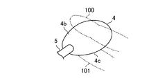
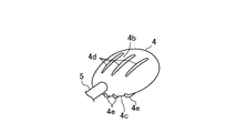
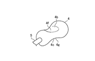
- FIG. 1 It is a figure which shows schematic structure of the instrument for oral function training which concerns on embodiment. It is a perspective view of a pressure transmission part. It is a perspective view of the pressure transmission part which concerns on the modification 1 of embodiment. It is a perspective view of the pressure transmission part which concerns on the modification 2 of embodiment. It is a perspective view of the pressure transmission part which concerns on the modification 3 of embodiment.
- the “vertical direction” is a direction in which the pressure receiving portion 2 is crushed by the user's tongue and hard palate when the pressure receiving portion 2 of the training device 1 for oral function is inserted into the oral cavity.
- the “left-right direction” corresponds to the left-right direction of the user when the pressure receiving portion 2 of the training device 1 is inserted into the oral cavity.
- FIG. 1 shows an oral function training device 1 according to Embodiment 1 of the present invention.
- the training device 1 can perform training to train oral muscles and facial muscles, and can confirm the effects of the swallowing function level and swallowing rehabilitation.
- the training for training the muscles related to the oral cavity and the muscles of the face is a training mainly aimed at improving the muscular strength of the lips and the tongue, and the sophistication of their movements. It is also possible to train for the purpose of improving the muscle strength of the cheeks.
- the muscle strength of the tongue is greatly involved in the swallowing function, the level of the swallowing function can be confirmed by checking the muscle strength of the tongue.
- swallowing rehabilitation is a rehabilitation mainly aimed at improving tongue muscle strength, oral muscles, and facial muscles. By confirming tongue muscle strength, oral muscles, and facial muscles, The effect of swallowing rehabilitation can be confirmed.
- the training device 1 can be used for a person who has a particularly weak tongue and a person who has a particularly poor operation.
- those who are paralyzed in the oral cavity can also use the training device 1.
- the training instrument 1 includes a pressure receiving portion 2, a gripping portion 3, a pressure transmission portion 4, a tubular member 5, and an adjustment valve 6.
- the pressure receiving part 2 can be comprised, for example with a balloon.
- the pressure receiving portion 2 is made of an elastic material having a hollow fluid filling portion 2a filled with a fluid therein, and is inserted into a user's oral cavity and receives an external force in the oral cavity to be elastically deformed. Is configured to do.
- the pressure receiving portion 2 is formed so as not to pass fluid.
- the elastic material constituting the pressure receiving portion 2 examples include at least one selected from the group consisting of silicone rubber, polypropylene, polyethylene, polyvinyl chloride, thermoplastic elastomer, natural rubber and the like, or a material obtained by mixing any plurality.
- silicone rubber polypropylene
- polyethylene polyethylene
- polyvinyl chloride polyvinyl chloride
- thermoplastic elastomer natural rubber and the like
- a material obtained by mixing any plurality a material obtained by mixing any plurality.
- various elastic materials having a hardness range that can be elastically deformed when a force (external force) by the tongue is applied can be used.
- a preferable hardness range is 30 to 60 in Shore A (using a durometer).
- the size of the pressure receiving portion 2 is set to such an extent that the entire pressure receiving portion 2 can be inserted into the user's oral cavity, and can be changed according to the user's physique, age, and gender.
- the pressure receiving portion 2 may have a spherical shape, but a flat shape is preferable. By adopting a flat shape, the pressure receiving part 2 can be stabilized, for example, on the tongue in a state where the pressure receiving part 2 is inserted into the oral cavity. Moreover, the pressure receiving part 2 is set so that the dimension in the insertion direction into the oral cavity is longer than the dimension in the left-right direction.
- the grip portion 3 is made of a material harder than the elastic material constituting the pressure receiving portion 2 and is formed in a cylindrical shape.
- a passage 3 a is formed inside the grip portion 3.
- the passage 3 a extends over both ends in the longitudinal direction of the grip portion 3.
- the grip portion 3 is fixed to one end portion in the longitudinal direction of the pressure receiving portion 2, and one end portion of the passage 3 a of the grip portion 3 and the fluid filling portion 2 a of the pressure receiving portion 2 are connected in a fixed state to the pressure receiving portion 2.
- the dimension of the grip part 3 in the center line direction is set to be sufficiently longer than the dimension of the pressure receiving part 2 in the longitudinal direction.
- the gripping part 3 has such a rigidity that it does not deform when held by hand or chewed by the front teeth.
- connection portion 3b On the side opposite to the connection side to the pressure receiving portion 2 in the grip portion 3, a cylindrical connection portion 3b is provided.
- the passage 3a is formed inside the connection portion 3b, and the passage 3a opens at the end of the connection portion 3b.
- One end portion of the tubular member 5 is connected to the connecting portion 3b, whereby the tubular member 5 and the fluid filling portion 2a of the pressure receiving portion 2 communicate with each other.
- the pressure transmission part 4 can be constituted by a balloon or the like made of the same material as that constituting the pressure receiving part 2.
- the pressure transmission part 4 is a part which consists of an elastic material which has the hollow fluid filling part 4a with which the inside is filled with a fluid, and is arrange
- the pressure transmission part 4 may be spherical, a flat shape is preferable. By adopting a flat shape, a curved surface having a large curvature and a curved surface having a small curvature can be formed on the outer surface of the pressure transmitting portion 4, and the pressure transmitting portion 4 is provided so that the hand touches the curved surface having a large curvature.
- the pressure transmission unit 4 can be stabilized.
- a shape of the pressure transmission part 4 it can be set as arbitrary shapes, such as an elongate rod shape, plate shape, pyramid shape, cone shape, for example.
- the pressure transmission part 4 since the pressure transmission part 4 has a flat shape, curved surfaces having large curvatures are formed on the outer surface of the pressure transmission part 4 on both sides in the thickness direction of the pressure transmission part 4, respectively. And in this embodiment, the curved surface with a large curvature in the outer surface of the pressure transmission part 4 becomes the 1st contact surface (contact part) 4b and 2nd contact surface (contact part) 4c which a user's hand touches, respectively. ing. Therefore, the first contact surface 4 b and the second contact surface 4 c are formed on both sides in the thickness direction of the pressure transmission unit 4.
- the tubular member 5 can be made of a flexible resin tube or the like.
- the other end portion of the tubular member 5 is connected to one end portion in the longitudinal direction of the pressure transmission portion 4, and the tubular member 5 and the fluid filling portion 4 a of the pressure transmission portion 4 communicate with each other.
- the material constituting the tubular member 5 is a material that is more difficult to deform than the pressure receiving portion 2 and the pressure transmitting portion 4, and the diameter of the tubular member 5 hardly changes when the pressure receiving portion 2 is crushed and the internal pressure rises. I am doing so.
- the length of the tubular member 5 can be set, for example, between several tens of cm to 100 cm. However, the length is not limited to this range, and the pressure transmitting unit 4 is inserted with the pressure receiving unit 2 inserted into the oral cavity. It may be long enough to be held by hand.
- the tubular member 5 is also filled with fluid.
- the adjustment valve 6 is for adjusting the internal pressure of the pressure receiving part 2 and the pressure transmission part 4, that is, the internal pressure of the fluid filling part 2a and the fluid filling part 4a.
- the regulating valve 6 can be constituted by, for example, a well-known check valve used in a medical field, and a syringe (not shown) or the like is connected to the regulating valve 6 so that the inside of the syringe.
- This fluid can be injected into the tubular member 5 and the fluid in the tubular member 5 can flow into the syringe.
- the internal pressures of the pressure receiving unit 2 and the pressure transmitting unit 4 are increased.
- the internal pressures of the pressure receiving unit 2 and the pressure transmitting unit 4 are lowered.
- the amount of fluid to be injected into the tubular member 5 and the amount by which the fluid in the tubular member 5 flows into the syringe can be arbitrarily set.
- the regulating valve 6 may be omitted.
- the user inserts the pressure receiving part 2 into the oral cavity and holds the pressure transmission part 4 by hand outside the oral cavity.
- the user brings the index finger 100 into contact with the first contact surface 4 b of the pressure transmission unit 4 and brings the thumb 101 into contact with the second contact surface 4 c of the pressure transmission unit 4.
- the unit 4 is held between the index finger 100 and the thumb 101.
- any finger may be brought into contact with the first contact surface 4b and the second contact surface 4c.
- the fluid filling part 2a of the pressure receiving part 2 and the fluid filling part 4a of the pressure transmission part 4 and the tubular member 5 are filled with air, but it is filled with various gases other than air and liquids such as water. You may make it do.
- the volume of the fluid filling part 2a of the pressure receiving part 2 is reduced.
- the fluid in the fluid filling portion 2 a flows into the tubular member 5 and flows through the tubular member 5 toward the pressure transmission portion 4.
- the fluid in the tubular member 5 flows into the fluid filling portion 4a of the pressure transmitting portion 4 and the pressure transmitting portion 4 is elastically deformed in the direction in which the volume of the fluid filling portion 4a is increased.
- the hand touches the first contact surface 4b and the second contact surface 4c, and the hand is a sensitive portion that can sense a minute change in shape, the elasticity of the pressure transmission unit 4 described above is obtained.
- Deformation can be felt by hand. For example, if the user's oral-related function level is high and the pressure receiving portion 2 has a large amount of deformation, the pressure transmitting portion 4 has a large deformation amount. Conversely, the user's oral-related function level is low and the pressure receiving portion 2 has a deformation amount. Since the amount of deformation of the pressure transmission unit 4 is small when the pressure is small, the level of the oral cavity related function level is shown in an easily understandable form as the amount of deformation of the pressure transmission unit 4. It becomes training of oral function by repeating the movement to raise and lower the tongue.
- the internal pressures of the pressure receiving unit 2 and the pressure transmitting unit 4 can be arbitrarily changed.
- the internal pressure of the pressure receiving part 2 and the pressure transmission part 4 is increased so as to suit a user having a high tongue pressure, or the inside of the pressure receiving part 2 and the pressure transmission part 4 is adapted to a user having a low tongue pressure.
- the pressure can be reduced. Therefore, the effect of the swallowing function level and the swallowing rehabilitation can be confirmed more accurately.
- the pressure receiving part 2 is arranged between the side surface of the back tooth and the inner surface of the cheek while the upper and lower teeth are engaged, and the pressure receiving part 2 is elastically pressed against the back tooth by the muscles of the cheek. You may make it deform
- the pressure receiving portion 2 may be sandwiched between the upper lip and the lower lip and crushed up and down by the lips.
- the first contact surface 4b may be provided with three first convex portions 4d, 4d, and 4d as mark portions serving as marks of the first contact surface 4b.
- the 1st convex parts 4d, 4d, and 4d are comprised by the protrusion extended in the longitudinal direction of the pressure transmission part 4, and are extended substantially parallelly at intervals.
- the second contact surface 4c is also provided with three second convex portions 4e, 4e, 4e as mark portions that serve as marks of the second contact surface 4c.
- the 2nd convex parts 4e, 4e, and 4e are comprised by the protrusion extended in the longitudinal direction of the pressure transmission part 4, and are extended substantially parallelly at intervals.
- the first convex part 4 d and the second convex part 4 e may extend in a direction intersecting with the longitudinal direction of the pressure transmission part 4.
- the number of the first protrusions 4d and the second protrusions 4e is not limited to three, and may be two or less, or four or more. In the case where a plurality of first convex portions 4d and a plurality of second convex portions 4e are provided, they may be provided so that the first convex portions 4d intersect with each other and the second convex portions 4e intersect with each other. Further, the first convex portion 4d and the second convex portion 4e may be dot-like convex portions. Although not shown, a recess may be provided instead of the first protrusion 4d and the second protrusion 4e.
- the concave portion may be a concave portion or a dimple shape. Moreover, although not shown in figure, you may provide both a convex part and a recessed part in the 1st contact surface 4b and the 2nd contact surface 4c, respectively.
- the first recess 4f may be formed on the first contact surface 4b
- the second recess 4g may be formed on the second contact surface 4c. Since the finger is fitted into the first recess 4f and the second recess 4g, the position of the finger is easily determined and the pressure transmission unit 4 is stabilized.
- the contact surfaces 4b and 4c of the pressure transmission unit 4 can be easily and accurately grasped, so that a portion touched by a hand does not vary depending on a person. This makes it possible to accurately confirm the effects of the swallowing function level and swallowing rehabilitation.
- the 1st convex part 4d may be formed in the 1st contact surface 4b, and the 2nd recessed part 4g may be formed in the 2nd contact surface 4c.
- the 1st recessed part 4f may be formed in the 1st contact surface 4b, and the 2nd convex part 4e may be formed in the 2nd contact surface 4c.
- the first finger insertion portion 7 is provided on the first contact surface 4b
- the second finger insertion portion 8 is provided on the second contact surface 4c.
- the finger 100 is inserted into the first finger insertion part 7 and brought into contact with the first contact surface 4b
- the finger 102 is inserted into the second finger insertion part 8 and brought into contact with the second contact surface 4c.
- the positions of the fingers 100 and 102 are easily determined.
- volume of the fluid filling part 2a of the pressure receiving part 2 and the volume of the fluid filling part 4a of the pressure transmission part 4 may be the same, or one volume may be larger than the other volume.
- the oral function training device can be used to train oral-related muscles such as the tongue and facial muscles, for example.
Landscapes
- Health & Medical Sciences (AREA)
- Oral & Maxillofacial Surgery (AREA)
- Otolaryngology (AREA)
- General Health & Medical Sciences (AREA)
- Physical Education & Sports Medicine (AREA)
- Rehabilitation Tools (AREA)
Abstract
口腔機能のトレーニング用器具1は、口腔内に挿入される受圧部2と、口腔外に配置されて手が触れる接触部4bを有する圧力伝達部4と、受圧部2及び圧力伝達部4に連通する管状部材5とを備えている。
Description
本発明は、舌をはじめとした口腔関連の筋肉や顔面の筋肉を鍛える場合や、摂食嚥下リハビリテーションの効果等を確認する場合に使用されるトレーニング用器具に関するものであり、特に、トレーニングの効果等を口腔外において確認する構造の技術分野に属する。
例えば加齢や脳卒中等が原因となって口腔機能が低下すると、咀嚼力や嚥下のための力が衰えるため、食物や飲み物等を嚥下した際に誤って食物等が気管に入る現象(以下、この現象を「誤嚥」という。)が発生しやすくなる。この誤嚥によって誤嚥性肺炎が引き起こされるおそれもある。誤嚥性肺炎は高齢者の死因の上位を占めており、患者や高齢者の誤嚥を防ぐことは喫緊の課題となっている。
そこで、嚥下機能が低下した者に対して口腔関連の筋肉を鍛えるトレーニングを行い、口腔機能の改善を図ろうという試みが行われている。具体的には、口唇や舌の筋力、及びそれらの動作の巧緻性を向上させるためのトレーニングを行うのが一般的である。
このトレーニングにおいては、ガーゼやボタンなどの汎用的なものをトレーニングの意図や使用者のレベルに合わせて加工して使用することが多いが、近年、トレーニングの効果をより一層高めるために専用品として開発されたトレーニング用器具が使用されることもある(例えば、特許文献1参照。)。
特許文献1のトレーニング用器具は、口腔内へ挿入される基部と、該基部から膨出するように形成された弾性体からなる中空状の膨出部とを備えており、膨出部には段部が設けられている。そして、基部を使用者の口腔内に挿入してから使用者が舌で膨出部を潰すように押すと、この舌による力が所定以上になった時点で膨出部の段部が弾性変形開始のきっかけとなり、膨出部が急に弾性変形する。この急な弾性変形を起こす瞬間に膨出部が振動し、この振動が舌や硬口蓋に伝わり、これにより、使用者が振動を感じる。つまり、トレーニングを行う際、使用者は振動が発生するまで舌に力を入れていけばよいので、トレーニング中にどの程度の力を入れればトレーニング効果を得ることができるかが明確に分かり、トレーニングを効果的に行うことが可能になる。
ところで、摂食嚥下機能や摂食嚥下リハビリテーションの効果を確認することは、摂食嚥下機能のレベルの把握やリハビリテーションに対するモチベーションの高める上で重要である。確認方法としては、例えば、医療機関等で使用されている舌圧測定器による確認方法や、上記特許文献1の器具による確認方法等がある。舌圧測定器による確認方法の場合、舌圧を数値で確認することができるので正確な値として把握することができるという利点がある反面、高精度なセンサ等を内蔵していることから高価であり、一般に普及させるのは難しいという問題があった。
また、上記特許文献1の器具による確認方法の場合、膨出部の硬度が異なる複数種の器具を用意しておき、どの硬度の膨出部を押し潰すことができるかを判定することで、舌の力の大きさを把握することが可能である。しかし、例えば口腔内の感覚が麻痺している場合等では、膨出部の変形時に発生する振動を感じることができず、ひいては膨出部を押し潰すことができているのか否かが分からなくなるという問題があった。また、特許文献1の器具を、口腔内の感覚が麻痺している者に使用させて口腔機能のトレーニングを行う場合、膨出部を押し潰すことができているのか否かが分からなくなり、その結果、トレーニングをしているという実感が得られず、モチベーションの低下を招くといった問題もあった。
本発明は、かかる点に鑑みてなされたものであり、その目的とするところは、口腔機能のトレーニングをしているという実感を口腔外で得ることができるようにするとともに、口腔機能のトレーニングの効果を口腔外において安価に、かつ、確実に確認できるようにすることにある。
上記目的を達成するために、本発明では、手の感覚を利用して口腔機能のトレーニングの効果を確認できるようにした。
第1の発明は、
内部に流体が充填される流体充填部を有する弾性材からなるとともに、口腔内に挿入されて口腔内で外力を受けて弾性変形する受圧部と、
内部に流体が充填される流体充填部を有する弾性材からなるとともに、口腔外に配置されて手が触れる接触部を有する圧力伝達部と、
上記受圧部の上記流体充填部と、上記圧力伝達部の上記流体充填部とに連通し、内部に流体が充填される管状部材とを備えていることを特徴とする。
内部に流体が充填される流体充填部を有する弾性材からなるとともに、口腔内に挿入されて口腔内で外力を受けて弾性変形する受圧部と、
内部に流体が充填される流体充填部を有する弾性材からなるとともに、口腔外に配置されて手が触れる接触部を有する圧力伝達部と、
上記受圧部の上記流体充填部と、上記圧力伝達部の上記流体充填部とに連通し、内部に流体が充填される管状部材とを備えていることを特徴とする。
この構成によれば、使用者が受圧部を口腔内に挿入して例えば舌の力によって受圧部に外力を加えると受圧部が弾性変形して押し潰されるので、受圧部の流体充填部の容積が小さくなる。受圧部の流体充填部の容積変化に伴って流体充填部の流体が管状部材に流入して該管状部材を圧力伝達部へ向かって流れる。これにより、圧力伝達部の流体充填部の容積が拡大する方向に該圧力伝達部が弾性変形する。このとき、圧力伝達部の接触部には手が触れており、手は微小な形状の変化も感じ取ることができる敏感な部分であることから、上述した圧力伝達部の弾性変形を手で感じ取ることができるようになる。このとき、例えば、使用者の口腔関連機能レベルが高く、受圧部の変形量が大きければ圧力伝達部の変形量が大きくなり、反対に使用者の口腔関連機能レベルが低く、受圧部の変形量が小さければ圧力伝達部の変形量が小さくなるので、口腔関連機能レベルの高低が圧力伝達部の変形量という分かりやすい形態で示される。
したがって、高価なセンサ等を内蔵した舌圧測定器を使用しなくても安価な構成でもって摂食嚥下機能レベルや摂食嚥下リハビリテーションの効果を確認することが可能になるとともに、例えば口腔内の感覚が麻痺している者であっても、口腔機能のトレーニングをしているという実感を手の感覚で得ることが可能になる。
第2の発明は、第1の発明において、
上記圧力伝達部の上記接触部には、目印となる目印部が設けられていることを特徴とする。
上記圧力伝達部の上記接触部には、目印となる目印部が設けられていることを特徴とする。
この構成によれば、圧力伝達部の接触部を容易に、かつ、正確に把握することが可能になるので、手で触れる部分が人によってばらつくことが無くなる。これにより、摂食嚥下機能レベルや摂食嚥下リハビリテーションの効果を正確に確認することが可能になる。
第3の発明は、第2の発明において、
上記目印部は、上記圧力伝達部の表面に設けられた凹部または凸部であることを特徴とする。
上記目印部は、上記圧力伝達部の表面に設けられた凹部または凸部であることを特徴とする。
この構成によれば、接触部の位置が判別し易くなるとともに、例えば指を凹部や凸部に接触させることによって指の位置が定まりやすくなる。
第4の発明は、第2の発明において、
上記目印部は、上記圧力伝達部の表面に形成され、指が差し込まれるリング状であることを特徴とする。
上記目印部は、上記圧力伝達部の表面に形成され、指が差し込まれるリング状であることを特徴とする。
この構成によれば、指を目印部に差し込むことで、指の位置が定まりやすくなる。
第5の発明は、第1の発明において、
上記管状部材には、上記受圧部及び上記圧力伝達部の内部圧力を調整するための調整弁が設けられていることを特徴とする。
上記管状部材には、上記受圧部及び上記圧力伝達部の内部圧力を調整するための調整弁が設けられていることを特徴とする。
この構成によれば、流体を調整弁から注入することによって受圧部及び圧力伝達部の内部圧力が上昇し、流体を調整弁から排出することによって受圧部及び圧力伝達部の内部圧力が低下する。したがって、流体の注入量及び排出量によって受圧部及び圧力伝達部の内部圧力が任意に変更される。これにより、例えば舌圧の高い使用者に合うように受圧部及び圧力伝達部の内部圧力を高めることや、舌圧の低い使用者に合うように受圧部及び圧力伝達部の内部圧力を低下させることが可能になる。
第6の発明は、第1の発明において、
上記受圧部及び上記圧力伝達部はバルーンで構成されていることを特徴とする。
上記受圧部及び上記圧力伝達部はバルーンで構成されていることを特徴とする。
この構成によれば、受圧部及び圧力伝達部が簡単な構成になるとともに、弾性変形し易い構成になる。
第1の発明によれば、口腔内で外力を受けて弾性変形する受圧部と、口腔外に配置されて手が触れる接触部を有する圧力伝達部とを管状部材で接続したので、口腔機能のトレーニングをしているという実感を口腔外で得ることができるとともに、口腔機能のトレーニングの効果を口腔外において安価に、かつ、確実に確認できる。
第2の発明によれば、圧力伝達部の接触部に目印部を設けたので、接触部を容易に、かつ、正確に把握することができる。これにより、手で触れる部分が人によってばらつくことが無くなるので、摂食嚥下機能レベルや摂食嚥下リハビリテーションの効果を正確に確認することができる。
第3の発明によれば、圧力伝達部の表面に形成した凹部または凸部を目印部としたので、接触部の位置を判別し易くすることができるとともに、例えば指を凹部や凸部に接触させることによって指の位置が定まりやすくなり、手で触れる部分が人によってばらついてしまうのを抑制できる。
第4の発明によれば、目印部に指を差し込むことができるので、指の位置が定まりやすくなり、手で触れる部分が人によってばらついてしまうのを抑制できる。
第5の発明によれば、使用者の口腔関連機能レベルに合うように受圧部及び圧力伝達部の内部圧力を調整することができるので、摂食嚥下機能レベルや摂食嚥下リハビリテーションの効果をより一層正確に確認することができる。
第6の発明によれば、受圧部及び圧力伝達部を簡単な構成として低コスト化を図りながら、弾性変形し易くすることができ、摂食嚥下機能レベルや摂食嚥下リハビリテーションの効果を正確に確認することができる。
以下、本発明の実施形態を図面に基づいて詳細に説明する。尚、以下の好ましい実施形態の説明は、本質的に例示に過ぎず、本発明、その適用物或いはその用途を制限することを意図するものではない。
尚、本明細書において「上下方向」とは、口腔機能のトレーニング用器具1の受圧部2を口腔内に挿入した際に使用者の舌と硬口蓋とによって受圧部2を押し潰す方向であり、また、「左右方向」とは、トレーニング用器具1の受圧部2を口腔内に挿入した際に使用者の左右方向に対応している。
図1は、本発明の実施形態1にかかる口腔機能のトレーニング用器具1を示したものである。トレーニング用器具1は、口腔関連の筋肉や顔面の筋肉を鍛えるトレーニングを行ったり、摂食嚥下機能レベルや摂食嚥下リハビリテーションの効果を確認することができるものである。口腔関連の筋肉や顔面の筋肉を鍛えるトレーニングとは、具体的には、口唇や舌の筋力、及びそれらの動作の巧緻性を向上させることを主目的とするトレーニングである。また、頬の筋力を向上させることを目的としてトレーニングすることも可能である。また、舌の筋力が摂食嚥下機能に大きく関与しているので、舌の筋力を確認することで、摂食嚥下機能レベルを確認することができる。さらに、摂食嚥下リハビリテーションとは、主に舌の筋力、口腔関連の筋肉、顔面の筋肉の向上を目的としたリハビリテーションであり、舌の筋力、口腔関連の筋肉、顔面の筋肉を確認することで、摂食嚥下リハビリテーションの効果を確認することができる。
トレーニング用器具1を使用したトレーニングの対象となる者、及び摂食嚥下機能レベルや摂食嚥下リハビリテーションの効果を確認する対象となる者としては、例えば、脳卒中等の病気によって嚥下機能が低下した者や、加齢によって嚥下機能が低下した者等が挙げられるが、これらの者に限られず、例えば嚥下機能が低下した者、低下するおそれのある者などであれば広く対象者とすることができる。また、本実施形態に係るトレーニング用器具1は、舌の力が特に弱い者や、その動作の巧緻性が特に悪い者を対象とすることが可能である。さらに、口腔内の感覚が麻痺している者もトレーニング用器具1を使用することができる。
トレーニング用器具1は、受圧部2と、把持部3と、圧力伝達部4と、管状部材5と、調整弁6とを備えている。受圧部2は、例えばバルーン等で構成することができる。具体的には、受圧部2は、その内部に流体が充填される中空状の流体充填部2aを有する弾性材からなり、使用者の口腔内に挿入されて口腔内で外力を受けて弾性変形するように構成されている。受圧部2は流体を透過しないように形成されている。受圧部2を構成する弾性材としては、例えばシリコーンゴム、ポリプロピレン、ポリエチレン、ポリ塩化ビニル、熱可塑性エラストマー、天然ゴム等からなる群より選ばれる少なくとも1つ、または任意の複数を混合した材料が挙げられるが、これらに限られるものではなく、舌による力(外力)を加えたときに弾性変形させることができる硬度範囲にある各種弾性材料を用いることができる。好ましい硬度範囲としては、ショアA(デュロメータ使用)で30以上60以下である。また、安価、かつ、成形性が良好で、しかも、人体への安全性が高いエラストマーを用いるのが好ましい。
受圧部2の大きさは、該受圧部2の全体を使用者の口腔に挿入することができる程度に設定されており、使用者の体格や年齢、性別に応じて変更することもできる。受圧部2の形状は、球状であってもよいが、扁平な形状が好ましい。扁平な形状とすることで、受圧部2を口腔内に挿入した状態で、例えば舌の上で受圧部2を安定させることができる。また、受圧部2は、口腔内への挿入方向の寸法が左右方向の寸法よりも長く設定されている。
把持部3は、受圧部2を構成する弾性材よりも硬質な材料で構成されており、筒状に形成されている。把持部3の内部には、通路3aが形成されている。通路3aは、把持部3の長手方向両端に亘って延びている。把持部3は、受圧部2の長手方向の一端部に固定されており、受圧部2への固定状態で把持部3の通路3aの一端部と、受圧部2の流体充填部2aとが接続されている。把持部3の中心線方向の寸法は、受圧部2の長手方向の寸法よりも十分に長く設定されている。そして、受圧部2を口腔内に挿入した状態で把持部3が口唇から口腔外へ突出するように配置される。この状態で使用者が把持部3を手で持つことができ、また、把持部3を上下の前歯で噛むようにして保持することもできる。したがって、把持部3は、手で持ったときや前歯で噛んだときに変形しない程度の剛性を有している。
把持部3における受圧部2への接続側とは反対側には、筒状の接続部3bが設けられている。接続部3bの内部には上記通路3aが形成されており、通路3aは接続部3bの端部において開口している。接続部3bには、管状部材5の一端部が接続されており、これにより、管状部材5と、受圧部2の流体充填部2aとが連通する。
圧力伝達部4は、受圧部2を構成する材料と同様な材料からなるバルーン等で構成することができる。具体的には、圧力伝達部4は、その内部に流体が充填される中空状の流体充填部4aを有する弾性材からなり、口腔外に配置される部分である。圧力伝達部4は、球状であってもよいが、扁平な形状が好ましい。扁平な形状とすることで、曲率の大きな湾曲面と曲率の小さな湾曲面とが圧力伝達部4の外面にできることになり、曲率の大きな湾曲面に手が触れるように圧力伝達部4を持つことで圧力伝達部4を安定させることができる。また、圧力伝達部4の形状としては、例えば細長い棒状や、板状、角錐状、円錐状等、任意の形状とすることができる。
上述のように圧力伝達部4が扁平な形状であることから、圧力伝達部4の外面には該圧力伝達部4の厚み方向両側に、それぞれ曲率の大きな湾曲面が形成されることになる。そして、この実施形態では、圧力伝達部4の外面における曲率の大きな湾曲面は、それぞれ、使用者の手が触れる第1接触面(接触部)4b及び第2接触面(接触部)4cとなっている。したがって、第1接触面4b及び第2接触面4cは、圧力伝達部4の厚み方向両側に形成されることになる。
管状部材5は、柔軟性を有する樹脂製チューブ等で構成することができる。管状部材5の他端部が圧力伝達部4の長手方向の一端部に接続され、管状部材5と圧力伝達部4の流体充填部4aとが連通している。
管状部材5を構成する材料は、受圧部2及び圧力伝達部4よりも変形し難い材料であり、受圧部2が押し潰されて内部圧力が上昇したときに管状部材5の径が殆ど変化しないようにしている。管状部材5の長さは、例えば数十cm~100cmの間で設定することができるが、この範囲に限られるものではなく、受圧部2を口腔内に挿入した状態で、圧力伝達部4を手で持つことができる程度の長さであればよい。管状部材5にも流体が充填される。
調整弁6は、受圧部2及び圧力伝達部4の内部圧力、即ち、流体充填部2a及び流体充填部4aの内部圧力を調整するためのものである。具体的には、調整弁6は、例えば医療現場で使用されている周知の逆止弁等で構成することができ、この調整弁6に例えばシリンジ(図示せず)等を接続してシリンジ内の流体を管状部材5に注入すること、及び管状部材5内の流体をシリンジ内に流入させることが可能になっている。シリンジ内の流体を管状部材5に注入することにより受圧部2及び圧力伝達部4の内部圧力が高まる。一方、管状部材5内の流体をシリンジ内に流入させることにより受圧部2及び圧力伝達部4の内部圧力が低下する。管状部材5に注入する流体の量及び管状部材5内の流体をシリンジ内に流入させる量は任意に設定することができる。調整弁6は省略してもよい。
次に、上記のように構成されたトレーニング用器具1の使用方法について説明する。使用者は、受圧部2を口腔内に挿入し、圧力伝達部4を口腔外において手で持つ。このとき、使用者は、図2に示すように例えば人差し指100を圧力伝達部4の第1接触面4bに接触させ、親指101を圧力伝達部4の第2接触面4cに接触させ、圧力伝達部4を人差し指100と親指101とで挟むようにして持つ。尚、第1接触面4b及び第2接触面4cに接触させる指はどの指であってもよい。また、両手を第1接触面4b及び第2接触面4cに接触させてもよい。
使用者は受圧部2を舌の上に配置した状態で受圧部2の挿入を停止させ、把持部3を手で持つ。このとき、把持部3を上下の前歯で噛んでもよい。そして、使用者は舌に力を入れて舌を押し上げるようにする。そうすると受圧部2が舌と硬口蓋とによって挟まれ、受圧部2に対して上下方向に押し潰すように外力が作用する。
また、受圧部2の流体充填部2a、圧力伝達部4の流体充填部4a及び管状部材5には空気を充填しておくのが好ましいが、空気以外の各種気体や、水等の液体を充填するようにしてもよい。
受圧部2が押し潰されると、受圧部2の流体充填部2aの容積が小さくなる。受圧部2の流体充填部2aの容積変化に伴って流体充填部2aの流体が管状部材5に流入して該管状部材5を圧力伝達部4へ向かって流れる。これにより、管状部材5内の流体が圧力伝達部4の流体充填部4aに流入して流体充填部4aの容積が拡大する方向に該圧力伝達部4が弾性変形する。このとき、第1接触面4b及び第2接触面4cには手が触れており、手は微小な形状の変化も感じ取ることができる敏感な部分であることから、上述した圧力伝達部4の弾性変形を手で感じ取ることができるようになる。例えば、使用者の口腔関連機能レベルが高く、受圧部2の変形量が大きければ圧力伝達部4の変形量が大きくなり、反対に使用者の口腔関連機能レベルが低く、受圧部2の変形量が小さければ圧力伝達部4の変形量が小さくなるので、口腔関連機能レベルの高低が圧力伝達部4の変形量という分かりやすい形態で示される。舌を上下させる運動を繰り返すことで口腔機能のトレーニングになる。
したがって、この実施形態によれば、高価なセンサ等を内蔵した舌圧測定器を使用しなくても安価な構成でもって摂食嚥下機能レベルや摂食嚥下リハビリテーションの効果を確認することが可能になるとともに、例えば口腔内の感覚が麻痺している者であっても、口腔機能のトレーニングをしているという実感を手の感覚で得ることが可能になる。
また、調整弁6を設けているので、受圧部2及び圧力伝達部4の内部圧力を任意に変更できる。これにより、例えば舌圧の高い使用者に合うように受圧部2及び圧力伝達部4の内部圧力を高めることや、舌圧の低い使用者に合うように受圧部2及び圧力伝達部4の内部圧力を低下させることが可能になる。従って、摂食嚥下機能レベルや摂食嚥下リハビリテーションの効果をより一層正確に確認することができる。
また、口腔周辺の筋肉を鍛えることも可能であるため、顔を引き締めるという美容的な効果を得ることもできる。
また、受圧部2を舌先で押すようにしてトレーニングを行うことも可能である。
また、上下の歯を噛み合わせた状態で受圧部2を奥歯の側面と頬の内面との間に配置しておき、頬の筋肉によって受圧部2を奥歯に押し付けるようにして受圧部2を弾性変形させるようにしてもよい。
また、受圧部2を上唇と下唇とで挟んで唇によって上下に押し潰すようにしてもよい。
また、上記実施形態では、第1接触面4b及び第2接触面4cが滑らかな面で構成されている場合について説明したが、これに限らず、例えば、図3に示す変形例1のように、
第1接触面4bには、該第1接触面4bの目印となる目印部としての3つの第1凸部4d、4d、4dを設けてもよい。第1凸部4d、4d、4dは、圧力伝達部4の長手方向に延びる突条で構成されており、互いに間隔をあけて略平行に延びている。また、第2接触面4cにも、該第2接触面4cの目印となる目印部としての3つの第2凸部4e、4e、4eが設けられている。第2凸部4e、4e、4eは、圧力伝達部4の長手方向に延びる突条で構成されており、互いに間隔をあけて略平行に延びている。第1凸部4d及び第2凸部4eは圧力伝達部4の長手方向と交差する方向に延びていてもよい。
第1接触面4bには、該第1接触面4bの目印となる目印部としての3つの第1凸部4d、4d、4dを設けてもよい。第1凸部4d、4d、4dは、圧力伝達部4の長手方向に延びる突条で構成されており、互いに間隔をあけて略平行に延びている。また、第2接触面4cにも、該第2接触面4cの目印となる目印部としての3つの第2凸部4e、4e、4eが設けられている。第2凸部4e、4e、4eは、圧力伝達部4の長手方向に延びる突条で構成されており、互いに間隔をあけて略平行に延びている。第1凸部4d及び第2凸部4eは圧力伝達部4の長手方向と交差する方向に延びていてもよい。
また、第1凸部4dと第2凸部4eの一方を省略してもよい。また、第1凸部4dと第2凸部4eの形状を変えてもよく、こうすることで、圧力伝達部4の表裏がはっきりと認識できる。
第1凸部4d及び第2凸部4eの数は3つに限られるものではなく、2つ以下であってもよいし、4つ以上であってもよい。第1凸部4d及び第2凸部4eをそれぞれ複数設ける場合には、第1凸部4d同士が交差するように、また、第2凸部4e同士が交差するように設けてもよい。また、第1凸部4d及び第2凸部4eは、点状の凸部であってもよい。第1凸部4d及び第2凸部4eの代わりに、図示しないが、凹部を設けてもよい。凹部は凹条部であってもよいし、ディンプル形状であってもよい。また、図示しないが、第1接触面4b及び第2接触面4cには、それぞれ凸部と凹部の両方を設けてもよい。
また、図4に示す変形例2のように、第1接触面4bに第1凹部4fを形成し、第2接触面4cに第2凹部4gを形成してもよい。第1凹部4f及び第2凹部4gに指が嵌まるようになるので、指の位置が定まりやすくなるとともに圧力伝達部4が安定する。
変形例1、2では、圧力伝達部4の接触面4b、4cを容易に、かつ、正確に把握することが可能になるので、手で触れる部分が人によってばらつくことが無くなる。これにより、摂食嚥下機能レベルや摂食嚥下リハビリテーションの効果を正確に確認することが可能になる。また、第1接触面4bに第1凸部4dを形成し、第2接触面4cに第2凹部4gを形成してもよい。反対に、第1接触面4bに第1凹部4fを形成し、第2接触面4cに第2凸部4eを形成してもよい。
また、図5に示す変形例3のように、圧力伝達部4の表面に、指が差し込まれるリング状に形成された第1及び第2指差し込み部7、8を設けてもよい。第1指差し込み部7は第1接触面4bに設けられ、第2指差し込み部8は第2接触面4cに設けられている。仮想線で示すように、第1指差し込み部7に指100を差し込んで第1接触面4bに接触させ、第2指差し込み部8に指102を差し込んで第2接触面4cに接触させる。これにより、指100、102の位置が定まりやすくなる。
また、受圧部2の流体充填部2aの容積と、圧力伝達部4の流体充填部4aの容積とを同じにしてもよいし、一方の容積を他方の容積よりも大きくしてもよい。
上述の実施形態はあらゆる点で単なる例示に過ぎず、限定的に解釈してはならない。さらに、特許請求の範囲の均等範囲に属する変形や変更は、全て本発明の範囲内のものである。
以上説明したように、本発明に係る口腔機能のトレーニング用器具は、例えば、舌をはじめとした口腔関連の筋肉や顔面の筋肉を鍛えるのに使用することができる。
1 口腔機能のトレーニング用器具
2 受圧部
2a 流体充填部
4 圧力伝達部
4a 流体充填部
4b 第1接触面(接触部)
4c 第2接触面(接触部)
4d 第1凸部(目印部)
4e 第2凸部(目印部)
4f 第1凹部(目印部)
4g 第2凹部(目印部)
5 管状部材
7 第1指差し込み部
8 第2指差し込み部
2 受圧部
2a 流体充填部
4 圧力伝達部
4a 流体充填部
4b 第1接触面(接触部)
4c 第2接触面(接触部)
4d 第1凸部(目印部)
4e 第2凸部(目印部)
4f 第1凹部(目印部)
4g 第2凹部(目印部)
5 管状部材
7 第1指差し込み部
8 第2指差し込み部
Claims (6)
- 内部に流体が充填される流体充填部を有する弾性材からなるとともに、口腔内に挿入されて口腔内で外力を受けて弾性変形する受圧部と、
内部に流体が充填される流体充填部を有する弾性材からなるとともに、口腔外に配置されて手が触れる接触部を有する圧力伝達部と、
上記受圧部の上記流体充填部と、上記圧力伝達部の上記流体充填部とに連通し、内部に流体が充填される管状部材とを備えていることを特徴とする口腔機能のトレーニング用器具。 - 請求項1に記載の口腔機能のトレーニング用器具において、
上記圧力伝達部の上記接触部には、目印となる目印部が設けられていることを特徴とする口腔機能のトレーニング用器具。 - 請求項2に記載の口腔機能のトレーニング用器具において、
上記目印部は、上記圧力伝達部の表面に設けられた凹部または凸部であることを特徴とする口腔機能のトレーニング用器具。 - 請求項2に記載の口腔機能のトレーニング用器具において、
上記目印部は、上記圧力伝達部の表面に形成され、指が差し込まれるリング状であることを特徴とする口腔機能のトレーニング用器具。 - 請求項1に記載の口腔機能のトレーニング用器具において、
上記管状部材には、上記受圧部及び上記圧力伝達部の内部圧力を調整するための調整弁が設けられていることを特徴とする口腔機能のトレーニング用器具。 - 請求項1に記載の口腔機能のトレーニング用器具において、
上記受圧部及び上記圧力伝達部はバルーンで構成されていることを特徴とする口腔機能のトレーニング用器具。
Applications Claiming Priority (2)
| Application Number | Priority Date | Filing Date | Title |
|---|---|---|---|
| JP2016-081351 | 2016-04-14 | ||
| JP2016081351A JP6712743B2 (ja) | 2016-04-14 | 2016-04-14 | 口腔機能のトレーニング用器具 |
Publications (1)
| Publication Number | Publication Date |
|---|---|
| WO2017179731A1 true WO2017179731A1 (ja) | 2017-10-19 |
Family
ID=60041810
Family Applications (1)
| Application Number | Title | Priority Date | Filing Date |
|---|---|---|---|
| PCT/JP2017/015395 Ceased WO2017179731A1 (ja) | 2016-04-14 | 2017-04-14 | 口腔機能のトレーニング用器具 |
Country Status (2)
| Country | Link |
|---|---|
| JP (1) | JP6712743B2 (ja) |
| WO (1) | WO2017179731A1 (ja) |
Cited By (2)
| Publication number | Priority date | Publication date | Assignee | Title |
|---|---|---|---|---|
| CN118787908A (zh) * | 2024-08-15 | 2024-10-18 | 浙江大学 | 一种咀嚼训练器及咀嚼力测试方法 |
| WO2026005741A1 (en) * | 2024-06-24 | 2026-01-02 | Bogazici Universitesi | A device and method for the development of pharyngeal muscles |
Families Citing this family (1)
| Publication number | Priority date | Publication date | Assignee | Title |
|---|---|---|---|---|
| KR101985615B1 (ko) * | 2018-04-20 | 2019-06-03 | 인제대학교 산학협력단 | 입으로의 공기흡입방식에 의한 운동 기구 |
Citations (4)
| Publication number | Priority date | Publication date | Assignee | Title |
|---|---|---|---|---|
| US3447534A (en) * | 1966-08-10 | 1969-06-03 | Erwin C Lubit | Method and device for massaging the soft palate |
| US5452727A (en) * | 1994-01-21 | 1995-09-26 | Tura; Ronald E. | Orofacial myographic measurement apparatus |
| JP2014155543A (ja) * | 2013-02-14 | 2014-08-28 | Jms Co Ltd | トレーニング器具 |
| JP2014155655A (ja) * | 2013-02-18 | 2014-08-28 | Jms Co Ltd | トレーニング器具 |
-
2016
- 2016-04-14 JP JP2016081351A patent/JP6712743B2/ja active Active
-
2017
- 2017-04-14 WO PCT/JP2017/015395 patent/WO2017179731A1/ja not_active Ceased
Patent Citations (4)
| Publication number | Priority date | Publication date | Assignee | Title |
|---|---|---|---|---|
| US3447534A (en) * | 1966-08-10 | 1969-06-03 | Erwin C Lubit | Method and device for massaging the soft palate |
| US5452727A (en) * | 1994-01-21 | 1995-09-26 | Tura; Ronald E. | Orofacial myographic measurement apparatus |
| JP2014155543A (ja) * | 2013-02-14 | 2014-08-28 | Jms Co Ltd | トレーニング器具 |
| JP2014155655A (ja) * | 2013-02-18 | 2014-08-28 | Jms Co Ltd | トレーニング器具 |
Cited By (2)
| Publication number | Priority date | Publication date | Assignee | Title |
|---|---|---|---|---|
| WO2026005741A1 (en) * | 2024-06-24 | 2026-01-02 | Bogazici Universitesi | A device and method for the development of pharyngeal muscles |
| CN118787908A (zh) * | 2024-08-15 | 2024-10-18 | 浙江大学 | 一种咀嚼训练器及咀嚼力测试方法 |
Also Published As
| Publication number | Publication date |
|---|---|
| JP2017189461A (ja) | 2017-10-19 |
| JP6712743B2 (ja) | 2020-06-24 |
Similar Documents
| Publication | Publication Date | Title |
|---|---|---|
| CN110038264B (zh) | 口腔机能训练装置 | |
| JP6525039B2 (ja) | 口腔機能のトレーニング用器具 | |
| WO2016042310A1 (en) | Personal exercise device | |
| WO2017179731A1 (ja) | 口腔機能のトレーニング用器具 | |
| US6050961A (en) | Oromotor dynamometer | |
| WO2012090507A1 (ja) | 口腔機能のトレーニング用器具 | |
| CA3113204A1 (en) | Tongue strengthening device and method for the use thereof | |
| JP4768567B2 (ja) | マッサージ手技評価システム | |
| US20140373374A1 (en) | Device for fitting and determining the size of a patient interface | |
| CN221690972U (zh) | 一种口腔压力测量装置 | |
| JP5982908B2 (ja) | 口腔機能のトレーニング用器具 | |
| KR102248336B1 (ko) | 구강압력 측정장치 및 이를 포함하는 구강근력 향상장치 제조시스템 | |
| CN222075568U (zh) | 手持式牙胶 | |
| KR102854871B1 (ko) | 혀 운동기구 | |
| CN220276217U (zh) | 一种舌肌触觉训练装置 | |
| KR200494260Y1 (ko) | 삼킴 운동 보조 기구 | |
| KR102331116B1 (ko) | 인지 재활 장치 세트 및 이를 이용한 인지 재활 방법 | |
| JP6536305B2 (ja) | 口腔機能のトレーニング用器具 | |
| JP7626989B2 (ja) | 咬合鍛錬装置 | |
| Molina | Design and Evaluation of an Upper Limb Multimodal Haptic Feedback Device for Sensory Communication | |
| Stephens-Fripp | Providing non-invasive sensory feedback for transradial prosthetic hand users | |
| HK40010175A (en) | Oral cavity function training tool | |
| HK40010175B (en) | Oral cavity function training tool | |
| CN116942164A (zh) | 一种口腔压力测量装置 | |
| JP5008781B1 (ja) | 顎関節用ストレッチ器具 |
Legal Events
| Date | Code | Title | Description |
|---|---|---|---|
| NENP | Non-entry into the national phase |
Ref country code: DE |
|
| 121 | Ep: the epo has been informed by wipo that ep was designated in this application |
Ref document number: 17782544 Country of ref document: EP Kind code of ref document: A1 |
|
| 122 | Ep: pct application non-entry in european phase |
Ref document number: 17782544 Country of ref document: EP Kind code of ref document: A1 |