WO2017179580A1 - 複列軸受及び総ころ軸受 - Google Patents
複列軸受及び総ころ軸受 Download PDFInfo
- Publication number
- WO2017179580A1 WO2017179580A1 PCT/JP2017/014842 JP2017014842W WO2017179580A1 WO 2017179580 A1 WO2017179580 A1 WO 2017179580A1 JP 2017014842 W JP2017014842 W JP 2017014842W WO 2017179580 A1 WO2017179580 A1 WO 2017179580A1
- Authority
- WO
- WIPO (PCT)
- Prior art keywords
- ring
- row
- double
- double row
- bearing according
- Prior art date
- Legal status (The legal status is an assumption and is not a legal conclusion. Google has not performed a legal analysis and makes no representation as to the accuracy of the status listed.)
- Ceased
Links
Images






Classifications
-
- F—MECHANICAL ENGINEERING; LIGHTING; HEATING; WEAPONS; BLASTING
- F16—ENGINEERING ELEMENTS AND UNITS; GENERAL MEASURES FOR PRODUCING AND MAINTAINING EFFECTIVE FUNCTIONING OF MACHINES OR INSTALLATIONS; THERMAL INSULATION IN GENERAL
- F16C—SHAFTS; FLEXIBLE SHAFTS; ELEMENTS OR CRANKSHAFT MECHANISMS; ROTARY BODIES OTHER THAN GEARING ELEMENTS; BEARINGS
- F16C19/00—Bearings with rolling contact, for exclusively rotary movement
- F16C19/22—Bearings with rolling contact, for exclusively rotary movement with bearing rollers essentially of the same size in one or more circular rows, e.g. needle bearings
- F16C19/24—Bearings with rolling contact, for exclusively rotary movement with bearing rollers essentially of the same size in one or more circular rows, e.g. needle bearings for radial load mainly
- F16C19/28—Bearings with rolling contact, for exclusively rotary movement with bearing rollers essentially of the same size in one or more circular rows, e.g. needle bearings for radial load mainly with two or more rows of rollers
-
- F—MECHANICAL ENGINEERING; LIGHTING; HEATING; WEAPONS; BLASTING
- F16—ENGINEERING ELEMENTS AND UNITS; GENERAL MEASURES FOR PRODUCING AND MAINTAINING EFFECTIVE FUNCTIONING OF MACHINES OR INSTALLATIONS; THERMAL INSULATION IN GENERAL
- F16C—SHAFTS; FLEXIBLE SHAFTS; ELEMENTS OR CRANKSHAFT MECHANISMS; ROTARY BODIES OTHER THAN GEARING ELEMENTS; BEARINGS
- F16C33/00—Parts of bearings; Special methods for making bearings or parts thereof
- F16C33/30—Parts of ball or roller bearings
- F16C33/66—Special parts or details in view of lubrication
Definitions
- the first invention relates to a double row bearing, and more particularly, to a double row bearing having a double row inner ring divided into a plurality of ring parts.
- the second invention relates to a full-roller bearing, and more particularly, to supplying grease to a space between rows of double rows of rollers.
- some double row bearings are integrated as a double row inner ring by previously connecting two inner rings arranged in the axial direction with a fastening member.
- the purpose of this integration is to improve the handleability until the double row bearing is incorporated into the counterpart device.
- the two race rings are fixed by external members such as other bearings, a spacer, a housing, a lid, and a retaining ring. Therefore, the coupling by the fastening member may be a level that can be maintained until the double row bearing is attached to the counterpart device, and generally the coupling is not broken by the weight of the bearing.
- the double row full roller bearing disclosed in Patent Document 1 is configured as a rolling bearing in which the sum of the clearances between the rollers in each row does not exceed the roller diameter and does not have a cage.
- double row rollers 203 and 203 are interposed between an inner double row raceway ring 201 and an outer double row raceway ring 202, and a bearing between these double row raceway rings 201 and 202 is provided.
- Sealing devices 204 are disposed at both ends of the internal space, and a greasing port 206 is provided in the middle between the raceway surfaces 205 and 205 of the double row raceway ring 201.
- an impact load may act on the double-row outer ring, and some toughness is required as a countermeasure against cracking.
- a repeated load is applied to the raceway by rolling of the rolling elements. Therefore, a certain level of surface hardness is required to ensure the bearing life. For this reason, heat treatment is performed on the double-row outer ring to increase the surface hardness of the raceway surface, but at this time, the toughness of the double-row outer ring is sacrificed.
- the first problem to be solved by the first invention is to simplify the assembly of a double row bearing having a double row inner ring divided into two or more ring parts, and to prevent bearing life and cracking of the double row outer ring. It is to prevent the situation where the protection inside the bearing is lost during regreasing.
- the second problem to be solved by the second invention is to improve the efficiency when grease is supplied to the inter-row space of the double row full roller bearings and prevent the sealing device from falling off. It is to prevent poor lubrication after lubrication.
- a first invention includes a double-row inner ring, a double-row outer ring, and rolling elements arranged in a double row, wherein the double-row inner ring is arranged in two axial directions.
- the double-row outer ring includes a metal outer part having an outer periphery and an inner periphery, and a metal first inner having a first shield part and a raceway surface. Divided into a component and a second inner component made of metal having a second shield portion and a raceway surface, wherein the first inner component and the second inner component are respectively against the inner circumference of the outer component.
- the locking further comprises a locking structure for preventing the separation of the double row inner ring and the double row outer ring, employing the first configuration called.
- the double-row outer ring side raceway surface and the inner part that doubles as a shield can be assembled into the double-row outer ring simply by press-fitting into the outer part.
- the structure which stops can be provided and the separation of the double row inner ring and the double row outer ring can be prevented. For this reason, the assembly of a double row bearing becomes easy. Since only the inner parts are press-fitted, for example, it is possible to reduce the number of assembling steps as compared with the case of joining by rolling press processing of the fastening ring.
- heat treatment of the metal inner part is performed separately from the outer part, and the metal outer part is not heat-treated (or heat-treated with reduced surface hardness) to maintain the toughness of the outer part. Is possible. That is, both the bearing life and the difficulty of cracking the double-row outer ring can be achieved.
- the inner part having the raceway surface can greatly expand the press-fitting part with the outer part than the conventional shield. For this reason, even if the shield part of an inner part receives the sealing pressure of a lubricant at the time of regreasing, the inner part press-fitted on the back side of the raceway surface is not easily dropped. Therefore, a situation in which the protection inside the bearing by the shield portion is lost at the time of regreasing is also prevented.
- the second invention includes a pair of flanges facing each other in the axial direction, a double row roller disposed between the pair of flanges, and an interrow space between the double row rollers.
- the greasing port further includes a ring arranged in the space between the rows and continuing over the entire circumference in the circumferential direction, A second configuration in which the ring is opposed to the ring over the entire width of the greasing port, and the ring has an annular surface located in the radial region on the greasing port side over the entire width of the ring. Adopted.
- the grease flow generally has the following flow path. That is, the grease that has flowed out from the greasing port to the inter-row space collides with the annular surface of the ring that faces the entire width of the greasing port.
- the impinging grease flow is divided on both sides in the axial direction.
- the annular surface is located in the radial region on the greasing port side with the pitch circle diameter of the roller as a boundary over the entire width of the ring, the flow of the separated grease flows between the rollers adjacent in the circumferential direction. It becomes easy to pass through the radial direction area
- the flow of grease that has passed through is likely to hit the collar before hitting the sealing device.
- the flow of grease hitting the collar bends in the radial direction and travels to the opposite radial region through the space between the end face of the roller guided by the collar and the sealing device.
- the grease that has passed through becomes difficult to flow linearly to the sealing device toward the outside of the bearing, so that leakage during lubrication is prevented and efficiency is improved.
- the sealing device is less likely to directly receive the grease flow pressure in the axial direction, the sealing device is prevented from falling off.
- the amount of grease that can be solidified in the space between rows can be reduced by the volume of the ring in the space between rows. For this reason, the grease in the inter-row space can be easily replaced at the time of regreasing, thereby preventing poor lubrication after regreasing.
- the double row bearing according to the first aspect of the present invention simplifies the assembly of the double row bearing including the double row inner ring divided into two or more ring parts by adopting the first configuration. It is possible to achieve both life and prevention of cracking of the double-row outer ring, and to prevent a situation in which the protection inside the bearing is lost during regreasing.
- the full roller bearing according to the second aspect of the present invention improves the efficiency when grease is supplied to the inter-row space of the double row full roller bearing by adopting the second configuration, and prevents the sealing device from falling off. In addition, it is possible to prevent poor lubrication after regreasing.
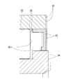
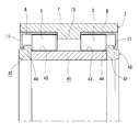
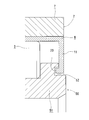
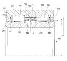
- Sectional drawing which shows the double row bearing which concerns on 1st Example of 1st invention. Partial sectional view showing the state before press-fitting the inner part of FIG. Sectional drawing which shows the prior art example with respect to 1st invention Sectional drawing which shows the double row bearing which concerns on 2nd Example of 1st invention. Partial sectional view showing a double row bearing according to a third embodiment of the first invention Partial sectional view showing a double row bearing according to a fourth embodiment of the first invention Sectional drawing which illustrates the state which attached the bearing which concerns on 1st invention to the other apparatus. Sectional drawing which shows the full complement roller bearing which concerns on 5th Example of 2nd invention.
- fitting surfaces are formed on the first inner part, the second inner part, and the inner periphery of the outer part, and these fitting surfaces are shafts.
- the angle of inclination of the fitting surface of the inner part in a state before being fixed to the outer part is larger than the fitting surface of the corresponding outer part. It is set large.
- the press-fit portion of the outer part and the inner part is inclined on the outer diameter side toward the inner side in the axial direction, the inner part is difficult to be removed from the outer part.
- the rolling elements are made of rollers, and the ring parts at both ends each have a flange portion for guiding the rolling elements, the first shield part and the second shield part. Are respectively separated from the corresponding flange portions in the axial direction toward the outside of the bearing.
- the present invention is applied to a roller bearing.
- the flange portions of the ring parts at both ends guide the end faces of the rollers in the nearest row to the corresponding shield portions. Since the corresponding shield part is separated from the corresponding flange part in the axial direction to the outside of the bearing, the inner part does not fall off due to the axial load from the roller during the bearing operation.
- the inner part having the raceway surface is a part that circumscribes the roller
- the inner diameter of the inner part of the inner part that is closer to the bearing than the raceway surface is larger than the circle diameter that circumscribes the roller. For this reason, the end surfaces of the inner parts do not come into contact with each other and wear out.
- the outer part has a middle collar part between the rows of the rolling elements, and the first inner part and the second inner part are each the middle collar part. Has been hit.
- the inner part when the inner part is press-fitted into the inner periphery of the outer part, the inner part can be fixed at an accurate position.
- the ring components at both ends have the raceway surface of the double-row inner ring and the collar portion, respectively.
- the double row inner ring is divided into a ring component having a raceway surface and a ring component having the collar portion.
- the surface hardness of each of the first inner part and the second inner part on each raceway surface is higher than that of the outer part. According to the sixth embodiment, it is possible to maintain the toughness of the metal outer part while ensuring the bearing life by making the surface hardness of the raceway surface of the inner part higher than that of the outer part.
- the surface hardness of the outer part is HRC55 or less. According to the seventh embodiment, since the outer part has a surface hardness of HRC (Rockwell hardness C scale) 55 or less, the outer part can be given good toughness and cracking of the outer part can be prevented.
- HRC Rockwell hardness C scale
- the first shield part and the second shield part each form a labyrinth together with the wheel part.
- a non-contact seal can be provided using the shield part.
- the first shield part and the second shield part each have a seal lip formed of a seal material, and the seal lip contacts the wheel part. ing.
- the contact seal can be provided using the shield portion.
- the inner diameter of the ring is smaller than the pitch circle diameter of the roller, and the outer diameter of the ring is larger than the pitch circle diameter of the roller. ing.
- the annular surface of the ring is located in the radial region on the greasing port side, and the ring extends to the radial region on the opposite side. For this reason, the tenth embodiment can reduce the amount of grease that can be solidified in the opposite radial region.
- the full complement roller bearing according to the eleventh embodiment further includes a middle collar that defines the width of the inter-row space, and the middle collar is located in a radial area opposite to the radial area on the greasing port side.
- the ring is guided in the radial direction.
- the amount of grease that can be solidified in the inter-row space can be reduced by the amount of the middle collar and the ring in the radial region on the opposite side to the greasing port side of the inter-row space.
- the eleventh embodiment can prevent the flow of grease reaching the collar from the annular surface through the radial region on the greasing port side from being obstructed by the guide contact portion of the ring.
- the annular surface of the ring that faces the greasing port in the radial direction gradually approaches the greasing port in the axial direction toward the collar. It has a surface shape.
- the flow of the grease separated from both sides of the annular surface is directly directed to the collar due to the surface shape of the portion. It can be changed to an easier orientation. Therefore, in the twelfth embodiment, the grease that has hit the annular surface can be positively directed directly to the pair of collars.
- the inter-row space further has a drain port opposed in the radial direction, and the drain port is a radial region on the opposite side to the radial region on the greasing port side.
- the ring has a peripheral surface that forms a flow path from both ends of the width of the ring to the drain port, and the peripheral surface gradually moves to the drain port in the axial direction toward the drain port. It has a surface shape with an approaching part.
- the grease that has flowed into the inter-row space from the greasing port wraps around the radial region on the opposite side to the radial region on the greasing port side so as to bypass the ring, It becomes easy to flow through the flow path along the peripheral surface of the ring and reach the drain port. For this reason, the thirteenth embodiment can prevent the grease that has flowed from the greasing port into the inter-row space from being discharged from the drain port across the inter-row space in the radial direction and becoming wasteful waste grease. .
- the ring is made of resin. According to the fourteenth embodiment, even if the ring comes into contact with the roller, the resin surface portion of the ring comes into contact, so that it is possible to prevent the roller from being worn.
- the ring is formed of an oil-containing polymer material. According to the fifteenth embodiment, since the oil-impregnated polymer is used as the resin, the friction of the ring is reduced by the oil content of the ring compared to the fifteenth embodiment, and the wear of the roller can be further prevented. it can.
- this double row bearing includes a double row inner ring 1, a double row outer ring 2, and rolling elements 3 arranged in a double row.
- the double row inner ring 1 is divided into two wheel parts 4 and 4 arranged in the axial direction.
- a series of annular spaces 5 surrounded by the outer periphery of the double-row inner ring 1 and the inner periphery of the double-row outer ring 2 are inside the bearing.
- the wheel part 4 is composed of an annular part, and has a single row of raceway surfaces 6 on the outer peripheral side thereof.
- the two wheel parts 4 and 4 are symmetrical in the axial direction. These two wheel parts 4 and 4 are arranged coaxially in the axial direction. Since the double-row inner ring 1 has a two-part structure, these two wheel parts 4 and 4 are wheel parts located at both ends of the double-row inner ring 1.
- the axial direction means a direction along the bearing central axis, and coincides with the central axis of the wheel part 4.
- a direction perpendicular to the axial direction is referred to as a radial direction
- a circumferential direction around the central axis is referred to as a circumferential direction.
- the double-row outer ring 2 is divided into an outer part 7 and two inner parts 8 and 8. These two inner parts 8 and 8 are symmetrical in the axial direction. Hereinafter, when these inner parts 8, 8 are called, they are referred to as a first inner part 8 and a second inner part 8. Also, when calling out those parts, call them together.
- the outer part 7 is an integral annular part having an outer periphery 9 and an inner periphery 10.
- the outer periphery 9 of the outer part 7 is an outer diameter surface that defines the outer diameter of the double-row outer ring 2.
- the inner part 8 is an integral annular part having a shield part 11 and a raceway surface 12.
- the shield portion 11 is formed in an inner collar shape that is bent from the extension of the raceway surface 12 of the inner component 8.
- the first shield part 11 and the second shield part 11 each extend to the side of the double-row inner ring 1.
- the first inner part 8 is fixed by press-fitting to the right side of the inner periphery 10 of the outer part 7 in the figure.
- the second inner part 8 is fixed by press-fitting to the left side of the inner periphery 10 of the outer part 7 in the figure.
- the axial direction corresponds to the horizontal direction in the figure.
- the rolling element 3 is interposed between the raceway surface 6 of the double-row inner ring 1 and the raceway surface 12 of the double-row outer ring 2.
- the rolling element 3 consists of rollers. More specifically, the rolling element 3 is a cylindrical roller. For this reason, each of the raceway surfaces 6 and 12 is a surface along the axial direction.
- the ring parts 4 and 4 at both ends each have a flange portion 13 for guiding the rolling elements 3 in the nearest row.
- the collar portion 13 receives one end face 14 of the rolling element 3 in the axial direction.
- the outer part 7 has a middle collar portion 15 between the rows of the rolling elements 3.
- the middle collar portion 15 receives an end surface 16 opposite to the end surface 14 of the rolling element 3 in the axial direction.
- the axial load is applied to the middle flange portion 15 of the double-row outer ring 2 and is not applied to the inner part 8. As long as this is done, the inner part 8 does not come off due to the axial load, and the double-row inner ring may or may not have a middle collar portion.
- mating surfaces 17 are formed on both sides of the middle brim portion 15 as a boundary.
- the inner part 8 has a fitting surface 18 corresponding to the fitting surface 17.
- These fitting surfaces 17 and 18 are surfaces inclined toward the outer diameter side of the double-row outer ring 2 in the axial direction toward the bearing inner side.
- the inner part 8 is fixed to the outer part 7 by press-fitting between the fitting surface 17 of the outer part 7 and the fitting surface 18 of the inner part 8.
- FIG. 2 shows a state of the first inner part 8 in a state before being fixed to the outer part 7.
- the fitting surface 18 of the first inner component 8 in a state before being fixed to the outer component 7 is formed in a conical surface shape having an inclination angle ⁇ 1 with respect to the axial direction.
- the fitting surface 17 of the outer part 7 is formed in a conical surface shape having an inclination angle ⁇ with respect to the axial direction.
- the inclination angle ⁇ 1 is set larger than the inclination angle ⁇ .
- the raceway surface 12 of the first inner part 8 is also formed in a conical surface shape having an inclination angle ⁇ 2 on the outer diameter side of the double-row outer ring 2 toward the bearing inner side in the axial direction.
- the inclination angle ⁇ 2 is smaller than the inclination angle ⁇ 1.
- the first inner part 8 When the first inner part 8 is press-fitted, the first inner part 8 is deformed into a state drawn in a two-dot chain line in FIG. 2 (state shown in FIG. 1). That is, when the fitting surface 18 of the first inner component 8 is press-fitted into the fitting surface 17 of the outer component 7, the fitting surface 18 of the first inner component 8 follows the fitting surface 17 (the fitting surface). 18 is ⁇ ), and the raceway surface 12 of the first inner component 8 is in a state along the axial direction. Thereby, the state which made the compressive stress act on the track surface 12 of the 1st inner component 8 is obtained.
- 2 illustrates the first inner part 8, but the fitting relationship between the second inner part 8 on the left side in FIG. 1 and the outer part 7 is symmetrical with the case of FIG. 2 in the axial direction. Therefore, the illustration is omitted.
- the two inner parts 8, 8 are respectively abutted against the middle collar portion 15 by the aforementioned press-fitting.
- the end surface 19 connecting the raceway surface 12 of the inner component 8 and the fitting surface 18 is in contact with the middle collar portion 15 in the axial direction, and the fixing position of the inner component 8 in the axial direction is determined.
- the shield part 11 has a locking end face 20 that faces the corresponding wheel part 4 with a slight gap in the axial direction.
- the axial movement of the wheel parts 4, 4 at both ends is restricted by the locking end surfaces 20, 20 of the two shield parts 11.
- the row of the ring component 4 and the rolling element 3 is coaxially arranged inside the outer component 7, and the inner component 8 is inserted from the end surface 19 between the rolling element 3 and the fitting surface 17 of the outer component 7.
- the inner part 8 is fixed to the outer part 7 and the wheel part 4 is prevented from being separated from the outer part 7 in the axial direction to the bearing outer side. Can do. Therefore, when the two inner parts 8 and 8 are press-fitted simultaneously or separately, the shield parts 11 and 11 of the two inner parts 8 and 8 fixed to each other and the ring parts 4 and 4 at both ends of the double-row inner ring 1 are fixed.
- a locking structure that prevents separation of the double-row inner ring 1 and the double-row outer ring 2 is provided.
- the shield part 11 is opposed to the corresponding wheel part 4 with a slight gap in the axial direction and the radial direction, and is continuous over the entire circumference in the circumferential direction between the inner diameter surface 21 and the fitting surface 18. . For this reason, the shield part 11 can exhibit a protective function corresponding to the shield.
- the outer part 7 described above is made of metal.
- the surface hardness of the outer part 7 is HRC55 or less. This Rockwell hardness is ensured over the entire outer part 7.
- Examples of the material of the outer part 7 include carbon steel.
- the inner part 8 is made of metal.
- the surface hardness of each of the two inner parts 8 and 8 on each raceway surface 12 is higher than that of the outer part 7.
- One cause of fatigue failure of the bearing is that the tensile stress repeatedly acts on the raceway surface to cause separation. It is known that the lifetime can be extended if compressive stress is applied beforehand. For example, it is preferable to apply a compressive stress to the surface by performing a carburizing heat treatment.
- the inner part 8 is formed by press working.
- the inner part 8 is formed by squeezing, bottom drilling, or flange punching.
- the material of the inner part 8 is, for example, a member having a good surface roughness such as polished steel (prepared steel bar specified by JIS, polished special band steel). It is preferable. Thereby, polishing processing can be reduced.
- the double-row bearing according to the first embodiment is assembled to the double-row outer ring 2 simply by press-fitting the raceway surface 12 on the double-row outer ring 2 side and the inner parts 8, which also serve as shields, into the outer part 7.
- a structure for locking the double-row inner ring 1 in the axial direction by the inner parts 8 and 8 can be provided, and separation of the double-row inner ring 1 and the double-row outer ring 2 can be prevented.
- the double row bearing according to the first embodiment can be easily assembled.
- the metal inner parts 8 and 8 are heat-treated separately from the outer part 7, and the surface hardness of the raceway surface 12 of the inner part 8 is higher than that of the outer part 7.
- the double row bearing according to the first embodiment can achieve both the bearing life and the difficulty of cracking the double row outer ring 2.
- the inner part 8 having the raceway surface 12 can greatly expand the press-fitting portion with the outer part 7 as compared with the conventional shield. For this reason, even if the shield part 11 of the inner part 8 receives the sealing pressure of the lubricant at the time of regreasing, the inner part 8 that is press-fitted in the fitting surface 18 on the back side of the raceway surface 12 does not easily fall off. . Therefore, the double row bearing according to the first embodiment can prevent the situation where the protection inside the bearing by the shield portion 11 is lost during regreasing.
- the double row bearing according to the first embodiment applies a compressive stress to the raceway surface 12 when the inner part 8 is press-fitted, the bearing life is extended and the outer part 7 and the inner part are fixed in the fixed state by the press-fitting. Since the fitting surfaces 17 and 18 of FIG. 8 are inclined at the inclination angle ⁇ in the axial direction toward the inside of the bearing toward the outer diameter side, the inner part 8 can be made difficult to come off from the outer part 7.
- the outer part 7 has the middle collar part 15 between the rows of the rolling elements 3, 3, and the two inner parts 8, 8 project respectively into the middle collar part 15. Therefore, when these inner parts 8 and 8 are press-fitted into the inner periphery of the outer part 7, the inner parts 8 can be fixed at an accurate position only by being inserted until they abut against the middle collar portion 15. .
- the outer part 7 since the outer part 7 has a surface hardness of HRC55 or less, the outer part 7 can be given good toughness and can be prevented from cracking.
- the double-row inner ring 1 is divided into rows, and the ring parts 4 and 4 at both ends have the raceway surface 6 and the collar portion 13, respectively. It may be structured.
- a second embodiment as an example will be described with reference to FIG. In the following second to fourth embodiments, only differences from the first embodiment will be described.
- the double-row inner ring 40 is divided into a center ring part 41 and ring parts 42 and 42 at both ends.
- the center wheel part 41 has a cylindrical shape having two rows of raceway surfaces 43 and 43.
- the ring parts 42 and 42 at both ends each have a flange portion 44.
- the wheel parts 42 and 42 at both ends are butted against the center wheel part 41 in the axial direction. Separation of the double-row inner ring 40 and the double-row outer ring 2 is prevented by the axial and radial engagement between the shield parts 11 and 11 of the two inner parts 8 and 8 and the ring parts 42 and 42 at both ends. .
- the inner part 8 is simply a shield, but it is also possible to provide a seal that seals between the double-row inner ring and the double-row outer ring using the inner part.
- a third embodiment as an example will be described with reference to FIG.
- a circumferential groove portion 52 having a depth in the axial direction is formed in the ring component 51 at the end of the double row inner ring 50.
- the locking end surface 20 of the shield part 11 enters the inside of the circumferential groove part 52 and opposes the groove bottom surface of the circumferential groove part 52 in the axial direction.
- the vicinity of the locking end surface 20 of the shield part 11 and the vicinity of the peripheral groove part 52 of the end wheel part 51 form a labyrinth composed of uneven channels in the axial direction, and the pressure loss of the flow passing therethrough Increase the amount of lubricant leakage.
- the double row bearing according to the third embodiment can be provided with a non-contact seal using the shield portion 11.
- a double row bearing according to a fourth embodiment will be described with reference to FIG.
- the double row bearing according to the fourth embodiment has a seal lip 61 provided in the shield part 11.
- the ring component 62 at the end of the double-row inner ring 60 has a cylindrical seal surface 63 that contacts the seal lip 61.
- the seal lip 61 is formed of a seal material attached to the inner diameter surface 21 of the shield part 11.
- the sealing material is made of an elastomer having elasticity such as rubber.
- As the sealing material various materials that are common as contact seals for bearings can be appropriately employed.
- the metal shield part 11 serves as a cored bar.
- the fourth embodiment can provide a contact seal using the shield portion 11.
- the full-roller type double-row cylindrical roller bearing is exemplified.
- the present invention may be applied to other types of double-row bearings.
- FIG. 7 illustrates a state where the double row bearing B according to any of the above-described embodiments is attached to the counterpart device.
- the illustrated counterpart device is a support device for the crane sheave 101.
- the double row bearing B supports the support shaft 100 rotatably with respect to the crane sheave 101.
- the support shaft 100 is passed through the shaft holes of the pair of housing side plates 102.
- the pair of housing side plates 102 are reinforced in the axial direction by bolts 103 and nuts 104.
- the support shaft 100 is prevented from coming off by a retaining ring 105 with respect to the pair of housing side plates 102.
- the double row bearings B are arranged in pairs for each crane sheave 101. A large number of double row bearings B are arranged in the axial direction along the support shaft 100.
- each double row bearing B is fixed by the other adjacent double row bearing B and the external member of the housing side plate 102.
- the double row bearing B is attached to the support shaft 100, since the double row inner ring and the double row outer ring are non-separable due to the above-described locking, the attachment can be facilitated.
- the double-row inner ring is fixed in the axial direction by the external part, so that even when an axial load is applied to the double-row bearing B, the inner part may receive a force in the axial direction. There is no concern that the shield part will be broken or the inner part will come off.
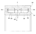
- this full roller bearing includes an inner double row raceway ring 201, an outer double row raceway ring 202, rollers 203 arranged in a double row, a sealing device 204, 204.
- the inner double row raceway ring 201 is formed of an integrally formed annular part, and has two rows of raceway surfaces 205 and 205 on the outer peripheral side thereof, and a greasing port 206 positioned between these raceway surfaces 205 and 205. And a pair of flanges 207, 207 facing in the axial direction.
- the collar 207 protrudes in the radial direction from the inner raceway surface 205.
- the collar 207 has an outer peripheral surface that defines the outer diameter of the inner double row raceway ring 201.
- the axial direction refers to the direction along the bearing central axis, and coincides with the central axis of the double row races 201 and 202.
- a direction perpendicular to the axial direction is referred to as a radial direction
- a circumferential direction around the central axis is referred to as a circumferential direction.
- the width refers to the length measured in the axial direction.
- the outer double-row raceway ring 202 is formed of an annular part formed integrally, and has two rows of raceway surfaces 208 and 208 on the inner peripheral side thereof, and a middle collar 209 located between these raceway surfaces 208 and 208. And have.
- the sealing device 204 is disposed between the inner double row raceway ring 201 and the outer double row raceway ring 202.
- the sealing device 204 is located outside the contact position of the nearest flange 207 or 203 with respect to the axial direction.
- the sealing device 204 prevents leakage of grease from the space between the double row races 201 and 202 and prevents foreign matter from entering from the outside.
- the sealing device 204 is formed by a contact seal that is fixed to the inner peripheral end portion of the outer double row raceway ring 202 by press-fitting and contacts the outer peripheral surface of the collar 207.
- the roller 203 is composed of a cylindrical roller interposed between the inner raceway surface 205 and the outer raceway surface 208.
- the double row rollers 203 and 203 are disposed between the pair of collars 207 and 207.
- Each row of rollers 203 is guided by a middle collar 209 and a nearest collar 207.
- the surfaces at both ends of the middle collar 209 guide the opposite end surfaces of the double row rollers 203 and 203. For this reason, the width of the inter-row space A of the double-row rollers 203, 203 coincides with the width of the middle collar 209. That is, the middle collar 209 defines the width of the inter-column space A.
- the greasing port 206 includes a greasing route connected to a grease supply system (not shown) outside the bearing.
- the illustrated greasing port 206 is an oil hole that faces the inter-row space A in the radial direction.
- the inner double row raceway ring 201 has a series of cylindrical portions including two rows of raceway surfaces 205 and 205 and a greasing port 206.
- the greasing port 206 penetrates between the inner and outer diameters of the cylindrical portion of the inner double row raceway ring 201.
- the greasing port 206 is formed at a plurality of locations in the circumferential direction.
- the pair of collars 207 and 207 are located in a radial region on the greasing port 206 side with the pitch circle diameter (PCD) of the roller 203 as a boundary.
- the pitch circle diameter (PCD) of the rollers 203 refers to the diameter of the circumference passing through the center of the roller length on the roller central axis of a row of rollers 203 interposed between the inner and outer raceways 205 and 208.
- the radial region on the greasing port 206 side with the pitch circle diameter (PCD) of the roller 203 as a boundary corresponds to the range of the arrow line indicating “PCD” in the vertical direction in FIG.
- the full complement roller bearing according to the fifth embodiment has a ring 210 arranged in the inter-row space A.
- the ring 210 is continuous over the entire circumference in the illustrated sectional shape.
- the greasing port 206 faces the ring 210 in the radial direction over the entire width of the greasing port 206.
- Both end surfaces defining the width of the ring 210 are flat surfaces along the radial direction.
- the width of the ring 210 is equal to or less than the width of the middle collar 209. For this reason, even if the ring 210 and 203 come into contact with each other during bearing operation, the ring 210 does not receive an axial load.
- the ring 210 is arranged so as to freely move in the axial direction in the inter-row space A.
- the axial movement of the ring 210 is regulated by the double row rollers 203 and 203.
- the width of the ring 210 is preferably as large as possible. In the illustrated example, the width of the ring 210 is set to a limit size that does not receive an axial load.
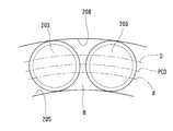
- the inner diameter d of the ring 210 is smaller than the PCD.
- the outer diameter D of the ring 210 is larger than that of PCD.
- the ring 210 has an annular surface 211 located in the region of the greasing port 206 side in the entire width of the ring 210.
- the radial clearance between the annular surface 211 of the ring 210 and the greasing port 206 is larger than the radial clearance between the ring 210 and the middle collar 209, and the ring 210 is radially expanded by the inner double row raceway ring 201. You will not be guided.
- the middle brim 209 located in the region opposite to the greasing port 206 has a cylindrical ring guide surface that faces the ring 210 in the radial direction.
- the ring 210 is guided in the radial direction by contact with the ring guide surface of the middle collar 209. The purpose of this guidance is to keep the radial clearance between the annular surface 211 and the greasing port 206 within a predetermined range.
- a predetermined range on both sides from the center of the width of the annular surface 211 becomes a portion facing the greasing port 206 in the radial direction as the ring 210 moves in the axial direction.
- At least the facing portion of the annular surface 211 has a surface shape that gradually approaches the greasing port 206 toward the collar 207 in the axial direction.
- the central portion of the annular surface 211 has a circular arc shape that is concave on the upper side in FIG. 8.
- the ring 210 is made of resin.
- As the resin an oil-containing polymer material containing a lubricating oil is employed.
- the above resins are, for example, peak (PEEK), PP (PPS), polyphenylsulfone (PPSU), polysulfone (PSU), polyethersulfone (PESU), polyarylate (PAR), polyamideimide (PAI), poly Etherimide (PEI, eg Ultem®), liquid crystal polymer (LCP), polytetrafluoroethylene (PTFE), polychlorotrifluoroethylene (PCTFE), polyvinylidene fluoride (PVDF), 6 nylon (PA6), 66 Nylon (PA66), polyacetal (POM), polycarbonate (PC), polyethylene terephthalate (PET), modified PPE (m-PPE, or modified PPO), polybutylene terephthalate (PBT), ultra high molecular weight polyethylene (U-PE), Polyvinyl chloride (PVC), polyethylene (PE), polypropylene (PP), polystyrene (PS), ABS (ABS), AS (AS), acrylic (PMMA),
- the grease Gr flows in the bearing internal space between the inner and outer double-row race rings 201 and 202.
- the flow of the grease Gr is conceptually indicated by an arrow line in FIG.
- the grease flow generally has the following flow path. That is, the grease Gr that has flowed out from the greasing port 206 into the inter-row space A collides with the annular surface 211 of the ring 210 that faces the entire width of the greasing port 206.
- the flow of the grease Gr that collides is divided on both sides in the axial direction.
- the flow of the grease Gr hitting the collar 207 bends in the radial direction and travels toward the region opposite to the greasing port 206 through the space between the end face of the roller 203 guided by the collar 207 and the sealing device 204.
- the grease Gr that has passed through becomes difficult to flow linearly to the sealing device 204 toward the outside of the bearing, so that grease leakage from the sealing device 204 is prevented during lubrication, and the lubrication efficiency is improved.
- the sealing device 204 is less likely to receive the fluid pressure of the grease Gr directly in the axial direction, the sealing device 204 is prevented from falling off.
- the volume of the ring 210 occupying the inter-row space A can reduce the amount of grease that can be solidified in the inter-row space A during the bearing operation. For this reason, it becomes easy to replace the grease Gr in the inter-row space A at the time of regreasing, thereby preventing poor lubrication after regreasing.
- the full complement roller bearing according to the fifth embodiment improves the efficiency in supplying the grease Gr to the double row inter-row space A and prevents the sealing device 204 from falling off. It is possible to prevent poor lubrication.
- the annular surface 211 of the ring 210 is located in the region of the greasing port 206 side, The ring 210 also extends to the region opposite to the greasing port 206. For this reason, the full complement roller bearing according to the fifth embodiment can reduce the amount of grease that can be solidified in the region opposite to the greasing port 206 in the inter-row space A.
- the amount of grease that can be solidified in the inter-row space A is particularly anti-feed due to the presence of the intermediate collar 209 and the ring 210 in the region of the anti-grease port 206 in the inter-row space A It can be reduced in the region of the fat mouth 206 side.
- the middle collar 209 located in the region opposite to the greasing port 206 guides the ring 210 in the radial direction, the ring 210 is not brought into guiding contact with other bearing components in the region serving as the grease supplying port 206. For this reason, the full complement roller bearing according to the fifth embodiment does not obstruct the flow of the grease Gr reaching the collar 207 from the annular surface 211 through the region of the greasing port 206 at the guide contact portion of the ring 210.
- the annular surface 211 of the ring 210 that is opposed to the greasing port 206 in the radial direction has a concave arc surface shape that gradually approaches the greasing port 206 toward the flange 207 in the axial direction.
- the flow of the grease Gr separated from both sides is changed to a direction that makes it easy to directly face the collar 207 by the concave arc surface shape.
- the full complement roller bearing according to the fifth embodiment can positively direct the grease Gr striking the annular surface 211 directly to the pair of collars 207 and 207.
- the concave arc surface shape is adopted, but other surface shapes are adopted as long as the direction of the flow of grease Gr is positively changed to approach the direction facing the collar 207 depending on the surface shape. May be.
- it may be a surface shape having an inverted V-shaped cross section.
- the ring 210 is formed of a resin, particularly an oil-containing polymer material, even if the ring 210 contacts the roller 203, the oil-impregnated resin surface 3 of the ring 210 is Because of the contact, it is possible to particularly prevent the rollers 203 from being worn.
- a sixth embodiment according to the second invention will be described with reference to FIGS. Hereinafter, only differences from the fifth embodiment will be described.
- the ring 210 ′ according to the sixth embodiment has a peripheral surface 213 that forms a flow path 212 between the ring 210 ′ and the middle brim 209 ′ located in the region opposite to the greasing port 206 ′.
- a drain port 214 that is opposed to the inter-row space A in the radial direction is provided.
- the drain port 214 includes a greasing route for discharging grease Gr to be discarded from the bearing internal space to the outside of the bearing when regreasing from the greasing port 206 ′.
- the drain port 214 penetrates radially between the inner and outer diameters of the outer double row raceway ring 202 ′.
- the peripheral surface 213 of the ring 210 ′ forms a flow path 212 from both ends of the width of the ring 210 ′ to the drain port 214.
- the peripheral surface 213 has a surface shape having an inverted V-shaped section that gradually approaches the drain port 214 in the axial direction toward the drain port 214.
- the greasing port 206 ′ is narrower than the fifth embodiment in order to increase the pressure of the grease Gr flowing out from here to the inter-row space A.
- the grease Gr that has flowed into the inter-row space A from the greasing port 206 ′ bypasses the ring 210 ′, and the anti-greasing port 206 ′ from the region of the greasing port 206 ′. Wrap around the side area.
- the entrained grease Gr is directed to the flow path 212 formed between the ring 210 ′ and the intermediate collar 209 ′ by the peripheral surface 213 of the ring 210 ′.
- the grease Gr flowing through the flow path 212 along the peripheral surface 213 collides with a reverse V-shaped portion of the peripheral surface 213 and easily reaches the drain port 214.
- the grease Gr flowing into the inter-row space A from the greasing port 206 ′ is discharged from the drain port 214 across the inter-row space A in the radial direction, and is wasted. Grease can be prevented.
- the inner double-row raceway and the outer double-row raceway are integrated annular parts, but these are divided into single-row raceway surfaces. It may be an appropriate divided structure divided into a race ring, a collar formed with a collar, a spacer interposed between the split race rings, a fastening member that couples the split race rings, and the like. When employing spacers or fastening members that form inter-column spaces, they may be provided with a greasing port. Further, the middle collar may be provided on the inner side of the double-row raceway. Further, in each of the above-described embodiments, the greasing port is provided on the inner double row raceway side, but may be provided on the outer double row raceway side.
Landscapes
- Engineering & Computer Science (AREA)
- General Engineering & Computer Science (AREA)
- Mechanical Engineering (AREA)
- Rolling Contact Bearings (AREA)
Abstract
複列外輪(2)を、金属製のアウター部品(7)と、シールド部(11)及び軌道面(12)を有する金属製の二つのインナー部品(8、8)とに分割する。二つのインナー部品(8、8)を、それぞれアウター部品(7)の内周に圧入することによって固定し、各軌道面(12、12)での表面硬度をアウター部品(7)よりも高くする。シールド部(11、11)をそれぞれ複列内輪(1)の側方まで延ばし、これらと複列内輪(1)の両端の輪部品(4、4)との係止によって、複列内輪(1)と複列外輪(2)の分離を防ぐ係止構造を設ける。
Description
第一の発明は、複列軸受に関し、特に、複数の輪部品に分割された複列内輪を備えるものに関する。第二の発明は、総ころ軸受に関し、特に、複列のころの列間空間にグリースを供給するものに関する。
従来、複列軸受には、軸方向に並ぶ二つの内輪を予め締結部材で結合することによって複列内輪として一体化したものがある。この一体化の目的は、複列軸受を相手装置に組み込むまでの取り扱い性を良くすることにある。このような複列軸受では、軸を支持する使用状態のとき、二つの軌道輪が、他の軸受、間座、ハウジング、蓋、止め輪等の外部部材によって固定される。したがって、締結部材による結合は、複列軸受を相手装置に取り付けるまで維持可能な程度でよく、一般に、軸受の自重で結合が破壊されない程度になっている。
例えば、クレーンシーブ用の総ころ形複列円筒軸受において、薄い金属製の締結環を二つの輪部品の周溝に沿ってローリングプレス加工で加締めることにより、これら輪部品を結合している(下記特許文献1)。
また、特許文献1に開示された複列の総ころ軸受は、各列のころ間のすきまの和がころ直径を超えず、かつ保持器をもたない転がり軸受として構成されている。
この種の総ころ軸受の中でも、グリース潤滑で使用されるものは、軸受内部空間からのグリースの漏洩を防止する密封装置を備えている。複列のころは、軸方向に向き合う対のつば間に配置されているので、軸受運転中に密封装置と接触しない。軸受内部空間への給脂を可能とするため、複列の列間空間に直接にグリースを供給する給脂口が採用されている。
例えば、図12に示すように、内方の複列軌道輪201と外方の複列軌道輪202間に複列のころ203、203が介在し、これら複列軌道輪201、202間の軸受内部空間の両端にそれぞれ密封装置204が配置され、複列軌道輪201の軌道面205、205間の中間に給脂口206が設けられる。
しかしながら、上述のような締結環を用いる場合、組立工数が大きくなる点で問題がある。
また、複列外輪に衝撃荷重が作用する場合があり、割れ対策としてある程度の靱性が必要になる一方、その複列外輪の内側に形成された軌道面には、転動体の転動により繰り返し荷重が働くため、軸受寿命を確保するのに、一定以上の表面硬度が必要になる。このため、複列外輪に熱処理を行って軌道面の表面硬度を高めているが、この際、複列外輪の靱性が犠牲になっていた。
また、軸受内部を保護するため、シールド又はシールを複列内輪もしくは複列外輪の両端に圧入することが好ましいが、この場合、再給脂する際、潤滑剤の封入圧により、シールドが脱落することがあった。
また、上述のような総ころ軸受に給脂を行う場合、給脂効率の低下を招くグリース漏れが発生し易い問題がある。すなわち、図12を例に説明すると、給脂口206から、複列のころの端面間に確保された列間空間Aに直接にグリースGrが供給される。そのグリースGrの流れを図中に概念的に矢線で示すように、グリースGrの流れが複列軌道輪202にぶつかって軸方向両側に分かれる。保持器がないため、分かれたグリースGrの殆どは、周方向に隣接するころ間の空間にスムーズに進入する。この際、多くのグリースGrは、そのころ間の空間のうち、外方の複列軌道輪202側を通過し、そのまま密封装置204にぶつかる。このように、分かれたグリースGrが軸受外部に向かって密封装置204まで直線的に流れ易い軸受内部構造となっているので、密封装置204の密封が負けて給脂中の漏れが発生し易い。また、密封装置204の端面でグリースGrの流動圧を直接に軸方向に受け易く、このため、密封装置204が脱落し易い問題もある。
さらに、グリースGrを封入する際には、直接的に使用されない列間空間Aに多くの量のグリースが封入される。このため、給脂口6からの再給脂によってグリースGrを交換する際にも同じく多くのグリースGrが列間空間Aに封入されてしまう。その列間空間AのグリースGrは、ころ3に攪拌されず、軸受運転中に流動しないため、油分を失って固形化しやすい。固形化すると、グリースを再給脂した場合に、列間空間Aのグリースが新しいグリースに交換されず、潤滑不良を招く恐れがある。
そこで、第一の発明が解決しようとする第一の課題は、二つ以上の輪部品に分割された複列内輪を備える複列軸受の組立を簡単にし、軸受寿命と複列外輪の割れ防止を両立させると共に、軸受内部の保護を再給脂時に喪失する事態を防ぐことにある。
また、第二の発明が解決しようとする第二の課題は、複列の総ころ軸受の列間空間にグリースを給脂する際の効率を良くすると共に密封装置の脱落を防止し、さらに再給脂後の潤滑不良を防止することにある。
上記第一の課題を達成するため、第一の発明は、複列内輪と、複列外輪と、複列に配置された転動体とを備え、前記複列内輪が、軸方向に並ぶ二つ以上の輪部品に分割されている複列軸受において、前記複列外輪が、外周及び内周を有する金属製のアウター部品と、第一のシールド部及び軌道面を有する金属製の第一のインナー部品と、第二のシールド部及び軌道面を有する金属製の第二のインナー部品とに分割されており、前記第一のインナー部品及び第二のインナー部品が、それぞれ前記アウター部品の内周に対する圧入によって固定されており、前記第一のシールド部及び前記第二のシールド部が、それぞれ前記複列内輪の側方まで延びており、前記第一のシールド部及び前記第二のシールド部と、前記複列内輪の両端の前記輪部品との係止によって、前記複列内輪と前記複列外輪の分離を防ぐ係止構造をさらに備える、という第一の構成を採用した。
上記第一の構成によれば、複列外輪側の軌道面とシールドを兼ねたインナー部品をアウター部品に圧入するだけで複列外輪に組み立てると共に、そのインナー部品により複列内輪を軸方向に係止する構造を設け、複列内輪と複列外輪の分離を防ぐことができる。このため、複列軸受の組立が簡単になる。インナー部品の圧入を行うだけなので、例えば、締結環のローリングプレス加工で結合する場合よりも組立工数の削減を図ることが可能である。
また、金属製のインナー部品をアウター部品とは別個に熱処理を行い、金属製のアウター部品には熱処理をしない(又は表面硬度を抑えた熱処理をする)ようにしてアウター部品の靱性を保つことが可能である。すなわち、軸受寿命と複列外輪の割れにくさとが、両立させられる。
また、軌道面を有するインナー部品は、従来のシールドよりもアウター部品との圧入部を大幅に広げることができる。このため、インナー部品のシールド部が、再給脂時に潤滑剤の封入圧を受けても、軌道面の裏側でも圧入されているインナー部品が脱落しにくくなる。したがって、シールド部による軸受内部の保護を再給脂時に喪失する事態も防止される。
上記第二の課題を達成するため、第二の発明は、軸方向に向き合う対のつばと、前記対のつば間に配置された複列のころと、前記複列のころの列間空間に径方向に対向する給脂口と、密封装置と、を有する総ころ軸受において、前記列間空間に配置され、周方向全周に亘って連続するリングをさらに有し、前記給脂口が、当該給脂口の口幅全域で前記リングと対向しており、前記リングが、当該リングの幅全域で前記給脂口側の径方向領域に位置する環状面をもっている、という第二の構成を採用した。
上記第二の構成によれば、給脂口から列間空間にグリースが流出すると、軸受内部空間でグリースの流動が生じる。そのグリース流動は、概ね次のような流動経路になる。すなわち、給脂口から列間空間に流出したグリースは、その給脂口の口幅全域に対向するリングの環状面にぶつかる。ぶつかったグリースの流れは、軸方向両側に分かれる。ここで、リングの幅全域で環状面がころのピッチ円直径を境とした給脂口側の径方向領域に位置しているので、分かれたグリースの流れは、周方向に隣接するころ間の空間のうち、環状面と同側の径方向領域を通り易くなる。このため、通り抜けたグリースの流れは、密封装置にぶつかる前につばにぶつかり易くなる。つばにぶつかったグリースの流れは、径方向へ曲がり、そのつばに案内されるころの端面と密封装置との間の空間を通って反対側の径方向領域に向かう。このように、通り抜けたグリースが軸受外部に向かって密封装置まで直線的に流れにくくなるので、給脂中の漏れが防止され、効率がよくなる。また、密封装置がグリースの流動圧を直接に軸方向に受けにくくなるので、密封装置の脱落も防止される。さらに、列間空間に占めるリングの体積により、列間空間で固形化し得るグリース量を減らすことができる。このため、再給脂時に列間空間のグリースが交換され易くなり、これにより、再給脂後の潤滑不良が防止される。
上述のように、第一の発明に係る複列軸受は、上記第一の構成の採用により、二つ以上の輪部品に分割された複列内輪を備える複列軸受の組立を簡単にし、軸受寿命と複列外輪の割れ防止を両立させると共に、軸受内部の保護を再給脂時に喪失する事態を防ぐことができる。
また、第二の発明に係る総ころ軸受は、上記第二の構成の採用により、複列の総ころ軸受の列間空間にグリースを給脂する際の効率を良くすると共に密封装置の脱落を防止し、さらに再給脂後の潤滑不良を防止することができる。
第一の発明の一例としての第一~第九実施形態を説明する。
第一実施形態に係る複列軸受では、前記第一のインナー部品及び前記第二のインナー部品と、前記アウター部品の内周とに嵌め合い面が形成されており、これら嵌め合い面が、軸方向に軸受内部側に向かって外径側に傾斜しており、前記アウター部品に固定前の状態での前記インナー部品の嵌め合い面の傾斜角度が、対応の前記アウター部品の嵌め合い面よりも大きく設定されている。第一実施形態によれば、アウター部品とインナー部品の圧入部を軸方向内側に向かって外径側に傾斜が付いているので、インナー部品がアウター部品から抜けにくくなる。さらに、アウター部品の嵌め合い面よりも傾斜角度の大きなインナー部品の嵌め合い面を当該アウター部品に圧入すると、インナー部品の軌道面に圧縮応力を働かせることができ、これにより、軸受寿命を延ばすこともできる。
第二実施形態に係る複列軸受では、前記転動体が、ころからなり、前記両端の輪部品が、それぞれ前記転動体を案内するつば部を有し、前記第一のシールド部及び前記第二のシールド部が、それぞれ対応の前記つば部から軸方向に軸受外部側へ離れている。第二実施形態は、この発明をころ軸受に適用したものである。第二実施形態によれば、両端の輪部品のつば部が、対応のシールド部に最寄りの列のころの端面を案内する。その対応のシールド部が軸方向に関して対応のつば部よりも軸受外部側へ離れているので、インナー部品が軸受運転中にころからのアキシアル荷重を受けて抜け落ちることは起こらない。また、軌道面を有するインナー部品はころに外接させる部品であるから、インナー部品のうち、軌道面よりも軸受内部側の部分の内径は、ころに外接する円径よりも大きくなる。このため、インナー部品ところの端面とが接触して、これらが摩耗することも生じない。
第三実施形態に係る複列軸受では、前記アウター部品が、前記転動体の列間に中つば部を有し、前記第一のインナー部品及び前記第二のインナー部品が、それぞれ前記中つば部に突き当てられている。第三実施形態によれば、インナー部品をアウター部品の内周に圧入する際、インナー部品を正確な位置に固定することができる。
第四実施形態に係る複列軸受では、前記両端の輪部品が、それぞれ前記複列内輪の軌道面と、前記つば部とを有する。
第五実施形態に係る複列軸受では、前記複列内輪が、軌道面を有する輪部品と、前記つば部を有する輪部品とに分割されている。
第六実施形態に係る複列軸受では、前記第一のインナー部品及び前記第二のインナー部品の各軌道面での表面硬度が、それぞれ前記アウター部品よりも高くなっている。第六実施形態によれば、インナー部品の軌道面の表面硬度をアウター部品よりも高くすることによって軸受寿命を確保しつつ、金属製のアウター部品の靱性を保つことが可能である。
第七実施形態に係る複列軸受では、前記アウター部品の表面硬度が、HRC55以下になっている。第七実施形態によれば、アウター部品の表面硬度をHRC(ロックウェル硬さ Cスケール)55以下としているので、アウター部品に良好な靭性を与え、アウター部品の割れを防止することができる。
第八実施形態に係る複列軸受では、前記第一のシールド部及び前記第二のシールド部が、それぞれ前記輪部品と共にラビリンスを形成している。第八実施形態によれば、シールド部を利用して非接触シールを設けることができる。
第九実施形態に係る複列軸受では、前記第一のシールド部及び前記第二のシールド部が、それぞれシール材によって形成されたシールリップを有し、前記シールリップが、前記輪部品に接触している。第九実施形態によれば、シールド部を利用して接触シールを設けることができる。
第二の発明の一例としての第十~第十五実施形態を説明する。
第十実施形態に係る総ころ軸受では、前記リングの内径が、前記ころのピッチ円直径よりも小径になっており、前記リングの外径が、前記ころのピッチ円直径よりも大径になっている。第十実施形態によれば、リングの環状面が前記給脂口側の径方向領域に位置すると共に、これと反対側の径方向領域にもリングが及ぶ。このため、第十実施形態は、反対側の径方向領域で固形化し得るグリース量を減らすことができる。
第十一実施形態に係る総ころ軸受では、前記列間空間の幅を定める中つばをさらに有し、前記中つばが、前記給脂口側の径方向領域と反対側の径方向領域に位置し、かつ前記リングを径方向に案内するようになっている。第十一実施形態によれば、列間空間の給脂口側と反対側の径方向領域に中つばとリングがある分、列間空間で固形化し得るグリース量を減らすことができる。また、中つばがリングを径方向に案内するため、リングを他の軸受部品に案内接触させることが不要となる。したがって、第十一実施形態は、環状面から給脂口側の径方向領域を通ってつばまで到達するグリースの流れをリングの案内接触部で阻害しないようにすることができる。
第十二実施形態に係る総ころ軸受では、前記リングの環状面のうち、少なくとも前記給脂口と径方向に対向する部分が、軸方向に前記つばに向かって次第に当該給脂口に接近する面形状になっている。第十二実施形態によれば、環状面の給脂口と径方向に対向する部分にグリースがぶつかると、ここから両側に分かれるグリースの流れが、当該部分の面形状により、つばに直接に向かい易くなる向きへ変えられる。このため、第十二実施形態は、環状面にぶつかったグリースを積極的に対のつばへ直接に向かわせることができる。
第十三実施形態に係る総ころ軸受では、前記列間空間に径方向に対向するドレン口をさらに有し、前記ドレン口が、前記給脂口側の径方向領域と反対側の径方向領域に位置しており、前記リングが、当該リングの幅両端から前記ドレン口まで流路を形成する周面を有し、前記周面が、軸方向に前記ドレン口に向かって次第に当該ドレン口に接近する部分をもった面形状になっている。第十三実施形態によれば、給脂口から列間空間に流出したグリースが、リングを迂回するように、給脂口側の径方向領域と反対側の径方向領域に回り込んでから、リングの周面に沿った流路を流れてドレン口に達し易くなる。このため、第十三実施形態は、給脂口から列間空間に流出したグリースが列間空間を径方向に亘ってドレン口から排出され、無駄な廃棄グリースになるのを防止することができる。
第十四実施形態に係る総ころ軸受では、前記リングが、樹脂によって形成されている。
第十四実施形態によれば、リングがころと接触したとしても、リングの樹脂表面ところが接触するため、ころの摩耗を防止することができる。
第十四実施形態によれば、リングがころと接触したとしても、リングの樹脂表面ところが接触するため、ころの摩耗を防止することができる。
第十五実施形態に係る総ころ軸受では、前記リングが、含油高分子材によって形成されている。第十五実施形態によれば、樹脂として含油高分子を採用しているので、リングの含油分でリングところの摩擦を第十五実施形態よりも軽減し、ころの摩耗をより防止することができる。
以下、第一の発明の第一実施例に係る複列軸受を添付図面の図1、図2に基づいて説明する。図1に示すように、この複列軸受は、複列内輪1と、複列外輪2と、複列に配置された転動体3とを備える。複列内輪1は、軸方向に並ぶ二つの輪部品4、4に分割されている。複列内輪1の外周と複列外輪2の内周とで囲まれた一連の環状空間5が、軸受内部となっている。
輪部品4は、環状部品からなり、その外周側に単列の軌道面6を有する。二つの輪部品4、4は、軸方向に対称な形状のものとなっている。これら二つの輪部品4、4は、軸方向に同軸で並んでいる。複列内輪1が二分割構造になっているので、これら二つの輪部品4、4が、複列内輪1の両端に位置する輪部品となる。
ここで、軸方向とは、軸受中心軸に沿った方向のことをいい、輪部品4の中心軸に一致している。以下、その軸方向に直角な方向のことを径方向といい、その中心軸周りの円周方向のことを周方向という。
複列外輪2は、アウター部品7と、二つのインナー部品8、8とに分割されている。これら二つのインナー部品8、8は、軸方向に対称な形状のものとなっている。以下、これらインナー部品8、8を呼び分けるときは、第一のインナー部品8と、第二のインナー部品8という。また、それらの部分を呼び分けるときも同じく呼び分ける。
アウター部品7は、外周9及び内周10を有する一体の環状部品からなる。アウター部品7の外周9は、複列外輪2の外径を規定する外径面となっている。
インナー部品8は、シールド部11及び軌道面12を有する一体の環状部品からなる。シールド部11は、インナー部品8の軌道面12の延長上から曲がった内鍔状に形成されている。
第一のシールド部11及び第二のシールド部11は、それぞれ複列内輪1の側方まで延びている。
第一のインナー部品8は、アウター部品7の内周10の図中右側に圧入によって固定されている。第二のインナー部品8は、アウター部品7の内周10の図中左側に圧入によって固定されている。なお、軸方向は、図中左右方向に相当する。
転動体3は、複列内輪1の軌道面6と、複列外輪2の軌道面12との間に介在している。転動体3は、ころからなる。より具体的には、転動体3は、円筒ころになっている。このため、軌道面6、12は、それぞれ軸方向に沿った表面となっている。
両端の輪部品4、4は、それぞれ最寄りの列の転動体3を案内するつば部13を有する。つば部13は、転動体3の一方の端面14を軸方向に受ける。
一方、アウター部品7は、転動体3の列間に中つば部15を有する。中つば部15は、転動体3の端面14と反対の端面16を軸方向に受ける。アキシアル荷重は複列外輪2の中つば部15に負荷され、インナー部品8に負荷されない。このようにする限り、アキシアル荷重でインナー部品8が抜けることはなく、複列内輪については中つば部の有無を問わない。
アウター部品7の内周10のうち、中つば部15を境とした両側に、それぞれ嵌め合い面17が形成されている。一方、インナー部品8には、嵌め合い面17に対応の嵌め合い面18が形成されている。これら嵌め合い面17、18は、それぞれ軸方向に軸受内部側に向かって複列外輪2の外径側に傾斜している表面となっている。アウター部品7の嵌め合い面17と、インナー部品8の嵌め合い面18との圧入嵌合によって、インナー部品8がアウター部品7に固定される。
図2に、アウター部品7に固定する前の状態での第一のインナー部品8の様子を示す。同図に示すように、アウター部品7に固定前の状態での第一のインナー部品8の嵌め合い面18は、軸方向に対して傾斜角度α1をもった円すい面状に形成されている。一方、アウター部品7の嵌め合い面17は、軸方向に対して傾斜角度βをもった円すい面状に形成されている。傾斜角度α1は、傾斜角度βよりも大きく設定されている。
また、第一のインナー部品8の軌道面12も、軸方向に軸受内部側に向かって複列外輪2の外径側に傾斜角度α2をもった円すい面状に形成されている。傾斜角度α2は、傾斜角度α1よりも小さい。
第一のインナー部品8の圧入時、第一のインナー部品8が図2中に二点鎖線で描いた状態(図1の状態)に変形させられる。すなわち、第一のインナー部品8の嵌め合い面18がアウター部品7の嵌め合い面17に圧入されると、第一のインナー部品8の嵌め合い面18が嵌め合い面17に倣い(嵌め合い面18の傾斜角度がβになる。)、かつ第一のインナー部品8の軌道面12が軸方向に沿った状態となる。これにより、第一のインナー部品8の軌道面12に圧縮応力を働かせた状態が得られる。なお、図2では第一のインナー部品8を例示したが、図1中左側の第二のインナー部品8とアウター部品7の嵌め合い関係については、図2の場合と軸方向に対称な関係となるだけなので、図示説明を省略する。
図1に示すように、二つのインナー部品8、8は、前述の圧入により、それぞれ中つば部15に突き当てられている。この突き当てでは、インナー部品8の軌道面12と嵌め合い面18間を繋ぐ端面19が中つば部15に軸方向に接し、インナー部品8の軸方向の固定位置が決まる。
シールド部11は、対応の輪部品4と軸方向に少しの隙間をもって対向する係止端面20を有する。二つのシールド部11の係止端面20、20により、両端の輪部品4、4の軸方向移動が規制される。
したがって、アウター部品7の内側に輪部品4及び転動体3の列を同軸に配置し、転動体3とアウター部品7の嵌め合い面17との間にインナー部品8を端面19から挿入して嵌め合い面18を圧入することにより(図2参照)、インナー部品8をアウター部品7に固定すると共に、当該輪部品4がアウター部品7に対して軸方向に軸受外部側へ分離することを防ぐことができる。したがって、二つのインナー部品8、8が同時又は別々に圧入されると、それら固定された二つのインナー部品8、8のシールド部11、11と、複列内輪1の両端の輪部品4、4との係止によって複列内輪1と複列外輪2の分離を防ぐ係止構造が設けられる。これにより、図1に示す複列軸受に組み立てられる。
シールド部11は、対応の輪部品4と軸方向及び径方向に僅かな隙間をもって対向しており、内径面21と嵌め合い面18との間は、周方向全周に亘って連続している。このため、シールド部11は、シールドに相当の保護機能を奏することができる。
上述のアウター部品7は、金属製のものである。アウター部品7の表面硬度は、HRC55以下になっている。このロックウェル硬さは、アウター部品7の全面で確保されている。アウター部品7の材料としては、例えば、炭素鋼が挙げられる。
また、インナー部品8は、金属製のものである。二つのインナー部品8、8の各軌道面12での表面硬度は、それぞれアウター部品7よりも高くなっている。軸受が疲労破壊する一因として、軌道面に引張応力が繰り返し作用して剥離が生じることが挙げられる。先に圧縮応力を加えておくと、寿命が延伸できることが知られている。例えば、浸炭熱処理を施すことで表面に圧縮応力を加えることが好適である。
インナー部品8は、プレス加工によって成形されている。例えば、しぼり加工、底穴あけ加工、フランジ抜き加工でインナー部品8を成形する。プレス加工でインナー部品8を成形する場合、インナー部品8の材料としては、例えば、みがき鋼(JISで規定のみがき棒鋼、みがき特殊帯鋼)のように、表面粗さが良好な部材を使用することが好ましい。これにより、研磨加工を削減することができる。
上述のように、第一実施例に係る複列軸受は、複列外輪2側の軌道面12とシールドを兼ねたインナー部品8、8をアウター部品7に圧入するだけで複列外輪2に組み立てると共に、そのインナー部品8、8により複列内輪1を軸方向に係止する構造を設け、複列内輪1と複列外輪2の分離を防ぐことができる。このため、第一実施例に係る複列軸受は、簡単に組み立てることができる。
また、第一実施例に係る複列軸受は、金属製のインナー部品8、8をアウター部品7とは別個に熱処理を行い、インナー部品8の軌道面12の表面硬度をアウター部品7よりも高くすることによって軸受寿命を確保する一方、金属製のアウター部品7には熱処理をしない(又は表面硬度を抑えた熱処理をする)ようにしてアウター部品7の靱性を保つことが可能である。このように、第一実施例に係る複列軸受は、軸受寿命と複列外輪2の割れにくさとを両立させることができる。
また、軌道面12を有するインナー部品8は、従来のシールドよりもアウター部品7との圧入部を大幅に広げることができる。このため、インナー部品8のシールド部11が、再給脂時に潤滑剤の封入圧を受けても、軌道面12の裏側の嵌め合い面18でも圧入されているインナー部品8は容易には脱落しない。したがって、第一実施例に係る複列軸受は、シールド部11による軸受内部の保護を再給脂時に喪失する事態を防ぐことができる。
また、第一実施例に係る複列軸受は、インナー部品8の圧入時に軌道面12に圧縮応力を働かせているので、軸受寿命を延ばすとともに、その圧入による固定状態では、アウター部品7とインナー部品8の嵌め合い面17、18が傾斜角度βで軸方向に軸受内部側に向かって外径側に傾斜しているので、インナー部品8がアウター部品7から抜けにくくすることができる。
また、第一実施例に係る複列軸受は、アウター部品7が転動体3、3の列間に中つば部15を有し、二つのインナー部品8、8が、それぞれ中つば部15に突き当てられているので、これらインナー部品8、8をアウター部品7の内周に圧入する際、インナー部品8が中つば部15に突き当るまで挿入するだけで、正確な位置に固定することができる。
一方、図3に従来例を示すように、複列外輪31の軌道面32の延長上にシールド33を圧入する一般的なシールド付複列ころ軸受の場合、複列内輪34や複列外輪31が、正規の位置関係(図中に実線で描いた。)から大きな軸方向変位を生じたとき(図中に一点鎖線で描いた。)、シールド33の軸方向内側の端面35と、ころの端面36とが接触して、これら端面35、36が摩耗する可能性がある。これに対し、第一実施例に係る複列軸受では、インナー部品8の端面19と転動体3との接触が生じず、従来例のような摩耗が生じる懸念がない点で優れる。
また、第一実施例に係る複列軸受は、アウター部品7の表面硬度がHRC55以下になっているので、アウター部品7に良好な靭性を与え、アウター部品7の割れを防止することができる。
なお、第一実施例では、複列内輪1を列ごとに分割し、両端の輪部品4、4がそれぞれ軌道面6とつば部13とを有するものとしたが、複列内輪を他の分割構造にしてもよい。その一例としての第二実施例を図4に基づいて説明する。なお、以下の第二~第四実施例では、第一実施例との相違点を述べるに留める。
第二実施例に係る複列内輪40は、中央の輪部品41と、両端の輪部品42、42とに分割されている。中央の輪部品41は、二列の軌道面43、43を有する円筒状のものとなっている。両端の輪部品42、42は、それぞれつば部44を有する。両端の輪部品42、42は、中央の輪部品41に軸方向に突き合せられている。二つのインナー部品8、8の各シールド部11、11と、両端の輪部品42、42との軸方向及び径方向の係止によって、複列内輪40と複列外輪2の分離が防止される。
前述の第一実施例や第二実施例では、インナー部品8を単にシールドとしたが、インナー部品を利用して複列内輪及び複列外輪間を密封するシールを設けることも可能である。その一例としての第三実施例を図5に基づいて説明する。
第三実施例に係る複列軸受は、複列内輪50の端の輪部品51に、軸方向に深さをもった周溝部52が形成されている。シールド部11の係止端面20は、周溝部52の内側に入り込んでおり、周溝部52の溝底面と軸方向に対向する。このため、シールド部11の係止端面20付近と端の輪部品51の周溝部52付近とが、軸方向に凹凸状の流路からなるラビリンスを形成しており、ここを通る流れの圧力損失を増大させ、潤滑剤の漏れ量を減少させる。このように、第三実施例に係る複列軸受は、シールド部11を利用して非接触シールを設けることができる。
第四実施例に係る複列軸受を図6に基づいて説明する。
第四実施例に係る複列軸受は、シールド部11に設けられたシールリップ61を有する。複列内輪60の端の輪部品62は、シールリップ61と接触する円筒面状のシール面63を有する。シールリップ61は、シールド部11の内径面21に付着しているシール材によって形成されている。シール材は、ゴムのような弾性をもったエラストマーからなる。シール材は、軸受用の接触シールとして一般的な各種材料を適宜に採用することができる。金属製のシールド部11は、芯金の役割を果たす。このように、第四実施例は、シールド部11を利用して接触シールを設けることができる。
第四実施例に係る複列軸受は、シールド部11に設けられたシールリップ61を有する。複列内輪60の端の輪部品62は、シールリップ61と接触する円筒面状のシール面63を有する。シールリップ61は、シールド部11の内径面21に付着しているシール材によって形成されている。シール材は、ゴムのような弾性をもったエラストマーからなる。シール材は、軸受用の接触シールとして一般的な各種材料を適宜に採用することができる。金属製のシールド部11は、芯金の役割を果たす。このように、第四実施例は、シールド部11を利用して接触シールを設けることができる。
なお、前述の第一~第四の各実施例では総ころ形複列円筒ころ軸受を例示したが、この発明は、他形式の複列軸受に採用してもよい。
図7に、前述の各実施例のいずれかに係る複列軸受Bを相手装置に取り付けた状態を例示する。図示の相手装置は、クレーンシーブ101の支持装置となっている。複列軸受Bは、支持軸100をクレーンシーブ101に対して回転自在に支持する。支持軸100は、一対のハウジング側板102の軸孔に通されている。一対のハウジング側板102は、ボルト103及びナット104によって軸方向の固定が強化されている。支持軸100は、一対のハウジング側板102に対して止め輪105によって抜け止めされている。複列軸受Bは、クレーンシーブ101ごとに対で配置されている。支持軸100に沿って複列軸受Bが軸方向に多数並んでいる。この軸受列は、一対のハウジング側板102によって軸方向の移動が規制されている。このため、個々の複列軸受Bは、隣接する他の複列軸受Bと、ハウジング側板102の外部部材によって固定される。複列軸受Bを支持軸100に取り付ける際、上述の係止による複列内輪と複列外輪の非分離性があるため、取り付けを容易化することができる。また、その軸受使用状態では、外部部品により、複列内輪が軸方向に固定されるため、その複列軸受Bにアキシアル荷重が作用した場合にも、インナー部品が軸方向に力を受けることがなく、シールド部が破壊されたり、インナー部品が抜けたりする懸念はない。
以下、第二の発明の第五実施例に係る軸受を添付図面の図8、図9に基づいて説明する。
図8、図9に示すように、この総ころ軸受は、内方の複列軌道輪201と、外方の複列軌道輪202と、複列に配置されたころ203と、密封装置204、204と、を備える。
内方の複列軌道輪201は、一体に形成された環状部品からなり、その外周側に二列の軌道面205、205と、これら軌道面205、205間の中間に位置する給脂口206と、軸方向に向き合う対のつば207、207とを有する。つば207は、内方の軌道面205から径方向に突出している。つば207は、内方の複列軌道輪201の外径を規定する外周面をもっている。
ここで、軸方向とは、軸受中心軸に沿った方向のことをいい、複列軌道輪201、202の中心軸に一致している。以下、その軸方向に直角な方向のことを径方向といい、その中心軸周りの円周方向のことを周方向という。また、幅は、軸方向に測った長さのことをいう。
外方の複列軌道輪202は、一体に形成された環状部品からなり、その内周側に二列の軌道面208、208と、これら軌道面208、208間の中間に位置する中つば209とを有する。
密封装置204は、内方の複列軌道輪201及び外方の複列軌道輪202間に配置されている。密封装置204は、軸方向に関して最寄りのつば207ところ203の接触位置よりも外部側に位置している。密封装置204は、これら複列軌道輪201、202間の空間からのグリース漏洩を防止すると共に、外部からの異物侵入を防止する。例えば、密封装置204は、外方の複列軌道輪202の内周端部に圧入によって固定され、つば207の外周面に接触する接触シールからなる。
ころ203は、内方の軌道面205と、外方の軌道面208との間に介在する円筒ころからなる。複列のころ203、203は、対のつば207、207間に配置されている。各列のころ203は、中つば209と、最寄りのつば207とによって、案内される。
中つば209の幅両端の面が、複列のころ203、203の対向側の端面を案内する。このため、複列のころ203、203の列間空間Aの幅は、中つば209の幅に一致している。すなわち、中つば209は、列間空間Aの幅を定める。
給脂口206は、軸受外部のグリース供給系(図示省略)に接続される給脂経路からなる。図示の給脂口206は、列間空間Aに径方向に対向する油穴部になっている。内方の複列軌道輪201は、二列の軌道面205、205と、給脂口206とを含む一連の円筒部をもっている。給脂口206は、内方の複列軌道輪201の円筒部の内外径間に亘って貫通している。給脂口206は、周方向の複数箇所に形成されている。
対のつば207、207は、ころ203のピッチ円直径(PCD)を境とした給脂口206側の径方向領域に位置している。ここで、ころ203のピッチ円直径(PCD)は、内外の軌道面205、208間に介在する一列のころ203のころ中心軸上のころ長さ中央を通る円周の直径のことをいう。ころ203のピッチ円直径(PCD)を境とした給脂口206側の径方向領域は、図8中の上下方向で考えると、「PCD」を示す矢線の範囲に相当し、図9中で考えると、「PCD」を示す一点鎖線を境とした内方の軌道面205側の領域に相当する。以下、ころ203のピッチ円直径のことを単に「PCD」と呼び、PCDを境とした給脂口206側の径方向領域のことを単に「給脂口206側領域」と呼び、これと反対側の径方向領域のことを単に「反給脂口206側領域」と呼ぶ。反給脂口206側領域は、図8中の上下方向で考えると、「PCD」を示す矢線よりも上側の領域に相当し、図9中で考えると、「PCD」を示す一点鎖線を境とした外方の軌道面208側の領域に相当する。
第五実施例に係る総ころ軸受は、列間空間Aに配置されたリング210を有する。リング210は、図示の断面形状で周方向全周に亘って連続している。給脂口206は、給脂口206の口幅全域でリング210と径方向に対向している。
リング210の幅を規定する両端面は、径方向に沿った平坦面になっている。リング210の幅は、中つば209の幅以下になっている。このため、軸受運転中にリング210ところ203が接触したとしても、リング210がアキシアル荷重を受けることはない。リング210は、列間空間Aで軸方向に自由に動けるように配置されている。リング210の軸方向移動は、複列のころ203、203によって規制される。リング210の幅は、なるべく大きくすることが好ましい。図示例では、リング210の幅が、アキシアル荷重を受けることのない限界の大きさに設定されている。これは、給脂口206から列間空間Aに流出したグリースがリング210の両端面と各列のころ203の端面との間を通過して反給脂口206側領域へ抜けることを抑えるためである。
リング210の内径dは、PCDよりも小径になっている。リング210の外径Dは、PCDよりも大径になっている。
リング210は、当該リング210の幅全域で給脂口206側領域に位置する環状面211をもっている。
リング210の環状面211と給脂口206間の径方向のすきまは、リング210と中つば209間の径方向のすきまよりも大きく、リング210が内方の複列軌道輪201によって径方向に案内されることはない。
反給脂口206側領域に位置する中つば209は、リング210を径方向に対向する円筒面状のリング案内面をもっている。リング210は、中つば209のリング案内面との接触により、径方向に案内される。この案内の目的は、環状面211と給脂口206間の径方向のすきまを所定範囲に保つことにある。
環状面211の幅中央から両側に所定の範囲は、リング210の軸方向移動に伴い、給脂口206と径方向に対向する部分となる。環状面211のうち、少なくとも当該対向する部分は、軸方向につば207に向かって次第に給脂口206に接近する面形状になっている。図8例では、環状面211の中央部分が、図8中上側に凹の円弧面状になっている。
リング210は、樹脂によって形成されている。その樹脂として、潤滑油を含ませた含油高分子材が採用されている。
前述の樹脂は、例えば、ピーク(PEEK)、ピーピーエス(PPS)、ポリフェニルスルホン(PPSU)、ポリスルホン(PSU)、ポリエーテルスルホン(PESU)、ポリアリレート(PAR)、ポリアミドイミド(PAI)、ポリエーテルイミド(PEI、例えばウルテム(登録商標))、液晶ポリマー(LCP)、ポリテトラフルオロエチレン(PTFE)、ポリクロロトリフルオロエチレン(PCTFE)、ポリフッ化ビニリデン(PVDF)、6ナイロン(PA6)、66ナイロン(PA66)、ポリアセタール(POM)、ポリカーボネート(PC)、ポリエチレンテレフタレート(PET)、変性PPE(m-PPE、又は変性PPO)、ポリブチレンテレフタレート(PBT)、超高分子量ポリエチレン(U-PE)、ポリ塩化ビニル(PVC)、ポリエチレン(PE)、ポリプロピレン(PP)、ポリスチレン(PS)、エービーエス(ABS)、エーエス(AS)、アクリル(PMMA)、フェノール樹脂(PF、ベークライト)、ユリア樹脂(UF、尿素樹脂)、メラミン樹脂(MF)、エポキシ樹脂(EP)、不飽和ポリエステル(UP)、シリコン樹脂(SI)、及びポリウレタン(PUR)の中から、所要の機械的強度、低摩擦性等に応じて一種以上を選択することができる。また、前述の含油高分子材としては、例えば、ポリオレフィン系樹脂が挙げられる。
上述の第五実施例に係る総ころ軸受は、給脂口206から列間空間AにグリースGrが流出すると、内外の複列軌道輪201、202間の軸受内部空間においてグリースGrの流動が生じる。そのグリースGrの流れを図8中に概念的に矢線で示した。図示のように、そのグリース流動は、概ね次のような流動経路になる。すなわち、給脂口206から列間空間Aに流出したグリースGrは、その給脂口206の口幅全域に対向するリング210の環状面211にぶつかる。ぶつかったグリースGrの流れは、軸方向両側に分かれる。リング210の幅全域で環状面211が給脂口206側領域に位置しているので、分かれたグリースGrの流れは、図9に示す周方向に隣接するころ203、203間の空間のうち、給脂口206側領域の方のすきまBを通り易くなる。そのすきまBを通り抜けた先には、図8に示すように、給脂口206側領域に位置する対のつば207、207が存在する。このため、通り抜けたグリースGrの流れは、密封装置204にぶつかる前につば207にぶつかり易くなる。つば207にぶつかったグリースGrの流れは、径方向へ曲がり、そのつば207に案内されるころ203の端面と密封装置204との間の空間を通って反給脂口206側領域に向かう。このように、通り抜けたグリースGrが軸受外部に向かって密封装置204まで直線的に流れにくくなるので、給脂中、密封装置204からのグリース漏れが防止され、給脂効率がよくなる。また、密封装置204がグリースGrの流動圧を直接に軸方向に受けにくくなるので、密封装置204の脱落も防止される。さらに、列間空間Aに占めるリング210の体積により、軸受運転中に列間空間Aで固形化し得るグリース量を減らすことができる。このため、再給脂時に列間空間AのグリースGrが交換され易くなり、これにより、再給脂後の潤滑不良が防止される。
このように、第五実施例に係る総ころ軸受は、複列の列間空間AにグリースGrを給脂する際の効率を良くすると共に密封装置204の脱落を防止し、さらに再給脂後の潤滑不良を防止することができる。
また、リング210の内径dがPCDよりも小径、かつリング210の外径DがPCDよりも大径になっているので、リング210の環状面211が給脂口206側領域に位置すると共に、反給脂口206側領域にもリング210が及ぶ。このため、第五実施例に係る総ころ軸受は、列間空間Aの反給脂口206側領域で固形化し得るグリース量を減らすことができる。
また、第五実施例に係る総ころ軸受は、列間空間Aの反給脂口206側領域に中つば209とリング210がある分、列間空間Aで固形化し得るグリース量を特に反給脂口206側領域で減らすことができる。
また、反給脂口206側領域に位置する中つば209がリング210を径方向に案内するため、リング210は、給脂口206側領域の他の軸受部品に案内接触させられていない。このため、第五実施例に係る総ころ軸受は、環状面211から給脂口206側領域を通ってつば207まで到達するグリースGrの流れをリング210の案内接触部で阻害せずに済む。
また、リング210の環状面211のうち、少なくとも給脂口206と径方向に対向する部分が軸方向につば207に向かって次第に給脂口206に接近する凹円弧面状になっているので、その環状面211の凹円弧面状部分にグリースGrがぶつかると、ここから両側に分かれるグリースGrの流れが、当該凹円弧面状により、つば207に直接に向かい易くなる向きへ変えられる。このため、第五実施例に係る総ころ軸受は、環状面211にぶつかったグリースGrを積極的に対のつば207、207へ直接に向かわせることができる。なお、この図示例では、凹円弧面状を採用したが、面形状によってグリースGrの流れの向きを積極的につば207と正対する向きへ近づくように変化させられる限り、他の面形状を採用してもよい。例えば、図8中でいえば、断面逆V字状の面形状にしてもよい。
また、第五実施例に係る総ころ軸受は、リング210が樹脂、中でも含油高分子材によって形成されているので、リング210がころ203と接触したとしても、リング210の含油樹脂表面ところ3が接触するため、ころ203の摩耗を特に防止することができる。
第二の発明に係る第六実施例を図10、図11に基づいて説明する。以下、第五実施例との相違点を述べるに留める。
第六実施例に係るリング210´は、反給脂口206´側領域に位置する中つば209´との間に流路212を形成する周面213を有する。
中つば209´の幅中央部には、列間空間Aに径方向に対向するドレン口214が設けられている。ドレン口214は、給脂口206´からの再給脂の際、軸受内部空間から廃棄するグリースGrを軸受外部へ排出する排脂経路からなる。ドレン口214は、外方の複列軌道輪202´の内外径間に亘って径方向に貫通している。
リング210´の周面213は、リング210´の幅両端からドレン口214まで流路212を形成している。周面213は、軸方向にドレン口214に向かって次第にドレン口214に接近する断面逆V字状の部分をもった面形状になっている。
給脂口206´は、ここから列間空間Aに流出するグリースGrの圧力を高めるため、第五実施例よりも狭くなっている。
第六実施例に係る総ころ軸受は、給脂口206´から列間空間Aに流出したグリースGrが、リング210´を迂回するように給脂口206´側領域から反給脂口206´側領域に回り込む。回り込んだグリースGrは、リング210´の周面213によって中つば209´との間に形成された流路212に向かう。周面213に沿って流路212を流れるグリースGrは、周面213の断面逆V字状の部分にぶつかり、ドレン口214に達し易くなる。このため、第六実施例に係る総ころ軸受は、給脂口206´から列間空間Aに流出したグリースGrが列間空間Aを径方向に亘ってドレン口214から排出され、無駄な廃棄グリースになるのを防止することができる。
上述の第五、第六の各実施例では、内方の複列軌道輪や外方の複列軌道輪を一体の環状部品としたが、これらは、単列の軌道面が形成された分割軌道輪、つばが形成されたつば輪、分割軌道輪間に介在する間座、分割軌道輪同士を結合する締結部材等に分割された適宜の分割構造にしてもよい。列間空間を形成する間座や締結部材を採用する場合、それらに給脂口を設けてもよい。また、中つばは、内方の複列軌道輪側に設けてもよい。また、上述の各実施例では、給脂口を内方の複列軌道輪側に設けたが、外方の複列軌道輪側に設けてもよい。外方の複列軌道輪側に給脂口を設ける場合、図8~図10中のリングの環状面を上下に反転した面形状にするだけのことなので、その図示説明を省略する。この場合にドレン口を内方の複列軌道輪に設ける場合も、図10中のリングの周面を上下に反転した面形状にするだけのことなので、その図示説明を省略する。
今回開示された実施形態や実施例はすべての点で例示であって制限的なものではないと考えられるべきである。したがって、本発明の範囲は上記した説明ではなくて特許請求の範囲によって示され、特許請求の範囲と均等の意味および範囲内でのすべての変更が含まれることが意図される。
1、40、50、60 複列内輪
2 複列外輪
3 転動体
4、41、42、51、62 輪部品
5 環状空間
6、43 軌道面
7 アウター部品
8 インナー部品
9 外周
10 内周
11 シールド部
12 軌道面
13、44 つば部
14 端面
15 中つば部
16 端面
17 嵌め合い面
18 嵌め合い面
19 端面
20 係止端面
21 内径面
52 周溝部
61 シールリップ
63 シール面
B 複列軸受
201、202、202´ 複列軌道輪
203 ころ
204 密封装置
205、208 軌道面
206、206´ 給脂口
207 つば
209、209´ 中つば
210、210´ リング
211 環状面
212 流路
213 周面
214 ドレン口
A 列間空間
Gr グリース
d リングの内径
D リングの外径
PCD ころのピッチ円直径
2 複列外輪
3 転動体
4、41、42、51、62 輪部品
5 環状空間
6、43 軌道面
7 アウター部品
8 インナー部品
9 外周
10 内周
11 シールド部
12 軌道面
13、44 つば部
14 端面
15 中つば部
16 端面
17 嵌め合い面
18 嵌め合い面
19 端面
20 係止端面
21 内径面
52 周溝部
61 シールリップ
63 シール面
B 複列軸受
201、202、202´ 複列軌道輪
203 ころ
204 密封装置
205、208 軌道面
206、206´ 給脂口
207 つば
209、209´ 中つば
210、210´ リング
211 環状面
212 流路
213 周面
214 ドレン口
A 列間空間
Gr グリース
d リングの内径
D リングの外径
PCD ころのピッチ円直径
Claims (17)
- 複列内輪と、複列外輪と、複列に配置された転動体とを備え、前記複列内輪が、軸方向に並ぶ二つ以上の輪部品に分割されている複列軸受において、
前記複列外輪が、外周及び内周を有する金属製のアウター部品と、第一のシールド部及び軌道面を有する金属製の第一のインナー部品と、第二のシールド部及び軌道面を有する金属製の第二のインナー部品とに分割されており、
前記第一のインナー部品及び第二のインナー部品が、それぞれ前記アウター部品の内周に対する圧入によって固定されており、
前記第一のシールド部及び前記第二のシールド部が、それぞれ前記複列内輪の側方まで延びており、
前記第一のシールド部及び前記第二のシールド部と、前記複列内輪の両端の前記輪部品との係止によって、前記複列内輪と前記複列外輪の分離を防ぐ係止構造をさらに備えることを特徴とする複列軸受。 - 前記第一のインナー部品及び前記第二のインナー部品と、前記アウター部品の内周とに嵌め合い面が形成されており、これら嵌め合い面が、軸方向に軸受内部側に向かって外径側に傾斜しており、
前記アウター部品に固定前の状態での前記インナー部品の嵌め合い面の傾斜角度が、対応の前記アウター部品の嵌め合い面よりも大きく設定されている請求項1に記載の複列軸受。 - 前記転動体が、ころからなり、
前記両端の輪部品が、それぞれ前記転動体を案内するつば部を有し、
前記第一のシールド部及び前記第二のシールド部が、それぞれ対応の前記つば部から軸方向に軸受外部側へ離れている請求項1又は2に記載の複列軸受。 - 前記アウター部品が、前記転動体の列間に中つば部を有し、前記第一のインナー部品及び前記第二のインナー部品が、それぞれ前記中つば部に突き当てられている請求項3に記載の複列軸受。
- 前記両端の輪部品が、それぞれ前記複列内輪の軌道面と、前記つば部とを有する請求項3又は4に記載の複列軸受。
- 前記複列内輪が、軌道面を有する輪部品と、前記つば部を有する輪部品とに分割されている請求項3又は4に記載の複列軸受。
- 前記第一のインナー部品及び前記第二のインナー部品の各軌道面での表面硬度が、それぞれ前記アウター部品よりも高くなっている請求項1から6のいずれか1項に記載の複列軸受。
- 前記アウター部品の表面硬度が、HRC55以下になっている請求項1から7のいずれか1項に記載の複列軸受。
- 前記第一のシールド部及び前記第二のシールド部が、それぞれ前記輪部品と共にラビリンスを形成している請求項1から8のいずれか1項に記載の複列軸受。
- 前記第一のシールド部及び前記第二のシールド部が、それぞれシール材によって形成されたシールリップを有し、前記シールリップが、前記輪部品に接触している請求項1から8のいずれか1項に記載の複列軸受。
- 軸方向に向き合う対のつばと、前記対のつば間に配置された複列のころと、前記複列のころの列間空間に径方向に対向する給脂口と、密封装置とを有する総ころ軸受において、
前記列間空間に配置され、周方向全周に亘って連続するリングをさらに有し、
前記給脂口が、当該給脂口の口幅全域で前記リングと対向しており、
前記リングが、当該リングの幅全域で前記給脂口側の径方向領域に位置する環状面をもっていることを特徴とする総ころ軸受。 - 前記リングの内径が、前記ころのピッチ円直径よりも小径になっており、前記リングの外径が、前記ころのピッチ円直径よりも大径になっている請求項11に記載の総ころ軸受。
- 前記列間空間の幅を定める中つばをさらに有し、
前記中つばが、前記給脂口側の径方向領域と反対側の径方向領域に位置し、かつ前記リングを径方向に案内するようになっている請求項11又は12に記載の総ころ軸受。 - 前記リングの環状面のうち、少なくとも前記給脂口と径方向に対向する部分が、軸方向に前記つばに向かって次第に当該給脂口に接近する面形状になっている請求項11から13のいずれか1項に記載の総ころ軸受。
- 前記列間空間に径方向に対向するドレン口をさらに有し、
前記ドレン口が、前記給脂口側の径方向領域と反対側の径方向領域に位置しており、
前記リングが、当該リングの幅両端から前記ドレン口まで流路を形成する周面を有し、
前記周面が、軸方向に前記ドレン口に向かって次第に当該ドレン口に接近する部分をもった面形状になっている請求項11から14のいずれか1項に記載の総ころ軸受。 - 前記リングが、樹脂によって形成されている請求項11から15のいずれか1項に記載の総ころ軸受。
- 前記リングが、含油高分子材によって形成されている請求項16に記載の総ころ軸受。
Applications Claiming Priority (4)
| Application Number | Priority Date | Filing Date | Title |
|---|---|---|---|
| JP2016-078815 | 2016-04-11 | ||
| JP2016-078811 | 2016-04-11 | ||
| JP2016078811A JP2017190790A (ja) | 2016-04-11 | 2016-04-11 | 総ころ軸受 |
| JP2016078815A JP2017190791A (ja) | 2016-04-11 | 2016-04-11 | 複列軸受 |
Publications (1)
| Publication Number | Publication Date |
|---|---|
| WO2017179580A1 true WO2017179580A1 (ja) | 2017-10-19 |
Family
ID=60042576
Family Applications (1)
| Application Number | Title | Priority Date | Filing Date |
|---|---|---|---|
| PCT/JP2017/014842 Ceased WO2017179580A1 (ja) | 2016-04-11 | 2017-04-11 | 複列軸受及び総ころ軸受 |
Country Status (1)
| Country | Link |
|---|---|
| WO (1) | WO2017179580A1 (ja) |
Cited By (1)
| Publication number | Priority date | Publication date | Assignee | Title |
|---|---|---|---|---|
| CN118224179A (zh) * | 2024-05-23 | 2024-06-21 | 洛阳轴承集团股份有限公司 | 一种滚轮轴承 |
Citations (3)
| Publication number | Priority date | Publication date | Assignee | Title |
|---|---|---|---|---|
| JP2002519592A (ja) * | 1998-06-23 | 2002-07-02 | イナーシエツフレル コマンディートゲゼルシャフト | 複列式のラジアル軸受け |
| JP2014066295A (ja) * | 2012-09-26 | 2014-04-17 | Jtekt Corp | 転がり軸受装置 |
| JP2014105736A (ja) * | 2012-11-26 | 2014-06-09 | Nsk Ltd | 焼結パレット台車用転がり軸受 |
-
2017
- 2017-04-11 WO PCT/JP2017/014842 patent/WO2017179580A1/ja not_active Ceased
Patent Citations (3)
| Publication number | Priority date | Publication date | Assignee | Title |
|---|---|---|---|---|
| JP2002519592A (ja) * | 1998-06-23 | 2002-07-02 | イナーシエツフレル コマンディートゲゼルシャフト | 複列式のラジアル軸受け |
| JP2014066295A (ja) * | 2012-09-26 | 2014-04-17 | Jtekt Corp | 転がり軸受装置 |
| JP2014105736A (ja) * | 2012-11-26 | 2014-06-09 | Nsk Ltd | 焼結パレット台車用転がり軸受 |
Cited By (1)
| Publication number | Priority date | Publication date | Assignee | Title |
|---|---|---|---|---|
| CN118224179A (zh) * | 2024-05-23 | 2024-06-21 | 洛阳轴承集团股份有限公司 | 一种滚轮轴承 |
Similar Documents
| Publication | Publication Date | Title |
|---|---|---|
| EP2743527B1 (en) | Deep groove ball bearing with a two part cage with integrated seals | |
| EP2749782B1 (en) | Liquid-lubricated bearing and vehicle pinion shaft support device | |
| EP3006757B1 (en) | Rolling bearing with an oil permeable sealing device | |
| US8926186B2 (en) | Rolling-element bearing assembly having a retaining device | |
| EP2270347A4 (en) | ROLLER BEARING | |
| JP6852260B2 (ja) | ころ軸受 | |
| US10539190B2 (en) | Rolling bearing with improved sealing device | |
| WO2018051927A1 (ja) | 車輪用軸受装置 | |
| JP2014231856A (ja) | 転がり軸受 | |
| JP2006022891A (ja) | 玉軸受用保持器 | |
| US20160017926A1 (en) | Bearing device with sealing device | |
| JP6039431B2 (ja) | 車輪用軸受装置 | |
| WO2013028284A1 (en) | Bearing cage for a roller bearing assembly | |
| WO2017164005A1 (ja) | 複列軸受 | |
| JP2017190791A (ja) | 複列軸受 | |
| CN106949147B (zh) | 轴承组合单元和密封装置 | |
| CN111936757B (zh) | 车轮用轴承装置 | |
| US12297866B2 (en) | Follower bearing | |
| US10408259B1 (en) | Self-aligning roller bearing | |
| WO2017179580A1 (ja) | 複列軸受及び総ころ軸受 | |
| JP2012036990A (ja) | クラッチレリーズ軸受装置 | |
| CN105387068B (zh) | 用于运载工具的旋转枢轴轴承 | |
| JP2017067103A (ja) | 車輪用軸受装置 | |
| JP5315881B2 (ja) | 転がり軸受 | |
| JP2017190790A (ja) | 総ころ軸受 |
Legal Events
| Date | Code | Title | Description |
|---|---|---|---|
| NENP | Non-entry into the national phase |
Ref country code: DE |
|
| 121 | Ep: the epo has been informed by wipo that ep was designated in this application |
Ref document number: 17782393 Country of ref document: EP Kind code of ref document: A1 |
|
| 122 | Ep: pct application non-entry in european phase |
Ref document number: 17782393 Country of ref document: EP Kind code of ref document: A1 |