WO2017179419A1 - 脈波検出装置及び生体情報測定装置 - Google Patents
脈波検出装置及び生体情報測定装置 Download PDFInfo
- Publication number
- WO2017179419A1 WO2017179419A1 PCT/JP2017/012701 JP2017012701W WO2017179419A1 WO 2017179419 A1 WO2017179419 A1 WO 2017179419A1 JP 2017012701 W JP2017012701 W JP 2017012701W WO 2017179419 A1 WO2017179419 A1 WO 2017179419A1
- Authority
- WO
- WIPO (PCT)
- Prior art keywords
- pulse wave
- end portion
- band
- locked
- wrist
- Prior art date
- Legal status (The legal status is an assumption and is not a legal conclusion. Google has not performed a legal analysis and makes no representation as to the accuracy of the status listed.)
- Ceased
Links
Images

Classifications
-
- A—HUMAN NECESSITIES
- A61—MEDICAL OR VETERINARY SCIENCE; HYGIENE
- A61B—DIAGNOSIS; SURGERY; IDENTIFICATION
- A61B5/00—Measuring for diagnostic purposes; Identification of persons
- A61B5/02—Detecting, measuring or recording for evaluating the cardiovascular system, e.g. pulse, heart rate, blood pressure or blood flow
- A61B5/024—Measuring pulse rate or heart rate
- A61B5/02438—Measuring pulse rate or heart rate with portable devices, e.g. worn by the patient
-
- A—HUMAN NECESSITIES
- A61—MEDICAL OR VETERINARY SCIENCE; HYGIENE
- A61B—DIAGNOSIS; SURGERY; IDENTIFICATION
- A61B5/00—Measuring for diagnostic purposes; Identification of persons
- A61B5/02—Detecting, measuring or recording for evaluating the cardiovascular system, e.g. pulse, heart rate, blood pressure or blood flow
- A61B5/021—Measuring pressure in heart or blood vessels
- A61B5/022—Measuring pressure in heart or blood vessels by applying pressure to close blood vessels, e.g. against the skin; Ophthalmodynamometers
-
- A—HUMAN NECESSITIES
- A61—MEDICAL OR VETERINARY SCIENCE; HYGIENE
- A61B—DIAGNOSIS; SURGERY; IDENTIFICATION
- A61B5/00—Measuring for diagnostic purposes; Identification of persons
- A61B5/02—Detecting, measuring or recording for evaluating the cardiovascular system, e.g. pulse, heart rate, blood pressure or blood flow
- A61B5/021—Measuring pressure in heart or blood vessels
- A61B5/02141—Details of apparatus construction, e.g. pump units or housings therefor, cuff pressurising systems, arrangements of fluid conduits or circuits
-
- A—HUMAN NECESSITIES
- A61—MEDICAL OR VETERINARY SCIENCE; HYGIENE
- A61B—DIAGNOSIS; SURGERY; IDENTIFICATION
- A61B5/00—Measuring for diagnostic purposes; Identification of persons
- A61B5/68—Arrangements of detecting, measuring or recording means, e.g. sensors, in relation to patient
- A61B5/6801—Arrangements of detecting, measuring or recording means, e.g. sensors, in relation to patient specially adapted to be attached to or worn on the body surface
- A61B5/6802—Sensor mounted on worn items
- A61B5/681—Wristwatch-type devices
-
- A—HUMAN NECESSITIES
- A61—MEDICAL OR VETERINARY SCIENCE; HYGIENE
- A61B—DIAGNOSIS; SURGERY; IDENTIFICATION
- A61B5/00—Measuring for diagnostic purposes; Identification of persons
- A61B5/68—Arrangements of detecting, measuring or recording means, e.g. sensors, in relation to patient
- A61B5/6801—Arrangements of detecting, measuring or recording means, e.g. sensors, in relation to patient specially adapted to be attached to or worn on the body surface
- A61B5/683—Means for maintaining contact with the body
- A61B5/6831—Straps, bands or harnesses
-
- A—HUMAN NECESSITIES
- A61—MEDICAL OR VETERINARY SCIENCE; HYGIENE
- A61B—DIAGNOSIS; SURGERY; IDENTIFICATION
- A61B2560/00—Constructional details of operational features of apparatus; Accessories for medical measuring apparatus
- A61B2560/04—Constructional details of apparatus
- A61B2560/0406—Constructional details of apparatus specially shaped apparatus housings
-
- A—HUMAN NECESSITIES
- A61—MEDICAL OR VETERINARY SCIENCE; HYGIENE
- A61B—DIAGNOSIS; SURGERY; IDENTIFICATION
- A61B5/00—Measuring for diagnostic purposes; Identification of persons
- A61B5/68—Arrangements of detecting, measuring or recording means, e.g. sensors, in relation to patient
- A61B5/6801—Arrangements of detecting, measuring or recording means, e.g. sensors, in relation to patient specially adapted to be attached to or worn on the body surface
- A61B5/6813—Specially adapted to be attached to a specific body part
- A61B5/6824—Arm or wrist
Definitions
- the present invention relates to a pulse wave detection device and a biological information measurement device.
- Biological information capable of measuring biological information such as pulse or blood pressure using a pressure pulse wave detected by the pressure sensor in a state where the pressure sensor is in direct contact with a living body portion through which an artery such as the radial artery of the wrist passes.
- Measuring apparatuses are known (see, for example, Patent Documents 1 to 3).
- the blood pressure measurement device described in Patent Literature 1 calculates a blood pressure value using a cuff at a part different from a living body part with which the pressure sensor is brought into contact, and generates calibration data from the calculated blood pressure value.
- the blood pressure measurement device calculates the blood pressure value for each beat by calibrating the pressure pulse wave detected by the pressure pulse wave sensor attached to the wrist using the calibration data.
- the pressure pulse wave sensor is housed in a housing, and the housing is fixed to the wrist by a band.
- the pressure pulse wave sensor described in Patent Document 2 and Patent Document 3 includes a casing in which a pressure detection element is accommodated, and a band whose base end is locked to the casing.
- the band is wound around the wrist in a state where the casing is disposed so that the pressure detection element faces the artery of the wrist, and the tip of the band is locked to the casing. It is attached to the wrist of the person being measured.
- the band in the ring provided on the ulna side of the housing, the band is once folded from the palm side of the measured person to the back of the hand, and the tip of the folded band is on the back of the hand. Pulled towards. Then, the pulled tip is coupled to a planar fastener provided on the band, so that the wrist is attached. As described above, in the configuration in which the tip of the band is pulled from the palm side of the person to be measured toward the back of the hand, the fitting is required.
- the pressure detection element is arranged on the measurement subject's thumb side when the measurement subject's wrist is divided in half in a direction perpendicular to the running direction of the radial artery.
- the tip of the band folded back by a ring provided on the little finger side of the measurement subject is pulled to the palm side. For this reason, the force applied to the wrist when the band is pulled acts more strongly on the little finger side than on the thumb side, and there is a possibility of inducing a positional shift of the pressure detection element arranged on the thumb side.
- Patent Document 1 does not specifically describe how the band is wound around the wrist and the pressure pulse wave sensor is fixed to the wrist.
- the problem about the apparatus which detects a pressure pulse wave from a radial artery was described, the same problem arises also in the apparatus etc. which detect a pulse wave from a radial artery by a photoelectric sensor, for example.
- the present invention has been made in view of the above circumstances, and is capable of performing highly accurate pulse wave detection by preventing positional displacement between the radial artery and the pulse wave detection unit while achieving good wearability.
- An object of the present invention is to provide a pulse wave detection device that can be used and a biological information measurement device including the same.
- the pulse wave detection device of the present invention is a pulse wave detection device used by being worn on the wrist of the measurement subject, and a main body including a detection unit capable of detecting a pulse wave from the radial artery of the measurement subject, A band for maintaining the state in which the detection unit faces the radial artery by being routed so as to go around the wrist while being locked to the main body, and the wrist in the main body A first locking portion which is provided at a first end portion of the wrist on the ulna side of the wrist in the circumferential direction, and the base end portion in the longitudinal direction of the band is locked; An arbitrary position in the longitudinal direction of the band which is provided at the second end portion on the rib side of the wrist among the end portions in the direction and is locked to the first locking portion is folded back in a direction away from the main body portion.
- the biological information measuring apparatus of the present invention includes the pulse wave detection device and a biological information calculation unit that calculates biological information based on the pulse wave detected by the detection unit.
- a pulse wave detection device capable of performing high-accuracy pulse wave detection by preventing positional displacement between the radial artery and the pulse wave detection unit while realizing good wearability.
- a biological information measuring device can be provided.
- FIG. 3 is a view of the vicinity of a first locking portion 29 of the biological information measuring device 10 shown in FIG. 2 as viewed from the display surface 23 side of the housing 20.
- the side view which looked at the biological information measuring device 11 which is a modification of the biological information measuring device 10 shown in FIG. 1 from the elbow side of the left hand of the person to be measured.
- the biological information measuring device 12 which is a modification of the biological information measuring device 10 shown in FIG.
- FIG. 1 is a perspective view showing a schematic configuration of the appearance of the biological information measuring apparatus 10 according to the first embodiment of the present invention.
- the biological information measuring device 10 is used by being worn on the wrist W of the left hand H of the measurement subject.
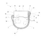
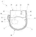
- FIG. 2 is a side view of the biological information measuring apparatus 10 shown in FIG. 1 as viewed from the elbow side (direction A in FIG. 1) of the left hand H of the person to be measured.
- the biological information measuring apparatus 10 is a metal that constitutes a main body including a pulse wave detector 22 that can detect a pulse wave (pressure pulse wave or volume pulse wave) from the radial artery TD along the rib T of the wrist W of the measurement subject.
- a housing 20 made of resin or resin and a band 40 locked to the housing 20 are provided.
- the pulse wave detector 22 can adopt a known configuration.
- the pulse wave detection unit 22 includes a pressure sensor and a mechanism that presses the pressure sensor against the skin, and detects the pressure pulse wave using the pressure sensor.
- the pulse wave detection part 22 has a photoelectric sensor, and detects a volume pulse wave from the signal detected by the photoelectric sensor.
- the case 20 is a substantially box-shaped member in the example of FIG. 1, and includes a pulse wave detection unit 22 and a heart rate, a pulse rate, or a blood pressure value based on the pulse wave detected by the pulse wave detection unit 22.
- a biological information calculation unit (not shown) that calculates the biological information.
- the biological information calculation unit may be provided in a device different from the biological information measuring device 10. That is, the housing 20 of the biological information measuring device 10 only needs to include at least the pulse wave detection unit 22. In this case, the biological information measurement device 10 functions as a pulse wave detection device.
- the surface of the housing 20 facing the wrist W (the surface facing the wrist W) constitutes a detection surface 21.
- the detection surface 21 may be substantially planar, but may be partially or entirely curved along the outer shape of the wrist W.
- the pulse wave detector 22 is provided at a position facing the radial artery TD in a state where the detection surface 21 faces the wrist W.
- a surface (opposite surface) opposite to the detection surface 21 in the housing 20 constitutes a display surface 23.
- the display surface 23 is provided with a display unit 24 composed of a liquid crystal display element or the like for displaying measurement results, and an operation unit 25 for operating the biological information measuring device 10.
- the positions where the display unit 24 and the operation unit 25 are provided are not limited to those shown in FIG. Further, the display unit 24 may be omitted.
- the first end 28 on the ulna S side (the end surface on the ulna S side of the housing 20 in the example of FIGS. 1 and 2) of the circumferential ends of the wrist W in the housing 20 is first locked.
- a portion 29 is provided.
- the first locking portion 29 is provided on the display surface 23 side at the first end portion 28. That is, the first locking portion 29 is provided in a portion of the first end portion 28 that is closer to the display surface 23 when the housing 20 is divided in half in a direction perpendicular to the display surface 23.
- the first locking portion 29 may be provided on the detection surface 21 side at the first end portion 28.
- the second end 26 on the rib T side (the end surface on the rib T side of the casing 20 in the example of FIGS. 1 and 2) of the circumferential ends of the wrist W in the casing 20 is second locked.
- a portion 27 is provided.
- the first locking portion 29 and the second locking portion 27 are for locking the band 40 to the housing 20.
- locking part 27 have a shape which has a hole part which can insert the band 40, respectively.
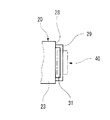
- FIG. 3 is a view of the vicinity of the first locking portion 29 of the biological information measuring apparatus 10 shown in FIG. 2 as viewed from the display surface 23 side of the housing 20.
- the first locking portion 29 is configured by a substantially letter-shaped member of Greek letters standing on the first end portion 28 of the housing 20.
- a hole 31 is formed between the first end 28.
- a band 40 can be inserted into the hole 31.
- the second locking portion 27 has the same configuration as the first locking portion 29.
- locking part 29 should just be provided in the 1st edge part 28, and is provided on the display surface 23 of the 1st edge part 28, the detection surface 21 of the 1st edge part 28, etc. May be.
- locking part 27 should just be provided in the 2nd edge part 26, and is provided on the display surface 23 of the 2nd edge part 26, the detection surface 21 of the 2nd edge part 26, etc. May be.
- the band 40 is routed so as to go around the wrist W while one end is locked to the housing 20 (it is routed so that the wrist W is sandwiched between the band 40 and the housing 20).
- the state in which the pulse wave detection unit 22 faces the radial artery TD is maintained.
- the band 40 is, for example, a band-like elongated member having a rigidity lower than that of the housing 20.
- a material of the band 40 for example, cloth, leather, rubber, or thin resin can be used. For this reason, the band 40 can be easily folded back.
- the base end portion 41 constituting one end in the longitudinal direction of the band 40 is detachably locked to a first locking portion 29 provided at the first end portion 28.
- the base end portion 41 of the band 40 is inserted into the hole portion 31 of the first locking portion 29 from the detection surface 21 side toward the display surface 23 side.
- the base end portion 41 that has passed through the hole portion 31 is folded back in a substantially U shape in a direction away from the housing 20.
- Planar fasteners 42 are respectively formed on the surface of the base end portion 41 that faces away from the housing 20 side and the surface of the base end portion 41 that faces the housing 20 side. .
- the folded portion of the base end portion 41 is detachably locked to the band 40 by the planar fastener 42.
- the planar fastener 42 is a locking member for removably locking the base end portion 41 to the band 40.
- the casing 20 of the folded portion of the base end portion 41 is formed in a concave portion or a convex portion provided on the surface facing the opposite side of the casing 20 of the non-folded portion of the base end portion 41.
- the base end 41 may be configured to be detachably locked to the band 40 by fitting a convex portion or a concave portion provided on the side facing the side.
- the concave portion and the convex portion constitute a locking member.
- the non-folded portion and the folded portion of the base end portion 41 may be completely fixed by an adhesive or sewing. That is, the base end portion 41 may be locked to the first locking portion 29 so as not to be detached.
- the band 40 locked to the first locking portion 29 has the tip portion 43 inserted into the hole of the second locking portion 27 from the detection surface 21 side toward the display surface 23 side.
- the band 40 inserted into the hole of the second locking portion 27 is folded back in a substantially U shape in a direction away from the housing 20 at an arbitrary position 44.
- the folded front end portion 43 of the band 40 is overlapped with the first end portion 28 in the circumferential direction of the wrist W by the planar fasteners 45 formed on the base end portion 41 and the front end portion 43 of the band 40, respectively. Locked to the base end 41.
- the planar fastener 45 is a locking member for removably locking the distal end portion 43 to the proximal end portion 41.
- the person to be measured inserts the base end 41 of the band 40 into the hole 31 of the first locking portion 29 of the housing 20 from the detection surface 21 side toward the display surface 23 side. Then, the person to be measured turns back the base end portion 41 that has passed through the hole portion 31 in a direction away from the housing 20, and locks the base end portion 41 to the band 40 via the planar fastener 42. Thereby, the base end portion 41 is locked to the first locking portion 29.
- the measurement subject inserts the distal end portion 43 of the band 40 into the hole portion of the second locking portion 27 of the housing 20 from the detection surface 21 side toward the display surface 23 side.
- the band 40 that has passed through the hole is folded back in a direction away from the housing 20.
- the arbitrary position 44 of the band 40 is locked to the second locking portion 27.
- the measurement subject puts his arm through the space between the detection surface 21 and the portion between the base end portion 41 of the band 40 and the arbitrary position 44.
- the person to be measured positions the housing 20 so that the pulse wave detection unit 22 faces the radial artery TD, and then turns the distal end portion 43 of the band 40 along the wrist W so that the palm from the back side of the hand.
- the front end portion 43 is pulled up to the vicinity of the first end portion 28 from the detection surface 21 side toward the display surface 23 side.
- the person to be measured adjusts the pulling force of the tip 43 of the band 40 to bring the casing 20 into close contact with the wrist W with an appropriate pressure.
- the measurement subject overlaps the distal end portion 43 of the band 40 with the proximal end portion 41 locked to the first locking portion 29 and engages with the proximal end portion 41 via the planar fastener 45. Stop.
- the distal end portion 43 of the band 40 is locked in a state where the distal end is directed from the detection surface 21 side of the housing 20 to the display surface 23 side.
- the distal end portion 43 of the band 40 is such that the position of the distal end portion 43 in the direction in which the detection surface 21 and the display surface 23 of the housing 20 are aligned (the vertical direction in FIG. 2) is the position of the housing 20 in this direction. It is locked to the base end portion 41 while being on the display surface 23 side with respect to the position of the detection surface 21.
- the distal end portion 43 of the band 40 is locked in a state where the distal end is directed from the detection surface 21 side of the housing 20 to the display surface 23 side. For this reason, the force applied to the wrist W when the band 40 is pulled can easily be applied to the thumb side and the little finger side, and the displacement of the pulse wave detector 22 can be prevented from being induced. .
- the biological information measuring device 10 can be mounted while the back of the hand is facing the desk on the desk, the displacement of the pulse wave detection unit 22 due to the movement of lifting the hand from the desk can be prevented.
- the casing 20 is fixed to the wrist W in a state where the band 40 is wound around the wrist W in a double manner as shown in FIG. As described above, since the wrist W can be covered with the double band 40, it is possible to prevent the displacement of the housing 20 after the biological information measuring apparatus 10 is mounted.
- the band 40 can be tightened in a state where the wrist 20 is positioned by inserting the wrist W into the space between the housing 20 and the band 40. For this reason, compared with the case where the band 40 is wound in a single layer, the biological information measuring device 10 can be easily attached. Moreover, the positioning accuracy of the pulse wave detector 22 can be improved.
- the friction coefficient of the surface of the band 40 on the side opposite to the side in contact with the wrist W is smaller than the friction coefficient of the surface on the side in contact with the wrist W.
- the band 40 folded back by the second locking portion 27 when the band 40 folded back by the second locking portion 27 is wound around the wrist W, the band 40 easily slips between the band 40 already wound around the wrist W. For this reason, it becomes easy to adjust the tightening degree of the band 40, and the mounting property and the positioning accuracy of the pulse wave detector 22 can be improved. Further, since the band 40 and the wrist W are less likely to slip each other on the surface in contact with the wrist W, it is possible to prevent the displacement of the housing 20 after the biological information measuring device 10 is mounted.
- the biological information measuring device 10 has a configuration in which a first locking portion 29 is provided on the display surface 23 side of the first end portion 28. According to this configuration, for example, when the wrist W is turned to the little finger side from the state where the back of the hand is directed to the table, the first locking portion 29 is unlikely to contact the table. Thereby, it is possible to obtain a good feeling of use and to prevent the positional deviation of the pulse wave detector 22.
- the biological information measuring apparatus 10 is configured such that the base end portion 41 of the band 40 is detachably locked to the first locking portion 29. According to this configuration, the band 40 can be completely removed from the housing 20. Therefore, when the band 40 is contaminated by human sweat or the external environment (dust, scratches, etc.), this can be dealt with by replacing the band 40.
- the band 40 can be exchanged.
- a plurality of types of bands 40 can be selectively used according to the person to be measured. It becomes possible. As a result, good wearability can be realized regardless of the individual.
- the biological information measuring device 10 is configured to be locked in a state in which the base end portion 41 of the band 40 is folded back in a direction away from the housing 20 at the first locking portion 29. According to this configuration, it is easy to remove the band 40 from the housing 20, and usability can be improved.
- the biological information measuring device 10 is configured such that the distal end portion 43 of the band 40 is locked to the proximal end portion 41 on the ulna S side of the wrist W.
- the measurement subject performs the work of drawing the band 40 with the right hand. For this reason, mounting
- the biological information measuring apparatus 10 has a configuration in which the distal end portion 43 of the band 40 is locked to the proximal end portion 41 by the planar fastener 45. According to this configuration, the function of the planar fastener 45 makes it easy to adjust the wrapping force of the band 40, so that the wearability can be improved.
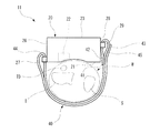
- FIG. 4 is a side view of the biological information measuring device 11 which is a modification of the biological information measuring device 10 shown in FIG. 1 as viewed from the elbow side of the left hand of the measurement subject.
- parts that are the same as those of the biological information measuring apparatus 10 are denoted by the same reference numerals, and redundant description is omitted.
- the biological information measuring device 11 has the reverse direction of the base end portion 41 of the band 40 opposite to that of the biological information measuring device 10. Further, the front end portion 43 of the band 40 is locked on the surface of the non-folded portion of the base end portion 41 facing the side opposite to the housing 20 side. Other configurations are the same as those of the biological information measuring apparatus 10.
- the base end portion 41 of the band 40 of the biological information measuring device 11 is inserted into the hole 31 of the first locking portion 29 provided on the first end portion 28 of the housing 20 from the display surface 23 side. It is inserted toward the detection surface 21 side. Then, the folded portion of the base end portion 41 is locked to the non-folded portion of the base end portion 41 by the planar fastener 42.
- distal end portion 43 of the band 40 of the biological information measuring device 11 is locked to the proximal end portion 41 by the planar fastener 45 at a position overlapping the first end portion 28 in the circumferential direction of the wrist W.
- the portion of the base end portion 41 where the front end portion 43 of the band 40 is locked becomes close to a flat surface. For this reason, the front-end
- the biological information measuring device 11 is configured to be locked in a state in which the base end portion 41 of the band 40 is folded back in a direction approaching the housing 20 at the first locking portion 29. For this reason, when the locked state with respect to the base end part 41 of the front-end
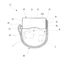
- FIG. 5 is a side view of a biological information measuring device 12 which is a modification of the biological information measuring device 10 shown in FIG. 1 as viewed from the elbow side of the left hand of the measurement subject.
- parts that are the same as those of the biological information measuring apparatus 10 are given the same reference numerals, and redundant descriptions are omitted.
- the biological information measuring device 12 is not provided with the first locking portion 29 described above at the first end portion 28 of the housing 20. Instead, the base end portion 41 of the band 40 of the biological information measuring device 12 is locked to the first end portion 28 via the planar fastener 42A.
- the planar fastener 42 ⁇ / b> A formed at the first end portion 28 constitutes a first locking portion.
- the planar fastener 42A is a locking member for removably locking the base end portion 41 to the first end portion 28.
- the concavo-convex structure described above may be employed instead of the planar fastener 42A.
- the distal end portion 43 of the band 40 of the biological information measuring device 12 is disposed on the surface facing the side opposite to the housing 20 side of the base end portion 41 locked to the first end portion 28 via the planar fastener 45. It is detachably locked.
- the portion of the base end portion 41 where the front end portion 43 of the band 40 is locked becomes close to a flat surface. For this reason, the front-end
- the base end portion 41 may be detachably locked to the first end portion 28 by adhesion or a screw. According to this configuration, the locked state of the base end portion 41 can be stably maintained.
- FIG. 6 is a side view of the biological information measuring device 13 which is a modified example of the biological information measuring device 10 shown in FIG. 1 as viewed from the elbow side of the left hand of the measurement subject.
- parts that are the same as those of the biological information measuring device 12 are assigned the same reference numerals, and redundant descriptions are omitted.
- the biological information measuring device 13 is the same as the biological information measuring device 12 shown in FIG. 5 except that the distal end portion 43 of the band 40 is locked to the first end portion 28 of the housing 20 by the planar fastener 45A. It is the same composition as.
- the distal end portion 43 of the band 40 of the biological information measuring device 13 is locked to the first end portion 28 by the planar fastener 45 ⁇ / b> A in a state of overlapping with the proximal end portion 41 in the circumferential direction of the wrist W.
- the planar fastener 45A is a locking member for removably locking the tip portion 43 to the first end portion 28.
- the concavo-convex structure described above may be employed instead of the planar fastener 45A.
- the same effect as the biological information measuring device 12 can be obtained.
- the biological information measuring device 13 when the locked state of the distal end portion 43 with respect to the housing 20 is released, the locked state between the base end portion 41 and the housing 20 is easily prevented from being released. be able to.
- the planar fastener 45 ⁇ / b> A is extended to the display surface 23, and the front end portion 43 of the band 40 is locked to the housing 20 on the two surfaces of the housing 20 and the display surface 23. It is good. According to this configuration, it is possible to prevent the vicinity of the distal end of the distal end portion 43 from being free and improve the aesthetics of the device. Moreover, peeling of the front-end
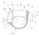
- FIG. 7 is a view showing a modification of the main body of the biological information measuring device 10.
- the same components as those in FIG. 7 are identical to those in FIG. 7;
- the body part 100 of the biological information measuring apparatus 10 shown in FIG. 7 includes a connecting part 20C such as a hinge that rotatably connects the casing 20, the casing 20B, and the casing 20 to the casing 20B. And is composed of.
- the housing 20 ⁇ / b> B houses, for example, a battery for driving the biological information measuring device 10.
- the main body 100 has a longitudinal shape along the circumferential direction of the wrist as a whole, and has a shape in which at least the ulna S side of the wrist is open.
- the main body 100 is configured so that the wrist does not cover the wrist in the circumferential direction so that a part of the band 40 comes into contact with the wrist while being attached to the wrist by the band 40.
- the end on the opposite side of the case 20 from the circumferential end of the wrist of the case 20 ⁇ / b> B constitutes the second end 26 described above, and this second end 26.
- a second locking portion 27 is formed on the top.
- the disclosed pulse wave detection device is a pulse wave detection device used by being worn on the wrist of the measurement subject, and a main body including a detection unit capable of detecting a pulse wave from the radial artery of the measurement subject, A band for maintaining the state in which the detection unit faces the radial artery by being routed so as to go around the wrist while being locked to the main body, and the wrist in the main body A first locking portion which is provided at a first end portion of the wrist on the ulna side of the wrist in the circumferential direction, and the base end portion in the longitudinal direction of the band is locked; An arbitrary position in the longitudinal direction of the band which is provided at the second end portion on the rib side of the wrist among the end portions in the direction and is locked to the first locking portion is folded back in a direction away from the main body portion.
- a second locking portion locked in a closed state, and the base locked to the first locking portion A lock for locking the distal end portion to the base end portion or the first end portion in a state where the portion and the distal end portion in the longitudinal direction of the band locked by the second locking portion overlap each other
- the distal end portion of the main body portion facing the wrist from the opposite surface side to the opposite surface side of the opposite surface, the proximal end portion or the base end portion via the locking member The first end is locked.
- the first locking portion is a hook-shaped member that is locked in a state in which the base end portion is folded back, and the opposite surface of the first end portion. It is provided on the side.
- the base end portion of the band is folded and stacked at the first locking portion, and the stacked state can be released.
- the base end portion of the band is locked in a state of being folded back in a direction away from the first end portion.
- the detection unit detects a pressure pulse wave from the radial artery using a pressure detection element.
- the disclosed biological information measuring device includes the pulse wave detection device and a biological information calculation unit that calculates biological information based on the pulse wave detected by the detection unit.
- the pulse wave detection device of the present invention is effective when applied to a portable blood pressure monitor or the like.
Landscapes
- Health & Medical Sciences (AREA)
- Life Sciences & Earth Sciences (AREA)
- Cardiology (AREA)
- Surgery (AREA)
- General Health & Medical Sciences (AREA)
- Engineering & Computer Science (AREA)
- Biomedical Technology (AREA)
- Heart & Thoracic Surgery (AREA)
- Medical Informatics (AREA)
- Molecular Biology (AREA)
- Physics & Mathematics (AREA)
- Animal Behavior & Ethology (AREA)
- Pathology (AREA)
- Public Health (AREA)
- Veterinary Medicine (AREA)
- Biophysics (AREA)
- Physiology (AREA)
- Vascular Medicine (AREA)
- Ophthalmology & Optometry (AREA)
- Measuring Pulse, Heart Rate, Blood Pressure Or Blood Flow (AREA)
Priority Applications (3)
| Application Number | Priority Date | Filing Date | Title |
|---|---|---|---|
| EP17782237.6A EP3443893B1 (en) | 2016-04-13 | 2017-03-28 | Pulse wave detection device and biological information measuring device |
| CN201780023344.6A CN109069015B (zh) | 2016-04-13 | 2017-03-28 | 脉搏波检测装置和生物信息测量装置 |
| US16/158,495 US11395598B2 (en) | 2016-04-13 | 2018-10-12 | Pulse wave detection device and biological information measuring device |
Applications Claiming Priority (2)
| Application Number | Priority Date | Filing Date | Title |
|---|---|---|---|
| JP2016080321A JP6682970B2 (ja) | 2016-04-13 | 2016-04-13 | 脈波検出装置及び生体情報測定装置 |
| JP2016-080321 | 2016-04-13 |
Related Child Applications (1)
| Application Number | Title | Priority Date | Filing Date |
|---|---|---|---|
| US16/158,495 Continuation US11395598B2 (en) | 2016-04-13 | 2018-10-12 | Pulse wave detection device and biological information measuring device |
Publications (1)
| Publication Number | Publication Date |
|---|---|
| WO2017179419A1 true WO2017179419A1 (ja) | 2017-10-19 |
Family
ID=60042452
Family Applications (1)
| Application Number | Title | Priority Date | Filing Date |
|---|---|---|---|
| PCT/JP2017/012701 Ceased WO2017179419A1 (ja) | 2016-04-13 | 2017-03-28 | 脈波検出装置及び生体情報測定装置 |
Country Status (5)
| Country | Link |
|---|---|
| US (1) | US11395598B2 (enExample) |
| EP (1) | EP3443893B1 (enExample) |
| JP (1) | JP6682970B2 (enExample) |
| CN (1) | CN109069015B (enExample) |
| WO (1) | WO2017179419A1 (enExample) |
Families Citing this family (2)
| Publication number | Priority date | Publication date | Assignee | Title |
|---|---|---|---|---|
| JP6718000B1 (ja) * | 2019-06-27 | 2020-07-08 | シチズン時計株式会社 | 血圧計 |
| CN113712515B (zh) * | 2021-09-03 | 2023-10-27 | 杭州甘芝草中医诊所有限公司 | 一种计算机程序控制的中医脉象检测装置 |
Citations (3)
| Publication number | Priority date | Publication date | Assignee | Title |
|---|---|---|---|---|
| JP2004129979A (ja) * | 2002-10-15 | 2004-04-30 | Nippon Colin Co Ltd | 血管内皮機能検査装置 |
| JP2005324004A (ja) * | 2004-04-16 | 2005-11-24 | Denso Corp | 生体状態測定装置 |
| JP2014018357A (ja) * | 2012-07-17 | 2014-02-03 | Omron Healthcare Co Ltd | 生体情報測定装置 |
Family Cites Families (7)
| Publication number | Priority date | Publication date | Assignee | Title |
|---|---|---|---|---|
| US5179956A (en) * | 1990-07-06 | 1993-01-19 | Colin Electronics Co., Ltd. | Contact pressure sensor |
| US5240007A (en) | 1991-05-14 | 1993-08-31 | Ivac Corporation | Apparatus and method for moving a tissue stress sensor for applanating an artery |
| US5830149A (en) | 1995-03-27 | 1998-11-03 | Colin Corporation | Physical information monitor system having means for indicating amount of deviation of monitored information from normal information |
| JP3599819B2 (ja) | 1995-03-27 | 2004-12-08 | コーリンメディカルテクノロジー株式会社 | 生体情報監視装置 |
| US6921006B2 (en) * | 2000-12-12 | 2005-07-26 | Tonya Daree Bauer | Quick-change watchbands |
| JP2002224098A (ja) | 2001-02-06 | 2002-08-13 | Shimadzu Corp | 医用断層撮影装置 |
| FR2836026B1 (fr) * | 2002-02-15 | 2004-05-28 | Montre Hermes Sa | Fermeture a laniere pour montre, bijou, sac ou analogue |
-
2016
- 2016-04-13 JP JP2016080321A patent/JP6682970B2/ja active Active
-
2017
- 2017-03-28 EP EP17782237.6A patent/EP3443893B1/en active Active
- 2017-03-28 CN CN201780023344.6A patent/CN109069015B/zh active Active
- 2017-03-28 WO PCT/JP2017/012701 patent/WO2017179419A1/ja not_active Ceased
-
2018
- 2018-10-12 US US16/158,495 patent/US11395598B2/en active Active
Patent Citations (3)
| Publication number | Priority date | Publication date | Assignee | Title |
|---|---|---|---|---|
| JP2004129979A (ja) * | 2002-10-15 | 2004-04-30 | Nippon Colin Co Ltd | 血管内皮機能検査装置 |
| JP2005324004A (ja) * | 2004-04-16 | 2005-11-24 | Denso Corp | 生体状態測定装置 |
| JP2014018357A (ja) * | 2012-07-17 | 2014-02-03 | Omron Healthcare Co Ltd | 生体情報測定装置 |
Non-Patent Citations (1)
| Title |
|---|
| See also references of EP3443893A4 * |
Also Published As
| Publication number | Publication date |
|---|---|
| JP6682970B2 (ja) | 2020-04-15 |
| EP3443893A4 (en) | 2019-12-11 |
| US11395598B2 (en) | 2022-07-26 |
| EP3443893A1 (en) | 2019-02-20 |
| JP2017189371A (ja) | 2017-10-19 |
| EP3443893B1 (en) | 2024-08-28 |
| CN109069015A (zh) | 2018-12-21 |
| US20190038139A1 (en) | 2019-02-07 |
| CN109069015B (zh) | 2021-07-20 |
Similar Documents
| Publication | Publication Date | Title |
|---|---|---|
| JP6662167B2 (ja) | 脈波検出装置、生体情報測定装置、脈波検出装置の装着補助部材 | |
| EP2374407B1 (en) | Optical sensor including disposable and reusable elements | |
| US20060184051A1 (en) | Apparatus and methods for non-invasively measuring hemodynamic parameters | |
| WO2008011079A2 (en) | Noninvasively measuring hemodynamic parameters | |
| WO2006124049A2 (en) | Apparatus and methods for non-invasively measuring hemodynamic parameters | |
| JP2009240511A (ja) | 生体測定装置 | |
| WO2017175618A1 (ja) | 脈波検出装置及び生体情報測定装置 | |
| WO2017179419A1 (ja) | 脈波検出装置及び生体情報測定装置 | |
| WO2017179417A1 (ja) | 脈波検出装置及び生体情報測定装置 | |
| CN107920756B (zh) | 脉搏波检测装置 | |
| WO2017043260A1 (ja) | 脈波検出装置 | |
| JP7053990B2 (ja) | センサモジュール固定器具 | |
| CN108024735B (zh) | 脉搏波检测装置 | |
| JP2526301Y2 (ja) | 指径測定具 | |
| JP2017063984A (ja) | 脈波検出装置 | |
| TWM506510U (zh) | 具黏性結構的可攜式收納裝置 |
Legal Events
| Date | Code | Title | Description |
|---|---|---|---|
| NENP | Non-entry into the national phase |
Ref country code: DE |
|
| WWE | Wipo information: entry into national phase |
Ref document number: 2017782237 Country of ref document: EP |
|
| ENP | Entry into the national phase |
Ref document number: 2017782237 Country of ref document: EP Effective date: 20181113 |
|
| 121 | Ep: the epo has been informed by wipo that ep was designated in this application |
Ref document number: 17782237 Country of ref document: EP Kind code of ref document: A1 |