EP3443893B1 - Pulse wave detection device and biological information measuring device - Google Patents
Pulse wave detection device and biological information measuring device Download PDFInfo
- Publication number
- EP3443893B1 EP3443893B1 EP17782237.6A EP17782237A EP3443893B1 EP 3443893 B1 EP3443893 B1 EP 3443893B1 EP 17782237 A EP17782237 A EP 17782237A EP 3443893 B1 EP3443893 B1 EP 3443893B1
- Authority
- EP
- European Patent Office
- Prior art keywords
- end portion
- band
- pulse wave
- wrist
- biometric information
- Prior art date
- Legal status (The legal status is an assumption and is not a legal conclusion. Google has not performed a legal analysis and makes no representation as to the accuracy of the status listed.)
- Active
Links
Images


Classifications
-
- A—HUMAN NECESSITIES
- A61—MEDICAL OR VETERINARY SCIENCE; HYGIENE
- A61B—DIAGNOSIS; SURGERY; IDENTIFICATION
- A61B5/00—Measuring for diagnostic purposes; Identification of persons
- A61B5/02—Detecting, measuring or recording for evaluating the cardiovascular system, e.g. pulse, heart rate, blood pressure or blood flow
- A61B5/024—Measuring pulse rate or heart rate
- A61B5/02438—Measuring pulse rate or heart rate with portable devices, e.g. worn by the patient
-
- A—HUMAN NECESSITIES
- A61—MEDICAL OR VETERINARY SCIENCE; HYGIENE
- A61B—DIAGNOSIS; SURGERY; IDENTIFICATION
- A61B5/00—Measuring for diagnostic purposes; Identification of persons
- A61B5/02—Detecting, measuring or recording for evaluating the cardiovascular system, e.g. pulse, heart rate, blood pressure or blood flow
- A61B5/021—Measuring pressure in heart or blood vessels
- A61B5/022—Measuring pressure in heart or blood vessels by applying pressure to close blood vessels, e.g. against the skin; Ophthalmodynamometers
-
- A—HUMAN NECESSITIES
- A61—MEDICAL OR VETERINARY SCIENCE; HYGIENE
- A61B—DIAGNOSIS; SURGERY; IDENTIFICATION
- A61B5/00—Measuring for diagnostic purposes; Identification of persons
- A61B5/02—Detecting, measuring or recording for evaluating the cardiovascular system, e.g. pulse, heart rate, blood pressure or blood flow
- A61B5/021—Measuring pressure in heart or blood vessels
- A61B5/02141—Details of apparatus construction, e.g. pump units or housings therefor, cuff pressurising systems, arrangements of fluid conduits or circuits
-
- A—HUMAN NECESSITIES
- A61—MEDICAL OR VETERINARY SCIENCE; HYGIENE
- A61B—DIAGNOSIS; SURGERY; IDENTIFICATION
- A61B5/00—Measuring for diagnostic purposes; Identification of persons
- A61B5/68—Arrangements of detecting, measuring or recording means, e.g. sensors, in relation to patient
- A61B5/6801—Arrangements of detecting, measuring or recording means, e.g. sensors, in relation to patient specially adapted to be attached to or worn on the body surface
- A61B5/6802—Sensor mounted on worn items
- A61B5/681—Wristwatch-type devices
-
- A—HUMAN NECESSITIES
- A61—MEDICAL OR VETERINARY SCIENCE; HYGIENE
- A61B—DIAGNOSIS; SURGERY; IDENTIFICATION
- A61B5/00—Measuring for diagnostic purposes; Identification of persons
- A61B5/68—Arrangements of detecting, measuring or recording means, e.g. sensors, in relation to patient
- A61B5/6801—Arrangements of detecting, measuring or recording means, e.g. sensors, in relation to patient specially adapted to be attached to or worn on the body surface
- A61B5/683—Means for maintaining contact with the body
- A61B5/6831—Straps, bands or harnesses
-
- A—HUMAN NECESSITIES
- A61—MEDICAL OR VETERINARY SCIENCE; HYGIENE
- A61B—DIAGNOSIS; SURGERY; IDENTIFICATION
- A61B2560/00—Constructional details of operational features of apparatus; Accessories for medical measuring apparatus
- A61B2560/04—Constructional details of apparatus
- A61B2560/0406—Constructional details of apparatus specially shaped apparatus housings
-
- A—HUMAN NECESSITIES
- A61—MEDICAL OR VETERINARY SCIENCE; HYGIENE
- A61B—DIAGNOSIS; SURGERY; IDENTIFICATION
- A61B5/00—Measuring for diagnostic purposes; Identification of persons
- A61B5/68—Arrangements of detecting, measuring or recording means, e.g. sensors, in relation to patient
- A61B5/6801—Arrangements of detecting, measuring or recording means, e.g. sensors, in relation to patient specially adapted to be attached to or worn on the body surface
- A61B5/6813—Specially adapted to be attached to a specific body part
- A61B5/6824—Arm or wrist
Definitions
- the present invention relates to a pulse wave detector and a biometric information measurement device.
- a biometric information measurement device is known that, in a state where a pressure sensor is directly contacted with a living body portion through which an artery such as the radial artery in the wrist passes, can measure biometric information such as the pulse rate or the blood pressure by using a pressure pulse wave detected by the pressure sensor (for example, see Patent Literatures 1 to 3).
- a blood pressure measurement device disclosed in Patent Literature 1 calculates a blood pressure value by using a cuff in a portion different from a living body portion with which a pressure sensor is contacted, and produces calibration data from the calculated blood pressure value. Then, the blood pressure measurement device calibrates a pressure pulse wave detected by a pressure pulse wave sensor which is attached to the wrist, with the calibration data, thereby calculating the blood pressure value for every pulse.
- the pressure pulse wave sensor has a configuration where the sensor is accommodated in a housing, and the housing is secured to the wrist with a band.
- Each of pressure pulse wave sensors disclosed in Patent Literatures 2 and 3 has a housing which accommodates a pressure detecting element, and a band in which a basal end portion is engaged with the housing.
- the pressure pulse wave sensor is attached to the wrist of a measurement subject by causing the band to be wound around the wrist in a state where the housing is placed so that the pressure detecting element is opposed to an artery in the wrist, and a tip end portion of the band to be engaged with the housing.
- Patent Literature 4 describes a pulse wave detector including a housing and a band for attaching the housing to a wrist, wherein the band is attached to engagement portions provided at opposite side ends of the housing.
- Patent Literature 5 discloses a pulse wave detector comprising a housing and a band, wherein a band insertion portion having an attachment hole is provided at a left side end portion the housing. An end edge portion of a second band portion of the band can be inserted into said attachment hole. Further, a band attachment portion is provided at a right side end portion of the housing, wherein the band attachment portion has an attachment portion to which a left side end portion of the second band portion is attached.
- Pulse wave detectors each of which is attached to the wrist, and detects a pulse wave from an artery in the wrist, such as those exemplified in Patent Literatures 1 to 3 are required to have superior attachability to the wrist, and accuracy of positional alignment between a pulse wave detecting section and the artery.
- the band is once folded back in a ring disposed in a portion of the housing on the side of the ulna, from the palm of the measurement subject toward the back of the hand, and a tip end portion of the folded back band is pulled toward the back of the hand. Then, the sensor is attached to the wrist by coupling the pulled tip end portion to a hook and loop fastener disposed on the band.
- the measurement subject needs to be accustomed to attachment.
- the pressure detecting element is placed on the side of the thumb of the measurement subject.
- the tip end portion of the band which is folded back in the ring that is disposed on the side of the little finger of the measurement subject is pulled toward the palm. Therefore, there is a possibility that a force which is applied to the wrist when the band is pulled acts more strongly on the side of the little finger than on the thumb side, and positional displacement of the pressure detecting element that is placed on the side of the thumb may be caused.
- the sensor is attached to the wrist by pulling a tip end portion of the band engaged with the housing from the back of the hand of the measurement subject toward the palm, and causing the tip end portion to engaging with the housing. Therefore, the above-discussed problems with respect to Patent Literature 2 can be solved.
- the band structure disclosed in Patent Literature 3 the band is singly wound around the wrist of the measurement subject. Therefore, the attachment stability is low, and there is a possibility that, after attachment, positional displacement of the pulse wave detecting section may occur.
- Patent Literature 1 fails to specifically describe the manner of winding the band around the wrist to secure the pressure pulse wave sensor to the wrist. Although, here, the problems of the devices for detecting a pressure pulse wave from the radial artery have been described, similar problems occur also in a device or the like which detects a pulse wave from the radial artery by using, for example, a photoelectric sensor.
- the present invention has been made in view of the above circumstances. It is an object of the present invention to provide a pulse wave detector which can accurately detect a pulse wave while realizing superior attachability and preventing positional displacement of a pulse wave detecting section with respect to the radial artery from occurring, and also a biometric information measurement device including the detector.
- the present invention provides a pulse wave detector in accordance with claim 1.
- the pulse wave detector according to the present invention is used while being attached to a wrist of a measurement subject and includes: a body portion which includes a detecting section disposed in a position which is opposed to a radial artery of the measurement subject and configured to detect a pulse wave from the radial artery; a band which is configured to be wound around the wrist in a state where the band is engaged with the body portion, so as to maintain a state where the detecting section is opposed to the radial artery; a first engaging portion which is disposed on a first end portion that is one of end portions of the body portion on a side of an ulna of the wrist in a circumferential direction of the wrist and on a side of an opposite surface of the body portion which is opposite to a detection surface of the body portion which is opposed to the wrist, and with which a basal end portion in a longitudinal direction of the band is engaged; a second engaging portion which is disposed on a second end portion
- the first engaging portion is configured by a first member which is erected from the first end portion of the body portion and which has a ⁇ -shape, and a first hole portion is formed between the first member and the first end portion of the body portion.
- the second engaging portion is configured by a second member which is erected from the second end portion of the body portion and which has a ⁇ -shape, and a second hole portion is formed between the second member and the second end portion of the body portion.
- the engagement members are formed on surfaces of the basal end portion and the tip end portion of the band.
- a biometric information measurement device includes the above pulse wave detector; and a biometric information calculating section which is configured to calculate biometric information based on the pulse wave detected by the detecting section.
- a pulse wave detector which can accurately detect a pulse wave while realizing superior attachability and preventing positional displacement of a pulse wave detecting section with respect to the radial artery from occurring, and also a biometric information measurement device including the detector.
- Fig. 1 is a perspective view schematically showing the external configuration of a biometric information measurement device 10 of a first embodiment of the present invention. As shown in Fig. 1 , the biometric information measurement device 10 is used while being attached to the wrist W of the left hand H of a measurement subject.
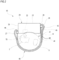
- Fig. 2 is a side view of the biometric information measurement device 10 shown in Fig. 1 , as seen from the side (the direction A in Fig. 1 ) of the elbow of the left hand H of the measurement subject.
- the biometric information measurement device 10 has: a housing 20 which constitutes a body portion including a pulse wave detecting section 22 that can detect a pulse wave (a pressure pulse wave or a volume pulse wave) from the radial artery TD extending along the radius T in the wrist W of the measurement subject, and which is formed of a metal or a resin; a band 40 which is engaged with the housing 20.
- a pulse wave a pressure pulse wave or a volume pulse wave
- the pulse wave detecting section 22 may have a known configuration.
- the pulse wave detecting section 22 has a pressure sensor, and a mechanism which presses it against the skin, and detects a pressure pulse wave by using the pressure sensor.
- the pulse wave detecting section 22 has a photoelectric sensor, and detects a volume pulse wave from a signal detected by the photoelectric sensor.
- the housing 20 is a member having an approximately box-like shape, and includes the pulse wave detecting section 22, and a biometric information calculating section (not shown) which calculates biometric information such as the heart rate, the pulse rate, or the blood pressure value based on the pulse wave detected by the pulse wave detecting section 22.
- the biometric information calculating section may be disposed in an apparatus other than the biometric information measurement device 10. Namely, the housing 20 of the biometric information measurement device 10 may need to have at least the pulse wave detecting section 22. In this case, the biometric information measurement device 10 functions as the pulse wave detector.
- the surface (the surface opposed to the wrist W) of the housing 20 which, in the case where the biometric information measurement device 10 is attached to the wrist W, is opposed to the wrist W constitutes a detection surface 21.
- the detection surface 21 may have an approximately flat shape, or a part or the whole of the surface may be arcuate so as to extend along the outer shape of the wrist W.
- the pulse wave detecting section 22 is disposed in a position which is opposed to the radial artery TD in a state where the detection surface 21 is opposed to the wrist W.
- the surface (the opposite surface) opposite to the detection surface 21 constitutes a display surface 23.
- a displaying portion 24 configured by a liquid crystal display device or the like for displaying measurement results, and an operating section 25 for operating the biometric information measurement device 10 are disposed.
- the positions where the displaying portion 24 and the operating section 25 are respectively disposed are not limited to those shown in Fig. 1 .
- a configuration where the displaying portion 24 is omitted may be employed.
- a first engaging portion 29 is disposed on a first end portion 28 (in the example of Figs. 1 and 2 , an end surface of the housing 20 on the side of the ulna S) which is one of end portions of the housing 20 on the side of the ulna S in the circumferential direction of the wrist W.
- the first engaging portion 29 is disposed on the first end portion 28, and on the side of the display surface 23. Namely, the first engaging portion 29 is disposed on a part which is in the first end portion 28, and which is on the side that is close to the display surface 23 in the case where the housing 20 is divided into halves in a direction perpendicular to the display surface 23.
- a second engaging portion 27 is disposed on a second end portion 26 (in the example of Figs. 1 and 2 , an end surface of the housing 20 on the side of the radius T) which is one of end portions of the housing 20 on the side of the radius T in the circumferential direction of the wrist W.
- the first engaging portion 29 and the second engaging portion 27 are used for causing the band 40 to engage with the housing 20.
- Each of the first engaging portion 29 and the second engaging portion 27 has a shape that has a hole portion into which the band 40 can be inserted.
- Fig. 3 is a view of the vicinity of the first engaging portion 29 of the biometric information measurement device 10 shown in Fig. 2 , as seen from the side of the display surface 23 of the housing 20.
- the first engaging portion 29 is configured by a member which is erected from the first end portion 28 of the housing 20, and which has a shape approximately similar to a Greek character ⁇ , and a hole portion 31 is formed between this member and the first end portion 28 of the housing 20.
- the band 40 can be inserted into the hole portion 31.
- the second engaging portion 27 is configured in a similar manner to the first engaging portion 29.
- the first engaging portion 29 is disposed on the first end portion 28, and is disposed on the display surface 23 of the first end portion 28.
- the second engaging portion 27 is disposed on the second end portion 26, and is disposed on the detection surface 21 of the second end portion 26.
- the band 40 is configured to be wound around the wrist W in a state where one end is engaged with the housing 20 (routed so as to form a state where the wrist W is sandwiched between the band 40 and the housing 20), so as to maintain the state where the pulse wave detecting section 22 is opposed to the radial artery TD.
- the band 40 is a strip-like member which is lower in rigidity than the housing 20.
- the material of the band 40 for example, cloth, leather, rubber, thin resin, or the like may be used. Therefore, the band 40 can be easily folded back.
- a basal end portion 41 which constitutes one end of the band 40 in the longitudinal direction is detachably engaged with the first engaging portion 29 which is disposed on the first end portion 28.
- the basal end portion 41 of the band 40 is inserted into the hole portion 31 of the first engaging portion 29, in a direction from the side of the detection surface 21 toward the display surface 23.
- the basal end portion 41 which has passed through the hole portion 31 is folded back in an approximately U-like shape in a direction to be separated from the housing 20.
- a hook and loop fastener 42 is formed on the surface of the non-folded back part of the basal end portion 41 and directed in the direction opposite to the housing 20, and the surface of the folded back part of the basal end portion 41 and directed to the housing 20. Because of the hook and loop fastener 42, the folded back part of the basal end portion 41 is detachably engaged with the band 40.
- the hook and loop fastener 42 is an engagement member for causing the basal end portion 41 to detachably engage with the band 40.
- a configuration may be employed where, in the state shown in Fig. 2 , a convex portion or concave portion which is disposed on the surface of the folded back part of the basal end portion 41 and directed to the housing 20 is fitted into a concave portion or convex portion which is disposed on the surface of the non-folded back part of the basal end portion 41 and directed in the direction opposite to the housing 20, whereby the basal end portion 41 is detachably engaged with the band 40.
- the concave portion and the convex portion constitute the engagement member.
- the non-folded back part and folded back part of the basal end portion 41 may be completely secured to each other by an adhesive agent, sewing, or the like. Namely, the basal end portion 41 may be non-detachably engaged with the first engaging portion 29.
- the tip end portion 43 is inserted into the hole portion of the second engaging portion 27 from the side of the detection surface 21 toward the display surface 23.
- the band 40 which is inserted into the hole portion of the second engaging portion 27 is folded back in the arbitrary position 44 in an approximately U-like shape in a direction to be separated from the housing 20.
- the tip end portion 43 of the folded back band 40 overlaps with the first end portion 28 in the circumferential direction of the wrist W, the tip end portion 43 is engaged with the basal end portion 41 with a hook and loop fastener 45 which is formed on the surfaces of the basal end portion 41 and tip end portion 43 of the band 40.
- the hook and loop fastener 45 is an engagement member for causing the tip end portion 43 to detachably engage with the basal end portion 41.
- a configuration may be employed where, in the state shown in Fig. 2 , a convex portion or concave portion which is disposed on the surface of the tip end portion 43 and directed to the housing 20 is fitted into a concave portion or convex portion which is disposed on the surface of the basal end portion 41 and directed in the direction opposite to the housing 20, whereby the tip end portion 43 is detachably engaged with the basal end portion 41.
- the concave portion and the convex portion constitute the engagement member.
- the measurement subject makes the basal end portion 41 of the band 40 pass through the hole portion 31 of the first engaging portion 29 of the housing 20 from the side of the detection surface 21 toward the display surface 23. Then, the measurement subject makes the basal end portion 41 which has passed through the hole portion 31, to be folded back in the direction to be separated from the housing 20 to be engaged with the band 40 through the hook and loop fastener 42. As a result, the basal end portion 41 is engaged with the first engaging portion 29.
- the measurement subject makes the tip end portion 43 of the band 40 pass through the hole portion of the second engaging portion 27 of the housing 20 from the side of the detection surface 21 toward the display surface 23, and folds back the band 40 which has passed through the hole portion of the second engaging portion 27, in the direction to be separated from the housing 20.
- the arbitrary position 44 of the band 40 is engaged with the second engaging portion 27.
- the measurement subject makes the arm pass through a space interposed between a portion between the basal end portion 41 and arbitrary position 44 of the band 40, and the detection surface 21.
- the measurement subject After the measurement subject positions the housing 20 so that the pulse wave detecting section 22 is opposed to the radial artery TD, then, the measurement subject wounds the tip end portion 43 of the band 40 around the wrist W, and pulls up the tip end portion 43 to the vicinity of the first end portion 28 while directing from the hand back side to the palm side, i.e., from the side of the detection surface 21 toward the display surface 23.
- the measurement subject adjusts the force of pulling the tip end portion 43 of the band 40, so as to cause the housing 20 to be in close contact with the wrist W at an adequate pressure.
- the measurement subject makes the tip end portion 43 of the band 40 overlap with the basal end portion 41 engaged with the first engaging portion 29 to be engaged with the basal end portion 41 through the hook and loop fastener 42.
- the tip end portion 43 of the band 40 is engaged in a state where the tip end is directed from the detection surface 21 of the housing 20 toward the display surface 23.
- the tip end portion 43 of the band 40 is engaged with the basal end portion 41 in a state where the position of the tip end of the tip end portion 43 in a direction in which the detection surface 21 and display surface 23 of the housing 20 are juxtaposed (the vertical direction in Fig. 2 ) is on the side of the display surface 23 with respect to the position of the detection surface 21 of the housing 20 in this direction.
- the tip end portion 43 of the band 40 is engaged in the state where the tip end is directed from the side of the detection surface 21 of the housing 20 toward the display surface 23. Therefore, a force which is applied to the wrist W when the band 40 is pulled is facilitated to evenly act on the side of the thumb and on the side of the little finger, and it is possible to prevent positional displacement of the pulse wave detecting section 22 from being caused.
- the attachment of the biometric information measurement device 10 can be performed while the back of the hand on a table remains to be opposed to the table surface. Therefore, it is possible to prevent positional displacement of the pulse wave detecting section 22 due to a motion of raising the hand from the table, from occurring.
- the housing 20 is secured to the wrist W in the state where the band 40 is doubly wound around the wrist W.
- the wrist W can be covered by the double portions of the band 40, and therefore it is possible to prevent positional displacement of the housing 20 from occurring after attachment of the biometric information measurement device 10.
- the band 40 can be fastened in the state where the wrist W is inserted into the space interposed between the housing 20 and the band 40, and the housing 20 is positioned. As compared with the case where the band 40 is singly wound, therefore, the biometric information measurement device 10 can be easily attached. Moreover, the accuracy of positioning the pulse wave detecting section 22 can be improved.
- a configuration may be employed where the friction coefficient of the surface of the band 40 opposite to the side which is in contact with the wrist W is smaller than that of the surface on the side which is in contact with the wrist W.
- the band 40 which is folded back in the second engaging portion 27 when the band 40 which is folded back in the second engaging portion 27 is to be wound around the wrist W, the band 40 easily slips over a portion of the band 40 which has been already wound around the wrist W. Therefore, the fastening manner of the band 40 can be easily adjusted, and the attachability and the accuracy of positioning the pulse wave detecting section 22 can be improved. With respect to the surface which is in contact with the wrist W, moreover, the band 40 and the wrist W hardly slip over each other, and therefore it is possible to prevent positional displacement of the housing 20 from occurring after attachment of the biometric information measurement device 10.
- the biometric information measurement device 10 has the configuration where the first engaging portion 29 is disposed on the first end portion 28 and on the side of the display surface 23. According to the configuration, when the wrist W on a table is turned from a state where, for example, the back of the hand is directed to the table surface, toward the side of the little finger, the first engaging portion 29 is hardly contacted with the table surface. Therefore, a superior usability is obtained, and positional displacement of the pulse wave detecting section 22 can be prevented from occurring.
- the biometric information measurement device 10 has the configuration where the basal end portion 41 of the band 40 is detachably engaged with the first engaging portion 29. According to the configuration, the band 40 can be completely detached from the housing 20. In the case where the band 40 is contaminated with human sweat or external environment (dust, scratch, or the like), therefore, this situation can be dealt with by replacement of the band 40.
- the diameter and shape of the wrist of the measurement subject are different among individuals.
- the band 40 is replaceable, a configuration may be possible where, for example, a plurality of kinds of bands 40 are selectively used in accordance with the measurement subject. As a result, regardless of individual variations, it is possible to realize superior attachability.
- the biometric information measurement device 10 has the configuration where the basal end portion 41 of the band 40 is engaged with the first engaging portion 29 in the state where the basal end portion is folded back to be separated from the housing 20. According to the configuration, a work of detaching the band 40 from the housing 20 is easily performed, and the usability can be improved.
- the biometric information measurement device 10 has the configuration where the tip end portion 43 of the band 40 is engaged with the basal end portion 41 on the side of the ulna S in the wrist W.
- the measurement subject performs a work of routing the band 40 with using the right hand. Therefore, the engagement of the tip end portion 43 of the band 40 can be performed on the side of the ulna S where the right hand exists, whereby attachment of the biometric information measurement device 10 can be easily performed.
- the biometric information measurement device 10 has the configuration where the tip end portion 43 of the band 40 is engaged with the basal end portion 41 with the hook and loop fastener 45. According to the configuration, the function of the hook and loop fastener 45 facilitates adjustment of the winding force of the band 40. Therefore, the attachability can be improved.
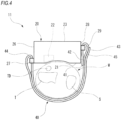
- Fig. 4 is a side view of a biometric information measurement device 11 which is a modification of the biometric information measurement device 10 shown in Fig. 1 , as seen from the side of the elbow of the left hand of the measurement subject.
- portions which are in common with the biometric information measurement device 10 are denoted by the same reference numerals, and duplicated description is omitted.
- the folding-back direction of the basal end portion 41 of the band 40 is opposite to that in the biometric information measurement device 10.
- the tip end portion 43 of the band 40 is engaged on the surface which is in the non-folded back part of the basal end portion 41, and which is directed in the direction opposite to the housing 20.
- the other configuration is identical with that of the biometric information measurement device 10.
- the basal end portion 41 of the band 40 of the biometric information measurement device 11 passes through the hole portion 31 of the first engaging portion 29 which is disposed on the first end portion 28 of the housing 20, from the side of the display surface 23 toward the detection surface 21. Then, the folded back part of the basal end portion 41 is engaged with the non-folded back part of the basal end portion 41 with the hook and loop fastener 42.
- the tip end portion 43 of the band 40 of the biometric information measurement device 11 is engaged with the basal end portion 41 with the hook and loop fastener 45, at a position where the portion overlaps with the first end portion 28 in the circumferential direction of the wrist W.
- the part of the basal end portion 41 with which the tip end portion 43 of the band 40 is engaged has an approximately flat surface. Therefore, a work of attaching or detaching the tip end portion 43 can be easily performed.
- the biometric information measurement device 11 has the configuration where the basal end portion 41 of the band 40 is engaged with the first engaging portion 29 in a state where the basal end portion is folded back in a direction approaching the housing 20.
- the engagement state of the tip end portion 43 with respect to the basal end portion 41 is to be released, therefore, the engagement state between the parts of the basal end portion 41 is hardly released. Consequently, the engagement state of the basal end portion 41 with respect to the first engaging portion 29 can be stably maintained.
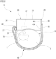
- Fig. 5 is a side view of a biometric information measurement device 12 which is a modification of the biometric information measurement device 10 shown in Fig. 1 , as seen from the side of the elbow of the left hand of the measurement subject.
- portions which are in common with the biometric information measurement device 10 are denoted by the same reference numerals, and duplicated description is omitted.
- the above-described first engaging portion 29 is not disposed on the first end portion 28 of the housing 20. Instead, the basal end portion 41 of the band 40 of the biometric information measurement device 12 is engaged with the first end portion 28 through a hook and loop fastener 42A.
- the hook and loop fastener 42A which is formed on the first end portion 28 constitutes the first engaging portion.
- the hook and loop fastener 42A is an engagement member for detachably engaging the basal end portion 41 to the first end portion 28.
- the above-described concavo-convex structure may be employed.
- the tip end portion 43 of the band 40 of the biometric information measurement device 12 is detachably engaged through the hook and loop fastener 45 with the surface of the basal end portion 41 which is engaged with the first end portion 28, the surface being directed in the direction opposite to the housing 20.
- the other configuration is similar to that of the biometric information measurement device 10.
- the part of the basal end portion 41 with which the tip end portion 43 of the band 40 is engaged has an approximately flat surface. Therefore, a work of attaching or detaching the tip end portion 43 can be easily performed.
- the basal end portion 41 may be non-detachably engaged with the first end portion 28 by adhesion, screws, or the like. According to the configuration, the engagement state of the basal end portion 41 can be stably maintained.
- Fig. 6 is a side view of a biometric information measurement device 13 which is a modification of the biometric information measurement device 10 shown in Fig. 1 , as seen from the side of the elbow of the left hand of the measurement subject.
- portions which are in common with those of the biometric information measurement device 12 are denoted by the same reference numerals, and duplicated description is omitted.
- the biometric information measurement device 13 is configured in the same manner as the biometric information measurement device 12 shown in Fig. 5 except that the tip end portion 43 of the band 40 is engaged with the first end portion 28 of the housing 20 with a hook and loop fastener 45A.
- the tip end portion 43 of the band 40 of the biometric information measurement device 13 is engaged with the first end portion 28 with the hook and loop fastener 45A in a state where the tip end portion overlaps with the basal end portion 41 in the circumferential direction of the wrist W.
- the hook and loop fastener 45A is an engagement member for causing the tip end portion 43 to detachably engage with the first end portion 28.
- the above-described concavo-convex structure may be employed.
- the biometric information measurement device 13 can attain effects similar to those of the biometric information measurement device 12. According to the biometric information measurement device 13, when the engagement state of the tip end portion 43 with respect to the housing 20 is to be cancelled, it is possible to easily prevent the engagement state between the basal end portion 41 and the housing 20 from being cancelled.
- the biometric information measurement device 13 may be configured so that the hook and loop fastener 45A is extended onto the display surface 23, and the tip end portion 43 of the band 40 is engaged with the housing 20 by two surfaces or the end surface of the housing 20 and the display surface 23. According to the configuration, it is possible to prevent the vicinity of the tip end of the tip end portion 43 from being in a free state, and the beauty of the device can be improved. Moreover, it is possible to prevent the tip end portion 43 of the band 40 from peeling off after attachment of the biometric information measurement device 10.
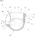
- Fig. 7 is a view showing a modification of the body portion of the biometric information measurement device 10.
- configurations which are identical with those of Fig. 2 are denoted by the same reference numerals.
- the body portion 100 of the biometric information measurement device 10 shown in Fig. 7 is configured by: the above-described housing 20; a housing 20B; and a coupling portion 20C which swingably couples together the housing 20 and the housing 20B, such as a hinge.
- the housing 20B accommodates batteries or the like for driving the biometric information measurement device 10.
- the body portion 100 has a longitudinal shape which extends along the circumferential direction of the wrist, as a whole, and a shape which is opened at least on the side of the ulna S in the wrist.
- the body portion 100 has a configuration where, in a state where the body portion is attached to the wrist with the band 40, the portion between the end portions in the circumferential direction of the wrist does not cover the wrist at a degree that a part of the band 40 is in contact with the wrist.
- an end portion which is one of the end portions of the housing 20B on the side opposite to the housing 20 in the circumferential direction of the wrist constitutes the above-described second end portion 26, and the second engaging portion 27 is formed on the second end portion 26.
- the pulse wave detector of the present invention is effective particularly in application to a portable blood pressure monitor or the like.
Landscapes
- Health & Medical Sciences (AREA)
- Life Sciences & Earth Sciences (AREA)
- Cardiology (AREA)
- Heart & Thoracic Surgery (AREA)
- Molecular Biology (AREA)
- Veterinary Medicine (AREA)
- Biophysics (AREA)
- Pathology (AREA)
- Engineering & Computer Science (AREA)
- Biomedical Technology (AREA)
- Public Health (AREA)
- Medical Informatics (AREA)
- Physics & Mathematics (AREA)
- Surgery (AREA)
- Animal Behavior & Ethology (AREA)
- General Health & Medical Sciences (AREA)
- Physiology (AREA)
- Vascular Medicine (AREA)
- Ophthalmology & Optometry (AREA)
- Measuring Pulse, Heart Rate, Blood Pressure Or Blood Flow (AREA)
Applications Claiming Priority (2)
| Application Number | Priority Date | Filing Date | Title |
|---|---|---|---|
| JP2016080321A JP6682970B2 (ja) | 2016-04-13 | 2016-04-13 | 脈波検出装置及び生体情報測定装置 |
| PCT/JP2017/012701 WO2017179419A1 (ja) | 2016-04-13 | 2017-03-28 | 脈波検出装置及び生体情報測定装置 |
Publications (3)
| Publication Number | Publication Date |
|---|---|
| EP3443893A1 EP3443893A1 (en) | 2019-02-20 |
| EP3443893A4 EP3443893A4 (en) | 2019-12-11 |
| EP3443893B1 true EP3443893B1 (en) | 2024-08-28 |
Family
ID=60042452
Family Applications (1)
| Application Number | Title | Priority Date | Filing Date |
|---|---|---|---|
| EP17782237.6A Active EP3443893B1 (en) | 2016-04-13 | 2017-03-28 | Pulse wave detection device and biological information measuring device |
Country Status (5)
| Country | Link |
|---|---|
| US (1) | US11395598B2 (enExample) |
| EP (1) | EP3443893B1 (enExample) |
| JP (1) | JP6682970B2 (enExample) |
| CN (1) | CN109069015B (enExample) |
| WO (1) | WO2017179419A1 (enExample) |
Families Citing this family (2)
| Publication number | Priority date | Publication date | Assignee | Title |
|---|---|---|---|---|
| JP6718000B1 (ja) * | 2019-06-27 | 2020-07-08 | シチズン時計株式会社 | 血圧計 |
| CN113712515B (zh) * | 2021-09-03 | 2023-10-27 | 杭州甘芝草中医诊所有限公司 | 一种计算机程序控制的中医脉象检测装置 |
Family Cites Families (10)
| Publication number | Priority date | Publication date | Assignee | Title |
|---|---|---|---|---|
| US5179956A (en) * | 1990-07-06 | 1993-01-19 | Colin Electronics Co., Ltd. | Contact pressure sensor |
| US5240007A (en) | 1991-05-14 | 1993-08-31 | Ivac Corporation | Apparatus and method for moving a tissue stress sensor for applanating an artery |
| US5830149A (en) | 1995-03-27 | 1998-11-03 | Colin Corporation | Physical information monitor system having means for indicating amount of deviation of monitored information from normal information |
| JP3599819B2 (ja) | 1995-03-27 | 2004-12-08 | コーリンメディカルテクノロジー株式会社 | 生体情報監視装置 |
| US6921006B2 (en) * | 2000-12-12 | 2005-07-26 | Tonya Daree Bauer | Quick-change watchbands |
| JP2002224098A (ja) | 2001-02-06 | 2002-08-13 | Shimadzu Corp | 医用断層撮影装置 |
| FR2836026B1 (fr) * | 2002-02-15 | 2004-05-28 | Montre Hermes Sa | Fermeture a laniere pour montre, bijou, sac ou analogue |
| JP4187498B2 (ja) * | 2002-10-15 | 2008-11-26 | オムロンヘルスケア株式会社 | 血管内皮機能検査装置 |
| JP2005324004A (ja) * | 2004-04-16 | 2005-11-24 | Denso Corp | 生体状態測定装置 |
| JP2014018357A (ja) * | 2012-07-17 | 2014-02-03 | Omron Healthcare Co Ltd | 生体情報測定装置 |
-
2016
- 2016-04-13 JP JP2016080321A patent/JP6682970B2/ja active Active
-
2017
- 2017-03-28 WO PCT/JP2017/012701 patent/WO2017179419A1/ja not_active Ceased
- 2017-03-28 EP EP17782237.6A patent/EP3443893B1/en active Active
- 2017-03-28 CN CN201780023344.6A patent/CN109069015B/zh active Active
-
2018
- 2018-10-12 US US16/158,495 patent/US11395598B2/en active Active
Also Published As
| Publication number | Publication date |
|---|---|
| CN109069015A (zh) | 2018-12-21 |
| US11395598B2 (en) | 2022-07-26 |
| US20190038139A1 (en) | 2019-02-07 |
| JP2017189371A (ja) | 2017-10-19 |
| EP3443893A1 (en) | 2019-02-20 |
| CN109069015B (zh) | 2021-07-20 |
| EP3443893A4 (en) | 2019-12-11 |
| WO2017179419A1 (ja) | 2017-10-19 |
| JP6682970B2 (ja) | 2020-04-15 |
Similar Documents
| Publication | Publication Date | Title |
|---|---|---|
| US11918327B2 (en) | Sphygmomanometer, blood pressure measurement method, and device | |
| US20100168531A1 (en) | Rapidly deployable sensor design for enhanced noninvasive vital sign monitoring | |
| EP3443894A1 (en) | Pulse wave detection device, biological information measuring device, wearing auxiliary member of pulse wave detection device | |
| EP3427646B1 (en) | Pulse wave detection device and biometric information measurement device | |
| JP2008510516A (ja) | 血行動態パラメータの非侵入的測定 | |
| US11147512B2 (en) | Pulse wave detection device and biometric information measurement device | |
| JP2009240511A (ja) | 生体測定装置 | |
| EP3443893B1 (en) | Pulse wave detection device and biological information measuring device | |
| EP3443892B1 (en) | Pulse wave detection device and biological information measuring device | |
| JP3176530U (ja) | 血圧計 | |
| US20240041337A1 (en) | Blood pressure measurement device | |
| EP3332700A1 (en) | Pulse wave detector | |
| CN107920756B (zh) | 脉搏波检测装置 | |
| US11553847B2 (en) | Pulse wave detecting device | |
| IT202000022774A1 (it) | Una fascetta di sicurezza applicabile sulle chiusure di orologi e braccialetti in genere ed integrante un sistema di rilevazione di posizione e/o del battito cardiaco | |
| JP2019201986A (ja) | 血圧測定装置 | |
| KR20230103117A (ko) | 공기 진동 전달형 다중 배열 압력 센서 및 이를 포함하는 웨어러블 장치 | |
| JP2017063984A (ja) | 脈波検出装置 |
Legal Events
| Date | Code | Title | Description |
|---|---|---|---|
| STAA | Information on the status of an ep patent application or granted ep patent |
Free format text: STATUS: THE INTERNATIONAL PUBLICATION HAS BEEN MADE |
|
| PUAI | Public reference made under article 153(3) epc to a published international application that has entered the european phase |
Free format text: ORIGINAL CODE: 0009012 |
|
| STAA | Information on the status of an ep patent application or granted ep patent |
Free format text: STATUS: REQUEST FOR EXAMINATION WAS MADE |
|
| 17P | Request for examination filed |
Effective date: 20181012 |
|
| AK | Designated contracting states |
Kind code of ref document: A1 Designated state(s): AL AT BE BG CH CY CZ DE DK EE ES FI FR GB GR HR HU IE IS IT LI LT LU LV MC MK MT NL NO PL PT RO RS SE SI SK SM TR |
|
| AX | Request for extension of the european patent |
Extension state: BA ME |
|
| DAV | Request for validation of the european patent (deleted) | ||
| DAX | Request for extension of the european patent (deleted) | ||
| A4 | Supplementary search report drawn up and despatched |
Effective date: 20191113 |
|
| RIC1 | Information provided on ipc code assigned before grant |
Ipc: A61B 5/024 20060101ALI20191107BHEP Ipc: A61B 5/02 20060101AFI20191107BHEP Ipc: A61B 5/00 20060101ALI20191107BHEP |
|
| STAA | Information on the status of an ep patent application or granted ep patent |
Free format text: STATUS: EXAMINATION IS IN PROGRESS |
|
| 17Q | First examination report despatched |
Effective date: 20210315 |
|
| GRAP | Despatch of communication of intention to grant a patent |
Free format text: ORIGINAL CODE: EPIDOSNIGR1 |
|
| STAA | Information on the status of an ep patent application or granted ep patent |
Free format text: STATUS: GRANT OF PATENT IS INTENDED |
|
| INTG | Intention to grant announced |
Effective date: 20240515 |
|
| GRAS | Grant fee paid |
Free format text: ORIGINAL CODE: EPIDOSNIGR3 |
|
| GRAA | (expected) grant |
Free format text: ORIGINAL CODE: 0009210 |
|
| STAA | Information on the status of an ep patent application or granted ep patent |
Free format text: STATUS: THE PATENT HAS BEEN GRANTED |
|
| AK | Designated contracting states |
Kind code of ref document: B1 Designated state(s): AL AT BE BG CH CY CZ DE DK EE ES FI FR GB GR HR HU IE IS IT LI LT LU LV MC MK MT NL NO PL PT RO RS SE SI SK SM TR |
|
| REG | Reference to a national code |
Ref country code: GB Ref legal event code: FG4D |
|
| REG | Reference to a national code |
Ref country code: CH Ref legal event code: EP |
|
| REG | Reference to a national code |
Ref country code: DE Ref legal event code: R096 Ref document number: 602017084477 Country of ref document: DE |
|
| REG | Reference to a national code |
Ref country code: IE Ref legal event code: FG4D |
|
| REG | Reference to a national code |
Ref country code: LT Ref legal event code: MG9D |
|
| PG25 | Lapsed in a contracting state [announced via postgrant information from national office to epo] |
Ref country code: NO Free format text: LAPSE BECAUSE OF FAILURE TO SUBMIT A TRANSLATION OF THE DESCRIPTION OR TO PAY THE FEE WITHIN THE PRESCRIBED TIME-LIMIT Effective date: 20241128 |
|
| REG | Reference to a national code |
Ref country code: AT Ref legal event code: MK05 Ref document number: 1717044 Country of ref document: AT Kind code of ref document: T Effective date: 20240828 |
|
| PG25 | Lapsed in a contracting state [announced via postgrant information from national office to epo] |
Ref country code: PL Free format text: LAPSE BECAUSE OF FAILURE TO SUBMIT A TRANSLATION OF THE DESCRIPTION OR TO PAY THE FEE WITHIN THE PRESCRIBED TIME-LIMIT Effective date: 20240828 Ref country code: NL Free format text: LAPSE BECAUSE OF FAILURE TO SUBMIT A TRANSLATION OF THE DESCRIPTION OR TO PAY THE FEE WITHIN THE PRESCRIBED TIME-LIMIT Effective date: 20240828 Ref country code: PT Free format text: LAPSE BECAUSE OF FAILURE TO SUBMIT A TRANSLATION OF THE DESCRIPTION OR TO PAY THE FEE WITHIN THE PRESCRIBED TIME-LIMIT Effective date: 20241230 Ref country code: FI Free format text: LAPSE BECAUSE OF FAILURE TO SUBMIT A TRANSLATION OF THE DESCRIPTION OR TO PAY THE FEE WITHIN THE PRESCRIBED TIME-LIMIT Effective date: 20240828 Ref country code: GR Free format text: LAPSE BECAUSE OF FAILURE TO SUBMIT A TRANSLATION OF THE DESCRIPTION OR TO PAY THE FEE WITHIN THE PRESCRIBED TIME-LIMIT Effective date: 20241129 |
|
| PG25 | Lapsed in a contracting state [announced via postgrant information from national office to epo] |
Ref country code: BG Free format text: LAPSE BECAUSE OF FAILURE TO SUBMIT A TRANSLATION OF THE DESCRIPTION OR TO PAY THE FEE WITHIN THE PRESCRIBED TIME-LIMIT Effective date: 20240828 |
|
| PG25 | Lapsed in a contracting state [announced via postgrant information from national office to epo] |
Ref country code: LV Free format text: LAPSE BECAUSE OF FAILURE TO SUBMIT A TRANSLATION OF THE DESCRIPTION OR TO PAY THE FEE WITHIN THE PRESCRIBED TIME-LIMIT Effective date: 20240828 |
|
| REG | Reference to a national code |
Ref country code: NL Ref legal event code: MP Effective date: 20240828 |
|
| PG25 | Lapsed in a contracting state [announced via postgrant information from national office to epo] |
Ref country code: AT Free format text: LAPSE BECAUSE OF FAILURE TO SUBMIT A TRANSLATION OF THE DESCRIPTION OR TO PAY THE FEE WITHIN THE PRESCRIBED TIME-LIMIT Effective date: 20240828 Ref country code: IS Free format text: LAPSE BECAUSE OF FAILURE TO SUBMIT A TRANSLATION OF THE DESCRIPTION OR TO PAY THE FEE WITHIN THE PRESCRIBED TIME-LIMIT Effective date: 20241228 |
|
| PG25 | Lapsed in a contracting state [announced via postgrant information from national office to epo] |
Ref country code: HR Free format text: LAPSE BECAUSE OF FAILURE TO SUBMIT A TRANSLATION OF THE DESCRIPTION OR TO PAY THE FEE WITHIN THE PRESCRIBED TIME-LIMIT Effective date: 20240828 |
|
| PG25 | Lapsed in a contracting state [announced via postgrant information from national office to epo] |
Ref country code: RS Free format text: LAPSE BECAUSE OF FAILURE TO SUBMIT A TRANSLATION OF THE DESCRIPTION OR TO PAY THE FEE WITHIN THE PRESCRIBED TIME-LIMIT Effective date: 20241128 Ref country code: ES Free format text: LAPSE BECAUSE OF FAILURE TO SUBMIT A TRANSLATION OF THE DESCRIPTION OR TO PAY THE FEE WITHIN THE PRESCRIBED TIME-LIMIT Effective date: 20240828 |
|
| PG25 | Lapsed in a contracting state [announced via postgrant information from national office to epo] |
Ref country code: RS Free format text: LAPSE BECAUSE OF FAILURE TO SUBMIT A TRANSLATION OF THE DESCRIPTION OR TO PAY THE FEE WITHIN THE PRESCRIBED TIME-LIMIT Effective date: 20241128 Ref country code: PT Free format text: LAPSE BECAUSE OF FAILURE TO SUBMIT A TRANSLATION OF THE DESCRIPTION OR TO PAY THE FEE WITHIN THE PRESCRIBED TIME-LIMIT Effective date: 20241230 Ref country code: PL Free format text: LAPSE BECAUSE OF FAILURE TO SUBMIT A TRANSLATION OF THE DESCRIPTION OR TO PAY THE FEE WITHIN THE PRESCRIBED TIME-LIMIT Effective date: 20240828 Ref country code: NO Free format text: LAPSE BECAUSE OF FAILURE TO SUBMIT A TRANSLATION OF THE DESCRIPTION OR TO PAY THE FEE WITHIN THE PRESCRIBED TIME-LIMIT Effective date: 20241128 Ref country code: NL Free format text: LAPSE BECAUSE OF FAILURE TO SUBMIT A TRANSLATION OF THE DESCRIPTION OR TO PAY THE FEE WITHIN THE PRESCRIBED TIME-LIMIT Effective date: 20240828 Ref country code: LV Free format text: LAPSE BECAUSE OF FAILURE TO SUBMIT A TRANSLATION OF THE DESCRIPTION OR TO PAY THE FEE WITHIN THE PRESCRIBED TIME-LIMIT Effective date: 20240828 Ref country code: IS Free format text: LAPSE BECAUSE OF FAILURE TO SUBMIT A TRANSLATION OF THE DESCRIPTION OR TO PAY THE FEE WITHIN THE PRESCRIBED TIME-LIMIT Effective date: 20241228 Ref country code: HR Free format text: LAPSE BECAUSE OF FAILURE TO SUBMIT A TRANSLATION OF THE DESCRIPTION OR TO PAY THE FEE WITHIN THE PRESCRIBED TIME-LIMIT Effective date: 20240828 Ref country code: GR Free format text: LAPSE BECAUSE OF FAILURE TO SUBMIT A TRANSLATION OF THE DESCRIPTION OR TO PAY THE FEE WITHIN THE PRESCRIBED TIME-LIMIT Effective date: 20241129 Ref country code: FI Free format text: LAPSE BECAUSE OF FAILURE TO SUBMIT A TRANSLATION OF THE DESCRIPTION OR TO PAY THE FEE WITHIN THE PRESCRIBED TIME-LIMIT Effective date: 20240828 Ref country code: ES Free format text: LAPSE BECAUSE OF FAILURE TO SUBMIT A TRANSLATION OF THE DESCRIPTION OR TO PAY THE FEE WITHIN THE PRESCRIBED TIME-LIMIT Effective date: 20240828 Ref country code: BG Free format text: LAPSE BECAUSE OF FAILURE TO SUBMIT A TRANSLATION OF THE DESCRIPTION OR TO PAY THE FEE WITHIN THE PRESCRIBED TIME-LIMIT Effective date: 20240828 Ref country code: AT Free format text: LAPSE BECAUSE OF FAILURE TO SUBMIT A TRANSLATION OF THE DESCRIPTION OR TO PAY THE FEE WITHIN THE PRESCRIBED TIME-LIMIT Effective date: 20240828 |
|
| PG25 | Lapsed in a contracting state [announced via postgrant information from national office to epo] |
Ref country code: SM Free format text: LAPSE BECAUSE OF FAILURE TO SUBMIT A TRANSLATION OF THE DESCRIPTION OR TO PAY THE FEE WITHIN THE PRESCRIBED TIME-LIMIT Effective date: 20240828 Ref country code: DK Free format text: LAPSE BECAUSE OF FAILURE TO SUBMIT A TRANSLATION OF THE DESCRIPTION OR TO PAY THE FEE WITHIN THE PRESCRIBED TIME-LIMIT Effective date: 20240828 Ref country code: RO Free format text: LAPSE BECAUSE OF FAILURE TO SUBMIT A TRANSLATION OF THE DESCRIPTION OR TO PAY THE FEE WITHIN THE PRESCRIBED TIME-LIMIT Effective date: 20240828 |
|
| PG25 | Lapsed in a contracting state [announced via postgrant information from national office to epo] |
Ref country code: EE Free format text: LAPSE BECAUSE OF FAILURE TO SUBMIT A TRANSLATION OF THE DESCRIPTION OR TO PAY THE FEE WITHIN THE PRESCRIBED TIME-LIMIT Effective date: 20240828 |
|
| PG25 | Lapsed in a contracting state [announced via postgrant information from national office to epo] |
Ref country code: CZ Free format text: LAPSE BECAUSE OF FAILURE TO SUBMIT A TRANSLATION OF THE DESCRIPTION OR TO PAY THE FEE WITHIN THE PRESCRIBED TIME-LIMIT Effective date: 20240828 |
|
| PG25 | Lapsed in a contracting state [announced via postgrant information from national office to epo] |
Ref country code: SK Free format text: LAPSE BECAUSE OF FAILURE TO SUBMIT A TRANSLATION OF THE DESCRIPTION OR TO PAY THE FEE WITHIN THE PRESCRIBED TIME-LIMIT Effective date: 20240828 Ref country code: IT Free format text: LAPSE BECAUSE OF FAILURE TO SUBMIT A TRANSLATION OF THE DESCRIPTION OR TO PAY THE FEE WITHIN THE PRESCRIBED TIME-LIMIT Effective date: 20240828 |
|
| REG | Reference to a national code |
Ref country code: DE Ref legal event code: R097 Ref document number: 602017084477 Country of ref document: DE |
|
| PLBE | No opposition filed within time limit |
Free format text: ORIGINAL CODE: 0009261 |
|
| STAA | Information on the status of an ep patent application or granted ep patent |
Free format text: STATUS: NO OPPOSITION FILED WITHIN TIME LIMIT |
|
| 26N | No opposition filed |
Effective date: 20250530 |
|
| PG25 | Lapsed in a contracting state [announced via postgrant information from national office to epo] |
Ref country code: SE Free format text: LAPSE BECAUSE OF FAILURE TO SUBMIT A TRANSLATION OF THE DESCRIPTION OR TO PAY THE FEE WITHIN THE PRESCRIBED TIME-LIMIT Effective date: 20240828 |
|
| PG25 | Lapsed in a contracting state [announced via postgrant information from national office to epo] |
Ref country code: MC Free format text: LAPSE BECAUSE OF FAILURE TO SUBMIT A TRANSLATION OF THE DESCRIPTION OR TO PAY THE FEE WITHIN THE PRESCRIBED TIME-LIMIT Effective date: 20240828 |
|
| REG | Reference to a national code |
Ref country code: CH Ref legal event code: H13 Free format text: ST27 STATUS EVENT CODE: U-0-0-H10-H13 (AS PROVIDED BY THE NATIONAL OFFICE) Effective date: 20251023 |
|
| PG25 | Lapsed in a contracting state [announced via postgrant information from national office to epo] |
Ref country code: LU Free format text: LAPSE BECAUSE OF NON-PAYMENT OF DUE FEES Effective date: 20250328 |
|
| GBPC | Gb: european patent ceased through non-payment of renewal fee |
Effective date: 20250328 |
|
| REG | Reference to a national code |
Ref country code: BE Ref legal event code: MM Effective date: 20250331 |
|
| PG25 | Lapsed in a contracting state [announced via postgrant information from national office to epo] |
Ref country code: GB Free format text: LAPSE BECAUSE OF NON-PAYMENT OF DUE FEES Effective date: 20250328 |
|
| PG25 | Lapsed in a contracting state [announced via postgrant information from national office to epo] |
Ref country code: FR Free format text: LAPSE BECAUSE OF NON-PAYMENT OF DUE FEES Effective date: 20250331 |
|
| PG25 | Lapsed in a contracting state [announced via postgrant information from national office to epo] |
Ref country code: BE Free format text: LAPSE BECAUSE OF NON-PAYMENT OF DUE FEES Effective date: 20250331 |
|
| PG25 | Lapsed in a contracting state [announced via postgrant information from national office to epo] |
Ref country code: CH Free format text: LAPSE BECAUSE OF NON-PAYMENT OF DUE FEES Effective date: 20250331 |
|
| PG25 | Lapsed in a contracting state [announced via postgrant information from national office to epo] |
Ref country code: IE Free format text: LAPSE BECAUSE OF NON-PAYMENT OF DUE FEES Effective date: 20250328 |
|
| PGFP | Annual fee paid to national office [announced via postgrant information from national office to epo] |
Ref country code: DE Payment date: 20260204 Year of fee payment: 10 |